

TECHNICAL & SERVICE MANUAL
SPLIT-TYPE,HEAT PUMP AIR CONDITIONERS
CONTENTS
1. SAFETY PRECAUTION ·····························2
2. PART NAMES AND FUNCTIONS ·············4
3. SPECIFICATIONS······································6
4. OUTLINES AND DIMENSIONS ·················8
5. WIRING DIAGRAM ····································9
6. REFRIGERANT SYSTEM DIAGRAM······10
7. TROUBLE SHOOTING ····························11
8. DISASSEMBLY PROCEDURE················16
9. PARTS LIST·············································19
<Indoor unit>
PKFY-P32VGM
PKFY-P40VGM
PKFY-P50VGM
No. OC179
1998
[ Model names ]
Wall Mounted
Series PKFY
Indoor unit
R407C/R22
[ Service Ref. ]
PKFY-P32VGM
PKFY-P40VGM
PKFY-P50VGM

2
1
SAFETY PRECAUTION
Cautions for using with the outdoor unit which adopts R407C refrigerant.
· Do not use the existing refrigerant piping.
-The old refrigerant and refrigerator oil in the existing piping contains a large amount of chlorine which may cause the
refrigerator oil of the new unit to deteriorate.
· Use “low residual oil piping”.
-If there is a large amount of residual oil (hydraulic oil, etc.) inside the piping and joints, deterioration of the refrigerator oil
will result.
· Store the piping to be used during installation indoors and keep both ends of the piping sealed until just before
brazing. (Store elbows and other joints in a plastic bag.)
-If dust, dirt, or water enters the refrigerant cycle, deterioration of the oil and compressor trouble may result.
· Use ESTR , ETHER or HAB as the refrigerator oil to coat flares and flange connection parts.
Use liquid refrigerant to seal the system.
-If gas refrigerant is used to seal the system, the composition of the refrigerant in the cylinder will change and performance
may drop.
· Do not use a refrigerant other than R407C.
-If another refrigerant (R22, etc.) is used, the chlorine in the refrigerant may cause the refrigerator oil to deteriorate.
· Use a vacuum pump with a reverse flow check valve.
-The vacuum pump oil may flow back into the refrigerant cycle and cause the refrigerator oil to deteriorate.
3
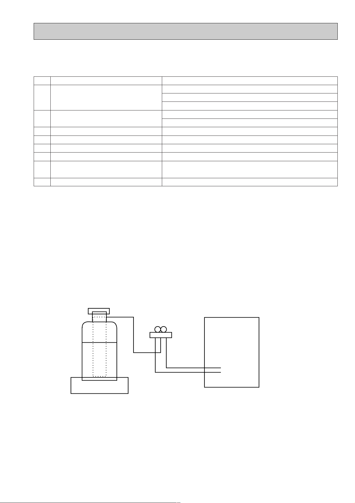
[3] Refrigerant recharging
(1) Refrigerant recharging process
1Direct charging from the cylinder.
·R407C cylinder are available on the market has a syphon pipe.
·Leave the syphon pipe cylinder standing and recharge it.
(By liquid refrigerant)
(2) Recharge in refrigerant leakage case
·After recovering the all refrigerant in the unit, proceed to working.
·Do not release the refrigerant in the air.
·After completing the repair service, recharge the cycle with the specified amount of
liquid refrigerant.
Gravimeter
Unit
[1] Service tools
Use the below service tools as exclusive tools for R407C refrigerant.
No. Tool name Specifications
1 Gauge manifold ·Only for R407C.
·Use the existing fitting SPECIFICATIONS. (UNF7/16)
·Use high-tension side pressure of 3.43MPa·G or over.
2 Charge hose ·Only for R407C.
·Use pressure performance of 5.10MPa·G or over.
3 Electronic scale
4 Gas leak detector ·Use the detector for R134a or R407C.
5 Adapter for reverse flow check. ·Attach on vacuum pump.
6 Refrigerant charge base.
7 Refrigerant cylinder. ·For R407C ·Top of cylinder (Brown)
·Cylinder with syphon
8 Refrigerant recovery equipment.
[2] Notice on repair service
·After recovering the all refrigerant in the unit, proceed to working.
·Do not release refrigerant in the air.
·After completing the repair service, recharge the cycle with the specified amount of
liquid refrigerant.
4
PART NAMES AND FUNCTIIONS
2
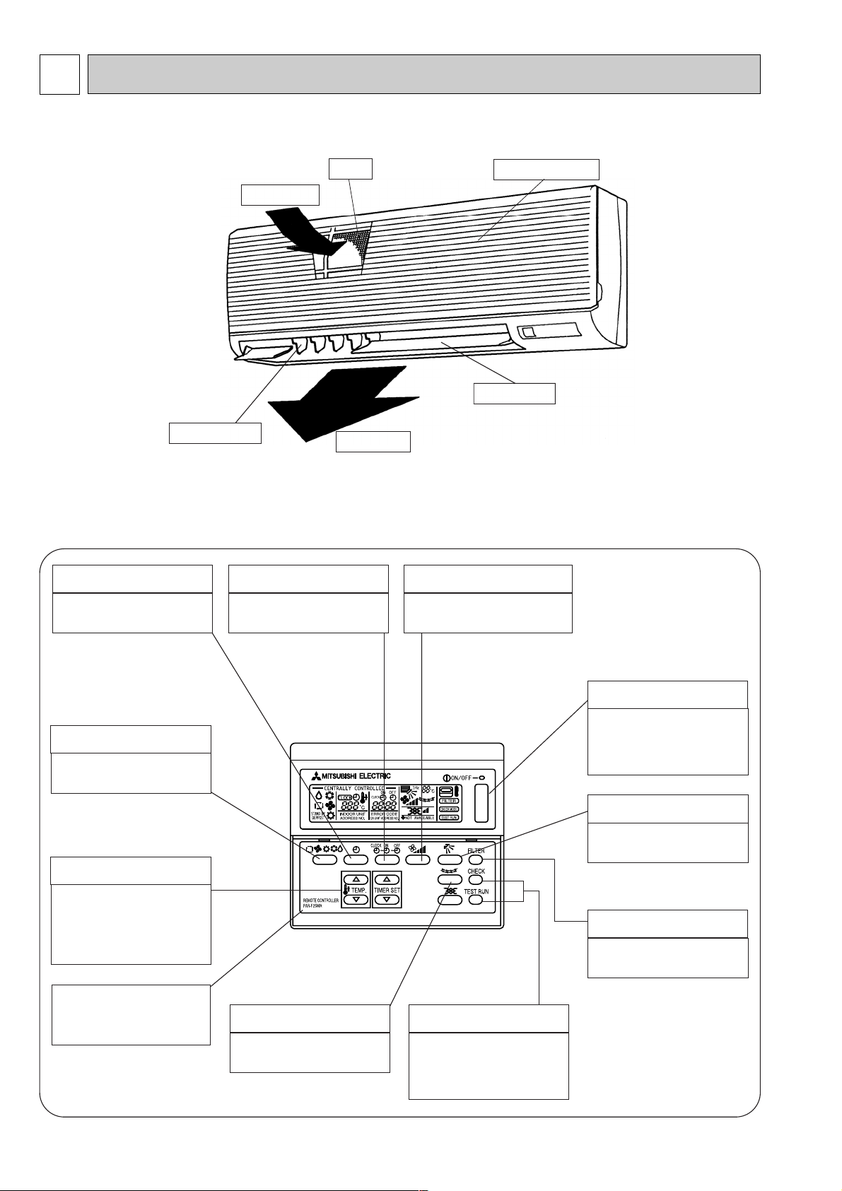
● Indoor Unit
PKFY-P32VGM
PKFY-P40VGM
PKFY-P50VGM
● Remote controller [PAR-F25MA]
● Once the controls are set, the same operation mode can be repeated by simply pressiry the on / off button.
TIMER button
This switches between continuous
operation and the timer operation
AIR SPEED button
The sets the ventilation fan speed.
● Operation buttons
TIME SETTING button
This sets or switches the current
time, start time and stop time.
OPERATION SWITCH button
Press this button to switch the cooler
electronic dry (denumidity),
automatic and heater modes.
TEMP ADJUSTMENT button
This sets the room temperature. The
temperature setting can be
performed in 1°C units.
Setting range :
Cooler 19°C to 30°C
Heater 17°C to 28°C
CHECK-TEST RUN button
Only press this button to perform an
inspection check or test operation.
Do not use it for nomal operation
FILTER button
This resets the filter service
indication display
AIR DIRECTION button
This adjusts the vertical angle of the
ventilation.
ON/OFF button
This switches between the operation
and stop modes each time it is
pressed. The lamp on this button
lights during operation.
The model name of the remote
controller is indicated.
LOUVER button
This switches the horizontal fan
motion ON and OFF.
(This button does not operate in this
model.)
Air intake
Air intake gril
Filter
Air outlet
Guide vane
Auto vane
5
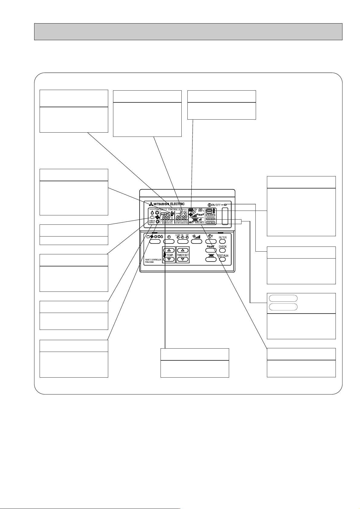
Caution
● Only the Power display lights when the unit is stopped and power supplied to the unit.
● When power is turned ON for the first time the (CENTRAL CTRL) display appears to go off momentarily but this is not a
malfunction.
● When the central control remote control unit, which is sold separately, is used the ON-OFF button, Operation switch button
and i TEMP button do not operate.
● “NOT AVAILABLE” is displayed when the Air speed button and the Louver button are pressed.This indicates that this room unit
is not equipped with the fan direction adjustment function and the louver function.
● When power is turned ON for the first time, it is normal that “ HO ” is displayed on the room temperature indication (For max.
2 minutes).Please wait until this “ HO ” indication disapear then start the operation.
CENTRALLY
CONTROLLED display
This indicates when the unit is
controlled by optional features such
as central control type remote
controller.
TIMER display
This indicates when the continuous
operation and time operation modes
are set.
It also display the time for the timer
operation at the same time as when
it is set.
OPERATION MODE display
This indicates the operation mode.
STANDBY display
This indicates when the standby
mode is set from the time the sleep
operation starts until the heating air
is discharged.
DEFROST display
This indicates when the defrost
operation is performed.
CHECK display
This indicates when a malfunction
has occurred in the unit which should
be checked.
POWER display
This display lights when the filter
need to be cleaned.
SET TEMPERATURE display
This displays the selected setting
temperature.
CLOCK display
The current time , start time and stop
time can be displayed in tensecond
intervals by pressing the time switch
button. The start time or stop time is
always displayed during the timer
operation.
FAN SPEED display
The selected fan speed is displayed.
● Display
In this display example on the
bottom left, a condition where
all display lamps light is
shown for explanation
purposes although this differs
from actual operation.
display
This display lights in the check mode
or when a test operation is
performed.
CHECK MODE
TEST RUN
ROOM TEMPERATURE display
The temperature of the suction air is
displayed during operation. The
display range is 8° to 39°C. The
display flashes 8°C when the actual
temperature is less than 8° and
flashes 39°C when the actual
temperature is greater than 39°C.
Operation lamp
This lamp lights during operation,
goes off when the unit stops and
flashes when amalfunction occurs.
6
3
SPECIFICATIONS
3-1 Specification
12 - 11 - 10 - 9
15.88 <5/8">
9.52 <3/8">
43 - 40 - 37 - 34
Power
consumption
Current
Type ✕ No.
Air flow w2
External stafic pressure
Fan motor output
Item
Power source
Cooling capacity
Heating capacity
Exterior <munsell symbol>
Dimensions
Heat exchanger
Fan
Air filter
Refrigerant
Pipe dimensions
Drain pipe dimension
Noise level w2
Product weight
Unit
V · Hz
kcal/h
kcal/h
kW
kW
A
A
—
mm
mm
mm
—
—
k/min
Pa
kW
—
[mm
[mm
[mm
dB (A)
kg
Cooling
Heating
Cooling
Heating
Height
Width
Depth
Gas side
Liquid side
PKFY-P32VGM
3150
3550
PKFY-P40VGM
4000
4500
Single phase 220-240V 50Hz
0.07
0.07
0.32
0.32
Plastic , white : <0.70Y 8.59/0.97>
340
990
235
Cross fin(Aluminum plate fin and copper tube)
Lineflow fan ✕ 1
0
0.03
PP Honey comb
Outer dimeter 20 <PVC pipe VP-20 connectable>
16
Electric
characteristic
PKFY-P50VGM
5000
5600
11.5 - 10.5 - 9.5 - 8
12.7 <1/2">
6.35 <1/4">
41 - 38 - 36 - 33
Note : w1. Rating conditions
Cooling : Indoor 27°C DB. 19.5°C WB
Outdoor 35°C DB. 24°C WB
Heating : Indoor 21°C DB.
Outdoor 7°C DB. 6°C WB
W2. Air flow and the noise level are indicated as High - Middium1 - Middium2 - Low .

7
3-2 Electrical parts specifications
Transformer
Room temperature thermistor
Liquid pipe thermistor
Gas pipe thermistor
Fuse
(Indoor controller board)
Fan motor
(with inner-thermostat)
Fan motor capacitor
Vane motor
Linear expansion valve
Power supply terminal block
Transmission terminal block
Symbol
T
TH21
TH22
TH23
FUSE
MF
C1
MV
LEV
TB2
TB5
PKFY-P32VGM
PKFY-P40VGM
(Primary) 50/60Hz 220 - 240V (Secondary) 18.4V 1.7A
Resistance
0$C/15k1, 10$C/9.6k1, 20$C/6.3k1, 25$C/5.4k1, 30$C/4.3k1, 40$C/3.0k1
250V 6.3A
PM4V30-K 220-240V/220V , 50/60Hz
4 pole Output 30W
OFF 125(5;
2.0+F 440V
MP 35 EA DC12V
DC12V Stepping motor drive
Port dimension [3.2 (0 ~ 2000pulse)
(L, N, ;) 330V 30A
(M1, M2, S) 250V 20A
Model
Parts name
PKFY-P50VGM
Inner-thermostat

8
OUTLINES AND DIMENSIONS4
Unit : mm
PKFY- P32VGM
PKFY- P40VGM
PKFY- P50VGM
Installation plate
balance point hole
49 - [5 hole
for tapping screw
Knock out hole for
right-rear piping
Right-rear
piping hole
( Necessary clearance for Unit installation )
R
5
2
.5
R52.5
R
52.5
R
52.5
Unit center
Right side
Allowing clearances
Front view
W1 Sleeves are available on the market.
W2 This size shows the lower end of through hole.
[90 ~ [100
[75 ~ [80
[90
[75
Through holeSleeve W1
50
32 , 40
Model
Details of installation plate
14 - [14 hole
for bolts
Left-rear
piping hole
Knock out hole for
left-rear piping
Less than 130
50 or more 150 or more
180 or more
30 or more
425
420
170
190
210
230
0
322
0355580130
190
230
272
310
0
35
95
150
205
260
320
345
495
20
75
135
190
245
300
360
405
495
32
0
Knock out hole for right piping
Refrigerant pipe.Drain pipe.
Wiring hole
Gas pipe
Liquid pipe
Address board
Terminal block for
power supply
Terminal block for
remote control
Filter grip
21
21
Knock out hole for under piping
Refrigerant piping.Drain pipe.
Wiring hole
Service panel
(Power supply access)
5/8F
Gas pipe
1/2F
Liquid pipe
3/8F
1/4F
50
32 , 40
Model
( Flexible hose total length 800 )
( Right side piping
installation )
( Left side piping
installation )
Drain pipe (VP-20)
(Front view ( to open the grille ))
12 - Louvers ( manual )
Air outlet
(Lower side)
Auto vane
(Left side)
(Front view)
Air intake
Air intake
Air intake
Air intake
Knock out hole for left piping
Refrigerant pipe.Drain pipe.Wiring hole.
(Right side)
35
700 153
549 86
481 54
31
280
80
60
70
245
50
395400
190
60
70 35
79
160 40
705 235
Less than 15
198
70
245
60
235
53
340
715 225
340 80 280 233
990

9
5
WIRING DIAGRAM
PKFY-P32VGM , PKFY-P40VGM , PKFY-P50VGM
ÇO
PIN
BLU
YLW
ORN
RED
BRN
SW3
109876
ON
OFF
12345
SW2
ON
OFF
123456
P32VGM
Models
ON
OFF
123456
P40VGM
109876
ON
OFF
12345
Models SW2
P50VGM
ON
OFF
123456 54321
OFF
ON
678910
SW3
< W1 >
See fig: W1
ORN
BLU
RED
BRN
WHT
YLW
(RED)
CN50
DRAIN
CN29
GAS
(BLK)
CN21
LIQUID
(WHT) (RED)
CN20
INTAKE
N
TB2
L
GRN/YLW
~ 220-240V 50Hz
POWER SUPPLY
PULL BOX
BREAKER(15A)
FUSE(15A)
TO NEXT INDOOR UNIT
BLU
BLU
S(SHIELD)
M1
M2
REMOTE CONTROLLER
DC24-30V
{
BC CONTROLLER
TO OUTDOOR UNIT
TB5
(BLU)
M-NET
CN2M
AC220-240V
T
AC18.4V
RED
BLU
BLU
BLU
CN52
(WHT)
REMOTE
INDICATION
CN51
CENTRALLY
CONTROL
(WHT)
LEV
(WHT)
CN60
CN32
REMOTO
SWITCH
(WHT)
BLU
RED
FUSE
250V
6.3A
CND
(RED)
CN3T
(RED)
ADDRESS
(RED)
CN42
ADDRESS
(RED)
CN81
(GRN)
VANE
CN6V
RED
WHT
CNT
(WHT)
FAN1
(WHT)
WHT
BLK
RED
3RD
DIGIT
2ND
DIGIT
1ST
DIGIT
CONNEC
(RED)
ADDRESS
CN82
CN43
(RED)
ADDRESS
240V220V
SW5
SWC
CN26
4
1
135151
4
32
X4
TH22
LED5
LED2
LED1
LED3LED4
0N
SW4
1
4
1
0N
1234567891023456
SW3SW2
ON
OFF
12345678910
SW1
SW12 SW11
A.B
00
F.C
HA
CN41
6
ZNR
X4
SW14
0
0FF
MV
8
0FF
LEV
TH23 TH21
(WHT)
I.B
C1
1.At servicing for outdoor unit,always follow the wiring diagram of outdoor unit.
2.Symbol[S] of TB5 is the shield wire connection.
3.Symbols used in wiring diagram above are, :terminal block, :connecter.
4.The setting of the SW2 dip switches differs in the capacity for the detail,see the table below.
5.Please set the switch SW5 according to the power supply voltare.
Set SW5 to 240V side when the power supply is 230 and 240 volts.
When the power supply is 220 volts, set SW5 to 220V side.
21
12
123456
123412345678561234
4
3
2
1
8
7
6
5
4
3
2
1
1221
12345
13
31
1
2
31
513
132
MF
Note
-TION No.
PKFY-
PKFY-
PKFY-
Mode selection
A.B
SW12
SW11
SW1
SW14
SW5
SWC Option selector
Connection No.
Address setting 2nd digit
Address setting 1st digit
Voltage selection
Switch
Address board
Transmission
Power supply
(0;/15T,25;/5.4T)
Liquid Pipe temperature
(0;/15T,25;/5.4T)
Gas Pipe temperature
(0;/15T,25;/5.4T)
Transformer
Fan motor (with inner thermostat)
Capacitor (fan motor)
Room temperature
TH22
TH23
C1
MF
T
TH21
Thermistor
TB2
TB5
LEV
block
Terminal
Linear expansion valve
MV
Vane motor
Symbol Name Symbol NameNameSymbol
F.C Fan phase control
Fuse (6.3A)FUSE
I.B
ZNR
X4
SW3
SW4
SW2
CN52
CN51
CN41
CN32
Indoor controller board
Connector
Aux.Relay (Fan motor)
Varistor
Mode selection
Capacity cord
Remote indication
Centrally control
Remote switch
HA terminal-A
Switch
Model selection

10
REFRIGERANT SYSTEM DIAGRAM6
Strainer (#50mesh)
Strainer (#100mesh)
Strainer (#100mesh)
Heat exchanger
Room temperature thermistor
TH21
Gas pipe thermistor
TH23
Liquid pipe thermistor
TH22
Linear expansion valve
Gas pipe
Flare connection
PKFY-P32VGM
PKFY-P40VGM
PKFY-P50VGM
Gas pipe
PKFY-P32VGM, PKFY-P40VGM
{12.7 <1/2F>
Liquid pipe
{6.35 <1/4F>
Capacity
Item
Refrigeration pipe size (Flare connection size)
PKFY-P50VGM
[15.88<5/8F>
[9.52<3/8F>

11
7
TROUBLE SHOOTING
7-1 How to check PKFY-P32VGM , PKFY-P40VGM , PKFY-P50VGM
Room temperature
thermistor (TH21)
Liquid pipe
thermistor (TH22)
Gas pipe thermistor
(TH23)
Trans
Vane motor
Fan motor
Linear expansion
valve
Disconnect the connector then measure the resistance with the tester.
(Surrounding temperature 10°C~30°C)
Disconnect the connector then measure the resistance with the tester
Measure the resistance between the terminals using the tester.
(Surrounding temperature 20°C~30°C)
Disconnect the connector then measure the resistance with the tester.
(Surrounding temperatuer 20°C)
Normal
4.3k'~9.6k'
Abnormal
Open or short
Normal Abnormal
186' ~ 214'
Open or short
CNT(1)-(3)
CN3T(1)-(3)
Normal Abnormal
Open or short
Motor terminal or
relay connector
Normal Abnormal
Red - Black 141.21
Open or short
White - Black 131.51
Normal
(1)-(5)
White-Red
150' ±10%
Abnormal
Open or short
(2)-(6)
Yellow-
Blown
(3)-(5)
Orange-Red
(4)-(6)
Blue-Brown
Parts name Check method
Measure the resistance between the terminals using the tester.
(Surrounding temperatuer 20°C)
M
Blue
Brown
Yellow
Orange
Red
Pink
4
5
2
3
6
1
Red - Pink
Connector
Brown - Yellow
Brown - Blue
Red - Orange
About 70'
About 1'
CNT T CN3T
Red Blue
1
2
3
White
Relay connector
1
2
3
Blue
Red
White
Black
1
2
3
1
2
3
LEV
Protector
White
Yellow
Orange
Blue
Red
Brown
CN60
1
2
3
4
5
6

12
<Thermistor Characteristic graph>
Room temperature thermistor(TH21)
Liquid pipe thermistor (TH22)
Gas pipe thermistor (TH23)
Drain sensor(THD)
Thermistor R
0=15k' ±3%
Fixed number of B=3480k' ±2%
Rt=15exp { 3480( ) }
0: 15k'
10: 9.6k'
20: 6.3k'
25: 5.2k'
30: 4.3k'
40: 3.0k'
Thermistor for
lower temperature
Linear expansion valve
① Operation summary of the linear expansion valve.
• Linear expansion valve open/close through stepping motor after receiving the pulse signal from the indoor controller board.
• Valve position can be changed in proportion to the number of pulse signal.
1
273+t
1
273
<Connection between the indoor controller board and the linear expasion valve>
< Thermistor for lower temperature >
50
40
30
Resistance (K")
20
10
0
-20 -10 0 10 20 30 40 50
Temperature (:)
Linear expansion valve
4
M
6
2
5
White
1
Red
3
Orange
Blue
Brown
Yellow
[4
[3
[2
[1
Brown
Red
Blue
Orange
Yellow
White
Connector(CN60)
Controller board
DC12V
6
5
4
3
2
1
Drive circuit
[4
[3
[2
[1

13
Output
(Phase)
Output
{1
1
ON
{2
ON
{3
OFF
{4
OFF
2
OFF
ON
ON
OFF
3
OFF
OFF
ON
ON
4
ON
OFF
OFF
ON
<Output pulse signal and the valve operation>
➁
Linear expansion valve operation
➂
Trouble shooting
D
A
E
B
C
Open
Extra tightning (80~100pulse)
Pulse number
2000 pulse
Opening a valve
all the way
Close
Valve position (capacity)
Symptom
Check points
Operation circuit
failure of the micro
processor.
Disconnect the connector on the controller board, then
connect LED for checking.
Pulse signal will be sent out for 10 seconds as soon as the
main switch is turned on. If there is LED with lights on or
lights off, it means the operation circuit is abnormal.
Countermeasures
Exchange the indoor
controller board at drive
circuit failure.
Linear expansion
valve mechanism is
locked.
Valve doesn't close
completely
(thermistor leaking).
Wrong connection of
the connector or
contact failure.
To check the linear expansion valve, operate the indoor unit
in fan mode and at the same time operate other indoor units
in cooling mode, then check the pipe temperature <liquid
pipe temperature> of the indoor unit by the
outdoor multi controller board operation
monitor. During fan operation, linear
expansion valve is closed completely and if
there are some leaking, detecting
temperature of the thermistor will go lower.
If the detected temperature is much lower
than the temperature indicated in the
remote controller, it means the valve is not closed all the way.
It is not necessary to exchange the linear expansion valve, if
the leakage is small and not making any trouble.
Liquid pipe
thermistor
Linear
expansion
valve
Motor will idle and make ticking noise when motor is operated
while the linear expansion valve is locked. This ticking sound
is the sign of the abnormality.
Check the color of lead wire and missing terminal of the
connector.
Exchange the linear
expansion vale.
Exchange the linear
expansion valve.
If large amount of
thermistor is leaked,
exchange the linear
expansion valve.
Disconnect the connector
at the controller board,
then check the continuity.
Measure the resistance between the each coil (red-white,
red-orange, brown-yellow, brown-blue) using a tester. It is
normal if the resistance is in the range of 150'+10%.
Short or breakage of
the motor coil of the
linear expansion
valve.
Closing a valve : 1 → 2 → 3 → 4 → 1
Opening a valve : 4 → 3 → 2 → 1 → 4
The output pulse shifts in above order.
❈ 1. When linear expasion valve operation stops, all output phase
become OFF.
2. At phase interruption or when phase does not shift in order,
motor does not rotate smoothly and motor locks and vibrates.
❈ When the switch is turned on, 2200 pulse closeing valve signal will
be send till it goes to
A
point in order to define the valve
position.
When the valve move smoothly, there is no noise or vibration
occurring from the linear expansion valve : however, when the
pulse number moves from
E
to Aor when the valve is locked,
more noise can be heard than normal situation.
❈ Noise can be detected by placing the ear against the screw
driver handle while putting the screw driver to the linear
expansion valve.
LED1T
6
5
4
3
2
1

14
7-2. FUNCTION OF DIPSWITCH
PKFY-P32VGM , PKFY-P40VGM , PKFY-P50VGM
1
2
3
4
5
6
7
8
9
10
1~6
1
2
3
4
5
6
7
8
9
10
1~4
Thermistor<Intake temperature
detection>position
ON OFF
Filter crogging detection Provided Not provided
Filter life 2500hr 100hr
Air intake Effective Not effective
Remote indication switching Thermostat ON signal indication Fan output indication
Humidifier control
Always operated while the heating mode w1Operated depends on the condition
w2
Air flow set in case of Fix to LOW w3 Fix to EXTRA LOW w3
Heat thermostat OFF
Depends on setting Remote controller
w3 Depends on SW1-7
Auto restart Effective Not effective
Power ON/OFF Effective Not effective
Heat pump/Cooling only Cooling only models Heat pump models
Louver Available Not available
Vane Available Not available
Vane swing function Available Not available
Vane holizontal angle Second setting First setting
Vane cooling limit angle setting
w4 Horizontal angle Down A,B,C
Effective Not effective
Heater 4deg up Not effective Effective
Target Superheat setting
w5 9degrees 6degrees
Target Subcool setting 15degrees 10degrees
ON
OFF
1234
ON
OFF
12345678910
ON
OFF
123456
MODELS SW2 MODELS SW2 MODELS SW2
PKFY-
P32VGM
PKFY-
P40VGM
Address board
<At delivery>
Indoor controller board
Indoor controller board
Indoor controller board
<At delivery>
SW4
Unit
Selection
SW3
Function
Selection
SW2
Capacity
code
setting
SW1
Mode
Selection
Switch Pole
Function
Operation by switch
Remarks
Bult-in remote controller
Indoor unit
Indoor linear expansion
valve opening
NOTE:
w1 At Heating mode, fan
operating.
w2 At Heating mode, operat-
ing heat thermostat ON.
w3 SW1-7=OFF, SW1-8=ON
→Setting air flow.
SW1-7=ON, SW1-8=ON
→Indoor fan stop.
Set while the unit is off.
<At delivery>
Set for each capacity.
Set while the unit is off.
NOTE:
w4 At cooling mode, each
angle can be used only 1
hour.
w5 sw3-9 setting
PKFY-P32VGM = OFF
PKFY-P40VGM = ON
PKFY-P50VGM = OFF
Set while the unit is off.
PKFY-
P50VGM
ON
OFF
123456
ON
OFF
123456
ON
OFF
12345678910
<At delivery>
ON
OFF
1234

15
Address board
Address board
Operation by switchSwitch Pole Remarks
<At delivery>
<At delivery>
SW11
1st digit
address
setting
SW12
2nd degit
address
setting
Rotary switch
SW14
Connect
ion No.
setting
Rotary switch
Address setting should be done when network
remote controller (PAR-F25MA) is being used.
This is the switch to be used when the indoor
unit is operated with R2, R3 series outdoor
unit as a set.
220V 240V
220V 240V
Address board
<At delivery>
2
SW/5
Voltage
Selection
If the unit is used at the 230V or 240V area,
set the voltage to 240V.
If the unit is used at the 220V, set the voltage
to 220V.
Address can be set while the
unit is stopped.
10 1
SW12
0
1
9
2
8
3
7
4
6
5
SW14
0
F
E
D
C
B
A
9
SW11
1
2
3
4
5
6
7
8
0
1
9
8
7
6
5
2
3
4
SW12
SW11
0
9
8
7
6
0
1
5
1
9
2
8
3
7
4
6
5
2
3
4
SW14
0
1
2
F
3
E
4
D
5
C
6
B
7
A
8
9

16
8
DISASSEMBLY PROCEDURE
PKFY-P40VGM
OPERATION PROCEDURE
PHOTOS & ILLUSTRATION
1 REMOVE THE LOWER SIDE OF THE INDOOR UNIT FROM
THE INSTALLATION PLATE.
(1) Remove the left / right corner box of the indoor unit.
(2) Hold and pull down the lower and both ends of the indoor
unit, and remove the ▼ section from the square hole.
(Refer to the figure 2.1)
Or remove the front panel and push the ▼ section down
by using alankey ,etc. from the front side.
(Refer to the figure 2.2).
(3) Unhook the top of the indoor unit from the back plate catch.
2 REMOVING THE FRONT PANEL.
(1) Open the front grille.
(2) Remove the terminal block cover with a screw.
(3) Remove the screw 3caps then remove the set 3screws.
(4) After removing the lower side of the front panel a little,
remove it as pulling toward upper.
3 REMOVING THE INDOOR CONTROLLER BOARD.
(1) Remove the terminal block cover.
(2) Remove the front panel. (see the photo 1)
(3) Remove the electrical parts box(2screws).
(4) Remove the electrical parts box cover(1screw).
(5) Disconnect the connector on the indoor controller board and
remove the controller board by Pulling up the hook of the
controller case.
w To smooth works, hang the side hooks of the electrical
parts box on the hook of the motor cover.
(see the photo 3)
(Figure 1)
(Figuer2.1)
(Figuer 3)
(Photo 1)
(Photo 2)
(Figuer 2.2)
Square hole
Up
Down
Hook
Square hole
Hook
Terminal block cover
Front grille
Front
panel
Set screw
Set screw
Electrical parts
box
Set screw
Motor cover
Electrical parts
box hook w
(Photo 3)
Hook
Electrical parts box
Controller case
Indoor control
p.c.board

17
OPERATION PROCEDURE
PHOTOS & ILLUSTRATION
4 REMOVING THE VANE MOTOR
(1) Disconnect the connector CN6V on the indoor controller
board.
(2) Remove the 2screws of the vane motor, disconnect the
lead wire and remove the vane motor from the shaft.
(Photo 4)
(Photo 5)
(Photo 6)
(Photo 7)
(Photo 8)
7.REMOVING THE ELECTRICAL PARTS BOX
(1) Remove the terminal block cover.
(2) Remove the front panel.(see the photo 1)
(3) Disconnect the vane motor connector.
(4) Disconnect the fan motor connector from the fan motor.
(5) Remove the liquid / gas pipe thermistor.(see the photo 5)
(6) Remove the electrical parts box (2screws).
Nozzle
assemble
Set screws
Lead wire
Van motor
5.REMOVING THE THERMISTOR
(1) Removing the room thermistor TH21.
1Disconnect the connector CN20<red> on the indoor
controller board.
2Remove the room thermistor from the holder.
(2) Removing the liquid pipe thermistor TH22.
1Disconnect the connector CN21<white> on indoor con-
troller board.
2Remove the liquid pipe thermistor with set to the pipe.
(3) Removing the gas pipe thermistor TH23.
1Disconnect the connector CN29<blak> on hte indoor con-
troller board.
2Remove the gas pipe thermistor with set to the pipe.
Electrical
parts box
Liquid
thermistor
Room
thermistor
Gas pipe
thermistor
6.REMOVEING THE NOZZLE ASSEMBLE
(1) Disconnect the connector CN6V on the indoor controller
.board.
(2) Disconnect the lead wire of the vane motor.
(3) Remove the corner cover.
(4) Pull the drain hose out from the nozzle assemble.
(5) Unhook the hook of the lower nozzle assemble and
pull the nozzle assemble toward you,then remove the
nozzle assemble by sliding it down.
Nozzle assemble
Hook
Drain hose
Corner cover
Liquid pipe
thermistor
Fan motor connector
Vane motor
connector
Electrical
parts box
8.REMOVING THE FAN MOTOR.
(1) Remove the terminal block cover.
(2) Remove the front panel.(see the photo 1)
(3) Remove the electrical parts box.(see the photo 7)
(4) Remove the nozzle assemble.(see the photo 6)
(5) Remove the fan motor leg fixing 3screws.
(6) Unscrew the set screws using by alankey and remove it by
sliding the fan motor to right.
(7) Remove the 4screws and remove the motor cover from the
fan motor leg.
(Photo 9)
screws
Set
screw
Fan motor
Motor cover
motor
leg

18
9 . REMOVING THE LINE FLOW FAN
(1) Remove the terminal block cover.
(2) Remove the front panel.(see the photo 1)
(3) Remove the electrical parts box.(see the photo 7)
(4) Remove the nozzle assembly.(see the photo 6)
(5) Remove the fan motor.(see the photo 8)
(6) Remove the pipe fixture with 2screws.(see the photo11)
(7) Remove the left / right screws of the heat exchanger and
pull the left-hand side up.
(8) Remove the 2screws by sliding it towerd you remove the
fixture(fixing bearing).
w The fan motor is removable first , when the fan
removing is hard.
w When resetting the fan to the fan motor.
Locate and fix the shaft after installing the fan.
(Photo10)
Heat exchenger
Set screws
Fixture(fixing bearing)
10 . REMOVING THE HEAT EXCHANGER
(1) Remove the terminal block cover.
(2) Remove the front panel.(see the photo 1)
(3) Remove the electrical parts box.(see the photo 7)
(4) Remove the corner box.
(5) Remove the nozzle assemble.(see the photo 6)
(6) Remove the 2screws and the pipe fixture.
(7) Remove the 2screws and heat exchanger.
(Photo 11)
Heat exchenger
Set screw
Pipe fixture
Set screws

19
PKFY-P32VGM
PKFY-P40VGM STRUCTURAL PARTS
PKFY-P50VGM
1
2
3
4
5
6
7
8
9
10
11
12
13
FRONT PANEL
AIR FILTER
SCREW CAP
CORNER COVER
CORNER COVER
BOX ASSEMBLY
BACK PLATE
UNDER COVER
FRONT GRILLE
ADDRESS BOARD
ADDRESS CABLE
VANE SLEEVE
AUTO VANE
1
2
3
1
1
1
1
1
1
1
1
1
1
No.
Parts No.
Parts Name
Specifications
PKFY-
P32/P40/P50VGM
Remarks
(Drawing No.)
Wiring
Diagram
Symbol
Recommended
Q'ty
Unit
Amount
Price
R01 89Y 651
R01 A16 500
R01 07Y 096
R01 09Y 658
R01 07Y 658
R01 07Y 635
R01 07Y 808
R01 07Y 623
R01 07Y 691
T7W B01 294
T7W 85Y 304
R01 07Y 092
R01 07Y 002
PARTS LIST
9
9
3
4
2
11
8
5
7
6
1
10
13
12

20
PKFY-P32VGM
PKFY-P40VGM ELECTRICAL PARTS
PKFY-P50VGM
FILTER
CHECK MODE
TEST RUN
241
21
29
22
T7W A01 762
R01 07Y 114
R01 07Y 105
R01 07Y 106
R01 005 103
R01 07Y 102
R01 07Y 130
R01 07Y 530
R01 89Y 202
R01 09Y 038
R01 89Y 223
R01 07Y 527
T7W E02 310
T7W 520 239
R01 07Y 524
T7W 521 716
T7W E00 716
R01 588 255
R01 KL5 202
T7W A00 260
R01 A03 480
R01 A04 480
R01 A05 480
T7W B00 713
T7W A00 305
R01 07Y 135
R01 07Y 038
R01 07Y 059
R01 18J 202
T7W A00 675
R01 22A 401
No.
Parts No. Parts Name
Specifications
Remarks
(Drawing No.)
Wiring
Diagram
Symbo
l
Recom-
mended
Q'ty
Unit
Amount
PKFY-
P40VGMP32VGM
Price
1
2
3
4
5
6
7
8
9
10
11
12
13
14
15
16
17
18
19
20
21
22
23
24
25
26
27
28
29
FAN MOTOR
LINE FLOW FAN
RUBBER MOUNT
BEARING SUPPORT
SLEEVE BEARING
BEALING MOUNT
MOTOR SUPPORT
NOZZLE ASSY
GAS PIPE THERMISTOR
GUIDE VANE
VANE MOTOR
DRAIN HOSE
CONTROLLER BOARD
FUSE
DRAIN PLAG
TERMINAL BLOCK
TERMINAL BLOCK
RUN CAPACITOR 2
LIQUID PIPE THERMISTOR
POWER TRANS
HEAT EXCHANGER
HEAT EXCHANGER
HEAT EXCHANGER
REMOCON
CORD REMOCON
MOTOR COVER
GUIDE VANE
ARM
ROOM THERMISTOR
FAN GUARD
LINEAR EXPANSION VALVE
1
1
2
1
1
1
1
1
1
4
1
1
1
1
1
1
1
1
1
1
1
1
1
1
10
2
1
1
1
1
1
2
1
1
1
1
1
1
4
1
1
1
1
1
1
1
1
1
1
1
1
1
1
10
2
1
1
1
MF
TH23
MV
I.B
F1<I.B>
TB2
TB5
C1
TH22
T
TH21
LEV
P50VGM
1
1
2
1
1
1
1
1
1
4
1
1
1
1
1
1
1
1
1
1
1
1
1
1
10
2
1
1
1
PAR-F25MA
10m
3P
25 11 12
24
1
13
2
3
6
5
4
7
8
10
14
15
17
16
18
Part numbers that are circled are not shown in the figure.
27199
20
26
28


cCopyright 1998 MITSUBISHI ELECTRIC ENGINEERING CO.,LTD.
Issued in Dec. 1998. OC179 1
Issued in Dec. 1998. OC179 357
Printed in Japan
HEAD OFFICE MISTUBISHI DENKI BLDG.MARUNOUCHI TOKYO100-8310 TELEX J24532 CABLE MELCO TOKYO
New publication, effective Dec. 1998
Specifications subject to change without notice
 Loading...