

Mitsubishi PKFY-P40VLM-E, PKFY-P15VLM-E, PKFY-P50VLM-E, PKFY-P20VLM-ET, PKFY-P15VLM-ET Operation Manual
...
Air-Conditioners For Building Application
INDOOR UNIT
Кондиционеры для установки в помещениях
ВНУТРЕННИЙ БЛОК
Bina Uygulaması için Klimalar
İÇ ÜNİTE
PKFY-P·VLM Series
OPERATION MANUAL
For safe and correct use, please read this operation manual thoroughly before operating the air-conditioner unit.
РУКОВОДСТВО ПО ЭКСПЛУАТАЦИИ
Для обеспечения правильного и безопасного использования следует ознакомиться с инструкциями,
указанными в данном руководстве по эксплуатации, тщательным образом до того, как приступать к
использованию кондиционера.
Işletme Elkitabı
Emniyetli ve doğru biçimde nasıl kullanılacağını öğrenmek için lütfen klima cihazını işletmeden önce bu elkitabını dikkatle okuyunuz.
FOR USER
ДЛЯ ПОЛЬЗОВАТЕЛЯ
KULLANICI İÇİN
English (EN)
Русский (RU)
Türkçe (TR)

Manual Download
http://www.mitsubishielectric.com/ldg/ibim/
EN Go to the above website to download manuals, select model name, then choose language.
DE Besuchen Sie die oben stehende Website, um Anleitungen herunterzuladen, wählen Sie den Modellnamen und dann die Sprache aus.
FR Rendez-vous sur le site Web ci-dessus pour télécharger les manuels, sélectionnez le nom de modèle puis choisissez la langue.
NL Ga naar de bovenstaande website om handleidingen te downloaden, de modelnaam te selecteren en vervolgens de taal te kiezen.
ES Visite el sitio web anterior para descargar manuales, seleccione el nombre del modelo y luego elija el idioma.
IT Andare sul sito web indicato sopra per scaricare i manuali, selezionare il nome del modello e scegliere la lingua.
EL Μεταβείτε στον παραπάνω ιστότοπο για να κατεβάσετε εγχειρίδια. Επιλέξτε το όνομα του μοντέλου και, στη συνέχεια, τη γλώσσα.
PT Aceda ao site Web acima indicado para descarregar manuais, seleccione o nome do modelo e, em seguida, escolha o idioma.
DA Gå til ovenstående websted for at downloade manualer og vælge modelnavn, og vælg derefter sprog.
SV Gå till ovanstående webbplats för att ladda ner anvisningar, välj modellnamn och välj sedan språk.
TR Kılavuzları indirmek için yukarıdaki web sitesine gidin, model adını ve ardından dili seçin.
RU Чтобы загрузить руководства, перейдите на указанный выше веб-сайт; выберите название модели, а затем язык.
UK Щоб завантажити керівництва, перейдіть на зазначений вище веб-сайт; виберіть назву моделі, а потім мову.
BG Посетете горепосочения уебсайт, за да изтеглите ръководства, като изберете име на модел и след това – език.
PL Odwiedź powyższą stronę internetową, aby pobrać instrukcje, wybierz nazwę modelu, a następnie język.
NO Gå til nettstedet over for å laste ned håndbøker og velg modellnavn, og velg deretter språk.
FI Mene yllä mainitulle verkkosivulle ladataksesi oppaat, valitse mallin nimi ja valitse sitten kieli.
CS Příručky naleznete ke stažení na internetové stránce zmíněné výše poté, co zvolíte model a jazyk.
SK Na webovej stránke vyššie si môžete stiahnuť návody. Vyberte názov modelu a zvoľte požadovaný jazyk.
HU A kézikönyvek letöltéséhez látogasson el a fenti weboldalra, válassza ki a modell nevét, majd válasszon nyelvet.
SL Obiščite zgornjo spletno stran za prenos priročnikov; izberite ime modela, nato izberite jezik.
RO Accesaţi site-ul web de mai sus pentru a descărca manualele, selectaţi denumirea modelului, apoi alegeţi limba.
ET Kasutusjuhendite allalaadimiseks minge ülaltoodud veebilehele, valige mudeli nimi ja seejärel keel.
LV Dodieties uz iepriekš norādīto tīmekļa vietni, lai lejupielādētu rokasgrāmatas; tad izvēlieties modeļa nosaukumu un valodu.
LT Norėdami atsisiųsti vadovus, apsilankykite pirmiau nurodytoje žiniatinklio svetainėje, pasirinkite modelio pavadinimą, tada – kalbą.
HR Kako biste preuzeli priručnike, idite na gore navedeno web-mjesto, odaberite naziv modela, a potom odaberite jezik.
SR Idite na gore navedenu veb stranicu da biste preuzeli uputstva, izaberite ime modela, a zatim izaberite jezik.
Contents
1. Safety Precautions .................................................................3
2. Parts Names ...........................................................................4
3. Operation ................................................................................9
4. Timer.....................................................................................12
To dispose of this product, consult your dealer.
Note
Fig.1
Note:
The phrase “Wired remote controller” in this operation manual refers to the PAR-40MAA.
If you need any information for the other remote controller, please refer to the instruction book included in this box.
Your MITSUBISHI ELECTRIC product is designed and manufactured with high quality materials and components which can be
recycled and/or reused. This symbol means that electrical and electronic equipment, batteries and accumulators, at their end-of-
life, should be disposed of separately from your household waste. If a chemical symbol is printed beneath the symbol (Fig. 1), this
chemical symbol means that the battery or accumulator contains a heavy metal at a certain concentration.
This will be indicated as follows: Hg: mercury (0,0005%), Cd: cadmium (0,002%), Pb: lead (0,004%)
Please, help us to conserve the environment we live in!
Compliance with the “India e-waste (Management) Rules, 2016”
This product complies with the “India e-waste (Management) Rules, 2016” and prohibits use of lead, mercury, hexavalent chromium,
polybrominated biphenyls or polybrominated diphenyl ethers in concentrations exceeding 0.1% by weight and 0.01% by weight for
cadmium, except for the exemption set in Schedule II of the Rule.
5. Emergency Operation for Wireless Remote-controller .........12
6. Care and Cleaning................................................................13
7. Troubleshooting ....................................................................15
8. Specifications .......................................................................17
1. Safety Precautions
Before installing the unit, make sure you read all the
“Safety Precautions”.
The “Safety Precautions” provide very important
points regarding safety. Make sure you follow them.
Please report to or take consent by the supply
authority before connection to the system.
Symbols used in the text
Warning:
Describes precautions that should be observed to prevent danger
of injury or death to the user.
Caution:
Describes precautions that should be observed to prevent damage
to the unit.
Warning:
• These appliances are not accessible to the general public.
• The unit must not be installed by the user. Ask the dealer or an
authorized company to install the unit. If the unit is installed
improperly, water leakage, electric shock or fire may result.
• Do not alter the unit. It may cause fire, electric shock, injury or
water leakage.
• Do not stand on, or place any items on the unit.
• Do not splash water over the unit and do not touch the unit with
wet hands. An electric shock may result.
• Do not spray combustible gas close to the unit. Fire may result.
• Do not place a gas heater or any other open-flame appliance
where it will be exposed to the air discharged from the unit.
Incomplete combustion may result.
• Do not remove the front panel or the fan guard from the outdoor
unit when it is running.
• Never repair the unit or transfer it to another site by yourself.
• When you notice exceptionally abnormal noise or vibration, stop
operation, turn off the power switch, and contact your dealer.
• Never insert fingers, sticks etc. into the air inlets or outlets.
• If you detect odd smells, stop using the unit, turn off the power
switch and consult your dealer. Otherwise, a breakdown, electric
shock or fire may result.
• This air conditioner is NOT intended for use by children or infirm
persons without supervision.
• If the refrigeration gas blows out or leaks, stop the operation of
the air conditioner, thoroughly ventilate the room, and contact
your dealer.
Caution:
• Do not use any sharp object to push the buttons, as this may
damage the remote controller.
•
Never block or cover the indoor or outdoor unit’s air inlets or outlets
• Never wipe the remote controller with benzene, thinner chemical
rags, etc.
Symbols used in the illustrations
: Indicates a part which must be grounded.
• This appliance is intended to be used by expert or trained users
in shops, in light industry and on farms, or for commercial use by
lay persons.
• Children should be supervised to ensure that they do not play
with the air conditioner.
• This appliance is not intended for use by persons (including
children) with reduced physical, sensory or mental capabilities,
or lack of experience and knowledge, unless they have been
given supervision or instruction concerning use of the appliance
by a person responsible for their safety.
• This appliance can be used by children aged from 8 years and
above and persons with reduced physical, sensory or mental
capabilities or lack of experience and knowledge if they have
been given supervision or instruction concerning use of the
appliance in a safe way and understand the hazards involved.
Children shall not play with the appliance. Cleaning and user
maintenance shall not be made by children without supervision.
• When installing or relocating, or servicing the air conditioner, use
only the specified refrigerant (R410A) to charge the refrigerant
lines. Do not mix it with any other refrigerant and do not allow air
to remain in the lines.
If air is mixed with the refrigerant, then it can be the cause of
abnormal high pressure in the refrigerant line, and may result in
an explosion and other hazards. The use of any refrigerant other
than that specified for the system will cause mechanical failure
or system malfunction or unit breakdown. In the worst case, this
could lead to a serious impediment to securing product safety.
• Do not operate the unit for a long time in high humidity, e.g.
leaving a door or window open. In the cool mode, if the unit is
operated in a room with high humidity (80% RH or more) for a
long time, water condensed in the air conditioner may drop and
.
wet or damage furniture, etc.
• Do not touch the upper air outlet vane or the lower air outlet
damper during operation. Otherwise, condensation may form and
the unit may stop operating.
EN
Disposing of the unit
When you need to dispose of the unit, consult your dealer.
3
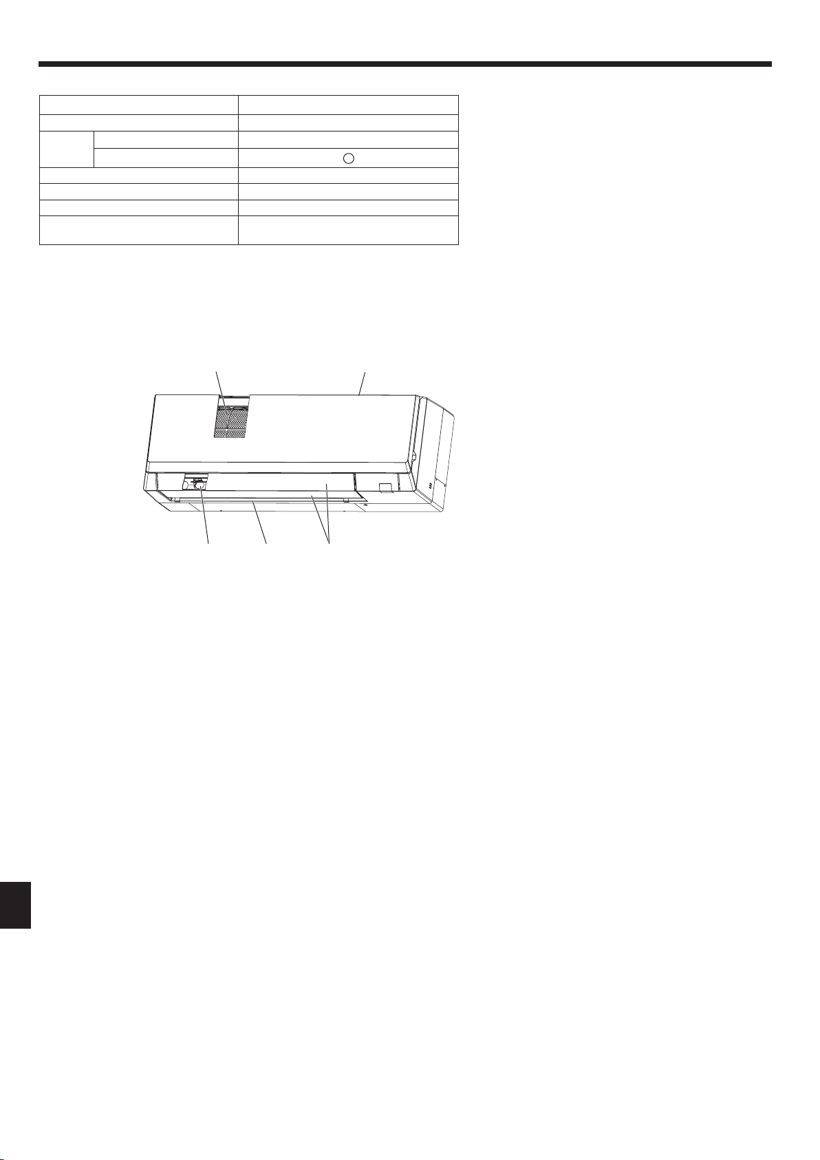
2. Parts Names
■ Indoor Unit
PKFY-P·VLM
Fan speed 4 speed + Auto
Vane
Louver Manual
Filter Normal
Filter cleaning indication 100 hr
Enter the model setting number for
the indoor unit you want to operate.*
* For systems that are capable of simultaneous cooling and heating operation, use the setting indicated in parentheses ( ).
For details on the setting procedure, refer to the Installation Manual.
■ PKFY-P·VLM
Wall Mounted
Steps 5 steps
Auto swing
065 (001)
Filter
Air intake
EN
VaneAir outletLouver
4
2. Parts Names
■
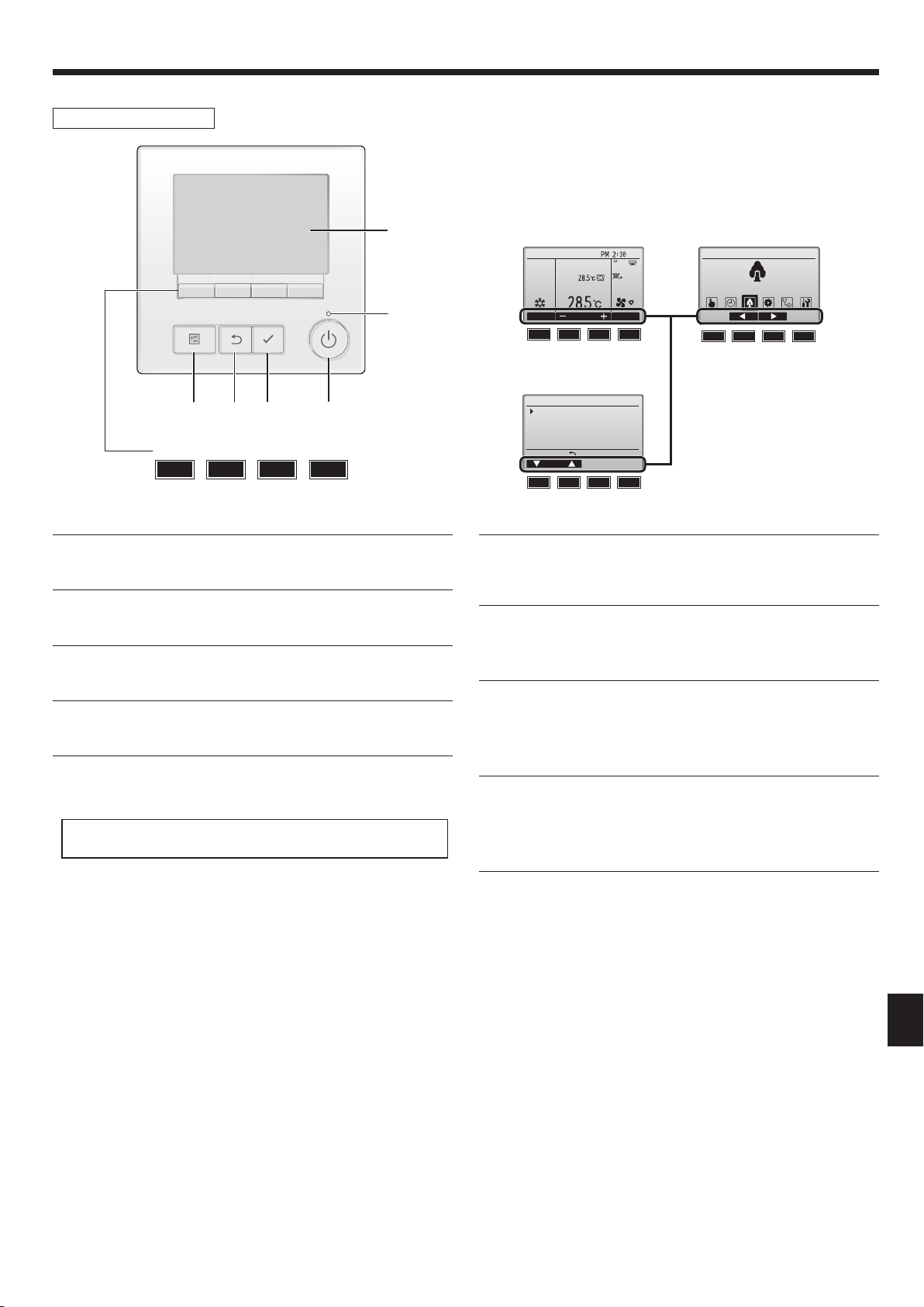
Wired Remote Controller
Controller interface
The functions of the function buttons change depending on the
screen.
Refer to the button function guide that appears at the bottom of the
LCD for the functions they serve on a given screen.
When the system is centrally controlled, the button function guide
that corresponds to the locked button will not appear.
5
Main display Main menu
Room
Set temp.
Cool Auto
Fri
Main Main menu
Energy saving
6
4 3 2
Function buttons
1
7 8 9 0
▌1 [ON/OFF] button
Press to turn ON/OFF the indoor unit.
▌2 [SELECT] button
Press to save the setting.
▌3 [RETURN] button
Press to return to the previous screen.
▌4 [MENU] button
Press to bring up the Main menu.
▌5 Backlit LCD
Operation settings will appear.
When the backlight is off, pressing any button turns the backlight on
and it will stay lit for a certain period of time depending on the screen.
When the backlight is off, pressing any button turns the backlight on
and does not perform its function. (except for the [ON/OFF] button)
Mode Temp. Fan
7 8 9 0 7 8 9 0
Menu screen
Operation
Vane·Louver·Vent. (Lossnay)
High power
Comfort
Main display:
Cursor
Function guide
7 8 9 0
▌6 ON/OFF lamp
This lamp lights up in green while the unit is in operation. It blinks while
the remote controller is starting up or when there is an error.
▌7 Function button [F1]
Main display: Press to change the operation mode.
Menu screen: The button function varies with the screen.
▌8 Function button [F2]
Main display: Press to decrease temperature.
Main menu: Press to move the cursor left.
Menu screen: The button function varies with the screen.
▌9 Function button [F3]
Main display: Press to increase temperature.
Main menu: Press to move the cursor right.
Menu screen: The button function varies with the screen.
▌0 Function button [F4]
Main display: Press to change the fan speed.
Menu screen: The button function varies with the screen.
EN
5
2. Parts Names
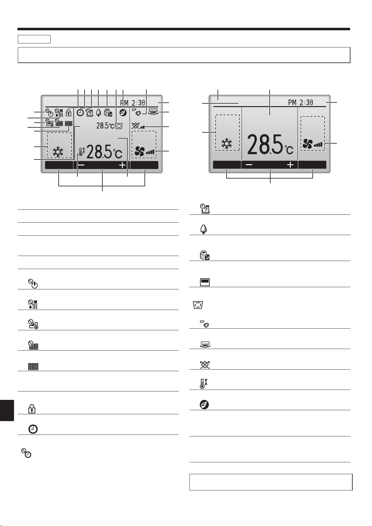
Display
The main display can be displayed in two different modes: “Full” and “Basic”. The factory setting is “Full”. To switch to the “Basic” mode, change the
setting on the Main display setting. (Refer to operation manual included with remote controller.)
<Full mode>
* All icons are displayed for explanation.
2 3 4 5 6 7 @
6
7
8
9
0
Cool
Room
Set temp. Auto
1
1
Mode Temp. Fan
!
5
▌1 Operation mode
▌2 Preset temperature
▌3 Clock
Current time appears here.
▌4 Fan speed
▌5 Button function guide
Functions of the corresponding buttons appear here.
2
8
Fri
3
9
)
4
<Basic mode>
$
#
Cool
2
Set temp.
Fri
Auto
1
Mode Temp. Fan
5
▌4
Appears when the Weekly timer is enabled.
▌5
Appears while the units are operated in the energy-save mode. (Will
not appear on some models of indoor units)
▌6
Appears while the outdoor units are operated in the silent mode.
(This indication is not available for CITY MULTI models.)
3
4
▌6
Appears when the ON/OFF operation is centrally controlled.
▌7
Appears when the operation mode is centrally controlled.
▌8
Appears when the preset temperature is centrally controlled.
▌9
Appears when the filter reset function is centrally controlled.
▌0
Indicates when filter needs maintenance.
▌1 Room temperature
Current room temperature appears here.
▌2
EN
Appears when the buttons are locked.
▌3
Appears when the On/Off timer, Night setback, or Auto-off timer
function is enabled.
appears when the timer is disabled by the centralized control
system.
▌7
Appears when the built-in thermistor on the remote controller is
activated to monitor the room temperature (1).
appears when the thermistor on the indoor unit is activated to
monitor the room temperature.
▌8
Indicates the vane setting.
▌9
Indicates the louver setting.
▌)
Indicates the ventilation setting.
▌!
Appears when the preset temperature range is restricted.
▌@
Appears when an energy-saving operation is performed using a “3D i-
See sensor” function. (not available)
▌# Centrally controlled
Appears for a certain period of time when a centrally-controlled item is
operated.
▌$ Preliminary error display
An error code appears during the preliminary error.
Most settings (except ON/OFF, mode, fan speed, temperature) can be
made from the Main menu. (Refer to Page 10.)
6
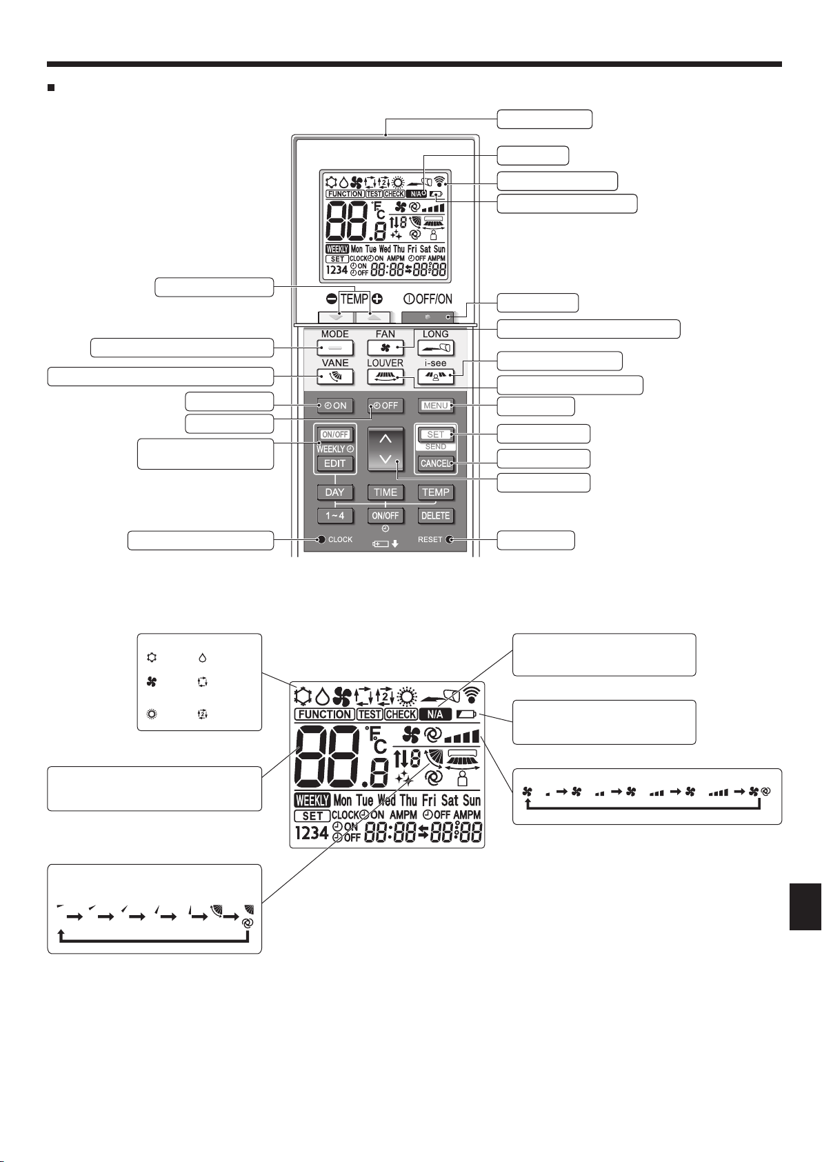
2. Parts Names
Wireless Remote-Controller (Optional parts)
Set Temperature buttons
Mode button (Changes operation mode)
Airfl ow button (Changes up/down airfl ow direction)
Timer ON button
Timer OFF button
Weekly timer ON/OFF button
(not available)
Transmission area
Not available
Remote controller display
Battery replacement indicator
OFF/ON button
Fan Speed button (Changes fan speed)
i-see button (not available)
LOUVER button (not available)
Menu button
SET/SEND button
CANCEL button
Up/Down buttons
Set Time button (Sets the time)
Operation mode
Cool Dry
Fan
Heat
* The initial setting is necessary.
Refer to Installation manual.
Temperature setting
The units of temperature can be changed. For
details, refer to the Installation manual.
Vane setting
Step 1 Step 2 Step 3 Step 4 Step 5 Swing Auto
Auto
(single set
point)
Auto*
(dual set
point)
Reset button
Not available
Appears when a non-supported function is selected.
Battery replacement indicator
Appears when the remaining battery
power is low.
Fan speed setting
EN
7
2. Parts Names
Notes (Only for wireless remote controller):
When using the wireless remote controller, point it towards the receiver on the indoor unit.
If the remote controller is operated within approximately 2 minutes after power is supplied to
the indoor unit, the indoor unit may beep twice as the unit is performing the initial automatic
check.
The indoor unit beeps to confirm that the signal transmitted from the remote controller has
been received. Signals can be received up to approximately 7 meters in a direct line from the
indoor unit in an area 45° to the left and right of the unit. However, illumination such as fluores-
cent lights and strong light can affect the ability of the indoor unit to receive signals.
If the operation lamp near the receiver on the indoor unit is blinking, the unit needs to be in-
spected. Consult your dealer for service.
Handle the remote controller carefully! Do not drop the remote controller or subject it to strong
shocks. In addition, do not get the remote controller wet or leave it in a location with high hu-
midity.
To avoid misplacing the remote controller, install the holder included with the remote controller
on a wall and be sure to always place the remote controller in the holder after use.
If the indoor unit beeps 4 times when you are using the wireless remote controller, switch the
auto mode setting to the AUTO (single set point) mode or AUTO (dual set point) mode.
For details, refer to the included Notice (A5 sheet) or the Installation Manual.
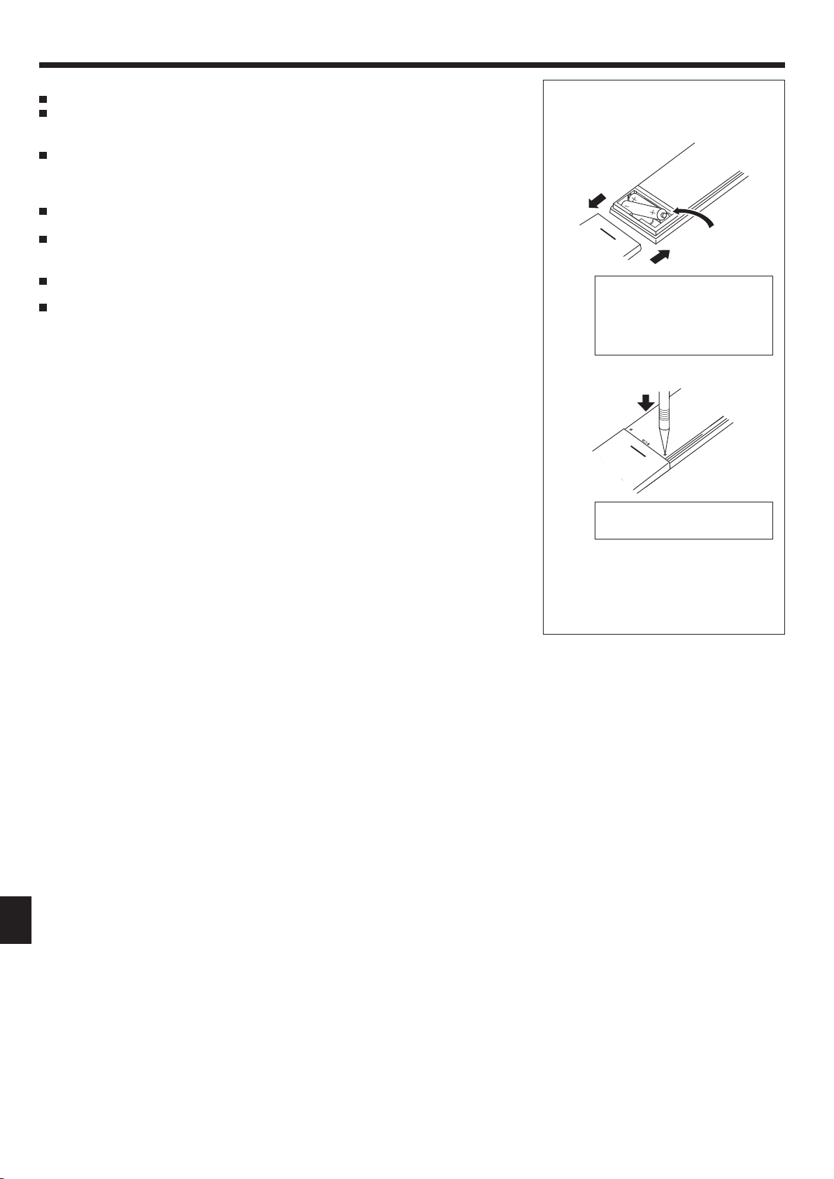
Battery installation/replacement
1. Remove the top cover, insert two LR6 AA
batteries, and then install the top cover.
1
2
Top cover
3
Two LR6 AA batteries
Insert the negative (–) end of
each battery first. Install the
batteries in the correct directions
(+, –)!
2. Press the Reset button.
Press the Reset button with an
object that has a narrow end.
After battery installation/replacement, please
set the clock. For details on how to set the
clock, refer to the operation manual included
with the remote controller.
EN
8
3. Operation
■
About the operation method, refer to the operation manual that comes with each remote controller.
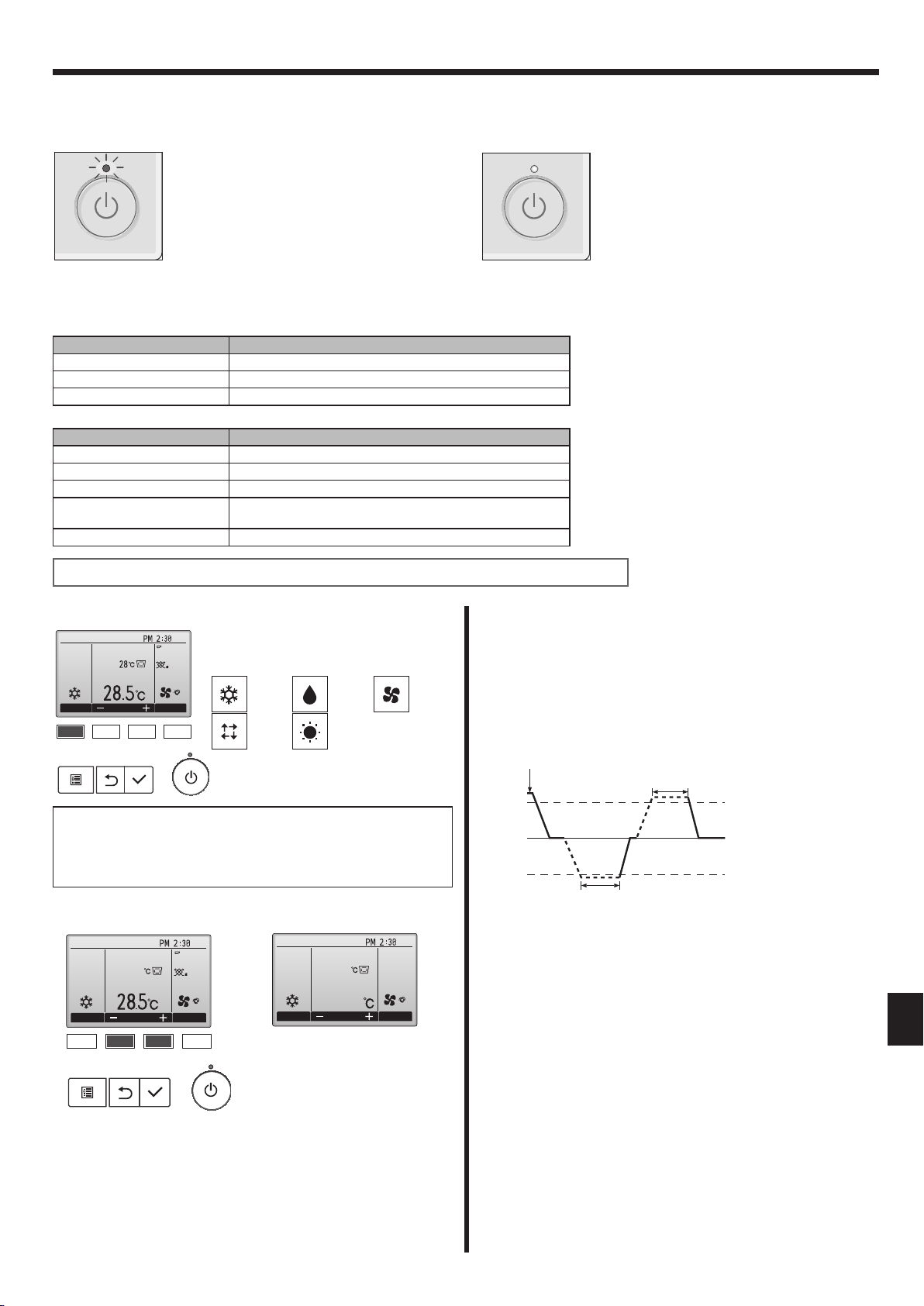
3.1. Turning ON/OFF
[ON] [OFF]
Press the [ON/OFF] button.
The ON/OFF lamp will light up in
green, and the operation will start.
Note:
Even if you press the ON/OFF button immediately after shutting down the operation is progress, the air conditioner will not start for about 3 minutes.
This is to prevent the internal components from being damaged.
■
Operation status memory
Remote controller setting
Operation mode Operation mode before the power was turned off
Preset temperature Preset temperature before the power was turned off
Fan speed Fan speed before the power was turned off
■
Settable preset temperature range
Operation mode Preset temperature range
Cool/Dry 19 ~ 30 ºC
Heat 17 ~ 28 ºC
Auto (Single set point) 19 ~ 28 ºC
Auto (Dual set points) [Cool] Preset temperature range for the Cool mode
[Heat] Preset temperature range for the Heat mode
Fan/Ventilation Not settable
Press the [ON/OFF] button again.
The ON/OFF lamp will come off,
and the operation will stop.
The settable temperature range varies with the model of outdoor units and remote controller.
3.2. Mode Selection
Fri
Room
Cool
Mode Temp. Fan
AutoSet temp.
Each pressing of the [F1] button cycles
through the following operation modes.
Select the desired operation mode.
Cool Dry Fan
Auto Heat
• Operation modes that are not available
Automatic operation (single set point)
■ According to a set temperature, cooling operation starts if the room
temperature is too hot and heating operation starts if the room
temperature is too cold.
■ During automatic operation, if the room temperature changes and
remains 1.5 °C or more above the set temperature for 3 minutes, the
air conditioner switches to cool mode. In the same way, if the room
temperature remains 1.5 °C or more below the set temperature for
3 minutes, the air conditioner switches to heat mode.
Cool mode
to the connected outdoor unit models will
not appear on the display.
What the blinking mode icon means
The mode icon will blink when other indoor units in the same refrigerant
system (connected to the same outdoor unit) are already operated in a
different mode. In this case, the rest of the unit in the same group can
only be operated in the same mode.
3.3. Temperature setting
<Cool, Dry, Heat, and Auto (single set point)>
Fri
Room
Cool
Mode Temp. Fan
28.5
AutoSet temp.
Cool
Mode Temp. Fan
(Centigrade in 0.5-degree increments)
Room
28.5
28.5
Example display
Fri
■ Because the room temperature is automatically adjusted in order to
maintain a fixed effective temperature, cooling operation is performed
AutoSet temp.
a few degrees warmer and heating operation is performed a few
degrees cooler than the set room temperature once the temperature is
reached (automatic energy-saving operation).
3 minutes (switches
from cooling to heating)
3 minutes (switches
from heating to cooling)
Set temperature +1.5°C
Set temperature
Set temperature -1.5°C
EN
Press the [F2] button to decrease the preset temperature, and press the
[F3] button to increase.
• Refer to the table on this page for the settable temperature range for
different operation modes.
• Preset temperature range cannot be set for Fan/Ventilation operation.
• Preset temperature will be displayed either in Centigrade in 0.5- or
1-degree increments, or in Fahrenheit, depending on the indoor unit
model and the display mode setting on the remote controller.
9
3. Operation
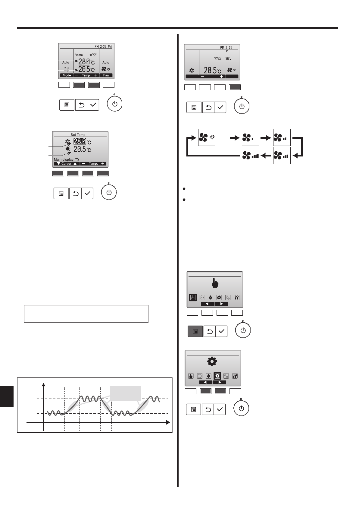
<Auto (dual set point) mode>
Preset temperature
for cooling
Preset temperature
for heating
26.5
1 The current preset temperatures will appear. Press the [F2] or [F3]
button to display the Settings screen.
Preset temperature
for cooling
Preset temperature
for heating
2 Press the [F1] or [F2] button to move the cursor to the desired
temperature setting (cooling or heating).
Press the [F3] button to decrease the selected temperature, and [F4]
to increase.
• Refer to the table on page 9 for the settable temperature range for
different operation modes.
• The preset temperature settings for cooling and heating in the
Auto (dual set point) mode are also used by the Cool/Dry and Heat
modes.
• The preset temperatures for cooling and heating in the Auto (dual
set point) mode must meet the conditions below:
• Preset cooling temperature is higher than preset heating temperature.
• The minimum temperature difference requirement between cooling and
heating preset temperatures (varies with the models of indoor units
connected) is met.
* If preset temperatures are set in a way that does not meet the minimum
temperature difference requirement, both preset temperatures will
automatically be changed within the allowable setting ranges.
3.4. Fan speed setting
Fri
Room
Cool
Mode Temp. Fan
28.5
AutoSet temp.
Each pressing of the [F4] button cycles through the following fan speeds.
Auto
• The available fan speeds depend on the models of connected indoor
units.
Note:
The number of available fan speeds depends on the type of unit
connected. Note also that some units do not provide an “Auto” setting.
In the following cases, the actual fan speed generated by the unit will differ
from the speed shown the remote controller display.
1. While the display is showing “STAND BY” or “DEFROST”.
2. When the temperature of the heat exchanger is low in the heat mode.
(e.g. immediately after heat operation starts)
3. In HEAT mode, when room temperature is higher than the temperature
setting.
4. When the unit is in DRY mode.
3.5. Airflow direction setting
3.5.1 Navigating through the Main menu
<Accessing the Main menu>
Main Main menu
Operation
Press the [MENU] button on the
Main display.
The Main menu will appear.
Navigating through the screens
• To return to the Main screen ...... [RETURN] button
<Auto operation (dual set point) mode>
When the operation mode is set to the Auto (dual set point) mode, two
preset temperatures (one each for cooling and heating) can be set.
Depending on the room temperature, indoor unit will automatically
operate in either the Cool or Heat mode and keep the room temperature
within the preset range.
The graph below shows the operation pattern of indoor unit operated in
the Auto (dual set point) mode.
Operation pattern during Auto (dual set point) mode
The room temperature
changes corresponding
to the change in the
outside temperature.
EN
Preset temp.
(COOL)
Preset temp.
(HEAT)
HEAT COOL HEAT COOL
Room
temperature
<Item selection>
Main Main menu
Initial setting
Press [F2] to move the cursor left.
Press [F3] to move the cursor right.
10
3. Operation
<Navigating through the pages>
Main
Main menu
Vane·Louver·Vent. (Lossnay)
High power
Timer
Weekly timer
OU silent mode
Main display:
Cursor Page
page
<Saving the settings>
OU silent mode
Mon Tue Wed Thu Fri Sat Sun
Start Stop Silent
-
Setting display:
day
<Exiting the Main menu screen>
Fri
Room
Cool
Mode Temp. Fan
AutoSet temp.
Press [F3] to go to the previous
page.
Press [F4] to go to the next page.
Select the desired item, and press
the [SELECT] button.
The screen to set the selected item
will appear.
Press the [RETURN] button to exit
the Main menu and return to the
Main display.
If no buttons are touched for
10 minutes, the screen will
automatically return to the Main
display. Any settings that have not
been saved will be lost.
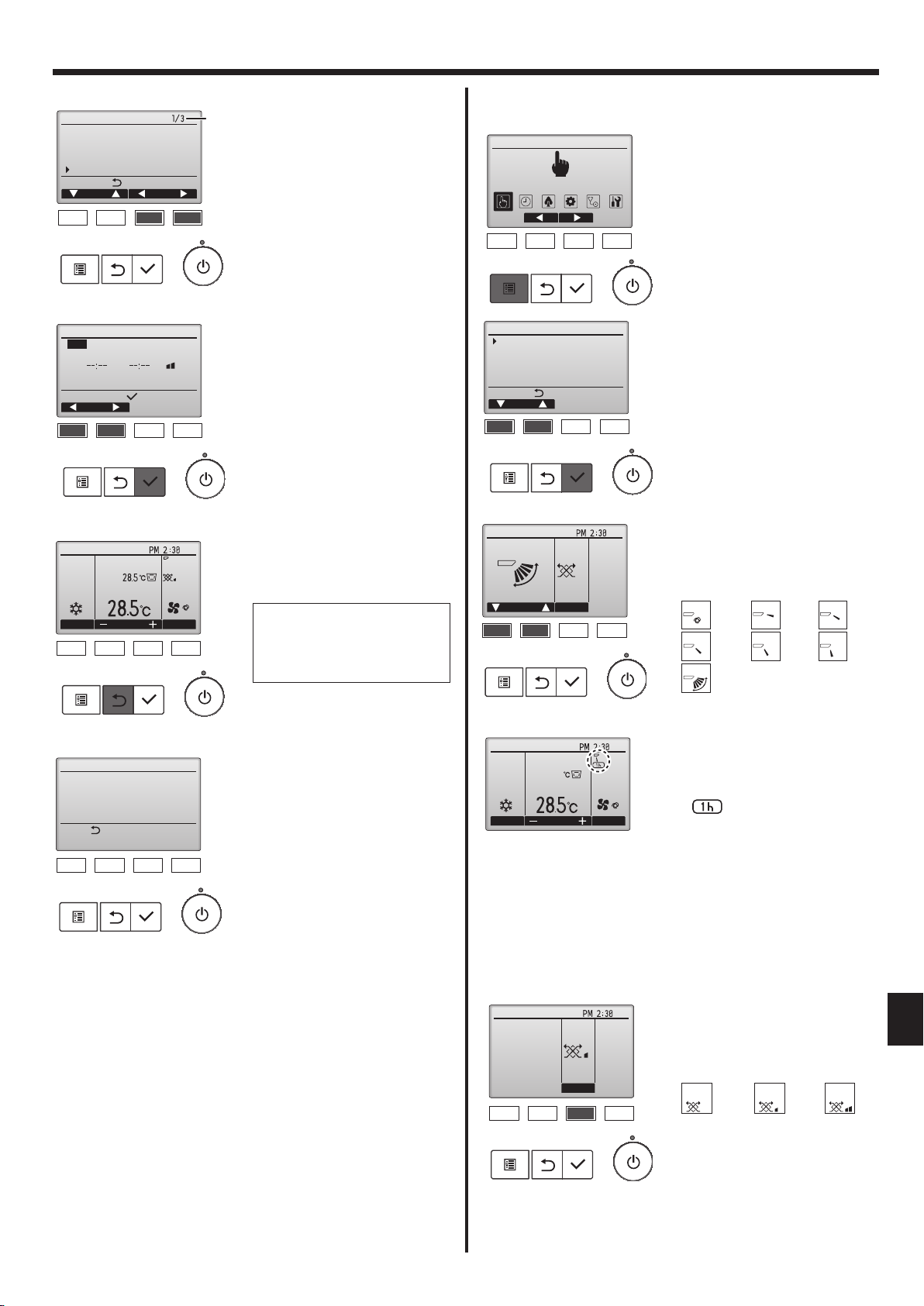
3.5.2 Vane·Vent. (Lossnay)
<Accessing the menu>
Main Main menu
Operation
Operation
Vane·Louver·Vent. (Lossnay)
High power
Comfort
Main menu:
Cursor
<Vane setting>
Fri
Swing Off
Vent.Vane
Select “Operation” from the Main
menu (refer to page 10), and press
the [SELECT] button.
Select “Vane•Louver•Vent. (Lossnay)” from the Operation menu, and
press the [SELECT] button.
Press the [F1] or [F2] button to go
through the vane setting options:
“Auto”, “Step 1”, “Step 2”, “Step 3”,
“Step 4”, “Step 5” and “Swing”.
Select the desired setting.
Auto
Swing
Auto
Swing
Step 1 Step 2
Step 4Step 3
Step 5
<Display of unsupported functions>
Title
Not available
Unsupported function
Return:
The message at left will appear if
the user selects a function not supported by the corresponding indoor
unit model.
Room
Cool
Mode Temp. Fan
28.5
<Vent. setting>
Low
Vent.
Select “Swing” to move the vanes
up and down automatically.
Fri
When set to “Step 1” through “Step
5”, the vane will be xed at the se-
AutoSet temp.
lected angle.
•
under the vane setting icon
This icon will appear when the
vane is set to “Step 2” to “Step 5”
and the fan operates at “Mid 1”
to “Low” speed during cooling or
dry operation (depends on the
model).
The icon will go off in an hour, and
the vane setting will automatically
change.
Fri
Press the [F3] button to go through
the ventilation setting options in the
EN
order of “Off ” , “Low” , and “High”.
* Settable only when LOSSNAY unit
is connected.
Off Low High
Off Low High
• The fan on some models of indoor
units may be interlocked with certain models of ventilation units.
11
3. Operation
<Returning to the Operation menu>
Operation
Vane·Louver·Vent. (Lossnay)
High power
Comfort
Main menu:
Cursor
Note:
During swing operation, the directional indication on the screen
●
does not change in sync with the directional vanes on the unit.
● Available directions depend on the type of unit connected.
In the following cases, the actual air direction will differ from the
●
direction indicated on the remote controller display.
1. While the display is in “STAND BY” or “DEFROST” states.
2. Immediately after starting heat mode (while the system is wait-
ing for the mode change to take effect).
3. In heat mode, when room temperature is higher than the tem-
perature setting.
Press the [RETURN] button to go
back to the Operation menu.
<[Manual] To Change the Airflow's Left/Right Direction>
* The louver button cannot be used.
• Stop the unit operation, hold the lever of the
louver, and adjust to the desired direction.
* Do not set to the inside direction when the
unit is in the cooling or drying mode because
there is a risk of condensation and water
dripping.
Caution:
To prevent falls, maintain a stable footing when operating the unit.
3.6. Ventilation
For LOSSNAY combination
■ The following 2 patterns of operation is available.
• Run the ventilator together with indoor unit.
• Run the ventilator independently.
Note: (for wireless remote controller)
● Running the ventilator independently is not available.
● No indication on the remote controller.
4. Timer
■ Timer functions are different by each remote controller.
■ For details on how to operate the remote controller, refer to the appropriate operation manual included with each remote controller.
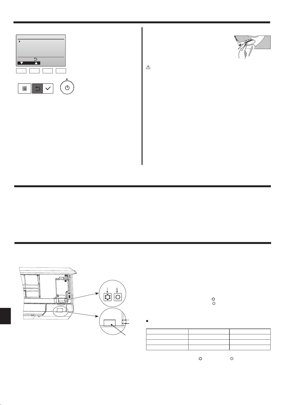
5. Emergency Operation for Wireless Remote-controller
When the remote controller cannot be used
When the batteries of the remote controller run out or the remote
controller malfunctions, the emergency operation can be done using the
emergency buttons on the grille.
A STANDBY lamp
B OPERATING lamp
C Emergency operation cooling switch
D Emergency operation heating switch
E Receiver
Starting operation
To operate the cooling mode, press the button C for more than 2 seconds.
•
•
To operate the heating mode, press the button D for more than 2 seconds.
• Lighting of the OPERATING lamp B means the start of operation.
Note:
Details of emergency mode are as shown below.
Details of EMERGENCY MODE are as shown below.
Operation mode COOL HEAT
Set temperature 24°C 24°C
Fan speed High High
Airflow direction Horizontal (Step 1) Downward (Step 5)
Stopping operation
• To stop operation, press the
than 2 seconds.
button C or the button D for more
EN
DC
B
A
E
12
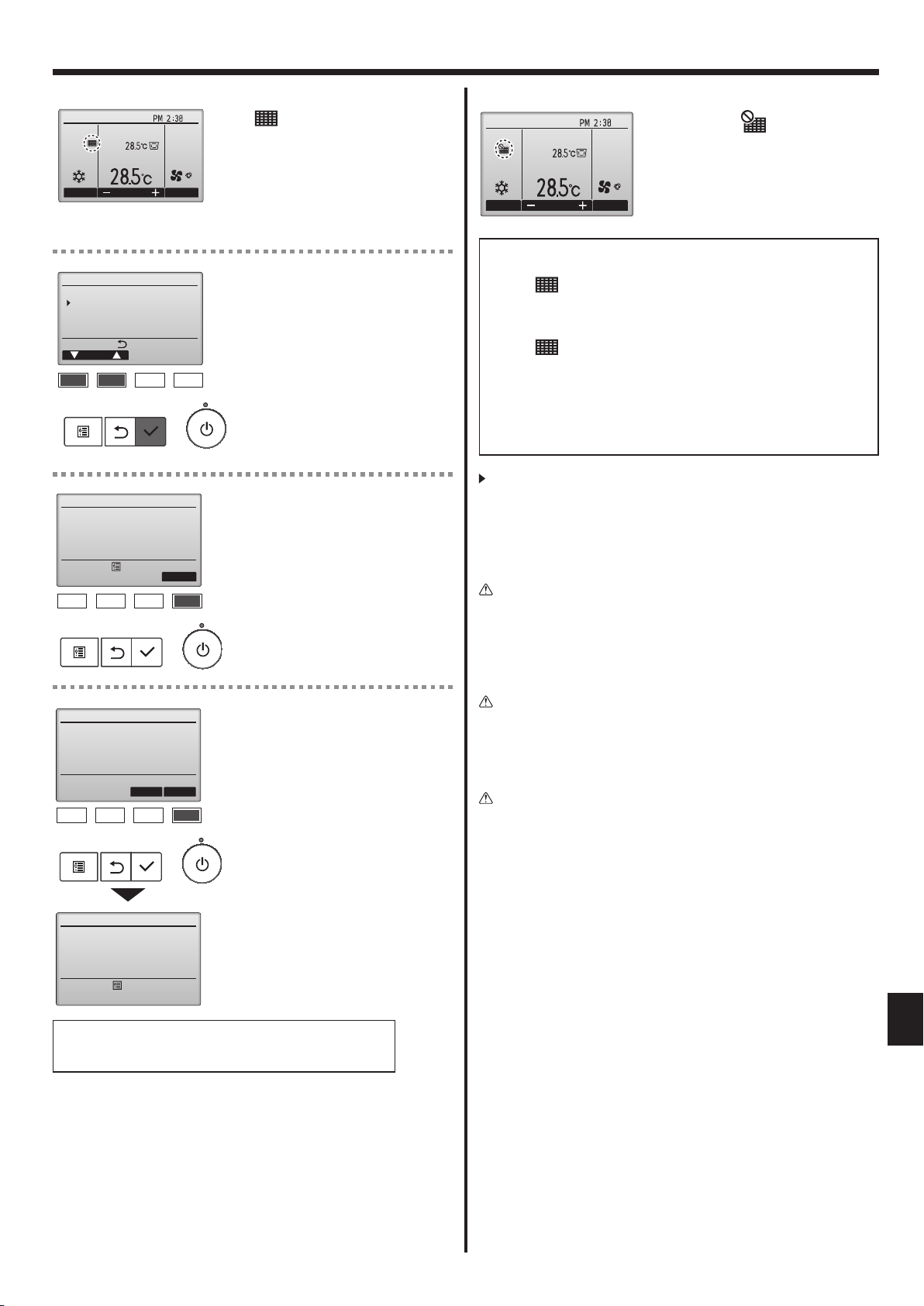
6. Care and Cleaning
■ Filter information
Fri
Room
Cool
Mode Temp. Fan
Maintenance menu
Error information
Filter information
Cleaning
Main display:
Cursor
AutoSet temp.
will appear on the Main display
in the Full mode when it is time to
clean the lters.
Wash, clean, or replace the lters
when this sign appears.
Refer to the indoor unit Instructions Manual for details.
Select “Filter information” from the
Maintenance menu, and press the
[SELECT] button.
Room
Cool
Mode Temp. Fan
AutoSet temp.
Fri
When the
Main display in the Full mode, the
system is centrally controlled and
the lter sign cannot be reset.
is displayed on the
If two or more indoor units are connected, filter cleaning timing for
each unit may be different, depending on the filter type.
The icon
will appear when the filter on the main unit is due for
cleaning.
When the filter sign is reset, the cumulative operation time of all units
will be reset.
The icon
is scheduled to appear after a certain duration of
operation, based on the premise that the indoor units are installed in a
space with ordinary air quality. Depending on the air quality, the filter
may require more frequent cleaning.
The cumulative time at which filter needs cleaning depends on the
model.
• This indication is not available for wireless remote controller.
Filter information
Press Reset button after
filter cleaning.
Main menu:
Filter information
Reset filter sign?
Filter information
Cancel
Reset
OK
Press the [F4] button to reset lter
sign.
Refer to the indoor unit Instructions
Manual for how to clean the lter.
Select “OK” with the [F4] button.
A conrmation screen will appear.
Cleaning the filters
• Clean the filters using a vacuum cleaner. If you do not have a vacuum
cleaner, tap the filters against a solid object to knock off dirt and dust.
• If the filters are especially dirty, wash them in lukewarm water. Take
care to rinse off any detergent thoroughly and allow the filters to dry
completely before putting them back into the unit.
Caution:
• Do not dry the filters in direct sunlight or by using a heat source,
such as an electric heater: this may warp them.
• Do not wash the filters in hot water (above 50°C), as this may
warp them.
• Make sure that the air filters are always installed. Operating the
unit without air filters can cause malfunction.
Caution:
• Before you start cleaning, stop operation and turn OFF the power
supply.
• Indoor units are equipped with filters to remove the dust of suckedin air. Clean the filters using the methods shown in the following
sketches.
Caution:
• In removing the filter, precautions must be taken to protect your
eyes from dust. Also, if you have to climb up on a stool to do the
job, be careful not to fall.
• When the filter is removed, do not touch the metallic parts inside
the indoor unit, otherwise injury may result.
Filter sign reset
Main menu:
Navigating through the screens
• To go back to the Main menu ................ [MENU] button
• To return to the previous screen ........... [RETURN] button
EN
13
6. Care and Cleaning
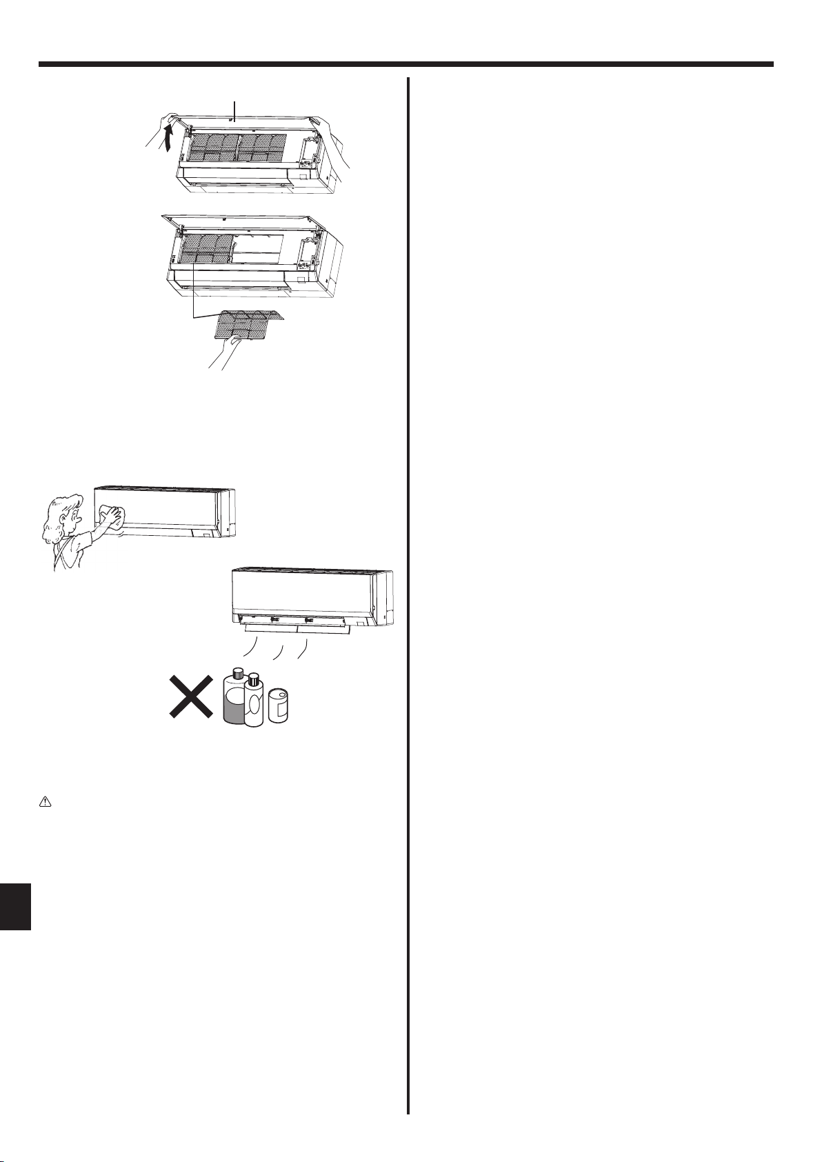
■ PKFY-P·VLM
B
A
1 Pull both the bottom corners of the grille to open the grille, then lift
the filter.
A Filter
B Grille
Cleaning the indoor unit
• Wipe the outside of the unit with a clean, dry, soft cloth.
• Clean off any oil stains or finger marks using a neutral household
detergent (such as dishwashing liquid or laundry detergent).
Caution:
Never use gasoline, benzene, thinner, scouring powder or any type
of non-neutral detergent, as these substances may damage the
unit’s case.
EN
14
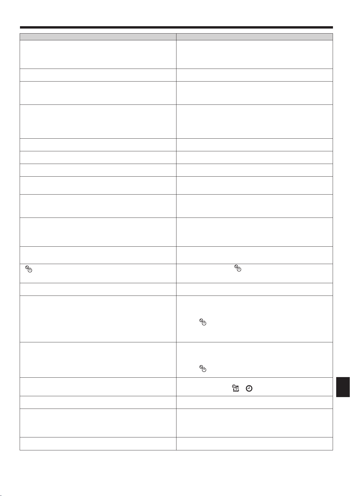
7. Troubleshooting
Having trouble? Here is the solution. (Unit is operating normally.)
Air conditioner does not heat or cool well.
When heating operation starts, warm air does not blow from the indoor
unit soon.
During heat mode, the air conditioner stops before the set room
temperature is reached.
Airflow up/down direction changes during operation or airflow up/down
direction cannot be set.
When the airflow up/down direction is changed, the vanes always move
up and down past the set position before finally stopping at the position.
A flowing water sound or occasional hissing sound is heard.
A cracking or creaking sound is heard.
The room has an unpleasant odor.
A white mist or vapor is emitted from the indoor unit.
Water or vapor is emitted from the outdoor unit.
The air conditioner does not operate even though the ON/OFF button
is pressed. The operation mode display on the remote controller
disappears.
“
” appears in the remote controller display.
When restarting the air conditioner soon after stopping it, it does not
operate even though the ON/OFF button is pressed.
Air conditioner operates without the ON/OFF button being pressed.
Air conditioner stops without the ON/OFF button being pressed.
Remote controller timer operation cannot be set.
“PLEASE WAIT” appears in the remote controller display.
An error code appears in the remote controller display.
Draining water or motor rotation sound is heard.
■ Clean the filter. (Airflow is reduced when the filter is dirty or clogged.)
■ Check the temperature adjustment and adjust the set temperature.
■ Make sure that there is plenty of space around the outdoor unit. Is the
indoor unit air inlet or outlet blocked?
■ Has a door or window been left open?
■ Warm air does not blow until the indoor unit has sufficiently warmed
up.
■ When the outdoor temperature is low and the humidity is high,
frost may form on the outdoor unit. If this occurs, the outdoor unit
performs a defrosting operation. Normal operation should begin after
approximately 10 minutes.
■ During cool mode, the vanes automatically move to the step 1 position
after 1 hour when the vane is set to “Step 2” to “Step 5”. This is to
prevent water from forming and dripping from the vanes.
■ During heat mode, the vanes automatically move to the step 1
position when the airflow temperature is low or during defrosting
mode.
■ When the airflow up/down direction is changed, the vanes move to the
set position after detecting the base position.
■ These sounds can be heard when refrigerant is flowing in the air
conditioner or when the refrigerant flow is changing.
■ These sounds can be heard when parts rub against each due to
expansion and contraction from temperature changes.
■ The indoor unit draws in air that contains gases produced from the
walls, carpeting, and furniture as well as odors trapped in clothing,
and then blows this air back into the room.
■ If the indoor temperature and the humidity are high, this condition may
occur when operation starts.
■ During defrosting mode, cool airflow may blow down and appear like a
mist.
■ During cool mode, water may form and drip from the cool pipes and
joints.
■ During heat mode, water may form and drip from the heat exchanger.
■ During defrosting mode, water on the heat exchanger evaporates and
water vapor may be emitted.
■ Is the power switch of the indoor unit turned off? Turn on the power
switch.
■ During central control, “ ” appears in the remote controller display
and air conditioner operation cannot be started or stopped using the
remote controller.
■ Wait approximately 3 minutes.
(Operation has stopped to protect the air conditioner.)
■ Is the on timer set?
Press the ON/OFF button to stop operation.
■ Is the air conditioner connected to a central remote controller?
Consult the concerned people who control the air conditioner.
■ Does “ ” appear in the remote controller display?
Consult the concerned people who control the air conditioner.
■ Has the auto recovery feature from power failures been set?
Press the ON/OFF button to stop operation.
■ Is the off timer set?
Press the ON/OFF button to restart operation.
■ Is the air conditioner connected to a central remote controller?
Consult the concerned people who control the air conditioner.
■ Does “ ” appear in the remote controller display?
Consult the concerned people who control the air conditioner.
■ Are timer settings invalid?
If the timer can be set, or appears in the remote controller
display.
■ The initial settings are being performed. Wait approximately 3
minutes.
■ The protection devices have operated to protect the air conditioner.
■ Do not attempt to repair this equipment by yourself.
Turn off the power switch immediately and consult your dealer. Be
sure to provide the dealer with the model name and information that
appeared in the remote controller display.
■ When cooling operation stops, the drain pump operates and then
stops. Wait approximately 3 minutes.
EN
15
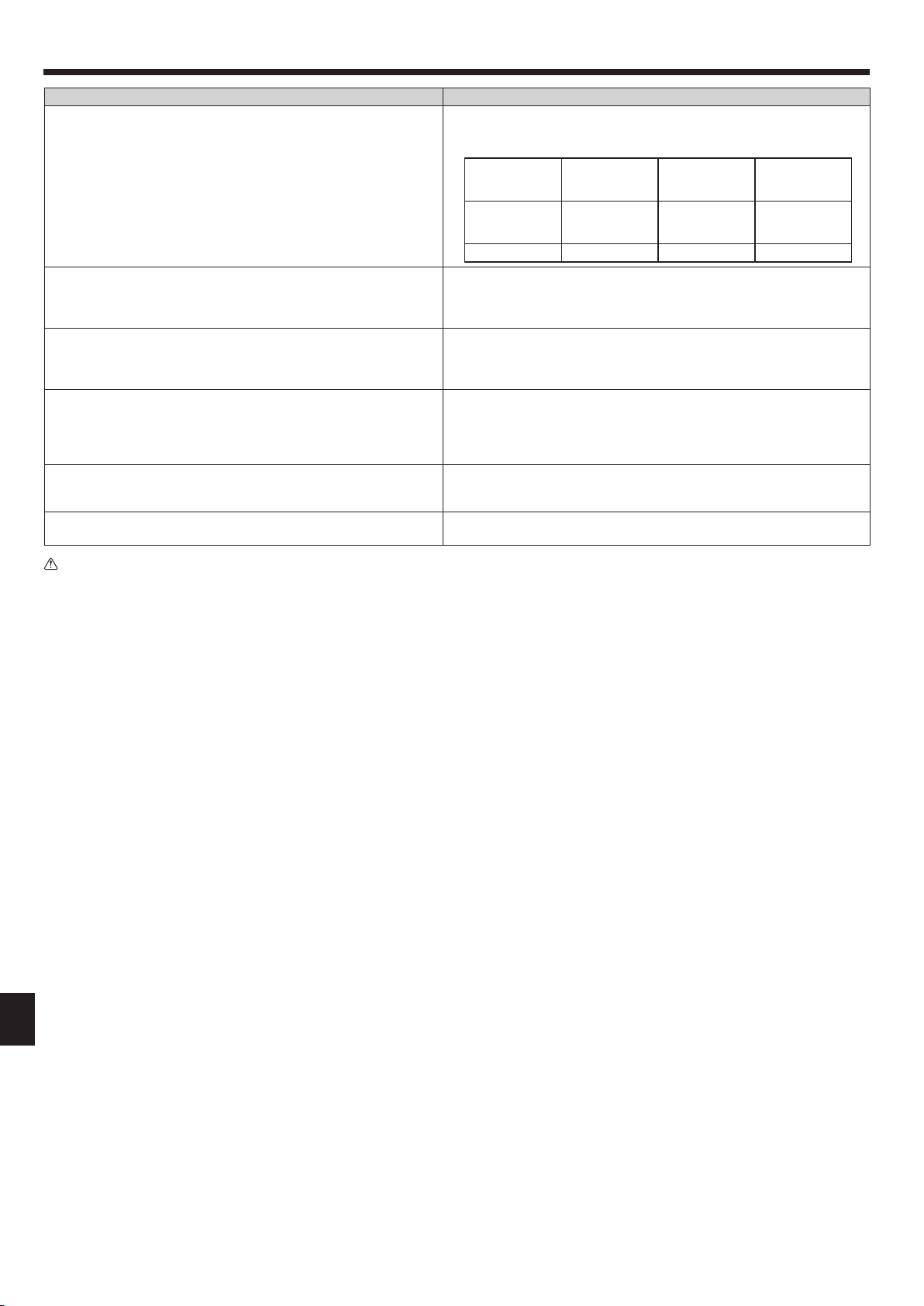
7. Troubleshooting
Having trouble? Here is the solution. (Unit is operating normally.)
Noise is louder than specifications.
Nothing appears in the wireless remote controller display, the display
is faint, or signals are not received by the indoor unit unless the
remote controller is close.
The operation lamp near the receiver for the wireless remote
controller on the indoor unit is blinking.
Warm air blows from the indoor unit intermittently when heating mode
is off or during fan mode.
The wireless remote controller does not operate (the indoor unit
beeps 4 times).
Refrigerant noise is heard or warm air comes out from the suspended
indoor unit.
■ The indoor operation sound level is affected by the acoustics of the
particular room as shown in the following table and will be higher than
the noise specification, which was measured in an echo-free room.
High sound-
absorbing
rooms
Location
examples
Noise levels 3 to 7 dB 6 to 10 dB 9 to 13 dB
Broadcasting
studio, music
room, etc.
Normal rooms
Reception
room, hotel
lobby, etc.
Low sound-
absorbing
rooms
Office, hotel
room
■ The batteries are low.
Replace the batteries and press the Reset button.
■ If nothing appears even after the batteries are replaced, make sure that
the batteries are installed in the correct directions (+, –).
■ The self diagnosis function has operated to protect the air conditioner.
■ Do not attempt to repair this equipment by yourself.
Turn off the power switch immediately and consult your dealer. Be sure
to provide the dealer with the model name.
■ When another indoor unit is operating in heating mode, the control valve
opens and closes occasionally to maintain stability in the air conditioning
system. This operation will stop after a while.
* If this will cause an undesirable rise in the room temperature in small
rooms, etc., stop the operation of the indoor unit temporarily.
■ Switch the auto mode setting to the AUTO (single set point) mode or
AUTO (dual set point) mode. For details, refer to the included Notice (A5
sheet) or the Installation Manual.
■ A small amount of refrigerant flows into the suspended indoor unit while
other indoor units are in operation at HEAT mode.
Warning:
If the air conditioner operates but does not cool or heat (depending on model) the room, consult your dealer since there may be a
refrigerant leak. Be sure to ask the service representative whether there is refrigerant leakage or not when repairs are carried out.
The refrigerant charged in the air conditioner is safe. Refrigerant normally does not leak. However, if refrigerant gas leaks indoors, and
comes into contact with the fire of a fan heater, space heater, stove, etc., harmful substances will be generated.
EN
16
 Loading...