

Mitsubishi Electric PKFY-P15VBM-E, PKFY-P15VBM-ER2, PKFY-P20VBM-ER1, PKFY-P20VBM-ER2, PKFY-P25VBM-E Service Manual
...
TECHNICAL & SERVICE MANUAL
CONTENTS
1. TECHNICAL CHANGES .........................2
2. SAFETY PRECAUTION
..........................
2
3. PART NAMES AND FUNCTIONS
..........
6
4. SPECIFICATION
.....................................
9
5. OUTLINES AND DIMENSIONS
............
11
6. WIRING DIAGRAM
...............................
12
7. REFRIGERANT SYSTEM DIAGRAM
........
14
8. TROUBLESHOOTING
..........................
14
9. DISASSEMBLY PROCEDURE
.............
22
Indoor unit
[Model names] [Service Ref.]
PKFY-P15VBM-E
PKFY-P15VBM-ER2
PKFY-P20VBM-E
PKFY-P20VBM-ER1
PKFY-P20VBM-ER2
PKFY-P25VBM-E
PKFY-P25VBM-ER1
PKFY-P25VBM-ER2
No. OCH418
REVISED EDITION-B
INDOOR UNIT
SPLIT-TYPE, HEAT PUMP AIR CONDITIONERS
R407C R22R410A
Note:
• This manual describes only
service data of the indoor
units.
• RoHS compliant products
have <G> mark on the
spec name plate.
November 2011
Model name
indication
PARTS CATALOG (OCB418)
Revision:
• PKFY-P15/20/25VBM-ER2
have been added in
REVISED EDITION-B.
• Some descriptions have
been modified.
• Please void OCH418
REVISED EDITION-A.
PKFY-P15VBM-E
PKFY-P20VBM-E
PKFY-P25VBM-E
2
1
TECHNICAL CHANGES
Cautions for units utilizing refrigerant R407C
CAUTIONS RELATED TO NEW REFRIGERANT
Do not use the existing refrigerant piping.
The old refrigerant and lubricant in the existing piping
contain a large amount of chlorine which may cause the
lubricant deterioration of the new unit.
Use “low residual oil piping”
If there is a large amount of residual oil (hydraulic oil, etc.)
inside the piping and joints, deterioration of the lubricant
will result.
Use ESTR , ETHER or HAB as the lubricant to
coat flares and flange connection parts.
If large amount of mineral oil enters, that can cause
deterioration of refrigerant oil etc.
Use liquid refrigerant to charge the system.
If gas refrigerant is used to seal the system, the composition
of the refrigerant in the cylinder will change and performance
may drop.
Do not use a refrigerant other than R407C.
If another refrigerant (R22, etc.) is used, the chlorine in the
refrigerant may cause the lubricant deterioration.
Use a vacuum pump with a reverse flow check valve.
The vacuum pump oil may flow back into the refrigerant
cycle and cause the lubricant deterioration.
Store the piping to be used indoors during
installation and both ends sealed until just
before brazing.
(Store elbows and other joints in a plastic bag.)
If dust, dirt, or water enters the refrigerant cycle,
deterioration of the oil and compressor trouble may result.
Ventilate the room if refrigerant leaks during
operation. If refrigerant comes into contact with
a flame, poisonous gases will be released.
Use the specified refrigerant only.
Never use any refrigerant other than that specified.
Doing so may cause a burst, an explosion, or fire when the
unit is being used, serviced, or disposed of.
Correct refrigerant is specified in the manuals and on the
spec labels provided with our products.
We will not be held responsible for mechanical failure,
system malfunction, unit breakdown or accidents caused
by failure to follow the instructions.
2
SAFETY PRECAUTION
PKFY-P15VBM-E PKFY-P15VBM-ER2
PKFY-P20VBM-ER1 PKFY-P20VBM-ER2
PKFY-P25VBM-ER1 PKFY-P25VBM-ER2
HEAT EXCHANGER and WATER CUT have been changed.
PKFY-P20VBM-E PKFY-P20VBM-ER1
PKFY-P25VBM-E PKFY-P25VBM-ER1
INDOOR CONTROLLER BOARD (I.B.) has been changed.
OCH418B
33
[3] Service tools
Use the below service tools as exclusive tools for R407C refrigerant.
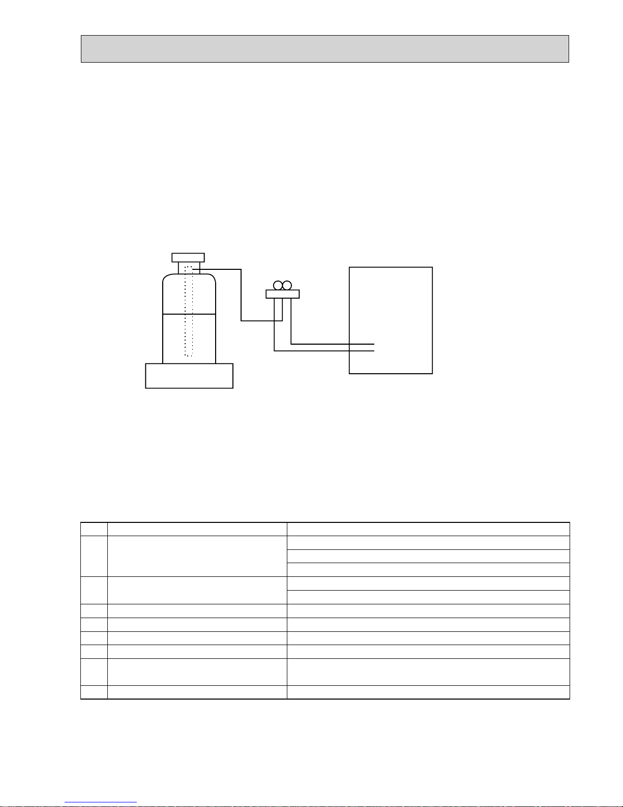
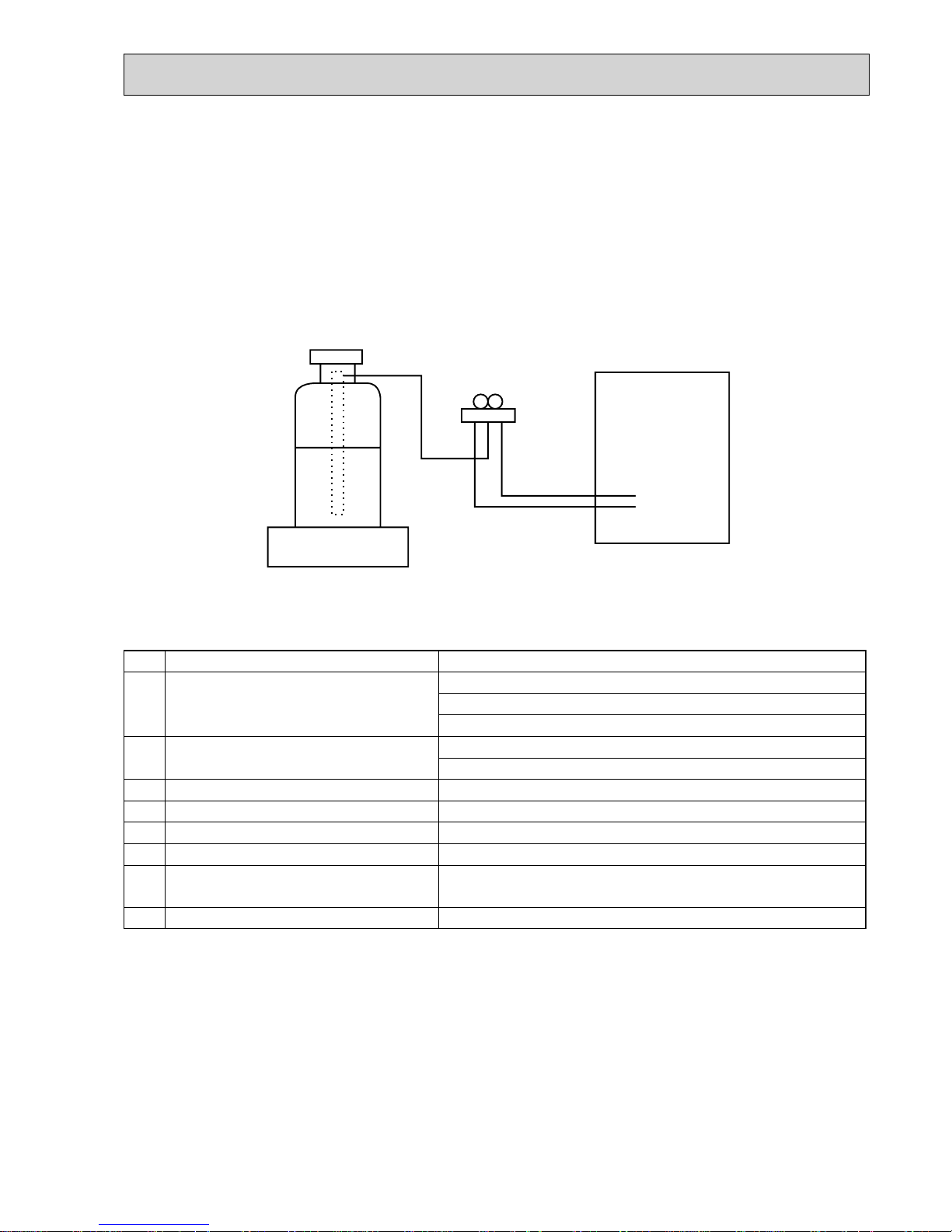
[2] Refrigerant recharging
(1) Refrigerant recharging process
1 Direct charging from the cylinder.
·R407C cylinder available on the market has a syphon pipe.
·Leave the syphon pipe cylinder standing and recharge it.
(By liquid refrigerant)
(2) Recharge in refrigerant leakage case
·After recovering all the refrigerant in the unit, proceed to working.
·Do not release the refrigerant in the air.
·After completing the repair service, recharge the cycle with the specified amount of
liquid refrigerant.
Gravimeter
Unit
No.
Tool name
Specifications
Gauge manifold ·Only for R407C
·Use the existing fitting SPECIFICATIONS. (UNF7/16)
·Use high-tension side pressure of 3.43MPa·G or over.
Charge hose ·Only for R407C
·Use pressure performance of 5.10MPa·G or over.
—
Electronic scale
Gas leak detector ·Use the detector for R134a or R407C.
Adapter for reverse flow check ·Attach to vacuum pump.
—
—
Refrigerant charge base
Refrigerant cylinder ·For R407C ·Top of cylinder (Brown)
·Cylinder with syphon
Refrigerant recovery equipment
[1] Cautions for service
·After recovering the all refrigerant in the unit, proceed to working.
·Do not release refrigerant in the air.
·After completing the repair service, recharge the cycle with the specified amount of liquid refrigerant.
OCH418B
4
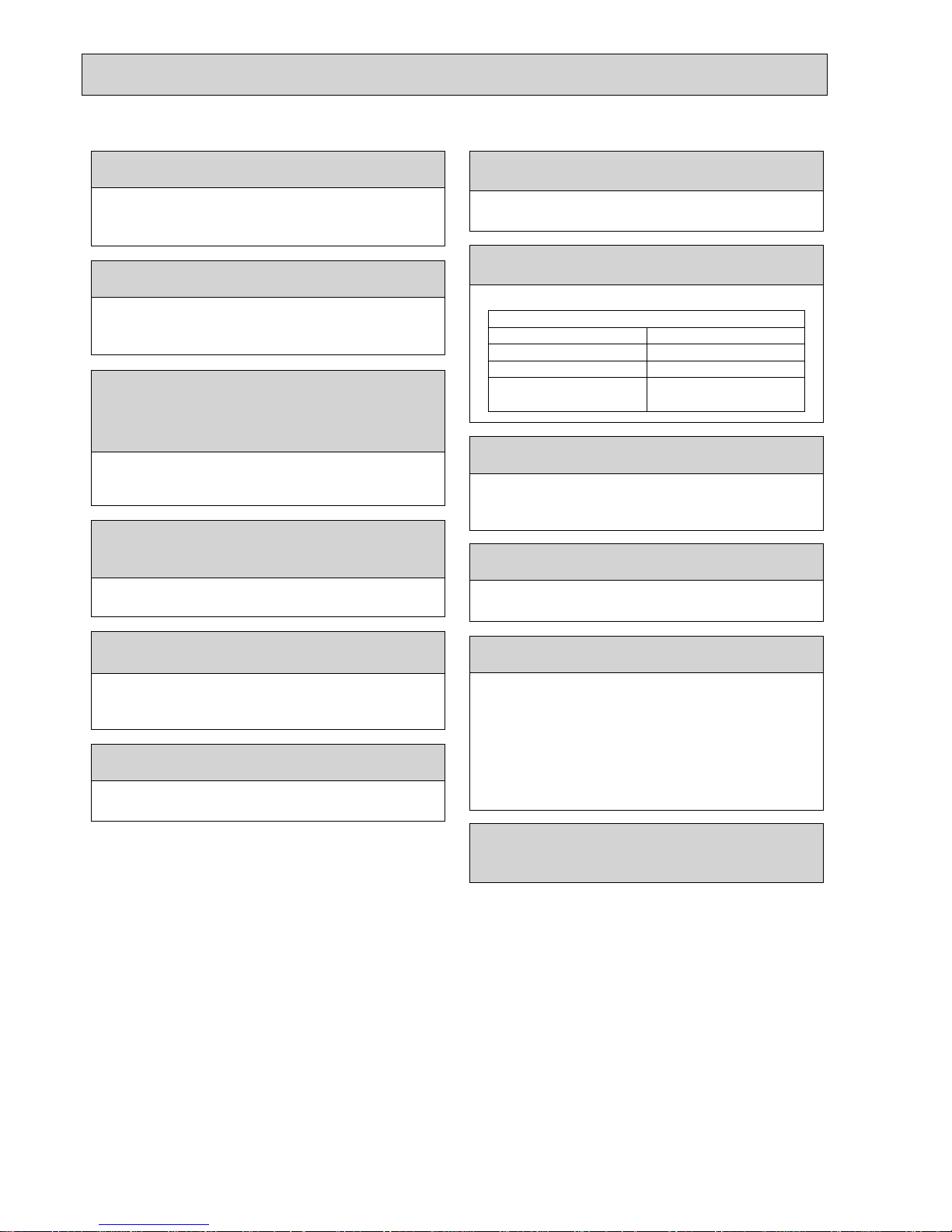
Cautions for units utilizing refrigerant R410A
Store the piping to be used indoors during
installation and both ends of the piping sealed
until just before brazing. (Leave elbow joints, etc.
in their packaging.)
Use ester oil, ether oil or alkylbenzene oil (small
amount) as the refrigerant oil applied to flares
and flange connections.
Charge refrigerant from liquid phase of gas
cylinder.
If the refrigerant is charged from gas phase, composition
change may occur in refrigerant and the efficiency will be
lowered.
Do not use refrigerant other than R410A.
If other refrigerant (R22 etc.) is used, chlorine in refrigerant can cause deterioration of refrigerant oil etc.
Use a vacuum pump with a reverse flow check
valve.
Vacuum pump oil may flow back into refrigerant cycle and
that can cause deterioration of refrigerant oil etc.
Use the following tools specifically designed for
use with R410A refrigerant.
The following tools are necessary to use R410A refrigerant.
Handle tools with care.
If dirt, dust or moisture enters into refrigerant cycle, that can
cause deterioration of refrigerant oil or malfunction of compressor.
Do not use a charging cylinder.
If a charging cylinder is used, the composition of refrigerant will change and the efficiency will be lowered.
Flare tool
Electronic refrigerant
charging scale
Vacuum pump adaptor
Size adjustment gauge
Gauge manifold
Torque wrench
Gas leak detector
Charge hose
Tools for R410A
If dirt, dust or moisture enters into refrigerant cycle, that can
cause deterioration of refrigerant oil or malfunction of compressor.
If large amount of mineral oil enters, that can cause deterioration of refrigerant oil etc.
Do not use the existing refrigerant piping.
The old refrigerant and lubricant in the existing piping
contains a large amount of chlorine which may cause the
lubricant deterioration of the new unit.
Use “low residual oil piping”
If there is a large amount of residual oil (hydraulic oil, etc.)
inside the piping and joints, deterioration of the lubricant
will result.
Ventilate the room if refrigerant leaks during
operation. If refrigerant comes into contact with
a flame, poisonous gases will be released.
Use the specified refrigerant only.
Never use any refrigerant other than that specified.
Doing so may cause a burst, an explosion, or fire when the
unit is being used, serviced, or disposed of.
Correct refrigerant is specified in the manuals and on the
spec labels provided with our products.
We will not be held responsible for mechanical failure,
system malfunction, unit breakdown or accidents caused
by failure to follow the instructions.
OCH418B
5
[1] Cautions for service
(1) Perform service after collecting the refrigerant left in the unit completely.
(2) Do not release refrigerant in the air.
(3) After completing service, charge the cycle with specified amount of refrigerant.
(4) When performing service, install a filter drier simultaneously.
Be sure to use a filter drier for new refrigerant.
[2] Additional refrigerant charge
When charging directly from cylinder
· Check that cylinder for R410A on the market is syphon type.
· Charging should be performed with the cylinder of syphon stood vertically. (Refrigerant is charged from liquid phase.)
Gravimeter
Unit
[3] Service tools
Use the below service tools as exclusive tools for R410A refrigerant.
No. Tool name Specifications
1
Gauge manifold · Only for R410A
· Use the existing fitting
specifications
. (UNF1/2)
· Use high-tension side pressure of 5.3 MPa·G or over.
2
Charge hose · Only for R410A
· Use pressure performance of 5.09 MPa·G or over.
3
Electronic scale
—
4
Gas leak detector · Use the detector for R134a, R407C or R410A.
5
Adaptor for reverse flow check · Attach on vacuum pump.
6
Refrigerant charge base
—
7
Refrigerant cylinder · Only for R410A Top of cylinder (Pink)
Cylinder with syphon
8
Refrigerant recovery equipment
—
OCH418B
6
3
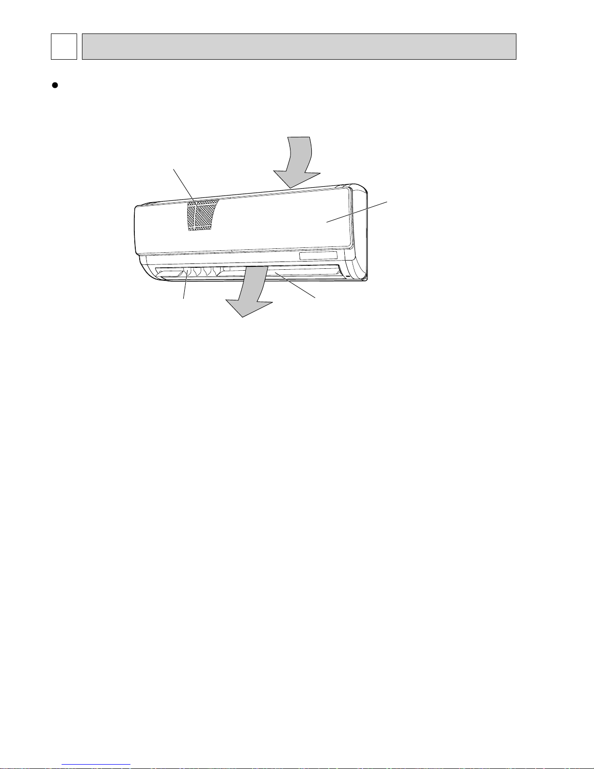
PART NAMES AND FUNCTIONS
Indoor unit
Filter
Grille
Louver
Air outlet
Air intake
Vane
OCH418B
77
°F°C
°F°C
ERROR CODE
AFTER
TIMER
TIME SUN MON TUE WED THU FRI SAT
ON
OFF
Hr
AFTER
FILTER
FUNCTION
ONLY1Hr.
WEEKLY
SIMPLE
AUTO OFF
PAR-21MAA
ON/OFF
FILTER
CHECK
OPERATION
CLEAR
TEST
TEMP.
MENU
BACK DAY
MONITOR/SET
CLOCK
ON/OFF
●
●
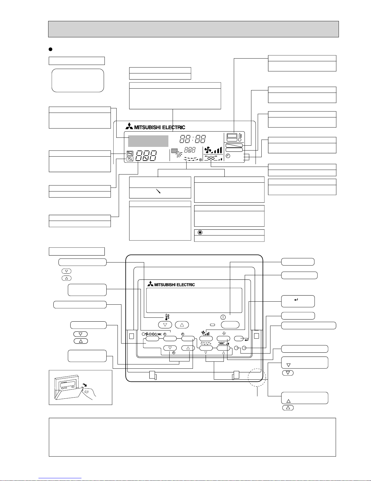
Display Section
For purposes of this explanation,
all parts of the display are shown.
During actual operation, only
the relevant items will be lit.
Identifies the current operation
Shows the operating mode, etc.
*Multilanguage display is available.
“Centrally Controlled” indicator
Indicates that operation from the
remote controller has been prohibited by a master controller.
“Timer is Off” indicator
Indicates that the timer is off.
Temperature Setting
Shows the target temperature.
Day-of-Week
Shows the current day of the week.
Time/Timer Display
Shows the current time, unless the simple or Auto Off
timer is set.
If the simple or Auto Off timer is set, the time to be
switched off is shown.
“Sensor” indication
Displays when the remote controller
sensor is used.
“Locked” indicator
Indicates that remote controller buttons have been locked.
“Clean The Filter” indicator
To be displayed on when it is time to
clean the filter.
Timer indicators
The indicator comes on if the corresponding timer is set.
Up/Down Air Direction indicator
The indicator shows the direction of the outcoming airflow.
“One Hour Only” indicator
Room Temperature display
Shows the room temperature. The room
temperature display range is 8–39.
The display blinks if the temperature
is less than 8 or 39 or more.
Louver display
Indicates the action of the swing louver.
Does not appear if the louver is not
running.
(Power On indicator)
Indicates that the power is on.
Fan Speed indicator
Shows the selected fan speed.
Ventilation indicator
Appears when the unit is running in
Ventilation mode.
Operation Section
Temperature setting buttons
Down
Up
Timer Menu button
(Monitor/Set button)
Mode button (Return button)
Set Time buttons
Back
Ahead
Timer On/Off button
(Set Day button)
Opening the
cover
ON/OFF button
Fan Speed button
Filter button
(<Enter> button)
Test Run button
Check button (Clear button)
Airflow Up/Down button
Louver button
( Operation button)
T o return operation
number
Ventilation button
( Operation button)
To go to next operation
number
Note:
“PLEASE WAIT” message
This message is displayed for approximately 3 minutes when power is supplied to the indoor unit or when the unit is recovering from a power failure.
“NOT AVAILABLE” message
This message is displayed if an invalid button is pressed (to operate a function that the indoor unit does not have).
If a single remote controller is used to operate multiple indoor units simultaneously that are different types, this message will not be displayed as
far as any of the indoor units is equipped with the function.
Built-in temperature sensor
Displays if the airflow is set to
Low or downward during COOL
or DRY mode. (Operation varies
according to model.)
The indicator goes off in one hour,
at which time the airflow direction
also changes.
Wired remote controller
OCH418B
8
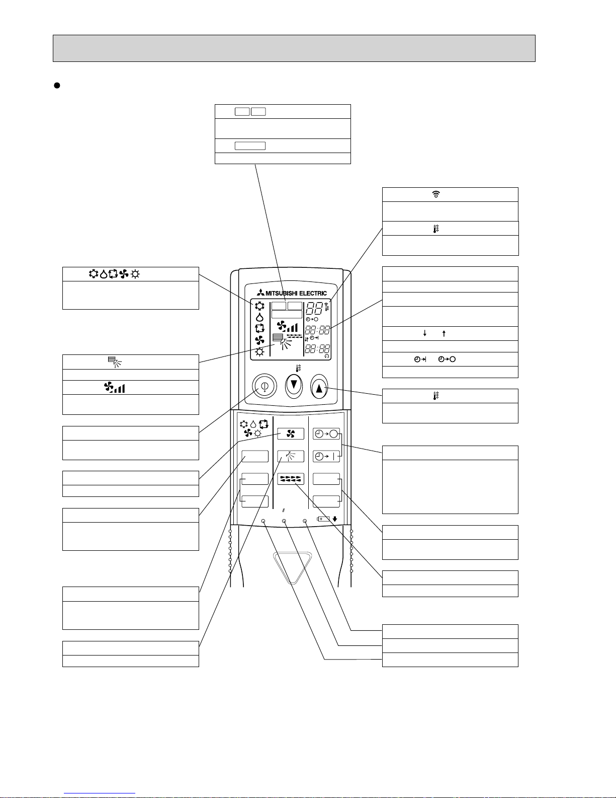
Wireless remote controller
ON/OFF TEMP
FAN
VANE
TEST RUN
AUTO STOP
AUTO START
h
min
LOUVER
MODE
CHECK
RESETSET CLOCK
MODEL SELECT
NOT AV AILABLE
CHECK
TEST RUN
°C
AMPM
AMPM
VANE CONTROL button
Used to change the air flow direction.
CLOCK button
RESET button
SET button
ON/OFF button
The unit is turned ON and OFF alternately
each time the button is pressed.
LOUVER button
Changes left/right airflow direction.
(Not available for this model.)
MODE SELECT button
Used to switch the operation mode between
cooling, drying, fan, heating and auto mode.
CHECK-TEST RUN button
Only press this button to perform an
inspection check or test operation.
Do not use it for normal operation.
FAN SPEED SELECT button
Used to change the fan speed.
TIMER display
Displays when in timer operation or when
setting timer.
button
SET TEMPERATURE button sets any desired
room temperature.
CLOCK display
Displays the current time.
“ ” “ ” display
Displays the order of timer operation.
“ ” “ ” display
Displays whether timer is on or off.
+ In case the outdoor unit is cool only type,
the heating and auto mode are not
available.
Buttons used to set the “hour and minute” of
the current time and timer settings.
h and min buttons
display
display
FAN SPEED display indicates which fan
speed has been selected.
display
The vertical direction of air flow is indicated.
display
Blinks when model is selected.
display
display
CHECK and TEST RUN display indicate that
the unit is being checked or test-run.
display
OPERATION MODE display
Operation mode display indicates which
operation mode is in effect.
TIMER CONTROL buttons
AUTO STOP (OFF timer): when this switch is
set, the air conditioner will be automatically
stopped at the preset time.
AUTO START (ON timer): when this switch is
set, the air conditioner will be automatically
started at the preset time.
MODEL SELECT
CHECK
TEST RUN
SET TEMP. display indicates the set desired
temperature.
Lights up while the signal is transmitted to
the indoor unit when the button is pressed.
OCH418B
99
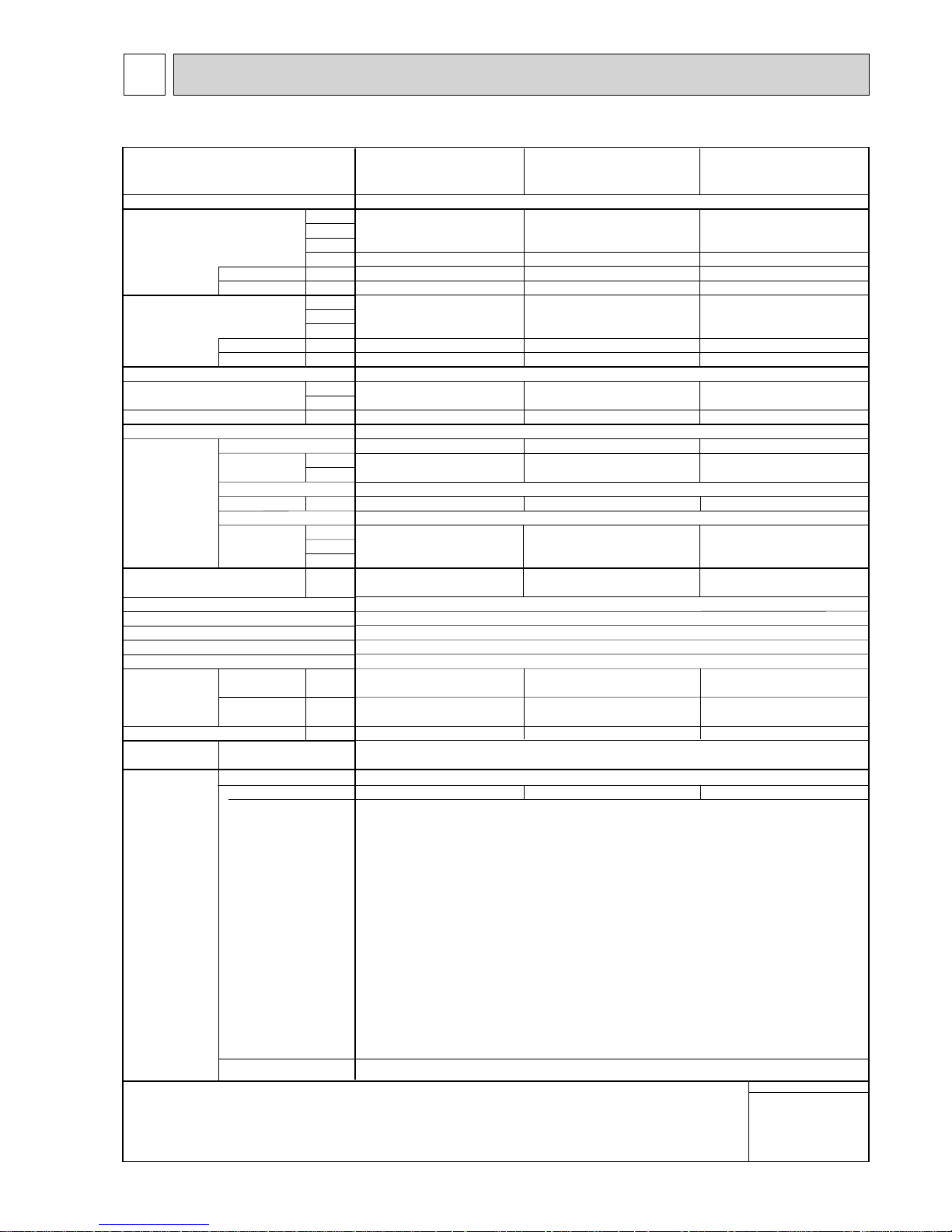
*1 Nominal cooling conditions
Note :
Indoor :
Outdoor :
Pipe length :
Level difference :
27°CDB/19°CWB (81°FDB/66°FWB)
35°CDB (95°FDB)
7.5 m (24-9/16 ft)
0 m (0 ft)
*2 Nominal cooling conditions
27°CDB/19.5°CWB (81°FDB/67°FWB)
35°CDB (95°FDB)
5 m (16-3/8 ft)
0 m (0 ft)
*3 Nominal heating conditions
Unit converter
20°CDB (68°FDB)
7°CDB/6°CWB (45°FDB/43°FWB)
7.5 m (24-9/16 ft)
0 m (0 ft)
* Due to continuing improvement, above specification may be subject to change without notice.
* Nominal conditions *
1, *3 are subject to JIS B8615-1.
kcal/h = kW × 860
Btu/h = kW × 3,412
cfm = m
3
/min × 35.31
lb = kg/0.4536
*Above specification data is
subject to rounding variation.
Service ref.
Power source
Cooling capacity
(Nominal)
Heating capacity
(Nominal )
External finish
External dimension H x W x D
Net weight
Heat exchanger
Fan
Noise level (Low-Mid2-Mid1-High)
(measured in anechoic room)
Insulation material
Air filter
Protection device
Refrigerant control device
Connectable outdoor unit
Diameter of
refrigerant pipe
Field drain pipe size
Standard
attachment
Remark
Power input
Current input
Power input
Current input
Type x Quantity
External
static press.
Motor type
Motor output
Driving mechanism
Airflow rate
(Low-Mid2-Mid1-High)
Liquid
Gas
Document
Accessory
Optional parts
External LEV Box
Installation
kW
kcal/h
Btu/h
kcal/h
kW
A
kW
kcal/h
Btu/h
kW
A
mm
in.
kg (lb)
Pa
mmH
2O
kW
m
3
/min
L/s
cfm
dB <A>
mm (in.)
mm (in.)
mm (in.)
*1
*1
*1
*2
*3
*3
*3
(R410A)
(R22, R407C)
(R410A)
(R22, R407C)
Installation Manual, Instruction Book
1-phase 220-240V 50Hz, 1-phase 220V 60Hz
Cross fin (Aluminum fin and copper tube)
1-phase induction motor
Direct-driven by motor
Polyethylene sheet
PP honeycomb
Fuse
LEV
R410A, R407C, R22 CITY MULTI
PKFY-P20VBM-E
PKFY-P20VBM-ER1
PKFY-P20VBM-ER2
Plastic, MUNSELL (1.0Y 9.2/0.2)
2.2
1,900
7,500
2,000
0.04
0.20
2.5
2,200
8,500
0.04
0.20
295 × 815 × 225
11-5/8" × 32-1/8" × 8-7/8"
10 (23)
Line flow fan × 1
0
0
0.017
4.9 - 5.2 - 5.6 - 5.9
82 - 87 - 93 - 98
173 - 184 - 198 - 208
29 - 31 - 34 - 36
PKFY-P25VBM-E
PKFY-P25VBM-ER1
PKFY-P25VBM-ER2
2.8
2,400
9,600
2,500
0.04
0.20
3.2
2,800
10,900
0.04
0.20
295 × 815 × 225
11-5/8" × 32-1/8" × 8-7/8"
10 (23)
Line flow fan × 1
0
0
0.017
4.9 - 5.2 - 5.6 - 5.9
82 - 87 - 93 - 98
173 - 184 - 198 - 208
29 - 31 - 34 - 36
I.D. 16mm (5/8")
PAC-SG95LE-E
I.D. 16mm (5/8")
PAC-SG95LE-E
ø6.35 (ø1/4")
ø6.35 (ø1/4")
ø12.7 (ø1/2")
ø12.7 (ø1/2")
Flare
Flare
Flare
Flare
ø6.35 (ø1/4")
ø6.35 (ø1/4")
ø12.7 (ø1/2")
ø12.7 (ø1/2")
Flare
Flare
Flare
Flare
PKFY-P15VBM-E
PKFY-P15VBM-ER2
1.7
1,450
5,800
1,500
0.04
0.20
1.9
1,600
6,500
0.04
0.20
295 × 815 × 225
11-5/8" × 32-1/8" × 8-7/8"
10 (23)
Line flow fan × 1
0
0
0.017
4.9 - 5.0 - 5.2 - 5.3
82 - 83 - 87 - 88
173 - 177 - 184 - 187
29 - 31 - 32 - 33
I.D. 16mm (5/8")
PAC-SG95LE-E
ø6.35 (ø1/4")
ø6.35 (ø1/4")
ø12.7 (ø1/2")
ø12.7 (ø1/2")
Flare
Flare
Flare
Flare
Details on foundation work, duct work, insulation work, electrical wiring, power source switch, and other items shall be referred to
the Installation Manual.
4
SPECIFICATION
4-1. SPECIFICATIONS
OCH418B
 Loading...