

Mitsubishi Electric PKFY-P24NKMU-E2 Specifications
Model: PKFY-P24NKMU-E2
Job Name: Location:
Drawing Reference: Schedule No.
System No.: Date:
GENERAL FEATURES
• R410A refrigerant
• Seven sizes from 6,000 to 30,000 Btu/h
• Powerful airflow (CFM)
• Compact, lightweight, shiny-white, flat-panel design
• Quiet operation
• Multiple fan-speed settings
• Intake grille filter is easily removed for cleaning
• Built-in receiver is standard
• IT Terminal plug
SPECIFICATIONS
Capacity*
Cooling……………………………………………....24,000 Btu/h
Heating……………………………………………....27,000 Btu/h
Power
Power Source………………..........208 /
ower Consumption
P
Cooling…………………………………………….………0.07 kW
Heating…………………………………………….………0.07 kW
Current
Cooling……...................................................……………0.50 A
Heating……...................................................……………0.50 A
Minimum Circuit Ampacity (MCA)……………….…..……...0.63 A
Maximum Overcurrent Protection (MOCP) Fuse..….......…..15 A
230V, 1-phase, 60Hz
Net Weigh
Unit………………..…
Coil Type………………...........................................….Cross Fin
Fan
Type x Quantity………………..…………...Line Flow Fan x 1
Airflow Rate (Low-High)...…….…….…………...570 - 920 CFM
Motor
Type………..………..………..…
Output………..………..………..………..………..….0.056 kW
Air Filter..…………………………….Polypropylene Honeycomb
Refrigerant Piping Dimensions
Liquid (High Pressure)……............…3/8" / 9.52 mm
Gas (Low Pressure)……………
Drainpipe Dimension……............……...…….I.D. 5/8" / 16 mm
Sound Pressure Levels
Low-High….…………….………….……………39 - 49 dB(A)
OPTIONS
□ External Heat Adapter……………………….…PAC-YU25HT
* Cooling / Heating capacity indicated at the maximum value at
operation under the following conditions:
Cooling: Indoor 80°F (27°C) DB / 67°F (19°C) WB, Outdoor 95°F
(35°C) DB
Heating: Indoor 70°F (21°C) DB, Outdoor 47°F (8°C) DB / 43°F (6°C) WB
Note: Ventilation air: Providing suffi cient ventilation air is an impor-
tant part of every building design. ASHRAE Standard 62 provides
the minimum ventilation air requirement. Also, check local codes.
t
...……………..................46 lbs. / 21 kg
(Aluminum Plate Fin and Copper Tube)
……..Direct-drive DC Motor
(Flare)
…..…5/8" / 15.88 mm (Flare)
External Finish……………...….………Munsell No. 1.0Y 9.2 / 0.2
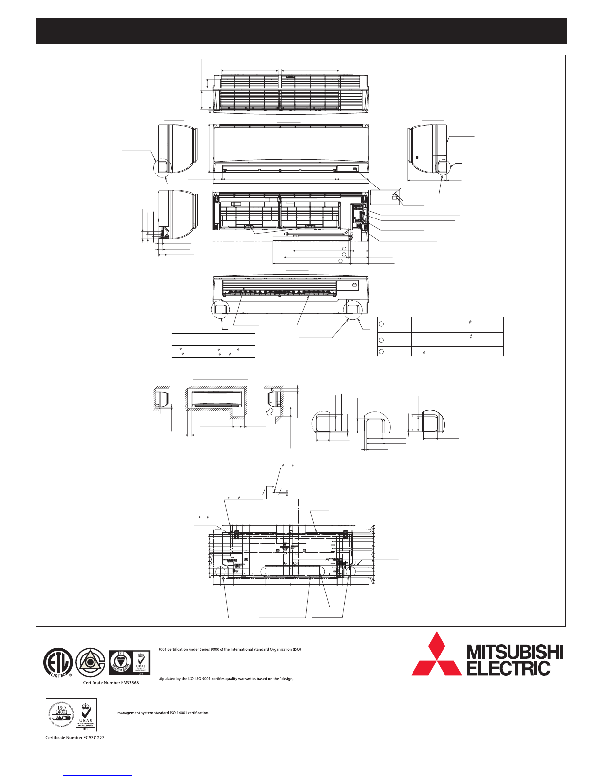
External Dimensions
Inches………………………..14-3/8 H x 46 -1/16 W x 11-5/8 D
mm…………………………………….365 H x 1,170 W x 295 D
Notes:
R1-15/32(R37.5)
Knock out hole
for left piping
Model: PKFY-P24NKMU-E2 – DIMENSIONS
Top side
17(431.7)16-11/16(423.7)
2-9/16(65.2)
5-17/132(140.3)
7/16(11)
1-1/4(32)
2-3/32(53)
23/32(18)
Left side
A
2-19/32(66)
1-3/16(30)
1-3/8(35)
14-3/8(365)
Filter hook
33-21/32(855)2-29/32(74)
Front side(Grille open)
Front side
46-1/16(1170)
17-15/32(444)Gas pipe
18-31/32(482)Liquid pipe
23-1/32(585)Drain hose
Under side
9-1/2(241)
2
1
3
Terminal block for power supply
Terminal block for transmission
Terminal block for
MA-remote controller
Emergency operation switch
(cooling/heating)
4-27/32(123)
6-1/16(154)
5-9/32(134)
Right side
11-5/8(295)
Operation lamp
DEFROST/STAND BY lamp
Receiver
Mount board
3/16(5)
Knock out hole
for right piping
Unit : in(mm)
C
Sleeve
(purchased locally)
2-15/16
( 75)
Min.9/32(7)
1-31/32(50)
2-15/16(75)
3-15/16(100)
4-19/32(117)
4-29/32(125)
5-19/32(142)
7-9/16(192)
9-17/32(242)
11-1/2(292)
Through hole
2-15/16~ 3-5/32
( 75~ 80)
Required space(Indoor unit)
Min.2-27/32(72.4)
75- 3/16( 5.1)
Tapping
20-3/8(517.4)
screw hole
5/8(15.5)
0
31/32(25)
11(279.5)
23-1/32(585)
20-7/8(530.5)
Vane(auto)
(inch)
Min.2(50.5)Min.8-21/32(220)
4- 11/32( 9) Bolt hole
17-7/8(454)
16-3/32(408.5)
15-1/8(384)
14-11/32(364)
17-9/32(439)
15-1/8(384)
16-15/16(430.5)
Wall hole for
left rear piping
Air inlet
Air outlet
12-3/8(314)
13-11/32(339)
Center measurement hole
3/32( 2.5)
2-1/8(54)
0
1/8(3)
4-11/32(110)
2-3/8(60)
13/32(10)
0
0
7-7/16(189)
Knock out hole for
left rear piping
2-15/16×18-29/32(75×480)
Louver(manual)
Knock out hole
for lower piping
Min.1-7/8(48)
Min.9-27/32(250)
2-3/8(60)
4-11/32(110)
13/32(10)
Mount board
Wall hole for
right rear piping
C
2-9/16(65)
12-3/8(314)
8-17/32(216.5)
2-5/8(67)
3-1/32(77)
15-1/8(384.5)
14-11/32(364)
13-11/32(339)
13-3/4(349.2)
5/16(7.8)
18-5/16(465.5)
17-7/8(454)
16-3/32(408.5)
17-9/32(439)
15-1/8(384)
17-11/16(449.2)
2-9/16(65)
Piping connection department
1 Liquid pipe
BB
2 Gas pipe
3 Drain hose
Knock out hole for piping
B
3-1/32(77)
3-7/16(87)
13/32(10.7)
Indoor unit outline
2-1/8(54)
1-1/4(32)
31/32(25)
1/2(12.5)
0
1/2(12.5)
1-15/32(37.5)
2-15/32(62.5)
3-7/16(87.5)
4-1/8(104.5)
5-3/32(129.5)
6-9/16(167)
8-17/32(217)
9-1/32(229.5)
10-13/32(264)
11-1/2(292)
12-5/32(308.5)
12-1/4(311)
23-1/32(585)
Refrigerant pipe: 3/8 O.D( 9.52)
Flared connection: 3/8F
Refrigerant pipe: 5/8 O.D( 15.88)
Flared connection: 5/8F
5/8( 16) I.D
A
3-1/32(77)
2-5/8(67)
5/16(7.8)
2-9/16(65)
Mitsubishi Electric Air Conditioning & Refrigeration Systems Works acquired ISO
based on a review of quality warranties for the production of refrigeration and air
conditioning equipment.
ISO Authorization System
The ISO 9000 series is a plant authorization system relating to quality warranties as
development, production, installation and auxiliary services" for products built at
an authorized plant.
Mitsubishi Electric Air Conditioning & Refrigeration Systems Works acquired environmental
The ISO 14000 series is a set of standards applying to environmental protection set by the
International Standard Organization (ISO).
Mitsubishi Electric Sales Canada Inc.
www.MitsubishiElectric.ca
Specifications are subject to change without notice.
SB_PKFY-P24NKMU-E2_201205
 Loading...