

Page 1
Air-Conditioners For Building Application
INDOOR UNIT
PKFY-P·VBM-E
INSTALLATION MANUAL
For safe and correct use, please read this installation manual thoroughly before installing the air-conditioner
unit.
INSTALLATIONSHANDBUCH
Zum sicheren und ordnungsgemäßen Gebrauch der Klimaanlage das Installationshandbuch gründlich durchlesen.
MANUEL D’INSTALLATION
Veuillez lire le manuel d’installation en entier avant d’installer ce climatiseur pour éviter tout accident et vous assurer d’une utilisation correcte.
INSTALLATIEHANDLEIDING
Voor een veilig en juist gebruik moet u deze installatiehandleiding grondig doorlezen voordat u de airconditioner
installeert.
MANUAL DE INSTALACIÓN
Para un uso seguro y correcto, lea detalladamente este manual de instalación antes de montar la unidad de
aire acondicionado.
MANUALE DI INSTALLAZIONE
Per un uso sicuro e corretto, leggere attentamente questo manuale di installazione prima di installare il condizionatore d’aria.
ΕΓΧΕΙΡΙΔΙΟ ΟΔΗΓΙΩΝ ΕΓΚΑΤΑΣΤΑΣΗΣ
Για ασφάλεια και σωστή χρήση, лαρακαλείστε διαβάσετε пρоσεχτικά αυτό το εγχειρίδιο εγκατάστασης пριν
αρχίσετε την εγκατάσταση της μονάδας κλιματισμού.
MANUAL DE INSTALAÇÃO
Para segurança e utilização correctas, leia atentamente este manual de instalação antes de instalar a unidade
de ar condicionado.
MONTAJ ELKİTABI
Emniyetli ve doğru biçimde nasıl kullanılacağını öğrenmek için lütfen klima cihazını monte etmeden önce bu
elkitabını dikkatle okuyunuz.
РУКОВОДСТВО ПО УСТАНОВКЕ
Для осторожного и правильного использования прибора необходимо тщательно ознакомиться с данным
руководством по установке до выполнения установки кондиционера.
FOR INSTALLER
FÜR INSTALLATEURE
POUR L’INSTALLATEUR
VOOR DE INSTALLATEUR
PARA EL INSTALADOR
PER L’INSTALLATORE
ΓΙΑ ΑΥΤΟΝ ΠΟΥ ΚΑΝΕΙ ΤΗΝ ΕΓΚΑΤΑΣΤΑΣΗ
PARA O INSTALADOR
MONTÖR İÇİN
ДЛЯ УСТАНОВИТЕЛЯ
English (GB)
Deutsch (D)
Français (F)
Nederlands (NL)
Español (E)
Italiano (I)
Ελληνικά (GR)
Português (P)
Türkçe (TR)
Русский (RU)
Page 2
Contents
1. Safety precautions .....................................................................................2
2. Installation location .................................................................................... 2
3. Installing the indoor unit ............................................................................3
4. Refrigerant pipe and drain pipe .................................................................4
5. Electrical work ...........................................................................................6
6. Test run ......................................................................................................7
Note:
The phrase “Wired remote controller” in this installation manual refers only to the PAR-21MAA.
If you need any information for the other remote controller, please refer to either the installation manual or initial setting manual which are
included in these boxes.
1. Safety precautions
Before installing the unit, make sure you read all the “Safety precautions”.
Please report to your supply authority or obtain their consent before
connecting this equipment to the power supply system.
Warning:
Describes precautions that must be observed to prevent danger of injury or
death to the user.
Caution:
Describes precautions that must be observed to prevent damage to the unit.
After installation work has been completed, explain the “Safety Precautions,” use,
and maintenance of the unit to the customer according to the information in the
Operation Manual and perform the test run to ensure normal operation. Both the
Installation Manual and Operation Manual must be given to the user for keeping.
These manuals must be passed on to subsequent users.
Warning:
• Ask the dealer or an authorized technician to install the air conditioner.
• Install the unit at a place that can withstand its weight.
• Use only specified cables for wiring. The wiring connections must be made
securely with no tension applied on the terminal connections. Also, never
splice the cables for wiring (unless otherwise indicated in this document).
GB
Failure to observe these instructions may result in overheating or a fire.
• Use only accessories authorized by Mitsubishi Electric and ask the dealer
or an authorized technician to install them.
• Do not touch the heat exchanger fins.
• Install the air conditioner according to this Installation Manual.
• Have all electric work done by a licensed electrician according to local
regulations.
Caution:
Do not use the existing refrigerant piping, when use R410A or R407C refrigerant.
•
• Use ester oil, either oil or alkylbenzene (small amount) as the refrigerator oil
to coat flares and flange connections, when use R410A or R407C refrigerant.
• Do not use the air conditioner where food, pets, plants, precision instru-
ments, or artwork are kept.
• Do not use the air conditioner in special environments.
• Ground the unit.
: Indicates an action that must be avoided.
: Indicates an important instructions that must be followed.
: Indicates a part which must be grounded.
: Indicates that caution should be taken with rotating parts.
: Indicates that the main switch must be turned off before servicing.
: Beware of electric shock.
: Beware of hot surface.
: At servicing, please shut down the power supply for both the Indoor and
ELV
Outdoor Unit.
Warning:
Carefully read the labels affixed to the main unit.
• If the air conditioner is installed in a small room, measures must be taken
to prevent the refrigerant concentration from exceeding the safety limit
even if the refrigerant should leak.
• The cut face punched parts may cause injury by cut, etc. The installers are
requested to wear protective equipement such as gloves, etc.
• When installing or relocating, or servicing the air conditioner, use only the
specified refrigerant (R410A) to charge the refrigerant lines. Do not mix it
with any other refrigerant and do not allow air to remain in the lines.
If air is mixed with the refrigerant, then it can be the cause of abnormal high pressure
in the refrigerant line, and may result in an explosion and other hazards.
The use of any refrigerant other than that specified for the system will cause
mechanical failure or system malfunction or unit breakdown. In the worst
case, this could lead to a serious impediment to securing product safety.
• Install an leak circuit breaker, as required.
• Use power line cables of sufficient current carrying capacity and rating.
• Use only a circuit breaker and fuse of the specified capacity.
• Do not touch the switches with wet fingers.
• Do not touch the refrigerant pipes during and immediately after operation.
• Do not operate the air conditioner with the panels and guards removed.
• Do not turn off the power immediately after stopping operation.
2. Installation location
D
H
W
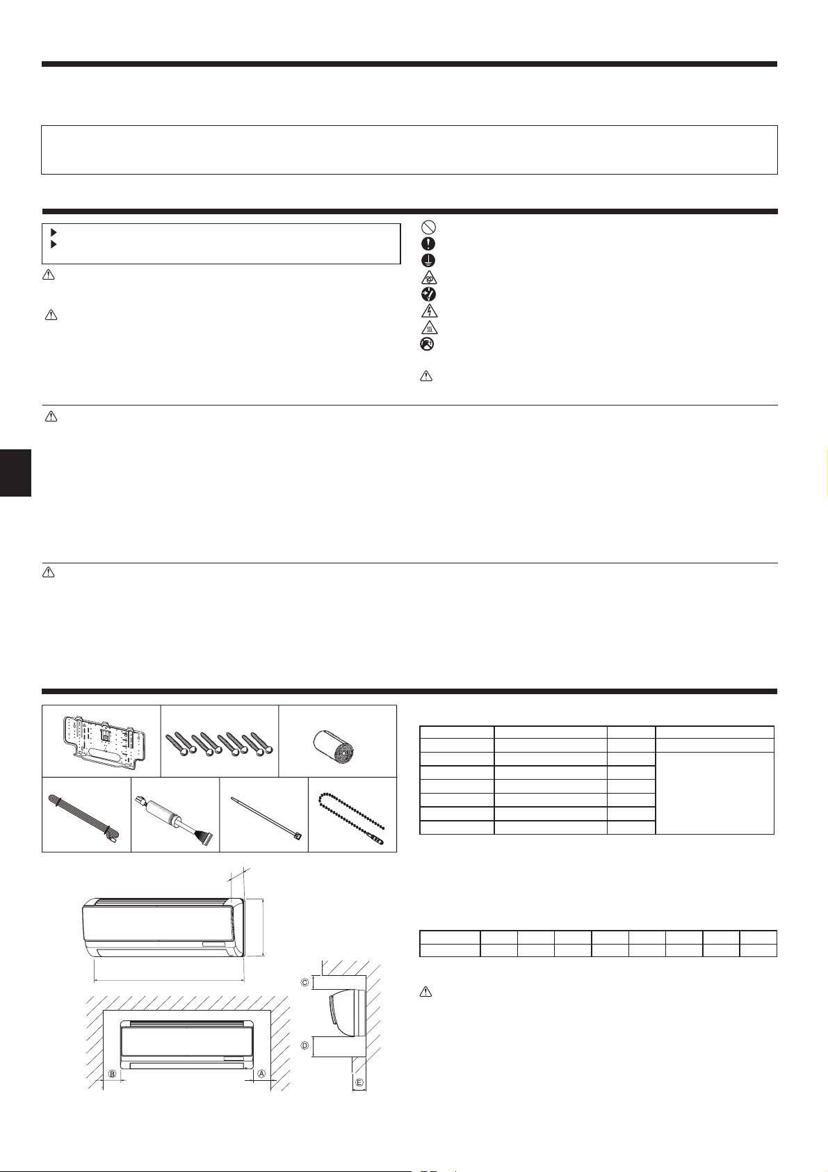
The indoor unit comes with the following parts and accessories:
PART NUMBER ACCESSORY
1
2
3
4
5
6
7
Wall-fixing bracket 1
Tapping screw 4 × 25 8
Felt tape 1
MA remote controller cable
Cable 1
Band 1
Fastener 1
QUANTITY
1
LOCATION OF SETTING
Fix at the back of the unit
Set in packing material
2.1. Outline dimensions (Indoor unit) (Fig. 2-1)
Select a proper position allowing the following clearances for installation and maintenance.
Models W D H
PKFY-P·VBM 815 225 295 Min. 20 Min. 22 Min. 50
*1 : 60mm or more for left and left back piping.
Warning:
Mount the indoor unit on a wall strong enough to withstand the weight of the
unit.
ABC*1DE
Min. 100
(mm)
Max. 90
Fig. 2-1
2
Page 3
3. Installing the indoor unit
79.5
79.5 328
190
450
450
100
Fig. 3-1
260
109.5
(mm)
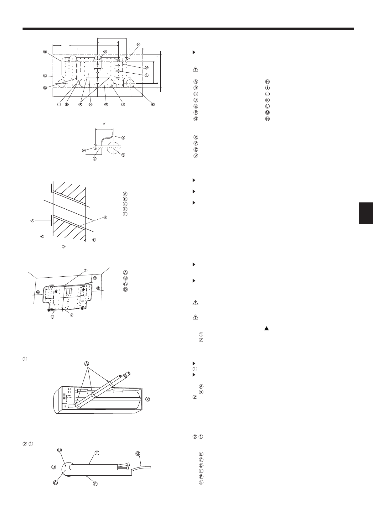
3.1. Installing the wall mounting fixture (Fig. 3-1)
3.1.1. Setting the wall mounting fixture and piping positions
Using the wall mounting fixture, determine the unit’s installation position
and the locations of the piping holes to be drilled.
196.5
245.5
283 9
Warning:
Before drilling a hole in the wall, you must consult the building contractor.
Supporting piece Knockout hole (12-ø2.6)
3
298
109.5
40.5
Mount board Knockout hole (4-ø9)
Main body Knockout hole (87-ø5.4)
Slot (4-4.5 × 35) Piping hole (ø65)
Knockout hole (8-ø4.3) Slot (4-4.5 × 40)
Level setting standard Slot (4-4.5 × 37)
Knockout hole Slot (4-11 × 20)
W: Location for wall holes
Wall mounting fixture
105
Hole centre
Align the scale with the line.
Insert scale.
3.1.2. Drilling the piping hole (Fig. 3-2)
Use a core drill to make a hole of 90-100 mm diameter in the wall in the
piping direction, at the position shown in the diagram to the left.
Sleeve
Hole
(Indoors)
Wall
(Outdoors)
The hole should incline so that the outside opening is lower than the in-
side opening.
Insert a sleeve (with a 90 mm diameter and purchased locally) through the
hole.
Note:
The purpose of the hole’s inclination is to promote drain flow.
GB
Fig. 3-2
3.1.3. Installing the wall mounting fixture
Since the indoor unit weighs near 10 kg, selection of the mounting loca-
Min. 100 mm
Min. 130 mm
Min. 59 mm
Mount board
450
*1: 69mm or more for left and
left back piping
*1
Fig. 3-3
tion requires thorough consideration. If the wall does not seem to be
strong enough, reinforce it with boards or beams before installation.
The mounting fixture must be secured at both ends and at the centre, if
possible. Never fix it at a single spot or in any unsymetrical way.
(If possible, secure the fixture at all the positions marked with a bold ar-
row.) (Fig. 3-3)
Warning:
If possible, secure the fixture at all positions indicated with a bold arrow.
Caution:
• The unit body must be mounted horizontally.
• Fasten at the holes marked with
Fasten a thread to the hole.
The level can be easily obtained by hanging a weight from the string and aligning the
string with the mark.
as shown by the arrows.
3.2. Preparation for piping connection
Remove the vinyl band that holds the drain pipe.
Rear, right and lower piping (Fig. 3-4)
Bind the refrigerant pipes and drain pipe with vinyl tape at three or more
points. This will facilitate passing the pipes through the wall.
Vinyl tape
This figure is viewed from the back of the unit.
Left and left rear piping
Fig. 3-4
- For left rear piping, pull the pipes out the hole to determine their correct
-
length, then bend them. The indoor unit should hang on the wall mounting
fixture. (Fig. 3-5)
Wall
Wall hole
Bent section
Refrigerant pipe
Drain pipe
Transmission cable
Fig. 3-5
3
Page 4
3. Installing the indoor unit
8
GB
-
Fig. 3-6 Fig. 3-7
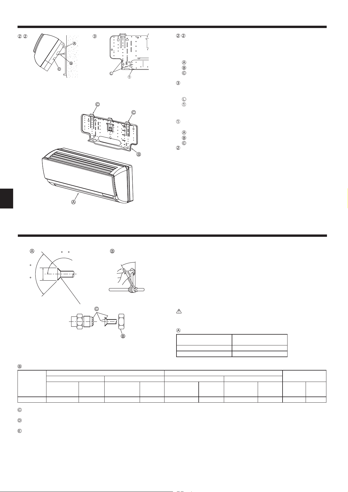
- Lift the indoor unit by hooking the supporting piece (attached to the mount
board) to the ribs on the back of the unit as shown. (Fig. 3-6)
When piping work etc. is complete, replace the supporting piece on the
mount board.
(If the unit is not fixed securely, vibration may occur during operation.)
Mount board
Supporting piece
Rib
If the flare pipe is to be embedded into the wall in advance: (Fig. 3-7)
• Determine the length of pipe to be embedded by marking on the mounting plate
as a reference.
Mark
Wall mounting fixture
3.3. Mounting the unit (Fig. 3-8)
Securely place the hanging fixtures for the indoor unit over the catches on the
wall mounting fixture.
Indoor unit
Wall mounting fixture
Catch
When piping has been completed, install the indoor unit and wall mounting fix-
ture with fixing screws.
Fig. 3-8
4. Refrigerant pipe and drain pipe
45 ±2
øA
90 ±0.5
R0.4 - R0.
Fig. 4-1
Refrigerant pipe sizes & Flare nut tightening torque
R407C or R22 R410A
Liquid pipe Gas pipe Liquid pipe Gas pipe
Pipe size(mm)
P15/P20/25 ODø6.35 (1/4”) 14 - 18 ODø12.7 (1/2”) 49 - 61 ODø6.35 (1/4”) 14 - 18 ODø12.7 (1/2”) 49 - 61 17 26
Tighten-
ing torque
(N.m)
Pipe size (mm)
Tightening
torque
(N.m)
4.1. Connecting pipes (Fig. 4-1)
• When commercially available copper pipes are used, wrap liquid and gas pipes
with commercially available insulation materials (heat-resistant to 100 °C or more,
thickness of 12 mm or more).
• The indoor parts of the drain pipe should be wrapped with polyethylene foam in-
sulation materials (specific gravity of 0.03, thickness of 9 mm or more).
• Apply thin layer of refrigerant oil to pipe and joint seating surface before tighten-
ing flare nut.
• Use two wrenches to tighten piping connections.
• Use refrigerant piping insulation provided to insulate indoor unit connections. In-
sulate carefully.
Warning:
When installing the unit, securely connect the refrigerant pipes before starting the compressor.
Flare cutting dimensions
Copper pipe O.D.
Pipe size (mm)
(mm)
ø6.35 8.7 - 9.1
ø12.7 16.2 - 16.6
Tightening
torque
(N.m)
Pipe size (mm)
Flare dimensions
øA dimensions (mm)
Tightening
torque
(N.m)
Flare nut O.D.
Liquid pipe
(mm)
Gas pipe
(mm)
Do not apply refrigerating machine oil to the screw portions.
(This will make the flare nuts more apt to loosen.)
Be certain to use the flare nuts that are attached to the main unit.
(Use of commercially-available products may result in cracking.)
Apply refrigerating machine oil over the entire flare seat surface.
4
Page 5
4. Refrigerant pipe and drain pipe
(mm)
110
450
520 116
Fig. 4-2
(mm)
54
24.4
10
45
10
50
16
2.5
91.5
45
16
50
4
2.5
10
34
Fig. 4-3
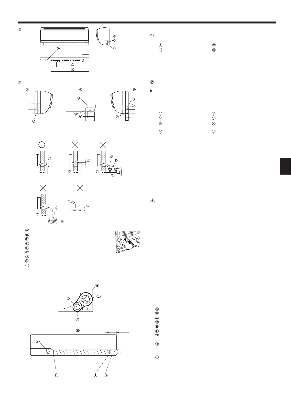
4.2. Positioning refrigerant and drain piping
Position of refrigerant and drain piping (Fig. 4-2)
• The drain pipe can be cut midway to meet the on-site conditions.
(Effective length: 640) Gas pipe
Liquid pipe Drain hose
Determine the position of the knockout holes on the unit body. (Fig. 4-3)
Cut the knockout holes using a saw blade or an adequate knife.
Take care not to damage other parts of the unit.
• Remove the corner box and drill a knockout hole. If a hole is made without removing the box, the drain hose could be damaged.
Left-side piping Corner box
Lower piping Knockout hole for lower piping
Right-side piping Through hole for the remote controller’s
Knockout hole for left-side piping Knockout hole for right-side piping
cable
4.3. Drain piping (Fig. 4-4)
• Drain pipes should have an inclination of 1/100 or more.
• For extension of the drain pipe, use a soft hose (inner dia. 16 mm) available on
the market or hard vinyl chloride pipe (VP-16). Make sure that there is no water
leakage from the connections.
• If the drain pipe passes indoors it must be covered with insulating material (foamed
polyethylene: specific gravity: 0.03, thickness: 9 mm or more) available on the
market.
• Do not put the drain piping directly in a drainage ditch where sulphuric gas may
be generated.
• When piping has been completed, check that water flows from the end of the
drain pipe.
Caution:
The drain pipe should be installed according to this Installation Manual to
ensure correct drainage. Thermal insulation of the drain pipes is necessary
to prevent condensation. If the drain pipes are not properly installed and insulated, condensation may drip on the ceiling, floor or other possessions.
GB
Inclined downwards
Must be lower than outlet point
Water leakage
Trapped drainage
Air
Wavy
The end of drain pipe is under water.
Drainage ditch
5 cm or less between the end of drain pipe and
the ground
Fig. 4-4
100
(mm)
4.4. Completing the piping (Fig. 4-5)
• To prevent condensation from dripping, put felt tape over the insulation materials
on the refrigerant and drain pipes within the unit as shown in the diagram.
• Arrange the drain hose so that it goes to the bottom of the unit.
• The overlapping width of felt tape is one half of the tape width.
Felt tape
Liquid pipe
Gas pipe
Drain piping
Viewed from the back
Take care that the middle of the drain hose is not raised.
In the case of left piping, the refrigerant pipes and the drain pipe should be taped
separately.
Wrap together the refrigerant pipes and the drain pipe with felt tape so that white felt over
laps by 20 mm or more.
* The pipes should be wrapped so that they are housed behind the unit.
Fix the end of the felt tape with a bandage fixture.
Fig. 4-5
5
Page 6

5. Electrical work
GB
CN90
Right side view (from /)
Claw
Clamp
/
NL
M1
M2
Fasten the cables with the clamp
Cable(Front panel side)
Terminal block for power supply
A
Terminal block for transmission cable (Shared with the M-NET remote controller)
B
Connector for MA remote controller
C
MA remote controller cable (ACCESSORY 4)
D
Cable (ACCESSORY 5)
E
Band (ACCESSORY 6)
F
The clamp for on-site wiring
G
Fig. 5-1
Connect the connector
5.1. Indoor unit (Fig. 5-1,5-2)
1) Remove the front panel, then remove the corner box from the lower right corner
of the indoor unit.
2) Remove the screw fixing the electric parts cover and remove the cover.
3) Connect the power cable and transmission cable to the terminal block.
• The electric parts box may have to be pulled forward during customer service
etc. Therefore, the wires must have some extra length.
4) Connect the connector for MA remote controller. (Non-polarized 2-wire)
5) Connect the attached cable 5 to the CN90 on controller board in the electrical
parts box.
* Be sure to connect in case of using MA/M-NET Remote controller.
6) Fix the MA Remote controller cable 4 and the cable 5 with the clamp through
the claw on the right side of the electrical parts box.
7) Fix the MA remote controller cable 4 on the fixing clamp with the cable running
along the down side of the terminal block.
8) Fix the cable 5 with the attached band 6.
9)
Bring out the lead wire on the back side of the front panel to the corner box side.
Put back the electrical cover and front panel. (Do not pull the lead wire strongly.)
10) After connecting the connectors (yellow 9-pole) on the indoor unit and front
panel, slide the glass tube and fix it with the attached fastener 7 at which the
connector joint part is not exposed.
* Be sure to connect in case of using MA/M-NET Remote controller.
11) Fix each wire with the clamp for on-site wiring under the electrical parts box and
put the corner box cover back.
A means for the disconnection of the supply with an isolation switch, or similar device, in all active conductors shall be incorporated in the fixed wiring.
5.2. Power supply wiring
• Wiring size must comply with the applicable local and national code.
• Power supply codes of appliance shall not be lighter than design 245 IEC 53 or
227 IEC 53.
• Install an earth line longer than other cables.
• A switch with at least 3 mm, 1/8 inch contact separation in each pole shall be pro-
vided by the air conditioner installation.
Power cable size : more than 1.5mm
2
(3-core)
Direction to slide
ABE
LN
C
TB2 TB5 TB15
M1 M2
Fig. 5-2
12
Fig. 5-3
Fastener
(Leave about four beads
and cut the rest. )
Switch 16 A
A
Overcurrent protection 16 A
B
Indoor unit
C
Total operating current be less than 16 A
D
Pull box
E
Warning:
Never splice the power cable or the indoor-outdoor connection cable, otherwise it may result in a smoke, a fire or communication failure.
Selecting non-fuse breaker (NF) or earth leakage breaker (NV).
For breaker, means shall be provided to ensure disconnection of all active
phase conductors of the supply.
5.3. Types of control cables
1. Wiring transmission cables
Types of transmission cable Shielding wire CVVS or CPEVS
Cable diameter More than 1.25 mm
2
Length Less than 200m
2. M-NET Remote control cables
Types of remote control cable
Cable diameter More than 0.5 to 1.25 mm
Length
Shielding wire MVVS
2
Add any portion in excess of 10m to within the
longest allowable transmission cable length 200m.
3. MA Remote control cables
Types of remote control cable
Cable diameter 0.3 to 1.25 mm
2-core cable (unshielded)
2
Length Less than 200m
5.4. Connecting remote controller, indoor and outdoor
transmission cables (Fig. 5-4)
• Connect indoor unit TB5 and outdoor unit TB3. (Non-polarized 2-wire) The “S” on
indoor unit TB5 is a shielding wire connection. For specifications about the connecting cables, refer to the outdoor unit installation manual.
Note:
As for PKFY-P·BM series, TB5 has two terminals and does not have S terminal.
The earths of shielding wires are crimping-connected. Insulate the connected
parts with insulating tapes and so on.
•
Install a remote controller following the manual supplied with the remote controller.
• Connect the remote controller’s transmission cable within 10 m using a 0.75 mm2
core cable. If the distance is more than 10 m, use a 1.25 mm
2
junction cable.
6
Page 7

5. Electrical work
M1M2 M1M2M1M2
TB3 TB5 TB5
TB3
TB3
M1M2
M1M2
ON
OFF
M1M2
TB5
Pair No.
0
Pair No.
0
SW5
220V 240V
12345678910
0
1
9
8
7
6
5
S S
S S
M1M2
TB5
SM1 M2 SM1 M2
TB5
21 21
Fig. 5-4
SW1
SW11SW12
0
1
9
2
3
4
2
8
3
7
4
6
5
Fig. 5-5
2121
a
Pair No.
0
TB5
CN43
CN82
SW14
0
1
F
2
E
3
D
4
C
5
B
6
A
7
9
8
ಽጘญ0Qࡍࠕ0Q
㧔$4#0%*0Q㧔U&+)+6㧔VJU&+)+6
MA Remote controller
1
• Connect the “1” and “2” on indoor unit TB15 to a MA remote controller. (Nonpolarized 2-wire)
• DC 9 to 13 V between 1 and 2 (MA remote controller)
M-NET Remote controller
2
• Connect the “M1” and “M2” on indoor unit TB5 to a M-NET remote controller.
(Nonpolarized 2-wire)
• DC 24 to 30 V between M1 and M2 (M-NET remote controller)
Wireless remote controller(When installing wireless signal receiver)
3
• Connect the wire of wireless signal receiver (9-pole cable) to CN90 of indoor controller board.
• When more than two units are run under group control using wireless remote
controller, connect TB15 each with the same number.
• To change Pair No. setting, refer to installation manual attached to wireless remote controller. (In the default setting of indoor unit and wireless remote controller, Pair No. is 0.)
Terminal block for indoor transmission cable
Terminal block for outdoor transmission cable(M1(A), M2(B), (S))
Remote controller Wireless signal receiver Wireless remote controller
5.5. Setting addresses (Fig. 5-5)
(Be sure to operate with the main power turned OFF.)
• There are two types of rotary switch setting available: setting addresses 1 to 9
and over 10, and setting branch numbers.
How to set addresses
Example: If Address is “3”, remain SW12 (for over 10) at “0”, and match SW11
(for 1 to 9) with “3”.
How to set branch numbers SW14 (Series R2 only)
Match the indoor unit’s refrigerant pipe with the BC controller’s end connec-
tion number.
Remain other than series R2 at “0”.
• The rotary switches are all set to “0” when shipped from the factory. These
switches can be used to set unit addresses and branch numbers at will.
• The determination of indoor unit addresses varies with the system at site. Set
them referring to the Data Book.
5.6. Sensing room temperature with the built-in sen-
sor in a remote controller
If you want to sense room temperature with the built-in sensor in a remote controller, set SW1-1 on the control board to “ON”. The setting of SW1-7 and SW1-8 as
necessary also makes it possible to adjust the air flow at a time when the heating
thermometer is OFF.
GB
6. Test run
6.1. Before test run
After completing installation and the wiring and piping of the indoor and
outdoor units, check for refrigerant leakage, looseness in the power supply or control wiring, wrong polarity, and no disconnection of one phase
in the supply.
Use a 500-volt megohmmeter to check that the resistance between the
power supply terminals and ground is at least 1.0 M
TEST RUN
COOL, HEAT
MENU
MONITOR/SET
BACK DAY
PAR-21MAA
TEMP.
CLOCK
°C
°C
ON/OFF
OPERATION
SIMPLE
ON/OFF
FILTER
CHECK
CLEAR
TEST
Fig. 6-1
.
ON/OFF button
Test run display
Liquid pipe (Indoor unit)
temperature display
ON/OFF lamp
Power display
Error code display
Test run remaining time display
Set temperature button
Mode selection button
Air direction button
TEST button
Fan Speed button
Louver button
Do not carry out this test on the control wiring (low voltage circuit) termi-
nals.
Warning:
Do not use the air conditioner if the insulation resistance is less than 1.0 M
6.2. Test run
Using wired remote controller (Fig. 6-1)
Turn on the power at least 12 hours before the test run.
Press the [TEST] button twice. “TEST RUN” liquid crystal display
Press the [Mode selection] button and switch to the cooling (or heating) mode.
Make sure that cold (or warm) wind is blown out.
Press the [Fan speed] button. Make sure that the wind speed is switched.
Press the [Air direction button] or [Louver button].
Check operation of the vane or louver.
Check operation of the outdoor unit fan.
Release test run by pressing the [ON/OFF] button. Stop
Register a telephone number.
The telephone number of the repair shop, sales office, etc., to contact if an error
occurs can be registered in the remote controller. The telephone number will be
displayed when an error occurs. For registration procedures, refer to the operation manual for the indoor unit.
Note:
• If an error code is displayed on the remote controller or if the air conditioner does not operate properly, refer to the outdoor unit installation manual
or other technical materials.
• The OFF timer is set for the test run to automatically stop after 2 hours.
• During the test run, the time remaining is shown in the time display.
• During the test run, the temperature of the indoor unit refrigerant pipes is
shown in the room temperature display of the remote controller.
• When the VANE or LOUVER button is pressed, the message “NOT AVAILABLE” may appear on the remote controller display depending on the indoor
unit model, but this is not a malfunction.
7
.
Page 8

Содержание
1. Меры предосторожности.......................................................................56
2. Место установки .................................................................................... 56
3. Установка внутреннего прибора ...........................................................57
Примечание:
В этом руководстве по использованию аппарата фраза “проводной пульт дистанционного управления” относится к пульту дистанционного управления PAR-21MAA.
Сведения о других пультах дистанционного управления приводятся в руководстве по установке или руководстве по начальным настройкам, находящемся в этих коробках.
4. Труба хладагента и дренажная труба ..................................................58
5. Электрические работы .......................................................................... 60
6. Выполнение испытания.........................................................................61
1. Меры предосторожности
До установки прибора убедитесь, что Вы прочли все “Меры предосторожности”.
Пожалуйста, перед подключением данного оборудования к сис-
теме электропитания, сообщите об этом своему поставщику электропитания или получите его разрешение.
Предупреждение:
Описывает меры предосторожности, необходимые для предотвращения
получения травмы или гибели пользователя.
Осторожно:
Описывает меры предосторожности, необходимые для предотвращения
повреждения прибора.
После окончания установочных работ проинструктируйте пользователя относительно
правил эксплуатации и обслуживания аппарата, а также ознакомьте с разделом “Меры
предосторожности” в соответствии с информацией, приведенной в Руководстве по
использованию аппарата, и выполните тестовый прогон аппарата для того, чтобы
убедиться, что он работает нормально. Обязательно передайте пользователю на
хранение экземпляры Руководства по установке
Руководства должны быть переданы и последующим пользователям данного прибора.
Предупреждение:
• Обратитесь к дилеру или квалифицированному технику для выполне-
ния установки кондиционера воздуха.
• Устанавливайте прибор в месте, способном выдержать его вес.
• Используйте для проводки указанные кабели. Убедитесь, что кабели надеж-
но соединены, а оконечные соединения не натянуты. Никогда не соединяйте кабели внахлест (если иное не указано в прилагаемой документации). Несоблюдение этих инструкций может привести к перегреву или возгоранию.
• Используйте только те дополнительные принадлежности, на которые
имеется разрешение от Mitsubishi Electric; для их установки обращайтесь к дилеру или уполномоченному специалисту по установке.
• Не прикасайтесь к лопастям теплообменника.
• Устанавливайте кондиционер согласно инструкциям, приведенным в
данном Руководстве по установке.
Все электроработы должны выполняться квалифицированным электриком, име-
•
ющим соответствующую лицензию, в соответствии с местными нормативами.
Осторожно:
• При использовании хладагента R410A или R407C следует заменить ус-
тановленные ранее трубы хладагента.
•
Используйте эфирное масло или алкилбензин (в небольших количествах) в
качестве охлаждающего масла для смазывания раструбных и фланцевых
трубных соединений при использовании хладагента R410A или R407C.
•
Не используйте кондиционер воздуха в местах содержания продуктов, домашних животных, растений, точных приборов или предметов искусства.
• Не используйте кондиционер воздуха в особых условиях.
и Руководства по эксплуатации. Эти
: Указывает действие, которое следует избегать.
: Указывает на важную инструкцию.
: Указывает, что данная часть должна быть заземлена.
: Ук азывает на необходимость проявлять осторожность по отношению к
вращающимся частям.
: Указывает на необходимость отключения главного выключателя перед
проведением техобслуживания.
: Опасайтесь электрошока.
: Опасайтесь горячих поверхностей.
: При проведении техобслуживания отключите электропитание как
ELV
внутреннего, так и наружного прибора.
Предупреждение:
Внимательно прочтите текст на этикетках главного прибора.
• Если кондиционер установлен в небольшом помещении, необходимо
принять меры для предотвращения концентрации хладагента свыше
безопасных пределов в случае утечки хладагента.
Вырубленные грани отпресованных деталей могут нанести травмы - порезы и
•
т.д. Просим установщиков надевать защитную одежду, например, перчатки и т.д.
•
При установке, перемещении или сервисном обслуживании кондиционера используйте только указанный хладагент (R410A) для заправки
трубопроводов хладагента. Не допускается его смешивание с другим
хладагентом или наличие воздуха в трубопроводах.
При смешивании воздуха с хладагентом может произойти чрезмерное
повышение давления в трубопроводе хладагента, что способно вызывать взрыв или другие нештатные ситуации.
Использование любого иного хладагента, кроме указанного для системы, при-ведет к механическому отказу, неисправности системы или
поломке прибора. В худшем случае это может привести к серьезному
препятствию для
• Заземлите прибор.
• Установите прерыватель цепи, если требуется.
• Используйте сетевой кабель достаточной мощности напряжения.
• Используйте прерыватель цепи и предохранитель указанной мощности.
• Не прикасайтесь к выключателям мокрыми руками.
• Не прикасайтесь к трубам хладагента во время работы и сразу после
выключения прибора.
используйте кондиционер воздуха, если его панели и крышки сняты.
• Не
• Не отключайте питание немедленно после выключения прибора.
обеспечения безопасности изделия.
2. Место установки
D
RU
56
W
Fig. 2-1
H
Внутренний прибор поставляется со следующими частями и приспособлениями:
НОМЕР ЧАСТИ ПРИСПОСОБЛЕНИЕ
1
2
3
4
5
6
7
2.1.
Наружные размеры прибора (Внутренний прибор) (Fig. 2-1)
Выберите такое место для установки, которое обеспечивало бы следующие
зазоры, необходимые для установки и техобслуживания.
Модель WDH
PKFY-P·VBM 815 225 295 Min. 20 Min. 22 Min. 50
*1 : 60 мм или более для левой и левой задней трубной обвязки.
Предупреждение:
Установите внутренний прибор на достаточно прочной стене, которая
способна выдерживать его вес.
Кронштейн для за-
крепления на стене
Самонарезающий
винт 4 × 25
Войлочная лента 1
Кабель пульта дистанционного
управления МА
Кабель 1
Поясок 1
Зажим 1
КОЛИЧЕСТВО
ABC*1DE
РАСПОЛОЖЕНИЕ ПРИ
УСТАНОВКЕ
1
8
1
Укрепить на задней
панели прибора
В упаковочном матери-
але
Min. 100
(мм)
Max. 90
Page 9

3. Установка внутреннего прибора
79.5
79.5 328
190
450
450
100
Fig. 3-1
260
109.5
(мм)
3.1. Установка настенного крепления (Fig. 3-1)
3.1.1. Установка настенного крепления и позиции труб
Используя настенное крепление, определите положение установки при-
бора и будущее расположение просверленных отверстий для труб.
196.5
245.5
283 9
Предупреждение:
Перед сверлением отверстия в стене необходимо получить консультацию у подрядчика-строителя.
A
3
298
105
109.5
40.5
Поддерживающая часть
B
Монтажный щит
C
Корпус
D
Щель (4-4,5 × 35)
E
Пробиваемое отверстие (8-ø4,3)L Щель (4-4,5 × 40)
F
Эталон ровной установки
G
Пробиваемое отверстие
Расположение отверстий в стене
W:
X
Настенный кронштейн
Y
Центр отверстия
Z
Совместить шкалу с линией
V
Вставить шкалу
H
Пробиваемое отверстие (12-ø2,6)
I
Пробиваемое отверстие (4-ø9)
J
Пробиваемое отверстие (87-ø5,4)
K
Отверстия для труб (ø65)
M
Щель (4-4,5 × 37)
N
Щель (4-11 × 20)
3.1.2. Сверление отверстия для руб (Fig. 3-2)
Используя трубчатое сверло, просверлите отверстие диаметром 90-100 мм
в стене в направлении труб, в месте, указанном на схеме слева.
A
Рукав
B
Отверстие
C
(Внутри)
D
Стена
E
(Снаружи)
Отверстие должно быть наклонным так, чтобы наружное отверстие
было ниже, чем внутреннее отверстие.
Проведите рукав (диаметром 90 мм, приобретается на месте) через
отверстие.
Примечание:
Наклонность отверстия необходима для создания дренажного потока.
Fig. 3-2
3.1.3. Установка настенного кронштейна
Поскольку внутренний прибор весит около 10 кг, необходимо тща-
A
100 мм или больше
B
130 мм или больше
C
59 мм или больше
D
Монтажный щит
450
*1: 69 мм или более для левой
и левой задней трубной
обвязки.
*1
Fig. 3-3
тельно продумать место для его установки. Если стена недостаточно
прочная, перед установкой прибора ее следует укрепить досками или
балками.
Настенный кронштейн должен быть закреплен с обоих концов и в
центре, если возможно. Никогда не укрепляейте его только в одном
месте или каким-либо несимметричным образом.
(Если возможно, укрепите установочную арматуру во всех точках, ко-
торые обозначены жирной стрелкой.) (Fig. 3-3)
Предупреждение:
Если возможно, закрепите установку в точках, обозначенных жирными
стрелками.
Осторожно:
• Корпус прибора должен быть установлен ровно по горизонтали.
• Закрепите в отверстиях, обозначенных символом
зывают стрелки.
1
Прикрепите шнур к отверстию.
2
Чтобы определить ровный уровень, закрепите вес на шнуре и совместите шнур с
отметкой.
, на которые ука-
3.2. Подготовка к подсоединению труб
Удалите виниловую рукоятку, которая удерживает дренажную трубу.
1
Трубы сзади, справа и внизу (Fig. 3-4)
Соедините трубы хладагента и дренажную трубу виниловой лентой в
трех местах или более. Это облегчит проведение труб через стену.
A
Виниловая лента
X
Вид с задней стороны прибора
2
Трубы слева и сзади слева
Fig. 3-4
-
2-1
Для задних левых труб вытяните трубы из отверстий, чтобы определить
RU
их точную длину, затем свяжите их лентой. Внутренний прибор должен
висеть на настенном кронштейне. (Fig. 3-5)
B
Стена
C
Отверстие в стене
D
Согнутый отрезок
E
Труба хладагента
F
Дренажная труба
G
Fig. 3-5
Кабель передачи
57
Page 10

3. Установка внутреннего прибора
8
-
Fig. 3-6 Fig. 3-7
2-2
Приподнимите внутренний прибор, соединив поддерживающие части
(которые закреплены на монтажном щите) с ребрами, расположенными
на задней панели прибора, как показано на иллюстрации
Когда все трубы будут проложены и соединены и т.д., верните подде-
рживающие части в их исходное положение на монтажном щите.
(Если прибор не будет надежно закреплен, во время его работы может
наблюдаться вибрация)
A
Монтажный щит
B
Поддерживающая часть
C
Ребро
3
Если труба с раструбом должна быть укреплена на стене заранее: (Fig. 3-7)
• Определите длину трубы, которая должна быть укреплена, используя от-
метки на настенном кронштейне как эталон.
L
Отметка
1
Настенный кронштейн
. (Fig. 3-6)
3.3. Установка прибора на стене (Fig. 3-8)
1
Надежно поместите детали для навешивания внутреннего прибора над
захватами настенного кронштейна.
A
Внутренний прибор
B
Настенный кронштейн
C
Захваты
2
Когда прокладка труб будет закончена, закрепите внутренний прибор на
настенном кронштейне с помощью фиксирующих винтов.
Fig. 3-8
4. Труба хладагента и дренажная труба
45 ±2
øA
90 ±0.5
R0.4 - R0.
Fig. 4-1
B
Размеры труб хладагента и крутящий момент конусной гайки.
R407C или R22 R410A
Труба для жидкости Труба для газа Труба для жидкости Труба для газа
Размер трубы
(мм)
P15/P20/25 ODø6,35 (1/4”) 14 - 18 ODø12,7 (1/2”) 49 - 61 ODø6,35 (1/4”) 14 - 18 ODø12,7 (1/2”) 49 - 61 17 26
RU
C
Запрещается наносить холодильное масло на места установки винтов.
(Это повысит риск ослабления конусных гаек.)
D
Обязательно используйте конусные гайки, закрепленные на главном блоке.
(При использовании гаек другого типа, имеющихся в продаже, могут появиться трещины.)
E
Нанесите машинное масло охлаждения на всю поверхность области присоединения муфты.
Момент
затяжки
(Н·м)
Размер трубы
(мм)
Момент
затяжки
(Н·м)
4.1. Соединение труб (Fig. 4-1)
• При использовании медных труб, имеющихся в продаже, оберните трубы
для жидкости и газа имеющимися в продаже изоляционными материалами (с
теплозащитой от 100 °С или выше, толщиной не менее 12 мм).
• Внутренняя часть дренажной трубы должна быть обернута в пенополиэтиленовый
изолирующий материал (удельный вес 0,03; толщина 9 мм или более).
• Нанесите тонкий слой масла
соединений перед тем, как затягивать гайку с фланцем.
• Для затягивания трубных соединений используйте два гаечных ключа.
• Используйте прилагаемое трубное изоляционное покрытие для изоляции
соединений внутреннего блока. Тщательно крепите изоляцию.
Предупреждение:
При установке прибора надежно подсоедините трубы подачи охлаждающей жидкости до запуска компрессора.
A
Раструбный стык - размеры
Медная труба O.D.
(мм)
ø6,35 8,7 - 9,1
ø12,7 16,2 - 16,6
Размер трубы
(мм)
Момент
затяжки
(Н·м)
хладагента на контактную поверхность труб и
Размеры раструба,
диаметр А (mm)
Гайка раструбного
Размер трубы
(мм)
Момент
затяжки
(Н·м)
Труба для
жидкости
(мм)
стыка O.D.
Труба
для газа
(мм)
58
Page 11

4. Труба хладагента и дренажная труба
(мм)
110
450
520 116
Fig. 4-2
(мм)
54
24.4
10
45
10
50
16
2.5
91.5
45
16
50
4
2.5
10
34
Fig. 4-3
A
Наклонена вперед
B
Должна находиться ниже выпускного отверстия
C
Утечка жидкости
D
Сифон дренажа
E
Воздух
F
Гофра
G
Конец дренажной трубы находится под водой.
H
Осушительный канал
I
Не более 5 см от конца дренажной трубы до земли
4.2. Выбор расположения труб хладагента и дренажных труб
1
Расположение труб хладагента и дренажных труб (Fig. 4-2)
• Дренажные трубы могут быть отрезаны посредине в соответствии с требо-
ваниями на объекте.
A
(Рабочая длина: 640)
B
Труба для жидкости
C
Труба для газа
D
Дренажный шланг
Определите положение пробиваемых отверстий на корпусе прибора. (Fig. 4-3)
Пробейте отверстия с помощью соответствующего инструмента или ножа.
Проявляйте осторожность, чтобы не повредить другие части прибора.
• Удалите угловую коробку и просверлите отверстие: если отверстие просвер-
ливается без снятия коробки, можно повредить дренажный шланг.
E
Трубы слева
F
Нижние трубы
G
Трубы справа
H
Пробиваемое отверстие для
труб слева
I
Угловая коробка
J
Пробиваемое отверстие для нижних труб
K
Сквозные отверстия для Кабеля дис-
танционного пульта управления
L
Пробиваемое отверстие для труб справа
4.3. Дренажные трубы (Fig. 4-4)
• Дренажные трубы должны иметь наклон 1/100 или более.
• Для удлинения дренажных труб используйте мягкий шланг (внутренний диа-
метр 16 мм), имеющийся в продаже, или трубу из твердого винилхлорида
(VP-16). Убедитесь, что в местах соединения нет утечек.
• Если дренажная труба проходит через помещение, она должна быть покры-
та изоляционным материалом (формовочным полиэтиленом: удельный
0,03, толщина 9 мм или более), который имеется в продаже.
• Не помещайте дренажные трубы непосредственно в дренажную канаву, где
возможно образование сернистого газа.
•
После завершения прокладки труб, проверьте поток воды из и от дренажной трубы.
Осторожно:
Дренажная труба должна быть установлена в соответствии с инструкциями в данном руководстве для обеспечения правильного дренажа.
Термоизоляция дренажных труб необходима для предотвращения конденсации. Если дренажные трубы не установлены и не изолированы как
требуется, может появиться конденсация на потолке и вода будет капать
на пол и на ваше
имущество.
вес
Fig. 4-4
Fig. 4-5
100
(мм)
4.4. Завершение прокладки труб (Fig. 4-5)
• Для предотвращения падения капель поместите войлочную ленту поверх
изоляционного материала на трубы хладагента и дренажные трубы внутри
прибора, как указано на диаграмме.
• Поместите дренажный шланг так, чтобы он проходил к низу прибора.
• Перехлестка войлочной ленты составляет полтора размера ее ширины.
A
Войлочная лента
B
Труба жидкости
C
Труба газа
D
Дренажная труба
E
Вид сзади
F
Проявляейте осторожность, чтобы не приподнять середины дренажного шланга
G
При обворачивании труб слева, трубы хладагента и дренажная труба должны быть
обернуты отдельно
H
Оберните вместе трубы хладагента и дренажную трубу войлочной лентой так, чтобы
войлок имел нахлестку 20 мм
* Труба должна быть обернута так, чтобы она размещалась за прибором
I
Закрепите конец войлочной ленты бандажным средством.
и более.
59
RU
Page 12

5. Электрические работы
Вид справа (из точки a)
CN90
Right side view (from /)
Захват
Claw
Хомут
Clamp
/
NL
M1
M2
Скрепите провода зажимами.
Fasten the cables with the clamp
Кабель (со стороны передней панели)
Cable(Front panel side)
Контактная колодка электропитания
A
Контактная колодка передающего кабеля (общая с устройством дистанционного управления M-NET)
B
Соединитель для устройства дистанционного управления МА
C
Кабель устройства дистанционного управления МА (КОМПЛЕКТУЮЩАЯ ДЕТАЛЬ 4)
D
Кабель (ПРИНАДЛЕЖНОСТЬ 5)
E
Поясок (ПРИНАДЛЕЖНОСТЬ 6)
F
Хомут для выполнения проводки на месте
G
Fig. 5-1
Подсоедините разъем
Connect the connector
5.1. Внутренний прибор (Fig. 5-1, 5-2)
1) Снимите переднюю панель, затем снимите угловую коробку с нижнего правого угла внутреннего прибора.
2) Удалите винт, закрепляющий крышку электрической части и снимите эту крышку.
3) Соедините силовой кабель и кабель передачи с блоком терминала.
• Возможно, при обслуживании прибора потребуется вытянуть вперед ко-
робку с электрочастями, поэтому следует предусмотреть дополнительную
проводов.
длину
4) Подсоедините разъем устройства дистанционного управления МА. (непо-
ляризованный, 2-х проводной)
5) Подсоедините подключенный кабель 5 к CN90 на плате контроллера в
распределительной коробке.
* Обязательно выполните данное подсоединение при использовании уст-
ройства дистанционного управления MA/M-NET.
6) Зафиксируйте кабель 4 и кабель 5 устройства дистанционного управле-
ния МА хомутом при помощи захвата, расположенного
распределительной коробки.
на правой стороне
7) Зафиксируйте кабель 4 устройства дистанционного управления МА хому-
том так, чтобы кабель проходил по нижней части клеммной колодки.
8) Закрепите кабель 5 при помощи фиксирующего пояска 6.
9) Проложите проволочный вывод от тыльной стороны передней панели к
угловой коробке. Установите крышку и переднюю панель распределитель-
коробки на место (не тяните сильно за проволочный вывод).
ной
10) После подсоединения разъемов (желтых, 9-полюсных) к внутреннему при-
бору и передней панели сдвиньте стеклянную трубку и закрепите ее при
помощи зажима 7, на котором нет соединительной части разъема.
* Обязательно выполните данное подсоединение при использовании уст-
ройства дистанционного управления MA/M-NET.
11) Зафиксируйте каждый
на месте проводка проходил под распределительной коробкой, и установите крышку угловой коробки на место.
Устройство для отключения питания с помощью разъединителя или подобного ему
провод при помощи хомута так, чтобы выполненная
устройства во всех активных проводниках будет встроено в стационарную проводку.
5.2. Силовая проводка
• Размер проводов должен подбираться с учетом применимых местных и на-
циональных нормативов.
• Класс проводов электропитания должен быть не ниже 245 IEC 53 или 227
IEC 53.
• Длина устанавливаемого кабеля заземления должна превышать длину дру-
гих кабелей.
• При установке кондиционера следует предусмотреть переключатель с рас-
стоянием между контактами 3 мм, 1/8 дюйма на каждом проводе.
Сечение силового
кабеля: более 1,5 мм² (трехжильный)
RU
Direction to slide
Направление подачи
ABE
LN
C
TB2 TB5 TB15
M1 M2
Fig. 5-2
12
Fig. 5-3
Зажим
Fastener
7
(Оставьте порядка четырех шари-
(Leave about four beads
and cut the rest. )
ков, а остальное отрежьте.)
Переключатель 16 A
A
Защита от сверхтоков 16 A
B
Внутренний блок
C
Суммарный рабочий ток не
D
должен превышать 16 A
Проходная коробка
E
Предупреждение:
Никогда не подсоединяйте внахлест силовой кабель или соединительный кабель внешнего питания. Это может привести к задымлению, возгоранию или неисправности.
Выбор неплавкого предохранителя (NF) или выключателя тока утечки
на землю (NV).
Предохранитель и выключатель должны обеспечивать отключение
всех фазовых проводов от источника питания.
5.3. Типы кабелей управления
1. Коммуникационные кабели
Типы коммуникационных кабелей
Экранированный провод CVVS или CPEVS
Диаметр кабеля Свыше 1,25 мм²
Длина Менее 200 м
2. Кабели дистанционного управления “М-NET”
Тип кабеля дистанционного
управления
Экранированный провод MVVS
Диаметр кабеля Свыше 0,5 до 1,25 мм²
Длина Для кабелей свыше 10 м длина не должна
превышать максимальную допустимую длину
коммуникационного кабеля, равную 200 м.
3. Кабели дистанционного управления “МА”
Тип кабеля дистанционного
управления
2-жильный кабель (неэкранированный)
Диаметр кабеля От 0,3 до 1,25 мм²
Длина Менее 200 м
5.4.
Подсоединение пульта дистанционного управления,
кабелей передачи внутри и снаружи (Fig. 5-4)
• Подсоедините внутренний прибор ТВ5 к внешнему прибору ТВ3 (неполяризованный двужильный провод).
“S” на внутреннем приборе ТВ5 - это соединение экранированного провода.
Технические условия соединения кабелей указаны в руководстве по установке наружного прибора.
Примечание:
Кондиционеры серии PKFY-P·BM снабжены двумя клеммами ТВ5 и клеммы S не имеют. Для подключения заземления экранированных проводов обожмите их. Заизолируйте точки соединения при помощи изоляционной ленты и аналогичного материала.
• Установите пульт дистанционного управления, следуя инструкциям, приведенным в поставленном вместе с ним руководстве.
• Подсоедините кабель передачи пульта дистанционного управления в пределах 10 м с помощью 0,75 мм². Если расстояние превышает 10 м, используйте для соединения кабель 1,25 мм².
60
Page 13

5. Электрические работы
M1M2 M1M2M1 M2
TB3 TB5 TB5
M1M2
TB3
Pair No.
M1M2
TB3
Pair No.
S S
S S
M1M2
TB5
0
TB5
0
M1M2
TB5
SM1M2 SM1M2
21 21
Fig. 5-4
SW5
220V 240V
ON
OFF
SW1
12345678910
8
SW11SW12
0
0
9
7
6
5
1
1
9
2
8
3
7
4
4
6
5
2
3
Fig. 5-5
2121
a
Pair No.
0
TB5
CN43
CN82
SW14
0
1
F
E
D
C
B
A
9
8
ಽጘญ0Qࡍࠕ0Q
㧔$4#0%*0Q㧔U&+)+6㧔VJU&+)+6
1
Пульт дистанционного управления
• Подсоедините “1” и “2” на TB15 внутреннего блока кондиционера к Пульт
дистанционного управления “MA”. (Неполяризованный 2-жильный кабель)
• Между 1 и 2 постоянный ток 9 - 13 В (Пульт дистанционного управления “MA”)
Пульт дистанционного управления “M-NET”
2
Подсоедините “M1” и “M2” на TB5 внутреннего блока кондиционера к Пульт
•
дистанционного управления “M-NET”. (Неполяризованный 2-жильный кабель)
•
Между M1 и M2 постоянный ток 24 - 30 В (Пульт дистанционного управления “M-NET”)
Беспроводной пульт дистанционного управления (в случае установки при-
3
емника беспроводных сигналов)
• Подключите провод беспроводного приемника (9-жильный провод) к разъ-
ему CN90 платы контроллера внутреннего блока.
Если беспроводной пульт используется для одновременного управления более чем
•
двумя блоками, подключите к каждому из них TB15 с соответствующим номером.
•
Чтобы изменить настройку номера пары, см. Руководство по установке, прилагаемое к
беспроводному пульту дистанционного управления. (Настройка по умолчанию для внутреннего блока и беспроводного пульта дистанционного управления: номер пары - 0.)
A
Клеммная колодка для внутреннего коммуникационного кабеля
B
Клеммная колодка для наружного коммуникационного кабеля (M1(A), M2(B), (S))
C
Пульт дистанционного управления
E
Беспроводной пульт дистанционного управления
“MA”
D
Беспроводной приемник
5.5. Установка адресов (Fig. 5-5)
(Убедитесь, что при выполнении этой работы подача электроэнергии отключена.)
• Имеются два способа установки повортного переключателя: установка адре-
сов от 1 до 9 и свыше 10, и установка номеров ветвей.
1
Установка адресов
Пример: Для установки адреса “3” оставьте переключатель SW12 (для ад-
ресов свыше 10) в положении “0” и переведите переключатель SW11 (для
адресов от 1 до 9) в положение “3”.
2
Установка номеров ответвлений с помощью переключателя SW14 (только
серии R2)
для
Определите номер соединения на BC-контроллере для трубопровода хла-
дагента внутреннего блока.
Для серий, отличных от R2, оставьте переключатель в положении “0”.
• При отправке с завода-изготовителя поворотные переключатели установле-
ны в положение “0”. Переключатели используются для установки адресов и
номеров ответвлений по желанию пользователя.
Значения адресов внутренних блоков зависят от конкретной системы. Устанав-
•
2
3
4
5
6
7
ливайте адреса и номера ответвлений в соответствии со “Сборником данных”.
5.6.
Измерение температуры внутри комнаты с помощью датчика, встроенного в пульт дистанционного управления
Для измерения температуры внутри комнаты с помощью датчика, встроенного в пульт дистанционного управления, установите переключатель SW1-1
на пульте управления в “ON”. Благодаря установке переключателей SW1-7 и
SW1-8 в требуемые положения также возможно регулировать воздушный поток при выключенном термометре режима обогрева.
6. Выполнение испытания
6.1. Перед пробным прогоном
После завершения установки, прокладки труб и электропроводки
внутреннего и наружного приборов проверьте отсутствие утечки
хладагента, слабых соединений кабеля питания или проводов управления и неправильной полярности, а также убедитесь, что все фазы
питания подключены.
Измерьте сопротивление между терминалами источника электропита-
ния и заземлением с использованием 500-вольтного меггера и убеди-
, что сопротивление составляет не менее 1,0 МΩ.
тесь
A
Кнопка запуска/останова
B
Индикатор тестового прогона
C
Дисплей температуры в трубе
подачи жидкости внутреннего
прибора
D
TEST RUN
COOL, HEAT
TEMP.
MENU
MONITOR/SET
BACK DAY
PAR-21MAA
CLOCK
°C
°C
ON/OFF
OPERATION
SIMPLE
ON/OFF
CHECK
FILTER
CLEAR
TEST
Индикатор ВКЛ/ВЫКЛ
E
Индикатор электропитания
F
Индикатор кода ошибки Инди-
катор остающегося времени
тестового прогона
G
Кнопки установки температуры
H
Кнопка выбора режима
I
Кнопка изменения направления
потока воздуха
M
Кнопка TEST (ТЕСТ)
N
Кнопка контроля скорости
тилятора
O
Кнопка управления решеткой
вен-
Fig. 6-1
Примечание:
• При отображении кода ошибки на дисплее пульта дистанционного управления или сбоях в работе кондиционера справьтесь с Руководством по установке наружного прибора или с другими техническими документами.
• При выборе параметра OFF таймера пробный прогон будет автоматически отключен через 2 часа.
• Во время пробного прогона оставшееся время отображается на дисплее.
время пробного прогона температура в трубах охлаждения внутреннего прибора отображается на дисплее комнатной температуры пульта дис-
• Во
танционного управления.
• В зависимости от модели внутреннего прибора при нажатии на кнопку VANE или кнопку LOUVER на дисплее пульта дистанционного управления может появиться сообщение «NOT AVAILABLE» (НЕ ДОСТУПНО), что не является признаком неисправности.
Запрещается выполнять этот замер на терминалах проводах управле-
ния (цепь низкого напряжения).
Предупреждение:
Не пользуйтесь кондиционером воздуха, если сопротивление изоляции
ниже 1,0 МΩ.
6.2. Выполнение испытания
Использование проводного пульта дистанционного управления (Fig. 6-1)
1
Включите питание по крайней мере за 12 часов до начала пробного прогона.
2
Дважды нажмите кнопку [TEST].
3
Нажмите кнопку [Mode selection] (Выбор режима) и переключитесь на
режим охлаждения (или обогрева). Убедитесь в том, что выдувается холодный (или теплый) воздух.
4
Нажмите кнопку [Fan speed] (Скорость воздушного потока).
том, что скорость воздушного потока переключилась.
5
Нажмите кнопку изменения направления потока воздуха или кнопку управ-
ления решеткой.
Проверьте работоспособность заслонки.
6
Проверьте работу вентилятора наружного прибора.
7
Выключите пробный прогона нажатием кнопки [ON/OFF]. Стоп
8
Введите телефонный номер.
Телефонный номер ремонтной мастерской, отдела продаж и т.д., по ко-
торому можно связаться при появлении ошибки, необходимо записать в
пульт дистанционного управления. Телефонный номер отобразится при
возникновении ошибки. Процедуры
плуатации внутреннего прибора.
“TEST RUN” на ЖК-дисплее
Убедитесь в
ввода приводятся в руководстве по экс-
61
RU
Page 14

This product is designed and intended for use in the residential,
commercial and light-industrial environment.
The product at hand is
based on the following
EU regulations:
Low Voltage Directive 2006/95/EC
Electromagnetic Compatibility Directive
2004/108/EC
Machinery Directive 2006/42/EC
Energy-related Products Directive 2009/125/EC
Please be sure to put the contact address/telephone number on
this manual before handing it to the customer.
RG79D839H01
HEAD OFFICE: TOKYO BLDG. 2-7-3, MARUNOUCHI, CHIYODA-KU, TOKYO 100-8310, JAPAN
Printed in Japan
 Loading...