

Mitsubishi PKFY-P12NHMU-E2, PKFY-P15NHMU-E, PKFY-P18NHMU-E2, PKFY-P15NHMU-E2, PKFY-P18NHMU-E Technical & Service Manual
...
SPLIT-TYPE, HEAT PUMP AIR CONDITIONERS
TECHNICAL & SERVICE MANUAL
R22R410A
April 2009
No. OCH460
Indoor unit
[Model names] [Service Ref.]
PKFY-P12NHMU-E
PKFY-P12NHMU-E
PKFY-P15NHMU-E
PKFY-P15NHMU-E
PKFY-P18NHMU-E
PKFY-P18NHMU-E
INDOOR UNIT
Note:
• This manual describes
only service data of the
indoor units.
• RoHS compliant products
have <G> mark on the
spec name plate.
CONTENTS
1. PART NAMES AND FUNCTIONS
2. SPECIFICATION
3. OUTLINES AND DIMENSIONS
4. WIRING DIAGRAM
5. REFRIGERANT SYSTEM DIAGRAM
6. MICROPROCESSOR CONTROL
7. TROUBLESHOOTING
8. DISASSEMBLY PROCEDURE
.....................................
.................................
..........................
.............
..........
..............
..........
...........
2
4
6
7
8
9
14
21
PARTS CATALOG (OCB460)
1
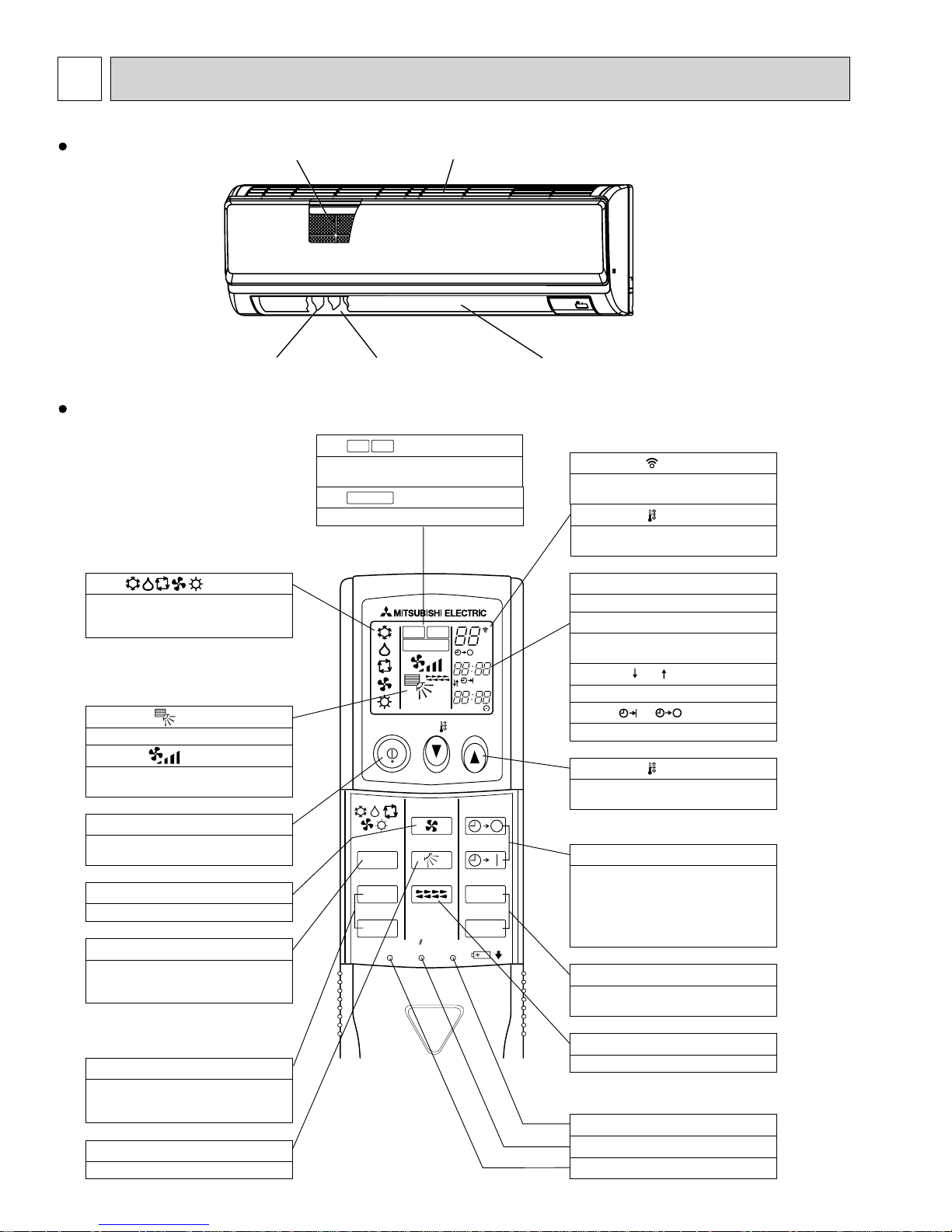
PART NAMES AND FUNCTIONS
Indoor unit
Filter
Louver
Wireless remote controller
display
OPERATION MODE display
Operation mode display indicates which
operation mode is in effect.
display
The vertical direction of air flow is indicated.
display
FAN SPEED display indicates which fan
speed has been selected.
ON/OFF button
The unit is turned ON and OFF alternately
each time the button is pressed.
FAN SPEED SELECT button
Used to change the fan speed.
MODE SELECT button
Used to switch the operation mode between
cooling, drying, fan, heating and auto mode.
+ In case the outdoor unit is cool only type,
the heating and auto mode are not
available.
CHECK-TEST RUN button
Only press this button to perform an
inspection check or test operation.
Do not use it for normal operation.
VANE CONTROL button
Used to change the air flow
Air intake
Air outlet
CHECK
TEST RUN
display
CHECK and TEST RUN display indicate that
the unit is being checked or test-run.
MODEL SELECT
Blinks when model is selected.
display
CHECK
TEST RUN
MODEL SELECT
NOT AVAILABLE
ON/OFF TEMP
FAN
MODE
CHECK
VAN E
LOUVER
TEST RUN
RESETSET CLOCK
°F
°C
AMPM
AMPM
AUTO STOP
AUTO START
h
min
Vane
display
Lights up while the signal is transmitted to
the indoor unit when the button is pressed.
display
SET TEMP. display indicates the set desired
temperature.
CLOCK display
Displays the current time.
TIMER display
Displays when in timer operation or when
setting timer.
“ ” “ ” display
Displays the order of timer operation.
“ ” “ ” display
Displays whether timer is on or off.
button
SET TEMPERATURE button sets any desired
room temperature.
TIMER CONTROL buttons
AUTO STOP (OFF timer): when this switch is
set, the air conditioner will be automatically
stopped at the preset time.
AUTO START (ON timer): when this switch is
set, the air conditioner will be automatically
started at the preset time.
h and min buttons
Buttons used to set the “hour and minute” of
the current time and timer settings.
LOUVER button
Changes left/right airflow direction.
(Not available for this model.)
CLOCK button
RESET button
SET button
2
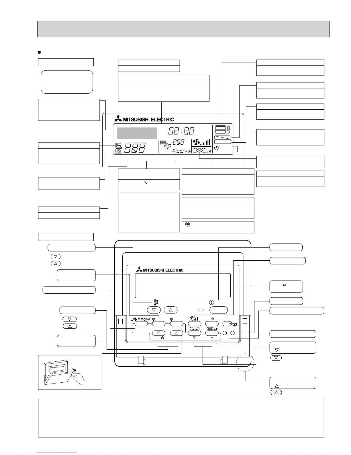
Wired remote controller
Display Section
For purposes of this explanation,
all parts of the display are shown
as lit. During actual operation, only
the relevant items will be lit.
Identifies the current operation
Shows the operating mode, etc.
*Multilanguage display is available.
“Centrally Controlled” indicator
Indicates that operation from the
remote controller has been prohibited by a master controller.
“Timer is Off” indicator
Indicates that the timer is off.
Temperature Setting
Shows the target temperature.
Operation Section
Temperature setting buttons
Down
Up
Timer Menu button
(Monitor/Set button)
Mode button (Return button)
Day-of-Week
Shows the current day of the week.
Time/Timer Display
Shows the current time, unless the simple or Auto Off
timer is set.
If the simple or Auto Off timer is set, the time to be
switched off is shown.
TIME SUN MON TUE WED THU FRI SAT
TIMER
AFTER
ERROR CODE
°F°C
Hr
AFTER
°F°C
ONLY1Hr.
Up/Down Air Direction indicator
The indicator shows the direction of the outcoming airflow.
“One Hour Only” indicator
Displayed if the airflow is set to
Low or downward during COOL
or DRY mode. (Operation varies
according to model.)
The indicator goes off in one hour,
at which time the airflow direction
also changes.
Room Temperature display
Shows the room temperature. The room
temperature display range is 46–102°F.
The display blinks if the temperature
is less than 46°F or 102°F or more.
Louver display
Indicates the action of the swing louver.
Does not appear if the louver is not
running.
(Power On indicator)
Indicates that the power is on.
ON
OFF
FUNCTION
FILTER
WEEKLY
SIMPLE
AUTO OFF
“Sensor” indication
Displayed when the remote controller
sensor is used.
“Locked” indicator
Indicates that remote controller buttons have been locked.
“Clean The Filter” indicator
To be displayed on when it is time to
clean the filter.
Timer indicators
The indicator comes on if the corresponding timer is set.
Fan Speed indicator
Shows the selected fan speed.
Ventilation indicator
Appears when the unit is running in
Ventilation mode.
ON/OFF button
Fan Speed button
Filter button
(<Enter> button)
Set Time buttons
Back
Ahead
Timer On/Off button
(Set Day button)
Opening the
lid
Note:
“PLEASE WAIT” message
This message is displayed for approximately 3 minutes when power is supplied to the indoor unit or when the unit is recovering from a power failure.
“NOT AVAILABLE” message
This message is displayed if an invalid button is pressed (to operate a function that the indoor unit does not have).
If a single remote controller is used to operate multiple indoor units simultaneously that are different types, this message will not be displayed as
far as any of the indoor units is equipped with the function.
TEMP.
MENU
BACK DAY
MONITOR/SET
PAR-21MAA
CLOCK
ON/OFF
33
ON/OFF
FILTER
CHECK
OPERATION
Built-in temperature sensor
CLEAR
TEST
Test Run button
Check button (Clear button)
Airflow Up/Down button
Louver button
( Operation button)
To return operation
number
Ventilation button
( Operation button)
To go to next operation
number
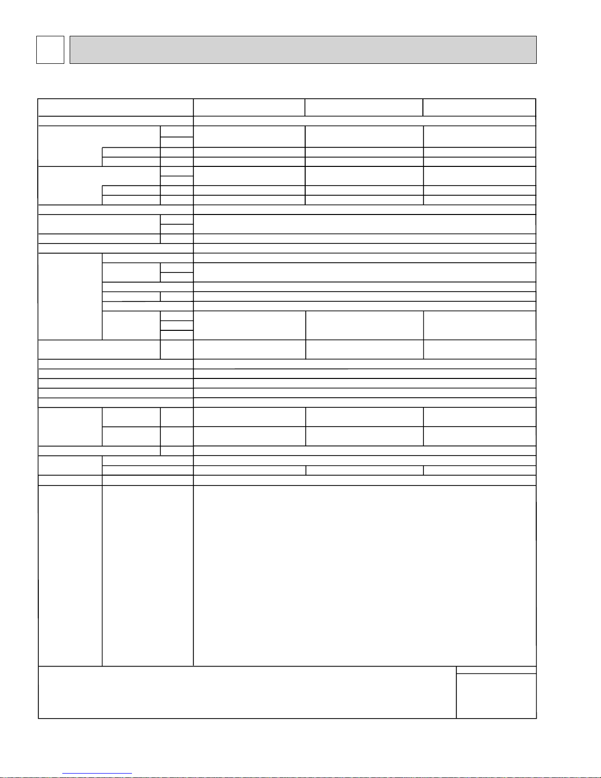
2
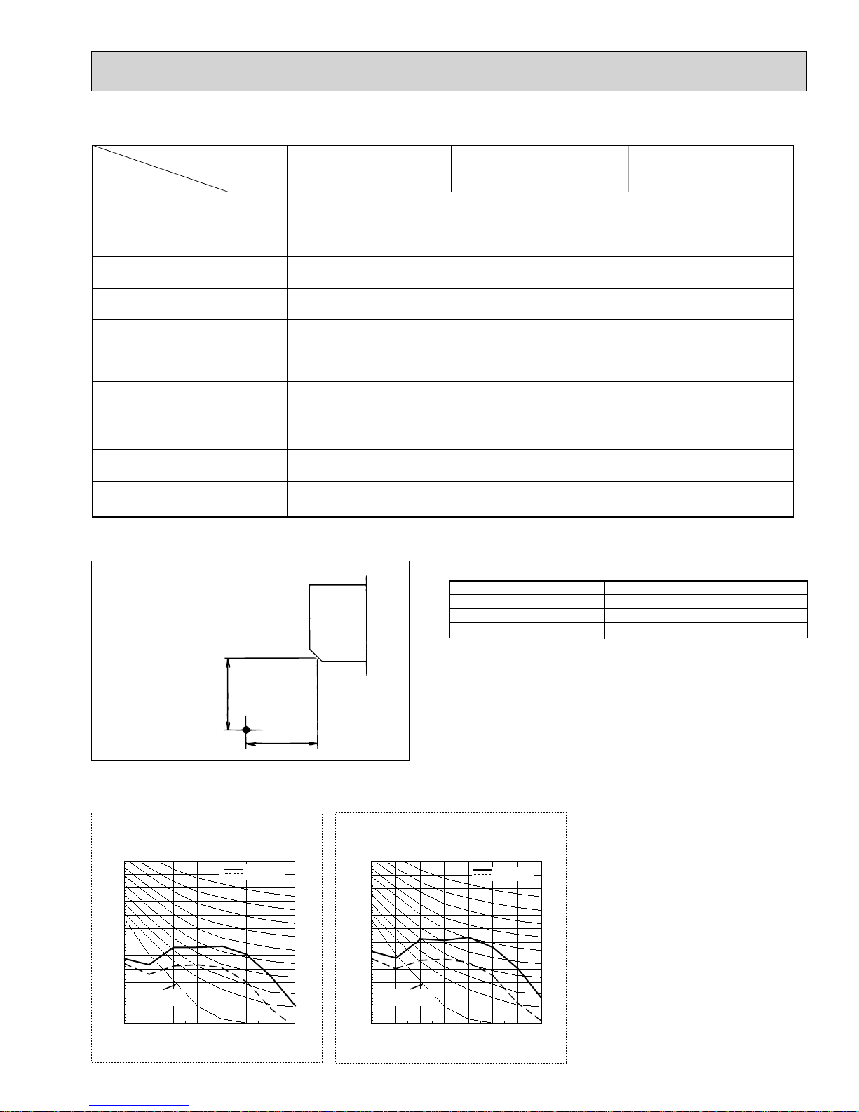
SPECIFICATION
2-1. Specifi cations
Service Ref.
Power source
Cooling capacity
(Nominal)
Power input
Heating capacity
(Nominal )
External finish
External dimension H × W × D
Net weight
Heat exchanger
Fan
Noise level (Low-Mid-High)
(measured in anechoic room)
Insulation material
Air filter
Protection device
Refrigerant control device
Connectable outdoor unit
Diameter of
refrigerant pipe
Field drain pipe size
Standard
attachment
Optional parts
Remarks
Current input
Power input
Current input
Type × Quantity
External
static press.
Motor type
Motor output
Driving mechanism
Airflow rate
(Low-Mid-High)
Liquid
Gas
Document
Accessory
External heater adapter
Installation
*1
*1
*2
*2
(R410A)
(R22)
(R410A)
(R22)
kW
Btu/h
kW
A
kW
Btu/h
kW
A
mm
in.
kg (lb)
Pa
mmH
2
kW
3
/min
m
L/s
cfm
dB <A>
mm (in.)
mm (in.)
mm (in.)
PKFY-P12NHMU-E
PKFY-P15NHMU-E
PKFY-P18NHMU-E
1-phase 208-230V 60Hz
3.5
12,000
0.03
0.30
4.0
13,500
0.03
0.30
4.4
15,000
0.03
0.30
5.0
17,000
0.03
0.30
5.3
18,000
0.03
0.30
5.9
20,000
0.03
0.30
Plastic, MUNSELL (1.0Y 9.2/0.2)
295 × 898 × 249
11-5/8" × 35-3/8" × 9-13/16"
13 (29)
Cross fin (Aluminum fin and copper tube)
Line flow fan × 1
0
O
0
DC motor
0.030
Direct-drive
9 - 10 - 11
150 - 167 - 183
320 - 355 - 390
34 - 38 - 42
9 - 10.5 - 11.5
150 - 175 - 192
320 - 370 - 405
34 - 38 - 42
9 - 10.5 - 12
150 - 175 - 200
320 - 370 - 425
36 - 41 - 45
Polyethylene sheet
PP honeycomb
Fuse
LEV
R410A, R22 CITY MULTI
ø6.35 (ø1/4")
ø6.35 (ø1/4")
ø12.7 (ø1/2")
ø12.7 (ø1/2")
Flare
Flare
Flare
Flare
ø6.35 (ø1/4")
ø6.35 (ø1/4")
ø12.7 (ø1/2")
ø12.7 (ø1/2")
Flare
Flare
Flare
Flare
ø6.35 (ø1/4")
ø9.52 (ø3/8")
ø12.7 (ø1/2")
ø15.88 (ø5/8")
I.D. 16mm (5/8")
Installation Manual, Instruction Book
—
—
—
PAC-YU25HT
Details on foundation work, insulation work, electrical wiring, power source switch, and other items shall be referred to
the Installation Manual.
Flare
Flare
Flare
Flare
*3
*3
Note :
Pipe length :
Level difference :
* Due to continuing improvement, above specification may be subject to change without notice.
*1 Nominal cooling conditions
Indoor :
Outdoor :
80°FDB/67°FWB (26.7°CDB/19.4°CWB)
95°FDB (
25 ft. (7.6 m)
0 ft (
35°CDB)
0 m)
*2 Nominal heating conditions
70°FDB(21°CDB)
47°FDB/43°FWB (8.3°CDB/6.1°CWB)
25 ft. (7.6 m)
0 ft (0 m)
*3 Connect the joint
(purchased locally) for R22
Unit converter
kcal/h = kW × 860
Btu/h = kW × 3,412
3
cfm = m
lb = kg/0.4536
*Above specification data is
subject to rounding variation.
/min × 35.31
4
2-2. Electrical parts specifi cations
Service Ref.
Parts name
Room temperature
thermistor
Liquid pipe thermistor
Gas pipe thermistor
Fuse
(Indoor controller board)
Fan motor
Vane motor
(with limit switch)
Linear expansion valve
Power supply terminal
block
Transmission terminal
block
MA remote controller
terminal block
2-3. Sound levels
Symbol
TH21
TH22
TH23
TH24
FUSE
MF
MV
LEV
TB2
TB5
TB15
PKFY-P12NHMU-E PKFY-P15NHMU-E
PKFY-P18NHMU-E
Resistance 30°F/15.8k, 50°F/9.6k, 70°F/6.0k, 80°F/4.8k, 90°F/3.9k, 100°F/3.2k
Resistance 30°F/15.8k, 50°F/9.6k, 70°F/6.0k, 80°F/4.8k, 90°F/3.9k, 100°F/3.2k
Resistance 30°F/15.8k, 50°F/9.6k, 70°F/6.0k, 80°F/4.8k, 90°F/3.9k, 100°F/3.2k
250V 3.15A
8-Pole Output 30W / RCOJ30-CK
MSFBC20 DC12V
DC12V Stepping motor drive
Port :3.2 (0~2000pulse)
(L1, L2, GR) 250V 20A
(M1, M2, S) 250V 20A
(1, 2) 250V 10A
3.3 ft.
(1m)
Measurement location
* Measured in anechoic room.
2-4. NC curves
PKFY-P12, 15NHMU-E
External static pressure : 0Pa
Power source : 208,230V, 60Hz
70.0
MPa
65.0
60.0
55.0
50.0
45.0
40.0
35.0
30.0
25.0
Approximate minimum
20.0
audible limit on
continuous noise
15.0
10.0
OCTAVE BAND PRESSURE LEVEL (dB) 0dB = 20
63 125 250 500 1k 2k 4k 8k
OCTAVE BAND CENTER FREQUENCIES(Hz)
High speed
Low speed
3.3 ft.
(1m)
PKFY-P18NHMU-E
External static pressure : 0Pa
Power source : 208,230V, 60Hz
70.0
65.0
NC60
NC50
NC40
NC30
NC20
60.0
55.0
50.0
45.0
40.0
35.0
30.0
25.0
Approximate minimum
20.0
audible limit on
continuous noise
15.0
10.0
OCTAVE BAND PRESSURE LEVEL (dB) 0dB = 20MPa
63 125 250 500 1k 2k 4k 8k
OCTAVE BAND CENTER FREQUENCIES(Hz)
Service Ref.
PKFY-P12NHMU-E
PKFY-P15NHMU-E
PKFY-P18NHMU-E
High speed
Low speed
Sound level at anechoic room : Low-Middle-High
Sound level dB (A)
34-38-42
34-38-42
36-41-45
NC60
NC50
NC40
NC30
NC20
55
3
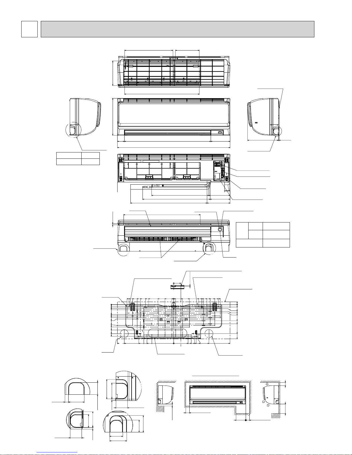
OUTLINES AND DIMENSIONS
PKFY-P12, 15, 18NHMU-E
Left side
D
Knockout hole
for left piping
Sleeve
(purchased locally)
:2-1/2~:3-1/8
(:65~:80)
Through hole
:2-1/2~:3-1/8
(:65~:80)
Knockout hole
for lower piping
7-3/4(197)
11-5/8(295)
5/16(8)
2-1/8
(55)
15-3/16(387)
23-9/16(599)
7-1/2(192)
Top side
Front side
Unit : inch (mm)
Mount board
Right side
A
1/4F (:6.35)
1/2F (:12.7)
:
5/8 (:16) I.D
3/16(5)9-13/16(249)
Vane(auto)
27-1/16(688)
35-3/8(898)
Front side(Grille open)
17-15/16(457)Gas pipe
21-3/16(539)Liquid pipe
24(610)Drain hose
Under side
24-1/16(612)
Operation lamp
6-1/16(155)
6-5/8(169)
6-3/16(158)
7-3/16(184)
Knockout hole
for right piping
Terminal block for power supply
Terminal block for transmission
Terminal block for
MA-remote controller
Emergency operation switch
(cooling/heating)
DEFROST/STAND BY lamp
Refrigerart
Piping
Liquid pipe
Gas pipe
Drain hose
C
Louver(manual)
Knockout hole
for lower piping
Receiver
B
77-
:
3/16(:5.1)
Tapping
screw hole
0
5/8(16)
1-1/16(28.5)
1-9/16(41)
3-1/16(78.5)
3-9/16(91)
4-1/16(103.5)
4-9/16(116)
6-1/2(166)
7(178.5)
8(203.5)
9-1/8(232.5)
9-15/16(253.5)
Wall hole
for
left rear
piping
Knockout hole for piping
2-11/16(69)
1-11/16(43)
2-3/16(56)
3/16(6)
1-3/4(46)
2-5/16(60)
1-11/16(43)
2-3/16(56)7/16(12.5)
A
C
2-3/16(56)
1-3/4(46)
3/16(6)
14-5/8(372.3)
14(356.3)
15-1/2(394)
17-5/8(449)
1-11/16(43)
4-:5/16(:9) Bolt hole
12-7/8(327.5)
10-3/8(265)
11-7/16(291.5)
7-13/16(200)
8-13/16(225)
8-3/8(213)
9-5/16(238)
6-13/16(174)
10-15/16(278.3)
D
2-5/16(59)
1-11/16(43)
B
0
4-7/8(125)
2-3/4(70)
0
9/16(15)
9/16(15)
0
Knockout hole for
rear piping
2-3/4×12-3/16(70×310)
Min.1/4(7)
6
Center measurement hole :3/32(:2.5)
Mount board
2-1/4(58)
5/32(3.8)
11-7/16(291.5)
10-3/8(265)
9-5/16(238)
8-13/16(225)
7-13/16(200)
2-3/4(70)
4-7/8(125)
4-1/2(115)
5-1/2(140)
6-9/16(167)
11-1/16(281)
7-9/16(193.5)
7-1/16(180.3)
Required space(Indoor unit)
Min.1-31/32(50)
14-5/8(372.3)
14(356.3)
12-7/8(237.5)
Wall hole for
right rear piping
Min.8-5/8
(220)
Indoor unit outline
13/16(21.8)
0
3/4(20)
1-1/4(32.7)
2-1/16(53.5)
2-9/16(66)
5(128.5)
6(153.5)
9-1/16(231.5)
10-3/4(273.2)
17-5/8(449)
Min.5-7/8(150)
Air inlet
Min.1-31/32(50)
Air inlet
Air outlet
Min.9-13/16(250)
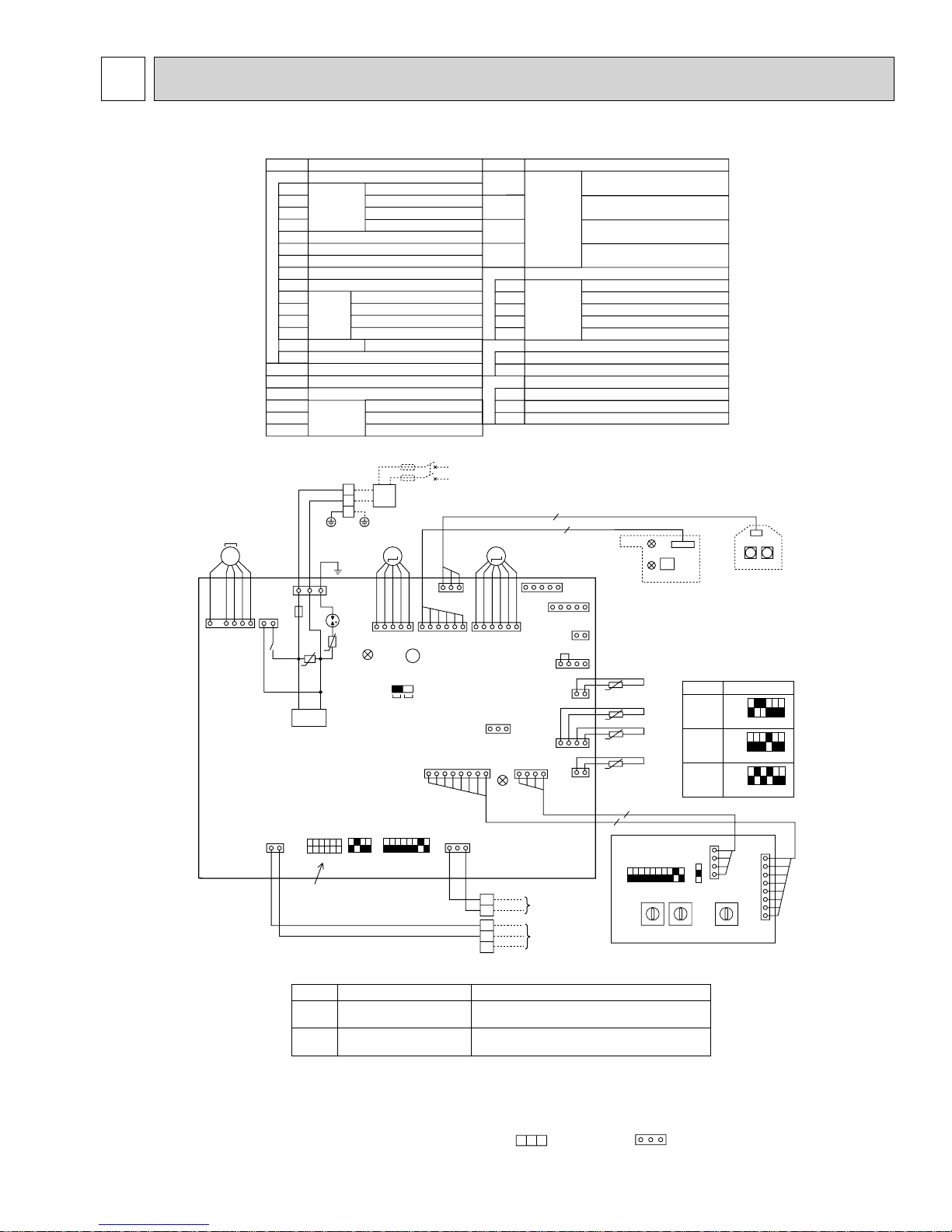
WIRING DIAGRAM4
PKFY-P12, 15, 18NHMU-E
SYMBOL
INDOOR CONTROLLER BOARD
I.B
CN24
CONNECTOR
CN32
CN51
CN52
BZ
BUZZER
DSA SURGE ABSORBER
FUSE FUSE (T3.15AL 250V)
LED1 POWER SUPPLY (I.B)
LED2 POWER SUPPLY (I.B)
SW2
SWITCH
SW3
SW4
SWE
X1 AUX.RELAY
MOV 01.02
VARISTOR
LEV LINEAR EXPANSION VALVE
MF
FAN MOTOR
MV
VANE MOTOR
TB2
TERMINAL
TB5
BLOCK
TB15
NAME
EXTERNAL HEATER
REMOTE SWITCH
CENTRALLY CONTROL
REMOTE INDICATION
CAPACITY CODE
MODE SELECTION
MODEL SELECTOR
DRAIN PUMP (TEST MODE)
DRAIN PUMP (
POWER SUPPLY
TRANSMISSION
MA-REMOTE CONTROLLER
OPTION
SYMBOL
TH21
THERMISTOR
TH22
TH23
TH24
ADDRESS BOARD
A.B
SWA
SWITCH
SW1
SW11
SW12
SW14 BRANCH No.
)
S.B SWITCH BOARD
SWE1
EMERGENCY OPERATION(HEAT)
SWE2
EMERGENCY OPERATION(COOL)
W.B PCB FOR WIRELESS REMOTE CONTROLLER
LED(OPERATION INDICATOR:GREEN)
LED1
LED2
LED(OPERATION FOR HEATING :ORANGE )
RU
RECEIVING UNIT
NAME
ROOM TEMP. DETECTION
32°F/15k,77°F/5.4k)
(
PIPE TEMP. DETECTION / LIQUID
32°F/15k,77°F
(
PIPE TEMP. DETECTION / GAS1
32°F/15k,77°F
(
PIPE TEMP. DETECTION / GAS2
32°F/15k,77°F
(
FAN SPEED SELECTOR
MODE SELECTION
ADDRESS SETTING 1s DIGIT
ADDRESS SETTING 10ths DIGIT
/5.4k)
/5.4k)
/5.4k)
RED
163
MF
MS
3
BLK
FAN
CNMF
(WHT)
~
WHT
BLU
YLW
CN2M(BLU)
POWER SUPPLY
208/230V 60Hz
BREAKER
)
(
16A
)
M
331
LDSWE(A
)
(
BLU
BRN
)
RED
ORN
BLU
BRN
CNRU
(WHT)
ADDRESS
CN81
(RED)
MA-REMOCON
CN3A
(BLU)
1
3
ORN
ORN
6
TB15
TB5
M1
M2
LEV
CN60
(YLW)
CN32
(WHT)
31
LED2
1
2
S
(SHIELD)
61
81
51
51
WHT
YLW
CN24
1
(YLW)
FLOAT SW
CN4F
(WHT)
GAS2
CN2G
(BLK)
LIQUID/GAS1
CN44
(WHT)
ADDRESS
CN42
(RED)
41
INTAKE
CN20
(RED)
TO MA-
REMOTE
CONTROLLER
DC8.7-13V
TO OUTDOOR UNIT
BC CONTROLLER
REMOTE CONTROLLER
DC24-30V
6
I.B
CN52
(GRN)
CN51
(WHT)
21
41
21
41
21
W.B
t
t
t
t
4
8
ON
OFF
11223345678910
A.B
LED2
LED1
TH24
TH23
TH22
TH21
SW1
0
9
8
7
6
5
10ths
DIGIT1sDIGIT
FUSE
CNP
(
BLU
13
X1
M-NET
12
BLU
RED
BLU
GRN/YLW
BLU
RED
BLK
51
)
MOV1
U
U
DC311~339V
RECTIFICATION
SW2
ON
OFF
123456
BLU
See fig:1
CND
(BLK)
<+2>
TB2
GR
DSA
MOV2
L1
L2
SW4
1234
FUSE
PULL
(
16A
BOX
TO NEXT
INDOOR
UNIT
MV LEV
M
RED
YLW
GRN
ORN
51
VANE
CN151
(WHT)
LED1
SWE
OFFBZON
SW3
12345678
LED on indoor board for service
Mark Meaning Function
LED1
LED2
NOTES:
1.At servicing for outdoor unit,always follow the wiring diagram of outdoor unit.
2.In case of using MA-Remote controller, please connect to TB15.
(Remote controller wire is non-polar.)
3.In case of using M-NET, please connect to TB5. (Transmission line is non-polar.)
4.Symbol [S] of TB5 is the shield wire connection.
5.Symbols used in wiring diagram above are, : terminal block, :connecter.
6.The setting of the SW2 dip switches differs in the capacity. for the detail, refer to the fig:1.
Main power supply
Power supply for
MA-Remote controller
Main power supply (Indoor unit:208-230V)
Power on Iamp is lit
Power supply for MA-Remote controller
on Iamp is lit
<+2>Use copper supply wires.
RU
1
2
3
4
LD101(B)
<fig:1>
Models
ADDRESS
(RED)
0
1
9
2
8
3
7
4
6
5
P12
P15
P18
CN43
SWA
OFF
OFF
OFF
ADDRESS
SW14SW11SW12
0
1
F
E
D
C
B
A
8
9
BRANCH
No.
LD SWE(B)
SWE1
SW2
ON
ON
ON
CN82
(RED)
2
3
4
5
6
7
SWE2
S.B
123456
123456
123456
7
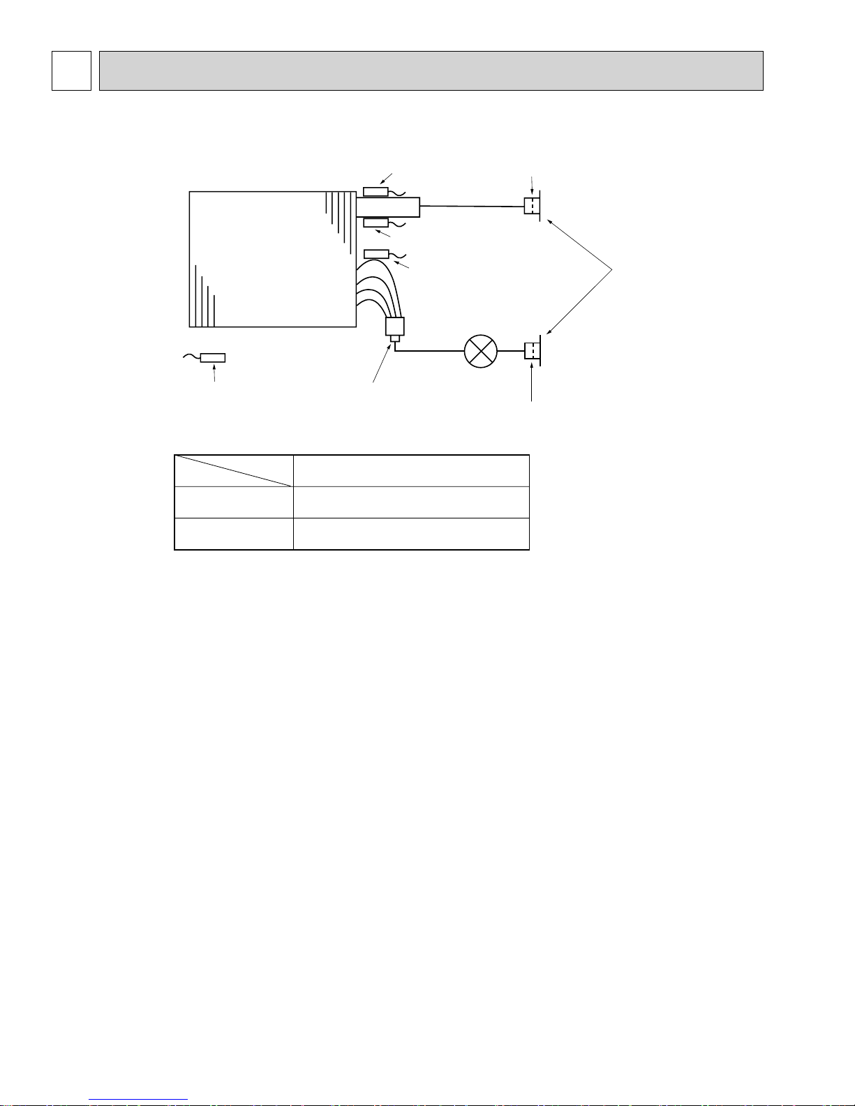
5
REFRIGERANT SYSTEM DIAGRAM
PKFY-P12, 15, 18NHMU-E
Heat exchanger
Room temparature thermistor TH21
Service Ref.
Item
Gas pipe
Liquid pipe
Gas pipe thermistor TH23
Gas pipe thermistor TH24
Liquid pipe thermistor TH22
Linear expansion valve
Strainer1 (#50mesh)
Strainer2 (#100mesh)
Unit : mm (inch)
PKFY-P12,15,18NHMU-E
:12.7(1/2)
:6.35(1/4)
Strainer (#50mesh)
Gas pipe
Flare connection
Liquid pipe
Strainer (#100mesh)
8
 Loading...