

Mitsubishi PKFY-P18NFMU-E, PKFY-P08NAMU-E, PKFY-P06NAMU-E, PKFY-P12NGMU-E, PKFY-P15NGMU-E Technical & Service Manual
...
SPLIT-TYPE, HEAT PUMP AIR CONDITIONERS
TECHNICAL & SERVICE MANUAL
May 2009
No. OC342
REVISED EDITION-C
[Models]
PKFY-P06NAMU-E
PKFY-P08NAMU-E
PKFY-P12NGMU-E
PKFY-P15NGMU-E
PKFY-P18NFMU-E
PKFY-P24NFMU-E
PKFY-P30NFMU-E
PKFY-P12NGMU-E
R410A
/
R22
Revision:
•
"12. RoHS PARTS LIST" has
been modified.
• Please void OC342
REVISED EDITION-B.
NOTE:
• This manual describes only
service data of the indoor
units.
• RoHS compliant products have
<G> mark on the spec name
plate.
• For servicing of RoHS compli-
ant products, refer to the RoHS
PARTS LIST.
CONTENTS
1. DIFFERENCES
2. FEATURES
3. PART NAMES AND FUNCTIONS
4. SPECIFICATION
5. OUTLINES AND DIMENSIONS
6. WIRING DIAGRAM
7.
REFRIGERANT SYSTEM DIAGRAM
8. MICROPROCESSOR CONTROL
9. TROUBLESHOOTING
10. DISASSEMBLY PROCEDURE
11. PARTS LIST
12. RoHS PARTS LIST
.....................................
............................................
...................................
.............................
........................
........................................
.............................
........
..........
....
.......
...........
16
20
22
23
30
39
48
56
2
3
6
9
Revision :
"12. RoHS PARTS LIST" has been modifi ed on page 61.
Page Revise point Service Ref.
1
61
All parts
No. 1~9
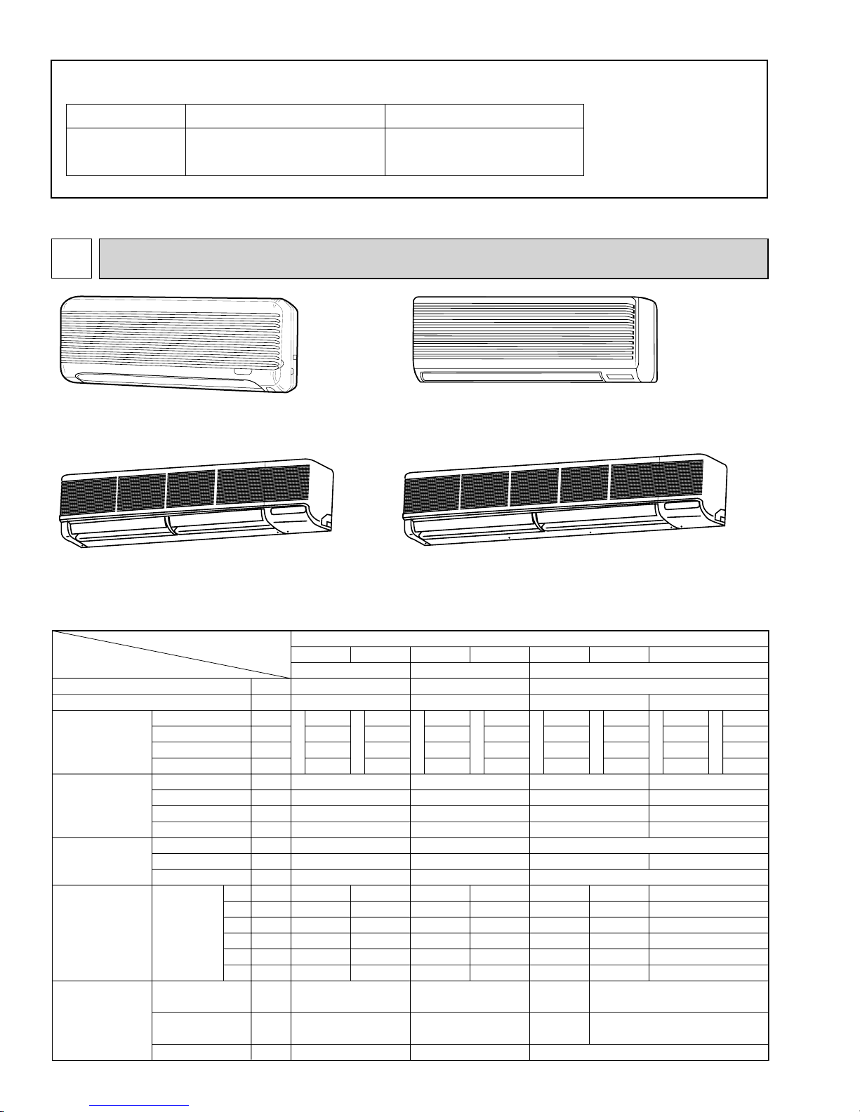
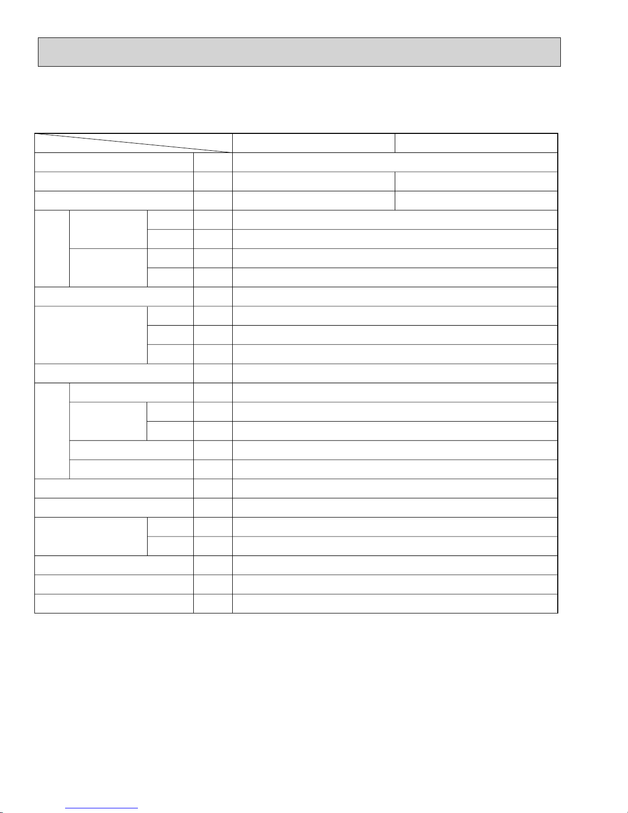
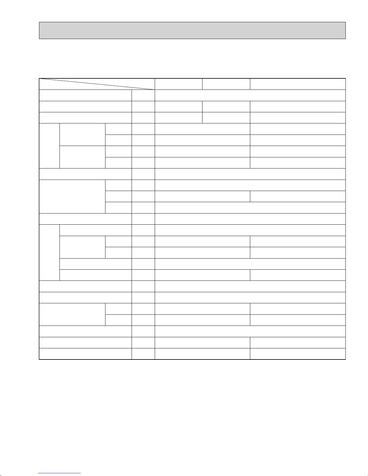
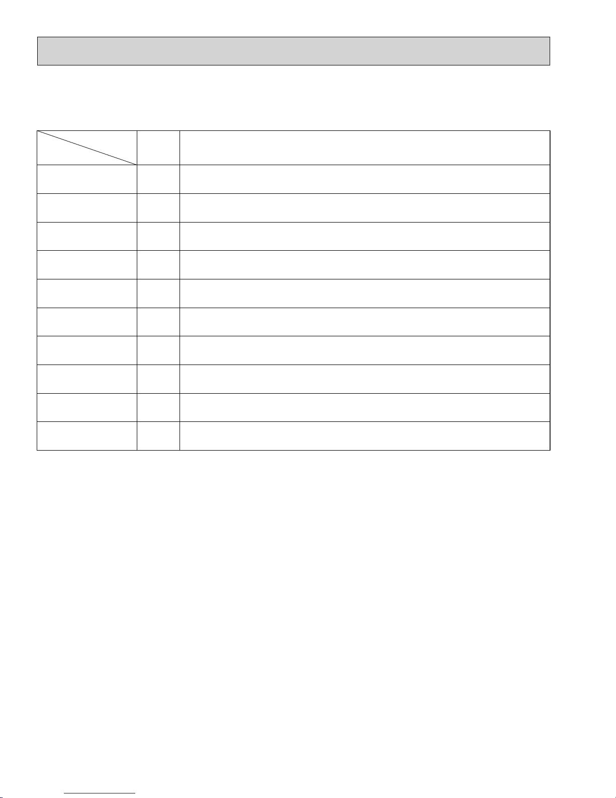
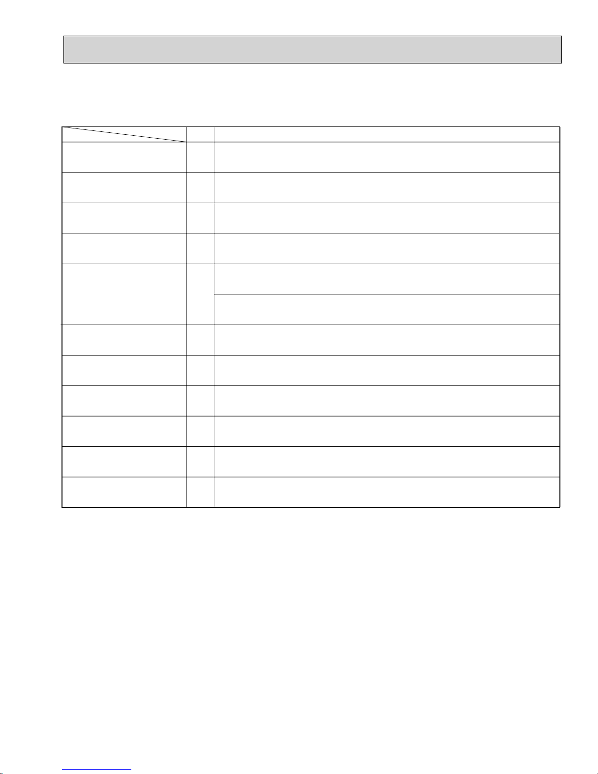
DIFFERENCES
PKFY-P06NAMU-E
PKFY-P08NAMU-E
Indoor Unit
PKFY-P18/24/30NFMU-E
PKFY-P12NGMU-E
PKFY-P15NGMU-E
Indoor Unit
PKFY-P18NFMU-E
PKFY-P24NFMU-E
Indoor Unit
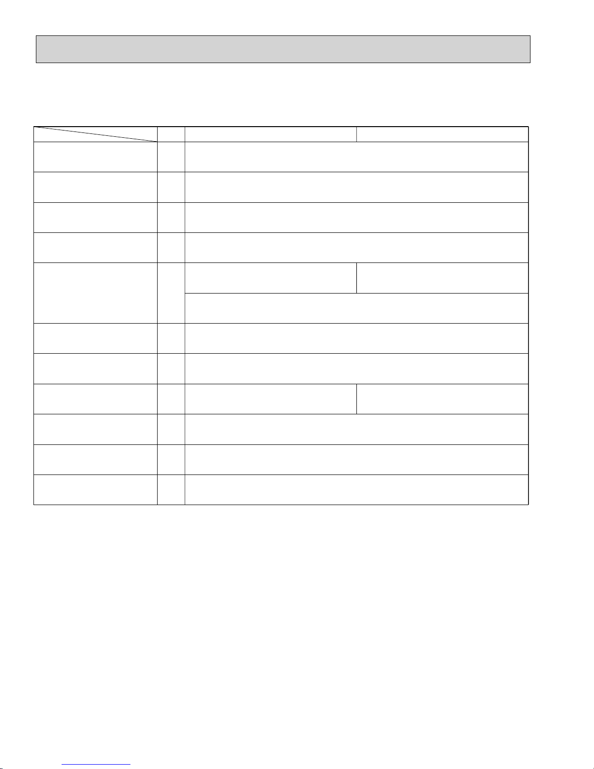
Differences among the models of PKFY series.
1
2
3
4
5
6
Model
—
—
CFM
CFM
CFM
CFM
dB
dB
dB
dB
in.
in.
in.
—
—
—
—
—
—
in.
in.
in.
Item
Fan
Fan speed
Air flow
Noise level
Out dimension
Controller board
Pipe dimension
High
Medium 1
Medium 2
Low
High
Medium 1
Medium 2
Low
Height
Width
Depth
SW2
Gas side
Liquid side
Drain(unit side)
P06
NAMU-E
Lineflow fan × 1
4 speeds type
210
D
R
Y
OFF
OFF
OFF
200
180
170
11- 5/8
32-1/8
6-1/4
ON
—
—
O.D. 5/8"
W
E
T
36
35
33
32
1/2"
1/4"
P08
190
180
170
160
ON
OFF
ON
OFF
—
—
P12
NGMU-E
Lineflow fan × 1
4 speeds type
410
D
R
Y
OFF
OFF
OFF
OFF
W
370
E
340
T
280
42
40
36
32
13-3/8
39
9-1/4
ON
ON
1/2"
1/4"
O.D. 13/16"
2
PKFY-P30NFMU-E
Indoor Unit
PKFY-
P15
370
330
300
250
OFF
OFF
OFF
ON
OFF
OFF
P18
2 speeds type
640
D
—
R
—
Y
490
55-1/8
OFF
ON
OFF
ON
OFF
OFF
1/2" / 5/8"
(Compatible)
1/4" / 3/8"
(Compatible)
P24
NFMU-E
Lineflow fan × 2
570
W
—
E
—
T
440
45
—
—
39
13-3/8
9-1/4
ON
OFF
ON
ON
OFF
OFF
O.D. 13/16"
P30
2 speeds type
990
D
—
R
—
Y
780
66-1/8
OFF
OFF
OFF
OFF
ON
OFF
5/8"
3/8"
49
—
—
46
W
890
—
E
—
T
700

2
FEATURES
PKFY-P06NAMU-E
PKFY-P08NAMU-E
Indoor Unit
Model Cooling capacity / Heating capacity
PKFY-P06NAMU-E 6,000 / 6,700 Btu/h
PKFY-P08NAMU-E 8,000 / 9,000 Btu/h
1. Compact Design
• Compact 11-5/8 inch (29.5cm) high body fits snugly in even limited spaces.
• Light weight 19lbs (8.5kg) unit easy to transport and install.
2. Auto-flap shutter enhances good looks
With a simple flick of the OFF switch, the air outlet can be closed off with a shutter. The shutter also functions as a flap
during operation to adjust the air flow angle, with “Auto Angle” securing a comfortable air flow.
3. Quiet operation
4. The intake grille filter can be completely removed allowing easy cleaning
3
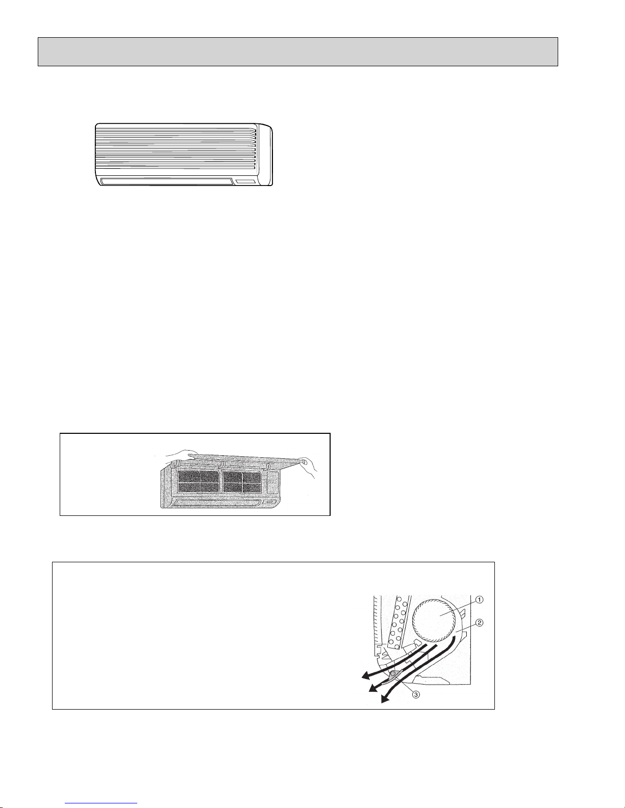
PKFY-P12NGMU-E
PKFY-P15NGMU-E
Indoor Unit
Model Cooling capacity / Heating capacity
PKFY-P12NGMU-E 12,000 / 13,500 Btu/h
PKFY-P15NGMU-E 15,000 / 17,000 Btu/h
1. Compact Design
Units have now been downsized to require minimal wall space.
A 20% reduction in width 39 inch (990mm) compared to previous models means that installation is possible in very narrow
spaces.
2. Auto-flap shutter enhances good looks
With a simple flick of the OFF switch, the air outlet can be closed off with a shutter. The shutter also functions as a flap
during operation to adjust the air flow angle, with “Auto Angle” securing a comfortable air flow.
3. The intake grille filter can be completely removed allowing easy cleaning
(Can be washed in water)
• Front grille
opens out
4. Quiet operation
• Airflow passage configuration that assures quiet operation
By changing fan intervals, quiet operation is achieved
without reduction in airflow. Optimal design of the
airflow passage gives a shortened fan diameter
and allows a highly compact installation.
2 Thanks to a highly practical casing configuration,
airflow generated by the fan is distributed uniformly.
3 Due to careful positioning of the vertical vane axis,
air is blown evenly from the outlet. This prevents mixing
with secondary air and also suppresses condensation.
1 The unit incorporates a random pitch cycling fan.
4
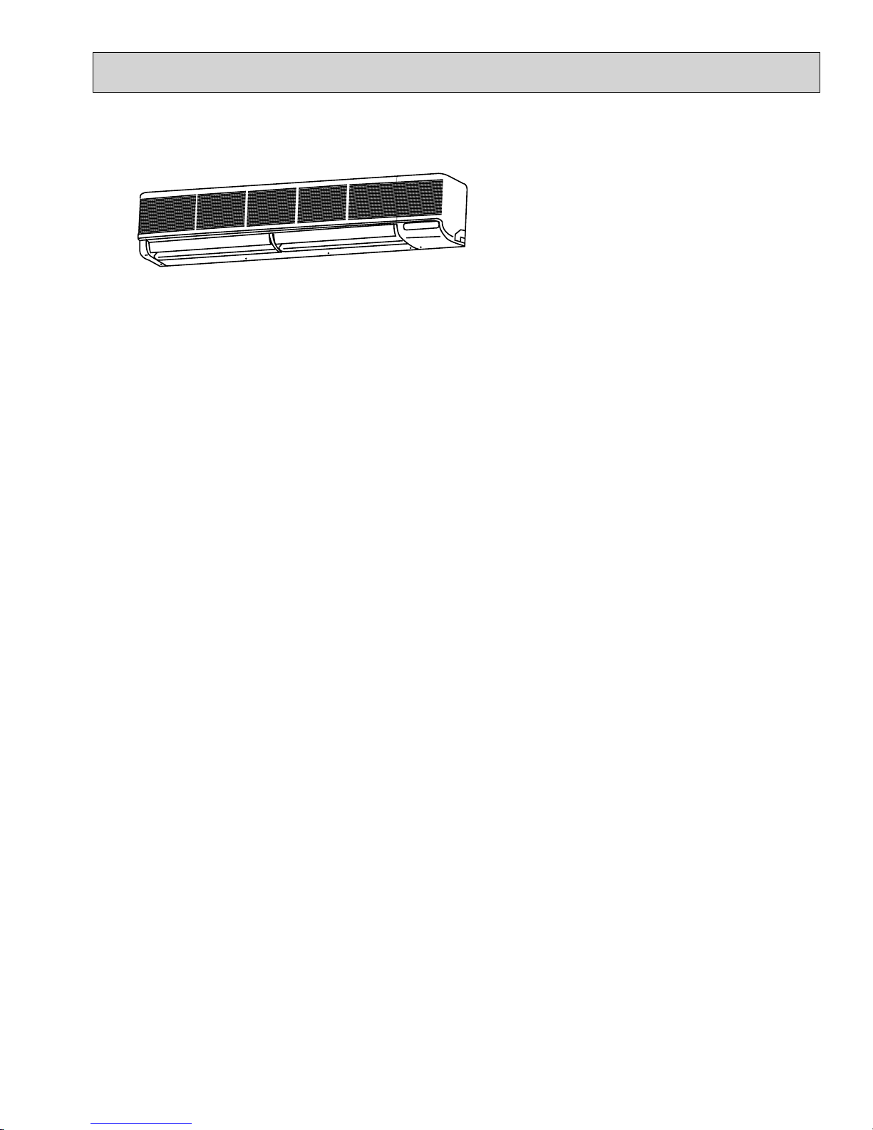
PKFY-P18NFMU-E
PKFY-P24NFMU-E
PKFY-P30NFMU-E
PKFY-P30NFMU-E
Indoor Unit
Models Cooling capacity / Heating capacity
PKFY-P18NFMU-E 18,000 / 20,000 Btu/h
PKFY-P24NFMU-E 24,000 / 27,000 Btu/h
PKFY-P30NFMU-E 30,000 / 34,000 Btu/h
1. A further refinement of comfort with noise suppression
Remarkably low-noise operation has been achieved through the development of a “near -silent” fan and the design
which minimizes air flow resistance.
2. Auto flap shutter
With a simple flick of the OFF switch, the air outlet can be closed off with a shutter. The shutter also functions as a flap
during operation to adjust the air flow angle, with “Auto Angle” securing a comfortable air flow.
3. Easily removable filter
The presence of thumbscrews on the filters means that the filters can be quickly and smoothly removed.
5
3
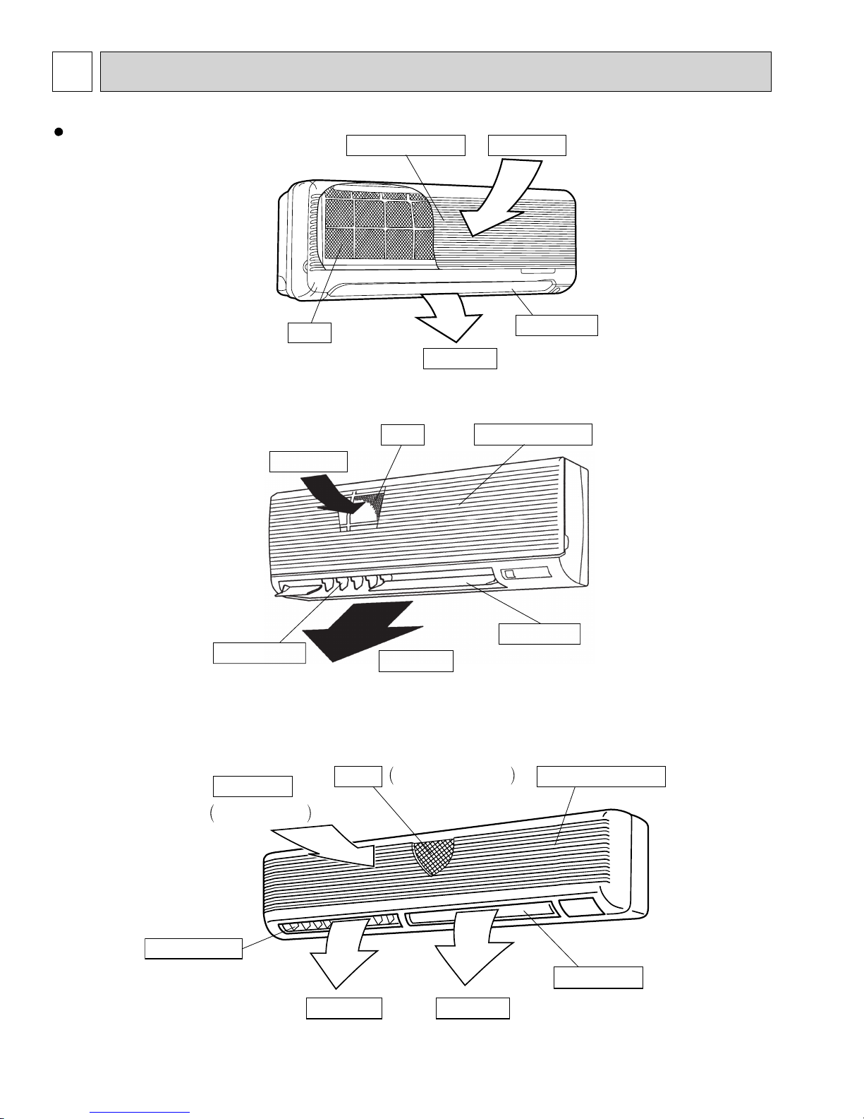
PART NAMES AND FUNCTIONS
Indoor Unit
PKFY-P06NAMU-E
PKFY-P08NAMU-E
PKFY-P12NGMU-E
PKFY-P15NGMU-E
Filter
Air intake
Air intake grille Air intake
Auto vane
Air outlet
Filter
Air intake grille
PKFY-P18NFMU-E
PKFY-P24NFMU-E
PKFY-P30NFMU-E
Guide vane
Air flow can be changed to
horizontally by moving the
Guide vane to the left or right.
Guide vane
Air intake
Room air is
suctioned in here.
Auto vane
Air outlet
Filter Air intake grilles
Removes dust and dirt
from the intake air.
Auto vane
Air outletAir outlet
6
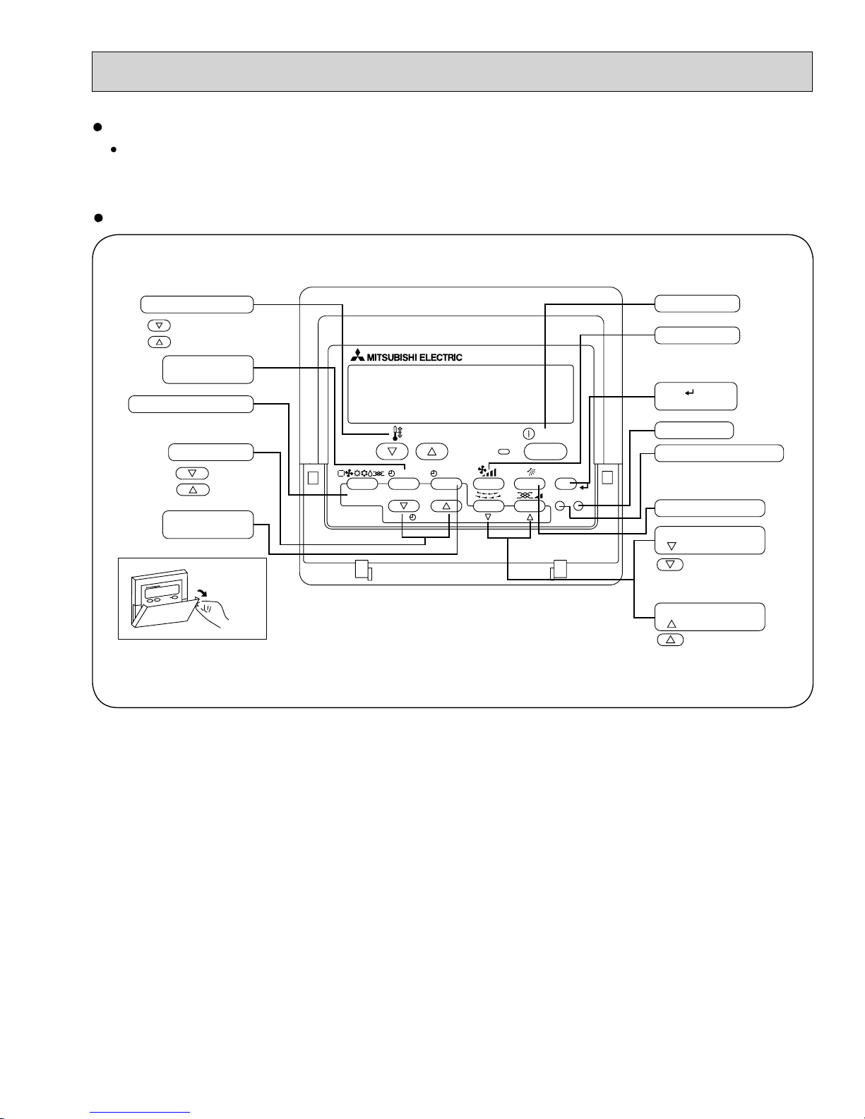
PAR-21MAA
ON/OFF
FILTER
CHECK
OPERATION
CLEAR
TEST
TEMP.
MENU
BACK DAY
MONITOR/SET
CLOCK
ON/OFF
Set Temperature buttons
Down
Up
Timer Menu button
(Monitor/Set button)
Mode button (Return button)
Set Time buttons
Back
Ahead
Timer On/Off button
(Set Day button)
Opening the
door
ON/OFF button
Fan Speed button
Filter button
(<Enter> button)
Test Run button
Check button (Clear button)
Airflow Up/Down button
Louver button
( Operation button)
To preceding operation
number
Ventilation button
(
Operation button)
To next operation number
Remote controller
Once the operation of the unit is set, subsequent operations can only be performed by pressing the ON/OFF button
repeatedly.
Operation buttons
7
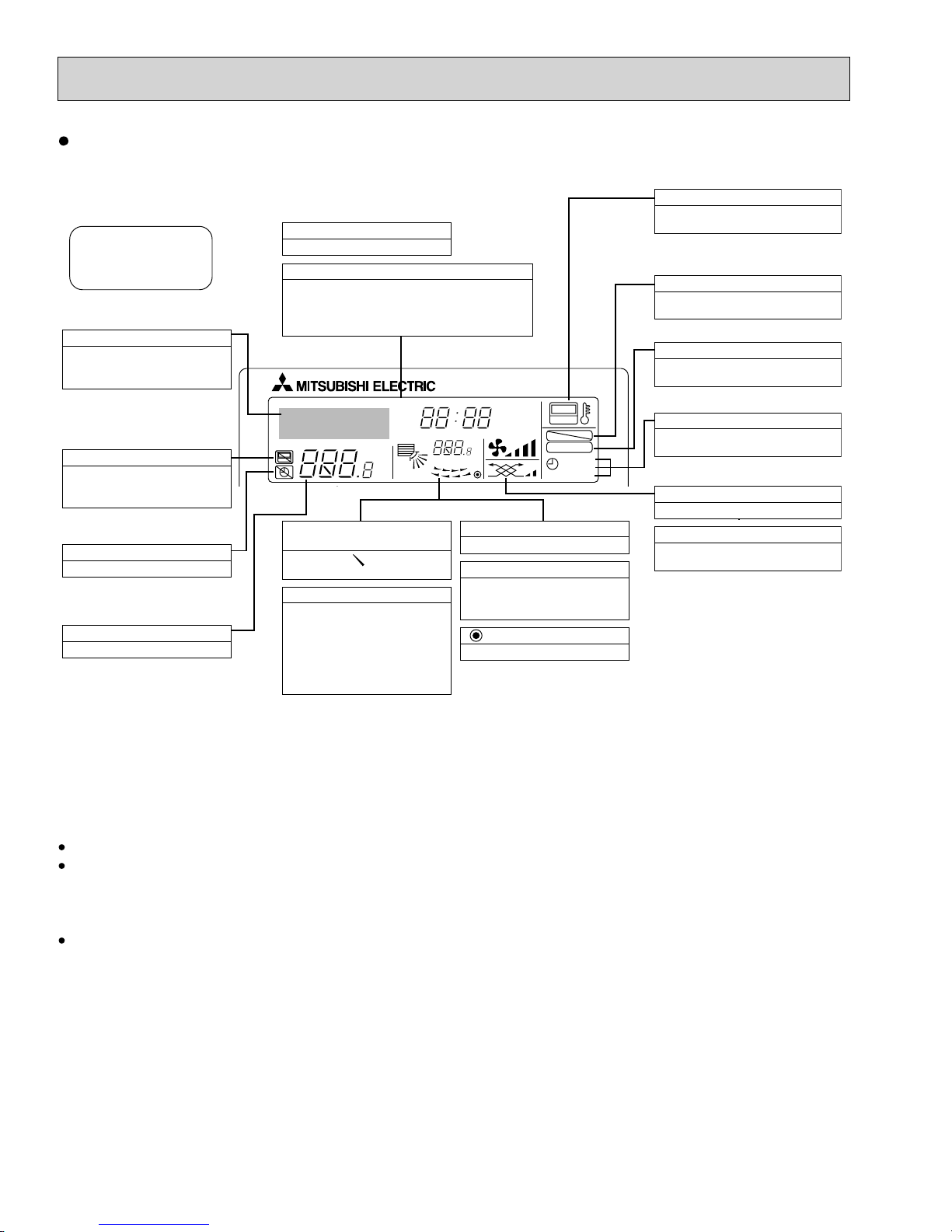
Display
For purposes of this explanation,
all parts of the display are shown
as lit. During actual operation, only
the relevant items will be lit.
Identifies the current operation
Shows the operating mode, etc.
* Multilanguage display is sup-
ported.
“Centrally Controlled” indicator
Indicates that operation of the remote controller has been prohibited by a master controller.
“Timer Is Off” indicator
Indicates that the timer is off.
Temperature Setting
Shows the target temperature.
Day-of-Week
Shows the current day of the week.
Time/Timer Display
Shows the current time, unless the simple or Auto Off
timer is set.
If the simple or Auto Off timer is set, shows the time
remaining.
TIME SUN MON TUE WED THU FRI SAT
TIMER
AFTER
ERROR CODE
°F°C
Hr
AFTER
°F°C
ONLY1Hr.
Up/Down Air Direction indicator
The indicator shows the direction of the outcoming airflow.
“One Hour Only” indicator
Displayed if the airflow is set to
low and downward during COOL
or DRY mode. (Operation varies
according to model.)
The indicator goes off after one
hour, at which time the airflow direction also changes.
Room Temperature display
Shows the room temperature.
Louver display
Indicates the action of the swing
louver. Does not appear if the
louver is stationary.
(Power On indicator)
Indicates that the power is on.
ON
OFF
FUNCTION
FILTER
WEEKLY
SIMPLE
AUTO OFF
“Sensor” indication
Displayed when the remote controller
sensor is used.
“Locked” indicator
Indicates that remote controller buttons have been locked.
“Clean The Filter” indicator
Comes on when it is time to clean the
filter.
Timer indicators
The indicator comes on if the corresponding timer is set.
Fan Speed indicator
Shows the selected fan speed.
Ventilation indicator
Appears when the unit is running in
Ventilation mode.
Caution
Only the Power on indicator lights when the unit is stopped and power supplied to the unit.
If you press a button for a feature that is not installed in the indoor unit, the remote controller will display the “Not Available”
message.
If you are using the remote controller to operate multiple indoor units, this message will appear only if the feature is not
present at every unit connected.
When power is turned ON for the first time, it is normal that “PLEASE WAIT” is displayed on the room temperature indication
(For max. 2minutes). Please wait until this “PLEASE WAIT” indication disappears then start the operation.
8
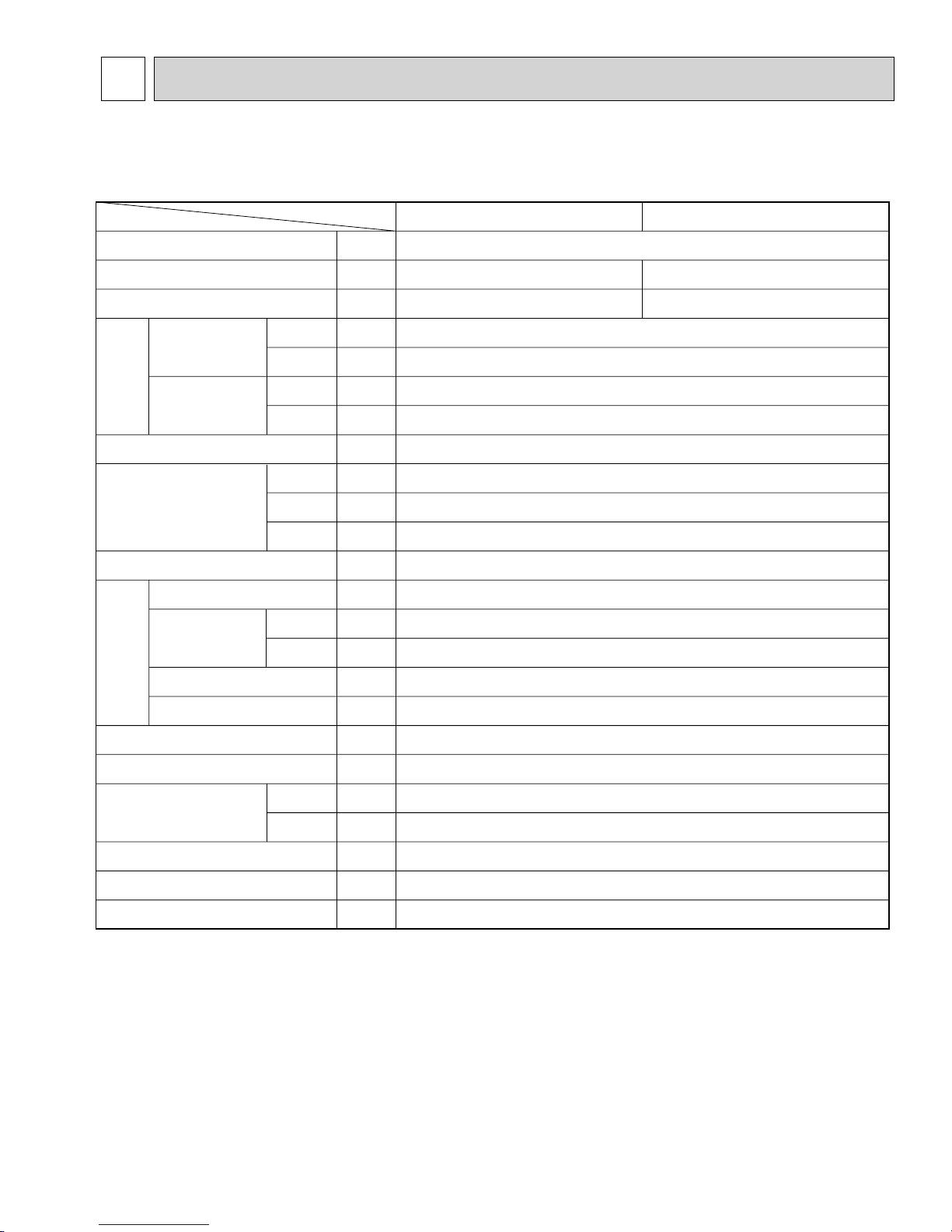
4
SPECIFICATIONS
4-1. SPECIFICATIONS
PKFY-P06NAMU-E
PKFY-P08NAMU-E
Item
Power source
Cooling capacity
Heating capacity
Power Supply
Electric
Starting Current
characteristic
Exterior <munsell symbol>
Out dimensions
Heat exchanger
Fan × No.
Air flow + 2
Fan
Cooling
Heating
Cooling
Heating
Height
Width
Depth
DRY
WET
Unit
:,V,Hz
Btu/h
Btu/h
kW
kW
A
A
—
in.
in.
in.
—
—
CFM
CFM
PKFY-P06NAMU-E
Single phase, 208/230V, 60Hz
6,000
6,700
0.03
0.03
0.15
0.15
Plastic , white : <2.60Y 8.66/0.69>
11- 5/8
32-1/8
6-1/4
Cross fin (Aluminum plate fin and copper tube)
Lineflow fan × 1
170-180-200-210
160-170-180-190
PKFY-P08NAMU-E
8,000
9,000
External static pressure
Fan motor output
Insulator
Air filter
Gas side
Pipe dimensions
Liquid side
Unit drain pipe size
Noise level + 2
Product weight
Note 1. Rating conditions
Cooling : Indoor D.B. 80˚F W.B. 67˚F
Outdoor D.B. 95˚F W.B. 75˚F
Heating : Indoor D.B. 70˚F
Outdoor D.B. 47˚F W.B. 43˚F
w 2. Air flow and the noise level are indicated as Low - Medium2 - Medium1 - High.
Pa
kW
—
—
in.
in.
in.
dB
lbs
0.017
Polyethylene sheet
PP honey comb
1/2"
1/4"
PVC pipe with O.D. 5/8"
32-33-35-36
0
19
9
PKFY-P12NGMU-E
PKFY-P15NGMU-E
Item
Power source
Cooling capacity
Heating capacity
Input
Electric
Current
characteristic
Exterior <munsell symbol>
Out dimensions
Heat exchanger
Fan × No.
Air flow + 2
Fan
Cooling
Heating
Cooling
Heating
Height
Width
Depth
DRY
WET
Unit
:,V,Hz
Btu/h
Btu/h
kW
kW
A
A
—
in.
in.
in.
—
—
CFM
CFM
PKFY-P12NGMU-E
Single phase, 208/230V, 60Hz
12,000
13,500
0.07
0.07
0.34
0.34
Plastic , white : <0.70Y 8.59/0.97>
13-3/8
39
9-1/4
Cross fin (Aluminum plate fin and copper tube)
Lineflow fan × 1
280-340-370-410
250-300-330-370
PKFY-P15NGMU-E
15,000
17,000
External static pressure
Fan motor output
Insulator
Air filter
Gas side
Pipe dimensions
Liquid side
Unit drain pipe size
Noise level + 2
Product weight
Note 1. Rating conditions
Cooling : Indoor : D.B. 80°F W.B. 67°F
outdoor : D.B. 95°F W.B. 75°F
Heating : Indoor : D.B. 70°F
outdoor : D.B. 47°F W.B. 43°F
W 2. Air flow and the noise level are indicated as Low - Medium2 - Medium1 - High.
Pa
kW
—
—
in.
in.
in.
dB
lbs
0.03
Polyethylene sheet
PP honey comb
1/2"
1/4"
PVC pipe with O.D. 13/16"
32-36-40-42
0
35
10
PKFY-P18NFMU-E
PKFY-P24NFMU-E
PKFY-P30NFMU-E
Item
Power source
Cooling capacity
Heating capacity
Input
Electric
Current
characteristic
Exterior <munsell symbol>
Dimensions
Heat exchanger
Type × No.
Air flow
Fan
Low - High
Cooling
Heating
Cooling
Heating
Height
Width
Depth
DRY
WET
Unit
:,V,Hz
Btu/h
Btu/h
kW
kW
A
A
—
in.
in.
in.
—
—
CFM
CFM
PKFY-P18NFMU-E
18,000
20,000
0.09
0.09
0.44
0.44
55-1/8
Cross fin(Aluminum plate fin and copper tube)
490 - 640
440 - 570
PKFY-P24NFMU-E
Single phase, 208V-230V, 60Hz
24,000
27,000
Plastic , white : <3.4Y 7.7/0.8>
13-3/8
9-1/4
Lineflow fan × 2
PKFY-P30NFMU-E
30,000
34,000
0.12
0.12
0.58
0.58
66-1/8
780 - 990
700 - 890
External static pressure
Fan motor output
Insulator
Air filter
Gas side
Pipe dimensions
Liquid side
Unit drain pipe dimension
Noise level Low - High
Product weight
Note 1. Rating conditions
Cooling : Indoor : D.B. 80°F W.B. 67°F
outdoor : D.B. 95°F W.B. 75°F
Heating : Indoor : D.B. 70°F
outdoor : D.B. 47°F W.B. 43°F
Pa
kW
—
—
in.
in.
in.
dB
lbs
0.045
1/2" / 5/8" (compatible)
1/4" / 3/8" (compatible)
39 - 45
53
0
0.070
Polyethylene sheet
PP honey comb
5/8"
3/8"
PVC pipe with O.D. 13/16"
46 - 49
62
11
4-2. ELECTRICAL PARTS SPECIFICATIONS
PKFY-P06NAMU-E
PKFY-P08NAMU-E
Model
Symbol
Parts name
Room temperature
thermistor
TH21
Resistance 30°F/15.8k, 50°F/9.6k, 70°F/6.0k, 80°F/4.8k, 90°F/3.9k, 100°F/3.2k
PKFY-P06/P08NAMU-E
Liquid pipe temperature thermistor
Gas pipe temperature thermistor
Fuse
(Indoor power board)
Fan motor
(with thermal fuse)
Fan motor capacitor
Vane motor
(with limit switch)
Linear expansion valve
Power supply terminal
block
Transmission terminal
block
TH22
TH23
FUSE
MF
C
MV
LEV
TB2
TB5
Resistance 30°F/15.8k, 50°F/9.6k, 70°F/6.0k, 80°F/4.8k, 90°F/3.9k, 100°F/3.2k
Resistance 30°F/15.8k, 50°F/9.6k, 70°F/6.0k, 80°F/4.8k, 90°F/3.9k, 100°F/3.2k
250V 6A
4-Pole Output 8W / PS4N8-KA
1.2μF × 440V
MSFBC20A03 DC12V
DC12V Stepping motor drive
Port dimension :3.2 (0~2000pulse) EDM-40YGME
(L1, L2,GR) 250V 20A
(M1, M2) 250V 10A
12
PKFY-P12NGMU-E
PKFY-P15NGMU-E
Parts name
Model
Symbol
PKFY-P12/P15NGMU-E
Room temperature thermistor
Liquid pipe temperature thermistor
Gas pipe temperature thermistor
Fuse
(Indoor controller board)
Fan motor
(with inner-thermostat)
Fan motor capacitor
Vane motor
Linear expansion valve
Power supply terminal block
TH21
TH22
TH23
FUSE
MF
MV
LEV
TB2
Resistance 30°F/15.8kΩ, 50°F/9.6kΩ, 70°F/6.0kΩ, 80°F/4.8kΩ, 90°F/3.9kΩ, 100°F/3.2kΩ
°
Resistance 30
Resistance 30
Inner-thermostat
C
F/15.8kΩ, 50°F/9.6kΩ, 70°F/6.0kΩ, 80°F/4.8kΩ, 90°F/3.9kΩ, 100°F/3.2kΩ
°
F/15.8kΩ, 50°F/9.6kΩ, 70°F/6.0kΩ, 80°F/4.8kΩ, 90°F/3.9kΩ, 100°F/3.2kΩ
250V 6A
PM4N30-KA 208V/230V 60Hz
4 pole Output 30W
OPEN 25 ± 9 °F
2.0 μF 440V
MP 35 EA DC12V
DC12V Stepping motor drive
Port dimension :3.2 (0 ~ 2000pulse) EDM-40YGME
(L1, L2, GR) 330V 30A
Transmission terminal block
MA remote controller terminal block
TB5
TB15
(M1, M2, S) 250V 20A
(1,2) 250V 10A
13
PKFY-P18NFMU-E
PKFY-P24NFMU-E
PKFY-P30NFMU-E
Parts name
Model
Symbol
PKFY-P18/P24NFMU-E
PKFY-P30NFMU-E
Room temperature thermistor
Liquid pipe temperature thermistor
Gas pipe temperature thermistor
Fuse
(Indoor controller board)
Fan motor
(with inner-thermostat)
Fan motor capacitor
Vane motor
Linear expansion valve
Power supply terminal block
TH21
TH22
TH23
FUSE
MF
C
MV
LEV
TB2
Resistance 30°F/15.8kΩ, 50°F/9.6kΩ, 70°F/6.0kΩ, 80°F/4.8kΩ, 90°F/3.9kΩ, 100°F/3.2kΩ
Resistance 30°F/15.8kΩ, 50°F/9.6kΩ, 70°F/6.0kΩ, 80°F/4.8kΩ, 90°F/3.9kΩ, 100°F/3.2kΩ
Resistance 30°F/15.8kΩ, 50°F/9.6kΩ, 70°F/6.0kΩ, 80°F/4.8kΩ, 90°F/3.9kΩ, 100°F/3.2kΩ
250V 6A
PN4N45-K
208-230V 60Hz
4pole Output 45w
Inner-thermostat
DC12V Stepping motor drive
Port dimension :3.2 (0 ~ 2,000pulse)
EDM-40YGME
OPEN 266 ± 9 °F
2.5440V
MP 35 EA DC12V
(L1, L2, GR) 330V 30A
DC12V Stepping motor drive
Port dimension :5.2 (0 ~ 2,000pulse)
PN4N70-K
208-230V 60Hz
4pole Output 70w
EDM-80YGME
Transmission terminal block
MA remote controller
terminal block
TB5
TB15
(M1, M2, S) 250V 20A
(1,2) 250V 10A
14
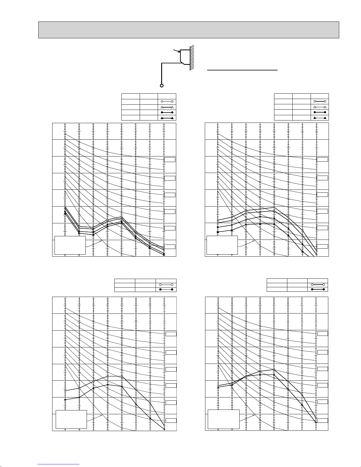
4-3. NOISE CRITERION CURVES
3.3ft
Unit
3.3ft
Wall
Ambient temperature 80°F
High
Low
SPL(dB)
36
35
33
32
PKFY-P06NAMU-E
PKFY-P08NAMU-E
90
80
70
60
50
40
30
APPROXIMATE
20
THRESHOLD OF
HEARING FOR
CONTINUOUS
NOISE
OCTAVE BAND SOUND PRESSURE LEVEL, dB re 0.0002 MICRO BAR
10
63 125 250 500 1000 2000 4000 8000
BAND CENTER FREQUENCIES, Hz
NOTCH
Medium1
Medium2
LINE
NC-70
NC-60
NC-50
NC-40
NC-30
NC-20
High
Low
SPL(dB)
42
40
36
32
PKFY-P12NGMU-E
PKFY-P15NGMU-E
90
80
70
60
50
40
30
APPROXIMATE
20
THRESHOLD OF
HEARING FOR
CONTINUOUS
NOISE
OCTAVE BAND SOUND PRESSURE LEVEL, dB re 0.0002 MICRO BAR
10
63 125 250 500 1000 2000 4000 8000
BAND CENTER FREQUENCIES, Hz
NOTCH
Medium1
Medium2
LINE
NC-70
NC-60
NC-50
NC-40
NC-30
NC-20
High
Low
SPL(dB)39LINE
45
PKFY-P18NFMU-E
NOTCH
PKFY-P24NFMU-E
90
80
70
60
50
40
30
APPROXIMATE
20
THRESHOLD OF
HEARING FOR
CONTINUOUS
NOISE
OCTAVE BAND SOUND PRESSURE LEVEL, dB re 0.0002 MICRO BAR
10
63 125 250 500 1000 2000 4000 8000
BAND CENTER FREQUENCIES, Hz
NC-70
NC-60
NC-50
NC-40
NC-30
NC-20
High
Low
SPL(dB)46LINE
49
PKFY-P30NFMU-E
90
80
70
60
50
40
30
APPROXIMATE
20
THRESHOLD OF
HEARING FOR
CONTINUOUS
NOISE
10
OCTAVE BAND SOUND PRESSURE LEVEL, dB re 0.0002 MICRO BAR
63 125 250 500 1000 2000 4000 8000
BAND CENTER FREQUENCIES, Hz
NOTCH
NC-70
NC-60
NC-50
NC-40
NC-30
NC-20
15
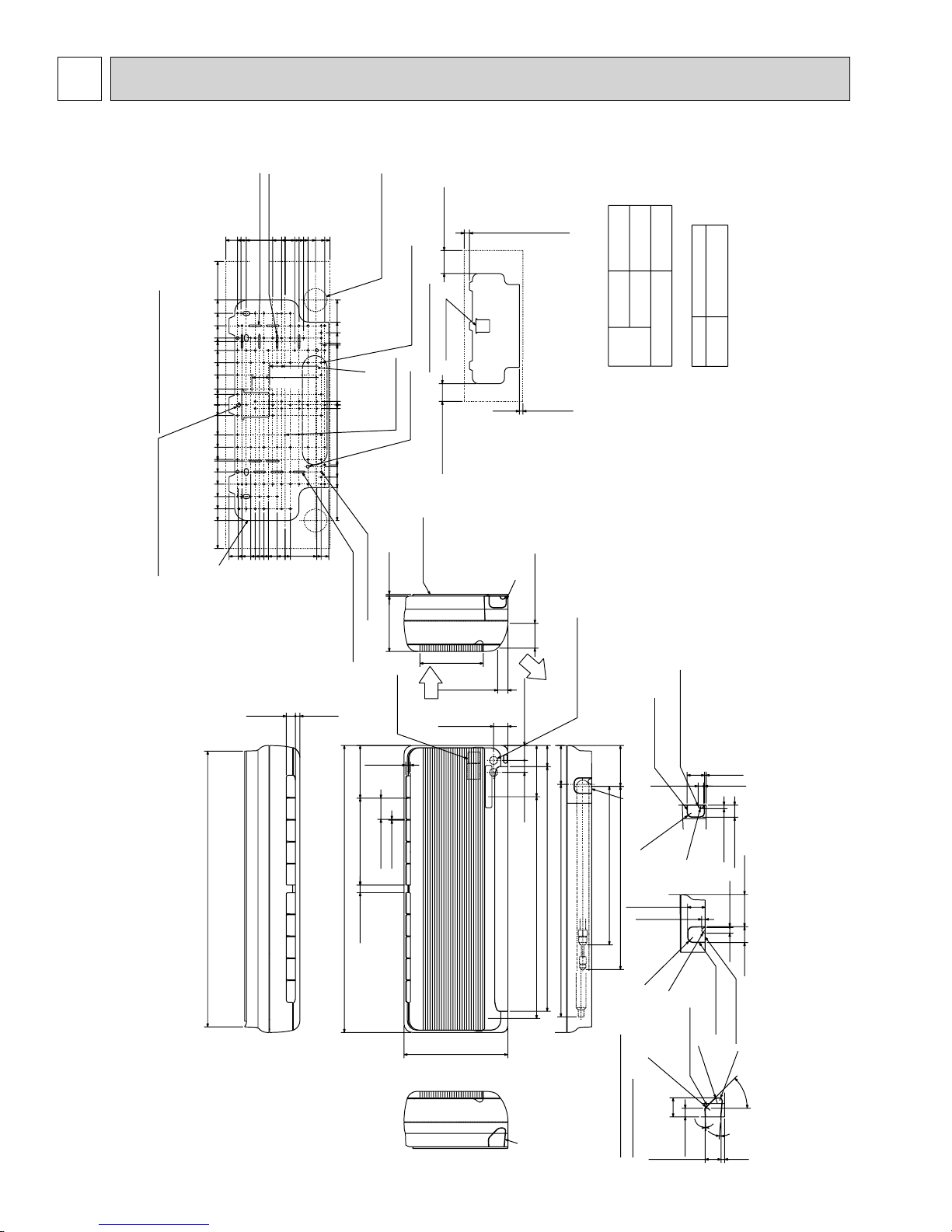
5
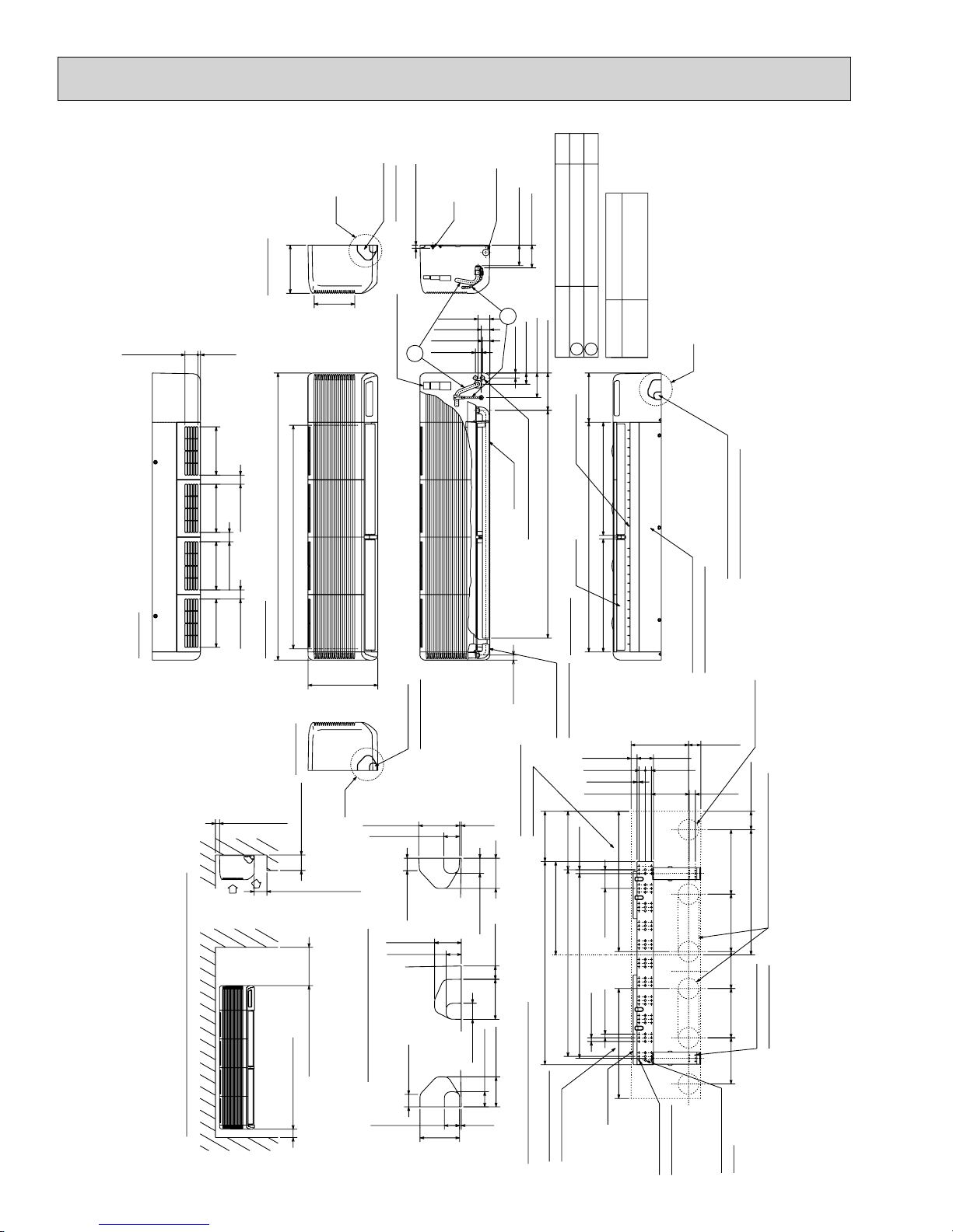
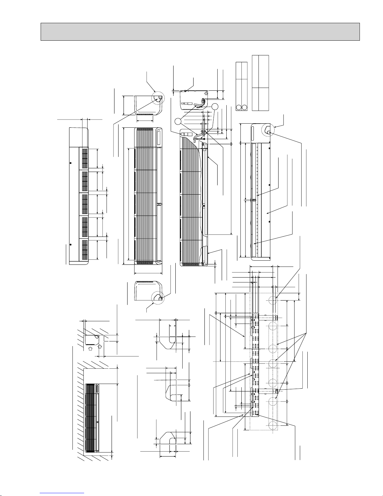
OUTLINES AND DIMENSIONS
PKFY-P06NAMU-E
PKFY-P08NAMU-E
Details of installation plate
Installat plate balance point hole
30-13/16(783)
6-5/8(168)
5-5/16(135)
4-11/32(110)
4-29/32(125)
1-3/8(35)013/32(10)
16-1/32(407.5)
11-23/32(298)
10-1/4(260)
8-27/32(225)
7-15/32(190)
7-3/32(180)
6-3/32(155)
4-23/32(120)
3-11/32(85)
1-3/4(45)
1-3/16(30)
0
0
0
0
1-3/16(30)
3-11/32(85)
4-23/32(120)
6-3/32(155)
6-1/4(159)
7-15/32(190)
8-27/32(225)
10-1/4(260)
11-5/8(295)
12-29/32(328)
16-1/32(407.5)
Installation plate
3/16x1-9/16 (4.5x40) 4 holes
3/16x1-15/32 (4.5x37) 4 holes
2-3/8(60)
5-1/4(133)
6-1/4(159)
1-7/8(47.5)
3-11/32(85)
3-27/32(97.5)
2-27/32(72.5)
4-13/16(122.5)
0
0
0
1-3/32(27.5)
1-9/16(40)
1-23/32(44)
1-31/32(50)
0
0
0
0
0
19/32(15)
7/8(22.5)
Air intake
4-7/16(113)
3-7/16(87)
5-1/32(128)
2-9/16(65)
2-3/32(53)
0
0
0
4-7/8(124)
3-17/32(90)
4-1/32(102.5)
3/16x1-3/8(4.5x35) 4 holes
1/2(13) 1(25.5)
5-29/32(150)
9-3/4(247.5)
32-3/32(815)
27/32(21.5)
Piping hole:2-9/16(:65)
11-23/32(298)
9-1/4(235)
8-1/16(205)
6-7/8(175)
6-11/16(170)
Knockout hole
13/32(10)
13/32(10)
12-:1/8(:2.8)holes
6-11/16(170)
6-7/8(175)
8-1/16(205)
9-1/4(235)
12-29/32 (328)
3/16(5)
8-:5/32(:4.3) holes
6-7/32(158)
Air intake
3/32(2.5)
2-3/8(60)
5-1/8(130) or more
87-:3/16(:5.1)holes
Installation space
4-:11/32(:9)holes
3-15/16(100) or more
installaion plate
Terminal block
(Direction)
Air intake
1/2(13)
Supporting piece
Air intake
7-3/32(180)
Air outlet
1-15/32(37.4)
1-5/8(40.5)
left-rear piping
leftpiping
J1
2-1/8(54) of more
1 5-1/8(130) or more
25/32(20) or more
A
2-25/32(70.3)
Air outlet
Wiring entrance holes
Air outlet
(Direction)
1-11/16(42.5)
5-3/4 (146)
2-3/8 (60)
4-11/32(110)
1-11/ 32(34)
Air outlet
Air intake
27-3/8(695)
(Drain pipe total 29-29/32(760))
24-13/16(630)
26-31/32(660)
Unit : inch(mm)
1/2F
1/4F
:5/8(:16) I.D
Through-hole
:2-9/16~:2-3/4
Liquid pipe
Gas pipe
(:65~:70)
Drain pipe
Sleeve
:2-9/16
piping
Refrigerart
Notes 1. Use M10 or W3/8 screw for installation plate.
2. Extension piping side.
Knockout hole for
remote control wiring
Knockout hole of
right piping
4-9/16(116)
B
A
Gas pipe
R15/32(R12)
Liquid pipe
17-23/32(450)
20-25/32(520)
1-31/32(50)
13/32(10)
(:65)
3. Sleeves are available on the market.
1-31/32 (50)
5/8 (16)
R5/16(R8)
5/32(4)
13/32(10)
1-11/32(34)
3/32(2.5)
3/32(2.5)
3-19/32 (91.5)
B
5/8(16)
R19/32(R15)
R5/16(R8)
1-25/32 (45)
16
11-5/8(295)
Knockout holt for
under piping
Knockout hole of
remote control wiring
Knockout hole for
left piping
R15)
R5/16(R8)
R19/32(R15)
C
2-1/8(54)
C
Detailed figure dwg (ABC)
(Knockout hole)
31/32(24.4)
R19/32(
45
3
5
1-25/32(45)13/32(10)
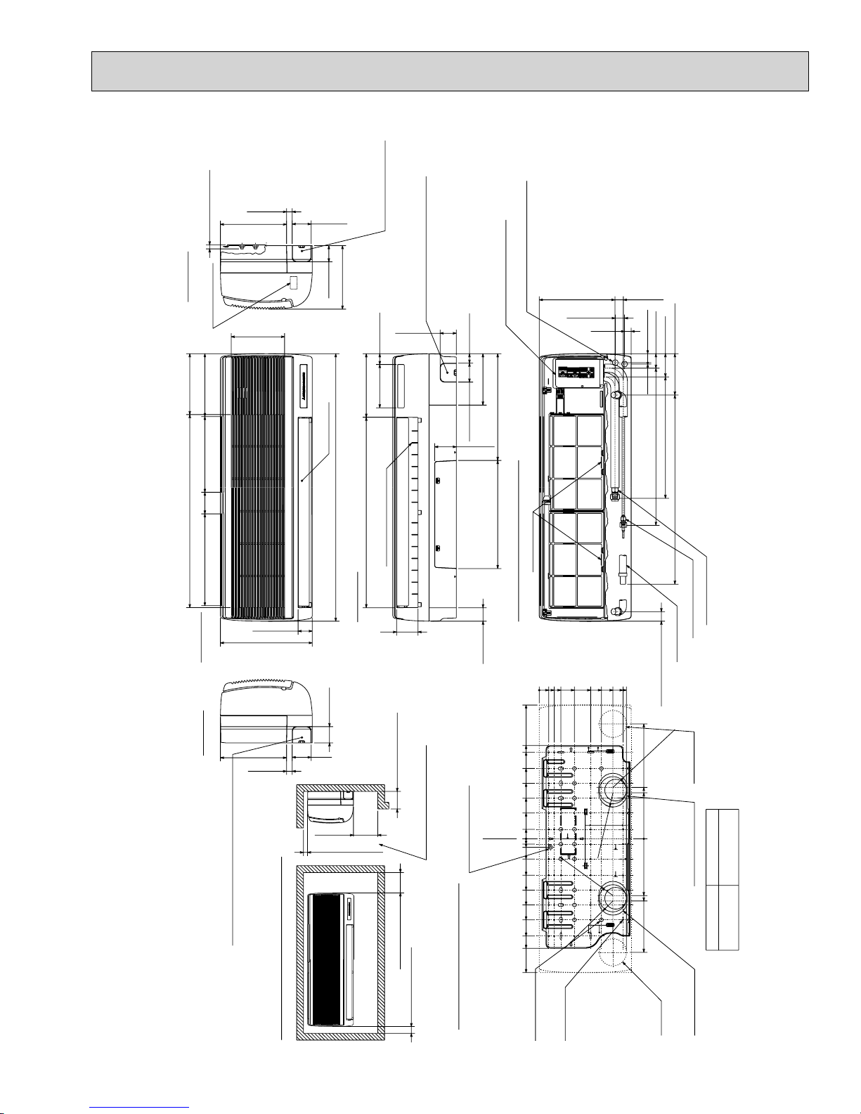
PKFY-P12NGMU-E
PKFY-P15NGMU-E
Unit : inch(mm)
Less than 19/32(15)
Right side
Address board
Air intake
11-1/32(280) 9-3/16(233)
3-5/32(80)
28-5/32(715) Air intake 8-27/32(225)
Air intake
13-3/8(340)
Front view
Left side
Knock out hole for left piping
Refrigerant pipe.Drain pipe.Wiring hole.
13/16(21)
9-21/32(245)
Air intake
7-25/32(198)
2-3/32(53)
13-3/8(340)
9-21/32(245)
13/16(21)
Right side
2-3/4(70)
Knockout hole for right piping
Refrigerant pipe.Drain pipe.
Wiring hole
9-1/4(235)
2-3/8(60)
Knockout hole for under piping
6-5/16(160) 1-9/16(40)
Auto vane
39(990)
27-3/4(705) Air outlet 9-1/4(235)
12—Louvers (manual)
Lower side
2-3/8(60)
2-3/4(70)
Less than 5-1/8(130)
7-3/32(180) or more
1-13/16(30) or more
5-29/32(150) or more
Wiring entrance holes
Refrigerant piping.Drain pipe.
Wiring hole
2-3/8(60)
Service panel
(Power supply access)
7-15/32(190)
15-9/16(395)15-3/4(400)
2-3/4(70) 1-3/8(35)
3-1/8(80)
Front view (top open the grille)
3-1/8(79)
1-31/32(50)
19-1/2(495)
13-19/32(345)
12-19/32(320)
10-1/4(260)
8-1/16(205)
5-29/32(150)
3-3/4(95)
1-3/8(35)
0
25/32(20)
(Necessary clearance for
Unit installation)
Installation plate
balance point hole
Unit center
1-1/4(32)
2-15/16(75)
5-5/16(135)
7-15/32(190)
9-21/32(245)
11-13/16(300)
14-3/16(360)
15-15/16(405)
19-1/2(495)
Filter grip
0
1-3/8(35)
2-5/32(55)
0
3-5/32(80)
5-1/8(130)
R2-1/16(R52.5)
1-11/32(34)
1(25)
7-15/32(190)
9-1/16(230)
10-23/32(272)
16(R52.5)
R2-1/
R2-1/16(R52.5)
1-5/16(33)
3/16(5)
12-11/16(322)+1
12-7/32(310)
(Left side piping
R2-1/16(R52.
0
1-7/32(31) 11-1/32(280)
2-1/8(54)
(Right side piping installation)
3-3/8(86)
17-11/16(449)
22-7/8(581)
27-9/16(700) 6-1/32(153)
(Flexible hose total length 31-1/2(800))
Gas pipe 1/2F
Liquid pipe 1/4F
Drain hose
installation)
1-3/8(35)
16-23/32(425)
5)
Right-rear
piping hole
7-15/32(190)
6-11/16(170)
+1 Sleeves are available on the market.
Through-holeSleeve 1
Knockout hole for
right-rear piping
:2-15/16~:3-5/32
8-9/32(210)
9-1/16(230)
:2-15/16(:75)
16-17/32(420)
+2 This size shows the lower end of through hole.
(:75~:80)
Service space required around indoor unit
1-31/32(50) or more
Details of installation plate
17
14-:9/16(:14)holes
for bolts
for tapping screw
49-:3/16(:5)holes
Left-rear
piping hole
Knockout hole for
left-rear piping
PKFY-P18NFMU-E
PKFY-P24NFMU-E
P24
3/8FLiquid pipe
5/8F
Unit : inch(mm)
Top side
2-15/32(62.5)
9-1/4(235)
9-1/4(235)
9-1/4(235) 9-1/4(235)
1/2(13)
1-25/32(45)
1-25/32(45)
1-25/32(45)
9-1/4(235)
Right side
55-1/8(1400)
42-29/32(1090) Air intake
Front view
C
Knock out hole
7-3/4(197)
13-3/8(340)
for right piping
Less than 19/32(15)
2
Terminal blockTerminal block
Bolt
Drain hose
2-9/32(58)
1-21/32(42)
1-7/16(36)
1-5/16(34)
4-7/32(107)
P18MODEL
4-3/8(111)
1/4F / 3/8F (Compatible)
1
1
2-5/32(55)
15/16(24)
7-7/32(183)
4-23/32(120)
9-7/16(240)
Louvers(Manual)Auto vanes
Drain hose
Wiring entrance holes
44-3/32(1120)
43-11/16(1110) Drain hose
Lower side
31/32(25)
1/2F / 5/8F (Compatible)
:3-17/32~:3-15/16
(:90~:100)
Through-hole
+1
Gas pipe
:3-17/32
21-23/32(552) Air outlet
21-23/32(552) Air outlet
(:90)
Sleeve
+1 Sleeves are available
on the market.
B
2
Under panel(Removable at
Knockout hole for under-piping
Refrigerant pipe /Drain pipe
left-hand side piping)
Left side
1-3/16(30) or more
Less than 9-27/32(250)
Air
intake
Air
outlet
9-27/32(250) or more
1-31/32(50) or more
Service space required around indoor unit
Knockout hole
for left piping
A
3-15/16(100)
1-17/32(39)
9-27/32(250) or more
1-3/16(30)
2-9/16(65)
1-15/32(37)
Knockout hole for wiring
1-3/16(30)
AB C
1-17/32(39)
5/32(4)
2-29/32(74)
1-15/32(37)
1-1/4(32)
3-27/32(98)
1-9/16(39)
2-29/32(74)
1-15/32(37)
5/32(4)
3-15/16(100)
18
Drain hose for
left-hand side piping
1-5/32(29)
1-3/16(30)
13/32(10)
7-1/4(184)
Drainage range on
right-hand side
3/4(19)
9-21/32(245)
17-29/32(455)
Unit center
38-31/32(990)
35-7/16(900)
23/32(18)
13/323-19/32=(35-13/16) (1091=(910)) 11-7/32(285)
3-19/32(91)
23/32(18)
Wall fixture
Drainage range on
left hand side
Details of installation plate
66-:1/4(:6) holes
11-1/32(280)
3-1/8(80)
1-3/16(30)
for tapping screws
2-3/8(60)
1-3/16(30)
11-1/32(280) 12-3/8(314)
7-3/32(180)
9-7/16(240)
8-27/32(225)
32-:15/32(:12) holes
for bolts
Rear piping hole
3-17/32(90)
24-1/32(610)
Range for left rear piping hole
12-1/4(6) holes
for tapping screws
PKFY-P30NFMU-E
Unit : inch(mm)
Top side
2-15/32(62.5)
1/2(13)
9-1/4(235)
1-25/32(45)
9-1/4(235)
9-1/4(235)
9-1/4(235)
1-25/32(45)
9-1/4(235)
9-1/4(235)
Right side
Knock out hole
for right piping
66-1/8(1680)
1-25/32(45)
1-25/32(45)
Front view
53-15/16(1370) Air intake
C
7-3/4(197)
13-3/8(340)
Less than 9/16(15)
2
Terminal block
Knockout hole
for left piping
Bolt
2-9/32(58)
1-21/32(42)
1-7/16(36)
1-5/16(34)
4-3/8(111)
4-1/32(102)
7-7/32(183)
4-23/32(120)
Liquid pipe 3/8F
1
9-7/16(240)
1
2-5/32(55)
15/16(24)
Drain hose
Wiring entrance holes
43-11/16(1110) Drain hose
55-1/8(1400)
Lower side
Drain hose for
left-hand side piping
31/32(25)
5/8F
Gas pipe
2
27-5/16(694) Air outlet
27-5/16(694) Air outlet
1-5/32(29)
1-3/16(30)
13/32(10)
Through-hole
:3-17/32~:3-15/16
(:90~:100)
+1
(:90)
:3-17/32
Sleeve
+1 Sleeves are available
on the market.
Louvers(Manual)
11-1/32(280)
3-5/32(80)
1-3/16(30)
B
Under panel(Removable at
left-hand side piping)
Knockout hole for under-piping
Refrigerant pipe /Drain pipe
Auto vanes
2-3/8(60)
Rear piping hole
1-3/16(30) 7-1/4(184)
3-9/16(90)
Left side
1-3/16(30) or more
Less than 5-29/32(150)
Air
Air
intake
Service space required around indoor unit
outlet
9-27/32(250) or more
1-31/32(50) or more
A
3-15/16(100)
9-27/32(250) or more
1-3/16(30)
2-9/16(65)
1-15/32(37)
ACB
1-3/16(30)
Knockout hole for wiring
5/32(4)
2-29/32(74)
1-15/32(37)
1-1/4(32)
3-27/32(98)
1-17/32(39)
2-29/32(74)
1-15/32(37)
5/32(4) 1-17/32(39)
3-15/16(100)
19
9-21/32(245)
1-17/32(39)
Drainage range on
right-hand side
50(1270)
Unit center
Unit out line
Drainage range on
left hand side
3/4(19)
11-7/32(285)
23-7/16(595)
35-7/16(900)
1/23-19/32=(46-9/16) (1391=(1183))
Wall fixture
84-:1/4(:6) holes
3-19/32(91)
23/32(18)
23/32(18)
for tapping screws
29-17/32(750)
9-7/16(240) 7-3/32(180) 11-1/32(280) 12-3/8(314)
11-5/8(295) 8-27/32(225)
41-:15/32(:12) holes
Range for left rear piping hole
12-:1/4(:6) holes
for tapping screws
for bolts

6
WIRING DIAGRAM
PKFY-P06NAMU-E
PKFY-P08NAMU-E
[ LEGEND ]
SYMBOL NAME NAMESYMBOL SYMBOL
A. B
SWITCH
SW1
SW5
SW11
SW12
SW14
M. B
INDOOR CONTROLLER BOARD
CONNECTOR
CN32
CN51
CN52
SW2
SWITCH
SW3
NAME
MODE SELECTION
VOLTAGE SELECTION
ADDRESS SETTING 1ST DIGIT
ADDRESS SETTING 2ST DIGIT
CONNECTION No.
REMOTE SWITCH
CENTRALLY CONTROL
REMOTE INDICATION
CAPACITY CODE
MODE SELECTION
P. BCIRCUIT BOARD (ADDRESS)
INDOOR POWER BOARD
CAPACITOR (FAN MOTOR)
C
FAN PHASE CONTROL
F.C
FUSE (6A/250V)
FUSE
VARISTOR
ZNR
LEV
MF
MV
TB2
TB5
TH21
TH22
TH23
LINEAR EXPANSION VALVE
FAN MOTOR
VANE MOTOR
TERMINAL
BLOCK
THERMISTOR
POWER SUPPLY
TRANSMISSION
ROOM TEMP. DETECTION
(32°F/15k, 77°F/5.4k)
PIPE TEMP. DETECTION/LIQUID
(32°F/15k, 77°F/5.4k)
PIPE TEMP. DETECTION/GAS
(32°F/15k, 77°F/5.4k)
TH21TH22TH23
A.B
SW5
ON
OFF
12345678910
3RD
DIGIT
230V208V
SW1
SW12 SW14SW11
00
2ND
1ST
DIGIT
DIGIT
5VDC SUPPLY
4
(RED)
3
ADDRESS
2
CN43
1
(RED)
ADDRESS
CN82
0
CONNECTION
NO.
LEV
ORN
WHT
YLW
123456
CN60
LEV
(WHT)
4
8
7
6
5
4
3
2
1
8
OFF
12345678910
1234
12345 12345
CENTRALLY
CONTROL
ON
M.B
6
RED
BLU
CN51
(WHT)
SW3 SW2
BRN
12345
MV
5
YLW
RED
ORN
BLU
CN5V
(
BLU)
CN52
REMOTE
INDICATION
(GRN)
See Fig.1
REMOTE
1234
CN42
ADDRESS
(RED)
LED2
YLW
123 123
CN32
CN34
(GRN
SWITCH
(WHT)
12345678
CN81
ADDRESS
(RED)
POWER BOARD
BRN
GRY
12 12
CN21
CN29
LIQUID
GAS
)
(WHT
(BLK
)
123
CN3A
(BLU)
CN53M
12345
(RED)
CN35M
POWER BOARD
(BLU)
)
INTAKE
123
12
CN20
(RED)
Notes:
1. At servicing for outdoor unit, always follow the wiring diagram of outdoor unit.
2. In case of connecting MA-Remote controller, please connect MA remote controller cable in an accessorie
to the connector . (Remote controller wire is non-polar.)
12
3.In case of using M-NET, please connect to TB5. (Transmission line is non-polar.)
4.Symbols used in wiring diagram above are, : terminal block, : connecter, : direct wire connection.
5.Please set the switch SW5 according to the power supply voltage.
Set SW5 to 230V side when the power supply is 230 volts.
When the power supply is 208 volts, set SW5 to 208V side.
6. The setting of the SW2 dip switches differs in the capacity. For the detail, refer to the Fig.1.
LED on indoor board for service
Mark
LED1
LED2
Meaning Function
Main power supply
Power supply for
MA -Remote controller
Main power supply (Indoor unit:208-230V)
power on © lamp is lit
Power supply for MA -Remote controller
on © lamp is lit
TO MA-REMOTE
CONTROLLER
DC8.7-13V
12
MF
ORN
ORN
YLW
ORN
BRN
123
CN35P
MICON
BOARD
(BLU)
BLK
5
CN53P
YLW
4
MICON
ORN
3
BOARD
RED
2
(RED)
BRN
1
LED1
TO OUTDOOR UNIT
BC CONTROLLER
M-NET REMOTE CONTROLLER
DC24-30V
M2M1
TB5 S(SHIELD)
BLU
BLU
WHT
RED
BLK
12
CN2M
M-NET
(BLU)
F.C
123456 123
(GRN)
FAN
C
ZNR
CND
(RED)
<Fig.1>
MODELS
PKFY-P06NAMU-E
PKFY-P08NAMU-E
<+>Use Copper Supply Wire.
RED
FUSE
250V
6A
TO NEXT
INDOOR UNIT
<+>
TB2
L1
L2
GR
GRN/YLW
BREAKER
BLU
(15A)
POWER SUPPLY
~/N 208-230V 60Hz
P.B
SW2
ON
OFF
1234
ON
OFF
1234
PULL
BOX
FUSE
(15A)
20
 Loading...