

Mitsubishi Electric PEFY-P06, PEFY-P15, PEFY-P08, PEFY-P18l, PEFY-P12 Installation Manual
...Page 1

Air-Conditioners
INDOOR UNIT
PEFY-P06,P08,P12,P15,P18,P24 NMSU-E
GB
INSTALLATION MANUAL
For safe and correct use, please read this installation manual thoroughly before installing the air-conditioner unit.
MANUEL D’INSTALLATION
Veuillez lire le manuel d’installation en entier avant d’installer ce climatiseur pour éviter tout accident et vous assurer d’une utilisation correcte.
F
KB79K383H01_cv.p65 08.1.22, 5:45 PM3
Page 2
3
3.2
[Fig. 3.2.1]
4
4.1
[Fig. 4.1.1]
A Refrigerant pipe (liquid pipe): HP
B Refrigerant pipe (gas pipe): LP
C Drain pipe (O.D. ø32 mm [1-1/4 in])
D Drain pipe (O.D. ø32 mm [1-1/4 in], spontaneous draining)
A Unit body
B Lifting machine
C Nuts (field supply)
D Washers (accessory)
E M10 hanging bolt (field supply)
5
5.2
[Fig. 5.1.1] [Fig. 5.1.2] [Fig. 5.2.1]
5.1
6
6.2
[Fig. 6.2.1]
2
A Center of gravity
A Access door
B Electrical parts box
C Air inlet
D Air outlet
E Ceiling surface
F Service space (viewed from the side)
G Service space (viewed from the direction of arrow)
1 600 mm [23-5/8 in] or more
2 100 mm [3-15/16 in] or more
3 10 mm [13/32 in] or more
4 300 mm [11-13/16 in] or more
A Indoor unit’s bottom surface
YX
LW
A
Z
B
A
A
A
B
C
D
270 [10-21/32]
170
[6-23/32]
102
[4-1/32]
48
[1-29/32]
270 [10-21/32]
116
[4-19/32]70[2-25/32]
B
C
D
A
F
G
3
4
E
A
50~150 [1-31/32~5-29/32] 450 [17-23/32]
450 [17-23/32]
49
[1-15/16]
625
[24-5/8]
777 [30-19/32]
100
[3-15/16]
20
[13/16]
90
[3-9/16]
23
[29/32]
C
B
A
D
B
E
200 [7-7/8]
1
2
C
D
C
E
D
(Unit: mm [in])
Model
PEFY-P06,08,12 NMSU-E
PEFY-P15,18NMSU-E
PEFY-P24NMSU-E
A
700
[27-9/16]
900
[35-7/16]
1100
[43-5/16]
B
752
[29-5/8]
952
[37-1/2]
1152
[45-3/8]
C
798
[31-7/16]
998
[39-5/16]
1198
[47-3/16]
D
660
[26]
860
[33-7/8]
1060
[41-3/4]
E
800
[31-1/2]
1000
[39-3/8]
1200
47-1/4
(Unit: mm [in])
(Unit: mm [in])
KB79K383H01-p02 08.1.16, 2:44 PM2
Page 3
3
A Cut here
B Remove brazed cap
A
A
E
C
F
B
D
A Thermal insulation
B Pull out insulation
C Wrap with damp cloth
D Return to original position
E Ensure that there is no gap here
F Wrap with insulating tape
7
[Fig. 7.1.1]
7.1
[Fig. 7.1.3]
B
J
O
N
F
Max. 300 mm [11-13/16 in]
[Fig. 7.2.1]
Correct piping
Wrong piping
A Insulation (9 mm [3/8 in] or more)
B Downward slope (1/100 or more)
C Support metal
K Air bleeder
L Raised
M Odor trap
Grouped piping
D O. D. ø32 mm [1-1/4 in] PVC TUBE
E Make it as large as possible. About 10 cm [3-15/16 in].
F Indoor unit
G Make the piping size large for grouped piping.
H Downward slope (1/100 or more)
I O. D. ø38 mm [1-1/2 in] PVC TUBE for grouped piping.
(9 mm [3/8 in] or more insulation)
J Up to 550 mm [21-21/32 in]
N Drain hose (accessory)
O Horizontal or slightly upgradient
7.2
[Fig. 7.2.2]
C
B
A
L
D
D
D
E
K
M
B
H
I
Max. 20m [65 ft]
1.5-2 m [5 to 7 ft]
G
F
FF
B
C
DE E
H
G
K
J
F
I
A
25 [1] 25 [1]
35
[1-13/32]
A Indoor unit
B Insulation pipe (long) (accessory)
C Tie band (accessory)
D Visible part
E Insertion margin
F Drain hose (accessory)
G Drain pipe (O.D. ø32 mm [1-1/4 in] PVC TUBE, field supply)
H Insulating material (field supply)
I Tie band (accessory)
J Max.180 ± 5 mm [7-3/32 ± 7/32 in]
K To be gap free. The joint section of the insulation material meet must be
at the top.
A
[Fig. 7.1.2]
A Cool by a wet cloth
[Fig. 7.2.3]
A Indoor unit
B Insulation pipe (short) (accessory)
C Tie band (accessory)
D Band fixing part
E Insertion margin
F Drain hose (accessory)
G Drain pipe (O.D. ø32 mm [1-1/4 in] PVC TUBE, field supply)
H Insulating material (field supply)
I Max.145 ± 5 mm [5-23/32 ± 7/32 in]
D
E
H
G
I
F
B
C
5
[7/32]
A
25 [1]
(Unit: mm [in])
(Unit: mm [in])
KB79K383H01-illust 08.1.16, 2:44 PM3
Page 4
4
A Air inlet
B Air outlet
C Access door
D Ceiling surface
E Canvas duct
F Air filter
G Inlet grille
AB
DE
CCCCCCC
8
[Fig. 8.0.1]
9
9.1
[Fig. 9.1.1] [Fig. 9.2.1]
[Fig. 9.2.2]
TB5 TB5
SM1M2 SM1M2
TB3
M1M2
AA
B
CC
TB5 TB15 TB5 TB15
SM1M2 SM1M2
TB3
M1M2 21 21
AA
B
CC
F
G
E
DC
BA
A Switch 16 A
B Overcurrent protection 16 A
C Indoor unit
D Total operating current be less than 16 A
E Pull box
A Terminal block for indoor
transmission cable
B Terminal block for outdoor
transmission cable
C Remote controller
A Non-polarized
B TB15
C Remote Controller
D TB5
[Fig. 9.2.3] [Fig. 9.2.4]
2
S
M2
M1
A
B
D
1
DC10~13V
AB
12
L1
L2
G
C
D
A
S
M2
M1
B
1
2
L1
L2
G
DC24~30V
(A, B)
12
C
9.2
[Fig. 7.3.1]
7.3
A
B
F
C
D
E
A Insert pump's end 2 to 4 cm [13/16 to 1-19/32 in].
B Remove the water supply port.
C About 2000 cc
D Water
E Filling port
F Screw
[Fig. 7.3.2]
SWE
<Indoor board>
KB79K383H01-illust 08.1.16, 2:44 PM4
Page 5
5
E Use conduit to keep the weight of the cable and external force from being applied
to the power supply terminal connector.
F Power source wiring
G Conduit
H Terminal bed box
I Knockout hole (for power source wiring)
J Washer (accessory)
K Tensile force
L Use ordinary bushing
M Transmission wiring
N Power source terminal bed
O Terminal bed for indoor transmission
P Terminal bed for remote controller
Q To 1-phase power source
R Transmission line DC 30 V
S Terminal bed for outdoor transmission line (TB3)
T Transmission line to the remote controller, ter minal bed for indoor unit and
BC controller
A Terminal bed
B Round terminal
C Shield wire
D The ground wire from two cables are connected together to the S terminal. (Dead-end connection)
E Insulation tape (To keep the ground wire of the shielded cable from coming in contact with the transmis-
sion terminal)
<Address board>
9.3
[Fig. 9.3.3] [Fig. 9.3.4]
[Fig. 9.5.1]
[Fig. 9.3.5]
9.5
A Terminal bed box
B Knockout hole
C RemoveA Screw holding cover (2pcs)
B Cover
[Fig. 9.3.1] [Fig. 9.3.2]
A
B
C
A
B
M2
M1
O
N
T
P
R
S
M1 M2 S
12
L1
L2 G
Q
L2
L1
E
F
G
K
M
L
J
H
G
I
M2 SM1
A
B
C
E
D
A
C
FD BE
2
1
A SWA
B SWC
C SW1
D SW11
E SW12
F SW14
KB79K383H01-illust 08.1.16, 2:45 PM5
Page 6
6
GBDFEINLPGRRUTR
CZSVHGPO
Contents
1. Safety precautions
1.1. Before installation and electric work
s Before installing the unit, make sure you read all the “Safety
precautions”.
s The “Safety precautions” provide very important points re-
garding safety. Make sure you follow them.
Symbols used in the text
Warning:
Describes precautions that should be observed to prevent danger of injury
or death to the user.
Caution:
Describes precautions that should be observed to prevent damage to the
unit.
Symbols used in the illustrations
: Indicates an action that must be avoided.
: Indicates that important instructions must be followed.
: Indicates a part which must be grounded.
: Indicates that caution should be taken with rotating parts. (This symbol is
displayed on the main unit label.) <Color: Yellow>
: Beware of electric shock. (This symbol is displayed on the main unit label.)
<Color: Yellow>
Warning:
Carefully read the labels affixed to the main unit.
Warning:
• Ask the dealer or an authorized technician to install the air conditioner.
- Improper installation by the user may result in water leakage, electric shock,
or fire.
• Install the air unit at a place that can withstand its weight.
- Inadequate strength may cause the unit to fall down, resulting in injuries.
• Use the specified cables for wiring. Make the connections securely so
that the outside force of the cable is not applied to the terminals.
- Inadequate connection and fastening may generate heat and cause a fire.
• Prepare for typhoons and other strong winds and earthquakes and install the unit at the specified place.
- Improper installation may cause the unit to topple and result in injury.
• Always use an air cleaner, humidifier, electric heater, and other accessories specified by Mitsubishi Electric.
- Ask an authorized technician to install the accessories. Improper installation
by the user may result in water leakage, electric shock, or fire.
• Never repair the unit. If the air conditioner must be repaired, consult the
dealer.
- If the unit is repaired improperly, water leakage, electric shock, or fire may
result.
• Do not touch the heat exchanger fins.
- Improper handling may result in injury.
• When handling this product, always wear protective equipment.
EG: Gloves, full arm protection namely boiler suit, and safety glasses.
- Improper handling may result in injury.
• If refrigerant gas leaks during installation work, ventilate the room.
- If the refrigerant gas comes into contact with a flame, poisonous gases will
be released.
• Install the air conditioner according to this Installation Manual.
- If the unit is installed improperly, water leakage, electric shock, or fire may
result.
• Have all electric work done by a licensed electrician according to “Electric Facility Engineering Standard” and “Interior Wire Regulations”and
the instructions given in this manual and always use a special circuit.
- If the power source capacity is inadequate or electric work is performed im-
properly, electric shock and fire may result.
• Keep the electric parts away from water (washing water etc.).
- It might result in electric shock, catching fire or smoke.
• Securely install the outdoor unit terminal cover (panel).
- If the terminal cover (panel) is not installed properly, dust or water may enter
the outdoor unit and fire or electric shock may result.
• When installing and moving the air conditioner to another site, do not
charge it with a refrigerant different from the refrigerant specified on the
unit.
- If a different refrigerant or air is mixed with the original refrigerant, the refrig-
erant cycle may malfunction and the unit may be damaged.
• If the air conditioner is installed in a small room, measures must be taken
to prevent the refrigerant concentration from exceeding the safety limit
even if the refrigerant should leak.
- Consult the dealer regarding the appropriate measures to prevent the safety
limit from being exceeded. Should the refrigerant leak and cause the safety
limit to be exceeded, hazards due to lack of oxygen in the room could result.
• When moving and reinstalling the air conditioner, consult the dealer or
an authorized technician.
- If the air conditioner is installed improperly, water leakage, electric shock, or
fire may result.
• After completing installation work, make sure that refrigerant gas is not
leaking.
- If the refrigerant gas leaks and is exposed to a fan heater, stove, oven, or
other heat source, it may generate noxious gases.
• Do not reconstruct or change the settings of the protection devices.
- If the pressure switch, thermal switch, or other protection device is shorted
and operated forcibly, or par ts other than those specified by Mitsubishi Electric are used, fire or explosion may result.
• To dispose of this product, consult your dealer.
• Do not use a leak detection additive.
1.2. Precautions for devices that use R410A
or R22 refrigerant
Caution:
• Do not use the existing refrigerant piping.
- The old refrigerant and refrigerator oil in the existing piping contains a large
amount of chlorine which may cause the refrigerator oil of the new unit to
deteriorate.
• Use refrigerant piping made of C1220 (Cu-DHP) phosphorus deoxidized
copper as specified in the JIS H3300 “Copper and copper alloy seamless
pipes and tubes”. In addition, be sure that the inner and outer surfaces of
the pipes are clean and free of hazardous sulphur, oxides, dust/dirt, shaving particles, oils, moisture, or any other contaminant.
- Contaminants on the inside of the refrigerant piping may cause the refriger-
ant residual oil to deteriorate.
• Store the piping to be used during installation indoors and keep both
ends of the piping sealed until just before brazing. (Store elbows and
other joints in a plastic bag.)
- If dust, dirt, or water enters the refrigerant cycle, deterioration of the oil and
compressor trouble may result.
1. Safety precautions ...................................................................................... 6
1.1. Before installation and electric work .......................................... 6
1.2. Precautions for devices that use R410A
or R22 refrigerant ...................................................................... 6
1.3. Before getting installed .............................................................. 7
1.4. Before getting installed (moved) - electrical work ...................... 7
1.5. Before starting the test run ........................................................ 7
2. Indoor unit accessories ............................................................................... 7
3. Selecting an installation site ....................................................................... 7
3.1. Install the indoor unit on a ceiling strong enough to sustain
its weight ................................................................................... 8
3.2. Securing installation and service space .................................... 8
3.3. Combining indoor units with outdoor units ................................ 8
4. Fixing hanging bolts .................................................................................... 8
4.1 Fixing hanging bolts .................................................................. 8
5. Installing the unit ......................................................................................... 8
5.1. Hanging the unit body ............................................................... 8
5.2. Confirming the unit’s position and fixing hanging bolts ............. 8
6. Refrigerant pipe and drain pipe specifications ............................................ 8
6.1. Refrigerant pipe and drain pipe specifications .......................... 9
6.2. Refrigerant pipe, drain pipe ....................................................... 9
7. Connecting refrigerant pipes and drain pipes ............................................. 9
7.1. Refrigerant piping work ............................................................. 9
7.2. Drain piping work ....................................................................... 9
7.3. Confirming drain discharge ..................................................... 10
8. Duct work .................................................................................................. 10
9. Electrical wiring ......................................................................................... 10
9.1. Power supply wiring................................................................. 11
9.2. Connecting remote controller, indoor and outdoor
transmission cables ................................................................. 11
9.3. Connecting electrical connections ........................................... 11
9.4. External I/O specifications ....................................................... 12
9.5. Selecting the external static pressure ..................................... 12
9.6. Setting addresses .................................................................... 12
9.7. Sensing room temperature with the built-in sensor in
a remote controller .................................................................. 12
KB79K383H01_en 08.1.16, 2:45 PM6
Page 7
7
GBDFEINLPGRRUTRCZSVHGPO
• Use ester oil, ether oil or alkylbenzene (small amount) as the refrigerator
oil to coat flares and flange connections.
- The refrigerator oil will degrade if it is mixed with a large amount of mineral oil.
• Use liquid refrigerant to fill the system.
- If gas refrigerant is used to seal the system, the composition of the refriger-
ant in the cylinder will change and performance may drop.
• Do not use a refrigerant other than R410A or R22.
- If another refrigerant is used, the chlorine in the refrigerant and the refriger-
ant oil in the existing piping may cause the refrigerator oil to deteriorate.
• Use a vacuum pump with a reverse flow check valve.
- The vacuum pump oil may flow back into the refrigerant cycle and cause the
refrigerator oil to deteriorate.
• Do not use the following tools that are used with conventional refrigerants.
(Gauge manifold, charge hose, gas leak detector, reverse flow check valve,
refrigerant charge base, vacuum gauge, refrigerant recovery equipment)
- If the conventional refrigerant and refrigerator oil are mixed in the R410A or
R22, the refrigerant may deteriorated.
- If water is mixed in the R410A or R22, the refrigerator oil may deteriorate.
- Since R410A does not contain any chlorine, gas leak detectors for conven-
tional refrigerants will not react to it.
• Do not use a charging cylinder.
- Using a charging cylinder may cause the refrigerant to deteriorate.
• Be especially careful when managing the tools.
- If dust, dirt, or water gets in the refrigerant cycle, the refrigerant may deterio-
rate.
1.3. Before getting installed
Caution:
• Do not install the unit where combustible gas may leak.
- If the gas leaks and accumulates around the unit, an explosion may result.
• Do not use the air conditioner where food, pets, plants, precision instruments, or artwork are kept.
- The quality of the food, etc. may deter iorate.
• Do not use the air conditioner in special environments.
- Oil, steam, sulfuric smoke, etc. can significantly reduce the performance of
the air conditioner or damage its parts.
• When installing the unit in a hospital, communication station, or similar
place, provide sufficient protection against noise.
- The inverter equipment, private power generator, high-frequency medical
equipment, or radio communication equipment may cause the air conditioner
to operate erroneously, or fail to operate. On the other hand, the air conditioner may affect such equipment by creating noise that disturbs medical
treatment or image broadcasting.
• Do not install the unit on a structure that may cause leakage.
- When the room humidity exceeds 80 % or when the drain pipe is clogged,
condensation may drip from the indoor unit. Perform collective drainage work
together with the outdoor unit, as required.
• The indoor models should be installed the ceiling over than 2.5 m [9 ft]
from floor.
1.4. Before getting installed (moved) - elec-
trical work
Caution:
• Ground the unit.
- Do not connect the ground wire to gas or water pipes, lightning rods, or
telephone ground lines. Improper grounding may result in electric shock.
• Install the power cable so that tension is not applied to the cable.
- Tension may cause the cable to break and generate heat and cause a fire.
• Install an leak circuit breaker, as required.
- If an leak circuit breaker is not installed, electric shock may result.
• Use power line cables of sufficient current carrying capacity and rating.
- Cables that are too small may leak, generate heat, and cause a fire.
• Use only a circuit breaker and fuse of the specified capacity.
- A fuse or circuit breaker of a larger capacity or a steel or copper wire may
result in a general unit failure or fire.
• Do not wash the air conditioner units.
- Washing them may cause an electric shock.
• Be careful that the installation base is not damaged by long use.
- If the damage is left uncorrected, the unit may fall and cause personal injury
or property damage.
• Install the drain piping according to this Installation Manual to ensure
proper drainage. Wrap thermal insulation around the pipes to prevent
condensation.
- Improper drain piping may cause water leakage and damage to furniture
and other possessions.
• Be very careful about product transportation.
- Only one person should not carry the product if it weighs more than 20 kg
[45 LBS].
- Some products use PP bands for packaging. Do not use any PP bands for a
means of transportation. It is dangerous.
- Do not touch the heat exchanger fins. Doing so may cut your fingers.
- When transporting the outdoor unit, suspend it at the specified positions on
the unit base. Also support the outdoor unit at four points so that it cannot
slip sideways.
• Safely dispose of the packing materials.
- Packing materials, such as nails and other metal or wooden parts, may cause
stabs or other injuries.
- Tear apart and throw away plastic packaging bags so that children will not
play with them. If children play with a plastic bag which was not tor n apart,
they face the risk of suffocation.
1.5. Before starting the test run
Caution:
• Turn on the power at least 12 hours before starting operation.
- Starting operation immediately after turning on the main power switch can
result in severe damage to internal parts. Keep the power switch turned on
during the operational season.
• Do not touch the switches with wet fingers.
- Touching a switch with wet fingers can cause electric shock.
• Do not touch the refrigerant pipes during and immediately after operation.
- During and immediately after operation, the refrigerant pipes are may be hot
and may be cold, depending on the condition of the refrigerant flowing through
the refrigerant piping, compressor, and other refrigerant cycle parts. Your
hands may suffer burns or frostbite if you touch the refrigerant pipes.
• Do not operate the air conditioner with the panels and guards removed.
- Rotating, hot, or high-voltage parts can cause injuries.
• Do not turn off the power immediately after stopping operation.
- Always wait at least five minutes before tur ning off the power. Otherwise,
water leakage and trouble may occur.
2. Indoor unit accessories
The unit is provided with the following accessories:
3. Selecting an installation site
• Select a site with sturdy fixed surface sufficiently durable against the weight of
unit.
• Before installing unit, the routing to carry in unit to the installation site should
be determined.
• Select a site where the unit is not affected by entering air.
• Select a site where the flow of supply and return air is not blocked.
• Select a site where refrigerant piping can easily be led to the outside.
• Select a site which allows the supply air to be distributed fully in room.
• Do not install unit at a site with oil splashing or steam in much quantity.
• Do not install unit at a site where combustible gas may generate, flow in, stagnate or leak.
• Do not install unit at a site where equipment generating high frequency waves
(a high frequency wave welder for example) is provided.
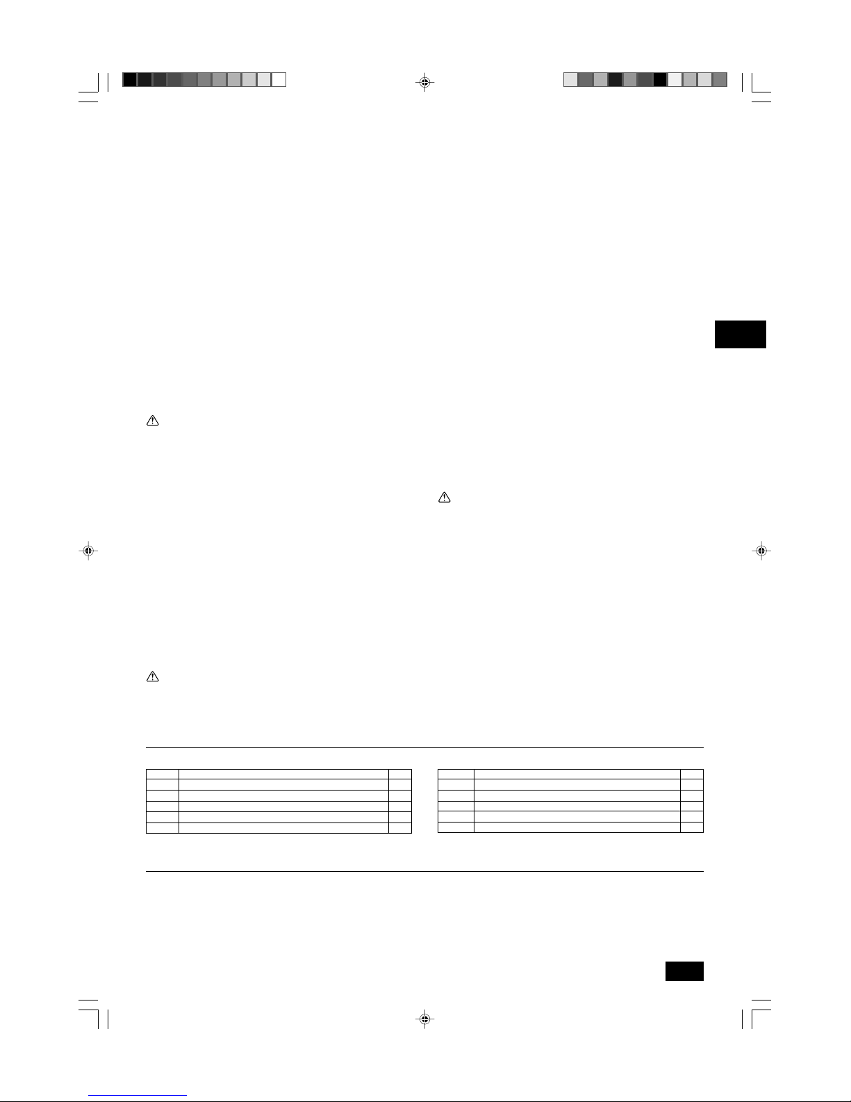
Part No. Accessories Qty
1 Insulation pipe (long) 1
2 Insulation pipe (short) 1
3 Tie band 3
4 Drain hose 1
5 Washer (for hanging) 8
Part No. Accessories Qty
6
Short pipe (ø12.7 mm [1/2 in]-ø15.88 mm [5/8 in]) : Model P18 only.
1
7
Short pipe (ø6.35 mm [1/4 in]-ø9.52 mm [3/8 in]) : Model P18 only.
1
8 Installation manual 1
9 Operation manual 1
10 Washer (for power source wiring) 2
KB79K383H01_en 08.1.24, 10:33 AM7
Page 8
8
GBDFEINLPGRRUTR
CZSVHGPO
4. Fixing hanging bolts
4.1 Fixing hanging bolts
[Fig. 4.1.1] (P.2)
A Center of gravity
(Give site of suspension strong structure.)
Hanging structure
• Ceiling: The ceiling structure varies from building to one another. For detailed
information, consult your construction company.
• Do not install unit at a site where fire detector is located at the supply air side.
(Fire detector may operate erroneously due to the heated air supplied during
heating operation.)
• When special chemical product may scatter around such as site chemical plants
and hospitals, full investigation is required before installing unit. (The plastic
components may be damaged depending on the chemical product applied.)
• If the unit is run for long hours when the air above the ceiling is at high temperature/high humidity (due point above 26 °C [79 °F]), due condensation may
be produced in the indoor unit. When operating the units in this condition, add
insulation material (10 - 20 mm [13/32 to 13/16 in]) to the entire surface of the
indoor unit to avoid due condensation.
3.1. Install the indoor unit on a ceiling strong
enough to sustain its weight
Warning:
The unit must be securely installed on a structure that can sustain its weight.
If the unit is mounted on an unstable structure, it may fall down causing
injuries.
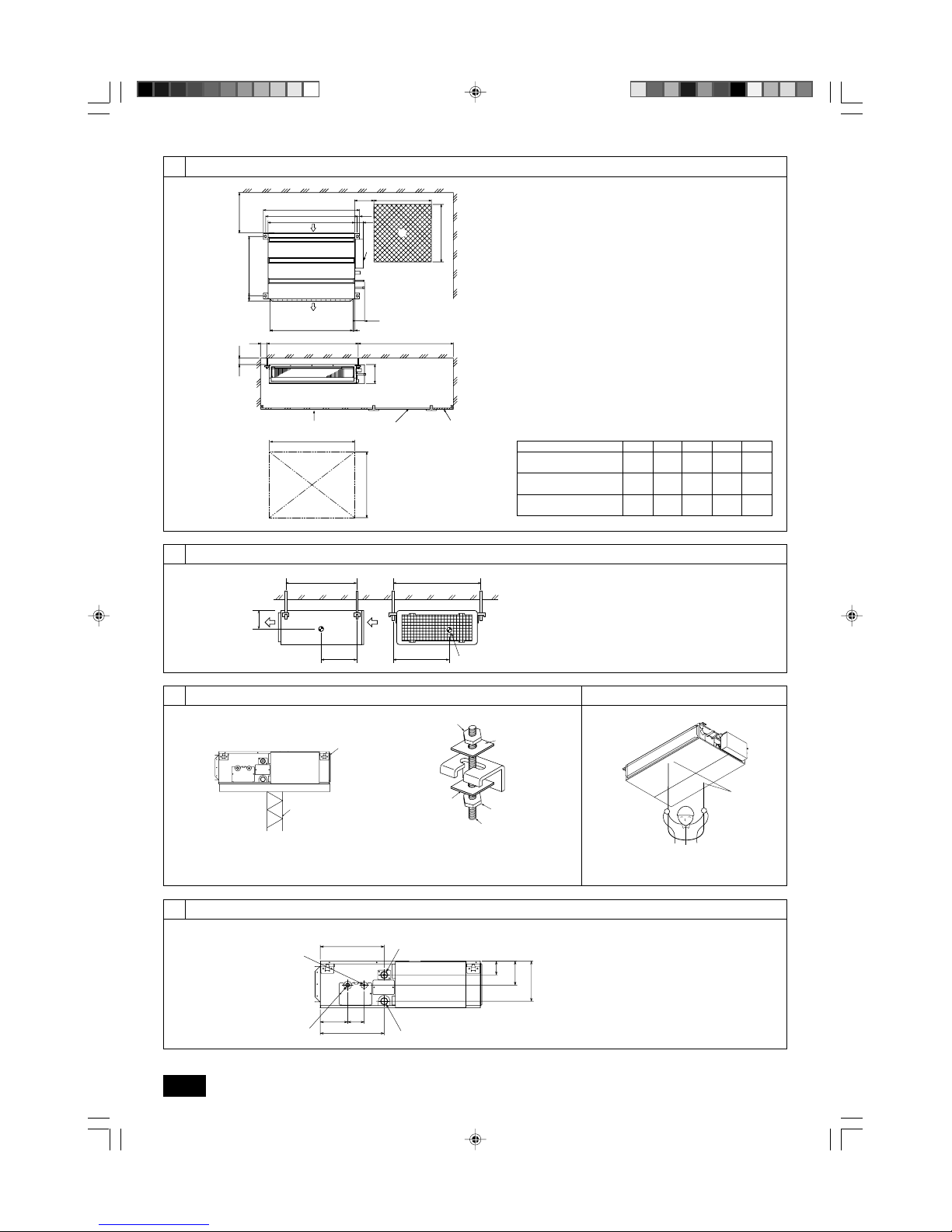
3.2. Securing installation and service space
• Select the optimum direction of supply airflow according to the configuration of
the room and the installation position.
• As the piping and wiring are connected at the bottom and side surfaces, and
the maintenance is made at the same surfaces, allow a proper space properly.
For the efficient suspension work and safety, provide a space as much as
possible.
[Fig. 3.2.1] (P.2)
A Access door B Electrical parts box
C Air inlet D Air outlet
E Ceiling surface F Service space (viewed from the side)
G Service space (viewed from the direction of arrow)
1 600 mm [23-5/8 in] or more 2 100 mm [3-15/16 in] or more
3 10 mm [13/32 in] or more 4 300 mm [11-13/16 in] or more
3.3. Combining indoor units with outdoor
units
For combining indoor units with outdoor units, refer to the outdoor unit installation
manual.
• If necessary, reinforce the hanging bolts with anti-quake supporting members
as countermeasures against earthquakes.
* Use M10 for hanging bolts and anti-quake supporting members (field supply).
5. Installing the unit
5.1. Hanging the unit body
ss
ss
s Bring the indoor unit to an installation site as it is packed.
ss
ss
s To hang the indoor unit, use a lifting machine to lift and pass through the
hanging bolts.
[Fig. 5.1.1] (P.2)
A Unit body
B Lifting machine
[Fig. 5.1.2] (P.2)
C Nuts (field supply)
D Washers (accessory)
E M10 hanging bolt (field supply)
5.2. Confirming the unit’s position and fix-
ing hanging bolts
ss
ss
s Use the gage supplied with the panel to confirm that the unit body and
hanging bolts are positioned in place. If they are not positioned in place,
it may result in dew drops due to wind leak. Be sure to check the positional
relationship.
ss
ss
s Use a level to check that the surface indicated by
AA
AA
A is at level. Ensure
that the hanging bolt nuts are tightened to fix the hanging bolts.
ss
ss
s To ensure that drain is discharged, be sure to hang the unit at level using
a level.
[Fig. 5.2.1] (P.2)
A Indoor unit’s bottom surface
Caution:
Install the unit in horizontal position. If the side with drain port is installed
higher, water leakage may be caused.
6. Refrigerant pipe and drain pipe specifications
Model name
PEFY-P06NMSU-E
PEFY-P08NMSU-E
PEFY-P12NMSU-E
PEFY-P15NMSU-E
PEFY-P18NMSU-E
PEFY-P24NMSU-E
W (mm [in])
625 [24-5/8]
625 [24-5/8]
625 [24-5/8]
625 [24-5/8]
625 [24-5/8]
625 [24-5/8]
L (mm [in])
752 [29-5/8]
752 [29-5/8]
752 [29-5/8]
952 [37-1/2]
952 [37-1/2]
1152 [45-3/8]
X (mm [in])
263 [10-3/8]
263 [10-3/8]
275 [10-27/32]
280 [11-1/32]
280 [11-1/32]
285 [11-1/4]
Y (mm [in])
338 [13-5/16]
338 [13-5/16]
340 [13-13/32]
422 [16-5/8]
422 [16-5/8]
511 [20-1/8]
Z (mm [in])
105 [4-5/32]
105 [4-5/32]
104 [4-1/8]
104 [4-1/8]
104 [4-1/8]
104 [4-1/8]
Product Weight (kg [Ib])
19 [42]
19 [42]
20 [46]
24 [54]
24 [54]
28 [62]
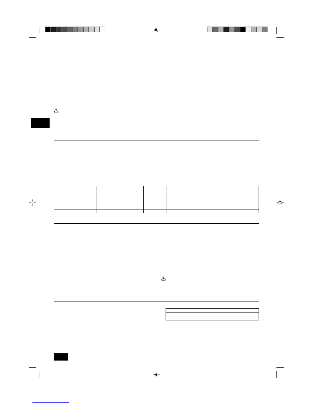
Center of gravity and Product Weight
To avoid dew drops, provide sufficient antisweating and insulating work to the refrigerant and drain pipes.
When using commercially available refrigerant pipes, be sure to wind commercially available insulating material (with a heat-resisting temperature of more than
100 °C [212 °F]and thickness given below) onto both liquid and gas pipes.
Insulate all indoor pipes with form polyethylene insulation with a minimum density
of 0.03 and a thickness as specified in the table below.
1 Select the thickness of insulating material by pipe size.
2 If the unit is used on the highest story of a building and under conditions of
high temperature and humidity, it is necessary to use pipe size and insulating
material’s thickness more than those given in the table above.
3 If there are customer’s specifications, simply follow them.
Insulating material’s thickness
More than 10 mm [13/32 in]
More than 15 mm [19/32 in]
Pipe size
6.4 to 25.4 mm [1/4 to 1 in]
28.6 to 38.1 mm [1-1/8 to 1-1/2 in]
KB79K383H01_en 08.1.24, 10:33 AM8
Page 9

9
GBDFEINLPGRRUTRCZSVHGPO
• Store the piping to be used during installation indoors and keep both
ends of the piping sealed until just before brazing.
- If dust, dirt, or water gets into the refrigerant cycle, the oil will deteriorate and
the compressor may fail.
• Use Suniso 4GS or 3GS (small amount) refrigerator oil to coat the flare
and flange connection part. (For models using R22)
•
Use ester oil, ether oil or alkylbenzene (small amount) as the refrigerator oil
to coat flares and flange connections. (For models using R410A)
- The refrigerant used in the unit is highly hygroscopic and mixes with water
and will degrade the refrigerator oil.
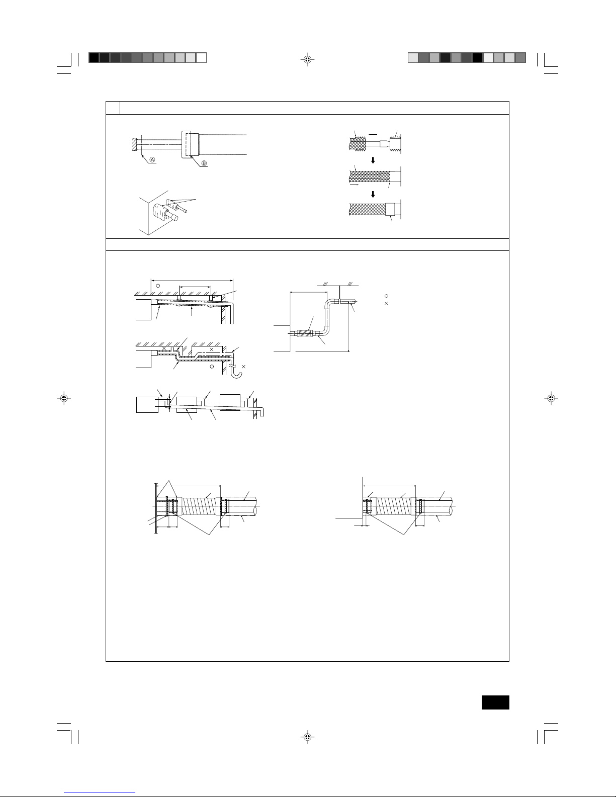
7.2. Drain piping work
• Ensure that the drain piping is downward (pitch of more than 1/100) to the
outdoor (discharge) side. Do not provide any trap or irregularity on the way.
• Ensure that any cross-wise drain piping is less than 20 m [65 ft] (excluding the
difference of elevation). If the drain piping is long, provide metal braces to prevent
it from waving. Never provide any air vent pipe. Otherwise drain may be ejected.
• Use a hard vinyl chloride pipe O.D. ø32 mm [1-1/4 in] for drain piping.
• Ensure that collected pipes are 10 cm [3-15/16 in] lower than the unit body’s
drain port.
• Do not provide any odor trap at the drain discharge port.
• Put the end of the drain piping in a position where no odor is generated.
•
Do not put the end of the drain piping in any drain where ionic gases are generated.
[Fig. 7.2.1] (P.3)
Correct piping
Wrong piping
A Insulation (9 mm [3/8 in] or more)
B Downward slope (1/100 or more)
C Support metal
K Air bleeder
L Raised
M Odor trap
Grouped piping
D O. D. ø32 mm [1-1/4 in] PVC TUBE
E Make it as large as possible. About 10 cm [3-15/16 in].
F Indoor unit
G Make the piping size large for grouped piping.
H Downward slope (1/100 or more)
I O. D. ø38 mm [1-1/2 in] PVC TUBE for grouped piping.
(9 mm [3/8 in] or more insulation)
J Up to 550 mm [21-21/32 in]
N Drain hose (accessory)
O Horizontal or slightly upgradient
1. Insert the drain hose (accessory) into the drain port (inser tion margin: 25 mm
[1 in]).
(The drain hose must not be bent more than 45° to prevent the hose from
breaking or clogging.)
(Attach the hose with glue for the hard vinyl chloride pipe, and fix it with the
band (small, accessory).)
2. Attach the drain pipe (O.D. ø32 mm [1-1/4 in] PVC TUBE, field supply).
(Attach the pipe with glue for the hard vinyl chloride pipe, and fix it with the
band (small, accessory).)
3. Perform insulation work on the drain pipe (O.D. ø32 mm [1-1/4 in] PVC TUBE)
and on the socket (including elbow).
7. Connecting refrigerant pipes and drain pipes
7.1. Refrigerant piping work
This piping work must be done in accordance with the installation manuals for both
outdoor unit and BC controller (simultaneous cooling and heating series R2).
• Series R2 is designed to operate in a system that the refrigerant pipe from an
outdoor unit is received by BC controller and branches at the BC controller to
connect between indoor units.
• For constraints on pipe length and allowable difference of elevation, refer to
the outdoor unit manual.
• The method of pipe connection is brazing connection.
Caution:
• Install the refrigerant piping for the indoor unit in accordance with the
following.
1. Cut the tip of the indoor unit piping, remove the gas, and then remove the
brazed cap.
[Fig. 7.1.1] (P.3)
A Cut here
B Remove brazed cap
2. Pull out the thermal insulation on the site refrigerant piping, braze the unit
piping, and replace the insulation in its original position.
Wrap the piping with insulating tape.
Note:
• When blazing the refrigerant pipes, be sure to blaze, after covering a wet
cloth to the pipes of the units in order to prevent it from burning and
shrinking by heat.
[Fig. 7.1.2] (P.3)
A Cool by a wet cloth
• Pay strict attention when wrapping the copper piping since wrapping the
piping may cause condensation instead of preventing it.
[Fig. 7.1.3] (P.3)
A Thermal insulation B Pull out insulation
C Wrap with damp cloth D Return to original position
E Ensure that there is no gap here F Wrap with insulating tape
Cautions On Refrigerant Piping
ss
ss
s Be sure to use non-oxidative brazing for brazing to ensure that no for-
eign matter or moisture enter into the pipe.
ss
ss
s Be sure to apply refrigerating machine oil over the flare connection seat-
ing surface and tighten the connection using a double spanner.
ss
ss
s Provide a metal brace to support the refrigerant pipe so that no load is
imparted to the indoor unit end pipe. This metal brace should be provided 50 cm [19-11/16 in] away from the indoor unit’s flare connection.
Warning:
When installing and moving the unit, do not charge it with refrigerant other
than the refrigerant specified on the unit.
- Mixing of a different refrigerant, air, etc. may cause the refrigerant cycle to mal-
function and result in severe damage.
Caution:
• Use refrigerant piping made of C1220 (Cu-DHP) phosphorus deoxidized
copper as specified in the JIS H3300 “Copper and copper alloy seamless
pipes and tubes”. In addition, be sure that the inner and outer surfaces of
the pipes are clean and free of hazardous sulphur, oxides, dust/dirt, shaving particles, oils, moisture, or any other contaminant.
• Never use existing refrigerant piping.
- The large amount of chlorine in conventional refrigerant and refrigerator oil
in the existing piping will cause the new refrigerant to deteriorate.
6.1. Refrigerant pipe and drain pipe specifications
Refrigerant pipe
(Brazing connection)
Model R410A R22
Item 06·08·12·15·18 24 06·08·12·15 18·24*
Liquid pipe ø 6.35 [1/4] ø 9.52 [3/8] ø 6.35 [1/4] ø 9.52 [3/8]
Gas pipe ø 12.7 [1/2] ø 15.88 [5/8] ø 12.7 [1/2] ø 15.88 [5/8]
Drain pipe O.D. ø 32 [1-1/4] O.D. ø 32 [1-1/4]
6.2. Refrigerant pipe, drain pipe
[Fig. 6.2.1] (P.2)
A Refrigerant pipe (liquid pipe): HP
B Refrigerant pipe (gas pipe): LP
C Drain pipe (O.D. ø32 mm [1-1/4 in])
D Drain pipe (O.D. ø32 mm [1-1/4 in], spontaneous draining)
* When the Models P18 are used with R22, use the supplied short pipes.
(Unit: mm [in])
KB79K383H01_en 08.1.28, 2:26 PM9
Page 10

10
GBDFEINLPGRRUTR
CZSVHGPO
9. Electrical wiring
Precautions on electrical wiring
Warning:
Electrical work should be done by qualified electrical engineers in accordance with “Engineering Standards For Electrical Installation” and supplied
installation manuals. Special circuits should also be used. If the power circuit lacks capacity or has an installation failure, it may cause a risk of electric shock or fire.
1. Be sure to install an earth leakage breaker to the power.
2. Install the unit to prevent that any of the control circuit cables (remote controller, transmission cables) is brought in direct contact with the power cable outside the unit.
3. Ensure that there is no slack on all wire connections.
4. Some cables (power, remote controller, transmission cables) above the ceiling
may be bitten by mouses. Use as many metal pipes as possible to insert the
cables into them for protection.
5. Never connect the power cable to leads for the transmission cables. Otherwise
the cables would be broken.
6. Be sure to connect control cables to the indoor unit, remote controller, and the
outdoor unit.
7. Put the unit to the ground on the outdoor unit side.
8. Select control cables from the conditions given in page
11
.
Caution:
Be sure to put the unit to the ground on the outdoor unit side. Do not connect the ground cable to any gas pipe, water pipe, lightening rod, or telephone
ground cable. Incomplete grounding may cause a risk of electric shock.
Types of control cables
1. Wiring transmission cables
• Types of transmission cables
Design wiring in accordance with the following table <Table 1>.
• Cable diameter
More than 1.25 mm
2
[AWG16]
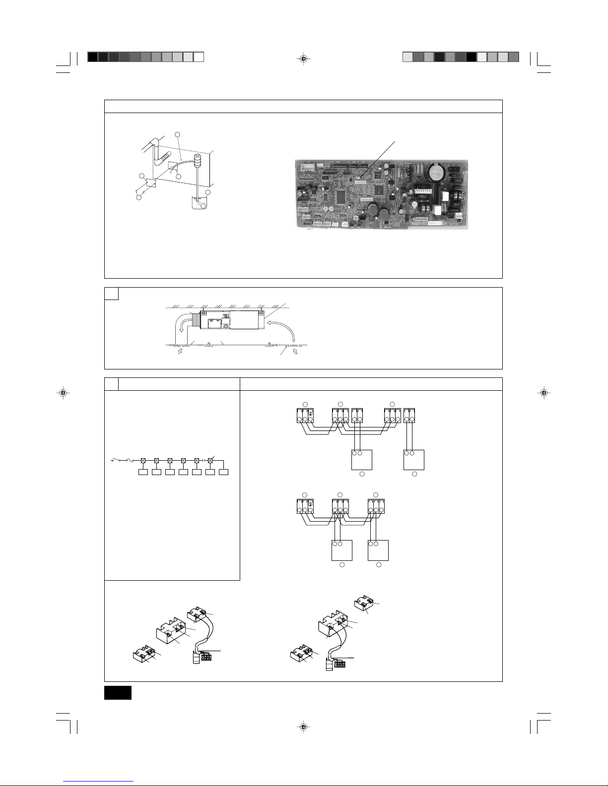
8. Duct work
• When connecting ducts, insert a canvas duct between the main body and the
duct.
• Use non-combustible duct components.
• Install sufficient thermal insulation to prevent condensation forming on outlet
duct flanges and outlet ducts.
Caution:
• Keep the distance between the inlet grille and the fan over 850 mm
[33-15/32 in].
If it is less than 850 mm [33-15/32 in], install a safety guard not to touch
the fan.
[Fig. 8.0.1] (P.4)
A Air inlet B Air outlet
C Access door D Ceiling surface
E Canvas duct F Air filter
G Inlet grille
1. Remove the water supply port cover on the same side as the indoor unit piping.
2. Fill water into the feed water pump using a feed water tank. In filling, be sure to
put the end of the pump or tank in a drain pan. (If the insertion is incomplete,
water may flow over the machine.)
3. Perform the test run in cooling mode, or turn on the switch SWE on the controller circuit board. (The drain pump and the fan are forced to operate without any
remote controller operation.) Make sure using a transparent hose that drain is
discharged.
4. After confirmation, cancel the test run mode, and turn off the main power.
When
the switch SWE has been turned on, turn it off, and attach the water supply
port cover into its original position.
[Fig. 7.3.1] (P.4)
A Insert pump's end 2 to 4 cm [13/16 to 1-19/32 in].
B Remove the water supply port.
C About 2000 cc
D Water
E Filling port
F Screw
[Fig. 7.3.2] (P.4)
<Indoor board>
4. Check the drainage. (Refer to [Fig. 7.3.1])
5. Attach the insulating material (accessory), and fix it with the band (large, accessory) to insulate the drain port.
[Fig. 7.2.2] (P.3)
A Indoor unit
B Insulation pipe (long) (accessory)
C Tie band (accessory)
D Visible part
E Insertion margin
F Drain hose (accessory)
G Drain pipe (O.D. ø32 mm [1-1/4 in] PVC TUBE, field supply)
H Insulating material (field supply)
I Tie band (accessory)
J Max.180 ± 5 mm [7-3/32 ± 7/32 in]
K To be gap free. The joint section of the insulation material meet must be at the
top.
7.3. Confirming drain discharge
ss
ss
s Make sure that the drain-up mechanism operates normally for discharge
and that there is no water leakage from the connections.
• Be sure to confirm the above in a period of heating operation.
• Be sure to confirm the above before ceiling work is done in the case of a new
construction.
SWE SWE
OFF ON OFF ON
SWE SWE
OFF ON OFF ON
KB79K383H01_en 08.1.16, 2:45 PM10
Page 11

11
GBDFEINLPGRRUTRCZSVHGPO
Caution:
Install wiring so that it is not tight and under tension. Wiring under tension
may break, or overheat and burn.
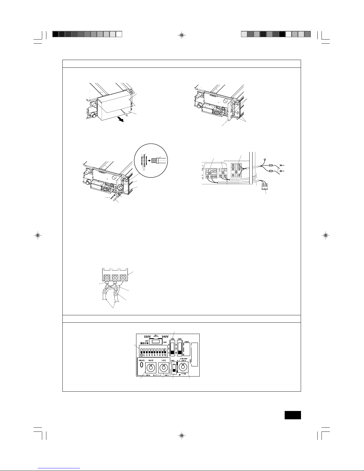
9.3. Connecting electrical connections
Please identify the model name of the operation manual attached on the terminal
bed box cover with that shown on the rating name plate.
1. Remove the screw (2pcs) holding the cover to dismount the cover.
[Fig. 9.3.1] (P.5)
A Screw holding cover (2pcs) B Cover
2. Open knockout holes
(Recommend to use a screwdriver or the like for this work.)
[Fig. 9.3.2] (P.5)
A Terminal bed box B Knockout hole
C Remove
3. Fix power source wiring to terminal bed box by using buffer bushing for tensile
force. (Conduit or the like.) Connect transmission wir ing to transmission terminal bed through the knockout hole of terminal bed box using ordinary bushing.
[Fig. 9.3.3] (P.5)
E Use conduit to keep the weight of the cable and external force from being applied
to the power supply terminal connector.
F Power source wiring G Conduit
H Terminal bed box
I Knockout hole (for power source wiring)
J Washer (accessory) K Tensile force
L Use ordinary bushing M Transmission wiring
4. Connect the power source, Ground, transmission and remote controller wiring.
The dismounting of the terminal bed box is not needed.
[Fig. 9.3.4] (P.5)
N Power source terminal bed O Terminal bed for indoor transmission
P Terminal bed for remote controller Q To 1-phase power source
R Transmission line DC 30 V
S Terminal bed for outdoor transmission line (TB3)
T Transmission line to the remote controller, ter minal bed for indoor unit and BC
controller
[Shield wire connection]
[Fig. 9.3.5] (P.5)
A Terminal bed B Round terminal
C Shield wire
D The ground wire from two cables are connected together to the S terminal. (Dead-
end connection)
E Insulation tape (To keep the ground wire of the shielded cable from coming in
contact with the transmission terminal)
5. After wiring is complete, make sure again that there is no slack on the connections, and attach the cover onto the terminal bed box in the reverse order of
removal.
Notes:
• Do not pinch the cables or wires when attaching the terminal bed box
cover. Doing so may cause a risk of disconnection.
• When accommodating the terminal bed box, make sure that the connectors on the box side are not removed. If removed, it cannot operate normally.
9.1. Power supply wiring
• Power supply cords of appliances shall not be lighter than design 245 IEC 57
or 227 IEC 57.
• A switch with at least 3 mm [1/8 in] contact separation in each pole shall be
provided by the Air conditioner installation.
Power cable size: more than 1.5 mm
2
[AWG16]
[Fig. 9.1.1] (P.4)
A Switch 16 A B Overcurrent protection 16 A
C Indoor unit
D Total operating current be less than 16 A
E Pull box
[Selecting non-fuse breaker (NF) or earth leakage breaker (NV)]
To select NF or NV instead of a combination of Class B fuse with switch, use the
following:
• In the case of Class B fuse rated 15 A or 20 A,
NF model name (MITSUBISHI): NF30-CS (15 A) (20 A)
NV model name (MITSUBISHI): NV30-CA (15 A) (20 A)
Use an earth leakage breaker with a sensitivity of less than 30 mA 0.1 s.
Caution:
Do not use anything other than the correct capacity breaker and fuse. Using
fuse, wire or copper wire with too large capacity may cause a risk of malfunction or fire.
9.2. Connecting remote controller, indoor
and outdoor transmission cables
• Connect indoor unit TB5 and outdoor unit TB3. (Non-polarized 2-wire)
The “S” on indoor unit TB5 is a shielding wire connection. For specifications
about the connecting cables, refer to the outdoor unit installation manual.
• Install a remote controller following the manual supplied with the remote controller.
• Connect the “1” and “2” on indoor unit TB15 to a MA remote controller. (Non-
polarized 2-wire)
• Connect the “M1” and “M2” on indoor unit TB5 to a M-NET remote controller.
(Non-polarized 2-wire)
• Connect the remote controller’s transmission cable within 10 m [32 ft] using a
0.75 mm2 [AWG18] core cable. If the distance is more than 10 m [32 ft], use a
1.25 mm
2
[AWG16] junction cable.
[Fig. 9.2.1] (P.4) MA Remote controller
[Fig. 9.2.2] (P.4) M-NET Remote controller
A Terminal block for indoor transmission cable
B Terminal block for outdoor transmission cable
C Remote controller
• DC 9 to 13 V between 1 and 2 (MA remote controller)
• DC 24 to 30 V between M1 and M2 (M-NET remote controller)
[Fig. 9.2.3] (P.4) MA Remote controller
[Fig. 9.2.4] (P.4) M-NET Remote controller
A Non-polarized B TB15
C Remote Controller D TB5
• The MA remote controller and the M-NET remote controller cannot be used at
the same time or interchangeably.
2. Remote controller cables
Types of cables
Cable diameter
Length
MA remote controller
Sheathed 2-core cable (unshielded) CVV
0.3 to 1.25 mm
2
[AWG22 to 16]
Less than 200 m
M-NET remote controller
Sheathed 2-core cable (unshielded) CVV
0.3 to 1.25 mm
2
[AWG22 to 16]
Add any portion in excess of 10 m [32 ft] to within the longest allowable transmission cable length 200 m [656 ft] (Shielding portion is more than 1.25 mm
2
[AWG16])
<Table 1>
System configuration For a single-refrigerant system For a multi-refrigerant system
Transmission cable length Less than 120 m [394 ft]
More than 120 m [394 ft]
Regardless of length
Facility example
(for noise judgment)
Types of transmission
cables
Residence or independent store
without noise
VCTF, VCTFK, CVV, CVS, VVR,
VVF, VCT or shielding wire
CVVS or CPEVS
Building, clinic, hospital or communications
station without noise supposedly generated
from inverter equipment, private power generator, high-frequency medical equipment,
radio-used communications equipment and
so on
All facilities
Shielding wire CVVS or CPEVS
Length Less than 120 m [394 ft] Less than 200 m [656 ft]
[656 ft]
KB79K383H01_en 08.1.16, 2:45 PM11
Page 12

12
GBDFEINLPGRRUTR
CZSVHGPO
[Fig. 9.5.1] (P.5)
<Address board>
A SWA B SWC
C SW1 D SW11
E SW12 F SW14
9.6. Setting addresses
(Be sure to operate with the main power turned OFF.)
[Fig. 9.5.1] (P.5)
<Address board>
A SWA B SWC
C SW1 D SW11
E SW12 F SW14
• There are two types of rotary switch setting available: setting addresses 1 to 9
and over 10, and setting branch numbers.
1 How to set addresses
Example: If Address is “3”, remain SW12 (for over 10) at “0”, and match
SW11(for 1 to 9) with “3”.
2 How to set branch numbers SW14 (Ser ies R2 only)
The branch number assigned to each indoor unit is the port number of the
BC controller to which the indoor unit is connected.
Leave it to “0” on the non-R2 series of units.
• The rotary switches are all set to “0” when shipped from the factor y. These
switches can be used to set unit addresses and branch numbers at will.
• The determination of indoor unit addresses varies with the system at site. Set
them referring to the Data Book.
9.7. Sensing room temperature with the
built-in sensor in a remote controller
If you want to sense room temperature with the built-in sensor in a remote controller, set SW1-1 on the control board to “ON”. The setting of SW1-7 and SW1-8 as
necessary also makes it possible to adjust the air flow at a time when the heating
thermometer is OFF.
Note:
• To perform the auto cooling/heating operation, use the built-in sensor in
a remote controller or the optional remote sensor.
9.4. External I/O specifications
Caution:
1. Wiring should be covered by insulation tube with supplementary insulation.
2. Use relays or switches with IEC or equivalent standard.
3. The electric strength between accessible parts and control circuit should
have 2750 V or more.
9.5. Selecting the external static pressure
As the factory setting is for use under an external static pressure of 0.06 in. WG
(15 Pa), no switch operation is needed when using under the standard condition.
External static pressure Switch operation
0.02 in. WG
(5 Pa)
0.06 in. WG
(15 Pa)
0.14 in. WG
(35 Pa)
0.20 in. WG
(50 Pa)
3
2
1
SWA
3
2
1
SWA
3
2
1
SWA
3
2
1
SWA
SWC
1
2
SWC
1
2
SWC
1
2
SWC
1
2
KB79K383H01_en 08.1.17, 5:42 PM12
Page 13

13
GB
EINLPGRRUTRCZSVHGPO
F
Table des matières
1. Consignes de sécurité
1.1. Avant l’installation de l’appareil et l’installation électrique
s Avant d’installer le climatiseur, lire attentivement toutes les
“Consignes de sécurité”.
s Les “Consignes de sécurité” reprennent des points très im-
portants concernant la sécurité. Veillez bien à les suivre.
Symboles utilisés dans le texte
Avertissement:
Précautions à suivre pour éviter tout danger de blessure ou de décès de
l’utilisateur.
Précaution:
Précautions à suivre pour éviter tout endommagement de l’appareil.
Symboles utilisés dans les illustrations
: Indique une action qui doit être évitée.
: Indique des instructions importantes à suivre.
: Indique un élément à mettre à la terre.
: Indique la nécessité de faire attention aux pièces tournantes. (Ce symbole
se trouve sur l’étiquette de l’appareil principal.) <Couleur: jaune>
: Danger d’électrocuition. (Ce symbole se trouve sur l’étiquette de l’appareil
principal.) <Couleur: jaune>
Avertissement:
Lisez soigneusement les étiquettes se trouvant sur l’appareil
principal.
Avertissement:
• Demandez à votre revendeur ou à un technicien agréé d’installer le climati-
seur.
- En cas de mauvaise installation, il y aurait un risque de fuite d’eau, d’électrocution ou d’incendie.
• Installez l’appareil sur une structure capable de supporter son poids.
- Autrement l’appareil risque de tomber et de blesser quelqu’un.
• Utilisez les câbles mentionnées pour les raccordements. Assurez-vous que
les connexions soient effectués correctement de façon à ce que la force
externe du câble ne s’applique pas aux bornes.
- Un mauvais raccordement pourrait provoquer une surchauffe, voire un incendie.
• Prenez toutes les mesures nécessaires pour parer aux éventuels typhons
ou autres vents forts ainsi que les tremblements de terre, et installez l’appareil à l’endroit spécifié.
- L’appareil pourrait tomber et par conséquent blesser quelqu’un si l’installation
n’est pas effectuée correctement.
• Utilisez toujours les filtres à air, déshumidificateurs, chauffages électriques
et autres accessoires indiqués par Mitsubishi Electric.
- Demandez à un technicien agréé d’installer les accessoires. Une mauvaise ins-
tallation par l’utilisateur pourrait provoquer des fuites d’eau, électrocution ou un
incendie.
• Ne réparez jamais vous-même l’appareil. En cas de réparation nécessaire,
veuillez consulter le revendeur.
- Toute mauvaise réparation pourrait résulter en des fuites d’eau, chocs électriques ou incendies.
• Ne touchez jamais les ailettes de l’échangeur de chaleur.
- Vous risqueriez de vous blesser.
• Toujours revêtir des vêtements de protection pour manipuler ce produit.
Par ex.: Gants, protection intégrale des bras par combinaison et lunettes
de sécurité.
- Vous risqueriez de vous blesser.
• En cas de fuite de gaz durant l’installation, aérez la pièce.
- Si le gaz réfrigérant entre en contact avec une flamme, il y aura émission de gaz
toxiques.
• Installez le climatiseur en respectant les instructions du manuel d’installation.
- En cas d’installation incorrecte, il y aura un risque de fuites d’eau, d’électrocu-
tion ou d’incendie.
• Demandez à un électricien qualifié d’effectuer l’installation électrique conformément aux “Normes concernant les installations électriques” et les “Réglementations sur le câblage intérieur” ainsi que les instructions de ce manuel; utilisez toujours un circuit différent.
- Si la capacité de la source d’alimentation n’est pas adéquate ou si l’installation
électrique n’est pas effectuée correctement, il y aura un risque d’électrocution
ou d’incendie.
• Maintenez les pièces électriques à l’abri de l’eau (eau de lavage etc.).
- Sinon une électrocution, un incendie ou de la fumée pourrait en résulter.
• Mettez fermement en place le couvercle des bornes de l’appareil extérieur
(panneau).
- Si le couvercle des bornes (panneau) n’est pas mis en place correctement, il se
peut que de la poussière ou de l’eau s’infiltre dans l’appareil extérieur et par
conséquent il y aura un risque d’incendie ou d’électrocution.
• Lors du déplacement et de l’installation du climatiseur à un endroit différent, ne le remplissez pas d’un réfrigérant différent, utilisez le réfrigérant
spécifié sur l’appareil.
- Lorsqu’un réfrigérant différent est mélangé au réfrigérant d’origine, il se peut
que le cycle du réfrigérant ne fonctionne pas correctement et que l’appareil soit
endommagé.
• Si le climatiseur est installé dans une pièce relativement petite, certaines
mesures doivent être prises pour éviter que la concentration de réfrigérant
ne dépasse le seuil de sécurité en tenant compte des possibilités de fuites
de réfrigérant.
- Consultez votre revendeur sur les précautions nécessaires à prendre afin que la
limite admissible ne soit pas dépassée. Si le réfrigérant fuit et que la limite admissible est dépassée, il pourrait se produire des accidents suite au manque
d’oxygène dans la pièce.
• Veuillez consulter votre revendeur ou un technicien agréé lors du déplacement et de l’installation du climatiseur dans un différent endroit.
- Une mauvaise installation du climatiseur pourrait résulter en fuites d’eau, élec-
trocution ou un incendie.
• L’installation terminée, assurez-vous qu’il n’y a aucune fuite de gaz.
- Si le gaz réfrigérant fuit et entre en contact avec un radiateur soufflant, un poêle,
un four ou toute autre source de chaleur, il se peut que des gaz toxiques soient
relâchés.
• Ne réarrangez pas et ne changez pas les réglages des dispositifs de sécurité.
- Si l’interrupteur de pression, l’interrupteur thermique ou tout autre dispositif de
sécurité sont court-circuités ou utilisés avec trop de force, ou si toutes autres
pièces que celles spécifiées par Mitsubishi Electric sont utilisées, il y aura un
risque d’incendie ou d’explosion.
1. Consignes de sécurité .............................................................................. 13
1.1. Avant l’installation de l’appareil et l’installation électrique ....... 13
1.2. Précautions à prendre avec les dispositifs utilisant le
réfrigérant R410A ou R22 ....................................................... 14
1.3. Avant de procéder à l’installation ............................................. 14
1.4. Avant de procéder à l’installation (déplacement)-installation
électrique ................................................................................. 14
1.5. Avant d’effectuer l’essai ........................................................... 14
2. Eléments qui accompagnent l’appareil intérieur ....................................... 15
3. Comment choisir le lieu d’installation ........................................................ 15
3.1. Fixer l’appareil intérieur à un plafond suffisamment résistant
pour supporter son poids ........................................................ 15
3.2. Prévoir l’espace nécessaire pour l’installation et l’entretien .... 15
3.3. Association des appareils intérieurs et des appareils
extérieurs ................................................................................. 15
4. Fixation des boulons de suspension ......................................................... 15
4.1. Fixation des boulons de suspension ....................................... 15
5. Installation de l’appareil ............................................................................ 16
5.1. Suspension de l’appareil ......................................................... 16
5.2. Assurer l’emplacement de l’appareil et fixer les boulons de
suspension .............................................................................. 16
6. Spécifications techniques des tuyaux de réfrigérant et du tuyau
d’écoulement ............................................................................................ 16
6.1. Spécifications techniques des tuyaux de réfrigérant et
d’écoulement ........................................................................... 16
6.2. Tuyau de réfrigérant, tuyau d’écoulement ............................... 16
7. Raccordement des tuyaux de réfrigérant et d’écoulement ....................... 16
7.1. Mise en place des tuyaux de réfrigérant ................................. 16
7.2. Travaux de mise en place du tuyau d’écoulement ................... 17
7.3. Confirmation des décharges d’écoulement ............................. 18
8. Raccords des conduites ........................................................................... 18
9. Câblage électrique .................................................................................... 18
9.1. Câblage de l’alimentation électrique ....................................... 19
9.2. Raccordement des câbles de la commande à distance et
des câbles de transmission intérieurs et extérieurs ................ 19
9.3. Connexions électriques ........................................................... 19
9.4. Spécifications I/O externes ...................................................... 20
9.5. Sélection de la pression statique extérieure ............................ 20
9.6. Configuration des adresses ..................................................... 20
9.7. Détection de la température ambiante à l’aide du capteur
intégré de la commande à distance ........................................ 20
KB79H130H01_F 08.1.24, 10:34 AM13
Page 14

14
GB
EINLPGRRUTR
CZSVHGPO
D
F
• Demandez conseil à votre revendeur avant de mettre le produit aux rebuts.
• N’utilisez pas d’additif de détection des fuites.
1.2. Précautions à prendre avec les dispositifs utilisant le réfrigérant R410A ou
R22
Précaution:
• N’utilisez pas les tuyaux de réfrigérant actuels.
- Le vieux réfr igérant et l’huile réfrigérante se trouvant dans les tuyaux contiennent une large quantité de chlore qui pourrait abîmer l’huile réfrigérante
du nouvel appareil.
• Utilisez des tuyaux réfrigérants en cuivre désoxydé au phosphore C1220
(Cu-DHP) comme l’indique le chapitre “Tuyaux et tubes en cuivre ou en
alliage de cuivre sans soudure” du JIS H3300. Veillez également à ce que
les surfaces internes et externes des tuyaux soient propres et sans soufre, oxyde, poussière/impuretés, rognures, huile, condensation ou autre
particule contaminante.
- Tout contaminant à l’intérieur des tuyaux de réfrigérant pourrait provoquer la
détérioration de l’huile réfrigérante résiduelle.
• Gardez les tuyaux à l’intérieur de l’immeuble et gardez les deux extrémités du tuyau couvertes jusqu’à ce que vous soyez prêt à les braser. (Gardez les joints articulés et autres joints dans des sacs en plastique.)
- Si de la poussière, de la saleté ou de l’eau s’infiltre dans le cycle du réfrigé-
rant, le réfrigérant risque de se détériorer et le compresseur risque de ne
pas fonctionner correctement.
• Appliquez une petite quantité d’huile ester, ether ou alkylbenzène sur les
évasements et les connexions à brides.
- L’huile réfrigérante se détériorera lorsque mélangée à une grande quantité
d’huile minérale.
• Utilisez un réfrigérant liquide pour remplir le système.
- Si l’on utilise du gaz réfr igérant pour rendre le système hermétique, la com-
position du réfrigérant se trouvant dans le cylindre changera et il se peut que
la performance ne soit plus aussi bonne.
• N’utilisez pas un réfrigérant autre que R410A ou R22.
- Si un autre réfr igérant est utilisé, le chlore dans le réfrigérant et l’huile de
réfrigérant dans le tuyau existant peut entraîner une détérioration de l’huile
de réfrigérant.
• Utilisez une pompe à vide équipée d’une valve de contrôle de flux inverse.
- Il se peut que l’huile de la pompe à vide repar te dans le cycle du réfrigérant
ce qui entraînerait la détérioration de l’huile réfrigérante.
• N’utilisez pas les outils énumérés ci-dessous, destinés aux réfrigérants
traditionnels.
(Jauge collectrice, tuyau de charge, détecteur de fuite de gaz, valve de
contrôle de flux inverse, base de remplissage du réfrigérant, jauge à vide,
équipements de récupération de réfrigérant).
- Si le réfr igérant conventionnel et l’huile réfrigérante sont mélangés dans le
R410A ou R22, le réfrigérant peut se détériorer.
- Si de l’eau est mélangée dans le R410A ou R22, l’huile réfrigérante peut se
détériorer.
- Comme les R410A ne contiennent pas de chlore, les détecteurs de fuite de
gaz conventionnels ne réagiront pas sur eux.
• N’utilisez pas de cylindre de charge.
- Autrement le réfrigérant pourrait se détériorer.
• Faites particulièrement attention lors de l’utilisation des outils.
- Si de la poussière, de la saleté ou de l’eau s’infiltre dans le cycle du réfrigé-
rant, il se peut que le réfrigérant se détériore.
1.3. Avant de procéder à l’installation
Précaution:
• N’installez pas l’appareil dans un endroit sujet aux fuites de gas inflammables.
- S’il y a une fuite de gaz et que le gaz s’accumule autour de l’appareil, il y
aura des risques d’explosion.
• N’utilisez pas le climatiseur près d’animaux ou de plantes ou près d’aliments, d’instruments de précision ou d’objets d’art.
- La qualité d’aliments etc. pourrait en souffrir.
• N’utilisez pas le climatiseur dans certains environnements.
- L’huile, la vapeur, la fumée sulfur ique, etc. peuvent considérablement ré-
duire la performance du climatiseur ou en endommager les pièces.
• Lors de l’installation de l’appareil dans un hôpital, une station de communications ou tout endroit similaire, veillez à ce qu’il soit correctement
protégé contre le bruit.
- Les équipements onduleurs, générateurs privés, équipements médicaux à
haute fréquence ou de communication radiophonique peuvent empêcher le
climatiseur de fonctionner ou de fonctionner proprement. De plus, il se peut
que le climatiseur ait un effet nuisible sur ce genre d’équipements en faisant
du bruit qui gênerait les traitements médicaux ou l’envoi d’images.
• N’installez pas l’appareil sur une structure qui pourrait causer des fuites.
- Lorsque l’humidité de la pièce dépasse 80 % ou lorsque le tuyau d’écoule-
ment est bouché, il se peut que des gouttes d’eau tombent de l’appareil
intérieur. Veillez à fournir une voie d’écoulement pour l’appareil intérieur et
l’appareil extérieur si nécessaire.
• Les modèles intérieurs doivent être installés à un plafond situé à plus de
2,5 m [9 ft] du sol.
1.4. Avant de procéder à l’installation (dé-
placement)-installation électrique
Précaution:
• Mettez l’appareil à la terre.
- Ne branchez pas le fil de mise à la terre à un tuyau de gaz ou d’eau, un
paratonnerre ou câble téléphonique de terre. Une mauvaise mise à la terre
peut provoquer des risques d’électrocution.
• Installez le câble d’alimentation de façon à ce qu’il ne soit pas tendu.
- Autrement le fil pourrait se rompre, engendrant un surchauffage et par con-
séquent des risques d’incendie.
• Installez un disjoncteur, comme spécifié.
- Sans disjoncteur, il y aura risque d’électrocution.
• Utilisez des câbles d’alimentation dont la capacité à distribuer le courant
et la valeur nominale sont adéquates.
- Si les câbles sont trop petits, il est possible qu’il y ait des fuites, entraînant un
surchauffage qui en retour pourrait causer un incendie.
• Utilisez uniquement un disjoncteur et un fusible de la valeur indiquée.
- Si un fusible ou disjoncteur de plus grande valeur ou un fil en acier ou en
cuivre est utilisé, il se peut que l’appareil ne fonctionne pas ou qu’il y ait un
risque d’incendie.
• Ne lavez pas les différents éléments du climatiseur.
- Autrement il y aurait un risque de choc électrique.
• Assurez-vous que la base d’installation ne soit pas abîmée à cause d’un
usage prolongé.
- Si l’endommagement n’est pas réparé, l’appareil pourrait tomber et par con-
séquent blesser quelqu’un ou abîmer le mobilier ou d’autres biens.
• Installez les tuyaux d’écoulement conformément aux instructions du
manuel d’installation afin d’assurer que l’écoulement se fait correctement. Enveloppez les tuyaux de matériaux isolants afin d’empêcher la
formation de condensation.
- Si les tuyaux d’écoulement ne sont pas installés correctement, il se peut
qu’il y ait des fuites d’eau et par conséquent des dégâts au mobilier ou à
d’autres biens.
• Faites attention pendant le transport de l’appareil.
- Cet appareil doit être por té par au moins deux personnes s’il pèse plus de
20 kg [45 LBS].
- Cer tains appareils sont empaquetés à l’aide de courroies PP. N’utilisez pas
de courroies PP pour le transport de l’appareil, car cela est dangereux.
- Ne touchez pas les ailettes de l’échangeur de chaleur. Vous pourriez vous
couper les doigts.
- Lors du transpor t de l’appareil extérieur, suspendez-le de la façon indiquée
sur la base de l’appareil. Fournir un support à quatre points à l’appareil extérieur afin de l’empêcher de glisser sur les côtés.
• Jetez les emballages dans un endroit où ils ne présenteront aucun risque pour quiconque.
- Il est possible de se blesser sur les matériaux utilisés pour l’emballage, par
exemple les clous ou autres pièces métalliques ou en bois.
- Déchirez et jetez les sacs d’emballage en plastique de façon à ce qu’ils
soient hors de la portée des enfants pour éviter tout risque de suffocation.
1.5. Avant d’effectuer l’essai
Précaution:
• Mettez l’appareil sous tension au moins 12 heures avant de le faire fonctionner.
- La mise en marche de l’appareil immédiatement après sa mise sous tension
pourrait provoquer de sérieux dégâts aux éléments internes. Ne mettez pas
l’appareil hors tension pendant la saison de fonctionnement.
• Ne touchez pas les interrupteurs avec les doigts mouillés.
- Vous risqueriez d’être électrocuté.
• Ne touchez pas les tuyaux de réfrigérant pendant ou immédiatement après
le fonctionnement.
- Les tuyaux sont parfois chauds ou froids pendant ou immédiatement après
le fonctionnement de l’appareil, selon la condition du réfrigérant coulant dans
les tuyaux de réfrigérant, le compresseur et les autres parties du cycle du
réfrigérant. En les touchant vous risqueriez de brûler ou geler les mains.
• Ne faites pas fonctionner le climatiseur lorsque les panneaux et dispositifs de sécurité ont été enlevés.
- Les éléments tour nants, chauds ou sous haute tension peuvent en effet être
dangereux et vous risqueriez de vous blesser.
• Ne mettez pas l’appareil immédiatement hors tension après son fonctionnement.
- Attendez au moins cinq minutes avant de le mettre hors tension. Autrement,
il y aura un risque de fuite d’eau ou de mauvais fonctionnement.
KB79H130H01_F 08.1.24, 10:34 AM14
Page 15

15
GB
EINLPGRRUTRCZSVHGPO
F
4. Fixation des boulons de suspension
4.1 Fixation des boulons de suspension
[Fig. 4.1.1] (P.2)
A Centre de gravité
(Fournir une structure résistante à l’endroit de suspension de l’appareil.)
Cadre de suspension
• Plafond: La structure du plafond varie d’un édifice à un autre. Pour plus d’informations, veuillez prendre contact avec la société de construction de l’immeuble.
• Si nécessaire, renforcez les boulons de suspension avec des supports
antisismiques comme mesure contre les tremblements de terre.
* Utilisez M10 pour les boulons de suspension et les supports antisismiques
(à fournir sur place).
3.1. Fixer l’appareil intérieur à un plafond
suffisamment résistant pour supporter
son poids
Avertissement:
L’appareil doit être fermement installé sur une structure capable de supporter son poids. Si le climatiseur est monté sur une structure trop fragile, il
risque de tomber et de blesser quelqu’un.
3.2. Prévoir l’espace nécessaire pour l’ins-
tallation et l’entretien
• Sélectionner le meilleur sens pour l’arrivée d’air en fonction de la configuration
de la pièce et du lieu d’installation.
• Prévoir un espace suffisant pour le raccordement des câbles et des tuyaux,
ainsi que pour l’entretien, sur les panneaux inférieur et latéraux. Pour faciliter
les travaux de suspension et pour plus de sécurité, veuillez prévoir un maximum d’espace.
[Fig. 3.2.1] (P.2)
A Porte d’accès B Boîtier des éléments électriques
C Arrivée d’air D Sortie d’air
E Surface du plafond F Espace réservé à l’entretien (vue latérale)
G Espace réservé à l’entretien (vue en direction de la flèche)
1 600 mm [23-5/8 in] ou plus 2 100 mm [3-15/16 in] ou plus
3 10 mm [13/32 in] ou plus 4 300 mm [11-13/16 in] ou plus
3.3. Association des appareils intérieurs et
des appareils extérieurs
Pour raccorder les appareils intérieurs aux appareils extérieurs, veuillez vous reporter au manuel d’installation des appareils extérieurs.
2. Eléments qui accompagnent l’appareil intérieur
L’appareil est livré avec les éléments suivants:
Elément N° Accessoires Qté
1 Tuyau isolant (long) 1
2 Tuyau isolant (cour t) 1
3 Sangle 3
4 Tuyau d’écoulement 1
5 Rondelle (pour la suspension) 8
3. Comment choisir le lieu d’installation
• Choisir un endroit avec une surface stable suffisamment résistante pour le
poids de l’appareil.
• Avant d’installer l’appareil, déterminer la manière de l’acheminer au lieu d’installation.
• Choisir un endroit où le bon fonctionnement de l’appareil ne peut pas être
affecté par un courant d’air.
• Sélectionner un endroit où le débit d’alimentation en air et de retour d’air n’est
pas perturbé.
• Sélectionner un endroit où les tuyaux de réfrigérant peuvent facilement arriver
à l’extérieur.
• Sélectionner un emplacement qui permet de répartir l’air équitablement dans
toute la pièce.
• Ne pas installer l’appareil dans un endroit sujet à des éclaboussures de graisse
ou à de grandes quantités de vapeur.
• Ne pas installer l’appareil dans un endroit avec arrivée de gaz combustible,
entrepôt de gaz ou sujet à des fuites de gaz.
• Ne pas installer l’appareil dans un endroit contenant des équipements qui produisent des ondes de haute fréquence (comme une machine à souder fonctionnant par ondes de haute fréquence).
• Ne pas installer l’appareil dans un endroit où le détecteur incendie est situé du
côté de l’arrivée d’air. (Le détecteur d’incendie risque de se déclencher par
erreur suite à l’alimentation en air chaud pendant le fonctionnement du chauffage.)
• En cas de présence de produits chimiques sur les lieux d’installation, comme
dans des usines chimiques ou des hôpitaux, une étude approfondie s’avère
nécessaire avant de procéder à l’installation de l’appareil. (Certains produits
chimiques peuvent en effet endommager les composants plastiques du climatiseur.)
• Si l’appareil doit fonctionner pendant longtemps quand l’air au-dessus du
plafond est à haute température/haute humidité (point de condensation supérieur à 26 ˚C [79 ˚F]), la condensation d’humidité est possible dans l’appareil
intérieur. Quand l’appareil fonctionne dans cette situation, ajoutez un matériau
isolant (10 – 20 mm [13/32 à 13/16 in]) sur toute la surface de l’appareil intérieur
pour éviter la condensation d’humidité.
Centre de gravité et poids du produit
Elément N° Accessoires Qté
6
Tuyau cour t (ø12,7 mm [1/2 in]-ø15,88 mm [5/8 in]) : Modèle P18 uniquement.
1
7
Tuyau cour t (ø6,35 mm [1/4 in]-ø9,52 mm [3/8 in]) : Modèle P18 uniquement.
1
8 Notice d’installation 1
9 Manuel de fonctionnement 1
10 Rondelle (pour le fil d’alimentation) 2
Nom du modèle
PEFY-P06NMSU-E
PEFY-P08NMSU-E
PEFY-P12NMSU-E
PEFY-P15NMSU-E
PEFY-P18NMSU-E
PEFY-P24NMSU-E
W (mm [in])
625 [24-5/8]
625 [24-5/8]
625 [24-5/8]
625 [24-5/8]
625 [24-5/8]
625 [24-5/8]
L (mm [in])
752 [29-5/8]
752 [29-5/8]
752 [29-5/8]
952 [37-1/2]
952 [37-1/2]
1152 [45-3/8]
X (mm [in])
263 [10-3/8]
263 [10-3/8]
275 [10-27/32]
280 [11-1/32]
280 [11-1/32]
285 [11-1/4]
Y (mm [in])
338 [13-5/16]
338 [13-5/16]
340 [13-13/32]
422 [16-5/8]
422 [16-5/8]
511 [20-1/8]
Z (mm [in])
105 [4-5/32]
105 [4-5/32]
104 [4-1/8]
104 [4-1/8]
104 [4-1/8]
104 [4-1/8]
Poids du produit (kg [Ib])
19 [42]
19 [42]
20 [46]
24 [54]
24 [54]
28 [62]
KB79H130H01_F 08.1.24, 10:34 AM15
Page 16

16
GB
EINLPGRRUTR
CZSVHGPO
D
F
6.1. Spécifications techniques des tuyaux de réfrigérant et d’écoulement
* Lorsque les modèles P18 sont utilisés avec du réfrigérant R22, utiliser les tuyaux courts fournis avec l’appareil.
6.2. Tuyau de réfrigérant, tuyau d’écoulement
[Fig. 6.2.1] (P.2)
A Tuyau de réfrigérant (tuyau de liquide): HP
B Tuyau de réfrigérant (tuyau de gaz): LP
C Tuyau d’écoulement (D.E. ø 32 mm [1-1/4 in])
D Tuyau d’écoulement (D.E. ø32 mm [1-1/4 in], écoulement libre)
2.
Extraire l’isolation thermique des tuyaux de réfrigérant présents sur place, souder la tuyauterie de l’appareil et remettre l’isolation en place, comme à l’origine.
Entourer les tuyauteries de ruban isolant.
Remarque:
• Lors du brasage des tuyaux de réfrigérant, veiller à recouvrir les tuyaux
de l’appareil d’un chiffon humide pour éviter de les brûler ou de les faire
rétrécir à la chaleur.
[Fig. 7.1.2] (P.3)
A Refroidir à l’aide d’un chiffon humide
• Faire très attention lorsque vous entourez les tuyauteries en cuivre car
une mauvaise isolation peut provoquer de la condensation au lieu de
l’empêcher.
[Fig. 7.1.3] (P.3)
A Isolation thermique B Tirer
C Envelopper avec des chiffons humides
D Remettre dans sa position d’origine
E
Veiller à ce qu’il n’y ait pas d’espace exposé à cet endroit
F Entourer avec du ruban isolant
7. Raccordement des tuyaux de réfrigérant et d’écoulement
7.1. Mise en place des tuyaux de réfrigérant
Les travaux de raccordement des tuyaux doivent se faire conformément aux instructions des manuels d’installation de l’appareil extérieur et du contrôleur BC (pour
la série R2 à refroidissement et chauffage simultanés).
• La série R2 a été conçue pour fonctionner dans un système dans lequel le
tuyau de réfrigérant de l’appareil extérieur arrive au contrôleur BC où il se
branche pour se raccorder avec les appareils intérieurs.
• Pour les restrictions de longueur des tuyaux et le degré d’élévation per mis,
veuillez vous reporter au manuel de l’appareil extérieur.
• Le raccordement des tuyaux se fait par brasure.
Précaution:
• Installer les tuyaux de réfrigérant pour l’appareil intérieur conformément
aux instructions suivantes.
1. Couper la pointe de la tuyauterie de l’appareil intérieur, vider le gaz puis déposer le capuchon brasé.
[Fig. 7.1.1] (P.3)
A Couper ici.
B Déposer le capuchon brasé
5. Installation de l’appareil
5.1. Suspension de l’appareil
ss
ss
s Apporter l’appareil intérieur emballé sur le lieu de son installation.
ss
ss
s Pour le suspendre, utiliser une poulie de levage pour le soulever et le
faire passer par les boulons de suspension.
[Fig. 5.1.1] (P.2)
A Corps de l’appareil
B Poulie de levage
[Fig. 5.1.2] (P.2)
C Boulons (fourni sur place)
D Rondelles (accessoire)
E Boulon de suspension M10 (fourni sur place)
5.2. Assurer l’emplacement de l’appareil et
fixer les boulons de suspension
ss
ss
s Utiliser le calibre livré avec le panneau pour vérifier si l’appareil et les
boulons de suspension sont placés à l’ endroit indiqué. Si leur emplacement n’est pas correct, des gouttes de condensation peuvent se produire suite à des entrées d’air. Bien vérifier le rapport entre les différents
emplacements.
ss
ss
s Utiliser un niveau pour vérifier si la surface signalée par une astérisque
AA
AA
A est bien à niveau. Veiller à ce que les écrous des boulons de fixation
soient bien serrés avant de fixer les boulons eux-mêmes.
ss
ss
s Pour s’assurer du bon écoulement, toujours suspendre l’appareil bien à
l’horizontale en se servant d’un niveau.
[Fig. 5.2.1] (P.2)
A Bas de l’appareil intérieur
Précaution:
Installer l’appareil en position horizontale. Si le côté comportant l’ouverture
d’écoulement est installé plus haut, des fuites risquent de se produire.
6. Spécifications techniques des tuyaux de réfrigérant et du tuyau d’écoulement
Pour éviter les gouttes de condensation, appliquer suffisamment de matériaux
d’étanchéité et isolant sur les tuyaux de réfrigérant et d’écoulement.
En cas d’utilisation de tuyaux de réfrigérant disponibles dans le commerce, toujours les envelopper de matière isolante disponible sur le marché (avec une température de résistance à la chaleur de plus de 100 °C [212 °F] et une épaisseur
conforme à celle donnée ci-dessous). Cette mesure est tout autant valable pour
les tuyaux de gaz que pour les tuyaux de liquide.
Isoler tous les tuyaux intérieurs avec de la mousse polyéthylène présentant une
densité minimale de 0,03 et une épaisseur conforme aux recommandations du
tableau ci-dessous.
1 Sélectionner l’épaisseur de la matière isolante en fonction des dimensions des
tuyaux.
Dimension du tuyau Epaisseur de la matière isolante
De 6,4 à 25,4 mm [1/4 à 1 in]
Plus de 10 mm [13/32 in]
De 28,6 à 38,1 mm [1-1/8 à 1-1/2 in]
Plus de 15 mm [19/32 in]
2 Si l’appareil doit être utilisé au dernier étage d’un édifice et soumis à des tem-
pératures élevées et à une humidité excessive, il convient d’utiliser des tuyaux
de dimensions supérieures et de la matière isolante plus épaisse que celles
données dans le tableau ci-dessus.
3 Veuillez respecter toutes les spécifications techniques de l’utilisateur.
Modèle R410A R22
Elément 06·08·12·15·18 24 06·08·12·15 18·24*
Tuyau de liquide ø 6,35 [1/4] ø 9,52 [3/8] ø 6,35 [1/4] ø 9,52 [3/8]
Tuyau de gaz ø 12,7 [1/2] ø 15,88 [5/8] ø 12,7 [1/2] ø 15,88 [5/8]
Tuyau d’écoulement D.E. ø 32 [1-1/4] D.E. ø 32 [1-1/4]
Tuyau de réfrigérant
(Connexion par brasure)
(Unit: mm [in])
KB79H130H01_F 08.1.28, 2:34 PM16
Page 17

17
GB
EINLPGRRUTRCZSVHGPO
F
Précautions concernant le raccordement des tuyaux
de réfrigérant
ss
ss
s Toujours utiliser des soudures non oxydantes afin qu’aucun corps étran-
ger ni aucune humidité ne pénètre à l’intérieur du tuyau.
ss
ss
s Revêtir le siège du goujon d’huile pour machine réfrigérante et le serrer
fermement à l’aide de deux clés.
ss
ss
s Placer une entretoise métallique pour soutenir les tuyaux de réfrigérant
de telle sorte qu’aucune charge ne s’applique à la sortie des tuyaux de
l’appareil intérieur. Placer le support métallique à 50 cm [19-11/16 in] ou
plus de la connexion avec goujon de l’appareil intérieur.
Avertissement:
Lors de l’installation ou du déplacement de l’appareil, ne le remplissez pas
d’un autre réfrigérant que le réfrigérant indiqué sur l’appareil.
- En cas d’addition d’un autre réfr igérant, d’air ou de toute autre substance, il y
aura une malfonction du cycle de réfrigération, ce qui risque de provoquer des
dégâts.
Précaution:
• Utilisez des tuyaux réfrigérants en cuivre désoxydé au phosphore C1220
(Cu-DHP) comme l’indique le chapitre “Tuyaux et tubes en cuivre ou en
alliage de cuivre sans soudure” du JIS H3300. Veillez également à ce que
les surfaces internes et externes des tuyaux soient propres et sans soufre, oxyde, poussière/impuretés, rognures, huile, condensation ou autre
particule contaminante.
• N’utilisez jamais les tuyaux de réfrigérant déjà en place.
- La quantité impor tante de chlore contenue dans les réfrigérants traditionnels et l’huile réfrigérante des tuyaux actuels provoquera la détérioration du
nouveau réfrigérant.
• Gardez les tuyaux d’installation dans l’immeuble et laissez les deux extrémités des tuyaux couvertes jusqu’au moment du brasage.
- L’huile se détériorera et il est possible que le compresseur tombe en panne
si de la poussière, des impuretés ou de l’eau s’infiltrent dans le cycle réfrigérant.
• Appliquez une petite quantité d’huile réfrigérante Suniso 4GS ou 3GS
sur l’évasement et la connexion à bride. (Pour les modèles utilisant du
R22)
• Appliquez une petite quantité d’huile ester, d’huile éther ou d’alkylbenzène
sur les évasements et les connexions à brides. (pour les modèles utilisant R410A)
- Le réfr igérant utilisé dans l’appareil est extrêmement hydroscopique et ne
doit pas être mélangé avec de l’eau, autrement l’huile réfrigérante se détériorera.
7.2. Travaux de mise en place du tuyau
d’écoulement
• S’assurer que le tuyau d’écoulement soit placé en pente vers le bas (pente de
plus de 1/100) vers le côté extérieur (de la décharge). Eviter tout renfoncement
ou toute irrégularité sur le trajet du tuyau.
• S’assurer que les tuyaux d’écoulement de traverse ont moins de 20 m [65 ft]
de long (non compris la différence d’élévation). Si le tuyau d’écoulement est
relativement long, prévoir des crochets métalliques pour le soutenir et éviter
qu’il n’ondule. Ne jamais prévoir d’orifice de ventilation d’air par lequel
l’écoulement risquerait de se répandre.
• Utiliser un tube en chlorure de vinyle dur D.E. ø32 mm [1-1/4 in] comme conduite
d’écoulement.
• Veiller à ce que les tuyaux groupés soient 10 cm [3-15/16 in] en dessous de
l’ouverture d’écoulement située sur le corps de l’appareil.
• Ne pas laisser de renfoncement pour les odeurs au port de décharge de l’écoulement.
• Placer l’extrémité du tuyau d’écoulement de façon à ne pas générer d’odeurs.
• Ne jamais placer les tuyaux d’écoulement dans un drainage générant des gaz
ioniques.
[Fig. 7.2.1] (P.3)
⁄ Tuyauterie correcte
✕ Tuyauterie erronée
A Isolation (9 mm [3/8 in] minimum)
B Pente descendante (1/100 minimum)
C Support métallique
K Purge d’air
L Levé
M Trappe anti-odeur
Tuyaux groupés
D D. E. ø 32 mm [1-1/4 in] TUBE PVC
E Elargir le plus possible. 10 cm [3-15/16 in] environ.-
F Appareil intérieur/
G Elargir la tuyauterie pour recevoir les tuyaux groupés.
H Pente descendante (1/100 minimum)
I D.E. ø38 mm [1-1/2 in] TUBE PVC pour les tuyaux groupés. (Isolation de 9 mm
[3/8 in] minimum)
J Jusqu’à 550 mm [21-21/32 in]
N Tuyau d’écoulement (accessoire)
O Surface horizontale ou légèrement ascendante
1. Insérer le tuyau d’écoulement (accessoire) dans l’ouverture d’écoulement
(marge d’insertion : 25 mm [1 in]).(Ne pas cintrer le tuyau au-delà de 45° pour
éviter qu’il casse ou se bouche.)
(Rattacher le flexible au tuyau en chlorure de vinyle dur avec de la colle et le
fixer avec le ruban (petit, accessoire).)
2. Fixer le tuyau d’écoulement (D.E. ø32 mm [1-1/4 in] TUBE PVC, fourni sur
place).
(Rattacher le tuyau au tuyau en chlorure de vinyle dur avec de la colle et le
fixer avec le ruban (petit, accessoire).)
3. Isoler le tuyau et la douille d’écoulement (D.E. ø32 mm [1-1/4 in] TUBE PVC)
(coude inclus).
4. Contrôler l’écoulement. (Voir [Fig. 7.3.1])
5. Fixer le matériel d’isolation (accessoire), et le fixer avec la sangle (large, accessoire) pour isoler l’ouverture d’écoulement.
[Fig. 7.2.2] (P.3)
A Appareil intérieur
B Tuyau isolant (long) (accessoire)
C Sangle (accessoire)
D Partie visible
E Marge d’insertion
F Tuyau d’écoulement (accessoire)
G Tuyau d’écoulement (D.E. ø32 mm [1-1/4 in] TUBE PVC, fourni sur place)
H Matériel d’isolation (fourni sur place)
I Sangle (accessoire)
J 180 ± 5 mm [7-3/32 ± 7/32 in] maxi.
K Sans espace. Le raccordement du matériel d’isolation doit se trouver sur la partie
supérieure.
KB79H130H01_F 08.1.28, 2:34 PM17
Page 18

18
GB
EINLPGRRUTR
CZSVHGPO
D
F
9. Câblage électrique
Précautions à prendre lors du câblage électrique
Avertissement:
Les travaux électriques doivent être menés à bien par des électriciens qualifiés, conformément aux normes à respecter “pour les installations électriques” et conformément aux explications données dans les manuels d’installation. Des circuits spéciaux doivent être utilisés. Si l’installation électrique
n’est pas suffisamment puissante ou si elle n’est pas conforme, elle peut
présenter un risque d’électrocution ou d’incendie.
1. Installer un coupe-circuit avec mise à la terre en cas de fuite de courant.
2. Installer l’appareil de sorte qu’aucun des câbles de commandes des circuits
(câbles de la commande à distance, de transmission) n’entre en contact direct
avec le câble d’alimentation situé à l’extérieur de l’appareil.
3. Vérifier qu’il n’y ait pas de jeu dans les raccordements des câbles.
4. Certains câbles (d’alimentation, de la commande à distance, de transmission)
situés au-dessus du plafond risquent d’être rongés par les souris. Utiliser autant
de gaines métalliques que possible pour y introduire les câbles en vue de les
protéger.
5. Ne jamais raccorder le câble d’alimentation à des bornes pour câbles de transmission sinon les câbles risquent de se rompre.
6. Toujours raccorder les câbles de commandes à l’appareil intérieur, à la commande à distance et à l’appareil extérieur.
7. Mettre l’appareil à la terre du côté de l’appareil extérieur.
8. Sélectionner les câbles de commandes en fonction des conditions mentionnées à la page
19.
Précaution:
Mettre l’appareil à la terre du côté de l’appareil extérieur. Ne raccordez pas le
fil de masse à un tuyau de gaz, un tuyau d’eau, une tig e de paratonnerre ou à
un fil de masse du téléphone.
Types de câbles de commandes
1. Mise en place des câbles de transmission
• Types de câbles de transmission
Concevoir le câblage conformément aux indications reprises dans le tableau
suivant <Table1>.
• Diamètre des câbles
Plus de 1,25 mm
2
[AWG 16]
8. Raccords des conduites
• Lors du raccordement des conduits, insérer une protection en canevas entre
le corps principal et le tuyau.
• Utiliser des composants pour conduits ininflammables.
• Installer une isolation thermique suffisante pour éviter la formation de gouttes
de condensation sur les collerettes des conduits d’arrivée et de sortie d’air et
sur les conduits de sortie d’air.
Précaution:
• La distance entre la grille d’aspiration et le ventilateur doit rester supé-
rieure à 850 mm [33-15/32 in].
Si elle est inférieure à 850 mm [33-15/32 in], il convient d’installer un cache
de sécurité pour éviter de toucher le ventilateur.
[Fig. 8.0.1] (P.4)
A Arrivée d’air B Sortie d’air
C Porte d’accès D Surface du plafond
E Conduit en canevas F Filtre à air
G Grille d'aspiration
SWE SWE
OFF ON OFF ON
7.3. Confirmation des décharges d’écoule-
ment
ss
ss
s Veiller à ce que le mécanisme de décharge d’écoulement fonctionne nor-
malement et que les raccordements ne présentent aucune fuite.
• Le point ci-dessus doit être respecté en mode de chauffage.
• Le point ci-dessus doit être respecté avant de procéder aux travaux du plafond
dans le cas d’une construction neuve.
1. Retirer le couvercle de l’ouverture d’arrivée d’eau du côté de la tuyauterie de
l’appareil intérieur.
2. Remplir la pompe d’alimentation en eau à l’aide d’un réservoir d’alimentation
en eau. Lors du remplissage, veiller à placer l’extrémité de la pompe ou du
réservoir dans un bac d’écoulement. (En cas d’insertion incomplète, de l’eau
pourrait couler sur l’appareil.)
3. Effectuer l’essai de fonctionnement en mode de refroidissement, ou placer le
commutateur SWE de la carte à circuit imprimé du boîtier de commandes en
position de marche. (La pompe d’écoulement et le ventilateur doivent fonctionner sans télécommande.) A l’aide d’un tuyau transparent, procéder à la décharge du bac d’écoulement.
SWE SWE
OFF ON OFF ON
4. Après confirmation, annuler le mode d’essai de fonctionnement, et couper l’alimentation principale. Si le commutateur SWE est en position de marche, le
placer en position d’arrêt, et fixer le couvercle de l’ouverture d’arrivée d’eau
dans sa position d’origine.
[Fig. 7.3.1] (P.4)
A Insérer l’extrémité de la pompe de 2 à 4 cm [13/16 à 1-19/32 in].
B Retirer l’ouverture d’arrivée d’eau.
C 2 000 cc environ
D Eau
E Ouverture de remplissage
F Vis
[Fig. 7.3.2] (P.4)
<Panneau intérieur>
KB79H130H01_F 08.1.28, 2:34 PM18
Page 19

19
GB
EINLPGRRUTRCZSVHGPO
F
2. Câbles de la commande à distance
9.1. Câblage de l’alimentation électrique
• Les câbles d’alimentation électrique des appareils raccordés ne doivent pas
être inférieurs aux normes 245 IEC 57 ou 227 IEC 57.
• Le climatiseur doit être équipé d’un interrupteur à écartement des contacts de
3 mm [1/8 in] au minimum.
Dimensions des câbles d’alimentation: plus de 1,5 mm
2
[AWG 16]
[Fig. 9.1.1] (P.4)
A Interrupteur 16 A B Protection de surcharge 16 A
C Appareil intérieur
D Le total du courant pour le fonctionnement doit être inférieur à 16 A.
E Boîtier de traction
[Sélection de coupe-circuits sans fusibles (NF) ou de coupe-circuits de fuite
à la terre (NV)]
Pour sélectionner des coupe-circuits NF ou NV au lieu d’une combinaison de fusible de Classe B avec interrupteur, utiliser les modèles suivants:
• En cas d’utilisation de fusibles de la classe B de 15 A ou 20 A.
Nom du modèle NF (MITSUBISHI): NF30-CS (15 A) (20 A)
Nom du modèle NV (MITSUBISHI): NV30-CA (15 A) (20 A)
Utiliser un coupe-circuit de fuite à la terre d’une sensibilité inférieure à 30 mA par
0,1 s.
Précaution:
Toujours utiliser des coupe-circuits et des fusibles de la puissance indiquée.
L’utilisation de fusibles, de fils ou de fils en cuivre à trop grande capacité
peut provoquer un risque de mauvais fonctionnement ou d’incendie.
9.2. Raccordement des câbles de la com-
mande à distance et des câbles de
transmission intérieurs et extérieurs
• Raccorder l’unité intérieure TB5 et l’unité intérieure TB3. (2 fils non polarisés)
Le “S” sur l’unité intérieure TB5 est une connexion pour câbles blindé. Pour les
spécifications techniques des câbles de connexion, se reporter au manuel
d’installation de l’appareil extérieur.
• Installer une commande à distance conformément aux instructions du manuel
fourni avec la commande à distance.
• Connecter les points “1” et “2” de la borne TB15 de l’appareil intérieur à une
commande à distance MA. (2 fils non polarisés)
• Connecter les points “M1” et “M2” de la borne TB5 de l’appareil intérieur à une
commande à distance M-NET. (2 fils non polarisés)
• Raccorder le câble de transmission de la commande à distance à l’aide d’un
câble de 0,75 mm
2
[AWG 18] de diamètre d’une longueur de 10 m [32 ft]
maximum. Si la longueur nécessaire est supérieure à 10 m [32 ft], utiliser un
câble de raccordement de 1,25 mm
2
[AWG 16] de diamètre.
[Fig. 9.2.1] (P.4) Commande à distance MA
[Fig. 9.2.2] (P.4) Commande à distance M-NET
A Bloc terminal pour le câble de transmission intérieur
B Bloc terminal pour le câble de transmission extérieur
C Commande à distance
• CC de 9 à 13 V entre 1 et 2 (Commande à distance MA)
• CC de 24 à 30 V entre M1 et M2 (Commande à distance M-NET)
[Fig. 9.2.3] (P.4) Commande à distance MA
Types de câbles
diamètre des câbles
Longueur
Commande à distance MA
Câble gainé à 2 âmes (non blindé) CVV
0,3 à 1,25 mm
2
[AWG 22 à 16]
Inférieure à 200 m [656 ft]
Commande à distance M-NET
Câble gainé à 2 âmes (non blindé) CVV
0,3 à 1,25 mm2 [AWG 22 à 16]
Ajouter toute partie supérieure à 10 m [32 ft] à la longueur maximum permise de 200 m [656 ft] du câble
de transmission. (Le diamètre de la partie blindée doit être supérieur à 1,25 mm
2
[AWG 16])
[Fig. 9.2.4] (P.4) Commande à distance M-NET
A Non polarisé B TB15
C Commande à distance D TB5
• La commande à distance MA et la commande à distance M-NET ne peuvent
pas être utilisées simultanément et elles ne sont pas interchangeables.
Précaution:
Installer les câbles de sorte qu’ils ne soient pas tendus ou sous tension. Les
câbles sous tension peuvent en effet se rompre, chauffer ou brûler.
9.3. Connexions électriques
Veillez à ce que le nom du modèle indiqué dans le manuel d’utilisation fixé au
couvercle du boîtier des borniers corresponde au nom indiqué sur la plaque d’identification de l’appareil.
1. Retirer les vis (2 éléments) qui tiennent le couvercle pour déposer celui-ci.
[Fig. 9.3.1] (P.5)
A Vis du couvercle (2 pièces) B Couvercle
2. Découpe des orifices à dégager
(Il est conseillé d’utiliser un tournevis ou un outil similaire pour effectuer cette
opération)
[Fig. 9.3.2] (P.5)
A Boîtier des borniers B Orifice à dégager
C Retirer
3. Fixer les câbles d’alimentation au boîtier des borniers à l’aide de colliers tampons pour la force de tension. (Conduit ou similaire.) Raccorder les câbles de
transmission aux bornes de transmission par l’orifice à dégager du boîtier des
borniers et à l’aide de colliers ordinaires.
[Fig. 9.3.3] (P.5)
E Utilisez le conduit pour que le câble, du fait de son poids, et une force externe ne
fasse pas pression sur le connecteur de la borne d’alimentation.
F Câblage de la source d’alimentation G Conduit
H Bornier I
Ouverture (pour le fil d’alimentation)
J Rondelle (accessoire) K Force de tension
L Utiliser une bague ordinaire M Câbles de transmission
4. Raccordez le fil de la source d’alimentation, de masse, de transmission et de
commande à distance.
Il n’est pas nécessaire de démonter le boîtier de raccordement.
[Fig. 9.3.4] (P.5)
N Bloc terminal de la source d’alimentation
O Bloc terminal pour la transmission intérieure
P Boîtier de raccordement de la télécommande
Q Vers la source d’alimentation monophasée
R Ligne de transmission CC de 30 V
S Bloc terminal pour la ligne de transmission extérieure (TB3)
T Ligne de transmission vers la commande à distance, bloc terminal pour l’appareil
intérieur et contrôleur BC
[Raccordement des câbles blindés]
[Fig. 9.3.5] (P.5)
A Bloc terminal B Terminal rond
C Câble blindé
D Les fils de masse des deux câbles sont reliés entre eux puis à la borne S.
(Connexion des extrémités)
E Ruban isolant (Pour empêcher le fil de masse du câble blindé de toucher la borne
de transmission)
<Table 1>
Configuration du système Pour un système à un seul réfrigérant
Pour un système à plusieurs réfrigérants
Longueur des câbles de transmission
Inférieure à 120 m [394 ft]
Supérieure à 120 m [394 ft]
Indépendamment de la longueur
Exemple d’installations
(pour juger le bruit)
Types de câbles de
transmission
Résidence ou magasin
isolé sans bruit
VCTF, VCTFK, CVV, CVS,
VVR, VVF, VCT ou câble
blindé CVVS ou CPEVS.
Immeuble, clinique, hôpital ou centre de communications supposés sans bruit engendré
par des équipements d’inversion, générateur
de courant privé, équipements médicaux à
haute fréquence, équipements de fréquence
radio, etc.
Toutes les installations
Câble blindé CVVS ou CPEVS
Longueur Inférieure à 120 m [394 ft] Inférieure à 200 m [656 ft]
KB79H130H01_F 08.1.29, 10:59 AM19
Page 20

20
GB
EINLPGRRUTR
CZSVHGPO
D
F
5. Lorsque le câblage est terminé, vérifier qu’il n’y ait pas de jeu dans les connexions et fixer le couvercle au boîtier des borniers en procédant dans l’ordre
inverse au démontage.
Remarques:
• Faire attention à ne pas coincer les câbles ou les fils en rattachant le
couvercle de la boîte de commandes, sinon ceux-ci risquent de se dé-
brancher.
• Lors de la fixation de la boîte de commandes, vérifier que les connecteurs du côté de la boîte ne soient pas retirés sinon, celle-ci ne pourra
pas fonctionner normalement.
9.4. Spécifications I/O externes
Précaution:
1. Les câbles doivent être recouverts d’une gaine extra isolante.
2. Utiliser des relais ou des commutateurs répondant aux normes IEC ou
équivalentes.
3. La puissance électrique entre les éléments accessibles et le circuit de
contrôle doit être de 2750 V minimum.
9.5. Sélection de la pression statique exté-
rieure
Le réglage d’usine admet une pression statique extérieure de 0,06 in. WG (15 Pa) ;
par conséquent, aucun commutateur n’est nécessaire pour une utilisation en-deçà
des conditions standard.
[Fig. 9.5.1] (P.5)
<Tableau d’adresses>
A SWA B SWC
C SW1 D SW11
E SW12 F SW14
9.6. Configuration des adresses
(Toujours effectuer ces opérations lorsque le système est hors tension.)
[Fig. 9.5.1] (P.5)
<Tableau d’adresses>
A SWA B SWC
C SW1 D SW11
E SW12 F SW14
• Il existe deux types de réglages de commutateurs rotatifs disponibles, pour le
réglage des adresses de 1 à 9 et au-dessus de 10 et pour le réglage du nombre de ramifications.
1 Comment définir les adresses
Exemple: Si l’adresse est “3”, laisser le SW12 (pour les unités supérieures
à 10) sur “0” et faire correspondre le SW11 (pour 1 à 9) avec “3”.
2 Comment définir les numéros des ramifications SW14 (série R2 seulement)
Le numéro de la branche assignée à chaque appareil intérieur correspond
au numéro de l’ouverture du boîtier de commandes BC sur lequel l’appareil
intérieur est raccordé.
Le laisser sur “0” sur les appareils appartenant aux séries autres que R2.
• Les boutons rotatifs sont tous mis sur “0” à la sortie d’usine. Ils ser vent à définir
les adresses des appareils et les numéros de branches comme souhaité.
• La définition des adresses de l ’appareil intérieur varie en fonction du
système du site d ’installation.
Les définir conformément au recueil de données.
Pression statique extérieure Commutateur
0,02 in. WG (5 Pa)
0,06 in. WG (15 Pa)
0,14 in. WG (35 Pa)
0,20 in. WG (50 Pa)
3
2
1
SWA
3
2
1
SWA
3
2
1
SWA
3
2
1
SWA
SWC
1
2
SWC
1
2
SWC
1
2
SWC
1
2
9.7. Détection de la température ambiante
à l’aide du capteur intégré de la com-
mande à distance
Si vous voulez détecter la température ambiante à l’aide du capteur intégré de la
commande à distance, mettre le switch SW1-1 du tableau de commandes sur
“ON”. Le réglage indispensable de SW1-7 et SW1-8 permet d’ajuster le flux d’air
lorsque le thermomètre est ETEINT.
Remarque:
• Pour le refroidissement/chauffage automatique, utiliser le détecteur d’une
télécommande ou un détecteur de télécommande en option.
KB79H130H01_F 08.1.28, 2:34 PM20
Page 21

GB
E
F
INL
E
PGRRUTR
blank 08.1.16, 2:45 PM2
Page 22

GB
E
F
INL
E
PGRRUTR
blank 07.11.28, 4:55 PM2
Page 23

GB
E
F
NL
E
PGRRUTR
blank 07.11.28, 4:55 PM3
Page 24

KB79K383H01
HEAD OFFICE: TOKYO BLDG., 2-7-3, MARUNOUCHI, CHIYODA-KU, TOKYO 100-8310, JAPAN
Please be sure to put the contact address/telephone number on
this manual before handing it to the customer.
This product is designed and intended for use in the residential, commer-
cial and light-industrial environment.
KB79K383H01_cv.p65 08.1.16, 2:44 PM2
 Loading...