

Page 1
SERVICE MANUAL
• This manual describes only
service data of the indoor
units.
[Model names]
PEA-RP200GA
PEA-RP250GA
PEA-RP400GA
PEA-RP500GA
CONTENTS
1.
TYPES OF CONNECTED OUTDOOR UNITS
····2
2. SAFETY PRECAUTION···································3
3. PART NAMES AND FUNCTIONS····················8
4. SPECIFICATIONS··········································10
5. DATA ·······························································11
6. OUTLINES AND DIMENSIONS·····················13
7. WIRING DIAGRAM ········································16
8. REFRIGERANT SYSTEM DIAGRAM············18
9. TROUBLESHOOTING ···································19
10. SERVICE DATA (PARTS NAME)···················30
Indoor unit
Remote controller
SPLIT-TYPE, HEAT PUMP
AIR CONDITIONERS
2007
Page 2
2
1 TYPES OF CONNECTED OUTDOOR UNITS
Indoor Unit List
Indoor unit Outdoor unit
PEA - RP200GA
PEA - RP250GA
PEA - RP400GA
PEA - RP500GA
PUHZ-BP200YHA
PUHZ-BP250YHA
PUHZ-BP200YHA x 2
PUHZ-BP250YHA x 2
Standard Model
Steel fan
PEA-RP200GA
PEA-RP250GA
PEA-RP400GA
PEA-RP500GA
PEA-RP200GA.TH-AF
PEA-RP250GA.TH-AF
PEA-RP400GA.TH-AF
PEA-RP500GA.TH-AF
PEA-RP200GA.TH-AFMF
PEA-RP250GA.TH-AFMF
-
-
Model name
Specification
Page 3
3
SAFETY PRECAUTION
2
Cautions for units utilising refrigerant R410A
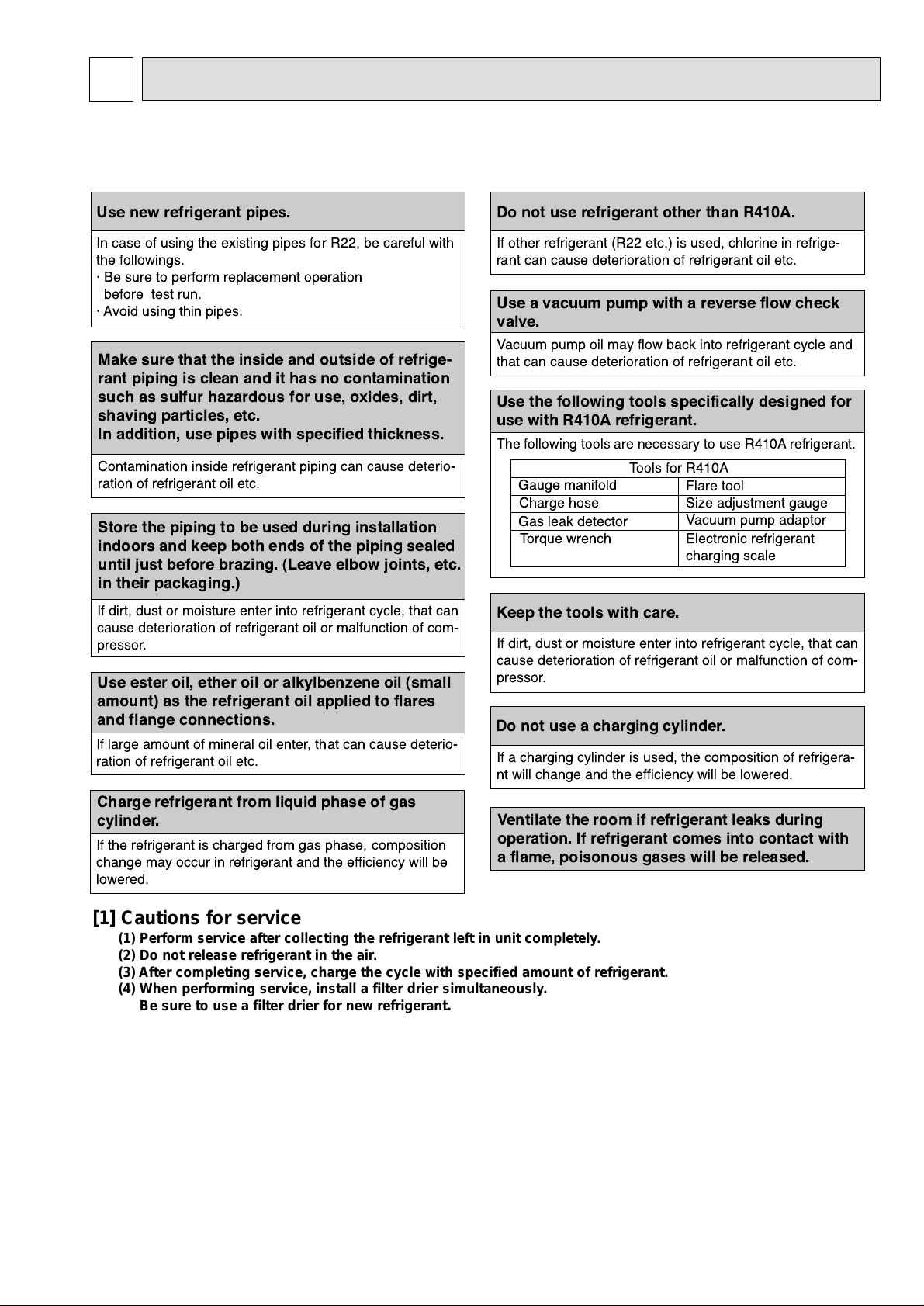
CAUTIONS RELATED TO NEW REFRIGERANT
Use new refrigerant pipes.
Make sure that the inside and outside of refrige-
rant piping is clean and it has no contamination
such as sulfur hazardous for use, oxides, dirt,
shaving particles, etc.
In addition, use pipes with specified thickness.
Store the piping to be used during installation
indoors and keep both ends of the piping sealed
until just before brazing. (Leave elbow joints, etc.
in their packaging.)
Use ester oil, ether oil or alkylbenzene oil (small
amount) as the refrigerant oil applied to flares
and flange connections.
In case of using the existing pipes for R22, be careful with
the followings.
á Be sure to perform replacement operation
before test run.
á Avoid using thin pipes.
Charge refrigerant from liquid phase of gas
cylinder.
If the refrigerant is charged from gas phase, composition
change may occur in refrigerant and the efficiency will be
lowered.
Do not use refrigerant other than R410A.
If other refrigerant (R22 etc.) is used, chlorine in refrige-
rant can cause deterioration of refrigerant oil etc.
Use a vacuum pump with a reverse flow check
valve.
Vacuum pump oil may flow back into refrigerant cycle and
that can cause deterioration of refrigerant oil etc.
Use the following tools specifically designed for
use with R410A refrigerant.
The following tools are necessary to use R410A refrigerant.
Keep the tools with care.
If dirt, dust or moisture enter into refrigerant cycle, that can
cause deterioration of refrigerant oil or malfunction of com-
pressor.
Do not use a charging cylinder.
If a charging cylinder is used, the composition of refrigera-
nt will change and the efficiency will be lowered.
Flare tool
Electronic refrigerant
charging scale
Vacuum pump adaptor
Size adjustment gauge
Gauge manifold
Torque wrench
Gas leak detector
Charge hose
Tools for R410A
Contamination inside refrigerant piping can cause deterio-
ration of refrigerant oil etc.
If dirt, dust or moisture enter into refrigerant cycle, that can
cause deterioration of refrigerant oil or malfunction of com-
pressor.
If large amount of mineral oil enter, that can cause deterio-
ration of refrigerant oil etc.
Ventilate the room if refrigerant leaks during
operation. If refrigerant comes into contact with
a flame, poisonous gases will be released.
[1] Cautions for service
(1) Perform service after collecting the refrigerant left in unit completely.
(2) Do not release refrigerant in the air.
(3) After completing service, charge the cycle with specified amount of refrigerant.
(4) When performing service, install a filter drier simultaneously.
Be sure to use a filter drier for new refrigerant.
Page 4
4
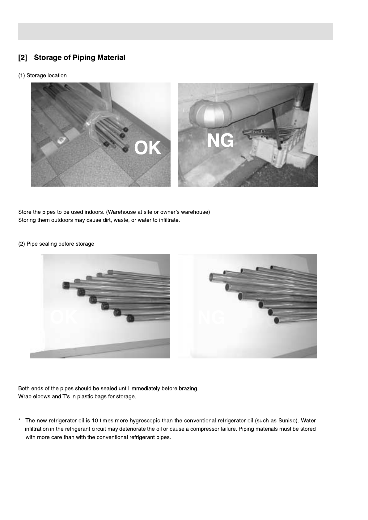
[2] Storage of Piping Material
(1) Storage location
Store the pipes to be used indoors. (Warehouse at site or ownerÕs warehouse)
Storing them outdoors may cause dirt, waste, or water to infiltrate.
(2) Pipe sealing before storage
Both ends of the pipes should be sealed until immediately before brazing.
Wrap elbows and TÕs in plastic bags for storage.
* The new refrigerator oil is 10 times more hygroscopic than the conventional refrigerator oil (such as Suniso). Water
infiltration in the refrigerant circuit may deteriorate the oil or cause a compressor failure. Piping materials must be stored
with more care than with the conventional refrigerant pipes.
OK
OK
NG
NG
Page 5
5
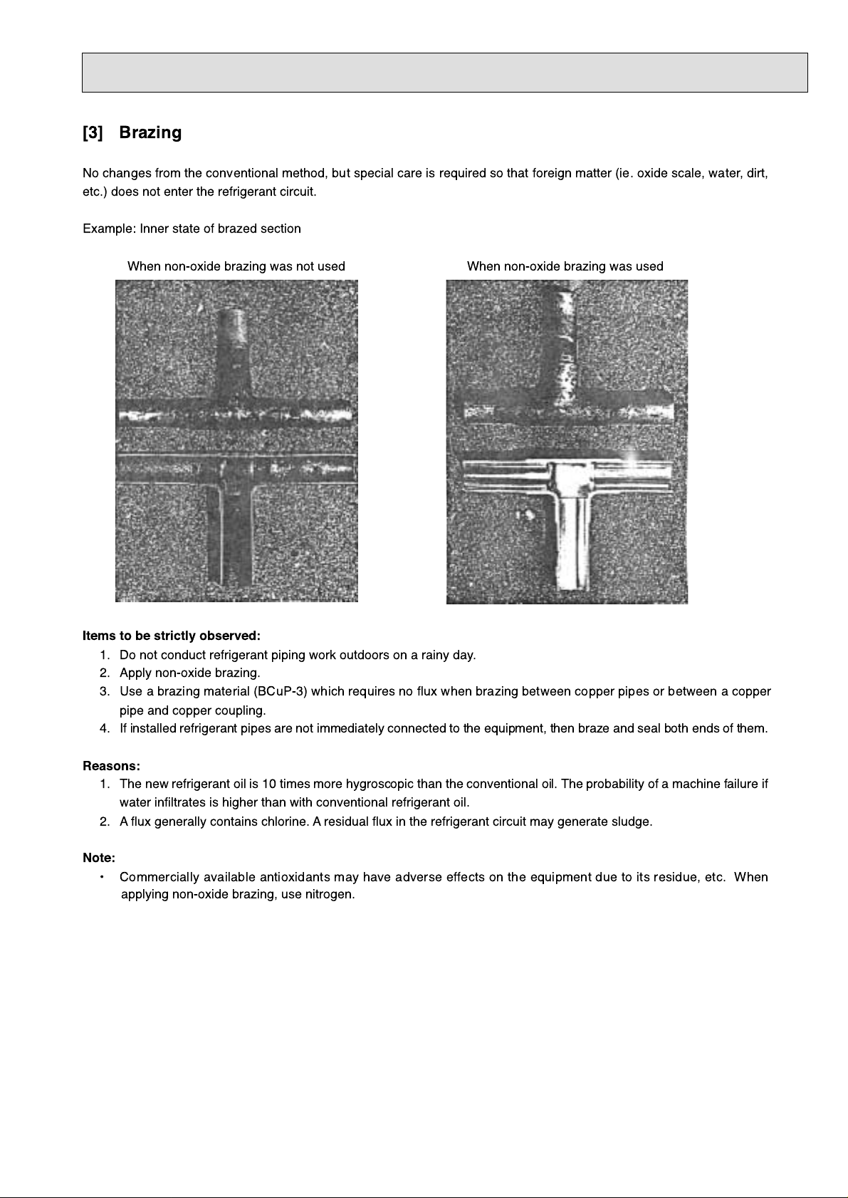
[3] Brazing
No changes from the conventional method, but special care is required so that foreign matter (ie. oxide scale, water, dirt,
etc.) does not enter the refrigerant circuit.
Example: Inner state of brazed section
When non-oxide brazing was not used When non-oxide brazing was used
Items to be strictly observed:
1. Do not conduct refrigerant piping work outdoors on a rainy day.
2. Apply non-oxide brazing.
3. Use a brazing material (BCuP-3) which requires no flux when brazing between copper pipes or between a copper
pipe and copper coupling.
4. If installed refrigerant pipes are not immediately connected to the equipment, then braze and seal both ends of them.
Reasons:
1. The new refrigerant oil is 10 times more hygroscopic than the conventional oil. The probability of a machine failure if
water infiltrates is higher than with conventional refrigerant oil.
2. A flux generally contains chlorine. A residual flux in the refrigerant circuit may generate sludge.
Note:
¥ Commercially available antioxidants may have adverse effects on the equipment due to its residue, etc. When
applying non-oxide brazing, use nitrogen.
Page 6
6
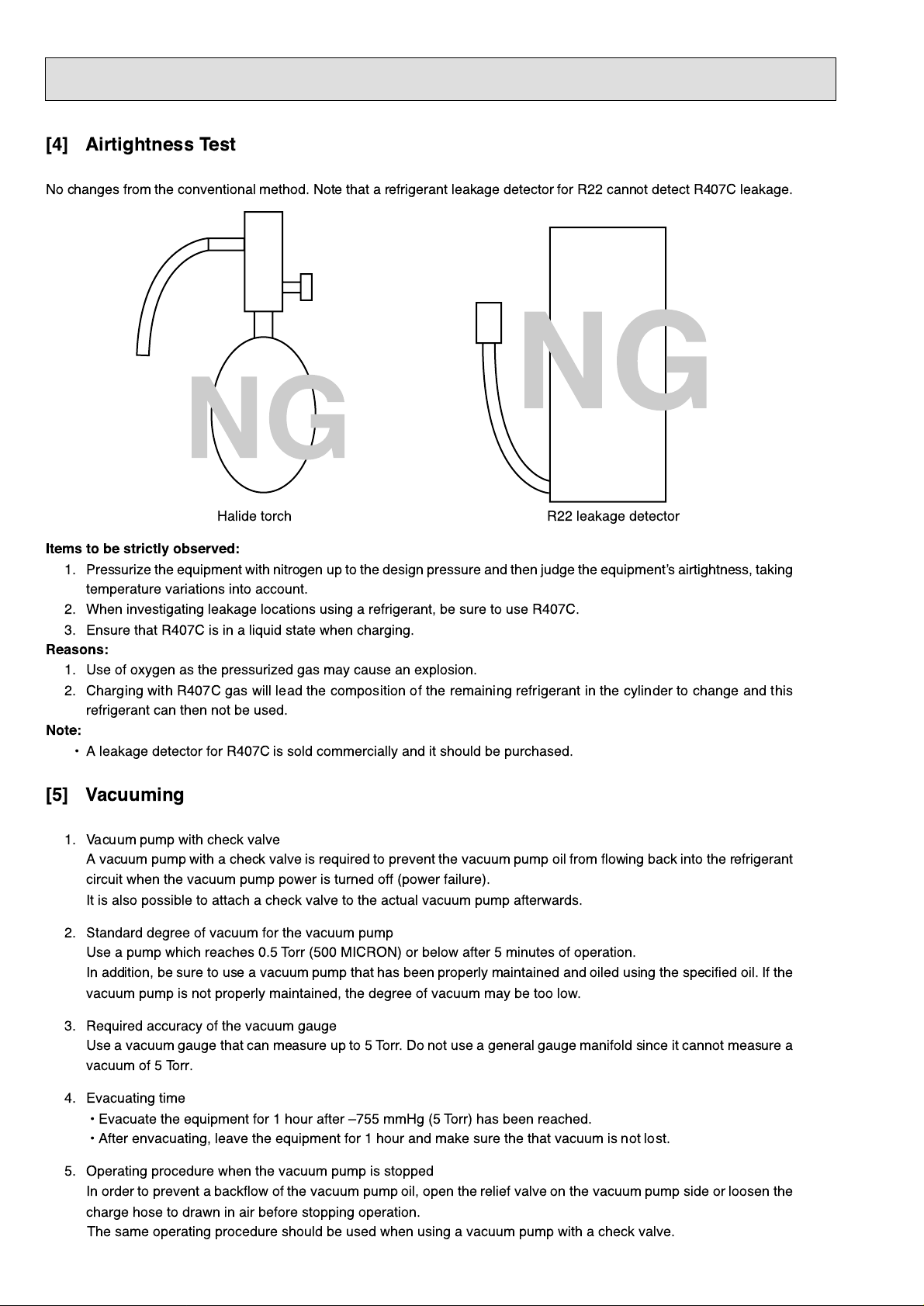
[4] Airtightness Test
No changes from the conventional method. Note that a refrigerant leakage detector for R22 cannot detect R407C leakage.
Halide torch R22 leakage detector
Items to be strictly observed:
1. Pressurize the equipment with nitrogen up to the design pressure and then judge the equipmentÕs airtightness, taking
temperature variations into account.
2. When investigating leakage locations using a refrigerant, be sure to use R407C.
3. Ensure that R407C is in a liquid state when charging.
Reasons:
1. Use of oxygen as the pressurized gas may cause an explosion.
2. Charging with R407C gas will lead the composition of the remaining refrigerant in the cylinder to change and this
refrigerant can then not be used.
Note:
¥ A leakage detector for R407C is sold commercially and it should be purchased.
[5] Vacuuming
1. Vacuum pump with check valve
A vacuum pump with a check valve is required to prevent the vacuum pump oil from flowing back into the refrigerant
circuit when the vacuum pump power is turned off (power failure).
It is also possible to attach a check valve to the actual vacuum pump afterwards.
2. Standard degree of vacuum for the vacuum pump
Use a pump which reaches 0.5 Torr (500 MICRON) or below after 5 minutes of operation.
In addition, be sure to use a vacuum pump that has been properly maintained and oiled using the specified oil. If the
vacuum pump is not properly maintained, the degree of vacuum may be too low.
3. Required accuracy of the vacuum gauge
Use a vacuum gauge that can measure up to 5 Torr. Do not use a general gauge manifold since it cannot measure a
vacuum of 5 Torr.
4. Evacuating time
¥ Evacuate the equipment for 1 hour after Ð755 mmHg (5 Torr) has been reached.
¥ After envacuating, leave the equipment for 1 hour and make sure the that vacuum is not lost.
5. Operating procedure when the vacuum pump is stopped
In order to prevent a backflow of the vacuum pump oil, open the relief valve on the vacuum pump side or loosen the
charge hose to drawn in air before stopping operation.
The same operating procedure should be used when using a vacuum pump with a check valve.
NG
NG
Page 7
7
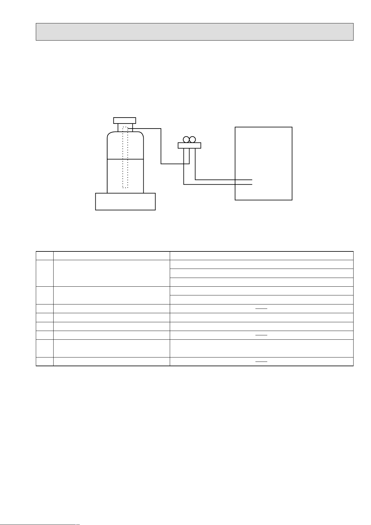
[6] Additional refrigerant charge
When charging directly from cylinder
· Check that cylinder for R410A on the market is syphon type.
· Charging should be performed with the cylinder of syphon stood vertically. (Refrigerant is charged from liquid phase.)
[7] Service tools
Use the below service tools as exclusive tools for R410A refrigerant.
No. Specifications
1 Gauge manifold ·Only for R410A
·Use the existing fitting
specifications
. (UNF1/2)
·Use high-tension side pressure of 5.3MPa·G or over.
2 Charge hose ·Only for R410A
·Use pressure performance of 5.09MPa·G or over.
3 Electronic scale
4 Gas leak detector ·Use the detector for R134a, R407C or R410A.
5 Adaptor for reverse flow check ·Attach on vacuum pump.
6 Refrigerant charge base
7 Refrigerant cylinder ·Only for R410A Top of cylinder (Pink)
Cylinder with syphon
8 Refrigerant recovery equipment
Gravimeter
Unit
Page 8
8
3
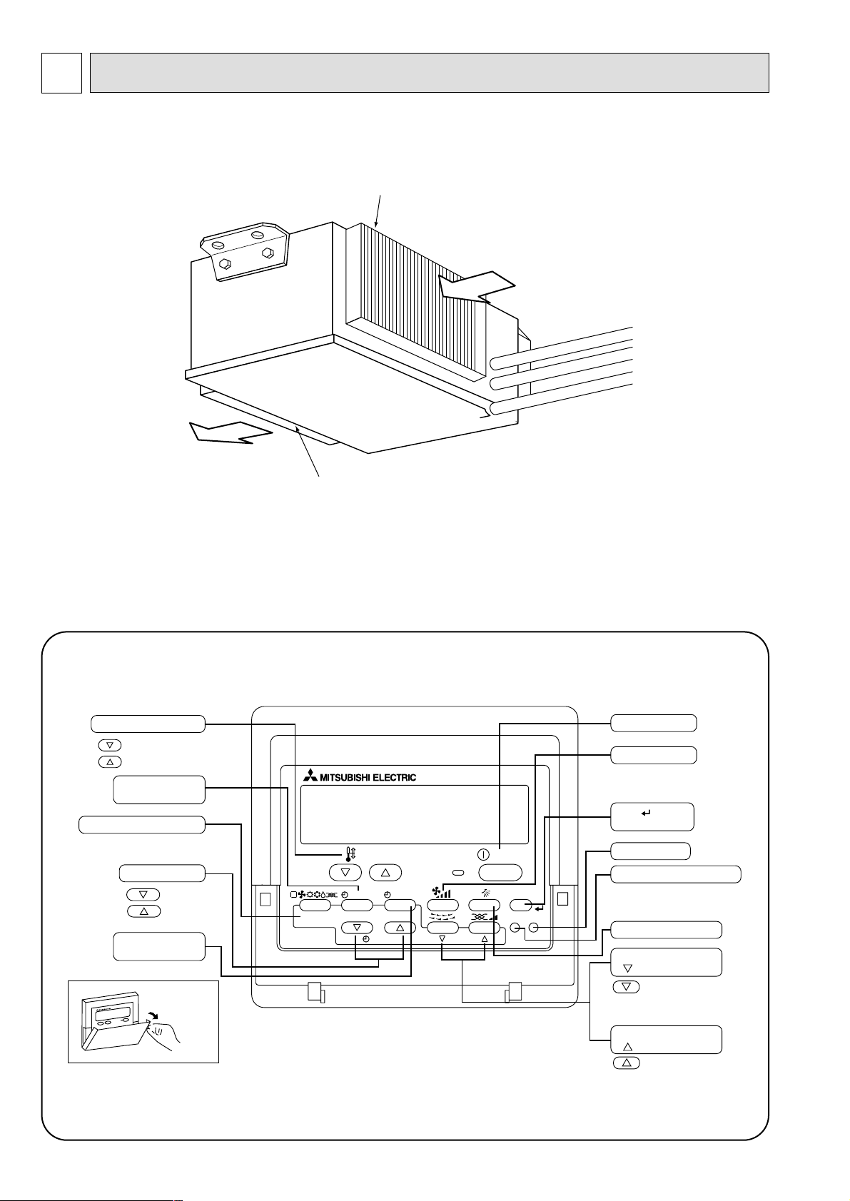
PART NAMES AND FUNCTIONS
● Remote controller
Once the controls are set, the same operation mode can be repeated by simply pressing the ON/OFF button.
● Operation buttons
● Indoor Unit
PEA-RP200GA
PEA-RP250GA
PEA-RP400GA
PEA-RP500GA
Air intake duct flange
Air outlet duct flange
Air outlet
Air intake
(sucks the air inside the room into the unit)
PAR-21MAA
ON/OFF
FILTER
CHECK
OPERATION
CLEAR
TEST
TEMP.
MENU
BACK DAY
MONITOR/SET
CLOCK
ON/OFF
Set Temperature buttons
Down
Up
Timer Menu button
(Monitor/Set button)
Mode button (Return button)
Set Time buttons
Back
Ahead
Timer On/Off button
(Set Day button)
Opening the
door.
ON/OFF button
Fan Speed button
Filter button
(<Enter> button)
Test Run button
Check button (Clear button)
Airflow Up/Down button
Louver button
(
Operation button)
To preceding operation
number.
Ventilation button
(
Operation button)
To next operation number.
Page 9
9
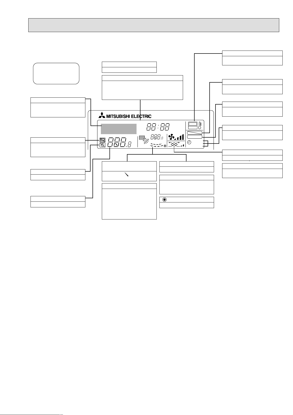
● Display
For purposes of this explanation,
all parts of the display are shown
as lit. During actual operation, only
the relevant items will be lit.
˚F˚C
˚F˚C
ERROR CODE
AFTER
TIMER
TIME SUN MON TUE WED THU FRI SAT
ON
OFF
Hr
AFTER
FILTER
FUNCTION
ONLY1Hr.
WEEKLY
SIMPLE
AUTO OFF
Identifies the current operation
Shows the operating mode, etc.
* Multilanguage display is sup-
ported.
“Centrally Controlled” indicator
Indicates that operation of the remote controller has been prohibited by a master controller.
“Timer Is Off” indicator
Indicates that the timer is off.
Temperature Setting
Shows the target temperature.
Day-of-Week
Shows the current day of the week.
Time/Timer Display
Shows the current time, unless the simple or Auto Off
timer is set.
If the simple or Auto Off timer is set, shows the time
remaining.
“Sensor” indication
Displayed when the remote controller
sensor is used.
“Locked” indicator
Indicates that remote controller buttons have been locked.
“Clean The Filter” indicator
Comes on when it is time to clean the
filter.
Timer indicators
The indicator comes on if the corresponding timer is set.
Up/Down Air Direction indicator
The indicator shows the direction of the outcoming airflow.
“One Hour Only” indicator
Displayed if the airflow is set to
weak and downward during COOL
or DRY mode. (Operation varies
according to model.)
The indicator goes off after one
hour, at which time the airflow direction also changes.
Room Temperature display
Shows the room temperature.
Louver display
Indicates the action of the swing
louver. Does not appear if the
louver is stationary.
(Power On indicator)
Indicates that the power is on.
Fan Speed indicator
Shows the selected fan speed.
Ventilation indicator
Appears when the unit is running in
Ventilation mode.
Caution
● Only the Power on indicator lights when the unit is stopped and power supplied to the unit.
● If you press a button for a feature that is not installed at the indoor unit, the remote controller will display the “Not Available”
message.
If you are using the remote controller to drive multiple indoor units, this message will appear only if he feature is not
present at the parent unit.
● When power is turned ON for the first time, it is normal that “PLEASE WAIT” is displayed on the room temperature indica-
tion (For max. 2minutes). Please wait until this “PLEASE WAIT” indication disappear then start the operation.
Page 10
10
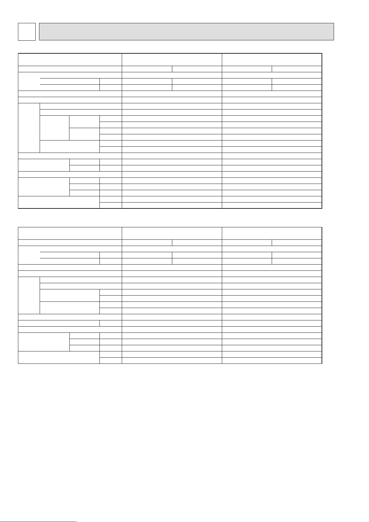
4
SPECIFICATIONS
Model name
Cooling
1.00
1.8
Heating
1.00
1.8
H
W
D
Hi
Lo
kW
A
CMM
L/s
CMM
L/s
Pa
mmAq
dB(A)
dB(A)
mm
mm
mm
kg
lbs
PEA-RP200GA PEA-RP250GA
3PH 4W 50Hz 380-415V
Galvanized steel
Cross fin coil
Centrifugal (direct) o2
0.77
65
1083
52
867
150
15
Remote control & built in
51
48
R1
400
1400
634
70
154
Cooling
1.10
2.1
Heating
1.10
2.1
3PH 4W 50Hz 380-415V
Galvanized steel
Cross fin coil
Centrifugal (direct) o2
0.77
80
1333
64
1067
150
15
Remote control & built in
52
49
R1
400
1600
634
77
169
Power supply (phase, cycle,voltage)
Input
Running current
External finish
Heat exchanger
Operation control & Thermostat
Sound level
Drain connection
Dimensions
Weight
Mode
Fan (drive) o No.
Fan motor output
Airflow
External static pressure
Hi
Lo
Model name
Cooling
1.55
3.8
Heating
1.55
3.8
H
W
D
kW
A
CMM
L/s
Pa
mmAq
dB(A)
mm
mm
mm
kg
lbs
PEA-RP400GA PEA-RP500GA
3PH 4W 50Hz 380-415V
Galvanized steel
Cross fin coil
Centrifugal (direct) o2
1.3
120
2,000
150
15
Remote control & built in
52
R1
595
1947
764
130
286
Cooling
2.84
5.4
Heating
2.84
5.4
3PH 4W 50Hz 380-415V
Galvanized steel
Cross fin coil
Centrifugal (direct) o2
1.8
160
2,667
150
15
Remote control & built in
53
R1
595
1947
764
133
293
Power supply (phase, cycle,voltage)
Input
Running current
External finish
Heat exchanger
Operation control & Thermostat
Sound level
Drain connection
Dimensions
Weight
Mode
Fan (drive) o No.
Fan motor output
Airflow
External static pressure
Fan
Fan
Page 11
11
DATA5
5-1. Sound Data
Indoor units
Indoor unit
Position measurement
Measurement point
Inlet
Outlet
1.5m
2m
1m
PEA-RP200,250: Upper High/Lower Low
SPL
dB(A) 63Hz 125Hz 250Hz 500Hz 1000Hz 2000Hz 4000Hz 8000Hz
51 55 54 51 49 47 43 33 27
48 50 50 47 46 44 40 29 21
52 56 55 52 50 48 44 34 28
49 51 51 48 47 45 41 30 22
53 55 54 51 50 48 44 40 31
52 53 51 52 50 46 44 39 30
PEA-RP200GA
PEA-RP250GA
PEA-RP500GA
PEA-RP400GA
Model
OCTAVE BAND FREQ.Hz
Page 12

12
5-2. Fan Performance Curve
Indoor units
PEA-RP200GA
Fan Performance Curve 50Hz
PEA-RP250GA
Fan Performance Curve 50Hz
PEA-RP400GA
Fan Performance Curve 50Hz
PEA-RP500GA
Fan Performance Curve 50Hz
70.0 80.0 100.0 110.0 120.0 130.090.0
(Pa)
(Pa) (Pa)
External static pressure
Air flow
(CMM)
0
50
100
150
200
300
250
110.0100.0 120.0 130.0 140.0 150.0 160.0 170.0
(Pa)
External static pressure
Air flow
(CMM)
0
50
100
150
200
350
300
250
Hi
Lo
45.0 50.0 55.0 60.0 65.0 70.0
Hi
Lo
0
50
100
150
200
250
300
0
50
100
150
200
250
60.0 65.0 70.0 75.0 80.0 85.0 90.0
External static pressure
Air flow Air flow
(CMM)
(CMM)
External static pressure
Page 13

13
OUTLINES AND DIMENSIONS
6
Return air
sensor
A
Rubber bush <Remote
controller wiring>
Rubber bush
<Outdoor unit
connection wiring>
Rubber bush
<Power supply
wiring>
A
4-
ø
12 Holes
Drain R1
Top view
Control box
Return air
duct flange
Supply air
duct flange
<For hanging bolt M10>
[Field supply]
22-
ø
3.1 Holes
24-
ø
3 Holes
Refrigerant pipe
ø
9.52 (3/8 braze)
Refrigerant pipe
ø
25.4 (1 braze)
<Accessory>
2pcs.
·
Pipe cover ··································
(For dew condensation prevention of
local piping and unit connection.)
1pc.
·
Remote controller························
Return air
Left side view
Supply air
Front view
75
55
12970
42
124 34
131
530
50
9525011
7x130(=910)
10
130
130
45
45
31 31
1102
200
10
8x130(=1040)
1300
20
199
100
40
20
462
144
1284
400
155 1000 105
40 1260 40
1340
1400
56539
22330
145
89
35
130
130
35
634
262 73
10
54
10
376
2510010025
Unit : mm
PEA-RP200GA
Page 14

14
Unit : mm
PEA-RP250GA
Rubber bush <Remote
controller wiring>
Rubber bush
<Outdoor unit
connection wiring>
Rubber bush
<Power supply
wiring>
A
A
4-
ø
12 Holes
Drain R1
Top view
Control box
22-
ø
3.1 Holes
<For hanging bolt M10>
[Field supply]
Return air
duct flange
Supply air
duct flange
26-
ø
3 Holes
Left side view
Supply air
Return air
Front view
Return air
sensor
<Accessory>
·Pipe cover ································· 2pcs.
(For dew condensation prevention of
local piping and unit connection.)
·Remote controller ······················ 1pc.
Refrigerant pipe
ø
12.7 (1/2 braze)
Refrigerant pipe
ø
25.4 (1 braze)
42
144145
755570 129
124
131
50 530
34
130
9525011
10
66
1302
1484
7x130(=910)
130
45
45
200
20
100
20
199
40
1500
462
66 9X130(=1170)
10
25 100 100 25
10 10
1540
40146040
255 205
376
1000
1600
73262
400
39 565
54
634
35
130
89
330 22
130
35
Page 15

15
PEA-RP400,500GA
45
Refrigerant pipe
PEA-RP400GA : ø9.52 (3/8 braze)
PEA-RP500GA : ø12.7 (1/2 braze)
[2 places (*2 part)]
*2*1*2
*1
Refrigerant pipe ø25.4 (1 braze)
[2 places (*1 part)]
Return air sensor
(2 places)
Drain R1
24- ø3.1 HOLES
36- ø3 HOLES
Left side view
Front view
Top view
Return air
Supply air
4- ø15 HOLES
<For hanging bolt M12>
[Field supply]
Return air duct flange
Control box
Supply air duct flange
A
Rubber bush
<Remote controller wiring>
Rubber bush
<Power supply wiring>
Rubber bush
<Outdoor unit connection wiring>
A
<Accessory>
·Pipe cover ································· 4pcs.
(For dew condensation prevention of
local piping and unit connection.)
·Remote controller ······················ 1pc.
81
117156117
10
20 1840
10
40
60
60
61
60
4040
1800
1880
50 664
525
22
102
22.5
120
4X120(=480)
22.5
595
1824
50
764
2801125395
340 18822
1947
570
40 130 130 40
10
33
29
130
12X130(=1560)
29
149 1618
100
42.5
130
8X130(=1040)42.5
10
203320141
20
42559
700
39
Unit : mm
Page 16

16
7
WIRING DIAGRAM
PEA-RP200,250GA
OUTDOOR UNIT
CIRCUIT BREAKER
(FIELD SUPPLY)
PEA-RP200,250GA:15A
DSR
DSA
(3P)
(Hi)
C02
(6P)
(Lo)
C01
C01
5
4
TH5
TH2
TH1
INDOOR UNIT
POWER SUPPLY
3N~PE
380/400/415V
50Hz
BLACK
WHITE
RED
N
BLACK
WHITE
RED
TB2
L3
L2
L1
PE
52F
Hi
Lo
321
52F
123
MF1
TB6
LCD
REMOTE CONTROLLER
FB
TB4
S3
S2
S1
X6X5X4
375 1
FAN
ZNR
FUSE
4123
SW2
OFF
ON
5
TAB1
3
1
CNSK
2
1
CN2S
DC
13.1V
CN2D
CN90
CN22
CN2L
CNDK
CND
CN32
CN31
CN51
12345
31
31
3112
DC13.1V
LED1
LED2
LED3
21212
1
213
365
4
987
312
CN3C
CN20
CN21
CN41
CN29
123
4
121
2
2
1
1
2
TB5
Hi
52F
Lo
52F
X1
X1
X1
49F
51F
X6X5X4
12345
SW1
OFF
ON
SWE
OFF
ON
SWITCH (MODEL SELECTION)
SWITCH (CAPACITY CODE)
CONNECTOR (EMERGENCY OPERATION)
SNB
BOARD 1
ZNR5~7 VARISTOR
DSA,DSR ARRESTER
INDOOR UNIT
NAMESYMBOL
COND/EVA TEMP
LIQUID PIPE TEMP
ROOM TEMP
52FHi MAGNETIC CONTACTOR (INDOOR FAN MOTOR<HIGH SPEED>)
SURGE KILLERCR1,2
SW1
TH5
LED (TRANSMISSION<INDOOR
·
OUTDOOR>)LED3
LED (POWER SUPPLY<REMOTE CONTROLLER>)LED2
LED (POWER SUPPLY)LED1
SWE
SW2
X4-6 AUXILIARY RELAY
VARISTORZNR
FUSE (T6.3AL250V)FUSE
THERMISTOR
TERMINAL BLOCK
INTERNAL THERMOSTAT (INDOOR FAN MOTOR)
OVER CURRENT RELAY (INDOOR FAN MOTOR)
FAN MOTOR (INDOOR)
TH2
TH1
TB2,4,5
49F
51F
MF1
52FLo MAGNETIC CONTACTOR (INDOOR FAN MOTOR<LOW SPEED>)
AUXILIARY RELAYX1
FERRITE COREFB
BOARD
CONTROLLER
INDOOR
CN2L
CN31
CN90
CN51
CN41
CN32
CONNECTOR (DRAIN SENSOR)
CONNECTOR (REMOTE SWITCH)
CONNECTOR (HA TERMINAL-A)
CONNECTOR (CENTRALLY CONTROL)
CONNECTOR (WIRELESS REMOTE CONTROLLER)
CONNECTOR (LOSSNAY)
4.Indoor and outdoor connecting wires are made with polarities,make sure
matching wiring and terminal.
5.Emergency operation
If a trouble occurs with either the remote controller or the indoor microcom-
puter and no other trouble exists, emergency operation for cooling or heating
can be performed by changing the setting of connector (SWE) "ON" on the
indoor controller board.
SWE :ON / Indoor fan is running high speed.
TERMINAL BLOCKTB6
SYMBOL
REMOTE CONTROLLER
NAME
SNB BOARD 1
REMOTE
CONTROLLER
BOARD
POWER BOARD
INDOOR
INDOOR
CONTROLLER
BOARD
Note:1.The dotted lines show field wiring.
2.Color of earth wire is yellow and green twisting.
3.Specification subject to change without notice.
51F
Caution,
1.To protect fan motor from abnormal current,over current relays is installed.
Therefore, do not change factory set value of over current relays.
6. mark is connector. mark is terminal.
CR1CR2
ZNR5~7
TO OUTDOOR UNIT
CONNECTING WIRES
(POLAR)
Page 17

17
PEA-RP400,500GA
GREEN/YELLOW
INDOOR UNIT
OUTDOOR UNIT
OUTDOOR UNIT
TAB1
TAB1
FAN
CNDK
31
1573
X4 X5 X6
CN20
CN21
CN41
CN29
123
4
121
2
2
1
CN2D
CN90
CN22
CN2L
CND
CN32
CN31
CN51
12345
FUSE
ZNR
31
3112
DC13.1V
LED1
LED2
LED3
21212
1
213
365
4
987
312
CN3C
3
1
CNSK
2
1
CN2S
DC
13.1V
3
1
CNSK
2
1
CN2S
DC
13.1V
CN2D
CN90
CN22
CN2L
FAN
CNDK
CND
CN32
CN31
CN51
12345
FUSE
ZNR
31
31
3112
DC13.1V
1573
X4 X5 X6
LED1
LED2
LED3
21212
1
213
365
4
987
312
CN3C
CN20
CN21
CN41
CN29
123
4
121
2
2
1
FB11
S1
1
2
REMOTE CONTROLLER
S2
S3
TB5
TB6
LCD
X1
FB21
S1S2S3
X2
TH1-1
TH2-1
TH5-1
TH5-2
TH2-2
TH1-2
TB4-2
TB4-1
FB12
FB22
X4 X5 X6
X4 X5 X6
51F
BLUE
POWER SUPPLY
3N~PE
380/400/415V
50Hz
CIRCUIT BREAKER
(FIELD SUPPLY)
PEA-RP400,500GA:15A
BLACK
WHITE
RED
DSR
DSA
N
BLACK
WHITE
RED
TB2
L3
L2
L1
PE
52F
C01 C02
123
MF1
123
52F
C01
5
4
X01
X02
49F
SWE
OFF
ON
345
SW1
OFF
ON5ON
OFF
34
12
21
SWE
OFF
ON
345
SW1
OFF
ON5ON
OFF
SW2
34
12
21
SW2
AUXILIARY RELAYX4-6
MF1
51F
49F
TB2,4-1,4-2,5
TH1-1,1-2
TH2-1,2-2
FAN MOTOR (INDOOR)
OVER CURRENT RELAY (INDOOR FAN MOTOR)
INTERNAL THERMOSTAT (INDOOR FAN MOTOR)
TERMINAL BLOCK
THERMISTOR
INDOOR UNIT
FUSE FUSE (T6.3AL250V)
ZNR VARISTOR
TH5-1,5-2
CR SURGE KILLER
MAGNETIC CONTACTOR (INDOOR FAN MOTOR)52F
ROOM TEMP
LIQUID PIPE TEMP
COND/EVA TEMP
FERRITE COREFB11,FB12
FB21,FB22
INDOOR
CONTROLLER
BOARD
X1,2 AUXILIARY RELAY
NAMESYMBOL
SNB
BOARD 1
ZNR5~7 VARISTOR
DSA,DSR ARRESTER
SW2
SWE
LED1 LED (POWER SUPPLY)
LED2 LED (POWER SUPPLY<REMOTE CONTROLLER>)
LED3 LED (TRANSMISSION<INDOOR
·
OUTDOOR>)
SWITCH (MODEL SELECTION)SW1
SWITCH (CAPACITY CORD)
CONNECTOR (EMERGENCY OPERATION)
OUTDOOR UNIT
TERMINAL BLOCK
NAMESYMBOL
TB3,TB8
CN2L
CN31
CN90
CN51
CN41
CN32
CONNECTOR (DRAIN SENSOR)
CONNECTOR (REMOTE SWITCH)
CONNECTOR (HA TERMINAL-A)
CONNECTOR (CENTRALLY CONTROL)
CONNECTOR (WIRELESS REMOTE CONTROLLER)
CONNECTOR (LOSSNAY)
REMOTE CONTROLLER
TERMINAL BLOCK
NAMESYMBOL
TB6
4.Indoor and outdoor connecting wires are made with polarities,make sure
matching wiring and terminal.
5.Emergency operation
If a trouble occurs with either the remote controller or the indoor microcom-
puter and no other trouble exists, emergency operation for cooling or heating
can be performed by changing the setting of connector (SWE) "ON" on the
indoor controller board.
SWE :ON / Indoor fan is running high speed.
(No.2)
INDOOR
CONTROLLER
BOARD
(No.1)
REMOTE
CONTROLLER
BOARD
INDOOR
POWER
BOARD
(No.1)
(No.2)
INDOOR
CONTROLLER
BOARD
(No.2)
TO OUTDOOR UNIT
CONNECTING WIRES
(POLAR)
TO OUTDOOR UNIT
CONNECTING WIRES
(POLAR)
SNB BOARD 1
(No.1)
INDOOR
POWER BOARD
Note:1.The dotted lines show field wiring.
2.Color of earth wire is yellow and green twisting.
3.Specification subject to change without notice.
51F
6. mark is connector. mark is terminal.
Caution,
1.To protect fan motor from abnormal current,over current relays is installed.
Therefore, do not change factory set value of over current relays.
CR
ZNR5~7
Page 18

18
PEA-RP200GA PEA-RP250GA
PEA-RP400GA PEA-RP500GA
Unit : mm
Pipe temperature
thermistor/liquid
(TH2)
Distributor
Condenser/evaporator
temperature thermistor
(TH5)
Room temperature
thermistor (TH1)
Refrigerant flow in cooling
Refrigerant flow in heating
Strainer
Strainer
Heat exchanger
Refrigerant GAS pipe connection
Brazing
Refrigerant LIQUID pipe connection
Brazing
8
REFRIGERANT SYSTEM DIAGRAM
Page 19

19
9 TROUBLESHOOTING
<Error code display by self-diagnosis and actions to be taken for service (summary)>
Present and past error codes are logged and displayed on the wired remote controller or controller board of outdoor unit.
Actions to be taken for service and the inferior phenomenon reoccurrence at field are summarized in the table below. Check
the contents below before investigating details.
9-1. TROUBLESHOOTING
Unit conditions at service
Error code
Actions to be taken for service (summary)
The inferior phenomenon is
reoccurring.
Displayed
Not displayed
Judge what is wrong and take a corrective action
according to “SELF-DIAGNOSIS ACTION TABLE” (9-2).
Identify the cause of the inferior phenomenon and take
a corrective action according to “TROUBLESHOOTING
BY INFERIOR PHENOMENA ” (9-3).
The inferior phenomenon is
not reoccurring.
Logged
Not logged
1Consider the temporary defects such as the work of
protection devices in the refrigerant circuit including
compressor, poor connection of wiring, noise and etc.
Re-check the symptom, and check the installation
environment, refrigerant amount, weather when the
inferior phenomenon occurred, and wiring related.
2Reset error code logs and restart the unit after finishing
service.
3There is no abnormality in electrical components,
controller boards, and remote controller.
1Recheck the abnormal symptom.
2Identify the cause of the inferior phenomenon and take
a corrective action according to “TROUBLESHOOTING
BY INFERIOR PHENOMENA ” (9-3).
3Continue to operate unit for the time being if the cause
is not ascertained.
4There is no abnormality in electrical components,
controller boards, remote controller etc.
Page 20

20
9-2. SELF-DIAGNOSIS ACTION TABLE
Note: Refer to the manual of outdoor unit for the details of display
such as F, U, and other E.
Error Code
Meaning of error code and detection method
Cause
Countermeasure
P1
Abnormality of room temperature
thermistor (TH1)
1 The unit is in three-minute resume
prevention mode if short/open of
thermistor is detected. Abnormal if the
unit does not reset normally after three
minutes. (The unit returns to normal
operation, if it has normally reset.)
2 Constantly detected during cooling,
drying, and heating operation.
Short: 90
: or more
Open: -40
: or less
1 Defective thermistor
characteristics.
2 Contact failure of connector
(CN20) on the indoor controller
board. (Insert failure)
3 Breaking of wire or contact
failure of thermistor wiring.
4 Defective indoor controller
board.
1~3 Check resistance value of thermistor.
0
: ······15.0k"
10: ····9.6k"
20: ····6.3k"
30: ····4.3k"
40: ····3.0k"
If you put force on (draw or bend) the lead wire
with measuring resistance value of thermistor
breaking of wire or contact failure can be
detected.
2 Check contact failure of connector (CN20) on
the indoor controller board. Refer to 9-6.
Turn the power on again and check restart
after inserting connector again.
4 Check room temperature display on remote
controller.
Replace indoor controller board if there is
abnormal difference with actual room
temperature.
Turn the power off, and on again to operate
after check.
P2
Abnormality of pipe temperature
thermistor/Liquid (TH2)
1 The unit is in three-minute resume
prevention mode if short/open of
thermistor is detected. Abnormal if the
unit does not reset normally after three
minutes. (The unit returns to normal
operation, if it has normally reset.)
2 Constantly detected during cooling,
drying, and heating (except defrosting)
operation.
Short: 90
: or more
Open: -40
: or less
1 Defective thermistor
characteristics.
2 Contact failure of connector
(CN21) on the indoor controller
board. (Insert failure)
3 Breaking of wire or contact
failure of thermistor wiring.
4 Defective refrigerant circuit is
causing thermistor temperature
of 90
: or more or -40: or
less.
5 Defective indoor controller board.
1~3 Check resistance value of thermistor.
For characteristics, refer to (P1) above.
2 Check contact failure of connector (CN21) on
the indoor controller board. Refer to 9-6. Turn
the power on and check restart after inserting
connector again.
4 Check pipe <liquid> temperature with remote
controller in test run mode. If pipe <liquid>
temperature is exclusively low (in cooling
mode) or high (in heating mode), refrigerant
circuit may have defective.
5 Check pipe <liquid> temperature with remote
controller in test run mode. If there is exclusive
difference with actual pipe <liquid> temperature,
replace indoor controller board.
Turn the power off, and on again to operate
after check.
P4
Abnormality of drain sensor (DS)
1 Suspensive abnormality, if short/open of
thermistor is detected for 30 seconds
continuously.
Turn off compressor and indoor fan.
2 Short/open is detected for 30 seconds
continuously during suspensive
abnormality.
(The unit returns to normal operation,
if it has normally reset.)
3 Detect the following condition.
• During cooling and drying operation.
• In case that pipe <liquid> temperature
- room temperature <-10deg
(Except defrosting)
• When pipe <liquid> temperature or
room temperature is short/open
temperature.
• During drain pomp operation.
1 Defective thermistor
characteristics
2 Contact failure of connector
(CN31) on the indoor controller
board. (Insert failure).
3 Breaking of wire or contact
failure of drain sensor wiring.
4 Defective indoor controller board.
1~3 Check resistance value of thermistor.
0
: ······6.0k"
10: ····3.9k"
20: ····2.6k"
30: ····1.8k"
40: ····1.3k"
2 Check contact failure of connector (CN31) on
the indoor controller board. Refer to 9-6. Turn
the power on again and check restart after
inserting connector again.
4 Replace indoor controller board if drain
pump operates with the line of drain sensor
connector CN31-
1 and 2 is short-circuited,
and abnormality reappears.
Turn the power off, and on again to operate
after check.
P5
Malfunction of drain pump (DP)
1 Suspensive abnormality, if thermistor
of drain sensor is let heat itself and
temperature rises slightly. Turn off
compressor and indoor fan.
2 Drain pomp is abnormal if the condition
above is detected during suspensive
abnormality.
3 Constantly detected during drain pomp
operation.
1 Malfunction of drain pump
2 Defective drain
Clogged drain pump
Clogged drain pipe
3 Attached drop of water at the
drain sensor
• Drops of drain trickles from
lead wire.
• Clogged filter is causing
wave of drain.
4 Defective indoor controller board.
1 Check if drain-up machine works.
2 Check drain function.
3 Check the setting of lead wire of drain sensor
and check clogs of the filter.
4 Replace indoor controller board if drain
pump operates with the line of drain sensor
connector CN31-1 and 2 is short-circuited
and abnormality reappears.
Refer to 9-6.
Turn the power off, and on again to operate
after check.
Page 21

21
Error Code
Meaning of error code and detection method
Cause
Countermeasure
P6
Freezing/overheating protection is
working
1 Freezing protection (Cooling mode)
The unit is in six-minute resume prevention
mode if pipe <liquid or condenser/evaporator> temperature stays under
-15: for three minutes, three minutes
after the compressor started. Abnormal
if it stays under -15: for three minutes
again within 16 minutes after six-minute
resume prevention mode.
<Frost prevention mode>
If pipe <liquid or condenser-evaporator>
temperature is 2
: or below when 16
minutes has passed after compressor
starts operating, unit will start operating
in frost prevention mode which stops
compressor operation. After that, when
pipe <liquid or condenser/evaporator>
temperature stays 10: or more for 3
minutes, frost prevention mode will be
released and compressor will restart its
operation.
2 Overheating protection (Heating mode)
The units is in six-minute resume
prevention mode if pipe <condenser /
evaporator> temperature is detected as
over 70: after the compressor started.
Abnormal if the temperature of over
70: is detected again within 10 minutes
after six-minute resume prevention
mode.
P8
1 Slight temperature difference
between indoor room
temperature and pipe <liquid
or condenser / evaporator>
temperature thermistor
• Shortage of refrigerant
• Disconnected holder of pipe
<liquid or condenser /
evaporator> thermistor
• Defective refrigerant circuit
2 Converse connection of
extension pipe (on plural units
connection)
3 Converse wiring of indoor/
outdoor unit connecting wire
(on plural units connection)
4 Defective detection of indoor
room temperature and pipe
<condenser / evaporator>
temperature thermistor
5 Stop valve is not opened
completely.
(Cooling or drying mode)
1 Clogged filter (reduced airflow)
2 Short cycle of air path
3 Low-load (low temperature)
operation beyond the tolerance
range
4 Defective indoor fan motor
• Fan motor is defective.
• Indoor controller board is
defective.
5 Defective outdoor fan control
6 Overcharge of refrigerant
7 Defective refrigerant circuit
(clogs)
(Heating mode)
1 Clogged filter (reduced airflow)
2 Short cycle of air path
3 Over-load (high temperature)
operation beyond the tolerance
range
4 Defective indoor fan motor
• Fan motor is defective.
• Indoor controller board is
defective.
5 Defective outdoor fan control
6 Overcharge of refrigerant
7 Defective refrigerant circuit
(clogs)
8 Bypass circuit of outdoor unit
is defective.
(Cooling or drying mode)
1 Check clogs of the filter.
2 Remove shields.
4 Measure the resistance of fan motor's winding.
Measure the output voltage of fan's connector
(Relay fo r FAN) on the indoor controller
board.
∗The indoor controller board should be
normal when voltage of AC 220~240V is
detected while fan motor is connected.
Refer to 9-6.
5 Check outdoor fan motor.
67 Check operating condition of refrigerant
circuit.
(Heating mode)
1 Check clogs of the filter.
2 Remove shields.
4 Measure the resistance of fan motor's
winding.
Measure the output voltage of fan's connector
(Relay for FAN) on the indoor controller
board.
∗The indoor controller board should be
normal when voltage of AC 220~240V is
detected while fan motor is connected.
Refer to 9-6.
5 Check outdoor fan motor.
6~8Check operating condition of refrigerant
circuit.
Abnormality of pipe temperature
<Cooling mode>
Detected as abnormal when the pipe temperature is not in the cooling range 3 minutes later of compressor start and 6 minutes later of the liquid or condenser/evaporator pipe is out of cooling range.
Note 1) It takes at least 9 min. to detect.
Note 2) Abnormality P8 is not detected in
drying mode.
Cooling range : -3 deg ] (TH-TH1)
TH: Lower temperature between: liquid
pipe temperature (TH2) and condenser/evaporator temperature (TH5)
TH1: Intake temperature
<Heating mode>
When 10 seconds have passed after the
compressor starts operation and the hot
adjustment mode has finished, the unit is
detected as abnormal when
condenser/evaporator pipe temperature is
not in heating range within 20 minutes.
Note 3) It takes at least 27 minutes to
detect abnormality.
Note 4) It excludes the period of defrosting
(Detection restarts when defrosting
mode is over)
Heating range : 3 deg [ (TH5-TH1)
1~4Check pipe <liquid or condenser /
evaporator> temperature with room temperature display on remote controller and
outdoor controller circuit board.
Pipe <liquid or condenser / evaporator>
temperature display is indicated by
setting SW2 of outdoor controller circuit
board as follows.
23Check converse connection of extension
pipe or converse wiring of indoor/outdoor
unit connecting wire.
Conduct temperature check with outdoor
controller circuit board after connecting
‘A-Control Service Tool(PAC-SK52ST)’.
(
)
Page 22

22
Error Code
Meaning of error code and detection method
Cause
Countermeasure
P9
Abnormality of pipe temperature thermistor / Condenser-Evaporator (TH5)
1 The unit is in three-minute resume pro-
tection mode if short/open of thermistor
is detected. Abnormal if the unit does
not get back to normal within three minutes. (The unit returns to normal operation, if it has normally reset.)
2 Constantly detected during cooling, dry-
ing, and heating operation (except
defrosting)
Short: 90: or more
Open: -40: or less
1 Defective thermistor
characteristics
2 Contact failure of connector
(CN29) on the indoor controller
board. (Insert failure)
3 Breaking of wire or contact
failure of thermistor wiring.
4 Temperature of thermistor is
90: or more or -40: or less
caused by defective refrigerant
circuit.
5 Defective indoor controller
board.
1~3 Check resistance value of thermistor.
For characteristics, refer to (P1) above.
2 Check contact failure of connector (CN29)
on the indoor controller board.
Refer to 9-6.
Turn the power on and check restart after
inserting connector again.
4 Operate in test run mode and check pipe
<condenser / evaporator> temperature with
outdoor controller circuit board. If pipe
<condenser / evaporator> temperature is
exclusively low (in cooling mode) or high (in
heating mode), refrigerant circuit may have
defective.
5 Operate in test run mode and check pipe
<condenser / evaporator> temperature with
outdoor control circuit board. If there is
exclusive difference with actual pipe
<condenser / evaporator> temperature
replace indoor controller board.
There is no abnormality if none of above
comes within the unit.
Turn the power off and on again to operate.
E0
or
E4
Remote controller transmission
error(E0)/signal receiving error(E4)
1 Abnormal if main or sub remote con-
troller can not receive normally any
transmission from indoor unit of refrigerant address “0” for three minutes.
(Error code : E0)
2 Abnormal if sub remote controller could
not receive for any signal for two minutes. (Error code: E0)
1 Abnormal if indoor controller board can
not receive normally any data from
remote controller board or from other
indoor controller board for three minutes.
(Error code: E4)
2 Indoor controller board cannot receive
any signal from remote controller for two
minutes. (Error code: E4)
1 Check disconnection or looseness of indoor
unit or transmission wire of remote controller.
2 Set one of the remote controllers “main”.
If there is no problem with the action above.
3 Check wiring of remote controller.
• Total wiring length: max.500m
(Do not use cablex 3 or more)
• The number of connecting indoor units:
max.16units
• The number of connecting remote controller: max.2units
When it is not the above-mentioned problem of
1~3
4 Diagnose remote controllers.
a) When “RC OK” is displayed,
Remote controllers have no problem.
Put the power off, and on again to check.
If abnormality generates again, replace
indoor controller board.
b) When “RC NG” is displayed,
Replace remote controller.
c) When “RC E3” is displayed,
d) When “ERC 00-06” is displayed,
[ c),d)→Noise may be causing abnormality. ]
∗ If the unit is not normal after replacing
indoor controller board in group control,
indoor controller board of address “0”
may be abnormal.
E3
or
E5
Remote controller transmission
error(E3)/signal receiving error(E5)
1 Abnormal if remote controller could not
find blank of transmission path for six
seconds and could not transmit.
(Error code: E3)
2 Remote controller receives transmitted
data at the same time, compares the
data, and when detecting it, judges
different data to be abnormal 30
continuous times. (Error code: E3)
1 Abnormal if indoor controller board could
not find blank of transmission path.
(Error code: E5)
2 Indoor controller board receives trans-
mitted data at the same time, compares
the data,and when detecting it, judges
different data to be abnormal 30
continuous times. (Error code: E5)
1 Set a remote controller to main, and the
other to sub.
2 Remote controller is connected with only one
indoor unit.
3 The address changes to a separate setting.
4~6 Diagnose remote controller.
a) When “RC OK”is displayed, remote con-
trollers have no problem.
Put the power off,and on again to check.
When becoming abnormal again, replace
indoor controller board.
b)When “RC NG”is displayed, replace
remote controller.
c)When “RC E3”or “ERC 00-66”is displayed,
noise may be causing abnormality.
1 Contact failure at transmission
wire of remote controller
2 All remote controllers are set
as “sub” remote controller. In
this case, E0 is displayed on
remote controller, and E4 is
displayed at LED (LED1, LED2)
on the outdoor controller circuit
board.
3 Mis-wiring of remote controller.
4 Defective transmitting receiving
circuit of remote controller
5 Defective transmitting receiving
circuit of indoor controller board
of refrigerant address “0”.
6 Noise has entered into the
transmission wire of remote
controller.
1 Two remote controller are set
as “main.”
(In case of 2 remote con-
trollers)
2 Remote controller is connected
with two indoor units or more.
3 Repetition of refrigerant
address.
4 Defective transmitting receiving
circuit of remote controller.
5 Defective transmitting receiving
circuit of indoor controller
board.
6 Noise has entered into trans-
mission wire of remote controller.
In case of checking pipe temperature
with outdoor controller circuit board,
be sure to connect A-control service
tool (PAC-SK52ST).
(
)
Page 23

23
PA
(2502)
(2500)
Forced compressor stop
(due to water leakage abnormality)
1 When the intake temperature subtracted
with liquid pipe temperature is less than
-10
:, drain sensor is detected whether
it is soaked in the water or not at the interval
of 90 seconds. (Drain pump will start operating
when the drain sensor is detected to be
soaked in the water.)
2 The unit has a water leakage abnormality
when the following conditions, a and b, are
satisfied while the above-mentioned detection
is performed.
a) The drain sensor is detected to be
soaked in the water 10 times in a row.
b) The intake temperature subtracted with
liquid pipe temperature is detected to be
less than -10
: for a total of 30 minutes.
(When the drain sensor is detected to
be NOT soaked in the water, the detection
record of a and b will be cleared.)
3 The drain sensor detection is performed
in operations other than cooling. (When
the unit stops operating, during heating
or fan operation, when the unit stops
because of some abnormality)
*Once the water leakage abnormality is
detected, abnormality state will not be
released until the main power is reset.
1) Drain pump trouble
2) Drain defective
· Drain pump clogging
· Drain pipe clogging
3) Open circuit of drain sensor
side heater
4) Contact failure of drain sensor
connector
5) Dew condensation on drain
sensor
· Drain water descends along
lead wire.
· Drain water waving due to filter
clogging.
6) Extension piping connection
difference at twin, triple,
quadruple system.
7) Mis-wiring of indoor/ outdoor
connecting at twin, triple,
quadruple system.
8) Room temperature thermistor /
liquid pipe temperature thermistor detection is defective.
Check the drain pump.
Performance
Please confirm whether water can be drained.
Confirm the resistance of the drain sensor side
heater.
Check the connector contact failure.
1 Check the drain sensor leadwire mounted.
2 Check the filter clogging
Check the piping connection.
Check the indoor/ outdoor connecting wires.
Check the room temperature display of remote
controller.
Check the indoor liquid pipe temperature display of outdoor controller board.
E6
1 Contact failure, short circuit or,
mis-wiring (converse wiring) of
indoor/outdoor unit connecting
wire
2 Defective transmitting receiving
circuit of indoor controller board
3 Defective transmitting receiving
circuit of indoor controller board
4 Noise has entered into indoor/
outdoor unit connecting wire.
∗ Check LED display on the outdoor control cir-
cuit board. (Connect A-control service tool,
PAC-SK52ST.)
Refer to EA-EC item if LED displays EA-EC.
1 Check disconnection or looseness of indoor/
outdoor unit connecting wire of indoor unit or
outdoor unit.
Check all the units in case of twin triple
indoor unit system.
2~4 Turn the power off, and on again to
check. If abnormality generates again,
replace indoor controller board or outdoor
controller circuit board.
∗ Other indoor controller board may have
defective in case of twin triple indoor unit
system.
E7
Indoor/outdoor unit communication
error (Transmitting error)
Abnormal if “1” receiving is detected 30
times continuously though indoor controller
board has transmitted “0”.
1 Defective transmitting receiving
circuit of indoor controller board
2 Noise has entered into power
supply.
3 Noise has entered into outdoor
control wire.
1~3 Turn the power off, and on again to
check. If abnormality generates again,
replace indoor controller board.
Indoor/outdoor unit communication
error (Signal receiving error)
1 Abnormal if indoor controller board
cannot receive any signal normally for
six minutes after putting the power on.
2 Abnormal if indoor controller board
cannot receive any signal normally for
three minutes.
3 Consider the unit abnormal under the
following condition: When two or more
indoor units are connected to one
outdoor unit, indoor controller board
cannot receive a signal for three minutes
from outdoor controller circuit board, a
signal which allows outdoor controller
circuit board to transmit signals.
Error Code
Meaning of error code and detection method
Cause
Countermeasure
Fb
Abnormality of indoor controller board
Abnormal if data cannot be normally read
from the nonvolatile memory of the indoor
controller board.
1 Defective indoor controller
board.
1 Replace indoor controller board.
E1
or
E2
Abnormality of remote controller control board
1 Abnormal if data cannot be normally
read from the nonvolatile memory of the
remote controller control board.
(Error code: E1)
2 Abnormal if the clock function of remote
controller cannot be normally operated.
(Error code: E2)
1 Defective remote controller.
1 Replace remote controller.
Page 24

24
(For the separate indoor/outdoor unit power sup-
ply system)
1 Power supply of 220~240V AC is not supplied to
indoor unit.
2 The connectors of the optional replacement kit are
not used.
3 Defective indoor controller board.
4 Defective indoor power board.
9-3. TROUBLESHOOTING BY INFERIOR PHENOMENA
Note: Refer to the manual of outdoor unit for the detail of remote
controller.
Phenomena
Cause
Countermeasure
(1)LED2 on indoor controller board
is off.
• When LED1 on indoor controller board is also off.
1 Power supply of rated voltage is not supplied to out-
door unit.
2 Defective outdoor controller circuit board.
3 Power supply of 220~240V is not supplied to indoor
unit.
4 Defective indoor power board.
5 Defective indoor controller board.
1 Check the voltage of outdoor power
supply terminal block (L, N) or (L3, N).
• When AC 220~240V is not detected.
Check the power wiring to outdoor unit
and the breaker.
• When AC 220~240V is detected.
—Check 2 (below).
2 Check the voltage between outdoor
terminal block S1 and S2.
• When AC 220~240V is not detected.
Check the fuse on outdoor controller
circuit board.
Check the wiring connection.
• When AC 220~240V is detected.
—Check 3 (below).
3 Check the voltage between indoor terminal
block S1 and S2.
• When AC 220~240V is not detected.
Check indoor/outdoor unit connecting
wire for mis-wiring.
• When AC 220~240V is detected.
—Check 4 (below).
4 Check voltage output from CN2S on indoor
power board (DC13.1V). Refer to 9-6-1.
• When no voltage is output.
Check the wiring connection.
• When output voltage is between
DC12.5V and DC13.7V.
—Check 5 (below).
5 Check the wiring connection between
indoor controller board and indoor power
board. Check the fuse on indoor controller
board. If no problems are found, indoor
controller board is defective.
• When LED1 on indoor controller board is lit.
1 Mis-setting of refrigerant address for outdoor unit
(There is no unit corresponding to refrigerant
address “0”.)
1 Reconfirm the setting of refrigerant
address for outdoor unit
Set the refrigerant address to “0”.
(For grouping control system under
which 2 or more outdoor units are
connected, set one of the units to “0”.)
Set refrigerant address using SW1 (3-6)
on outdoor controller circuit board.
1 Check the voltage of indoor power supply
terminal block (S1,S2).
• When AC220~240V is not detected.
Check the power supply wiring.
• When AC220~240V is detected.
-Check 2 (below).
2 Check that there is no problem in the
method of connecting the connectors.
• When there are problems in the method
of connecting the connectors.
Connect the connector correctly refer-
ring to installation manual of an optional
kit.
• When there is no problem in the
method of connecting the connectors.
-Check
3 (below).
3 Check voltage output from CNDK on
indoor controller board.
• When AC220~240V is not detected.
Check the fuse on indoor controller
board.
Check the wiring connection between
indoor power supply terminal block and
CND on indoor controller board.
• When AC220~240V is detected.
-Check 4 (below).
4 Check voltage output from CN2S on
indoor power board.
• When no voltage output.
Check the wiring connection between
CNDK on indoor controller board and
CNSK on indoor power board.
If no problem are found,indoor power
board is defective.
• When DC12.5~13.7V is detected.
Check the wiring connection between
CN2S on indoor power board and
CN2D on indoor power board.
If no problem are found,indoor con-
troller board is defective.
Page 25

25
Note: Refer to the manual of outdoor unit for the detail of remote
controller.
Phenomena
Cause
Countermeasure
(2)LED2 on indoor controller board
is blinking.
• When LED1 on indoor controller board is also blinking.
Connection failure of indoor/outdoor unit connecting
wire
• When LED1 is lit.
1 Mis-wiring of remote controller wires
Under twin triple indoor unit system, 2 or more indoor
units are wired together.
2 Refrigerant address for outdoor unit is wrong or not
set.
Under grouping control system, there are some units
whose refrigerant address is 0.
3 Short-cut of remote controller wires
4 Defective remote controller
Check indoor/outdoor unit connecting wire
for connection failure.
1 Check the connection of remote con-
troller wires in case of twin triple indoor
unit system. When 2 or more indoor units
are wired in one refrigerant system,
connect remote controller wires to one of
those units.
2 Check the setting of refrigerant address
in case of grouping control system.
If there are some units whose refrigerant
addresses are 0 in one group, set one of
the units to 0 using SW1 (3-6) on outdoor
controller circuit board.
34 Remove remote controller wires and
check LED2 on indoor controller board.
• When LED2 is blinking, check the
short-cut of remote controller wires.
• When LED2 is lit, connect remote
controller wires again and:
if LED2 is blinking, remote controller
is defective; if LED2 is lit, connection
failure of remote controller terminal
block etc. has returned to normal.
9-4.
WHEN WIRED REMOTE CONTROLLER OR INDOOR UNIT MICRO COMPUTER TROUBLES
1. If there is not any other wrong when trouble occurs, emergency operation starts as the indoor controller board switch (SWE)
is set to ON.
During the emergency operation the indoor unit is as follows;
(1) Indoor fan high speed operation (2) Drain-up machine operation
2. When emergency operating for COOL or HEAT, setting of the switch (SWE) on the indoor controller board and outdoor unit
emergency operation are necessary.
3. Check items and notices as the emergency operation
(1) Emergency operation cannot be used as follows;
• When the outdoor unit is something wrong.
• When the indoor fan is something wrong.
• When drain over flow protected operation is detected during self-diagnosis. (Error code : P5)
(2) Emergency operation will be serial operation by the power supply ON/OFF.
ON/OFF or temperature, etc. adjustment is not operated by the remote controller.
(3) Do not operate for a long time as cold air is blown when the outdoor unit starts defrosting operation during heat emer-
gency operation.
(4) Cool emergency operation must be within 10 hours. Other wise, heat exchanger of indoor unit may get frosted.
(5) After completing the emergency operation, return the switch setting, etc. in former state.
(6) Since vane does not work at emergency operation, position the vane slowly by hand.
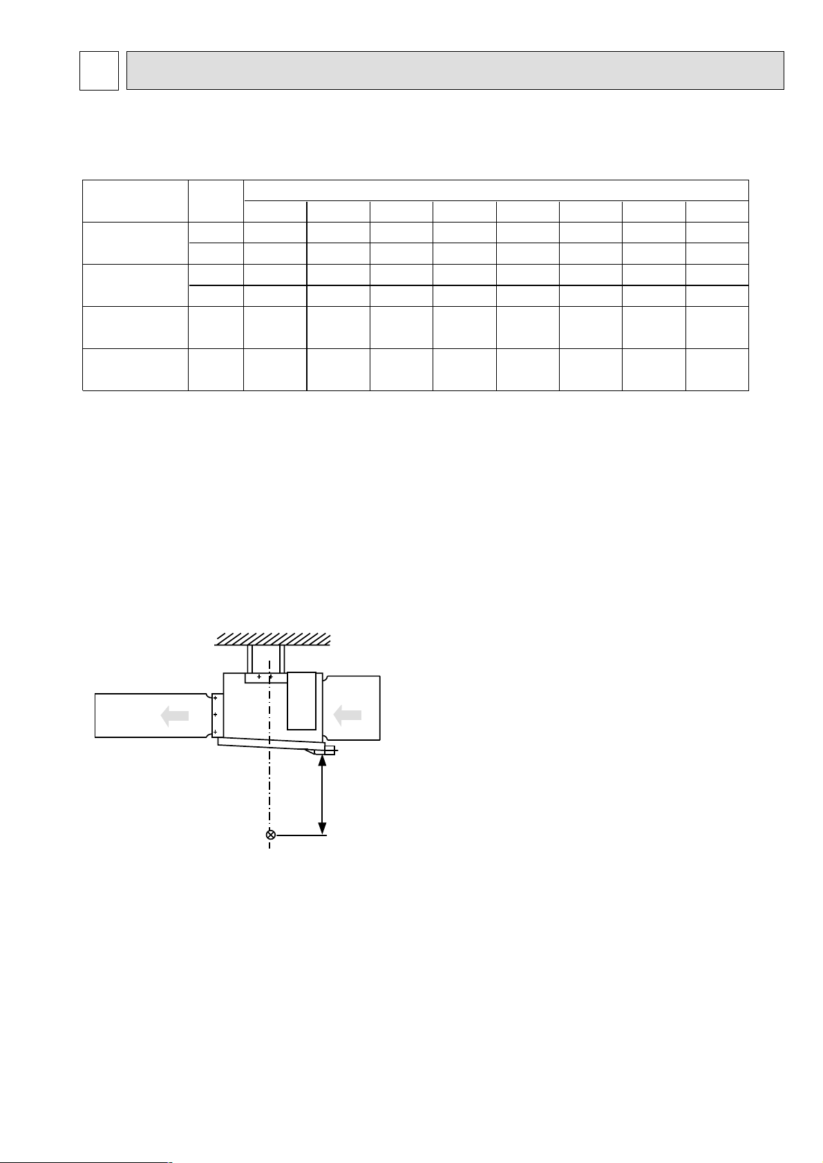
Page 26

26
9-5. HOW TO CHECK THE PARTS
PEA-RP200GA PEA-RP250GA
PEA-RP400GA PEA-RP500GA
Parts name Check points
Disconnect the connector then measure the resistance using a tester.
(Surrounding temperature 10:~30:)
(Refer to the thermistor)
Room temperature
thermistor (TH1)
Pipe temperature
thermistor/liquid (TH2)
Condenser/evaporator
temperature thermistor
(TH5)
Normal
4.3k"~9.6k
"
Abnormal
Open or short
Thermal protector trip temperature
135±5ûC :open
86±15ûC :close
¥PEA-RP200/250GA
Thermal protector trip temperature
150±5ûC :open
96±15ûC :close
¥PEA-RP400/500GA
THERMO
W
ZY
ab
U
X
V
THERMO
Normal
19.9
Ω
25.1
Ω
PEA-RP
200/250GA
Red-White / White-Blue / Red-Blue
Red-White / White-Blue / Red-Blue
Red-White / White-Blue / Red-Blue
Red-White / White-Blue / Red-Blue
Abnormal
Open or short
Hi
Lo
34.2
Ω
PEA-RP
400GA
25.2
Ω
PEA-RP
500GA
Measure the resistance value across the terminals with a multimeter. (Winding
temperature 20 ûC)
(LO)
(LO)
(HI)
(HI)
U2
U1
V1
V1
W1
W2
(LO)
(HI)
Black marking
Black marking
Black marking
Yellow
Blue
Red
Red
Blue
Yellow
White
White
0
10
20
30
40
50
-20 -10 0 10 20 30 40 50
< Thermistor for lower temperature >
Temperature (:)
Resistance (K")
<Thermistor Characteristic graph>
•Room temperature thermistor(TH1)
•Pipe temperature thermistor/liquid(TH2)
•Condenser/Evaporator temperature
thermistor(TH5)
Thermistor R
0=15k' ±3%
Fixed number of B=3480 ± 2%
Rt=15exp { 3480( ) }
0
: 15k'
10: 9.6k'
20: 6.3k'
25: 5.2k'
30: 4.3k'
40: 3.0k'
Thermistor for
lower temperature
1
273+t
1
273
Page 27

27
9-6. TEST POINT DIAGRAM
9-6-1. Power board
PEA-RP200GA PEA-RP250GA
PEA-RP400GA PEA-RP500GA
CNSK
Connect to the indoor controller board
(CNDK)
Between
11
to 33220-240V AC
CN2S
Connect to the indoor controller board (CN2D)
Between
11
to
33
12.6-13.7V DC (Pin11(+))
Page 28

28
9-6-2. Indoor controller board
PEA-RP200GA PEA-RP250GA
PEA-RP400GA PEA-RP500GA
FAN
Fan motor output
CNP
Drain-pump output
(DP)
(220~240V AC)
CNC
Dew prevention
heater (H2)
(220~240V AC)
CNDK
Connect to the indoor
power board (CNSK)
(220~240V AC)
FUSE
(6.3A 250V)
CND
Power
supply input
(220~240V AC)
SWE
Emergency operation
SW2
Capacity setting
SW1
Model setting
CN2L
Connector
(LOSSNAY)
CN51
Centrally control
CN6V
Vane motor output
(MV)
CN90
Connect to the
wireless remote
controller board
(CNB)
CN31
Drain sensor (DS)
CN29
Condenser/evaporator
temperature thermistor
(TH5)
CN21
Pipe temperature
thermistor/Liquid
(TH2)
CN20
Room temperature
thermistor (TH1)
CN22
Remote controller
connecting wire
(10.4~14.6V DC)
LED3
Transmission
(Indoor/outdoor)
LED2
Power supply
(R.B)
LED1
Power supply
(I.B)
CN2D
Connector to the indoor
power board (CN2S)
(12.5~13.7V DC)
CN3C
Transmission
(Indoor/outdoor)
(0~24V DC)
}
}
Non polarity
+
–
+
–
CN41
Connector
(HA terminal-A)
Page 29

29
9-7. FUNCTIONS OF DIP SWITCH AND JUMPER WIRE
Each function is controlled by the dip switch and the jumper wire on control p.c. board.
(Marks in the table below) Jumper wire ( : Short : Open)
Jumper wire
SW1
SW2
JP1
JP3
Functions
Model
settings
Capacity
settings
Unit type
setting
Indoor
controller
board type
setting
Setting by the dip switch and jumper wire
PEA-RP200/250 PEA-RP400/500
JP3
5432
ON
OFF
1
1
Without TH5
Indoor controller board type
5432
ON
OFF
5432
ON
OFF
Model
With TH5
Factory shipment
Service parts
JP1
1
Remarks
There is no jumper (JP1) because these models
have the cond./eva. temperature thermistor (TH5).
Page 30

30
10 SERVICE DATA (PARTS NAME)
Control box
Drain pan
Drain pipe connection
(R1)
Fan motor
Sirocco fan
Suspension bracket
Special washer
Liquid pipe thermistor
(TH2)
2-phase
pipe
thermistor
(TH5)
Strainer
Strainer
Heat exchanger
Liquid pipe
Gas pipe
Inlet thermistor
(TH1)
Drain pan
PEA-RP200/250GA
Page 31

31
PEA-RP400/500GA
Suspension bracket
Special
washer
Drain pipe connection
(R1)
Control box
Sirocco fan
Fan motor
No.1
Inlet thermistor
(TH1-1)
No.2 Gas pipe
No.2 Liquid pipe
2-phase pipe
thermistor
(TH5-1)
No.1 Gas pipe
No.1 Liquid pipe
Drain pan
No.2
Inlet thermistor
(TH1-2)
2-phase pipe
thermistor
(TH5-2)
No.2 Strainer
Strainer
Drain pan
Liquid pipe thermistor
(TH2-2)
Heat exchanger
No.1 Strainer
Liquid pipe thermistor
(TH2-1)
Strainer
Page 32

32
A
Ferrite core
Power supply board
Control board
I/D
POWER BOARD
I/D
CONTROLLER BOARD
Lo
52F
Hi
52F
51F
X1
FB
view A
L2 NL3L1
TB2
TB4TB5
12 S2S1 S3
Relay
SNB
board
Magnetic contactor
(Fan motor Lo speed)
Magnetic contactor
(Fan motor Hi speed)
Terminal block for
remote controller
Terminal block for
outdoor/indoor control
wiring connection
Power supply
terminal block
PEA-RP200/250GA
Page 33

33
PEA-RP400/500GA
view A
Control board
(No.2 unit)
SNB board
Magnetic
contactor
Control board
(No.1 unit)
A
Relay
Ferrite core Ferrite core
FB11
FB21
I/D
POWER BOARD
(NO.2)
52F
I/D
POWER BOARD
(NO.1)
51F
TB2
X1
X2
Power supply
terminal block
Control board
(No.1 unit)
FB12
I/D
CONTROLLER BOARD
(NO.1)
TB4-1 TB5TB4-2
Terminal block for
outdoor/indoor control
wiring connection
(No.1 unit)
FB22
I/D
CONTROLLER BOARD
(NO.2)
Terminal block for
outdoor/indoor control
wiring connection
(No.2 unit)
Control board
(No.2 unit)
Terminal block for
remote controller
Page 34

New publication, effective July 2007.
Specifications subject to change without notice.
HWE07080
Printed in Japan
 Loading...