

Mitsubishi Electric PEA-RP170, PEA-RP200 WHA Installation Manual
Air-Conditioners
INDOOR UNIT
PEA-RP170,200 WHA
GB
INSTALLATION MANUAL
For safe and correct use, please read this installation manual thoroughly before installing the air-conditioner unit.
3
3.2
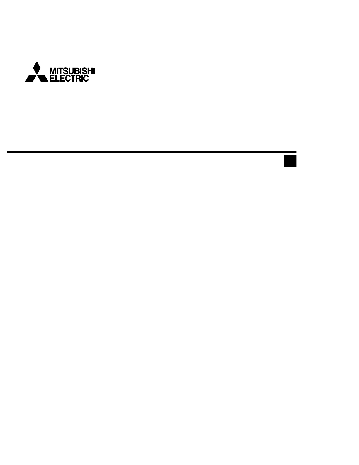
[Fig. 3.2.1]
4
4.1
[Fig. 4.1.1]
A Unit body
B Lifting machine
C Nuts (field supply)
D Washers (accessory)
E M10 hanging bolt (field supply)
5
5.3
[Fig. 5.1.1] [Fig. 5.1.2] [Fig. 5.3.1]
5.1
6
6.2
[Fig. 6.2.1]
2
A Center of gravity
A Indoor unit’s bottom surface
C
D
C
E
D
A Air inlet B Refrigerant piping (liquid)
C Refrigerant piping (gas) D Control box
E Drain pipe F Air outlet
200
~
300
150~200
50
50
1350
730
450
470
more than 20
30
±
10
more than 20
more than 100
60
23 1324 23
371250
1100
1100800
1034
B
C
D
A
AE
Keep the service space for the maintenance from
the bottom when the heat exchanger is cleaned.
701494
235
1034 1324
A
A
B
A
165 52
100 244
30
424
A
B
E
C
D
F
A Access door
B Electrical parts box
C Air inlet
D Air outlet
E Ceiling surface
3
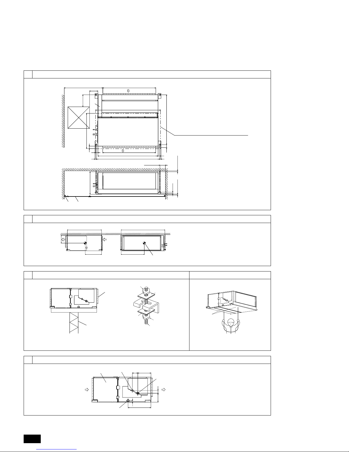
A Cut here
B Remove brazed cap
7
[Fig. 7.1.1]
7.1
7.2
[Fig. 7.1.3]
A
[Fig. 7.1.2]
A Cool by a wet cloth
20
20
20
20
A
B
C
E
D
F
G
H
I
J
K
K
J
L
E
A Thermal insulation tubing (small)
B Caution:
Pull out the thermal insulation on the refrigerant piping
at the site, braze the piping, and replace the insulation
in its original position.
Take care to ensure that condensation does not form on
exposed copper piping.
C Refrigerant piping (liquid)
D Refrigerant piping (gas)
E Main body
F Thermal insulation tubing (large)
G Site refrigerant piping
H Ensure that there are no gaps between the insulation
and the main body.
I Thermal insulation tubing (small) (supplied) 1
J Ties (large) (supplied) 4
K Ensure that there is no gap here. Place join upwards.
L Thermal insulation tubing (medium) (supplied) 2
M Thermal insulation
N Pull
O Flared pipe end
P Wrap with damp cloth
Q Return to original position
R Ensure that there is no gap here.
[Fig. 7.2.1]
A
B 1
C
C
C
D 2
E
A Downward slope 1/100 or more
B Drain hose (Accessory)
C Indoor unit
D Collective piping
E Maximize this length to approx. 10 cm
[Fig. 7.2.2]
A Indoor unit
B Insulation pipe (short) (accessory)
C Tie band (accessory)
D Band fixing part
E Insertion margin
F Drain hose (accessory)
G Drain pipe (O.D. ø32 PVC TUBE, field supply)
H Insulating material (field supply)
I Max.145 ± 5 mm
D
E
H
G
I
F
B
C
525
A
M
M
Q
R
P
O
N
4
8
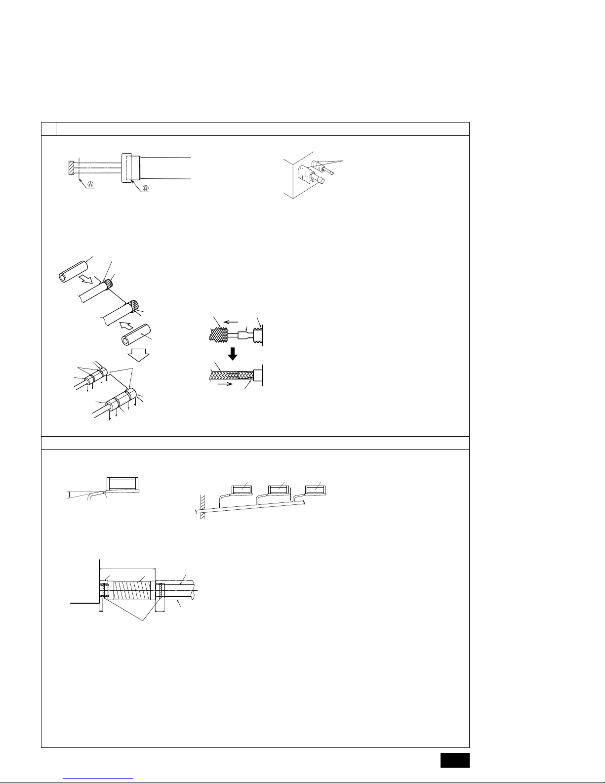
[Fig. 8.0.1]
9
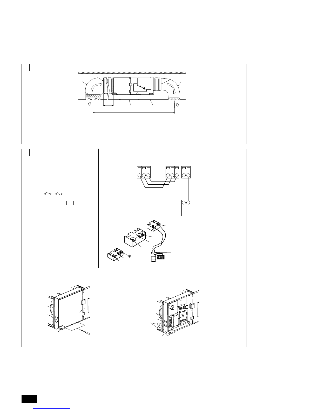
9.1
[Fig. 9.1.1] [Fig. 9.2.1]
A Switch 16 A
B Overcurrent protection 16 A
C Indoor unit
9.2
A Air inlet B Air filter (supplied at site)
C Duct D Canvas duct
E Access door F Ceiling
G Ensure sufficient length to prevent short cycling
H Air outlet I Keep duct-work length 850 mm or more
A Non-polarized
B TB15
C Remote Controller
D TB4
[Fig. 9.2.2]
B
G
E
F
H
A
I
C
C
D
D
AB
C
9.3
A Ter minal bed box
B Knockout hole
C RemoveA Screw holding cover (2pcs)
B Cover
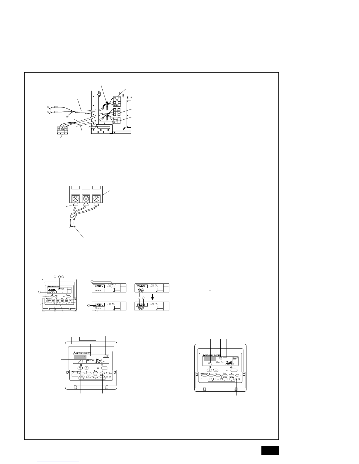
[Fig. 9.3.1] [Fig. 9.3.2]
A
B
B
C
A
A Ter minal block for indoor
transmission cable
B Ter minal block for outdoor
transmission cable
C Remote controller
A
C
TB4 TB15
B
S1 S2 S3 S1 S2 S3 21
2
S3
S2
S1
A
B
D
1
DC10~13V
AB
12
L
N
C
5
I Power source terminal bed
J Ter minal bed for indoor transmission
K Ter minal bed for remote controller
L To 1-phase power source
M Transmission line
N Ter minal bed for outdoor transmission line
O Transmission line to the remote controller
A Ter minal bed
B Round terminal
C Transmission cable (polar)
[Fig. 9.4.1]
[Fig. 9.3.4]
9.4
S2 S3S1
A
B
C
PAR-21MAA
ON/OFF
FILTER
CHECK
OPERATION
CLEAR
TEST
TEMP.
MENU
BACK DAY
MONITOR/SET
CLOCK
ON/OFF
A
B
DC
G
E
F
4
1
213 4
1 2
[Fig. 9.4.2] [Fig. 9.4.3]
˚C
˚C
SIMPLE
PAR-21MAA
ON/OFF
FILTER
CHECK
OPERATION
CLEAR
TEST
TEMP.
MENU
BACK DAY
MONITOR/SET
CLOCK
ON/OFF
TEST RUN
COOL, HEAT
A
FCEDB
M
IH G
˚C
˚C
SIMPLE
PAR-21MAA
ON/OFF
FILTER
CHECK
OPERATION
CLEAR
TEST
TEMP.
MENU
BACK DAY
MONITOR/SET
CLOCK
ON/OFF
B
C
A
E D
A ON/OFF button
B Test run display
C Indoor temperature liquid line
temperature display
D ON/OFF lamp
E Po wer display
A CHECK button
B Refrigerant address
C TEMP. button
D IC: Indoor unit
OC: Outdoor unit
E Check code
F Error code display
Test run remaining time display
G Set temperature button
H Mode selection button
I Fan speed button
M TEST button
A Filter button (<Enter> button)
B TEST button
C Set Time button
D Timer On/Off button (Set Day button)
E Mode selection button
F Set temperature button
G Timer Menu button (Monitor/Set button)
⁄ Mode number
⁄ Setting number
⁄ Refr igerant address
⁄ Unit number
1
2
3
4
I
J
F
G
E
L
N
12
L
S3
S2
S1
S3
S2
S1
K
H
O
N
M
L
N
E Use PG bushing to keep the weight of the cable and external force from being
applied to the power supply terminal connector. Use a cable tie to secure the
cable.
Wind the wire around the cable strap once to keep it from being pulled out.
F Power source wiring
G Tensile force
H Use ordinary bushing
[Fig. 9.3.3]
 Loading...