

Mitsubishi PEA-RP125, PEAD-RP71JAQ, PEA-RP140GAA Operation Manual
Air-Conditioners
PEA-RP100, 125, 140GAA
English
OPERATION MANUAL
For safe and correct use, please read this operation manual thoroughly before operating the air-conditioner unit.
FOR USER
English
<ORIGINAL>
2
Contents
s Before operating the unit, make sure you read all the “Safety
precautions”.
s “Safety precautions” lists important points about safety. Please
be sure to follow them.
Symbols used in the text
Warning:
Describes precautions that should be observed to avoid the risk of
injury or death to the user.
Caution:
Describes precautions that should be observed to prevent damage
to the unit.
Symbols used in the illustrations
: Indicates an action that must be avoided.
: Indicates that important instructions must be followed.
: Indicates a part which must be grounded.
: Beware of electric shock. (This symbol is displayed on the main unit
label.) <Color: yellow>
Warning:
Carefully read the labels affixed to the main unit.
1.1.Installation
1. Safety Precautions
1. Safety Precautions ................................................................ 2
2. Parts Names .......................................................................... 3
3. Screen Configuration............................................................. 6
4. Setting the Day of the Week and Time .................................. 6
5. Operation............................................................................... 6
6. Timer ..................................................................................... 8
7. Other Functions ................................................................... 11
8. Function Selection ............................................................... 12
9. Emergency Operation for Wireless
Remote-controller (option) .................................................. 16
10. Trouble Shooting ................................................................ 17
Note:
The phrase “Wired remote controller” in this operation manual refers only to the PAR-21MAA. If you need any information for the PAR-30MAA, please
refer to the instruction book included in PAR-30MAA box.
ss
ss
s After you have read this manual, keep it and the Installation Manual
in a safe place for easy reference whenever a question arises. If
the unit is going to be operated by another person, make sure
that this manual is given to him or her.
Warning:
• The unit should not be installed by the user. Ask the dealer or an
authorized company to install the unit. If the unit is installed improperly, water leakage, electric shock or fire may result.
• Use only accessories authorized by Mitsubishi Electric and ask
your dealer or an authorized company to install them. If accessories are installed improperly, water leakage, electric shock or fire
may result.
• The Installation Manual details the suggested installation method.
Any structural alteration necessary for installation must comply
with local building code requirements.
• Do not use refrigerant other than the type indicated in the manuals provided with the unit and on the nameplate.
- Doing so may cause the unit or pipes to burst, or result in explosion
or fire during use, during repair, or at the time of disposal of the unit.
- It may also be in violation of applicable laws.
- MITSUBISHI ELECTRIC CORPORATION cannot be held responsi-
ble for malfunctions or accidents resulting from the use of the wrong
type of refrigerant.
•Never repair the unit or transfer it to another site by yourself. If
repair is performed improperly, water leakage, electric shock or
fire may result. If you need to have the unit repaired or moved,
consult your dealer.
• The appliance is not intended for use by young children or infirm
persons without supervision.
•Young children should be supervised to ensure that they do not
play with the appliance.
1) Outdoor unit
Warning:
• The outdoor unit must be installed on a stable, level surface, in
a place where there is no accumulation of snow, leaves or
rubbish.
• Do not stand on, or place any items on the unit. You may fall
down or the item may fall, causing injury.
Caution:
The outdoor unit should be installed in a location where air and
noise emitted by the unit will not disturb the neighbours.
2) Indoor unit
Warning:
The indoor unit should be securely installed. If the unit is loosely
mounted, it may fall, causing injury.
3) Remote controller
Warning:
The remote controller should be installed in such a way that
children cannot play with it.
4) Drain hose
Caution:
Make sure that the drain hose is installed so that drainage can go
ahead smoothly. Incorrect installation may result in water leakage,
causing damage to furniture.
5) Power line, fuse or circuit breaker
Warning:
•
Make sure that the unit is powered by a dedicated line. Other
appliances connected to the same line could cause an overload.
• Make sure that there is a main power switch.
• Be sure to adhere to the unit’s voltage and fuse or circuit
breaker ratings. Never use a piece of wire or a fuse with a
higher rating than the one specified.
6) Grounding
Caution:
• The unit must be properly grounded. Never connect the
grounding wire to a gas pipe, water pipe, lightning conductor
or telephone grounding wire. If the unit is not grounded
properly, electric shock may result.
• Check frequently that the ground wire from the outdoor unit is
properly connected to both the unit’s ground terminal and the
grounding electrode.
3
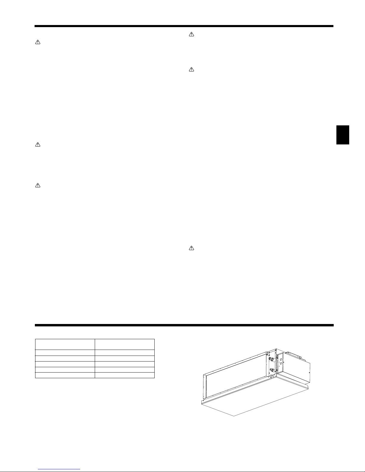
2. Parts Names
■ Indoor Unit
PEA-RP·GAA
Fan steps 2 steps
Vane –
Louver –
Filter –
Filter cleaning indication –
1.2. During operation
Caution:
• Do not use any sharp object to push the buttons, as this may
damage the remote controller.
• Do not twist or tug on the remote controller cord as this may
damage the remote controller and cause malfunction.
•Never remove the upper case of the remote controller. It is
dangerous to remove the upper case of the remote controller
and touch the printed circuit boards inside. Doing so can result
in fire and failure.
•Never wipe the remote controller with benzene, thinner,
chemical rags, etc. Doing so can result in discoloration and
failure. To remove heavy stains, soak a cloth in neutral detergent mixed with water, wring it out thoroughly, wipe the stains
off, and wipe again with a dry cloth.
•Never block or cover the indoor or outdoor unit’s intakes or
outlets. Tall items of furniture underneath the indoor unit, or
bulky items such as large boxes placed close to the outdoor
unit will reduce the unit’s efficiency.
Warning:
• Do not splash water over the unit and do not touch the unit
with wet hands. An electric shock may result.
• Do not spray combustible gas close to the unit. Fire may result.
• Do not place a gas heater or any other open-flame appliance
where it will be exposed to the air discharged from the unit.
Incomplete combustion may result.
Warning:
• Do not remove the front panel or the fan guard from the
outdoor unit when it is running. You could be injured if you
touch rotating, hot or high-voltage parts.
• Never insert fingers, sticks etc. into the intakes or outlets,
otherwise injury may result, since the fan inside the unit
rotates at high speed. Exercise particular care when children
are present.
• If you detect odd smells, stop using the unit, turn off the power
switch and consult your dealer. Otherwise, a breakdown,
electric shock or fire may result.
• When you notice exceptionally abnormal noise or vibration,
stop operation, turn off the power switch, and contact your
dealer.
• Do not over-cool. The most suitable inside temperature is one
that is within 5°C of the outside temperature.
• Do not leave handicapped people or infants sitting or standing
in the path of the airflow from the air-conditioner. This could
cause health problems.
Caution:
• Do not direct the airflow at plants or caged pets.
•Ventilate the room frequently. If the unit is operated continuously in a closed room for a long period of time, the air will
become stale.
In case of failure
Warning:
•Never remodel the air conditioner. Consult your dealer for any
repair service. Improper repair work can result in water
leakage, electric shock, fire, etc.
• If the remote controller displays an error indication, the air
conditioner does not run, or there is any abnormality, stop
operation and contact your dealer. Leaving the unit as it is
under such conditions can result in fire or failure.
• If the power breaker is frequently activated, get in touch with
your dealer. Leaving it as it is can result in fire or failure.
• If the refrigeration gas blows out or leaks, stop the operation of
the air conditioner, thoroughly ventilate the room, and contact
your dealer. Leaving the unit as it is can result in accidents due
to oxygen deficiency.
When the air conditioner is not to be used for a long time
• If the air conditioner is not to be used for a long time due to a
seasonal change, etc., run it for 4 - 5 hours with the air blowing
until the inside is completely dry. Failing to do so can result in
the growth of unhygienic, unhealthy mold in scattered areas
throughout the room.
• When it is not to be used for an extended time, keep the [power
supply] turned OFF.
If the power supply is kept on, several watts or several tens of
watts will be wasted. Also, the accumulation of dust, etc., can
result in fire.
• Keep the power switched ON for more than 12 hours before
starting operation. Do not turn the power supply OFF during
seasons of heavy use. Doing so can result in failure.
1.3. Disposing of the unit
Warning:
When you need to dispose of the unit, consult your dealer. If pipes
are removed incorrectly, refrigerant (fluorocarbon gas) may blow
out and come into contact with your skin, causing injury. Releasing
refrigerant into the atmosphere also damages the environment.
■ PEA-RP·GAA
Ceiling Concealed
1. Safety Precautions
4
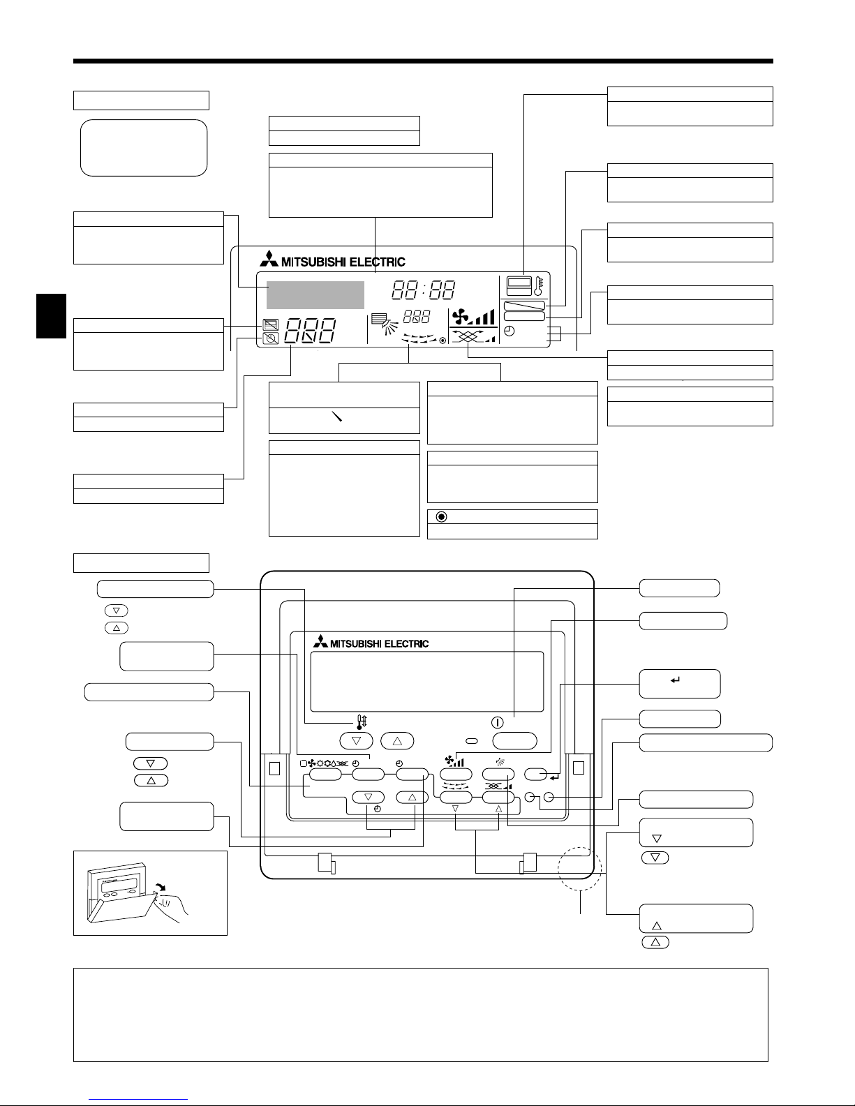
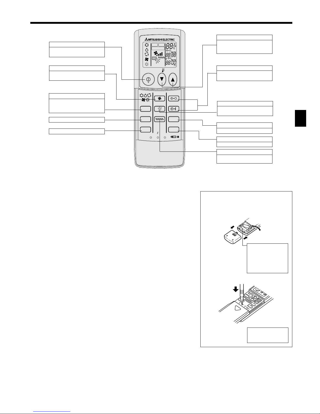
■ Wired Remote-Controller (PAR-21MAA option)
Display Section
For purposes of this explanation,
all parts of the display are shown
as lit. During actual operation, only
the relevant items will be lit.
˚F˚C
˚F˚C
ERROR CODE
AFTER
TIMER
TIME SUN MON TUE WED THU FRI SAT
ON
OFF
Hr
AFTER
FILTER
FUNCTION
ONLY1Hr.
WEEKLY
SIMPLE
AUTO OFF
Identifies the current operation
Shows the operating mode, etc.
* Multilanguage display is sup-
ported.
“Centrally Controlled” indicator
Indicates that operation of the remote controller has been prohibited by a master controller.
“Timer is Off” indicator
Indicates that the timer is off.
Temperature Setting
Shows the target temperature.
Day-of-Week
Shows the current day of the week.
Time/Timer Display
Shows the current time, unless the simple or Auto Off
timer is set.
If the simple or Auto Off timer is set, shows the time
remaining.
“Sensor” indication
Displayed when the remote controller
sensor is used.
“Locked” indicator
Indicates that remote controller buttons have been locked.
“Clean The Filter” indicator
Comes on when it is time to clean the
filter.
Timer indicators
The indicator comes on if the corresponding timer is set.
Up/Down Air Direction indicator
The indicator shows the direction of the outcoming airflow.
“One Hour Only” indicator
Displayed if the airflow is set to
weak and downward during COOL
or DRY mode. (Operation varies
according to model.)
The indicator goes off after one
hour, at which time the airflow direction also changes.
Room Temperature display
Shows the room temperature. The room
temperature display range is 8–39°C.
The display flashes if the temperature
is less than 8 °C or 39 °C or more.
Louver display
Indicates the action of the swing louver.
Does not appear if the louver is stationary.
(Power On indicator)
Indicates that the power is on.
Fan Speed indicator
Shows the selected fan speed.
Ventilation indicator
Appears when the unit is running in
Ventilation mode.
Operation Section
PAR-21MAA
ON/OFF
FILTER
CHECK
OPERATION
CLEAR
TEST
TEMP.
MENU
BACK DAY
MONITOR/SET
CLOCK
ON/OFF
Set Temperature buttons
Down
Up
Timer Menu button
(Monitor/Set button)
Mode button (Return button)
Set Time buttons
Back
Ahead
Timer On/Off button
(Set Day button)
Opening the
door.
ON/OFF button
Fan Speed button
Filter button
(<Enter> button)
Test Run button
Check button (Clear button)
Airflow Up/Down button
Louver button
(
Operation button)
To preceding operation
number.
Ventilation button
(
Operation button)
To next operation
number.
2. Parts Names
Built-in temperature sensor
Note:
● “PLEASE WAIT” message
This message is displayed for approximately 3 minutes when power is supplied to the indoor unit or when the unit is recovering from a power failure.
● “NOT AVAILABLE” message
This message is displayed if a button is pressed to operate a function that the indoor unit does not have.
If a single remote controller is used to simultaneously operate multiple indoor units that are different models, this message will not be displayed if
any of the indoor units is equipped with the function.
5
1
2
3
■ Wireless Remote-Controller (option)
2. Parts Names
■ When using the wireless remote controller, point it towards the receiver on the indoor unit.
■ If the remote controller is operated within approximately two minutes after power is supplied
to the indoor unit, the indoor unit may beep twice as the unit is performing the initial automatic check.
■ The indoor unit beeps to confirm that the signal transmitted from the remote controller has
been received. Signals can be received up to approximately 7 meters in a direct line from
the indoor unit in an area 45° to the left and right of the unit. However, illumination such as
fluorescent lights and strong light can affect the ability of the indoor unit to receive signals.
■ If the operation lamp near the receiver on the indoor unit is flashing, the unit needs to be
inspected. Consult your dealer for service.
■ Handle the remote controller carefully! Do not drop the remote controller or subject it to
strong shocks. In addition, do not get the remote controller wet or leave it in a location with
high humidity.
■ To avoid misplacing the remote controller, install the holder included with the remote controller on a wall and be sure to always place the remote controller in the holder after use.
Battery installation/replacement
1. Remove the top cover, insert two AAA batteries, and then install the top cover.
Top cover
2. Press the Reset button.
CLOCK
CHECK
RESET
SET
TEST RUN
MODE
FAN
VANE
LOUVER
min
h
AUTO START
AUTO STOP
ON/OFF
TEMP
NOT AVAILABLE
MODEL SELECT
TEST RUN
CHECK
ON/OFF button
Pushing button starts operation.
Pushing again stops operation.
MODE SELECT button
This button is used to change between auto, cooling, heating and
drying operation modes.
SET TEMPERATURE button
SET TEMPERATURE button sets
and any desired room temperature.
AUTO STOP/AUTO START button
Used for selecting timed starting
or stopping.
h button
Used for setting the current time.
VANE CONTROL button
Used to change the airflow direction.
Tw o AAA batteries
Insert the negative (–)
end of each battery
first. Install the batteries in the correct directions (+, –)!
FAN SPEED button
This button is used to set fan
speed to low, medium or high.
CHECK button
TEST RUN button
min button
Used for setting the current time.
LOUVER button
Used for adjusting the airflow direction.
Press the Reset button
with an object that has
a narrow end.
6
AAA
AAA
CLOCK
CHECK
RESET
SET
TEST RUN
MODE
FAN
VANE
LOUVER
min
h
AUTO START
AUTO STOP
ON/OFF
TEMP
1
2
5
6
3
3
5
6
2
Note:
The day and time will not appear if clock use has been disabled at Function
Selection of remote controller.
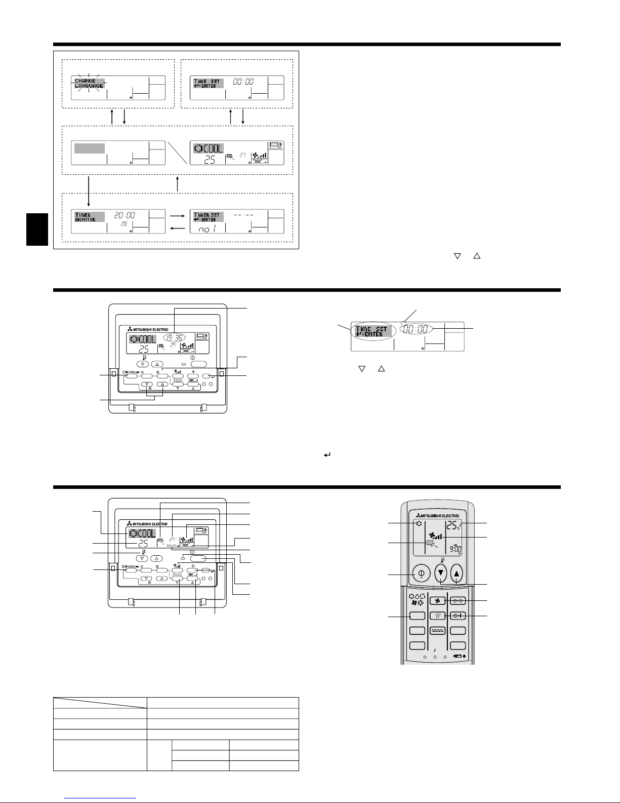
3. Screen Configuration
<Screen Types>
For details on setting the language for the remote controller display, refer
to section 8. Function Selection.
The initial language setting is English.
● Function Selection of remote controller:
Set the functions and ranges available to the remote controller (timer functions, operating restrictions, etc.)
● Set Day/Time: Set the current day of the week or time.
● Standard Control Screens:
View and set the air conditioning system’s operating status
● Timer Monitor: View the currently set timer (weekly timer, sim-
ple timer, or Auto Off timer)
● Timer Setup: Set the operation of any of the timers (weekly
timer, simple timer, or Auto Off timer).
<How to change the screen>
A :Hold down both the Mode button and the Timer On/Off button for 2
seconds.
B :Press the Timer Menu button.
C :Press the Mode (Return) button.
D :Press either of the Set Time buttons ( or ).
˚F˚C
TIMER
MON
OFF
WEEKLY
SUN MON TUE WED THU FRI SAT
WEEKLY
˚F˚C
˚C
TIME SUN
Function Selection of remote controller
Set Day/Time
Standard Control Screens
OFF ON
Timer Monitor Timer Setup
ADC
BC
B
1. Press the or Set Time button A to show display 2.
2. Press the Timer On/Off (Set Day) button 9 to set the day.
* Each press advances the day shown at 3 : Sun → Mon → ... → Fri →
Sat.
3. Press the appropriate Set Time button A as necessary to set the time.
* As you hold the button down, the time (at 4) will increment first in
minute intervals, then in ten-minute intervals, and then in one-hour intervals.
4. After making the appropriate settings at Steps 2 and 3, press the Filter
button 4 to lock in the values.
4. Setting the Day of the Week and Time
Day of the Week &
Time display
˚C
˚C
TIME SUN
PAR-21MAA
ON/OFF
FILTER
CHECK
OPERATION
CLEAR
TEST
TEMP.
MENU
BACK DAY
MONITOR/SET
CLOCK
ON/OFF
2
4
9
1
A
Time Setting
TIME SUN
2
3
4
Day of the Week Setting
Mode
Temperature setting
Fan speed
Airflow up/down
Remote Controller settings
Last operation mode
Last set temperature
Last set fan speed
COOL or DRY
Mode HEAT
FAN
Horiz. outlet
Last setting
Horiz. outlet
5. Operation
˚C
˚C
PAR-21MAA
ON/OFF
FILTER
CHECK
OPERATION
CLEAR
TEST
TEMP.
MENU
BACK DAY
MONITOR/SET
CLOCK
ON/OFF
2
7
2
3
3
8
6
4
5
8
7
1
1
5
6
5.1. Turning ON/OFF
<To Start Operation>
■ Press the ON/OFF button 1.
• The ON lamp 1 and the display area come on.
Note:
● When the unit is restarted, initial settings are as follows.
(option)
(option)
(option)
 Loading...