

Mitsubishi Electric PEA-RP-EA, PEA-RP71EA, PEA-RP100EA, PEA-RP125EA, PEA-RP140EA Installation Manual
Air-Conditioners
PEA-RP·EA
INSTALLATION MANUAL
For safe and correct use, read this manual and the outdoor unit installation manual thoroughly before installing
the air-conditioner unit.
FOR INSTALLER
English
Contents
1. Safety precautions ................................................................................... 2
2. Installation location .................................................................................. 3
3. Installing the indoor unit ........................................................................... 3
4. Installing the refrigerant piping ................................................................. 5
5. Drainage piping work (Fig. 5-1) ................................................................ 6
1. Safety precautions
s Before installing the unit, make sure you read all the “Safety precau-
tions”.
s Please report to or take consent by the supply authority before connec-
tion to the system.
Warning:
Describes precautions that must be observed to prevent danger of injury or
death to the user.
Caution:
Describes precautions that must be observed to prevent damage to the unit.
Warning:
• The unit must not be installed by the user. Ask a dealer or an authorized
technician to install the unit. If the unit is installed incorrectly, water leakage,
electric shock, or fire may result.
• For installation work, follow the instructions in the Installation Manual and
use tools and pipe components specifically made for use with R410A refrigerant. The R410A refrigerant in the HFC system is pressurized 1.6 times the
pressure of usual refrigerants. If pipe components not designed for R410A
refrigerant are used and the unit is not installed correctly, the pipes may burst
and cause damage or injuries. In addition, water leakage, electric shock, or
fire may result.
• The unit must be installed according to the instructions in order to minimize
the risk of damage from earthquakes, typhoons, or strong winds. An incorrectly installed unit may fall down and cause damage or injuries.
• The unit must be securely installed on a structure that can sustain its weight.
If the unit is mounted on an unstable structure, it may fall down and cause
damage or injuries.
• If the air conditioner is installed in a small room, measures must be taken to
prevent the refrigerant concentration in the room from exceeding the safety
limit in the event of refrigerant leakage. Consult a dealer regarding the appropriate measures to prevent the allowable concentration from being exceeded.
Should the refrigerant leak and cause the concentration limit to be exceeded,
hazards due to lack of oxygen in the room may result.
• Ventilate the room if refrigerant leaks during operation. If refrigerant comes
into contact with a flame, poisonous gases will be released.
• All electric work must be performed by a qualified technician according to
local regulations and the instructions given in this manual. The units must be
powered by dedicated power lines and the correct voltage and circuit breakers must be used. Power lines with insufficient capacity or incorrect electrical work may result in electric shock or fire.
6. Electrical work .......................................................................................... 6
7. Duct work (Fig. 7-1) ............................................................................... 10
8. Test run .................................................................................................. 10
9. Easy maintenance function .................................................................... 13
After installation work has been completed, explain the “Safety Precautions,” use,
and maintenance of the unit to the customer according to the information in the Operation Manual and perform the test run to ensure normal operation. Both the Installation Manual and Operation Manual must be given to the user for keeping. These
manuals must be passed on to subsequent users.
: Indicates a part which must be grounded.
Warning:
Carefully read the labels affixed to the main unit.
• Use C1220 copper phosphorus, for copper and copper alloy seamless pipes,
to connect the refrigerant pipes. If the pipes are not connected correctly, the
unit will not be properly grounded and electric shock may result.
• Use only specified cables for wiring. The connections must be made securely
without tension on the terminals. If the cables are connected or installed incorrectly, overheating or fire may result.
• The terminal block cover of the outdoor unit must be firmly attached. If the
cover is mounted incorrectly and dust and moisture enter the unit, electric
shock or fire may result.
• When installing or moving the air conditioner, use only the specified refrigerant (R410A) to charge the refrigerant lines. Do not mix it with any other refrigerant and do not allow air to remain in the lines. Air enclosed in the lines can
cause pressure peaks resulting in a rupture and other hazards.
• Use only accessories authorized by Mitsubishi Electric and ask a dealer or
an authorized technician to install them. If accessories are incorrectly installed, water leakage, electric shock, or fire may result.
• Do not alter the unit. Consult a dealer for repairs. If alterations or repairs are
not performed correctly, water leakage, electric shock, or fire may result.
• The user should never attempt to repair the unit or transfer it to another location. If the unit is installed incorrectly, water leakage, electric shock, or fire
may result. If the air conditioner must be repaired or moved, ask a dealer or
an authorized technician.
• After installation has been completed, check for refrigerant leaks. If refrigerant leaks into the room and comes into contact with the flame of a heater or
portable cooking range, poisonous gases will be released.
1.1. Before installation
Caution:
• Do not use the unit in an unusual environment. If the air conditioner is installed in areas exposed to steam, volatile oil (including machine oil), or sulfuric
gas, areas exposed to high salt content such as the seaside, or areas where
the unit will be covered by snow, the performance can be significantly reduced and the internal parts can be damaged.
• Do not install the unit where combustible gases may leak, be produced, flow,
or accumulate. If combustible gas accumulates around the unit, fire or explosion may result.
• Do not keep food, plants, caged pets, artwork, or precision instruments in the
direct airflow of the indoor unit or too close to the unit, as these items can be
damaged by temperature changes or dripping water.
1.2. Before installation (relocation)
Caution:
• Be extremely careful when transporting the units. Two or more persons are
needed to handle the unit, as it weighs 20 kg or more. Do not grasp the packaging bands. Wear protective gloves to remove the unit from the packaging
and to move it, as you can injure your hands on the fins or other parts.
• Be sure to safely dispose of the packaging materials. Packaging materials,
such as nails and other metal or wooden parts may cause stabs or other
injuries.
• Thermal insulation of the drainpipe is necessary to prevent condensation. If
the drainpipe is not properly insulated, condensation will be formed and the
ceiling, floor, or important items may be damaged.
2
• When the room humidity exceeds 80% or when the drainpipe is clogged, water may drip from the indoor unit. Do not install the indoor unit where such
dripping can cause damage. The outdoor unit produces condensation during
the heating operation. Make sure to provide drainage around the outdoor unit
if such condensation is likely to cause damage.
• When installing the unit in a hospital or communications office, be prepared
for noise and electronic interference. Inverters, home appliances, high-frequency medical equipment, and radio communications equipment can cause
the air conditioner to malfunction or breakdown. The air conditioner may also
affect medical equipment, disturbing medical care, and communications equipment, harming the screen display quality.
• Install the drainpipe according to this Installation Manual to ensure proper
drainage. Place thermal insulation on the pipes to prevent condensation. If
the drainpipe is installed incorrectly, water leakage and damage to the ceiling, floor, furniture, or other possessions may result.
• The base and attachments of the outdoor unit must be periodically checked
for looseness, cracks or other damage. If such defects are left uncorrected,
the unit may fall down and cause damage or injuries.
• Do not clean the air conditioner unit with water. Electric shock may result.
• Tighten all flare nuts to specification using a torque wrench. If tightened too
much, the flare nut can break after an extended period and refrigerant can
leak out.
1. Safety precautions
1.3. Before electric work
Caution:
• Be sure to install circuit breakers. If not installed, electric shock may result.
• For the power lines, use standard cables of sufficient capacity. Otherwise, a
short circuit, overheating, or fire may result.
• When installing the power lines, do not apply tension to the cables. If the
connections are loosened, the cables can snap or break and overheating or
fire may result.
1.4. Before starting the test run
Caution:
• Turn on the main power switch more than 12 hours before starting operation.
Starting operation just after turning on the power switch can severely damage the internal parts. Keep the main power switch turned on during the operation season.
• Before starting operation, check that all panels, guards and other protective
parts are correctly installed. Rotating, hot, or high voltage parts can cause
injuries.
• Do not operate the air conditioner without the air filter set in place. If the air
filter is not installed, dust may accumulate and breakdown may result.
2. Installation location
• Be sure to ground the unit. Do not connect the ground wire to gas or water
pipes, lighting rods, or telephone grounding lines. If the unit is not properly
grounded, electric shock may result.
• Use circuit breakers (ground fault interrupter, isolating switch (+B fuse), and
molded case circuit breaker) with the specified capacity. If the circuit breaker
capacity is larger than the specified capacity, breakdown or fire may result.
• Do not touch any switch with wet hands. Electric shock may result.
• Do not touch the refrigerant pipes with bare hands during operation. The
refrigerant pipes are hot or cold depending on the condition of the flowing
refrigerant. If you touch the pipes, burns or frostbite may result.
• After stopping operation, be sure to wait at least five minutes before turning
off the main power switch. Otherwise, water leakage or breakdown may result.
• Select a location so that air can be blown into all corners of the room.
• Avoid locations exposed to outside air.
• Select a location free of obstructions to the airflow in and out of the unit.
• Avoid locations exposed to steam or oil vapour.
• Avoid locations where combustible gas may leak, settle or be generated.
• Avoid installation near machines emitting high-frequency waves (high-frequency
welders, etc.)
• Avoid locations where the airflow is directed at a fire alarm sensor. (Hot air could
trigger the alarm during the heating operation.)
3. Installing the indoor unit
1
3
2
Fig. 3-1
• Avoid places where acidic solutions are frequently handled.
• Avoid places where sulphur-based or other sprays are frequently used.
• Must be installed at least 1.8 m above floor or grade level.
Warning:
The unit must be securely installed on a structure that can sustain its weight.
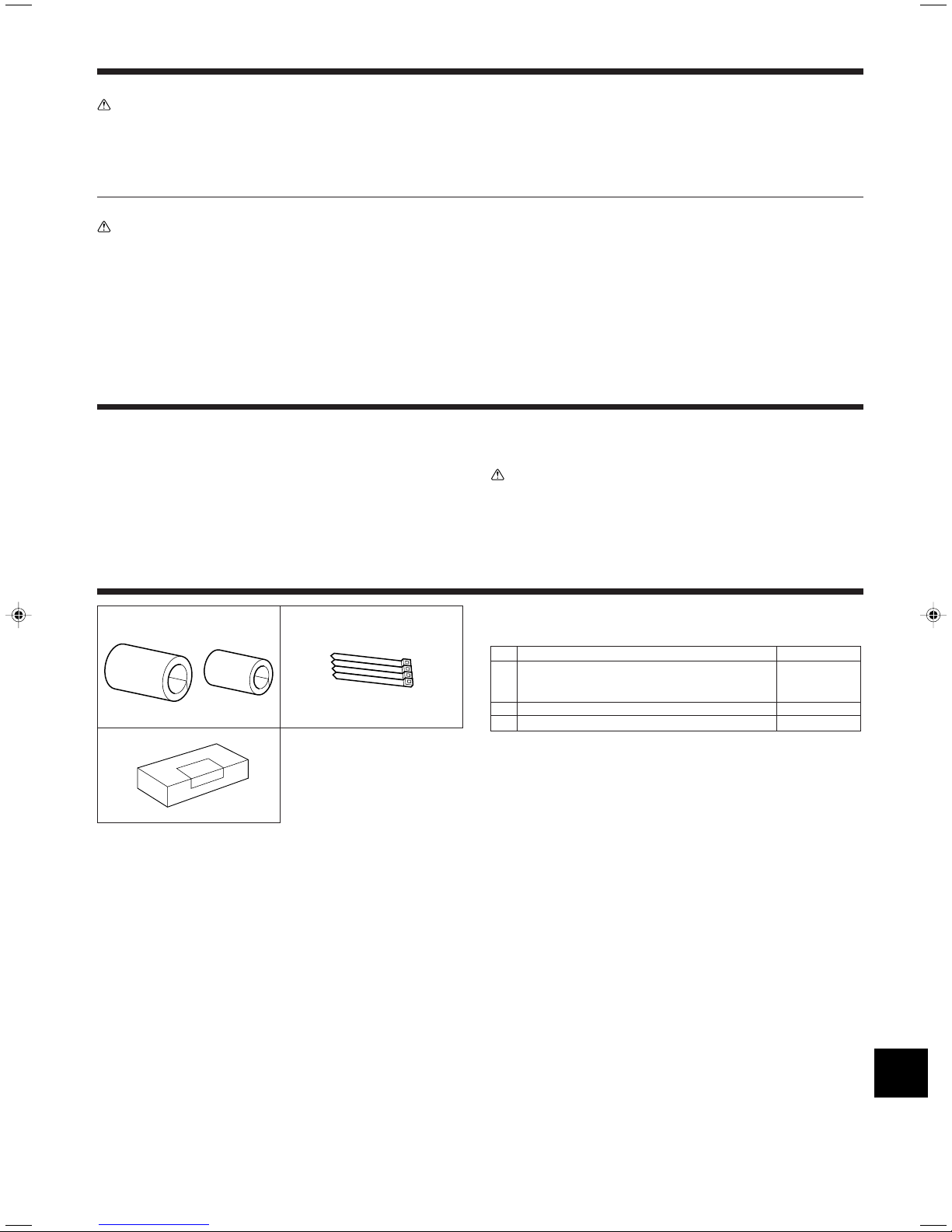
3.1. Check the indoor unit accessories (Fig. 3-1)
The indoor unit is provided with the following accessories.
Accessory name Q’ty
Pipe cover (for refrigerant piping joint)
1 small diameter 1
large diameter 1
2 Band 4
3 Remote controller 1
3
D
W
H
A
B
C
D
200
B
G
E
F
E
C
D
B
A
30
3. Installing the indoor unit
11
11
200
200
21
A
B
D
E
C
600
100
AB
900
300 530
E
F
D
30
100
130
Fig. 3-2
(mm)
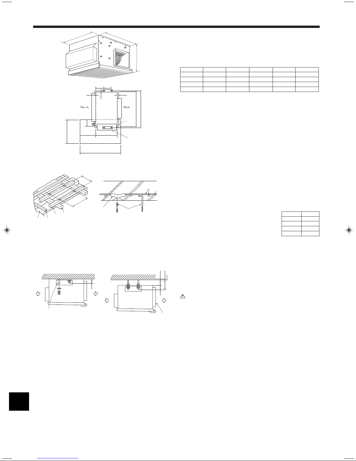
3.2. Unit dimension and service space (Fig. 3-2)
A Air intake
B Air outlet
C Service space
D Drain pan
E Electrical parts box
Models W H D A B
RP71 785 690 428 650 690
RP100 1055 690 428 920 960
RP125 1255 690 428 1120 1160
RP140 1415 690 428 1306 1346
*B : Suspension bolt pitch
(mm)
1
A Ceiling
B Rafter
C Beam
D Roof beam
2
E Use inserts rated at 100-150 kg each
(procure locally)
F Suspension bolts M10 (3/8") (procure
locally)
G Steel reinforcing rod
Fig. 3-3
12
A Washer (procure locally)
B 2 nuts (procure locally)
C Suspension bolt (procure locally)
D Air intake
E Air outlet
F Air intake duct flange
Fig. 3-4
3.3. Suspension structure (Give site of suspension
strong structure) (Fig. 3-3)
• The ceiling work differs according to the construction of the building. Building con-
structors and interior decorators should be consulted for details.
1 Wooden structures
• Use tie beams (single storied houses) or second floor beams
(two story houses) as reinforcing members.
• Wooden beams for suspending air conditioners must be
sturdy and their sides must be at least 6 cm long if the
beams are separated by not more than 90 cm and their
sides must be at least 9 cm long if the beams are separated by as much as 180 cm. The size of the suspension
bolts should be ø10 (3/8"). (The bolts do not come with the
unit.)
2 Ferro-concrete structures
Secure the suspension bolts using the method shown, or use steel or wooden hangers, etc. to install the suspension bolts.
Models B
RP71 690
RP100 960
RP125 1160
RP140 1346
(mm)
3.4. Unit suspension procedures (Fig. 3-4)
Suspend the main unit as shown in the Fig. 3-4.
1 When no air intake duct flange is used.
2 When air intake duct flange is used.
Caution:
• Make sure that the unit is level when installed.
• Work with the protection gloves when you install the unit. (Take care of a
hurt.)
To prevent getting hurt.
4
4. Installing the refrigerant piping
A
A
B
90° ±0.5°
øA
R0.4~R0.8
A
45°±2°
B
4.1. Precautions
4.1.1. For devices that use R407C refrigerant
• Do not use the existing refrigerant piping.
• Do not use crushed, misshapen, or discolored tubing. The inside of the tub-
ing should be clean and free from harmful sulfuric compounds, oxidants,
dirt, debris, oils and moisture.
• Store the piping to be used during installation indoors and keep both ends of
the piping sealed until just before brazing.
• Use ester oil, ether oil or alkylbenzene (small amount) as the refrigerator oil
to coat flares and flange connections.
• Use liquid refrigerant to fill the system.
• Do not use a refrigerant other than R407C.
• Use a vacuum pump with a reverse flow check valve.
• Do not use the tools that are used with conventional refrigerants.
• Do not use a charging cylinder.
• Be especially careful when managing the tools.
• Do not use commercially available dryers.
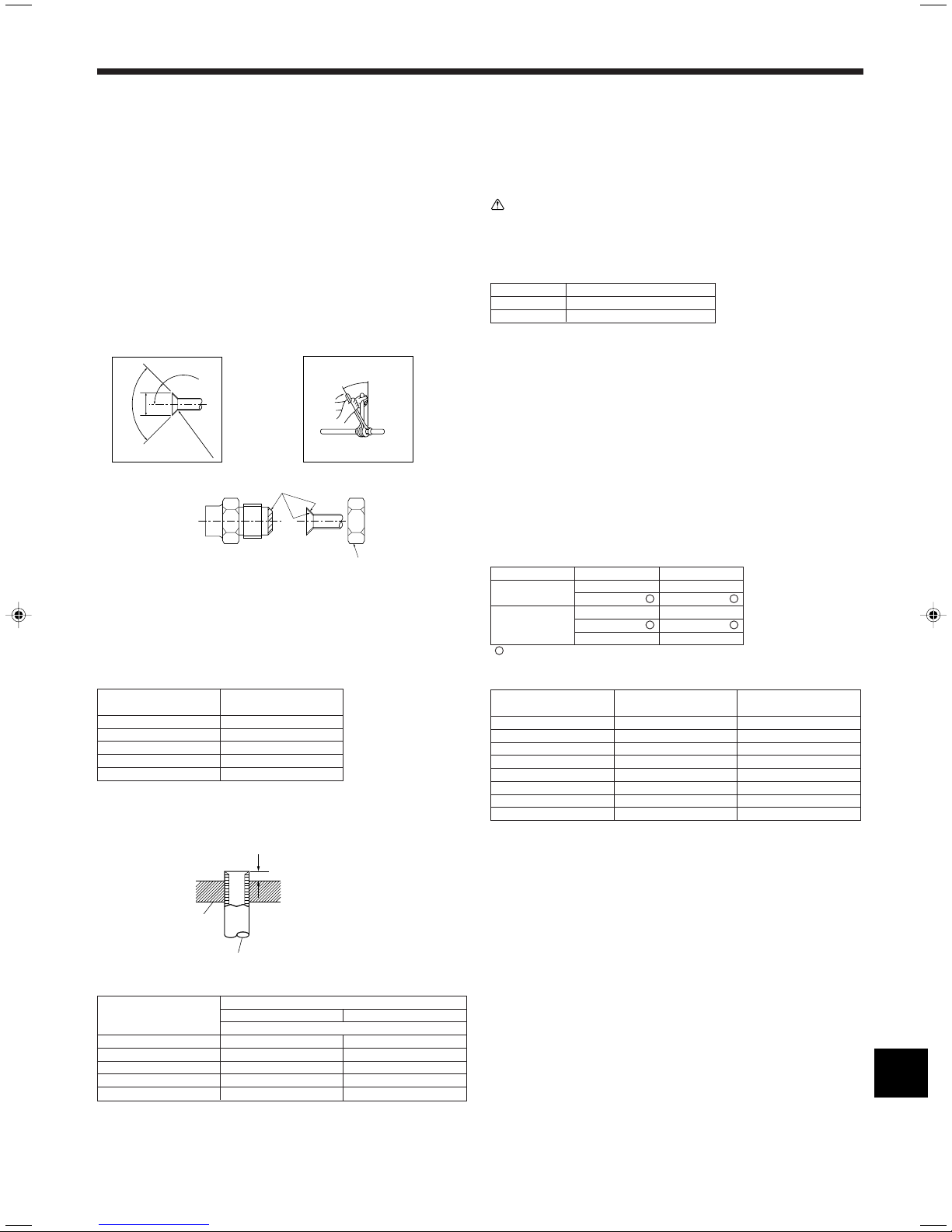
Apply refrigerating machine oil over the entire flare seat surface.
Be sure to only use the flare nuts
that came with the unit.
Fig. 4-1
A Flare cutting dimensions
Copper pipe O.D. Flare dimensions
(mm) øA dimensions (mm)
ø6.35 8.7 - 9.1
ø9.52 12.8 - 13.2
ø12.7 16.2 - 16.6
ø15.88 19.3 - 19.7
ø19.05 23.6 - 24.0
4.1.2. For devices that use R410A refrigerant
• Use ester oil, ether oil, alkylbenzene oil (small amount) as the refrigeration oil
applied to the flared sections.
• Use C1220 copper phosphorus, for copper and copper alloy seamless pipes,
to connect the refrigerant pipes. Use refrigerant pipes with the thicknesses
specified in the table to the below. Make sure the insides of the pipes are
clean and do not contain any harmful contaminants such as sulfuric compounds, oxidants, debris, or dust.
Warning:
When installing or moving the air conditioner, use only the specified refrigerant (R410A) to charge the refrigerant lines. Do not mix it with any other refrigerant and do not allow air to remain in the lines. Air enclosed in the lines can
cause pressure peaks resulting in a rupture and other hazards.
Liquid pipe ø9.52 thickness 0.8 mm
Gas pipe ø15.88 thickness 1.0 mm
• Do not use pipes thinner than those specified above.
RP71-140
4.2. Indoor unit (Fig. 4-1)
• When commercially available copper pipes are used, wrap liquid and gas pipes
with commercially available insulation materials (heat-resistant to 100 °C or more,
thickness of 12 mm or more).
• The indoor parts of the drain pipe should be wrapped with polyethylene foam insu-
lation materials (specific gravity of 0.03, thickness of 9 mm or more).
• Apply thin layer of refrigerant oil to pipe and joint seating surface before tightening
flare nut.
• Use two wrenches to tighten piping connections.
• Use leak detector or soapy water to check for gas leaks after connections are com-
pleted.
• Use refrigerant piping insulation provided to insulate indoor unit connections. Insu-
late carefully following shown below.
• Use correct flare nuts meeting the pipe size of the outdoor unit.
Available pipe size
RP71 RP100, 125, 140
Liquid side
Gas side ø15.88
: Factory flare nut attachment to the heat-exchanger.
B Flare nut tightening torque
Copper pipe O.D. Flare nut O.D. Tightening torque
(mm) (mm) (N·m)
ø6.35 17 14 - 18
ø6.35 22 34 - 42
ø9.52 22 34 - 42
ø12.7 26 49 - 61
ø12.7 29 68 - 82
ø15.88 29 68 - 82
ø15.88 36 100 - 120
ø19.05 36 100 - 120
––
ø9.52
––
––
ø9.52
ø15.88
A Die
B Copper pipe
Fig. 4-2
Copper pipe O.D.
(mm)
ø6.35 (1/4") 0 - 0.5 1.0 - 1.5
ø9.52 (3/8") 0 - 0.5 1.0 - 1.5
ø12.7 (1/2") 0 - 0.5 1.0 - 1.5
ø15.88 (5/8") 0 - 0.5 1.0 - 1.5
ø19.05 (3/4") 0 - 0.5 1.0 - 1.5
Flare tool for R-22·R407C Flare tool for R410A
A (mm)
Clutch type
5
 Loading...