

Mitsubishi Electric PEA-RP, PEA-EA Operation Manual
Air-Conditioners
Indoor unit
PEA-RP·EA
OPERATION MANUAL
For safe and correct use, please read this operation manual thoroughly before operating the air-conditioner unit.
FOR USER
English
Contents
1. Safety Precautions ................................................................ 2
2. Parts Names ......................................................................... 2
3. Screen Configuration ............................................................ 4
4. Setting the Day of the Week and Time .................................. 4
5. Operation .............................................................................. 4
6. Timer ..................................................................................... 6
1. Safety Precautions
s Before installing the unit, make sure you read all the
“Safety Precautions”.
s The “Safety Precautions” provide very important points
regarding safety. Make sure you follow them.
s Please report to or take consent by the supply author-
ity before connection to the system.
Warning:
• The unit must not be installed by the user. Ask the dealer or an
authorized company to install the unit. If the unit is installed improperly, water leakage, electric shock or fire may result.
• Do not stand on, or place any items on the unit.
• Do not splash water over the unit and do not touch the unit with
wet hands. An electric shock may result.
• Do not spray combustible gas close to the unit. Fire may result.
• Do not place a gas heater or any other open-flame appliance where
it will be exposed to the air discharged from the unit. Incomplete
combustion may result.
• Do not remove the front panel or the fan guard from the outdoor
unit when it is running.
Caution:
• Do not use any sharp object to push the buttons, as this may damage the remote controller.
• Never block or cover the indoor or outdoor unit’s intakes or outlets.
7. Other Functions .................................................................... 9
8. Function Selection .............................................................. 10
9. Care and Cleaning .............................................................. 14
10. Trouble Shooting ............................................................... 14
11. Specifications .................................................................... 15
Symbols used in the text
Warning:
Describes precautions that should be observed to prevent danger of
injury or death to the user.
Caution:
Describes precautions that should be observed to prevent damage
to the unit.
Symbols used in the illustrations
: Indicates a part which must be grounded.
• When you notice exceptionally abnormal noise or vibration, stop
operation, turn off the power switch, and contact your dealer.
• Never insert fingers, sticks etc. into the intakes or outlets.
• If you detect odd smells, stop using the unit, turn off the power
switch and consult your dealer. Otherwise, a breakdown, electric
shock or fire may result.
• This air conditioner is NOT intended for use by children or infirm
persons without supervision.
• Young children must be supervised to ensure that they do not play
with the air conditioner.
• If the refrigeration gas blows out or leaks, stop the operation of the
air conditioner, thoroughly ventilate the room, and contact your
dealer.
Disposing of the unit
When you need to dispose of the unit, consult your dealer.
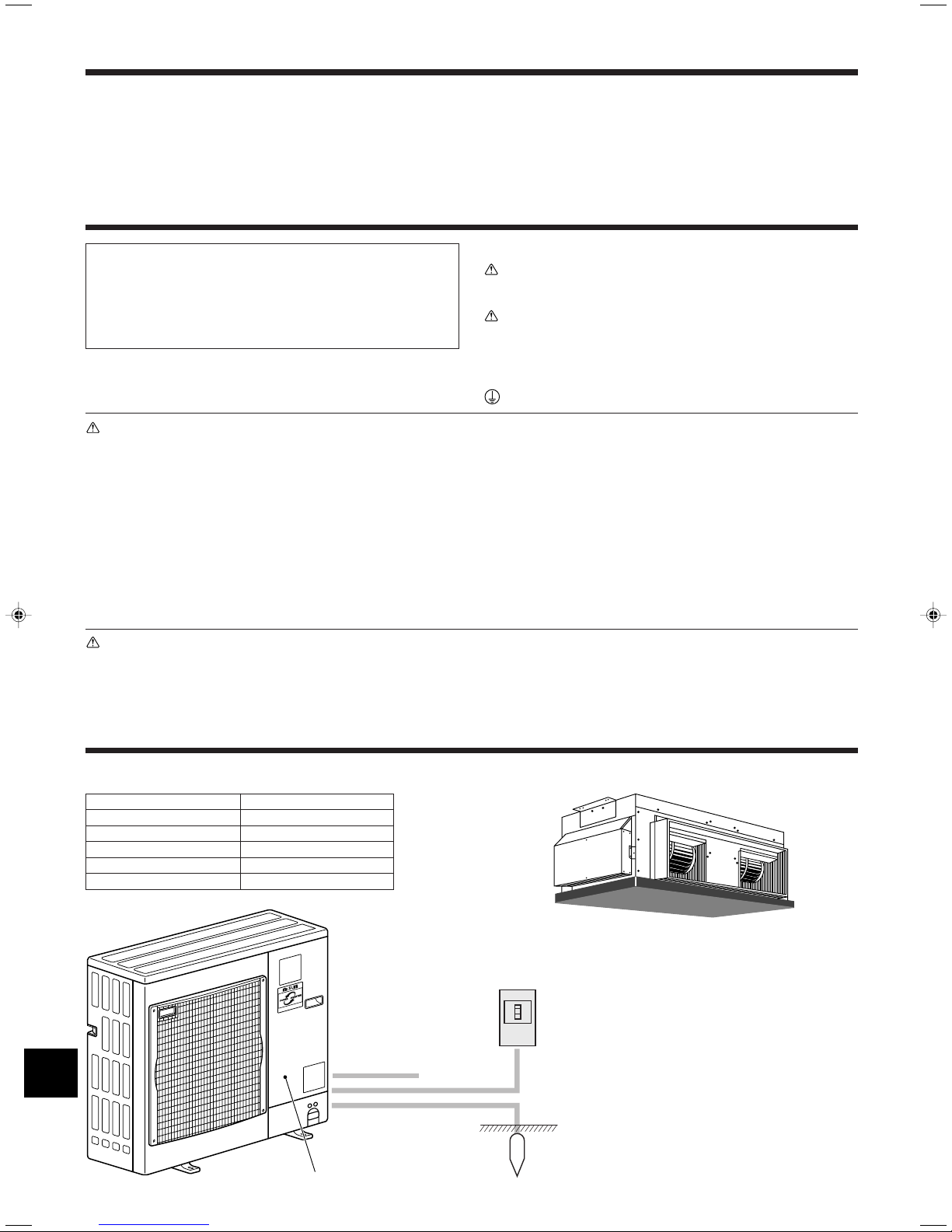
2. Parts Names
■ Indoor Unit
PEA-RP·EA
Fan steps 2 steps
Vane –
Louver –
Filter –
Filter cleaning indication –
■ Outdoor unit
Service Panel
2
■ PEA-RP·EA
Ceiling Concealed
Power
Ref. Pipes
Indoor-Outdoor
Connection wire
Earth
PAR-21MAA
ON/OFF
FILTER
CHECK
OPERATION
CLEAR
TEST
TEMP.
MENU
BACK DAY
MONITOR/SET
CLOCK
ON/OFF
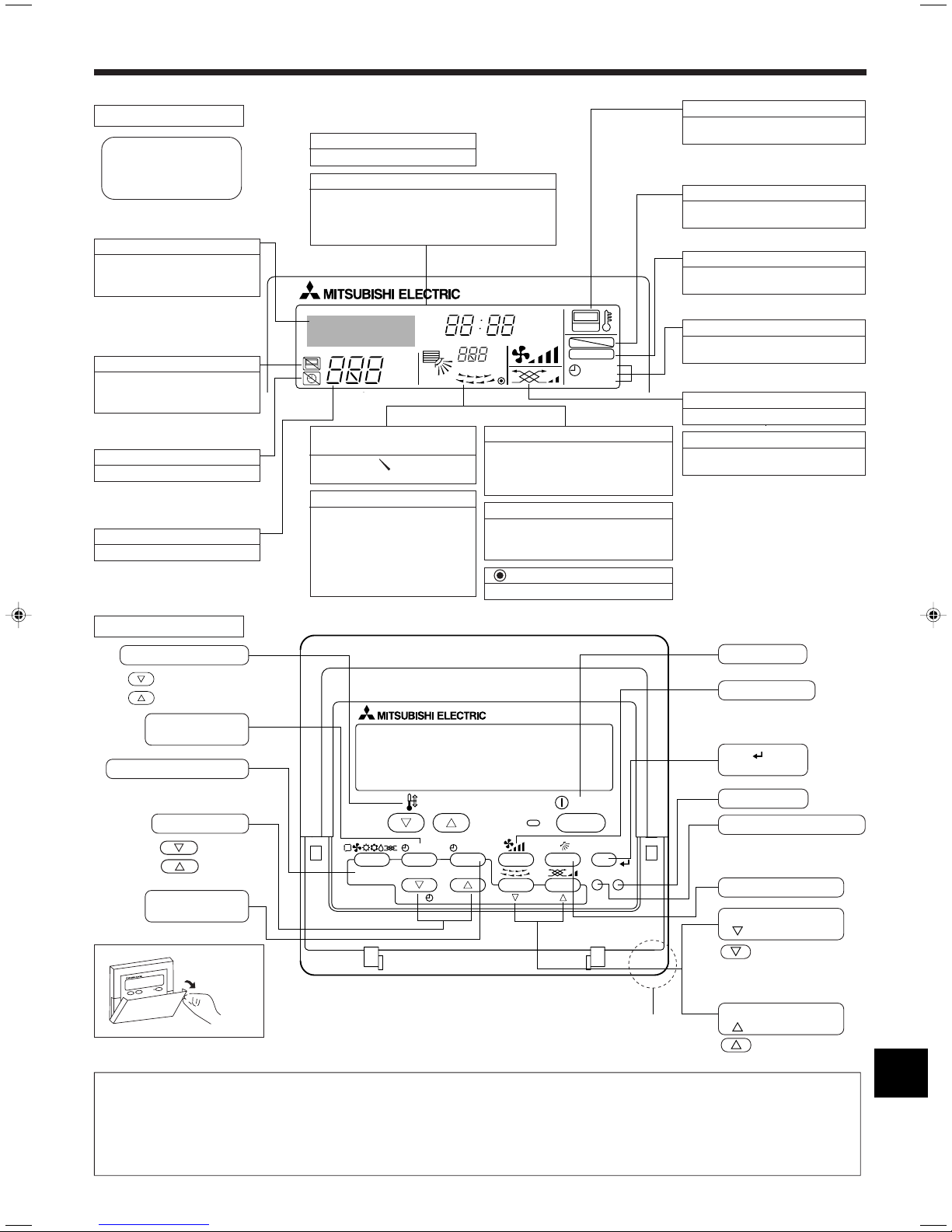
2. Parts Names
■ Wired Remote-Controller
Display Section
For purposes of this explanation,
all parts of the display are shown
as lit. During actual operation, only
the relevant items will be lit.
Identifies the current operation
Shows the operating mode, etc.
* Multilanguage display is sup-
ported.
“Centrally Controlled” indicator
Indicates that operation of the remote controller has been prohibited by a master controller.
“Timer is Off” indicator
Indicates that the timer is off.
Temperature Setting
Shows the target temperature.
Day-of-Week
Shows the current day of the week.
Time/Timer Display
Shows the current time, unless the simple or Auto Off
timer is set.
If the simple or Auto Off timer is set, shows the time
remaining.
TIME SUN MON TUE WED THU FRI SAT
TIMER
AFTER
ERROR CODE
˚F˚C
Hr
AFTER
˚F˚C
ONLY1Hr.
Up/Down Air Direction indicator
The indicator shows the direction of the outcoming airflow.
“One Hour Only” indicator
Displayed if the airflow is set to
weak and downward during COOL
or DRY mode. (Operation varies
according to model.)
The indicator goes off after one
hour, at which time the airflow direction also changes.
Room Temperature display
Shows the room temperature. The room
temperature display range is 8–39°C.
The display flashes if the temperature
is less than 8 °C or 39 °C or more.
Louver display
Indicates the action of the swing louver.
Does not appear if the louver is stationary.
(Power On indicator)
Indicates that the power is on.
ON
OFF
FUNCTION
FILTER
WEEKLY
SIMPLE
AUTO OFF
“Sensor” indication
Displayed when the remote controller
sensor is used.
“Locked” indicator
Indicates that remote controller buttons have been locked.
“Clean The Filter” indicator
Comes on when it is time to clean the
filter.
Timer indicators
The indicator comes on if the corresponding timer is set.
Fan Speed indicator
Shows the selected fan speed.
Ventilation indicator
Appears when the unit is running in
Ventilation mode.
Operation Section
Set Temperature buttons
Down
Up
Timer Menu button
(Monitor/Set button)
Mode button (Return button)
Set Time buttons
Back
Ahead
Timer On/Off button
(Set Day button)
Opening the
door.
Note:
● “PLEASE WAIT” message
This message is displayed for approximately 3 minutes when power is supplied to the indoor unit or when the unit is recovering from a power failure.
● “NOT AVAILABLE” message
Built-in temperature sensor
This message is displayed if a button is pressed to operate a function that the indoor unit does not have.
If a single remote controller is used to simultaneously operate multiple indoor units that are different models, this message will not be displayed if
any of the indoor units is equipped with the function.
ON/OFF button
Fan Speed button
Filter button
(<Enter> button)
Test Run button
Check button (Clear button)
Airflow Up/Down button
Louver button
(
Operation button)
To preceding operation
number.
Ventilation button
Operation button)
(
To next operation
number.
3
˚C
˚C
TIME SUN
PAR-21MAA
ON/OFF
FILTER
CHECK
OPERATION
CLEAR
TEST
TEMP.
MENU
BACK DAY
MONITOR/SET
CLOCK
ON/OFF
2
4
9
1
A
TIME SUN
2
3
4
˚C
˚C
PAR-21MAA
ON/OFF
FILTER
CHECK
OPERATION
CLEAR
TEST
TEMP.
MENU
BACK DAY
MONITOR/SET
CLOCK
ON/OFF
2
7
2
3
3
8
6
4
5
8
7
1
1
5
6
˚F˚C
TIMER
MON
OFF
WEEKLY
SUN MON TUE WED THU FRI SAT
WEEKLY
˚F˚C
˚C
TIME SUN
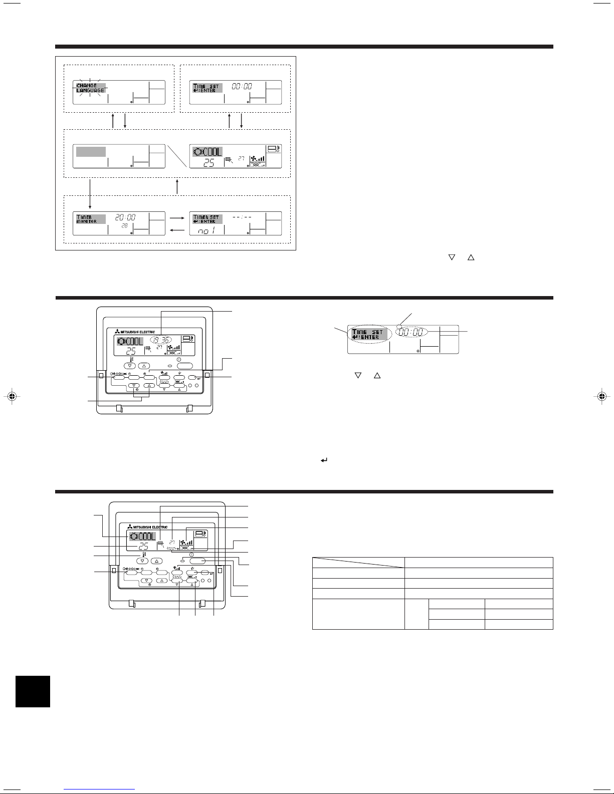
3. Screen Configuration
Function Selection of remote controller
ADC
Standard Control Screens
OFF ON
BC
Timer Monitor Timer Setup
B
Set Day/Time
4. Setting the Day of the Week and Time
Day of the Week &
Time display
<Screen Types>
For details on setting the language for the remote controller display, refer
to section 8. Function Selection.
The initial language setting is English.
● Function Selection of remote controller:
Set the functions and ranges available to the remote controller (timer functions, operating restrictions, etc.)
● Set Day/Time: Set the current day of the week or time.
● Standard Control Screens:
View and set the air conditioning system’s operating status
● Timer Monitor: View the currently set timer (weekly timer, sim-
ple timer, or Auto Off timer)
● Timer Setup: Set the operation of any of the timers (weekly
timer, simple timer, or Auto Off timer).
<How to change the screen>
A :Hold down both the Mode button and the Timer On/Off button for 2
seconds.
B :Press the Timer Menu button.
C :Press the Mode (Return) button.
D :Press either of the Set Time buttons ( or ).
Day of the Week Setting
Time Setting
Note:
The day and time will not appear if clock use has been disabled at Function
Selection of remote controller.
5. Operation
4
1. Press the or Set Time button A to show display 2.
2. Press the Timer On/Off (Set Day) button 9 to set the day.
* Each press advances the day shown at 3 : Sun → Mon → ... → Fri →
Sat.
3. Press the appropriate Set Time button A as necessary to set the time.
* As you hold the button down, the time (at 4) will increment first in
minute intervals, then in ten-minute intervals, and then in one-hour intervals.
4. After making the appropriate settings at Steps 2 and 3, press the Filter
button 4 to lock in the values.
5.1. Turning ON/OFF
<To Start Operation>
■ Press the ON/OFF button 1.
• The ON lamp 1 and the display area come on.
Note:
● When the unit is restarted, initial settings are as follows.
Remote Controller settings
Mode
Temperature setting
Fan speed
Airflow up/down
<To Stop Operation>
■ Press the ON/OFF button 1 again.
• The ON lamp 1 and the display area go dark.
Note:
Even if you press the ON/OFF button immediately after shutting down the operation is progress, the air conditioner will not start for about three minutes.
This is to prevent the internal components from being damaged.
Last operation mode
Last set temperature
Last set fan speed
COOL or DRY
Mode HEAT
FAN
Horiz. outlet
Last setting
Horiz. outlet
5. Operation
5.2. Mode select
■ Press the operation mode ( ) button 2 and select the opera-
tion mode 2.
Cooling mode
s
Drying mode
Fan mode
Heating mode
Automatic (cooling/heating) mode
Ventillation mode
Only indicated on the following condition
Wired remote controller used
LOSSNAY connected
Information for multi system air conditioner (Outdoor
unit: MXZ series)
ss
sMulti system air conditioner (Outdoor unit: MXZ series) can con-
ss
nect two or more indoor units with one outdoor unit. According to
the capacity, two or more units can operate simultaneously.
• When you try to operate two or more indoor units with one outdoor unit
simultaneously, one for the cooling and the other for heating, the operation mode of the indoor unit that operates earlier is selected. The other
indoor units that will start the operation later cannot operate, indicating
an operation state in flashing.
In this case, please set all the indoor units to the same operation mode.
• There might be a case that the indoor unit, which is operating in
(AUTO) mode. Cannot change over to the operating mode (COOL ↔
HEAT) and becomes a state of standby.
• When indoor unit starts the operation while the defrosting of outdoor
unit is being done, it takes a few minutes (max. about 15 minutes) to
blow out the warm air.
• In the heating operation, though indoor unit that does not operate may
get warm or the sound of refrigerant flowing may be heard, they are not
malfunction. The reason is that the refrigerant continuously flows into it.
Automatic operation
■ According to a set temperature, cooling operation starts if the room temperature is too hot and heating operation starts if the room temperature
is too cold.
■ During automatic operation, if the room temperature changes and remains 2 °C or more above the set temperature for 15 minutes, the air
conditioner switches to cooling mode. In the same way, if the room temperature remains 2 °C or more below the set temperature for 15 minutes, the air conditioner switches to heating mode.
Cooling mode
15 minutes (switches
from heating to cooling)
Set temperature +2°C
Set temperature
5.3. Temperature setting
ss
sTo decrease the room temperature:
ss
Press button 3 to set the desired temperature.
The selected temperature is displayed 3.
ss
sTo increase the room temperature:
ss
Press button 3 to set the desired temperature.
The selected temperature is displayed 3.
• Available temperature ranges are as follows:
Cooling/Drying: 19 - 30 °C
Heating: 17 - 28 °C
Automatic: 19 - 28 °C
• The display flashes either 8 °C - 39 °C to inform you if the room tem-
perature is lower or higher than the displayed temperature.
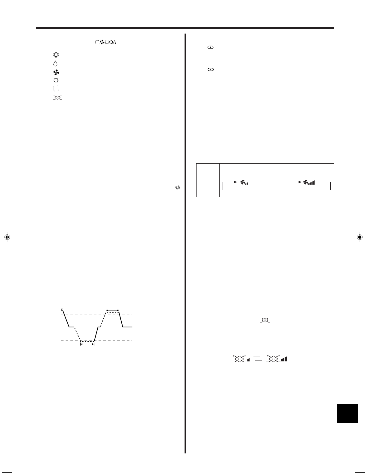
5.4. Fan speed setting
■ Press the Fan Speed button 5 as many times as necessary while the
system is running.
• Each press changes the force. The currently selected speed is shown
at 5.
• The change sequence, and the available settings, are as follows.
FAN SPEED
2-speed
model
Note:
● The number of available fan speeds depends on the type of unit connected.
Note also that some units do not provide an “Auto” setting.
● In the following cases, the actual fan speed generated by the unit will differ
from the speed shown the remote controller display.
1. While the display is showing “STAND BY” or “DEFROST”.
2. When the temperature of the heat exchanger is low in the heating mode.
(e.g. immediately after heating operation starts)
3. In HEAT mode, when room temperature is higher than the temperature
setting.
4. When the unit is in DRY mode.
Display
5.5. Ventillation
ss
sFor LOSSNAY combination
ss
5.5.1. For Wired Remote-controller
● To run the ventilator together with the indoor unit:
■ Press the ON/OFF button 1.
• The Vent indication appears on the screen (at 8). The ventilator will
now automatically operate whenever the indoor unit is running.
● To run the ventilator independently:
■ Press the Mode button 2 until appears on the display. This will
cause the ventilator to start.
15 minutes (switches
from cooling to heating )
■ Because the room temperature is automatically adjusted in order to
maintain a fixed effective temperature, cooling operation is performed a
few degrees warmer and heating operation is performed a few degrees
cooler than the set room temperature once the temperature is reached
(automatic energy-saving operation).
Set temperature -2°C
● To change the ventilator force:
■ Press the Ventilation button 8 as necessary.
• Each press toggles the setting, as shown below.
▲
▲
Low
High
5
 Loading...