

Mitsubishi Electric PEAD-A24, PEAD-A30, PEAD-A36, PEAD-A42AA, PEAD-A24AA Installation Manual
...
Air-Conditioners
PEAD-A24,30,36,42AA
FOR INSTALLER
INSTALLATION MANUAL
For safe and correct use, please read this installation manual thoroughly before installing the air-conditioner
unit.
FOR INSTALLER
English
MANUEL D’INSTALLATION
Veuillez lire le manuel d’installation en entier avant d’installer ce climatiseur pour éviter tout accident et vous
assurer d’une utilisation correcte.
POUR L’INSTALLATEUR
Français

3
YX
LW
A
Z
C Nuts (field supply)
D Washers (accessory)
E M10 hanging bolt (field supply)
B
C
D
A
F
G
3
4
E
A
C
B
A
D
C
E
1
2
50~150[2~5-15/16] 450[17-3/4]
450[17-
3
/
4
]
49[1-
15
/
16
]
625[24-
5
/
8
]
777[30-
5
/
8
]
20[13/16]
100[3-
15
/16]
23
[15/16]
250[9-
7
/
8
]
B
A
Model
PEAD-A24, 30AA
PEAD-A36, 42AA
A
1100 [43-5/16]
1400 [55-1/8]
B
1154 [45-7/16]
1454 [57-1/4]
C
1200 [47-1/4]
1500 [59-1/16]
D
1060 [41-23/32]
1360 [53-17/32]
E
1200 [47-1/4]
1500 [59-1/16]
(Unit: mm [in])
4.1
3.1
A
(Unit: mm [in])
[Fig. 3-1]
A Access door
B Electrical parts box
C Air inlet
D Air outlet
E Ceiling surface
F Service space (viewed from the side)
G Service space (viewed from the direction of arrow)
1 600 mm [23-5/8 in] or more
2 100 mm [3-15/16 in] or more
3 10 mm [7/16 in] or more
4 300 mm [11-13/16 in] or more
4
[Fig. 4-1]
A Center of gravity
5
[Fig. 5-1] [Fig. 5-2] [Fig. 5-3]
A Unit body
B Lifting machine
C
D
D
C
E
5.25.1
A Indoor unit’s bottom surface
2
6
90°
d
c
b
a
b
a
a
b
e
b
c
d
c
A
c
b
a
d e f g h
i
[Fig. 6-9]
A Pipe cover (small) (accessory)
B Caution:
Pull out the thermal insulation on the refrigerant piping at the
site, insert the flare nut to flare the end, and replace the insulation in its original position.
Take care to ensure that condensation does not form on exposed copper piping.
C Liquid end of refrigerant piping
D Gas end of refrigerant piping
E Site refrigerant piping
F Main body
G Pipe cover (large) (accessory)
H Thermal insulation (field supply)
I Pull
J Flare nut
K Return to original position
A
B
C
D
F
G
E
H
H
K
L
J
I
J
O
O
N
N
20
[25/32]
20
[25/32]
20
[25/32]
20
[25/32]
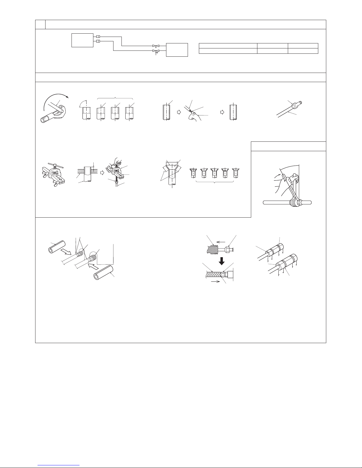
[Fig. 6-3]
[Fig. 6-6]
[Fig. 6-4] [Fig. 6-5]
a Flare nut
b Copper tube
a Burr
b Copper tube/pipe
c Spare reamer
d Pipe cutter
[Fig. 6-7]
[Fig. 6-8]
a Flaring tool
b Die
c Copper tube
d Flare nut
e Yoke
a Smooth all around
b Inside is shining without
any scratches
c Even length all around
d Too much
e Tilted
f S cra tch on
flared plane
g Cracked
h Uneven
i Bad examples
L Ensure that there is no gap here
M Plate on main body
N Band (accessory)
O Ensure that there is no gap here. Place join upwards.
6.1
6.2
a Copper tubes
b Good
c No good
d Tilted
e Uneven
f Burred
6.3
Model
PEAD-A24, 30, 36, 42AA
A
ø15.88 [5/8]Bø9.52 [3/8]
(Unit: mm [in])
[Fig. 6-1]
a
øA
øB
b
a Indoor unit
b Outdoor unit
a
dcbe f
3
F
F F
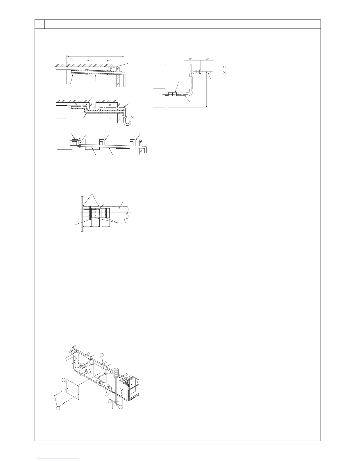
A Indoor unit
B Tie band (accessory)
C Visible part
D Insertion margin
E Drain hose (accessory)
F Drain pipe (O.D. ø32 mm [1-1/4 in] PVC TUBE, field supply)
G Insulating material (field supply)
H Tie band (accessory)
I To be gap free. The joint section of the insulation material meet must be at the top.
6
6.5
[Fig. 6-12]
A Insert pump's end 2 to 4 cm [13/16 to 1-5/8 in].
B Remove the water supply port.
C About 2500 cc
D Water
E Filling port
F Screw
A
B
F
C
D
E
B
J
O
N
F
Max. 300mm [11-13/16in]
I
B
C D D
G
F
E
H
A
32
[1-
1
/4]
35
[1-
7
/16]
25
[1]
(Unit: mm [in])
[Fig. 6-10]
Max. 20m [65ft]
1.5-2m [5-7ft]
C
A
B
K
L
B
D
E
D
I
H
M
D
G
Correct piping
Wrong piping
A Insulation (9 mm [3/8 in] or more)
B Downward slope (1/100 or more)
C Support metal
K Air bleeder
L Raised
M Odor trap
Grouped piping
D O. D. ø32 mm [1-1/4 in] PVC TUBE
E Make it as large as possible. About 10 cm [3-15/16 in].
F Indoor unit
G Make the piping size large for grouped piping.
H Downward slope (1/100 or more)
I O. D. ø38 mm [1-1/2 in] PVC TUBE for grouped piping.
(9 mm [3/8 in] or more insulation)
J Up to 550 mm [21-11/16 in]
N Drain hose (accessory)
O Horizontal or slightly upgradient
[Fig. 6-11]
4
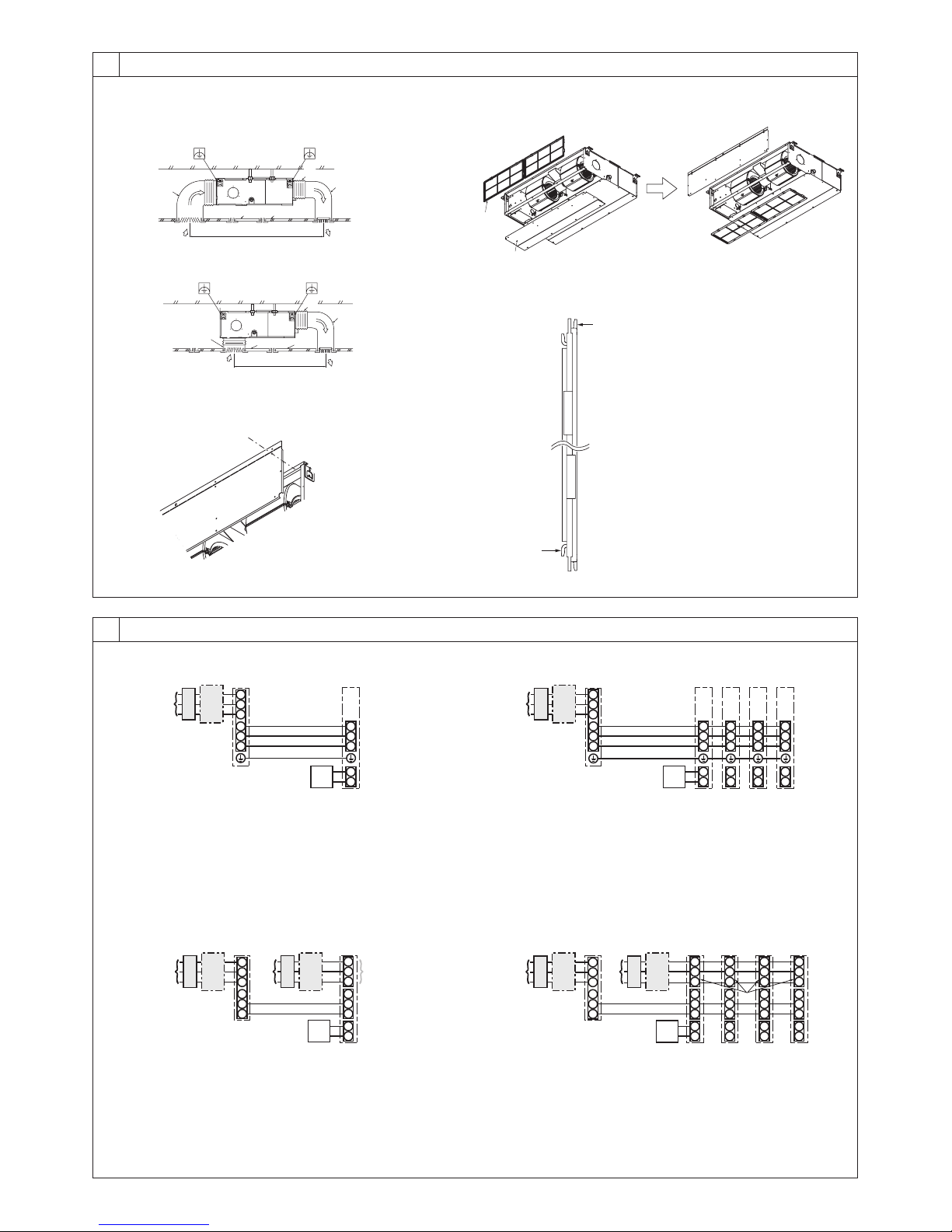
7
S1
S2
L1
L2
G
1
2
S1
S2
S3
S3
A B C
D
E
F
G
A Outdoor unit power supply
B Earth leakage breaker
C Wiring circuit breaker or isolating switch
D Outdoor unit
E Indoor unit/outdoor unit connecting cords
F Remote controller
G Indoor unit
S1
S2
1
2
S1
S2
S3
1
2
S1
S2
S3
S3
1
2
S1
S2
S3
1
2
S1
S2
S3
A B C
D
E
F
G G G G
L1
L2
G
A Outdoor unit power supply
B Earth leakage breaker
C Wiring circuit breaker or isolating switch
D Outdoor unit
E Indoor unit/outdoor unit connecting cords
F Remote controller
G Indoor unit
H Option
J Indoor unit power supply
S1
S2
1
2
S1
S2
S3
S3
A
CB
D
JEB
C
F
G
H
L1
L2
G
L1
L2
G
A Outdoor unit power supply
B Earth leakage breaker
C Wiring circuit breaker or isolating switch
D Outdoor unit
E Indoor unit/outdoor unit connecting cords
F Remote controller
G Indoor unit
H Option
J Indoor unit power supply
S1
S2
1
2
S1
S2
S3
1
2
S1
S2
S3
1
2
S1
S2
S3
1
2
S1
S2
S3
S3
A B C
D
E
J B C
F
H
G G G G
L1
L2
G
L1
L2
G
L1
L2
G
L1
L2
G
L1
L2
G
[Fig. 8-2]
[Fig. 8-3] [Fig. 8-4]
[Fig. 7-1]
[Fig. 7-2]
[Fig. 7-3]
[Fig. 7-4]
Duct
Air inlet
Access door
Canvas duct
Ceiling surface
Air outlet
Leave distanc e
enough to prevent short cycle
<A> In case of rear inlet
A
B
G
F
A
A
B
C
D
E
F
G
D
C E
<B> In case of bottom inlet
A
B
G
C
E
A
F
D
A
B
A Filter
B Bottom plate
C
D
7.1
8
[Fig. 8-1]
8.1
A Outdoor unit power supply
B Earth leakage breaker
C Wiring circuit breaker or isolating switch
D Outdoor unit
E Indoor unit/outdoor unit connecting cords
F Remote controller
G Indoor unit
5
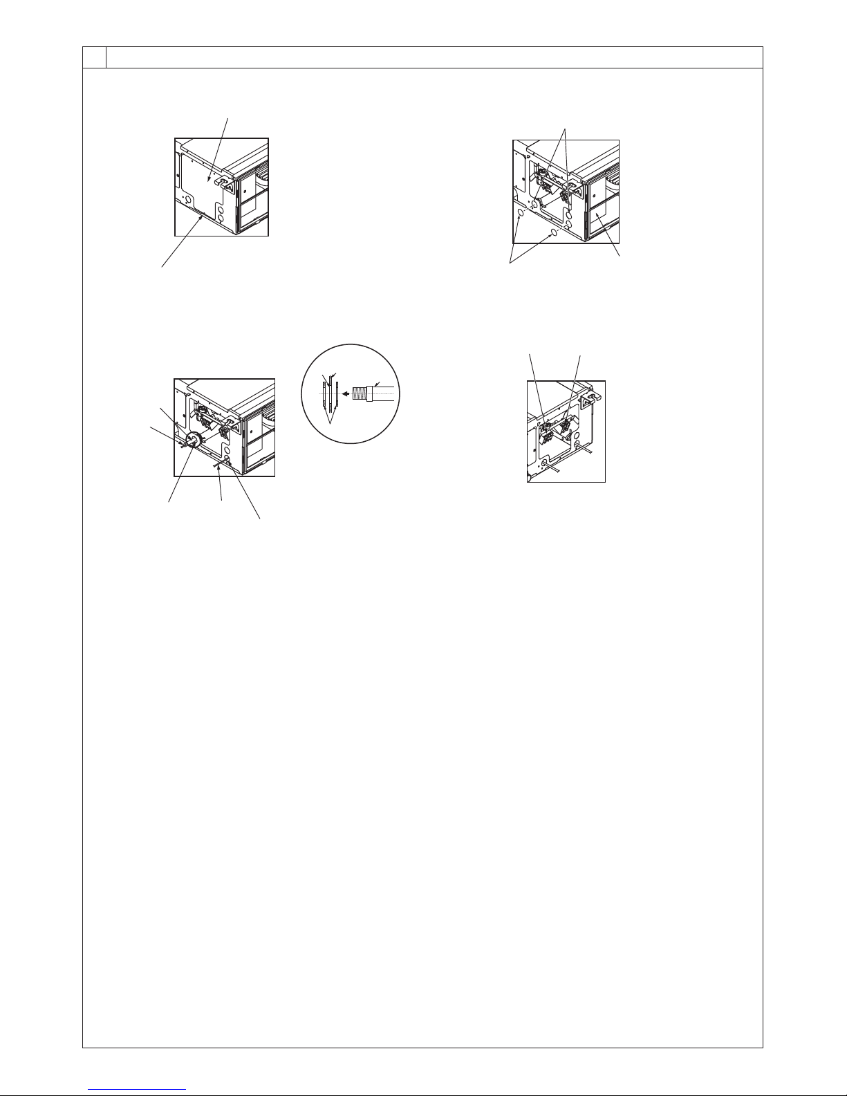
8.2
F Use PG bushing to keep the weight of the cable and external force from being applied to
the power supply terminal connector. Use a cable tie to secure the cable.
G Power source wiring
H Use ordinary bushing
I Transmission wiring
J Conduit
K Side frame
L Knockout hole (for power source wiring)
M Washer (accessory)
N Terminal block for power source and indoor transmission
O Terminal block for remote controller
[Fig. 8-2-3] [Fig. 8-2-4]
C Terminal box
D Knockout hole
E Remove
A Screw holding cover (1pc)
B Cover
[Fig. 8-2-1]
[Fig. 8-2-2]
8
A
B
D
E
C
H
I
J
G
F
O
N
L
K
J
M
6
I
I
H
B
J
H
B-1. B-2.
[Fig. 8-5]
8
A
AB TB6
B
A To the terminal block on the indoor unit
B TB6 (No polarity)
[Fig. 8-6]
8.2
46 [1-13/16]
30
[1-3/16]
120 [4-3/4]
83.5 [3-5/16]
A
B
C
30
[1-3/16]
30
[1-3/16]
A Remote controller profile
B Required clearances surrounding the remote controller
C Installation pitch
[Fig. 8-4]
[Fig. 8-3]
A Indoor terminal block
B Earth wire (green/yellow)
C Indoor/outdoor unit connecting wire 3-
core 1.5 mm
2
[AWG 16] or more
D Outdoor terminal block
1 Connecting cable
Cable 3-core 1.5 mm
2
[AWG 16], in con-
formity with Design 245 IEC 57.
2 Indoor terminal block
3 Outdoor terminal block
A Indoor terminal block
4 Always install an earth wire (1-core 1.5 mm
2
[AWG 16]) longer than other cables
5 Remote controller cable
Wire No × size (mm
2
) : Cable 2C × 0.3
This wire accessory of remote controller
(wi re len gth : 10 m [32 ft], non -pola r.
Max. 500 m [1640 ft])
6 Wired remote controller
C Indoor/outdoor unit
connecting wire
3-core 1.5 mm
2
[AWG 16] or more
D Outdoor terminal block
B Earth wire (green/yellow)
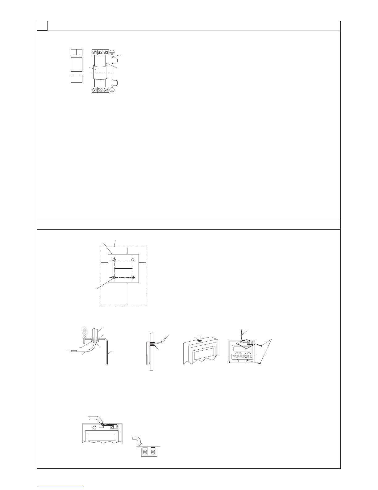
8.3
1 2
6
5
2
4
3
1
(Unit: mm [in])
A
D
C
E
F
I
G
H
A For installation in the switch box:
B For direct installation on the wall select one of the following:
• Prepare a hole through the wall to pass the remote controller cord (in order to run the remote controller cord from
the back), then seal the hole with putty.
• Run the remote controller cord through the cut-out upper case, then seal the cut-out notch with putty similarly as
above.
C Wall
D Conduit
E Lock nut
F Bushing
G Switch box
H Remote controller cord
I Seal with putty
J Wood screw
7
 Loading...