

Mitsubishi Electric PEAD-A24, PEAD-30, PEAD-42AA, PEAD-36 Installation Manual

Air-Conditioners
PEAD-A24,30,36,42AA
FOR INSTALLER
INSTALLATION MANUAL
For safe and correct use, please read this installation manual thoroughly before installing the air-conditioner
unit.
FOR INSTALLER
English
MANUEL D’INSTALLATION
Veuillez lire le manuel d’installation en entier avant d’installer ce climatiseur pour éviter tout accident et vous
assurer d’une utilisation correcte.
POUR L’INSTALLATEUR
Français
2
3
[Fig. 3-1]
4
[Fig. 4-1]
C
D
C
E
D
A Unit body
B Lifting machine
5
[Fig. 5-1] [Fig. 5-2] [Fig. 5-3]
A Center of gravity
A Indoor unit’s bottom surface
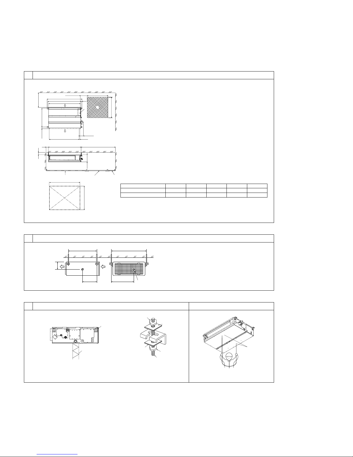
5.25.1
A Access door
B Electrical parts box
C Air inlet
D Air outlet
E Ceiling surface
F Service space (viewed from the side)
G Service space (viewed from the direction of arrow)
1 600 mm [23-5/8 in] or more
2 100 mm [3-15/16 in] or more
3 10 mm [7/16 in] or more
4 300 mm [11-13/16 in] or more
YX
LW
A
Z
C Nuts (field supply)
D Washers (accessory)
E M10 hanging bolt (field supply)
B
C
D
A
F
G
3
4
E
A
C
B
A
D
C
E
1
2
50~150[2~5-15/16] 450[17-3/4]
450[17-
3
/
4
]
49[1-
15
/
16
]
625[24-
5
/
8
]
777[30-
5
/
8
]
20[13/16]
100[3-
15
/16]
23
[15/16]
250[9-
7
/
8
]
B
A
Model
PEAD-A24, 30AA
PEAD-A36, 42AA
A
1100 [43-5/16]
1400 [55-1/8]
B
1154 [45-7/16]
1454 [57-1/4]
C
1200 [47-1/4]
1500 [59-1/16]
D
1060 [41-23/32]
1360 [53-17/32]
E
1200 [47-1/4]
1500 [59-1/16]
(Unit: mm [in])
4.1
3.1
A
(Unit: mm [in])
3
6
øB
øA
a
b
[Fig. 6-1]
a Indoor unit
b Outdoor unit
a
dcbef
90°
d
c
b
a
b
a
a
b
e
b
c
d
c
A
c
b
a
defg h
i
[Fig. 6-9]
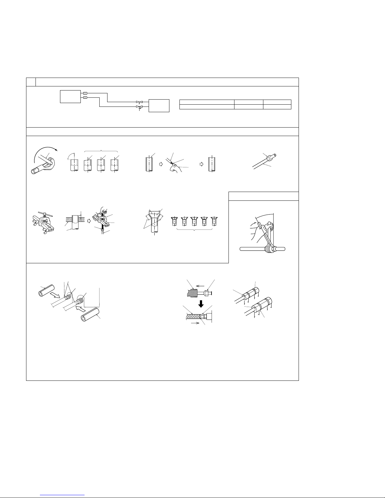
A Pipe cover (small) (accessory)
B Caution:
Pull out the thermal insulation on the refrigerant piping at the
site, insert the flare nut to flare the end, and replace the insulation in its original position.
Take care to ensure that condensation does not form on exposed copper piping.
C Liquid end of refrigerant piping
D Gas end of refrigerant piping
E Site refrigerant piping
F Main body
G Pipe cover (large) (accessory)
H Thermal insulation (field supply)
I Pull
J Flare nut
K Return to original position
A
B
C
D
F
G
E
H
H
K
L
J
I
J
O
O
N
N
20
[25/32]
20
[25/32]
20
[25/32]
20
[25/32]
[Fig. 6-3]
[Fig. 6-6]
[Fig. 6-4] [Fig. 6-5]
a Flare nut
b Copper tube
a Burr
b Copper tube/pipe
c Spare reamer
d Pipe cutter
[Fig. 6-7]
[Fig. 6-8]
a Flaring tool
b Die
c Copper tube
d Flare nut
e Yo ke
a Smooth all around
b Inside is shining without
any scratches
c Even length all around
d Too much
e Tilted
f Scratch on
flared plane
g Cracked
h Uneven
i Bad examples
L Ensure that there is no gap here
M Plate on main body
N Band (accessory)
O Ensure that there is no gap here. Place join upwards.
6.1
6.2
a Copper tubes
b Good
c No good
d Tilted
e Uneven
f Burred
6.3
Model
PEAD-A24, 30, 36, 42AA
A
ø15.88 [5/8]Bø9.52 [3/8]
(Unit: mm [in])
4
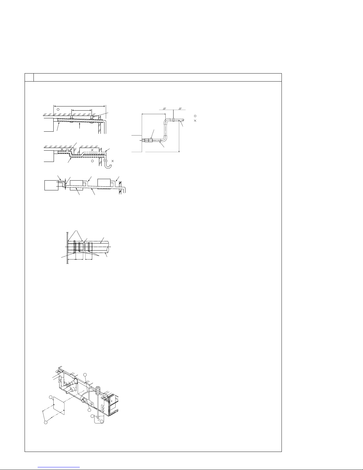
[Fig. 6-10]
Correct piping
Wrong piping
A Insulation (9 mm [3/8 in] or more)
B Downward slope (1/100 or more)
C Support metal
K Air bleeder
L Raised
M Odor trap
Grouped piping
D O. D. ø32 mm [1-1/4 in] PVC TUBE
E Make it as large as possible. About 10 cm [3-15/16 in].
F Indoor unit
G Make the piping size large for grouped piping.
H Downward slope (1/100 or more)
I O. D. ø38 mm [1-1/2 in] PVC TUBE for grouped piping.
(9 mm [3/8 in] or more insulation)
J Up to 550 mm [21-11/16 in]
N Drain hose (accessory)
O Horizontal or slightly upgradient
[Fig. 6-11]
C
B
A
L
D
D
D
E
K
M
B
H
I
Max. 20m [65ft]
1.5-2m [5-7ft]
G
F
FF
A Indoor unit
B Tie band (accessory)
C Visible part
D Insertion margin
E Drain hose (accessory)
F Drain pipe (O.D. ø32 mm [1-1/4 in] PVC TUBE, field supply)
G Insulating material (field supply)
H Tie band (accessory)
I To be gap free. The joint section of the insulation material meet must be at the top.
6
6.5
[Fig. 6-12]
A Insert pump's end 2 to 4 cm [13/16 to 1-5/8 in].
B Remove the water supply port.
C About 2500 cc
D Water
E Filling port
F Screw
A
B
F
C
D
E
B
J
O
N
F
Max. 300mm [11-13/16in]
I
B
CD D
G
F
E
H
A
32
[1-
1
/4]
35
[1-
7
/16]
25
[1]
(Unit: mm [in])
5
8
[Fig. 8-1]
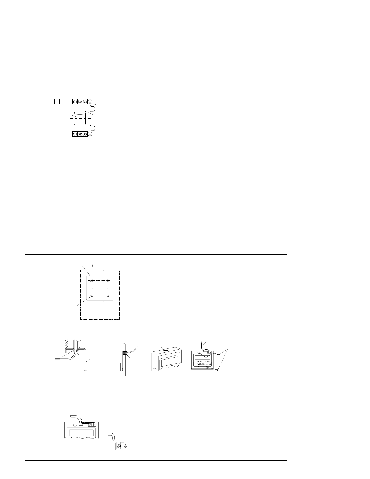
8.1
7
7.1
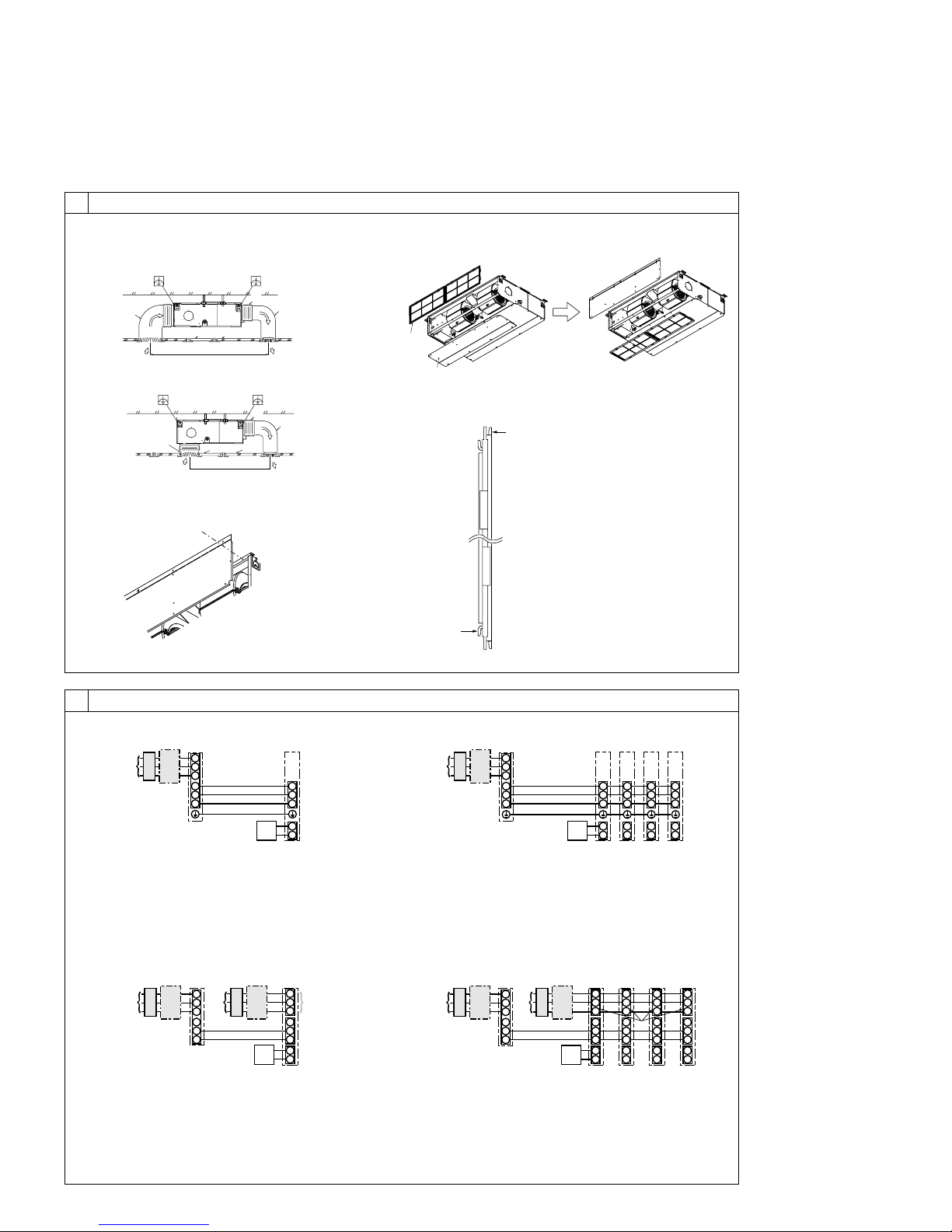
A Outdoor unit power supply
B Earth leakage breaker
C Wiring circuit breaker or isolating switch
D Outdoor unit
E Indoor unit/outdoor unit connecting cords
F Remote controller
G Indoor unit
S1
S2
L1
L2
G
1
2
S1
S2
S3
S3
AB C
D
E
F
G
A Outdoor unit power supply
B Earth leakage breaker
C Wiring circuit breaker or isolating switch
D Outdoor unit
E Indoor unit/outdoor unit connecting cords
F Remote controller
G Indoor unit
S1
S2
1
2
S1
S2
S3
1
2
S1
S2
S3
S3
1
2
S1
S2
S3
1
2
S1
S2
S3
ABC
D
E
F
GGGG
L1
L2
G
A Outdoor unit power supply
B Earth leakage breaker
C Wiring circuit breaker or isolating switch
D Outdoor unit
E Indoor unit/outdoor unit connecting cords
F Remote controller
G Indoor unit
H Option
J Indoor unit power supply
S1
S2
1
2
S1
S2
S3
S3
A
CB
D
JEB
C
F
G
H
L1
L2
G
L1
L2
G
A Outdoor unit power supply
B Earth leakage breaker
C Wiring circuit breaker or isolating switch
D Outdoor unit
E Indoor unit/outdoor unit connecting cords
F Remote controller
G Indoor unit
H Option
J Indoor unit power supply
S1
S2
1
2
S1
S2
S3
1
2
S1
S2
S3
1
2
S1
S2
S3
1
2
S1
S2
S3
S3
ABC
D
E
JBC
F
H
GGGG
L1
L2
G
L1
L2
G
L1
L2
G
L1
L2
G
L1
L2
G
[Fig. 8-2]
[Fig. 8-3] [Fig. 8-4]
[Fig. 7-1]
[Fig. 7-2]
[Fig. 7-3]
[Fig. 7-4]
Duct
Air inlet
Access door
Canvas duct
Ceiling surface
Air outlet
Leave distance
enough to prevent short cycle
<A> In case of rear inlet
A
B
G
F
A
A
B
C
D
E
F
G
D
CE
<B> In case of bottom inlet
A
B
G
C
E
A
F
D
A
B
A Filter
B Bottom plate
C
D
6
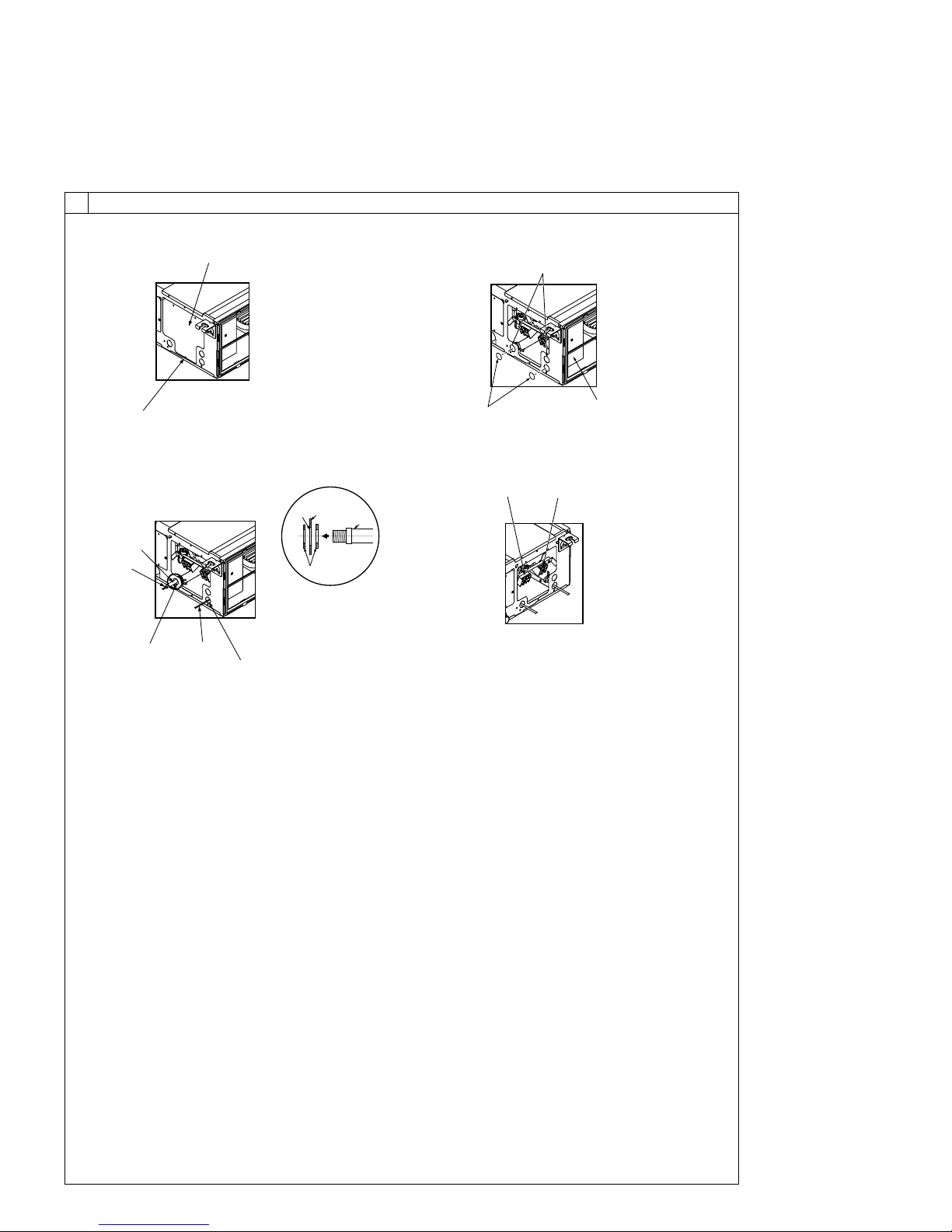
8.2
F Use PG bushing to keep the weight of the cable and external force from being applied to
the power supply terminal connector. Use a cable tie to secure the cable.
G Power source wiring
H Use ordinary bushing
I Transmission wiring
J Conduit
K Side frame
L Knockout hole (for power source wiring)
M Washer (accessory)
N Ter minal block for power source and indoor transmission
O Ter minal block for remote controller
[Fig. 8-2-3] [Fig. 8-2-4]
C Ter minal box
D Knockout hole
E Remove
A Screw holding cover (1pc)
B Cover
[Fig. 8-2-1]
[Fig. 8-2-2]
8
A
B
D
E
C
H
I
J
G
F
O
N
L
K
J
M
7
A For installation in the switch box:
B For direct installation on the wall select one of the following:
• Prepare a hole through the wall to pass the remote controller cord (in order to run the remote controller cord from
the back), then seal the hole with putty.
• Run the remote controller cord through the cut-out upper case, then seal the cut-out notch with putty similarly as
above.
C Wall
D Conduit
E Lock nut
F Bushing
G Switch box
H Remote controller cord
I Seal with putty
J Wood screw
F
A
H
C
D
E
G
I
I
I
H
B
J
H
B-1. B-2.
[Fig. 8-5]
8
A
AB TB6
B
A To the ter minal block on the indoor unit
B TB6 (No polarity)
[Fig. 8-6]
8.2
46 [1-13/16]
30
[1-3/16]
120 [4-3/4]
83.5 [3-5/16]
A
B
C
30
[1-3/16]
30
[1-3/16]
A Remote controller profile
B Required clearances surrounding the remote controller
C Installation pitch
[Fig. 8-4]
[Fig. 8-3]
A Indoor terminal block
B Earth wire (green/yellow)
C Indoor/outdoor unit connecting wire 3-
core 1.5 mm
2
[AWG 16] or more
D Outdoor terminal block
1 Connecting cable
Cable 3-core 1.5 mm
2
[AWG 16], in con-
formity with Design 245 IEC 57.
2 Indoor terminal block
3 Outdoor terminal block
A Indoor terminal block
4 Always install an earth wire (1-core 1.5 mm
2
[AWG 16]) longer than other cables
5 Remote controller cable
Wire No × size (mm
2
) : Cable 2C × 0.3
This wire accessory of remote controller
(wire length : 10 m [32 ft], non-polar.
Max. 500 m [1640 ft])
6 Wired remote controller
C Indoor/outdoor unit
connecting wire
3-core 1.5 mm
2
[AWG 16] or more
D Outdoor terminal block
B Earth wire (green/yellow)
8.3
12
6
5
2
4
3
1
(Unit: mm [in])
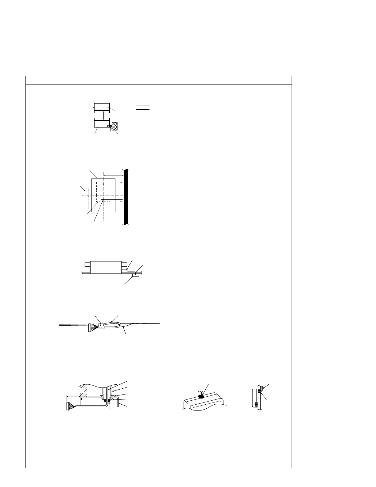
8
A
B
C
D
E
G
H
F
A Signal receiving unit external
B Center of Switch box
C Switch box
D Installation pitch
E 6.5 mm (1/4 inch)
F 70 mm (2 - 3/4 inch)
G 83.5 ± 0.4 mm (3 - 9/32 inch)
H Protrusion (pillar, etc)
[Fig. 8-9]
A
B
C
A Remote controller wire
B Hole (drill a hole on the ceiling to pass the remote controller wire.)
C Signal Receiving Unit
Ceiling cassette type, Ceiling concealed type
[Fig. 8-10]
A
B
C
A Fix tightly with tape.
B Remote controller wire
C Order wire
Indoor unit
[Fig. 8-8]
[Fig. 8-11]
H
J
I
When using the switch box
When installing directly on the wall
A 150 mm (5 - 15/16 inch)
B Remote controller wire (Accessory)
C Wiring pipe
D Locknut
H Seal around here with putty
I Remote controller wire
J Seal around here with putty
E Bushing
F Switch box
G Seal around here with putty
C
D
B
F
E
G
A
Wall
8
8.4
IC
OC(00)
CN90
TB1
TB4
1
D
C
A
B
Standard 1:1
[Fig. 8-7]
A Outdoor unit
B Refrigerant address
C Indoor unit
D Signal receiving unit
Indoor/outdoor wiring
Signal receiving unit wiring
9
8
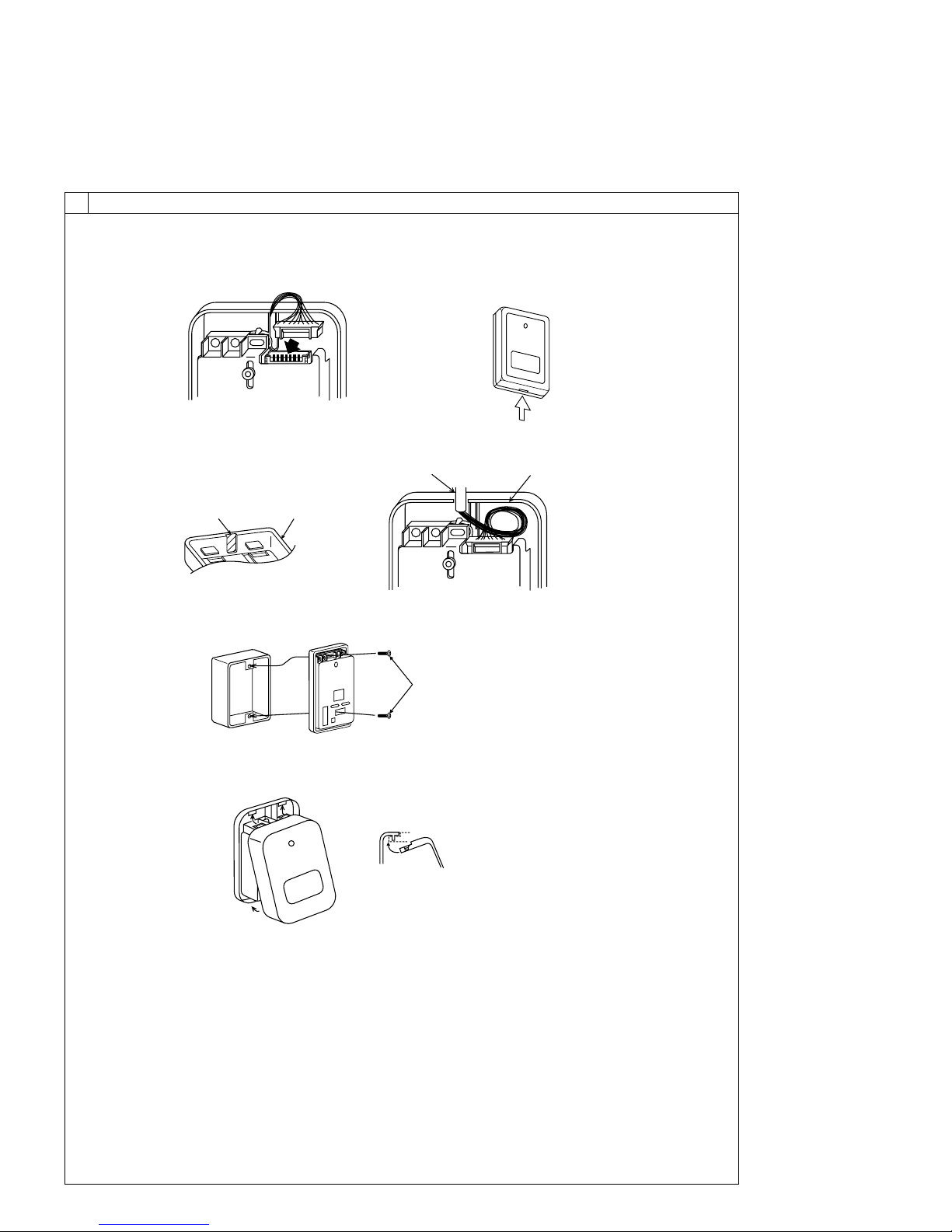
8.4
[Fig. 8-12]
[Fig. 8-13]
AB
C
D
A Thin-wall portion
B Bottom case
C Remote controller wire
D Conducting wire
[Fig. 8-14]
A
A Screw (M4 x 30)
* When installing the lower case directly on the wall or the ceiling,
use wood screws.
Insert the minus screwdriver toward the
arrow pointed and wrench it to remove the
cover.
A flat screwdriver whose width of blade is
between 4 and 7mm (5/32 - 9/32inch)
must be used.
[Fig. 8-15]
1
1
2
A
1 Hang the cover to the upper hooks (2 places).
2 Mount the cover to the lower case
A Cross-section of upper hooks
10
8
8.4
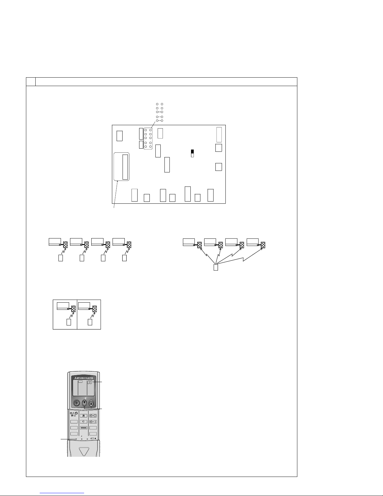
[Fig. 8-16]
IC IC IC IC
CN90 CN90 CN90 CN90
Pair number: 0
[Fig. 8-17]
IC
CN90
IC
CN90
Pair number: 0 Pair number: 0
Pair number: 0 Pair number: 0
IC IC IC IC
CN90 CN90 CN90 CN90
[Fig. 8-19]
[Fig. 8-18]
Pair number: 0 Pair number: 1 Pair number: 2 Pair number: 3
Pair number: 0 Pair number: 1 Pair number: 2 Pair number: 3
Pair number: 0 Pair number: 0 Pair number: 0 Pair number: 0
A
CN2A
CN3C
SW2
SW1
JP1
JP2
JP3
JP41
JP42
CN22
CN2L
CNXA2
CN32
SWE
CN20
CN90
CN105
CN41
CN4F
CN51
CNXB2
CNXC2
CN44
ON
OFF
<Indoor controller board>
ON/OFF TEMP
FAN
VANE
TEST RUN
AUTO STOP
AUTO START
h
min
LOUVER
MODE
CHECK
RESETSET CLOCK
CHECK
2,4
3
A
[Fig. 8-20]
11
9
[Fig. 9-1] [Fig. 9-2]
9.2
A ON/OFF button
B Test run display
C Indoor temperature liquid line
temperature display
D ON/OFF lamp
E Power display
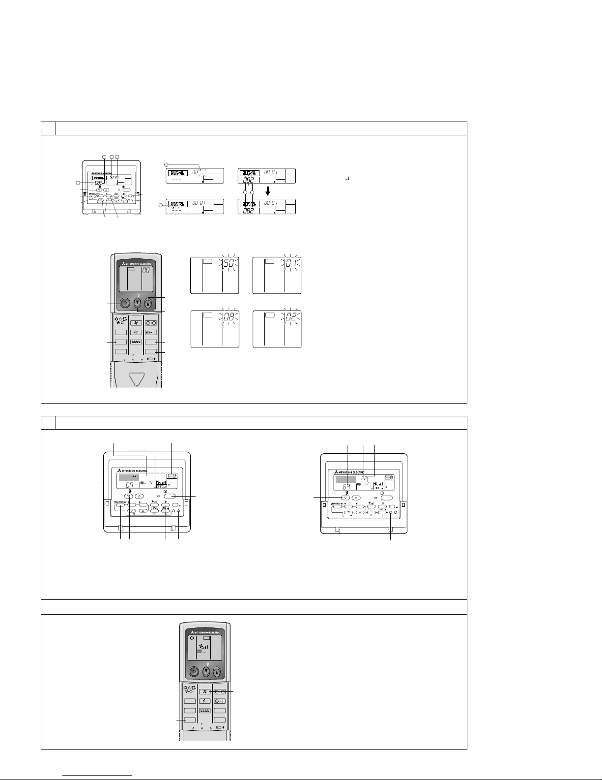
A CHECK button
B Refrigerant address
C TEMP. button
D IC: Indoor unit
OC: Outdoor unit
E Check code
F Error code display
Test run remaining time display
G Set temperature button
H Mode selection button
I Fan speed button
M TEST button
8
8.5
[Fig. 8-21]
PAR-21MAA
ON/OFF
FILTER
CHECK
OPERATION
CLEAR
TEST
TEMP.
MENU
BACK DAY
MONITOR/SET
CLOCK
ON/OFF
A
B
DC
G
E
F
4
1
213 4
1 2
A Filter button (<Enter> button)
B TEST button
C Set Time button
D Timer On/Off button (Set Day button)
E Mode selection button
F Set temperature button
G Timer Menu button (Monitor/Set button)
⁄ Mode number
⁄ Setting number
⁄ Refrigerant address
⁄ Unit number
1
2
3
4
3
12
CHECK CHECK
CHECKCHECK
4
ON/OFF TEMP
FAN
VANE
TEST RUN
AUTO STOP
AUTO START
h
min
LOUVER
MODE
CHECK
RESETSET CLOCK
CHECK
E
F
D
C
A
B
A Hour button
B Minute button
C TEMP button
D TEMP button
E ON/OFF button
F CHECK button
[Fig.8-22]
[Fig. 9-3]
A TEST RUN button
B MODE button
C FAN button
D VANE button
9.3
ON/OFF TEMP
FAN
VANE
TEST RUN
AUTO STOP
AUTO START
h
min
LOUVER
MODE
CHECK
RESETSET CLOCK
TEST RUN
B
A
C
D
˚F
˚F
SIMPLE
PAR-21MAA
ON/OFF
FILTER
CHECK
OPERATION
CLEAR
TEST
TEMP.
MENU
BACK DAY
MONITOR/SET
CLOCK
ON/OFF
TEST RUN
COOL, HEAT
A
FCEDB
MIH G
˚C
˚F
SIMPLE
PAR-21MAA
ON/OFF
FILTER
CHECK
OPERATION
CLEAR
TEST
TEMP.
MENU
BACK DAY
MONITOR/SET
CLOCK
ON/OFF
B
C
A
E D
 Loading...