

Mitsubishi PLA-A24EA7, PKA-A18HA7, PKA-A12HA7, PKA-A24KA7, PKA-A36KA7 Service Manual
...
P-SERIES
Contents
1 REFERENCE SERVICE MANUAL...................................................................................................................................4
1-1. INDOOR UNIT ..........................................................................................................................................................4
2-1. OUTDOOR UNIT ......................................................................................................................................................4
2 SPECIFICATIONS ............................................................................................................................................................5
2-1. INVERTER CEILING CASSETTE TYPE(PLA) ......................................................................................................... 5
2-2. INVERTER WALL-MOUNTED TYPE (PKA) .............................................................................................................7
2-3. INVERTER CEILING-SUSPENDED TYPE (PCA) .................................................................................................... 9
2-4. INVERTER CEILING CONCEALED TYPE (PEAD) ................................................................................................ 11
2-5. INVERTER MULTI POSITION TYPE (PVA) ............................................................................................................ 13
2-6. HYPER HEATING INVERTER ................................................................................................................................ 15
3 OUTLINES AND DIMENSIONS ..................................................................................................................................... 20
INDOOR UNIT ................................................................................................................................................................ 20
PLA-A12EA7 PLA-A18EA7 PLA-A24EA7 PLA-A30EA7 PLA-A36EA7 PLA-A42EA7 ............................... 20
PKA-A12HA7 PKA-A18HA7 .............................................................................................................................. 21
PKA-A24KA7 PKA-A30KA7 PKA-A36KA7 .................................................................................................... 22
PCA-A24KA7 PCA-A30KA7 .............................................................................................................................. 23
PCA-A36KA7 PCA-A42KA7 .............................................................................................................................. 24
PEAD-A12AA7 PEAD-A18AA7 PEAD-A24AA7 ............................................................................................. 25
PEAD-A30AA7 PEAD-A36AA7 PEAD-A42AA7 ............................................................................................. 25
PVA-A12AA7 PVA-A18AA7 PVA-A24AA7 .....................................................................................................27
PVA-A30AA7 PVA-A36AA7 PVA-A42AA7 .....................................................................................................27
PVA-A12AA7 PVA-A18AA7 PVA-A24AA7 .....................................................................................................28
PVA-A30AA7 PVA-A36AA7 PVA-A42AA7 .....................................................................................................28
OUTDOOR UNIT ............................................................................................................................................................ 29
PUZ-A12/18NKA7 PUZ-A12/18NKA7-BS PUY-A12/18NKA7 PUY-A12/18NKA7-BS ................................. 29
PUZ-A24/30NHA7 PUZ-A24/30NHA7-BS ........................................................................................................ 30
PUY-A24/30NHA7 PUY-A24/30NHA7-BS ......................................................................................................... 30
PUZ-A36/42NKA7 PUZ-A36/42NKA7-BS ......................................................................................................... 31
PUY-A36/42NKA7 PUY-A36/42NKA7-BS ......................................................................................................... 31
PUZ-HA30NHA5 PUZ-HA36NHA5 ................................................................................................................... 32
PUZ-HA42NKA .....................................................................................................................................................33
WIRED REMOTE CONTROLLER ....................................................................................................................... 34
WIRELESS REMOTE CONTROLLER ................................................................................................................. 35
4 POSITION OF THE CENTER OF GRAVITY ........................................................................................................36
4-1. INDOOR UNIT ..............................................................................................................................................36
4-2. OUTDOOR UNIT ..........................................................................................................................................37
5 WIRING DIAGRAM ........................................................................................................................................................ 38
5-1. INDOOR UNIT ........................................................................................................................................................38
PLA-A12EA7 PLA-A18EA7 PLA-A24EA7 PLA-A30EA7 PLA-A36EA7 PLA-A42EA7 ............................... 38
PKA-A12HA7 PKA-A18HA7 ............................................................................................................................... 39
PKA-A24KA7 PKA-A30KA7 PKA-A36KA7 .................................................................................................... 40
PCA-A24KA7 PCA-A30KA7 PCA-A36KA7 PCA-A42KA7 .......................................................................... 41
PEAD-A12AA7 PEAD-A18AA7 PEAD-A24AA7 PEAD-A30AA7 PEAD-A36AA7 PEAD-A42AA7 .................. 42
PVA-A12AA7 PVA-A18AA7 PVA-A24AA7 PVA-A30AA7 PVA-A36AA7 PVA-A42AA7 ...................................43
5-2. OUTDOOR UNIT ....................................................................................................................................................44
PUZ-A12/18NKA7 PUZ-A12/18NKA7-BS PUY-A12/18NKA7 PUY-A12/18NKA7-BS ................................. 44
PUZ-A24/30NHA7 PUZ-A24/30NHA7-BS PUY-A24/30NHA7 PUY-A24/30NHA7-BS ................................ 45
PUZ-A36/42NKA7 PUZ-A36/42NKA7-BS PUY-A36/42NKA7 PUY-A36/42NKA7-BS ................................. 46
PUZ-HA30NHA5 PUZ-HA36NHA5 ................................................................................................................. 47
PUZ-HA42NKA .....................................................................................................................................................48
© 2017 Mitsubishi Electric US, Inc.
P-Series (March 2017)
1

P-SERIES
6 REFRIGERANT SYSTEM DIAGRAM ............................................................................................................................ 49
6-1. INDOOR UNIT ........................................................................................................................................................49
PLA-A·EA7 ........................................................................................................................................................... 49
PKA-A·HA7 ..........................................................................................................................................................49
PCA-A·KA7 ..........................................................................................................................................................50
PEAD-A·AA7 ........................................................................................................................................................ 50
PVA-A·AA7 ...........................................................................................................................................................50
6-2. OUTDOOR UNIT ....................................................................................................................................................51
PUZ-A12NKA7 PUZ-A18NKA7 .......................................................................................................................... 51
PUZ-A12NKA7-BS PUZ-A18NKA7-BS .............................................................................................................. 51
PUZ-A24NHA7 PUZ-A30NHA7 PUZ-A36NKA7 PUZ-A42NKA7 ................................................................... 51
PUZ-A24NHA7-BS PUZ-A30NHA7-BS PUZ-A36NKA7-BS PUZ-A42NKA7-BS ........................................... 51
PUY-A12NKA7 PUY-A18NKA7 .......................................................................................................................... 52
PUY-A12NKA7-BS PUY-A18NKA7-BS .............................................................................................................. 52
PUY-A24NHA7 PUY-A30NHA7 PUY-A36NKA7 PUY-A42NKA7.................................................................... 52
PUY-A24NHA7-BS PUY-A30NHA7-BS PUY-A36NKA7-BS PUY-A42NKA7-BS............................................ 52
PUZ-HA30NHA5 PUZ-HA36NHA5 .................................................................................................................... 53
PUZ-HA42NKA .....................................................................................................................................................54
7 PERFORMANCE CURVES ...........................................................................................................................................55
FOR THE COMBINATION OF OUTDOOR UNIT PUZ-A·NKA7(-BS) PUZ-A·NHA7(-BS) ...............................................55
Cooling performance curve .................................................................................................................................. 55
FOR THE COMBINATION OF OUTDOOR UNIT PUY-A·NKA7(-BS) PUY-A·NHA7(-BS) ................................................56
Cooling performance curve .................................................................................................................................. 56
Heating performance curve .................................................................................................................................. 57
FOR THE COMBINATION OF OUTDOOR UNIT PUZ-HA·NHA5 PUZ-HA·NKA .........................................................58
Cooling performance curve .................................................................................................................................. 58
Rated heating performance curve .................................................................................................................................. 59
Rated heating capacity ................................................................................................................................................... 59
8 PERFORMANCE CHART ..............................................................................................................................................60
8-1. INVERTER .............................................................................................................................................................. 60
8-1-1. COOLING CAPACITY................................................................................................................................60
8-1-2. HEATING CAPACITY ................................................................................................................................74
8-2. HYPER HEATING INVERTER ................................................................................................................................ 76
8-2-1. COOLING CAPACITY................................................................................................................................76
8-2-2. HEATING CAPACITY ................................................................................................................................82
9 CORRECTION FACTORS .............................................................................................................................................84
9-1. INVERTER .............................................................................................................................................................. 84
9-2. HYPER HEATING INVERTER ................................................................................................................................ 86
10 AIR FLOW DATA ............................................................................................................................................................ 87
10-1. OUTLET AIR SPEED AND COVERAGE RANGE ...............................................................................................87
10-2. PLA-A·EA7 ............................................................................................................................................................ 88
10-2-1. FRESH AIR INTAKE AND BRANCH DUCT.............................................................................................88
10-3. PKA-A-HA7 ......................................................................................................................................................... 103
10-3-1. TEMPERATURE AND AIR FLOW DISTRIBUTIONS............................................................................. 103
10-4. PKA-A-KA7 .........................................................................................................................................................107
10-4-1. TEMPERATURE AND AIR FLOW DISTRIBUTIONS............................................................................. 107
10-5. PCA-A-KA7 ......................................................................................................................................................... 113
10-5-1. TEMPERATURE AND AIR FLOW DISTRIBUTIONS............................................................................. 113
10-6. PEAD-A·AA7 ....................................................................................................................................................... 122
10-6-1. INDOOR FAN PERFORMANCE AND CORRECTED AIR FLOW .........................................................122
10-7. PVA-A·AA7 ..........................................................................................................................................................129
10-7-1. INDOOR FAN PERFORMANCE AND CORRECTED AIR FLOW .........................................................129
Due to continuing improvement, above specication may be subject to change without notice.
P-Series (March 2017)
2
© 2017 Mitsubishi Electric US, Inc.

P-SERIES
10 AIR FLOW DATA .......................................................................................................................................................... 130
11 NOISE CRITERION CURVES .....................................................................................................................................136
11-1. INDOOR UNIT .....................................................................................................................................................136
11-2. OUTDOOR UNIT ................................................................................................................................................. 149
12 OPTIONAL PARTS .......................................................................................................................................................152
OPTIONAL PARTS LIST FOR INDOOR [P-SERIES] ..................................................................................................152
OPTIONAL PARTS LIST FOR OUTDOOR [P-SERIES] ..............................................................................................154
13 SYSTEM CONTROL .................................................................................................................................................... 156
Due to continuing improvement, above specication may be subject to change without notice.
P-Series (March 2017)
© 2017 Mitsubishi Electric US, Inc.
3
1 REFERENCE SERVICE MANUAL
For information on service, please refer to the service manual as follows.
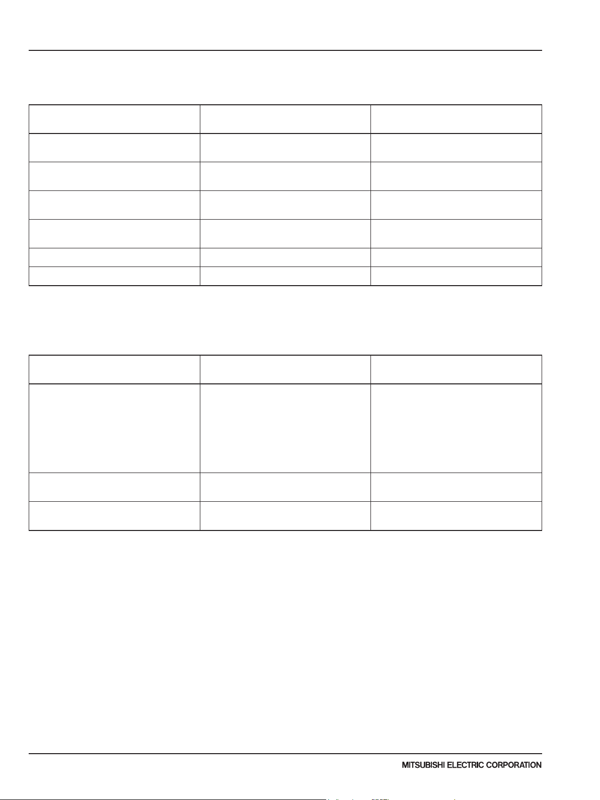
1-1. INDOOR UNIT
Model name Service Ref.
PLA-A12/18/24/30/36/42EA7 PLA-A12/18/24/30/36/42EA7
PKA-A12/18HA7 PKA-A12/18HA7
PKA-A24/30/36KA7 PKA-A24/30/36KA7.TH
PCA-A24/30/36/42KA7 PCA-A24/30/36/42KA7.TH
Service
Manual No.
OCH640
OBH640
OCH637
OBH637
OCH639
OBH639
OCH638
OBH638
PEAD-A12/18/24/30/36/42AA7 PEAD-A12/18/24/30/36/42AA7 HWE16080
PVA-A12/18/24/30/36/42AA7 PVA-A12/18/24/30/36/42AA7 MD-1404-K011
1-2. OUTDOOR UNIT
Model name Service Ref.
PUZ-A12/18/36/42NKA7
PUZ-A24/30NHA7
PUZ-A12/18/36/42NKA7-BS
PUZ-A24/30NHA7-BS
PUY-A12/18/36/42NKA7
PUY-A24/30NHA7-BS
PUY-A12/18/36/42NKA7-BS
PUY-A24/30NHA7-BS
PUZ-A12/18/36/42NKA7
PUZ-A24/30NHA7
PUZ-A12/18/36/42NKA7-BS
PUZ-A24/30NHA7-BS
PUY-A12/18/36/42NKA7
PUY-A24/30NHA7-BS
PUY-A12/18/36/42NKA7-BS
PUY-A24/30NHA7-BS
Service
Manual No.
OCH636
OCB636
PUZ-HA30/36NHA5 PUZ-HA30/36NHA5
PUZ-HA42NKA PUZ-HA42NKA
Due to continuing improvement, above specication may be subject to change without notice.
P-Series (March 2017)
4
OCH607
OCB607
OCH567
OCB567
© 2017 Mitsubishi Electric US, Inc.
2 SPECIFICATIONS
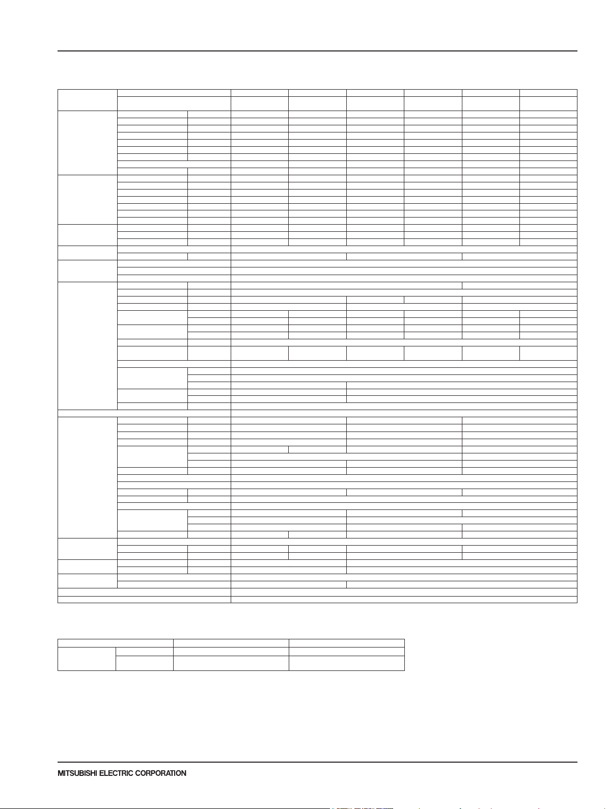
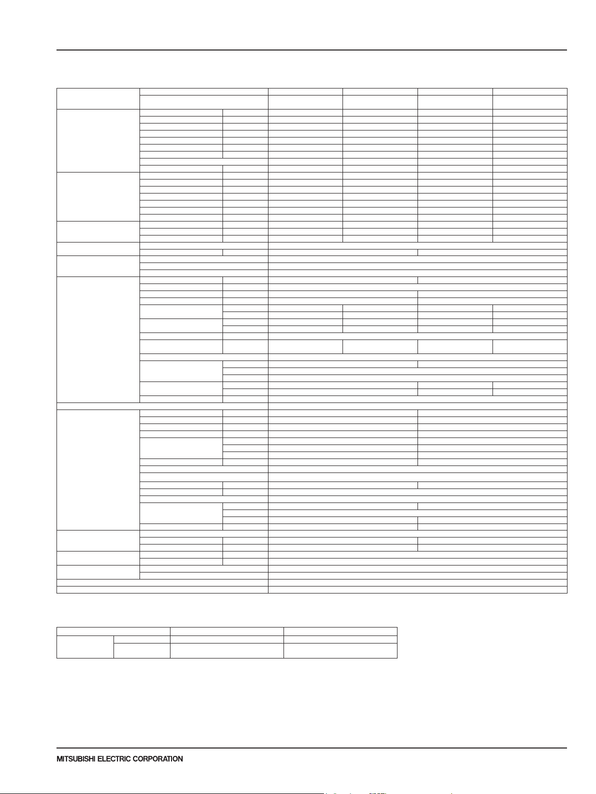
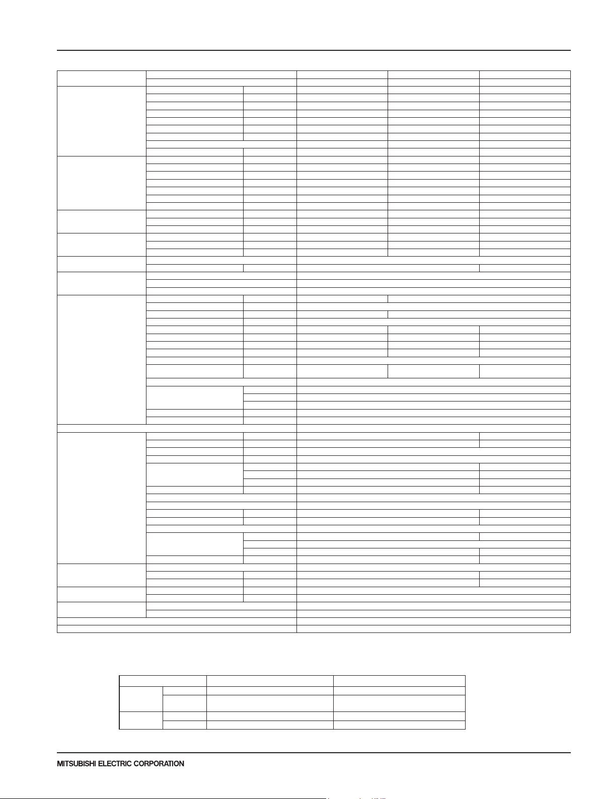
2-1. INVERTER CEILING CASSETTE TYPE (PLA)
Model name Indoor unit PLA-A12EA7 PLA-A18EA7 PLA-A24EA7 PLA-A30EA7 PLA-A36EA7 PLA-A42EA7
Cooling Max. Capacity Btu/h 12,000 18,000 24,000 30,000 36,000 42,000
Heating Max. Capacity Btu/h - - - - - -
Heating
at low ambient
Power supply Phase,Cycle,Voltage 1phase, 60Hz, 208/230V
Voltage Indoor - Outdoor S1-S2 AC208V / 230V
Indoor unit MCA A 1 2
Remote controller Attached in indoor unit
Outdoor unit MCA A 11 19 25
Refrigerant Type R410A
Refrigerant pipe size Gas side O.D. mm[inch] 12.7[1/2] 15.88[5/8]
Refrigerant pipe length
Refrigerant piping Not Supplied
Connection Method Flared
NOTES : *1.Rating conditions (cooling)-Indoor : D.B. 26.7°C(80°F), W.B. 19.4°C(67°F) Outdoor : D.B. 35°C(95°F), W.B. 23.9°C(75°F)
Outdoor unit PUY-A12NKA7 PUY-A18NKA7 PUY-A24NHA7 PUY-A30NHA7 PUY-A36NKA7 PUY-A42NKA7
Rated Capacity Btu/h 12,000 18,000 24,000 30,000 36,000 42,000
Min. Capacity Btu/h 5,800 8,000 10,000 9,000 16,000 16,000
Total Input W 730 1,250 1,670 2,540 2,780 3,590
EER Btu/h/W 16.4 14.4 14.3 11.8 12.9 11.6
SEER Btu/h/W 27.0 24.6 24.2 22.8 21.8 21.0
Moisture Removal Pints/h 1.2 2.4 3.0 5.4 4.5 7.9
SHF 0.89 0.85 0.86 0.80 0.86 0.79
Power factor % 93.4 95.3 94.3 95.2 93.7 94.6
Rated Capacity Btu/h - - - - - Min. Capacity Btu/h - - - - - Total Input W - - - - - COP W/W - - - - - HSPF(IV/V) Btu/h/W - - - - - Power factor % - - - - - Rated Capacity Btu/h - - - - - Total Input W - - - - - COP W/W - - - - - -
Breaker size A 15 25 30
Indoor - Outdoor S2-S3 DC24V
Indoor - Remote controller
MOCP A 15
Fan Motor F.L.A 0.36 0.60 0.74 0.95
Fan Motor Output W 50 120 120
Air ow DRY
(Lo-M2-M1-Hi) WET
Air ow DRY
(Lo-M2-M1-Hi) WET
External pressure in.WG[Pa] 0
Sound level
(Lo-M2-M1-Hi)
External nish White Munsell 6.4Y 8.9/0.4
Dimension
Unit (Panel)
Weight Unit kg 21 25
Field Drain pipe size mm[inch] 32[1-1/4]
MOCP A 28 26 31
Fan Motor F.L.A 0.5 0.4 0.5 + 0.5
Fan Motor Output W 46 86 74
Compressor Type SNB092FNCM SNB130FNCM2 SNB172FWHM1 MNB33FBRMC-L
Air ow CMM[CFM] 45[1,590] 55[1,940] 110[3,880]
Refrigerant Control Electronic Expansion Valve
Defrost Method Sound level at cooling dB(A) 44 47 52
Sound level at heating dB(A) External nish Ivory Munsell 3Y 7.8/1.1
Dimension W:mm[inch] 809+62 [31-13/16 + 7/16] 950 [37-13/32] 1,050 [41-5/16]
Weight kg[lbs] 41[92] 44[99] 68[151] 96[211]
Charge kg[lbs,oz] 2.0 [4 lbs 7 oz] 2.2 [4 lbs 14 oz] 3.5 [7 lbs 11 oz] 4.7 [10 lbs 6 oz]
Oil L[oz] 0.35 (FV50S) [12] 0.50 (FV50S) [16] 0.70 (FV50S) [23] 1.40 (FV50S) [45]
Liquid side O.D. mm[inch] 6.35[1/4] 9.52[3/8]
Height difference Max. 30m [Max.100ft]
Length Max. 50m [Max.165ft] Max. 69m [Max.225ft]
CMM 12-13-14-15 13-14-16-17 15-18-20-23 16-19-22-25 19-24-29-34 21-26-30-34
CMM 10-11-12-14 11-13-15-17 14-17-19-22 15-18-21-24 18-23-28-33 20-25-29-33
CFM 420-460-490-530 460-490-570-600 530-640-710-810 570-670-780-880 670-850-1,020-1,200740-920-1,060-1,200
CFM 380-420-450-490 420-450-530-560 490-600-670-770 530-630-740-840 630-810-980-1,160 700-880-1,020-1,160
dB(A) 27-28-29-30 28-29-31-32 28-30-33-36 28-32-35-38 32-37-41-44 34-38-42-45
W:mm[inch] 840(950)[33-3/32(37-13/32)]
D:mm[inch] 840(950)[33-3/32(37-13/32)]
H:mm[inch] 258(40)[10-3/16(1-9/16)] 298(40)[11-3/4(1-9/16)]
R.L.A 7 8
L.R.A 12 11 13
D:mm[inch] 300 [11-3/16] 330 + 30 [13 + 1-3/16]
H:mm[inch] 630 [24-13/16] 943 [37-1/8] 1,338 [52-11/16]
PUY-A12NKA7-BS PUY-A18NKA7-BS PUY-A24NHA7-BS PUY-A30NHA7-BS PUY-A36NKA7-BS PUY-A42NKA7-BS
DC12V
lbs 46 56
Operating range
Cooling
* In case that the wind bafe is installed. (In case that the wind bafe is not installed, the minimum temperature will be -5°C(23°F)DB.)
Maximum D.B. 32°C(90°F), W.B. 23°C(73°F) D.B. 46°C(115°F)
Minimum D.B. 19°C(66°F), W.B. 15°C(59°F)
Indoor intake air temperature Outdoor intake air temperature
D.B.-5°C(23°F)
D.B.-28.9°C(-20°F)*
Due to continuing improvement, above specication may be subject to change without notice.
P-Series (March 2017)
© 2017 Mitsubishi Electric US, Inc.
5

2 SPECIFICATIONS
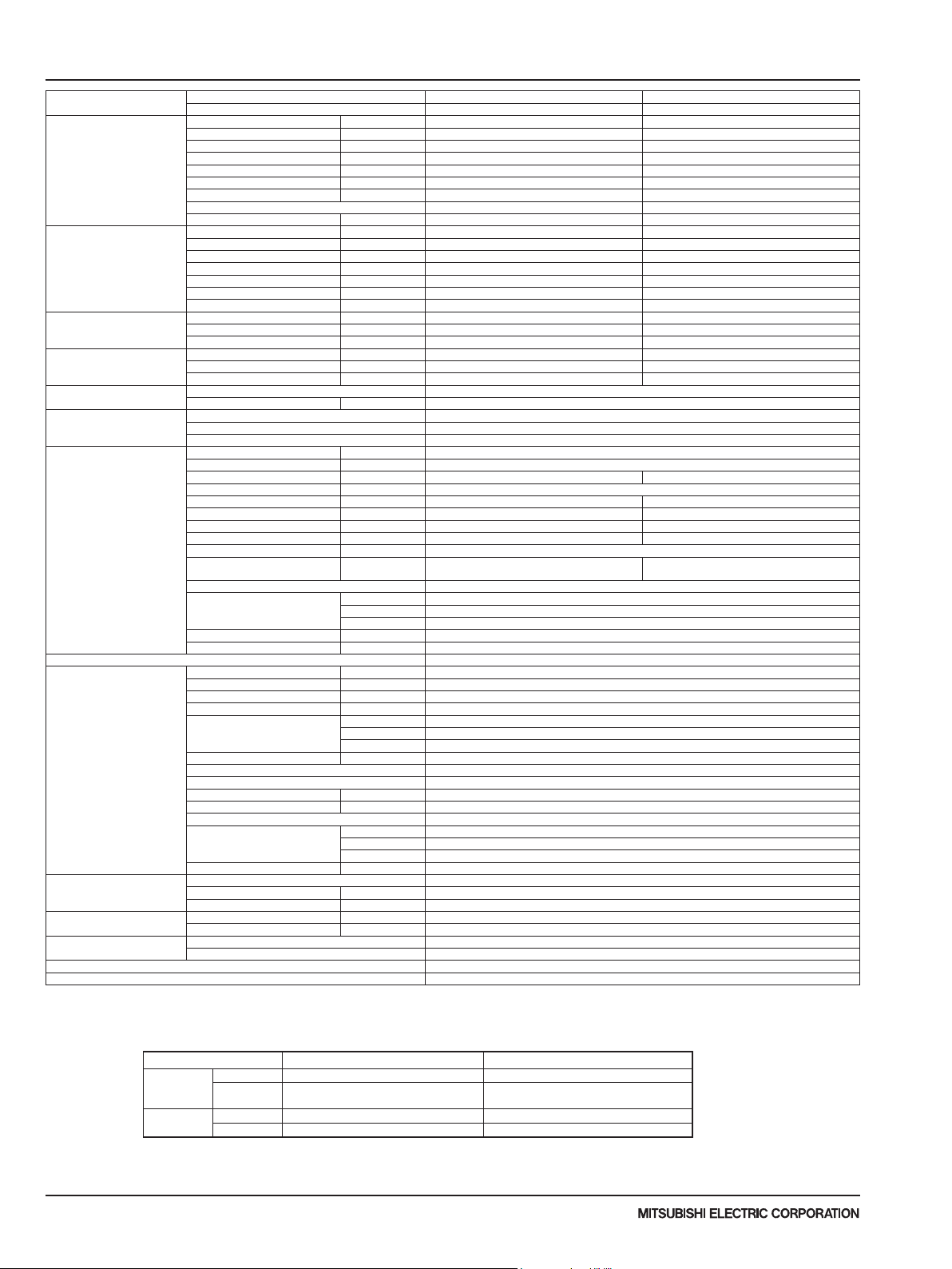
Model name Indoor unit PLA-A12EA7 PLA-A18EA7 PLA-A24EA7 PLA-A30EA7 PLA-A36EA7 PLA-A42EA7
Cooling Max. Capacity Btu/h 12,000 18,000 24,000 30,000 36,000 42,000
Heating Max. Capacity Btu/h 20,000 23,000 29,000 33,000 42,000 48,000
Heating
at low ambient
Power supply Phase,Cycle,Voltage 1phase, 60Hz, 208/230V
Voltage Indoor - Outdoor S1-S2 AC208V / 230V
Indoor unit MCA A 1 2
Remote controller Attached in indoor unit
Outdoor unit MCA A 11 19 25
Refrigerant Type R410A
Refrigerant pipe size Gas side O.D. mm[inch] 12.7[1/2F] 15.88[5/8]
Refrigerant pipe length
Refrigerant piping Not Supplied
Connection Method Flared
NOTES : *1.Rating conditions (cooling)-Indoor : D.B. 26.7°C(80°F), W.B. 19.4°C(67°F) Outdoor : D.B. 35°C(95°F), W.B. 23.9°C(75°F)
(heating)-Indoor : D.B. 21.1°C(70°F), W.B. 15.6°C(60°F) Outdoor : D.B. 8.3°C(47°F), W.B. 6.1°C(43°F)
*2.Rating conditions (heating)-Indoor : D.B. 21.1°C(70°F), W.B. 15.6°C(60°F) Outdoor : D.B. -8.3°C(17°F), W.B. -9.4°C(15°F)
Operating range
Cooling
Heating
* In case that the wind bafe is installed. (In case that the wind bafe is not installed, the minimum temperature will be -5°C(23°F)DB.)
Outdoor unit PUZ-A12NKA7 PUZ-A18NKA7 PUZ-A24NHA7 PUZ-A30NHA7 PUZ-A36NKA7 PUZ-A42NKA7
Rated Capacity Btu/h 12,000 18,000 24,000 30,000 36,000 42,000
Min. Capacity Btu/h 5,800 8,000 10,000 9,000 16,000 16,000
Total Input W 730 1,250 1,670 2,540 2,780 3,590
EER Btu/h/W 16.4 14.4 14.3 11.8 12.9 11.6
SEER Btu/h/W 27.0 24.6 24.2 22.8 21.8 21.0
Moisture Removal Pints/h 1.2 2.4 3.0 5.4 4.5 7.9
SHF 0.89 0.85 0.86 0.80 0.86 0.79
Power factor % 93.4 95.3 94.3 95.2 93.7 94.6
Rated Capacity Btu/h 14,000 19,000 26,000 32,000 38,000 45,000
Min. Capacity Btu/h 5,500 7,900 9,000 9,000 18,000 18,000
Total Input W 830 1,300 1,750 2,400 2,540 3,290
COP W/W 4.94 4.28 4.35 3.90 4.38 4.00
HSPF(IV/V) Btu/h/W 12.8/8.8 11.0/7.8 11.2/8.1 11.6/8.4 10.4/7.6 9.3/7.3
Power factor % 95.0 95.8 95.1 95.7 93.6 94.1
Rated Capacity Btu/h 10,100 11,000 14,900 18,100 22,000 28,000
Total Input W 1,170 1,300 1,600 1,880 2,490 3,070
COP W/W 2.53 2.47 2.72 2.82 2.58 2.67
Breaker size A 15 25 30
Indoor - Outdoor S2-S3 DC24V
Indoor - Remote controller
MOCP A 15
Fan Motor F.L.A 0.36 0.60 0.74 0.95
Fan Motor Output W 50 120 120
Air ow DRY
(Lo-M2-M1-Hi) WET
Air ow DRY
(Lo-M2-M1-Hi) WET
External pressure
Sound level
(Lo-M2-M1-Hi)
External nish White Munsell 6.4Y 8.9/0.4
Dimension
Unit (Panel)
Weight Unit kg 21 25
Field Drain pipe size mm[inch] 32[1-1/4]
MOCP A 28 26 31
Fan Motor F.L.A 0.5 0.4 0.5 + 0.5
Fan Motor Output W 46 86 74
Compressor Type SNB092FNCM SNB130FNCM2 SNB172FWHM1 MNB33FBRMC-L
Air ow CMM[CFM] 45[1,590] 55[1,940] 110[3,880]
Refrigerant Control Electronic Expansion Valve
Defrost Method Reverse Cycle
Sound level at cooling dB(A) 44 47 52
Sound level at heating dB(A) 46 48 53
External nish Ivory Munsell 3Y 7.8/1.1
Dimension W:mm[inch] 809+62 [31-13/16 + 7/16] 950 [37-13/32] 1,050 [41-5/16]
Weight kg[lbs] 42 [93] 45[100] 69[153] 97[214]
Charge kg[lbs,oz] 2.0 [4 lbs 7 oz] 2.2 [4 lbs 14 oz] 3.5 [7 lbs 11 oz] 4.7 [10 lbs 6 oz]
Oil L[oz] 0.35 (FV50S) [12] 0.50 (FV50S) [16] 0.70 (FV50S) [23] 1.40 (FV50S) [45]
Liquid side O.D. mm[inch] 6.35[1/4F] 9.52[3/8]
Height difference Max. 30m [Max.100ft]
Length Max. 30m [Max.100ft] Max. 50m [Max.165ft]
Maximum D.B. 32°C(90°F), W.B. 23°C(73°F) D.B. 46°C(115°F)
Minimum D.B. 19°C(66°F), W.B. 15°C(59°F)
Maximum D.B. 28°C(82°F) D.B. 21°C(70°F), W.B. 15°C(59°F)
Minimum D.B. 10°C(50°F) D.B. -11°C(12°F), W.B. -12°C(10°F)
CMM 12-13-14-15 13-14-16-17 15-18-20-23 16-19-22-25 19-24-29-34 21-26-30-34
CMM 10-11-12-14 11-13-15-17 14-17-19-22 15-18-21-24 18-23-28-33 20-25-29-33
CFM 420-460-490-530 460-490-570-600 530-640-710-810 570-670-780-880 670-850-1,020-1,200740-920-1,060-1,200
CFM 380-420-450-490 420-450-530-560 490-600-670-770 530-630-740-840 630-810-980-1,160 700-880-1,020-1,160
in.WG[Pa]
dB(A) 27-28-29-30 28-29-31-32 28-30-33-36 28-32-35-38 32-37-41-44 34-38-42-45
W:mm[inch] 840(950)[33-3/32(37-13/32)]
D:mm[inch] 840(950)[33-3/32(37-13/32)]
H:mm[inch] 258(40)[10-3/16(1-9/16)] 298(40)[11-3/4(1-9/16)]
R.L.A 7 8
L.R.A 12 11 13
D:mm[inch] 300 [11-3/16] 330 + 30 [13 + 1-3/16]
H:mm[inch] 630 [24-13/16] 943 [37-1/8] 1,338 [52-11/16]
Indoor intake air temperature Outdoor intake air temperature
PUZ-A12NKA7-BS PUZ-A18NKA7-BS PUZ-A24NHA7-BS PUZ-A30NHA7-BS PUZ-A36NKA7-BS PUZ-A42NKA7-BS
DC12V
0
lbs 46 56
D.B.-5°C(23°F)
D.B.-18°C(0°F)*
Due to continuing improvement, above specication may be subject to change without notice.
P-Series (March 2017)
6
© 2017 Mitsubishi Electric US, Inc.
SPECIFICATIONS
2
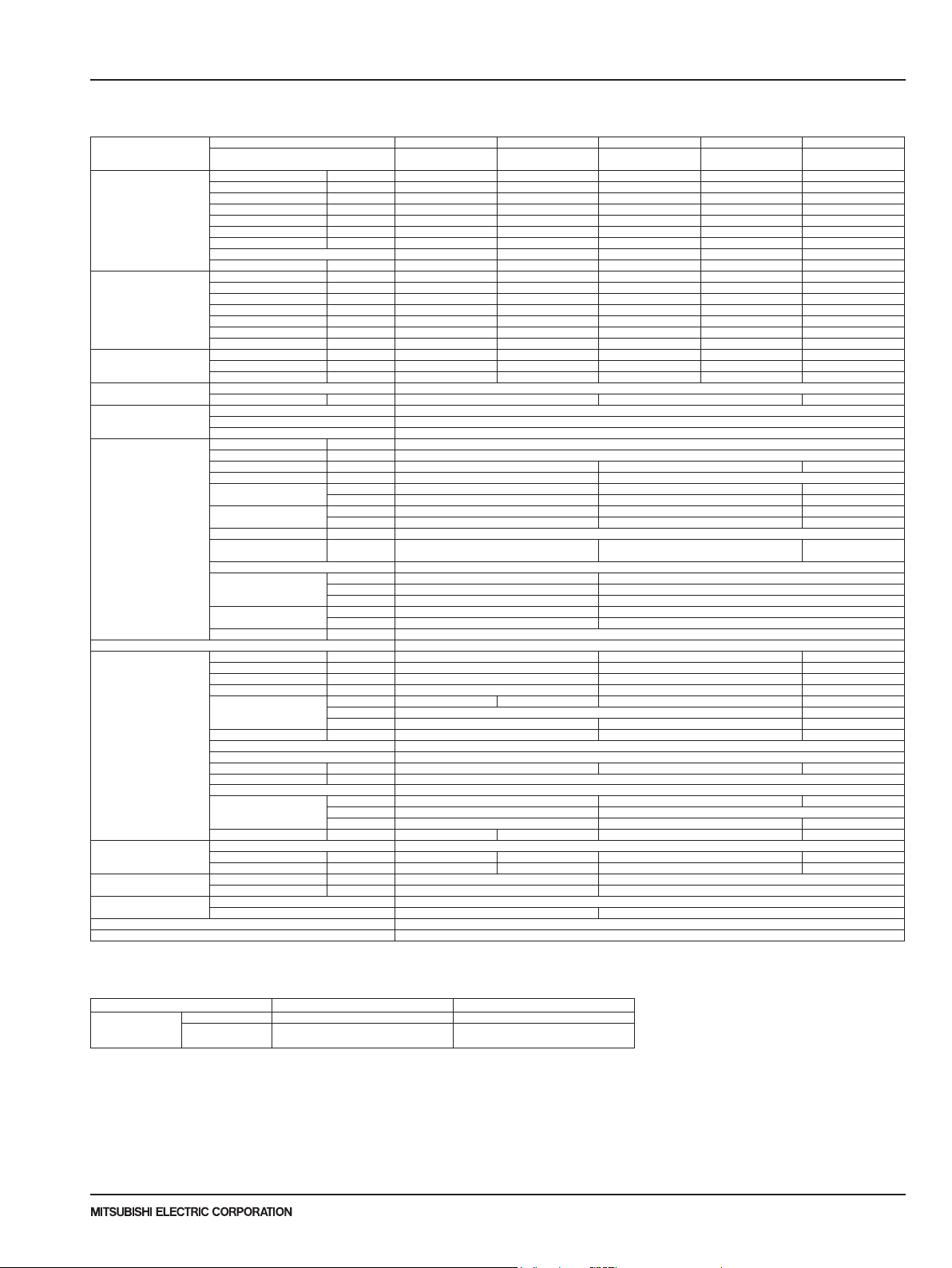
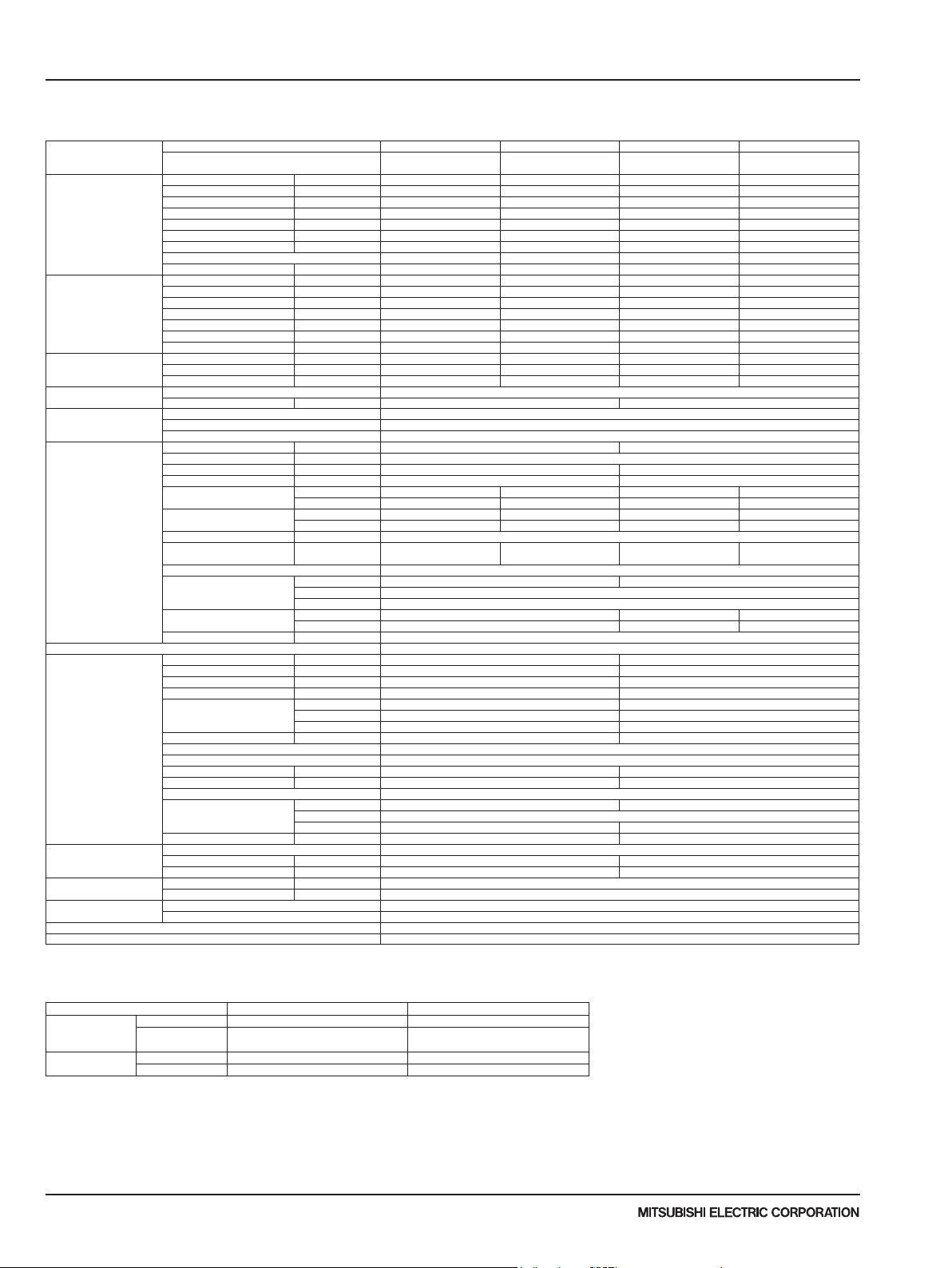
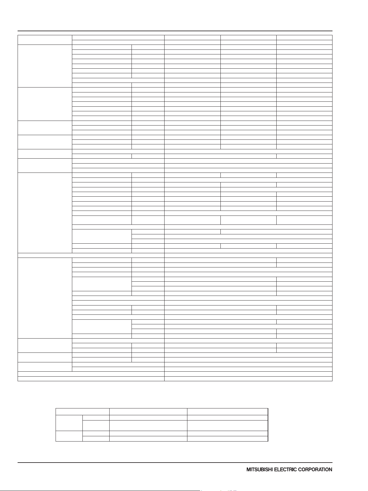
2-2. INVERTER WALL-MOUNTED TYPE (PKA)
Model name Indoor unit PKA-A12HA7 PKA-A18HA7 PKA-A24KA7 PKA-A30KA7 PKA-A36KA7
Cooling Max. Capacity Btu/h 12,000 18,000 24,000 30,000 36,000
Heating Max. Capacity Btu/h - - - - -
Heating
at low ambient
Power supply Phase,Cycle,Voltage 1phase, 60Hz, 208/230V
Voltage Indoor - Outdoor S1-S2 AC208V / 230V
Indoor unit MCA A 1
Remote controller Attached in indoor unit
Outdoor unit MCA A 11 19 25
Refrigerant Type R410A
Refrigerant pipe size Gas side O.D. mm[inch] 12.7[1/2] 15.88[5/8]
Refrigerant pipe length Height difference Max. 30m [Max.100ft]
Refrigerant piping Not Supplied
Connection Method Flared
NOTES : *1.Rating conditions (cooling)-Indoor : D.B. 26.7°C(80°F), W.B. 19.4°C(67°F) Outdoor : D.B. 35°C(95°F), W.B. 23.9°C(75°F)
Outdoor unit PUY-A12NKA7 PUY-A18NKA7 PUY-A24NHA7 PUY-A30NHA7 PUY-A36NKA7
Rated Capacity Btu/h 12,000 18,000 24,000 30,000 36,000
Min. Capacity Btu/h 5,800 8,000 10,000 9,000 16,000
Total Input W 1,000 1,820 1,960 3,150 3,330
EER Btu/h/W 12.0 9.9 12.2 9.5 10.8
SEER Btu/h/W 20.8 18.5 21.4 19.8 18.8
Moisture Removal Pints/h 2.0 5.2 5.0 8.1 9.7
SHF 0.81 0.68 0.77 0.70 0.70
Power factor % 94.5 95.3 95.7 96.4 96.5
Rated Capacity Btu/h - - - - Min. Capacity Btu/h - - - - Total Input W - - - - COP W/W - - - - HSPF(IV/V) Btu/h/W - - - - Power factor % - - - - Rated Capacity Btu/h - - - - Total Input W - - - - COP W/W - - - - -
Breaker size A 15 25 30
Indoor - Outdoor S2-S3 DC24V
Indoor - Remote controller DC12V
MOCP A 15
Fan Motor F.L.A 0.33 0.36 0.57
Fan Motor Output W 30 56
Air ow DRY
(Lo-Mid-Hi) WET
Air ow DRY
(Lo-Mid-Hi) WET
External pressure in.WG[Pa] 0
Sound level
(Lo-Mid-Hi)
External nish White Munsell 1.0Y 9.2/0.2
Dimension
Unit (Panel)
Weight Unit kg 13 21
Field Drain pipe size mm[inch] 16[5/8]
MOCP A 28 26 31
Fan Motor F.L.A 0.5 0.4 0.5 + 0.5
Fan Motor Output W 46 86 74
Compressor Type SNB092FNCM SNB130FNCM2 SNB172FWHM1 MNB33FBRMC-L
Air ow CMM[CFM] 45[1,590] 55[1,940] 110[3,880]
Refrigerant Control Electronic Expansion Valve
Defrost Method Sound level at cooling dB(A) 44 47 52
Sound level at heating dB(A) External nish Ivory Munsell 3Y 7.8/1.1
Dimension W:mm[inch] 809+62 [31-13/16 + 7/16] 950 [37-13/32] 1,050 [41-5/16]
Weight kg[lbs] 41[92] 44[99] 68[151] 96[211]
Charge kg[lbs,oz] 2.0 [4 lbs 7 oz] 2.2 [4 lbs 14 oz] 3.5 [7 lbs 11 oz] 4.7 [10 lbs 6 oz]
Oil L[oz] 0.35 (FV50S) [12] 0.50 (FV50S) [16] 0.70 (FV50S) [23] 1.40 (FV50S) [45]
Liquid side O.D. mm[inch] 6.35[1/4] 9.52[3/8]
Length Max. 50m [Max.165ft] Max. 69m [Max.225ft]
CMM 9-10.5-12 18-20-22 20-23-26
CMM 8-9.5-11 16-18-20 18-21-23
CFM 320-370-425 635-705-775 705-810-920
CFM 290-335-380 570-635-700 635-730-830
dB(A) 36-40-43 39-42-45 43-46-49
W:mm[inch] 898[35-3/8] 1,170[46-1/16]
D:mm[inch] 249[9-13/16] 295[11-5/8]
H:mm[inch] 295[11-5/8] 365[14-3/8]
lbs 29 46
R.L.A 7 8
L.R.A 12 11 13
D:mm[inch] 300 [11-3/16] 330 + 30 [13 + 1-3/16]
H:mm[inch] 630 [24-13/16] 943 [37-1/8] 1,338 [52-11/16]
PUY-A12NKA7-BS PUY-A18NKA7-BS PUY-A24NHA7-BS PUY-A30NHA7-BS PUY-A36NKA7-BS
Operating range
Cooling
* In case that the wind bafe is installed. (In case that the wind bafe is not installed, the minimum temperature will be -5°C(23°F)DB.)
Maximum D.B. 32°C(90°F), W.B. 23°C(73°F) D.B. 46°C(115°F)
Minimum D.B. 19°C(66°F), W.B. 15°C(59°F)
Indoor intake air temperature Outdoor intake air temperature
D.B.-5°C(23°F)
D.B.-28.9°C(-20°F)*
Due to continuing improvement, above specication may be subject to change without notice.
P-Series (March 2017)
© 2017 Mitsubishi Electric US, Inc.
7
2 SPECIFICATIONS
Model name
Cooling Max. Capacity Btu/h 12,000 18,000 24,000 30,000 36,000
Heating Max. Capacity Btu/h 18,000 22,000 28,000 34,000 40,000
Heating
at low ambient
Power supply Phase,Cycle,Voltage 1phase, 60Hz, 208/230V
Voltage Indoor - Outdoor S1-S2 AC208V / 230V
Indoor unit MCA A 1
Remote controller Attached in indoor unit
Outdoor unit MCA A 11 19 25
Refrigerant Type R410A
Refrigerant pipe size Gas side O.D. mm[inch] 12.7[1/2F] 15.88[5/8]
Refrigerant pipe length Height difference Max. 30m [Max.100ft]
Refrigerant piping Not Supplied
Connection Method Flared
NOTES : *1.Rating conditions (cooling)-Indoor : D.B. 26.7°C(80°F), W.B. 19.4°C(67°F) Outdoor : D.B. 35°C(95°F), W.B. 23.9°C(75°F)
(heating)-Indoor : D.B. 21.1°C(70°F), W.B. 15.6°C(60°F) Outdoor : D.B. 8.3°C(47°F), W.B. 6.1°C(43°F)
*2.Rating conditions (heating)-Indoor : D.B. 21.1°C(70°F), W.B. 15.6°C(60°F) Outdoor : D.B. -8.3°C(17°F), W.B. -9.4°C(15°F)
Operating range
Cooling
Heating
* In case that the wind bafe is installed. (In case that the wind bafe is not installed, the minimum temperature will be -5°C(23°F)DB.)
Indoor unit PKA-A12HA7 PKA-A18HA7 PKA-A24KA7 PKA-A30KA7 PKA-A36KA7
Outdoor unit PUZ-A12NKA7 PUZ-A18NKA7 PUZ-A24NHA7 PUZ-A30NHA7 PUZ-A36NKA7
Rated Capacity Btu/h 12,000 18,000 24,000 30,000 36,000
Min. Capacity Btu/h 5,800 8,000 10,000 9,000 16,000
Total Input W 1,000 1,820 1,960 3,150 3,330
EER Btu/h/W 12.0 9.9 12.2 9.5 10.8
SEER Btu/h/W 20.8 18.5 21.4 19.8 18.8
Moisture Removal Pints/h 2.0 5.2 5.0 8.1 9.7
SHF 0.81 0.68 0.77 0.70 0.70
Power factor % 94.5 95.3 95.7 96.4 96.5
Rated Capacity Btu/h 14,000 19,000 26,000 32,000 38,000
Min. Capacity Btu/h 5,500 7,700 9,000 8,900 18,200
Total Input W 950 1,300 1,750 2,460 2,460
COP W/W 4.31 4.28 4.35 3.81 4.52
HSPF(IV/V) Btu/h/W 10.2/7.6 10.2/7.5 11.0/8.2 9.9/7.4 9.2/7.0
Power factor % 93.9 94.2 96.3 96.4 95.5
Rated Capacity Btu/h 9,200 11,300 15,700 18,300 22,400
Total Input W 1,020 1,340 1,750 1,960 2,610
COP W/W 2.64 2.47 2.62 2.73 2.51
Breaker size A 15 25 30
Indoor - Outdoor S2-S3 DC24V
Indoor - Remote controller DC12V
MOCP A 15
Fan Motor F.L.A 0.33 0.36 0.57
Fan Motor Output W 30 56
Air ow DRY
(Lo-Mid-Hi) WET
Air ow DRY
(Lo-Mid-Hi) WET
External pressure in.WG[Pa] 0
Sound level
(Lo-Mid-Hi)
External nish White Munsell 1.0Y 9.2/0.2
Dimension
Unit (Panel)
Weight Unit kg 13 21
Field Drain pipe size mm[inch] 16[5/8]
MOCP A 28 26 31
Fan Motor F.L.A 0.5 0.4 0.5 + 0.5
Fan Motor Output W 46 86 74
Compressor Type SNB092FNCM SNB130FNCM2 SNB172FWHM1 MNB33FBRMC-L
Air ow CMM[CFM] 45[1,590] 55[1,940] 110[3,880]
Refrigerant Control Electronic Expansion Valve
Defrost Method Reverse Cycle
Sound level at cooling dB(A) 44 47 52
Sound level at heating dB(A) 46 48 53
External nish Ivory Munsell 3Y 7.8/1.1
Dimension W:mm[inch] 809+62 [31-13/16 + 7/16] 950 [37-13/32] 1,050 [41-5/16]
Weight kg[lbs] 42 [93] 45[100] 69[153] 97[214]
Charge kg[lbs,oz] 2.0 [4 lbs 7 oz] 2.2 [4 lbs 14 oz] 3.5 [7 lbs 11 oz] 4.7 [10 lbs 6 oz]
Oil L[oz] 0.35 (FV50S) [12] 0.50 (FV50S) [16] 0.70 (FV50S) [23] 1.40 (FV50S) [45]
Liquid side O.D. mm[inch] 6.35[1/4F] 9.52[3/8]
Length Max. 30m [Max.100ft] Max. 50m [Max.165ft]
Maximum D.B. 32°C(90°F), W.B. 23°C(73°F) D.B. 46°C(115°F)
Minimum D.B. 19°C(66°F), W.B. 15°C(59°F)
Maximum D.B. 28°C(82°F) D.B. 21°C(70°F), W.B. 15°C(59°F)
Minimum D.B. 10°C(50°F) D.B. -11°C(12°F), W.B. -12°C(10°F)
Indoor intake air temperature Outdoor intake air temperature
CMM 9-10.5-12 18-20-22 20-23-26
CMM 8-9.5-11 16-18-20 18-21-23
CFM 320-370-425 635-705-775 705-810-920
CFM 290-335-380 570-635-700 635-730-830
dB(A) 36-40-43 39-42-45 43-46-49
W:mm[inch] 898[35-3/8] 1,170[46-1/16]
D:mm[inch] 249[9-13/16] 295[11-5/8]
H:mm[inch] 295[11-5/8] 365[14-3/8]
lbs 29 46
R.L.A 7 8
L.R.A 12 11 13
D:mm[inch] 300 [11-3/16] 330 + 30 [13 + 1-3/16]
H:mm[inch] 630 [24-13/16] 943 [37-1/8] 1,338 [52-11/16]
PUZ-A12NKA7-BS PUZ-A18NKA7-BS PUZ-A24NHA7-BS PUZ-A30NHA7-BS PUZ-A36NKA7-BS
D.B.-5°C(23°F)
D.B.-18°C(0°F)*
Due to continuing improvement, above specication may be subject to change without notice.
P-Series (March 2017)
8
© 2017 Mitsubishi Electric US, Inc.
SPECIFICATIONS
2
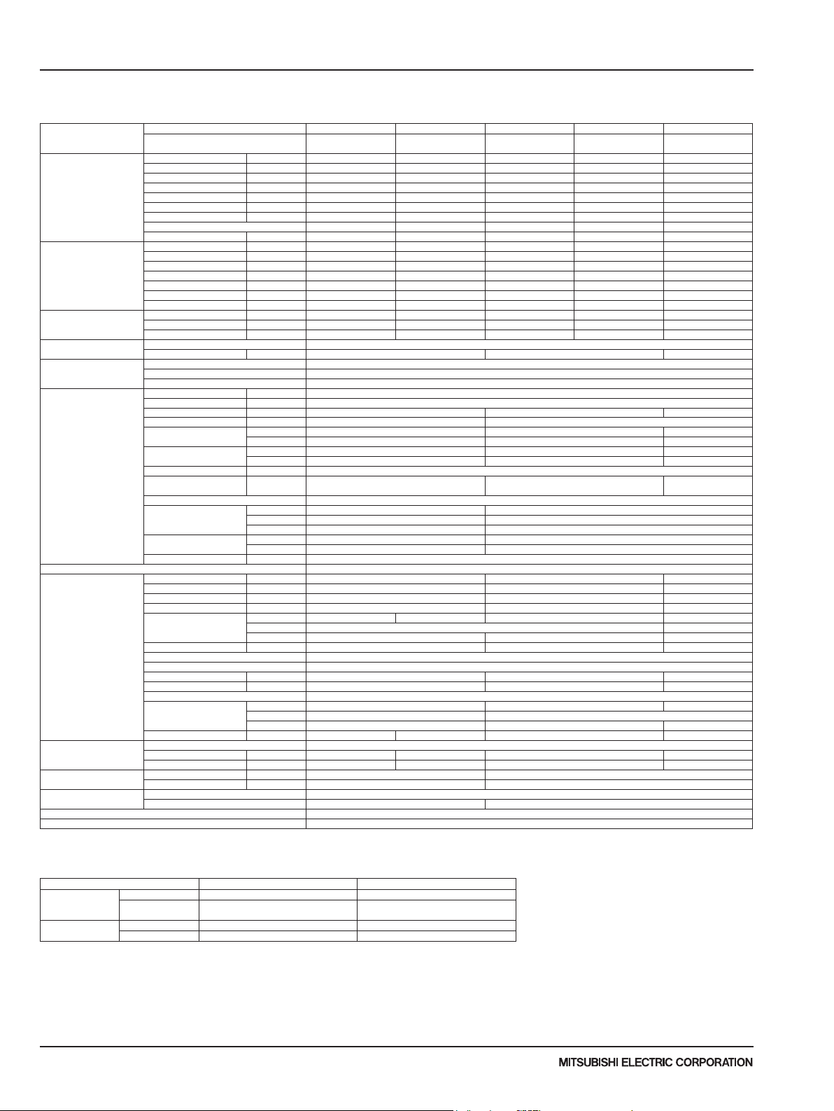
2-3. INVERTER CEILING-SUSPENDED TYPE (PCA)
Model name Indoor unit PCA-A24KA7 PCA-A30KA7 PCA-A36KA7 PCA-A42KA7
Cooling Max. Capacity Btu/h 24,000 30,000 36,000 42,000
Heating Max. Capacity Btu/h - - - -
Heating
at low ambient
Power supply Phase,Cycle,Voltage 1phase, 60Hz, 208/230V
Voltage Indoor - Outdoor S1-S2 AC208V / 230V
Indoor unit MCA A 1 2
Remote controller Attached in Indoor Unit
Outdoor unit MCA A 19 25
Refrigerant Type R410A
Refrigerant pipe size Gas side O.D. mm[inch] 15.88[5/8]
Refrigerant pipe length Height difference Max. 30m [Max.100ft]
Refrigerant piping Not Supplied
Connection Method Flared
NOTES : *1.Rating conditions (cooling)-Indoor : D.B. 26.7°C(80°F), W.B. 19.4°C(67°F) Outdoor : D.B. 35°C(95°F), W.B. 23.9°C(75°F)
Outdoor unit PUY-A24NHA7 PUY-A30NHA7 PUY-A36NKA7 PUY-A42NKA7
Rated Capacity Btu/h 24,000 30,000 36,000 42,000
Min. Capacity Btu/h 10,000 9,000 16,000 16,000
Total Input W 1,960 3,190 3,270 4,110
EER Btu/h/W 12.2 9.4 11.0 10.2
SEER Btu/h/W 21.2 19.6 19.1 17.6
Moisture Removal Pints/h 5.8 8.3 8.7 11.7
SHF 0.73 0.69 0.73 0.69
Power factor % 94.7 96.3 94.2 95.6
Rated Capacity Btu/h - - - Min. Capacity Btu/h - - - Total Input W - - - COP W/W - - - HSPF(IV/V) Btu/h/W - - - Power factor % - - - Rated Capacity Btu/h - - - Total Input W - - - COP W/W - - - -
Breaker size A 25 30
Indoor - Outdoor S2-S3 DC24V
Indoor - Remote controller DC12V
MOCP A 15
Fan Motor F.L.A 0.54 0.97
Fan Motor Output W 95 160
Air ow DRY
(LoLo-Lo-Mid-Hi) WET
Air ow DRY
(LoLo-Lo-Mid-Hi) WET
External pressure in.WG[Pa] 0
Sound level
(LoLo-Lo-Mid-Hi)
External nish White Munsell 6.4Y 8.9/0.4
Dimension
Unit (Panel)
Weight Unit kg 32 36 39
Field Drain pipe size mm[inch] 26[1-1/32]
MOCP A 26 31
Fan Motor F.L.A 0.4 0.5 + 0.5
Fan Motor Output W 86 74
Compressor Type SNB172FWHM1 MNB33FBRMC-L
Air ow CMM[CFM] 55[1,940] 110[3,880]
Refrigerant Control Electronic Expansion Valve
Defrost Method -
Sound level at cooling dB(A) 47 52
Sound level at heating dB(A) 0
External nish Ivory Munsell 3Y 7.8/1.1
Dimension W:mm[inch] 950 [37-13/32] 1,050 [41-5/16]
Weight kg[lbs] 68[151] 96[211]
Charge kg[lbs,oz] 3.5 [7 lbs 11 oz] 4.7 [10 lbs 6 oz]
Oil L[oz] 0.70 (FV50S) [23] 1.40 (FV50S) [45]
Liquid side O.D. mm[inch] 9.52[3/8]
Length Max. 69m [Max.225ft]
CMM 15-16-17-19 16-17-18-20 22-24-26-28 23-25-27-29
CMM 14-15-16-18 15-16-17-19 20-22-24-26 21-23-25-27
CFM 530-565-600-670 565-600-635-705 775-850-920-990 810-885-955-1,025
CFM 495-530-565-635 530-565-600-670 705-775-850-920 740-810-885-955
dB(A) 33-35-37-40 35-37-39-41 37-39-41-43 39-41-43-45
W:mm[inch] 1,280[50-3/8] 1,600[63]
D:mm[inch] 680[26-3/4]
H:mm[inch] 230[9-1/16]
lbs 71 79 86
R.L.A 7 8
L.R.A 11 13
D:mm[inch] 330 + 30 [13 + 1-3/16]
H:mm[inch] 943 [37-1/8] 1,338 [52-11/16]
PUY-A24NHA7-BS PUY-A30NHA7-BS PUY-A36NKA7-BS PUY-A42NKA7-BS
Operating range
Cooling
* In case that the wind bafe is installed. (In case that the wind bafe is not installed, the minimum temperature will be -5°C(23°F)DB.)
Maximum D.B. 32°C(90°F), W.B. 23°C(73°F) D.B. 46°C(115°F)
Minimum D.B. 19°C(66°F), W.B. 15°C(59°F)
Indoor intake air temperature Outdoor intake air temperature
D.B.-5°C(23°F)
D.B.-28.9°C(-20°F)*
Due to continuing improvement, above specication may be subject to change without notice.
P-Series (March 2017)
© 2017 Mitsubishi Electric US, Inc.
9
2 SPECIFICATIONS
Model name Indoor unit PCA-A24KA7 PCA-A30KA7 PCA-A36KA7 PCA-A42KA7
Cooling Max. Capacity Btu/h 24,000 30,000 36,000 42,000
Heating Max. Capacity Btu/h 28,000 34,000 40,000 48,000
Heating
at low ambient
Power supply Phase,Cycle,Voltage 1phase, 60Hz, 208/230V
Voltage Indoor - Outdoor S1-S2 AC208V / 230V
Indoor unit MCA A 1 2
Remote controller Attached in Indoor Unit
Outdoor unit MCA A 19 25
Refrigerant Type R410A
Refrigerant pipe size Gas side O.D. mm[inch] 15.88[5/8]
Refrigerant pipe length Height difference Max. 30m [Max.100ft]
Refrigerant piping Not Supplied
Connection Method Flared
NOTES : *1.Rating conditions (cooling)-Indoor : D.B. 26.7°C(80°F), W.B. 19.4°C(67°F) Outdoor : D.B. 35°C(95°F), W.B. 23.9°C(75°F)
(heating)-Indoor : D.B. 21.1°C(70°F), W.B. 15.6°C(60°F) Outdoor : D.B. 8.3°C(47°F), W.B. 6.1°C(43°F)
*2.Rating conditions (heating)-Indoor : D.B. 21.1°C(70°F), W.B. 15.6°C(60°F) Outdoor : D.B. -8.3°C(17°F), W.B. -9.4°C(15°F)
Operating range
Cooling
Heating
* In case that the wind bafe is installed. (In case that the wind bafe is not installed, the minimum temperature will be -5°C(23°F)DB.)
Outdoor unit PUZ-A24NHA7 PUZ-A30NHA7 PUZ-A36NKA7 PUZ-A42NKA7
Rated Capacity Btu/h 24,000 30,000 36,000 42,000
Min. Capacity Btu/h 10,000 9,000 16,000 16,000
Total Input W 1,960 3,190 3,270 4,110
EER Btu/h/W 12.2 9.4 11.0 10.2
SEER Btu/h/W 21.2 19.6 19.1 17.6
Moisture Removal Pints/h 5.8 8.3 8.7 11.7
SHF 0.73 0.69 0.73 0.69
Power factor % 94.7 96.3 94.2 95.6
Rated Capacity Btu/h 26,000 32,000 38,000 45,000
Min. Capacity Btu/h 8,800 8,600 17,900 18,100
Total Input W 1,800 2,520 2,410 3,480
COP W/W 4.23 3.72 4.62 3.78
HSPF(IV/V) Btu/h/W 10.8/8.1 10.0/7.9 10.2/7.2 10.2/8.2
Power factor % 94.3 96.1 92.7 94.6
Rated Capacity Btu/h 15,400 18,800 21,100 31,800
Total Input W 1,700 2,050 2,430 3,160
COP W/W 2.65 2.68 2.54 2.94
Breaker size A 25 30
Indoor - Outdoor S2-S3 DC24V
Indoor - Remote controller DC12V
MOCP A 15
Fan Motor F.L.A 0.54 0.97
Fan Motor Output W 95 160
Air ow DRY
(Lo-M2-M1-Hi) WET
Air ow DRY
(Lo-M2-M1-Hi) WET
External pressure in.WG[Pa] 0
Sound level
(Lo-M2-M1-Hi)
External nish White Munsell 6.4Y 8.9/0.4
Dimension
Unit (Panel)
Weight Unit kg 32 36 39
Field Drain pipe size mm[inch] 26[1-1/32]
MOCP A 26 31
Fan Motor F.L.A 0.4 0.5 + 0.5
Fan Motor Output W 86 74
Compressor Type SNB172FWHM1 MNB33FBRMC-L
Air ow CMM[CFM] 55[1,940] 110[3,880]
Refrigerant Control Electronic Expansion Valve
Defrost Method Reverse Cycle
Sound level at cooling dB(A) 47 52
Sound level at heating dB(A) 48 53
External nish Ivory Munsell 3Y 7.8/1.1
Dimension W:mm[inch] 950 [37-13/32] 1,050 [41-5/16]
Weight kg[lbs] 69[153] 97[214]
Charge kg[lbs,oz] 3.5 [7 lbs 11 oz] 4.7 [10 lbs 6 oz]
Oil L[oz] 0.70 (FV50S) [23] 1.40 (FV50S) [45]
Liquid side O.D. mm[inch] 9.52[3/8]
Length Max. 50m [Max.165ft]
Maximum D.B. 32°C(90°F), W.B. 23°C(73°F) D.B. 46°C(115°F)
Minimum D.B. 19°C(66°F), W.B. 15°C(59°F)
Maximum D.B. 28°C(82°F) D.B. 21°C(70°F), W.B. 15°C(59°F)
Minimum D.B. 10°C(50°F) D.B. -11°C(12°F), W.B. -12°C(10°F)
Indoor intake air temperature Outdoor intake air temperature
CMM 15-16-17-19 16-17-18-20 22-24-26-28 23-25-27-29
CMM 14-15-16-18 15-16-17-19 20-22-24-26 21-23-25-27
CFM 530-565-600-670 565-600-635-705 775-850-920-990 810-885-955-1,025
CFM 495-530-565-635 530-565-600-670 705-775-850-920 740-810-885-955
dB(A) 33-35-37-40 35-37-39-41 37-39-41-43 39-41-43-45
W:mm[inch] 1,280[50-3/8] 1,600[63]
D:mm[inch] 680[26-3/4]
H:mm[inch] 230[9-1/16]
lbs 71 79 86
R.L.A 7 8
L.R.A 11 13
D:mm[inch] 330 + 30 [13 + 1-3/16]
H:mm[inch] 943 [37-1/8] 1,338 [52-11/16]
PUZ-A24NHA7-BS PUZ-A30NHA7-BS PUZ-A36NKA7-BS PUZ-A42NKA7-BS
D.B.-5°C(23°F)
D.B.-18°C(0°F)*
Due to continuing improvement, above specication may be subject to change without notice.
P-Series (March 2017)
10
© 2017 Mitsubishi Electric US, Inc.
SPECIFICATIONS
2
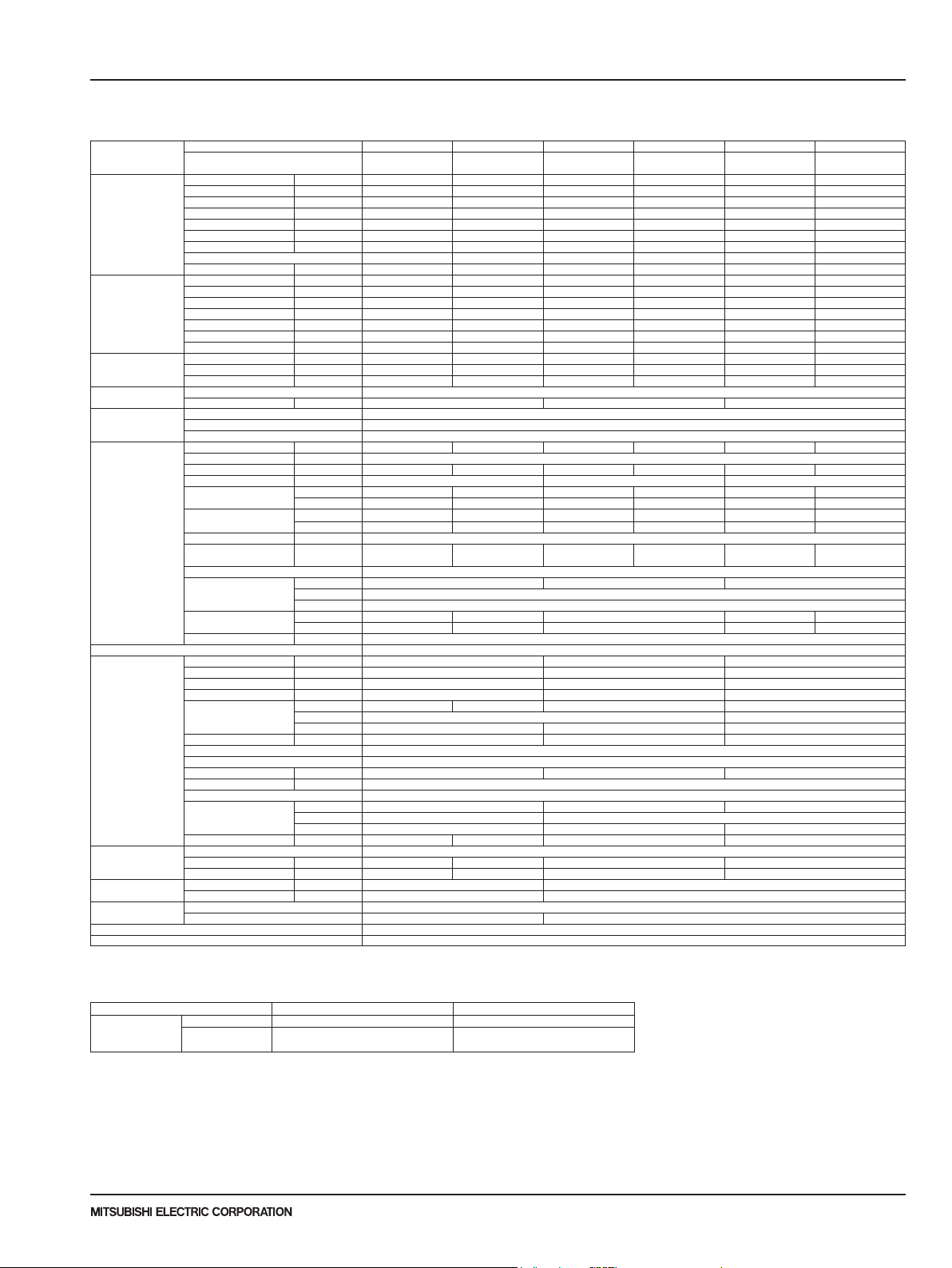
2-4. INVERTER CEILING CONCEALED TYPE (PEAD)
Model name Indoor unit PEAD-A12AA7 PEAD-A18AA7 PEAD-A24AA7 PEAD-A30AA7 PEAD-A36AA7 PEAD-A42AA7
Cooling Max. Capacity Btu/h 12,000 18,000 24,000 30,000 36,000 42,000
Heating Max. Capacity Btu/h - - - - - -
Heating
at low ambient
Power supply Phase,Cycle,Voltage 1phase, 60Hz, 208/230V
Voltage Indoor - Outdoor S1-S2 AC208V / 230V
Indoor unit MCA A 1.45 1.69 2.63 2.73 3.30 3.50
Remote controller Attached in indoor unit
Outdoor unit MCA A 11 19 25
Refrigerant Type R410A
Refrigerant pipe size Gas side O.D. mm[inch] 12.7[1/2] 15.88[5/8]
Refrigerant pipe length
Refrigerant piping Not Supplied
Connection Method Flared
NOTES : *1.Rating conditions (cooling)-Indoor : D.B. 26.7°C(80°F), W.B. 19.4°C(67°F) Outdoor : D.B. 35°C(95°F), W.B. 23.9°C(75°F)
Outdoor unit PUY-A12NKA7 PUY-A18NKA7 PUY-A24NHA7 PUY-A30NHA7 PUY-A36NKA7 PUY-A42NKA7
Rated Capacity Btu/h 12,000 18,000 24,000 30,000 36,000 42,000
Min. Capacity Btu/h 5,000 8,000 10,000 9,000 16,000 16,000
Total Input W 920 1,660 2,050 3,000 3,000 3,920
EER Btu/h/W 13.0 10.8 11.7 10.0 12.0 10.7
SEER Btu/h/W 21.1 19.9 19.6 19.1 19.1 16.1
Moisture Removal Pints/h 1.8 3.7 6.9 8.6 8.1 9
SHF 0.83 0.77 0.68 0.68 0.75 0.76
Power factor % 90.9 91.4 92.8 93.8 93.8 93.6
Rated Capacity Btu/h - - - - - Min. Capacity Btu/h - - - - - Total Input W - - - - - COP W/W - - - - - HSPF(IV/V) Btu/h/W - - - - - Power factor % - - - - - Rated Capacity Btu/h - - - - - Total Input W - - - - - COP W/W - - - - - -
Breaker size A 15 25 30
Indoor - Outdoor S2-S3 DC24V
Indoor - Remote controller DC12V
MOCP A 15
Fan Motor F.L.A 1.16 1.35 2.10 2.18 2.64 2.80
Fan Motor Output W 85 121 244
Air ow DRY
(LoLo-Lo-Mid-Hi) WET
Air ow DRY
(LoLo-Lo-Mid-Hi) WET
External pressure in.WG[Pa] [35/50/70/100/150]
Sound level
(LoLo-Lo-Mid-Hi)
External nish Galvanized
Dimension
Unit (Panel)
Weight Unit kg 26 28 33 41 43
Field Drain pipe size mm[inch] OD. φ32[1-1/4]
MOCP A 28 26 31
Fan Motor F.L.A 0.5 0.4 0.5 + 0.5
Fan Motor Output W 46 86 74
Compressor Type SNB092FNCM SNB130FNCM2 SNB172FWHM1 MNB33FBRMC-L
Air ow CMM[CFM] 45[1,590] 55[1,940] 110[3,880]
Refrigerant Control Electronic Expansion Valve
Defrost Method Sound level at cooling dB(A) 44 47 52
Sound level at heating dB(A) External nish Ivory Munsell 3Y 7.8/1.1
Dimension W:mm[inch] 809+62 [31-13/16 + 7/16] 950 [37-13/32] 1,050 [41-5/16]
Weight kg[lbs] 41[92] 44[99] 68[151] 96[211]
Charge kg[lbs,oz] 2.0 [4 lbs 7 oz] 2.2 [4 lbs 14 oz] 3.5 [7 lbs 11 oz] 4.7 [10 lbs 6 oz]
Oil L[oz] 0.35 (FV50S) [12] 0.50 (FV50S) [16] 0.70 (FV50S) [23] 1.40 (FV50S) [45]
Liquid side O.D. mm[inch] 6.35[1/4] 9.52[3/8]
Height difference Max. 30m [Max.100ft]
Length Max. 50m [Max.165ft] Max. 69m [Max.225ft]
CMM 10.0-12.0-14.0 12.0-14.5-17.0 14.5-18.0-21.0 17.5-21.0-25.0 24.0-29.0-34.0 29.5-35.5-42.0
CMM 9.0-11.0-13.0 11.0-13.5-16.0 13.5-17.0-20.0 16.5-20.0-24.0 23.0-28.0-33.0 28.5-34.5-41.0
CFM 353-424-494 424-512-600 512-635-741 618-742-883 847-1,024-1,201 1,042-1,254-1,483
CFM 313-384-454 384-472-560 472-595-701 578-702-843 807-984-1,161 1,002-1,214-1,443
dB(A) 28-30-34 30-33-37 30-33-37 30-34-39 33-38-42 36-40-44
W:mm[inch] 900[35-7/16] 1,100[43-5/16] 1,400[55-1/8]
D:mm[inch] 732[28-7/8]
H:mm[inch] 250[9-7/8]
R.L.A 7 8
L.R.A 12 11 13
D:mm[inch] 300 [11-3/16] 330 + 30 [13 + 1-3/16]
H:mm[inch] 630 [24-13/16] 943 [37-1/8] 1,338 [52-11/16]
PUY-A12NKA7-BS PUY-A18NKA7-BS PUY-A24NHA7-BS PUY-A30NHA7-BS PUY-A36NKA7-BS PUY-A42NKA7-BS
lbs 58 62 73 91 95
Operating range
Cooling
* In case that the wind bafe is installed. (In case that the wind bafe is not installed, the minimum temperature will be -5°C(23°F)DB.)
Maximum D.B. 32°C(90°F), W.B. 23°C(73°F) D.B. 46°C(115°F)
Minimum D.B. 19°C(66°F), W.B. 15°C(59°F)
Indoor intake air temperature Outdoor intake air temperature
D.B.-5°C(23°F)
D.B.-28.9°C(-20°F)*
Due to continuing improvement, above specication may be subject to change without notice.
P-Series (March 2017)
© 2017 Mitsubishi Electric US, Inc.
11
2 SPECIFICATIONS
Model name Indoor unit PEAD-A12AA7 PEAD-A18AA7 PEAD-A24AA7 PEAD-A30AA7 PEAD-A36AA7 PEAD-A42AA7
Cooling Max. Capacity Btu/h 12,000 18,000 24,000 30,000 36,000 42,000
Heating Max. Capacity Btu/h 18,000 22,000 28,000 34,000 40,000 48,000
Heating
at low ambient
Power supply Phase,Cycle,Voltage 1phase, 60Hz, 208/230V
Voltage Indoor - Outdoor S1-S2 AC208V / 230V
Indoor unit MCA A 1.45 1.69 2.63 2.73 3.30 3.50
Remote controller Attached in indoor unit
Outdoor unit MCA A 11 19 25
Refrigerant Type R410A
Refrigerant pipe size Gas side O.D. mm[inch] 12.7[1/2F] 15.88[5/8]
Refrigerant pipe length
Refrigerant piping Not Supplied
Connection Method Flared
NOTES : *1.Rating conditions (cooling)-Indoor : D.B. 26.7°C(80°F), W.B. 19.4°C(67°F) Outdoor : D.B. 35°C(95°F), W.B. 23.9°C(75°F)
(heating)-Indoor : D.B. 21.1°C(70°F), W.B. 15.6°C(60°F) Outdoor : D.B. 8.3°C(47°F), W.B. 6.1°C(43°F)
*2.Rating conditions (heating)-Indoor : D.B. 21.1°C(70°F), W.B. 15.6°C(60°F) Outdoor : D.B. -8.3°C(17°F), W.B. -9.4°C(15°F)
Operating range
Cooling
Heating
* In case that the wind bafe is installed. (In case that the wind bafe is not installed, the minimum temperature will be -5°C(23°F)DB.)
Outdoor unit PUZ-A12NKA7 PUZ-A18NKA7 PUZ-A24NHA7 PUZ-A30NHA7 PUZ-A36NKA7 PUZ-A42NKA7
Rated Capacity Btu/h 12,000 18,000 24,000 30,000 36,000 42,000
Min. Capacity Btu/h 5,000 8,000 10,000 9,000 16,000 16,000
Total Input W 920 1,660 2,050 3,000 3,000 3,920
EER Btu/h/W 13.0 10.8 11.7 10.0 12.0 10.7
SEER Btu/h/W 21.1 19.9 19.6 19.1 19.1 16.1
Moisture Removal Pints/h 1.8 3.7 6.9 8.6 8.1 9.0
SHF 0.83 0.77 0.68 0.68 0.75 0.76
Power factor % 90.9 91.4 92.8 93.8 93.8 93.6
Rated Capacity Btu/h 14,000 19,000 26,000 32,000 38,000 45,000
Min. Capacity Btu/h 5,800 7,900 9,000 8,800 18,200 18,100
Total Input W 1,030 1,400 1,750 2,490 2,410 3,290
COP W/W 3.98 3.97 4.35 3.76 4.62 4.00
HSPF(IV/V) Btu/h/W 10.2/7.5 10.2/7.6 10.8/8.0 10.8/7.7 9.9/7.3 10.0/7.9
Power factor % 91.4 92.0 92.8 93.3 92.7 92.9
Rated Capacity Btu/h 8,700 11,000 14,800 18,500 20,900 30,600
Total Input W 1,100 1,350 1,630 1,980 2,350 3,040
COP W/W 2.31 2.38 2.66 2.73 2.60 2.95
Breaker size A 15 25 30
Indoor - Outdoor S2-S3 DC24V
Indoor - Remote controller DC12V
MOCP A 15
Fan Motor F.L.A 1.16 1.35 2.10 2.18 2.64 2.80
Fan Motor Output W 85 121 244
Air ow DRY
(Lo-Mid-Hi) WET
Air ow DRY
(Lo-Mid-Hi) WET
External pressure in.WG[Pa] [35/50/70/100/150]
Sound level
(Lo-Mid-Hi)
External nish Galvanized
Dimension
Unit (Panel)
Weight Unit kg 26 28 33 41 43
Field Drain pipe size mm[inch] OD. φ32[1-1/4]
MOCP A 28 26 31
Fan Motor F.L.A 0.5 0.4 0.5 + 0.5
Fan Motor Output W 46 86 74
Compressor Type SNB092FNCM SNB130FNCM2 SNB172FWHM1 MNB33FBRMC-L
Air ow CMM[CFM] 45[1,590] 55[1,940] 110[3,880]
Refrigerant Control Electronic Expansion Valve
Defrost Method Reverse Cycle
Sound level at cooling
Sound level at heating
External nish Ivory Munsell 3Y 7.8/1.1
Dimension W:mm[inch] 809+62 [31-13/16 + 7/16] 950 [37-13/32] 1,050 [41-5/16]
Weight kg[lbs] 42 [93] 45[100] 69[153] 97[214]
Charge kg[lbs,oz] 2.0 [4 lbs 7 oz] 2.2 [4 lbs 14 oz] 3.5 [7 lbs 11 oz] 4.7 [10 lbs 6 oz]
Oil L[oz] 0.35 (FV50S) [12] 0.50 (FV50S) [16] 0.70 (FV50S) [23] 1.40 (FV50S) [45]
Liquid side O.D. mm[inch] 6.35[1/4F] 9.52[3/8]
Height difference Max. 30m [Max.100ft]
Length Max. 30m [Max.100ft] Max. 50m [Max.165ft]
Maximum D.B. 32°C(90°F), W.B. 23°C(73°F) D.B. 46°C(115°F)
Minimum D.B. 19°C(66°F), W.B. 15°C(59°F)
Maximum D.B. 28°C(82°F) D.B. 21°C(70°F), W.B. 15°C(59°F)
Minimum D.B. 10°C(50°F) D.B. -11°C(12°F), W.B. -12°C(10°F)
CMM 10.0-12.0-14.0 12.0-14.5-17.0 14.5-18.0-21.0 17.5-21.0-25.0 24.0-29.0-34.0 29.5-35.5-42.0
CMM 9.0-11.0-13.0 11.0-13.5-16.0 13.5-17.0-20.0 16.5-20.0-24.0 23.0-28.0-33.0 28.5-34.5-41.0
CFM 353-424-494 424-512-600 512-635-741 618-742-883 847-1,024-1,201 1,042-1,254-1,483
CFM 313-384-454 384-472-560 472-595-701 578-702-843 807-984-1,161 1,002-1,214-1,443
dB(A) 28-30-34 30-33-37 30-33-37 30-34-39 33-38-42 36-40-44
W:mm[inch] 900[35-7/16] 1,100[43-5/16] 1,400[55-1/8]
D:mm[inch] 732[28-7/8]
H:mm[inch] 250[9-7/8]
lbs 58 62 73 91 95
R.L.A 7 8
L.R.A 12 11 13
dB(A) 44 47 52
dB(A) 46 48 53
D:mm[inch] 300 [11-3/16] 330 + 30 [13 + 1-3/16]
H:mm[inch] 630 [24-13/16] 943 [37-1/8] 1,338 [52-11/16]
Indoor intake air temperature Outdoor intake air temperature
PUZ-A12NKA7-BS PUZ-A18NKA7-BS PUZ-A24NHA7-BS PUZ-A30NHA7-BS PUZ-A36NKA7-BS PUZ-A42NKA7-BS
D.B.-5°C(23°F)
D.B.-18°C(0°F)*
Due to continuing improvement, above specication may be subject to change without notice.
P-Series (March 2017)
12
© 2017 Mitsubishi Electric US, Inc.

SPECIFICATIONS
2
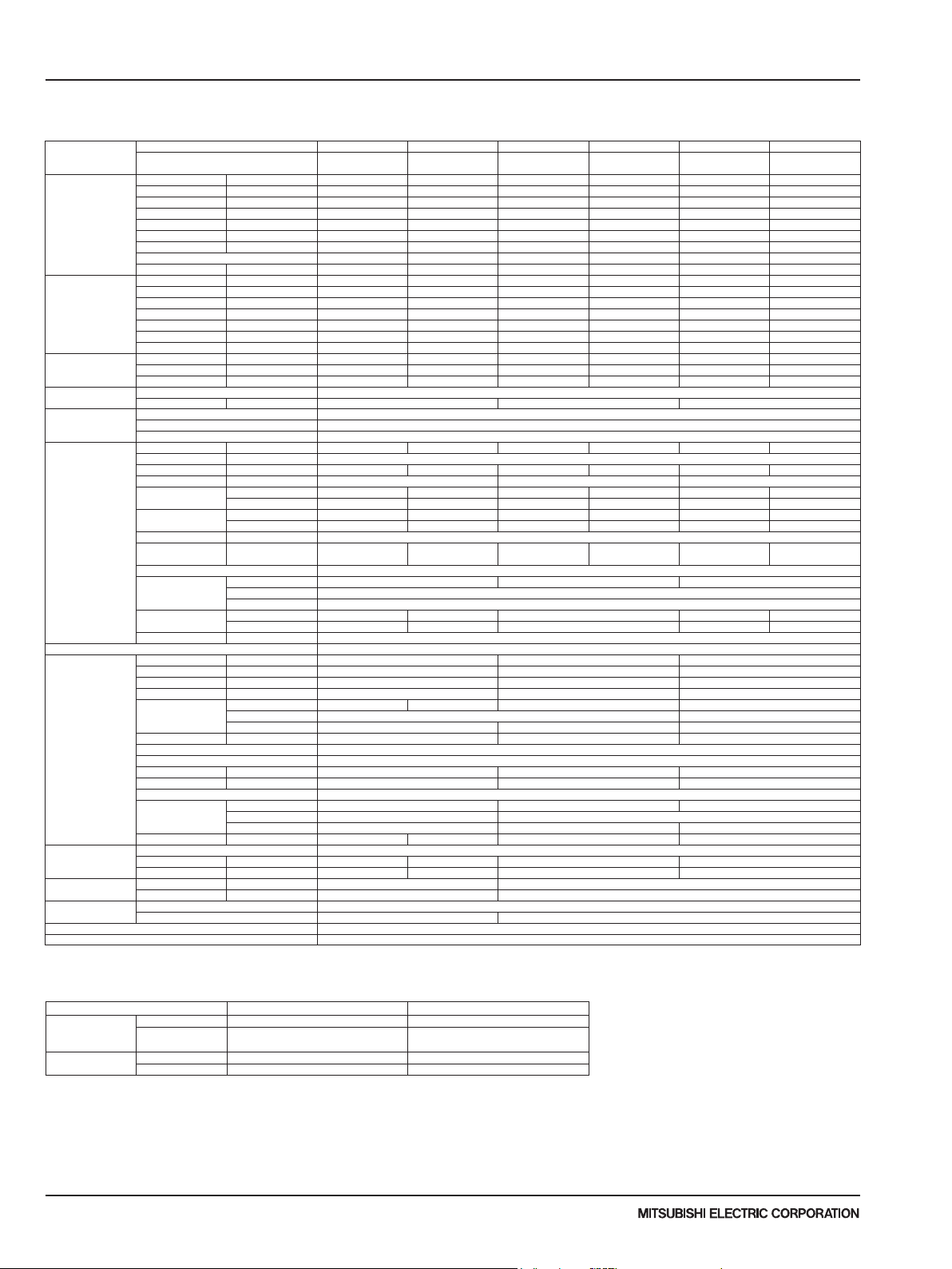
2-5. INVERTER MULTI POSITION TYPE (PVA)
Model name Indoor unit PVA-A12AA7 PVA-A18AA7 PVA-A24AA7 PVA-A30AA7 PVA-A36AA7 PVA-A42AA7
Cooling Max. Capacity Btu/h 12,000 18,000 24,000 30,000 36,000 42,000
Heating Max. Capacity Btu/h - - - - - -
Heating
at low ambient
Power supply Phase,Cycle,Voltage 1phase, 60Hz, 208/230V
Voltage Indoor - Outdoor S1-S2 AC208V / 230V
Indoor unit MCA A 3.00 4.13 5.50 5.63
Remote controller Attached in indoor unit
Outdoor unit MCA A 11 19 25
Refrigerant Type R410A
Refrigerant pipe size Gas side O.D. mm[inch] 12.7[1/2] 15.88[5/8]
Refrigerant pipe length
Refrigerant piping Not Supplied
Connection Method Flared
NOTES : *1.Rating conditions (cooling)-Indoor : D.B. 26.7°C(80°F), W.B. 19.4°C(67°F) Outdoor : D.B. 35°C(95°F), W.B. 23.9°C(75°F)
Outdoor unit PUY-A12NKA7 PUY-A18NKA7 PUY-A24NHA7 PUY-A30NHA7 PUY-A36NKA7 PUY-A42NKA7
Rated Capacity Btu/h 12,000 18,000 24,000 30,000 36,000 42,000
Min. Capacity Btu/h 4,800 7,000 10,000 10,000 14,600 15,000
Total Input W 890 1,570 1,960 3,000 3,250 4,150
EER Btu/h/W 13.4 11.4 12.2 10.0 9.8 10.1
SEER Btu/h/W 21.4 20.2 20.5 19.0 19.3 18.0
Moisture Removal Pints/h 1.2 2.4 3 5.4 4.5 7.9
SHF 0.77 0.76 0.83 0.74 0.77 0.81
Power factor % 87.9 89.8 89.7 93.2 88.3 87.6
Rated Capacity Btu/h - - - - - Min. Capacity Btu/h - - - - - Total Input W - - - - - COP W/W - - - - - HSPF(IV/V) Btu/h/W - - - - - Power factor % - - - - - Rated Capacity Btu/h - - - - - Total Input W - - - - - COP W/W - - - - - -
Breaker size A 15 25 30
Indoor - Outdoor S2-S3 DC24V
Indoor - Remote controller DC12V
MOCP A 15
Fan Motor F.L.A 2.4 3.3 4.4 4.5
Fan Motor Output W 121 244 430
Air ow DRY
(LoLo-Lo-Mid-Hi) WET
Air ow DRY
(LoLo-Lo-Mid-Hi) WET
External pressure in.WG[Pa] <75>-125-<200>
Sound level
(LoLo-Lo-Mid-Hi)
External nish Galvanized steel cabinet-Powder coated Slate Gray
Dimension
Unit (Panel)
Weight Unit kg 51 64 78
Field Drain pipe size mm[inch] 19.05[3/4] FPT
MOCP A 28 26 31
Fan Motor F.L.A 0.5 0.4 0.5 + 0.5
Fan Motor Output W 46 86 74
Compressor Type SNB092FNCM SNB130FNCM2 SNB172FWHM1 MNB33FBRMC-L
Air ow CMM[CFM] 45[1,590] 55[1,940] 110[3,880]
Refrigerant Control Electronic Expansion Valve
Defrost Method Sound level at cooling dB(A) 44 47 52
Sound level at heating dB(A) External nish Ivory Munsell 3Y 7.8/1.1
Dimension W:mm[inch] 809+62 [31-13/16 + 7/16] 950 [37-13/32] 1,050 [41-5/16]
Weight kg[lbs] 41[92] 44[99] 68[151] 96[211]
Charge kg[lbs,oz] 2.0 [4 lbs 7 oz] 2.2 [4 lbs 14 oz] 3.5 [7 lbs 11 oz] 4.7 [10 lbs 6 oz]
Oil L[oz] 0.35 (FV50S) [12] 0.50 (FV50S) [16] 0.70 (FV50S) [23] 1.40 (FV50S) [45]
Liquid side O.D. mm[inch] 6.35[1/4] 9.52[3/8]
Height difference Max. 30m [Max.100ft]
Length Max. 50m [Max.165ft] Max. 69m [Max.225ft]
75Pa dB(A) 24-28-32 28-33-36 30-34-38 30-34-38 34-38-42
125Pa dB(A) 27-31-35 30-34-38 32-36-40 32-36-40 36-40-44
200Pa dB(A) 32-36-42 34-38-42 35-39-43 37-42-45 39-43-47
CMM 7.9-9.6-11.3 14.6-17.7-20.8 17.3-21.1-24.8 22.3-27.1-31.9 29.4-35.7-42.0
CMM
CFM 280-340-400 515-625-735 613-744-875 788-956-1,125 1,040-1,262-1,485
CFM
W:mm[inch] 432[17] 534[21] 635[25]
D:mm[inch] 548[21-5/8]
H:mm[inch] 1,275[50-1/4] 1,378[54-1/4] 1,511[59-1/2]
R.L.A 7 8
L.R.A 12 11 13
D:mm[inch] 300 [11-3/16] 330 + 30 [13 + 1- 3/16]
H:mm[inch] 630 [24-13/16] 943 [37-1/8] 1,338 [52-11/16]
PUY-A12NKA7-BS PUY-A18NKA7-BS PUY-A24NHA7-BS PUY-A30NHA7-BS PUY-A36NKA7-BS PUY-A42NKA7-BS
lbs 113 141 172
Operating range
Cooling
* In case that the wind bafe is installed. (In case that the wind bafe is not installed, the minimum temperature will be -5°C(23°F)DB.)
Maximum D.B. 32°C(90°F), W.B. 23°C(73°F) D.B. 46°C(115°F)
Minimum D.B. 19°C(66°F), W.B. 15°C(59°F)
Indoor intake air temperature Outdoor intake air temperature
D.B.-5°C(23°F)
D.B.-28.9°C(-20°F)*
Due to continuing improvement, above specication may be subject to change without notice.
P-Series (March 2017)
© 2017 Mitsubishi Electric US, Inc.
13

2 SPECIFICATIONS
Model name Indoor unit PVA-A12AA7 PVA-A18AA7 PVA-A24AA7 PVA-A30AA7 PVA-A36AA7 PVA-A42AA7
Cooling Max. Capacity Btu/h 12,000 18,000 24,000 30,000 36,000 42,000
Heating Max. Capacity Btu/h 19,000 23,000 28,000 34,000 42,000 48,000
Heating
at low ambient
Power supply Phase,Cycle,Voltage 1phase, 60Hz, 208/230V
Voltage Indoor - Outdoor S1-S2 AC208V / 230V
Indoor unit MCA A 3.00 4.13 5.50 5.63
Remote controller Attached in indoor unit
Outdoor unit MCA A 11 19 25
Refrigerant Type R410A
Refrigerant pipe size Gas side O.D. mm[inch] 12.7[1/2F] 15.88[5/8]
Refrigerant pipe length
Refrigerant piping Not Supplied
Connection Method Flared
NOTES : *1.Rating conditions (cooling)-Indoor : D.B. 26.7°C(80°F), W.B. 19.4°C(67°F) Outdoor : D.B. 35°C(95°F), W.B. 23.9°C(75°F)
(heating)-Indoor : D.B. 21.1°C(70°F), W.B. 15.6°C(60°F) Outdoor : D.B. 8.3°C(47°F), W.B. 6.1°C(43°F)
*2.Rating conditions (heating)-Indoor : D.B. 21.1°C(70°F), W.B. 15.6°C(60°F) Outdoor : D.B. -8.3°C(17°F), W.B. -9.4°C(15°F)
Operating range
Cooling
Heating
* In case that the wind bafe is installed. (In case that the wind bafe is not installed, the minimum temperature will be -5°C(23°F)DB.)
Outdoor unit PUZ-A12NKA7 PUZ-A18NKA7 PUZ-A24NHA7 PUZ-A30NHA7 PUZ-A36NKA7 PUZ-A42NKA7
Rated Capacity Btu/h 12,000 18,000 24,000 30,000 36,000 42,000
Min. Capacity Btu/h 4,800 7,000 10,000 10,000 14,600 15,000
Total Input W 890 1,570 1,960 3,000 3,250 4,150
EER Btu/h/W 13.4 11.4 12.2 10.0 9.8 10.1
SEER Btu/h/W 21.4 20.2 20.5 19.0 19.3 18.0
Moisture Removal Pints/h 1.2 2.4 3 5.4 4.5 7.9
SHF 0.77 0.76 0.83 0.74 0.77 0.81
Power factor % 87.9 89.8 89.7 93.2 88.3 87.6
Rated Capacity Btu/h 14,000 19,000 26,000 32,000 38,000 46,000
Min. Capacity Btu/h 5,700 7,700 12,000 12,000 17,700 18,100
Total Input W 1,070 1,470 1,920 2,640 3,030 3,900
COP W/W 3.83 3.78 3.96 3.55 3.67 3.45
HSPF(IV/V) Btu/h/W 10.3/7.8 10.4/7.6 9.3/7.0 10.0/7.5 9.5/7.3 9.3/7.3
Power factor % 96.4 96.2 96.6 96.8 96.0 95.4
Rated Capacity Btu/h 9,900 12,000 15,000 18,000 24,000 28,500
Total Input W 1,400 1,520 1,760 2,110 2,990 3,440
COP W/W 2.07 2.31 2.49 2.50 2.35 2.42
Breaker size A 15 25 30
Indoor - Outdoor S2-S3 DC24V
Indoor - Remote controller DC12V
MOCP A 15
Fan Motor F.L.A 2.4 3.3 4.4 4.5
Fan Motor Output W 121 244 430
Air ow DRY(Lo-Mid-Hi) CMM 7.9-9.6-11.3 14.6-17.7-20.8 17.3-21.1-24.8 22.3-27.1-31.9 29.4-35.7-42.0
Air ow WET(Lo-Mid-Hi) CMM
Air ow DRY(Lo-Mid-Hi) CFM 280-340-400 515-625-735 613-744-875 788-956-1,125 1,040-1,262-1,485
Air ow WET(Lo-Mid-Hi) CFM
External pressure in.WG[Pa] <75>-125-<200>
Sound level
(Lo-Mid-Hi)
External nish Galvanized steel cabinet-Powder coated Slate Gray
Dimension
Unit (Panel)
Weight Unit kg 51 64 78
Field Drain pipe size mm[inch] 19.05[3/4] FPT
MOCP A 28 26 31
Fan Motor F.L.A 0.5 0.4 0.5 + 0.5
Fan Motor Output W 46 86 74
Compressor Type SNB092FNCM SNB130FNCM2 SNB172FWHM1 MNB33FBRMC-L
Air ow CMM[CFM] 45[1,590] 55[1,940] 110[3,880]
Refrigerant Control Electronic Expansion Valve
Defrost Method Reverse Cycle
Sound level at cooling dB(A) 44 47 52
Sound level at heating dB(A) 46 48 53
External nish Ivory Munsell 3Y 7.8/1.1
Dimension W:mm[inch] 809+62 [31-13/16 + 7/16] 950 [37-13/32] 1,050 [41-5/16]
Weight kg[lbs] 42 [93] 45[100] 69[153] 97[214]
Charge kg[lbs,oz] 2.0 [4 lbs 7 oz] 2.2 [4 lbs 14 oz] 3.5 [7 lbs 11 oz] 4.7 [10 lbs 6 oz]
Oil L[oz] 0.35 (FV50S) [12] 0.50 (FV50S) [16] 0.70 (FV50S) [23] 1.40 (FV50S) [45]
Liquid side O.D. mm[inch] 6.35[1/4F] 9.52[3/8]
Height difference Max. 30m [Max.100ft]
Length Max. 30m [Max.100ft] Max. 50m [Max.165ft]
Maximum D.B. 32°C(90°F), W.B. 23°C(73°F) D.B. 46°C(115°F)
Minimum D.B. 19°C(66°F), W.B. 15°C(59°F)
Maximum D.B. 28°C(82°F) D.B. 21°C(70°F), W.B. 15°C(59°F)
Minimum D.B. 10°C(50°F) D.B. -11°C(12°F), W.B. -12°C(10°F)
75Pa dB(A) 24-28-32 28-33-36 30-34-38 30-34-38 34-38-42
125Pa dB(A) 27-31-35 30-34-38 32-36-40 32-36-40 36-40-44
200Pa dB(A) 32-36-42 34-38-42 35-39-43 37-42-45 39-43-47
W:mm[inch] 432[17] 534[21] 635[25]
D:mm[inch] 548[21-5/8]
H:mm[inch] 1,275[50-1/4] 1,378[54-1/4] 1,511[59-1/2]
R.L.A 7 8
L.R.A 12 11 13
D:mm[inch] 300 [11-3/16] 330 + 30 [13 + 1-3/16]
H:mm[inch] 630 [24-13/16] 943 [37-1/8] 1,338 [52-11/16]
Indoor intake air temperature Outdoor intake air temperature
PUZ-A12NKA7-BS PUZ-A18NKA7-BS PUZ-A24NHA7-BS PUZ-A30NHA7-BS PUZ-A36NKA7-BS PUZ-A42NKA7-BS
lbs 113 141 172
D.B.-5°C(23°F)
D.B.-18°C(0°F)*
Due to continuing improvement, above specication may be subject to change without notice.
P-Series (March 2017)
14
© 2017 Mitsubishi Electric US, Inc.
SPECIFICATIONS
2
2-6. HYPER HEATING INVERTER
Model name Indoor unit PLA-A30EA7 PLA-A36EA7 PLA-A42EA7
Cooling Max. Capacity Btu/h 30,000 36,000 42,000
Heating Max. Capacity Btu/h 34,000 40,000 54,000
Heating at 17°F
(-8.3°C)
Heating at 5°F
(-15°C)
Power supply Phase, Cycle, Voltage 1phase, 60Hz, 208/230V
Voltage Indoor - Outdoor S1-S2 AC208/230V
Indoor unit MCA A 1 2
Remote Controller Attached in indoor unit
Outdoor unit MCA A 28 37
Refrigerant Type R410A
Refrigerant pipe
size
Refrigerant pipe
length
Refrigerant Piping Not Supplied
Connection Method Flared
NOTES : *1.Rating conditions (cooling)-Indoor : D.B. 26.7°C(80°F), W.B. 19.4°C(67°F) Outdoor : D.B. 35°C(95°F), W.B. 23.9°C(75°F)
(heating)-Indoor : D.B. 21.1°C(70°F), W.B. 15.6°C(60°F) Outdoor : D.B. 8.3°C(47°F), W.B. 6.1°C(43°F)
*2.Conditions (heating)-Indoor : D.B. 21.1°C(70°F), W.B. 15.6°C(60°F) Outdoor : D.B. -8.3°C(17°F), W.B. -9.4°C(15°F)
*3.Conditions (heating)-Indoor : D.B. 21.1°C(70°F), W.B. 15.6°C(60°F) Outdoor : D.B. -15°C(5°F), W.B. -15°C(5°F)
Operating range
* In case that the wind baffle is installed. (In case that the wind baffle is not installed, the minimum temperature will be -5°C(23°F)DB.)
Due to continuing improvement, above specication may be subject to change without notice.
© 2017 Mitsubishi Electric US, Inc.
Outdoor unit PUZ-HA30NHA5 PUZ-HA36NHA5 PUZ-HA42NKA
Rated Capacity Btu/h 30,000 36,000 42,000
Min. Capacity Btu/h 18,000 18,000 19,000
Total Input W 2,400 2,850 4,160
EER Btu/h/W 12.5 12.6 10.1
SEER Btu/h/W 15.6 17.0 14.8
Moisture Removal Pints/h 7.2 7.1 10.9
SHF 0.73 0.71 0.71
*1 Power factor % 94.9 93.9 94.7
Rated Capacity Btu/h 32,000 38,000 48,000
Min. Capacity Btu/h 18,000 18,000 21,000
Total Input W 3,330 3,130 4,560
COP W/W 2.81 3.55 3.08
HSPF (IV/V) Btu/h/W 9.6/7.3 10.2/8.2 10.1/8.4
*1 Power factor % 96.5 95.5 96.5
Max. Capacity Btu/h 32,000 38,000 48,000
Total Input W 5,720 5,300 7,100
*2 COP W/W 1.69 2.12 1.98
Max. Capacity Btu/h 32,000 38,000 48,000
Total Input W 6,460 5,790 7,770
*3 COP W/W 1.45 1.92 1.81
Breaker size A 30 40
Indoor - Outdoor S2-S3 DC24V
Indoor - Remote Controller DC12V
MOCP A 15
Fan motor F.L.A. 0.74 0.95
Fan motor output W 120
Air ow DRY(Lo-M2-M1-Hi) CMM 16.0-19.0-22.0-25.0 19.0-24.0-29.0-34.0 21.0-26.0-30.0-34.0
Air ow WET(Lo-M2-M1-Hi) CMM 15.0-18.0-21.0-24.0 18.0-23.0-28.0-33.0 20.0-25.0-29.0-33.0
Air ow DRY(Lo-M2-M1-Hi) CFM 570-670-780-880 670-850-1,020-1,200 740-920-1,060-1,200
Air ow WET(Lo-M2-M1-Hi) CFM 530-630-740-840 630-810-980-1,160 700-880-1,020-1,160
External pressure in.WG [Pa] 0
Sound level
(Lo-M2-M1-Hi)
External nish (panel) White Munsell 6.4Y 8.9/0.4
Dimension Unit (panel) W: mm [inch] 840 (950) [33-3/32 (37-13/32)]
Weight Unit(panel) kg[lbs] 25 (5) [56 (11)]
Field drain pipe size O.D. mm[inch] 32 [1-1/4]
MOCP A 40 44
Fan motor F.L.A. 0.4 + 0.4
Fan motor output W 86 + 86
Compressor Type ANB33FJEMT ANB42FJTMT
Air ow CMM [CFM] 100 [3,530] 94 [3,320]
Refrigerant Control Electronic Expansion Valve
Defrost Method Reverse cycle
Sound level at cooling dB(A) 52 49
Sound level at heating dB(A) 53 51
External nish Munsell 3Y 7.8/1.1
Dimension Unit W: mm [inch] 950 [37-3/8] 1,050 [41-6/16]
Weight Unit kg[lbs] 120 [265] 130 [287]
Charge kg [lbs,oz] 5.5 [12lbs 2oz] 6.0 [13lbs 4oz]
Oil L [oz] 1.4(FV50S) [45] 1.7(FVC68D) [54]
Gas side O.D. mm [inch] 15.88 [5/8]
Liquid side O.D. mm [inch] 9.52 [3/8]
Height difference IU-OU Max. 30m [Max.100ft]
Length Max. 75m [Max.245ft]
Indoor intake air temperature
Cooling
Heating
Maximum
Minimum
Maximum
Minimum
D.B. 32°C(90°F), W.B. 23°C(73°F)
D.B. 19°C(66°F), W.B. 15°C(59°F)
dB(A) 28-32-35-38 32-37-41-44 34-38-41-45
D: mm [inch] 840 (950) [33-3/32 (37-13/32)]
H: mm [inch] 298 (40) [11-3/4 (1-9/16)]
R.L.A. 18.0 19.0
L.R.A. 27.5 28.0
D: mm [inch] 300+30 [13 + 1-3/16]
H: mm [inch] 1,350 [53-1/8] 1,338 [52-11/16]
Outdoor intake air temperature
D.B. 46°C(115°F)
D.B. -5°C(23°F)
D.B. -18°C(0°F)*
D.B. 28°C(83°F)
D.B. 10°C(50°F)
D.B. 21.1°C(70°F), W.B. 15°C(59°F)
D.B. -25°C(-13°F), W.B. -25°C(-13°F)
P-Series (March 2017)
15
2 SPECIFICATIONS
Model name Indoor unit PKA-A30EA7 PKA-A36EA7
Cooling Max. Capacity Btu/h 30,000 34,200
Heating Max. Capacity Btu/h 34,000 40,000
Heating at 17°F
(-8.3°C)
Heating at 5°F
(-15°C)
Power supply Phase, Cycle, Voltage 1phase, 60Hz, 208/230V
Voltage Indoor - Outdoor S1-S2 AC208/230V
Indoor unit MCA A 1
Remote Controller Attached in indoor unit
Outdoor unit MCA A 28
Refrigerant Type R410A
Refrigerant pipe
size
Refrigerant pipe
length
Refrigerant Piping Not Supplied
Connection Method Flared
NOTES : *1.Rating conditions (cooling)-Indoor : D.B. 26.7°C(80°F), W.B. 19.4°C(67°F) Outdoor : D.B. 35°C(95°F), W.B. 23.9°C(75°F)
(heating)-Indoor : D.B. 21.1°C(70°F), W.B. 15.6°C(60°F) Outdoor : D.B. 8.3°C(47°F), W.B. 6.1°C(43°F)
*2.Conditions (heating)-Indoor : D.B. 21.1°C(70°F), W.B. 15.6°C(60°F) Outdoor : D.B. -8.3°C(17°F), W.B. -9.4°C(15°F)
*3.Conditions (heating)-Indoor : D.B. 21.1°C(70°F), W.B. 15.6°C(60°F) Outdoor : D.B. -15°C(5°F), W.B. -15°C(5°F)
Operating range
* In case that the wind baffle is installed. (In case that the wind baffle is not installed, the minimum temperature will be -5°C(23°F)DB.)
Outdoor unit PUZ-HA30NHA5 PUZ-HA36NHA5
Rated Capacity Btu/h 30,000 33,500
Min. Capacity Btu/h 18,000 18,000
Total Input W 2,500 2,790
EER Btu/h/W 12.0 12.0
SEER Btu/h/W 16.5 16.2
Moisture Removal Pints/h 8.1 8.7
SHF 0.70 0.71
*1 Power factor % 96.2 96.3
Rated Capacity Btu/h 32,000 38,000
Min. Capacity Btu/h 18,000 18,000
Total Input W 2,930 3,410
COP W/W 3.20 3.27
HSPF (IV/V) Btu/h/W 9.5/7.3 10.0/7.8
*1 Power factor % 96.5 96.3
Max. Capacity Btu/h 32,000 38,000
Total Input W 5,080 6,010
*2 COP W/W 1.85 1.85
Max. Capacity Btu/h 32,000 38,000
Total Input W 5,770 6,760
*3 COP W/W 1.63 1.65
Breaker size A 30
Indoor - Outdoor S2-S3 DC24V
Indoor - Remote Controller DC12V
MOCP A 15
Fan motor F.L.A. 0.36 0.57
Fan motor output W 56
Air ow DRY(Lo-Mid-Hi) CMM 18.0-20.0-22.0 20.0-23.0-26.0
Air ow WET(Lo-Mid-Hi) CMM 16.0-18.0-20.0 18.0-21.0-23.0
Air ow DRY(Lo-Mid-Hi) CFM 635-705-775 705-810-920
Air ow WET(Lo-Mid-Hi) CFM 570-635-700 635-730-830
External pressure in.WG [Pa] 0
Sound level
(Lo-Mid-Hi)
External nish White Munsell 1.0Y 9.2/0.2
Dimension Unit W: mm [inch] 1,170 [46-1/16]
Weight Unit kg[lbs] 21 [46]
Field drain pipe size O.D. mm[inch] 16 [5/8]
MOCP A 40
Fan motor F.L.A. 0.4 + 0.4
Fan motor output W 86 + 86
Compressor Type ANB33FJEMT
Air ow CMM [CFM] 100 [3,530]
Refrigerant Control Electronic Expansion Valve
Defrost Method Reverse cycle
Sound level at cooling dB(A) 52
Sound level at heating dB(A) 53
External nish Munsell 3Y 7.8/1.1
Dimension Unit W: mm [inch] 950 [37-3/8]
Weight Unit kg[lbs] 120 [265]
Charge kg [lbs,oz] 5.5 [12lbs 2oz]
Oil L [oz] 1.4(FV50S) [45]
Gas side O.D. mm [inch] 15.88 [5/8]
Liquid side O.D. mm [inch] 9.52 [3/8]
Height difference IU-OU Max. 30m [Max.100ft]
Length Max. 75m [Max.245ft]
Indoor intake air temperature
Cooling
Heating
Maximum
Minimum
Maximum
Minimum
D.B. 32°C(90°F), W.B. 23°C(73°F)
D.B. 19°C(66°F), W.B. 15°C(59°F)
dB(A) 39-42-45 43-46-49
D: mm [inch] 295 [11-5/8]
H: mm [inch] 365 [14-3/8]
R.L.A. 18.0
L.R.A. 27.5
D: mm [inch] 300+30 [13 + 1-3/16]
H: mm [inch] 1,350 [53-1/8]
Outdoor intake air temperature
D.B. 46°C(115°F)
D.B. -5°C(23°F)
D.B. -18°C(0°F)*
D.B. 28°C(83°F)
D.B. 10°C(50°F)
D.B. 21.1°C(70°F), W.B. 15°C(59°F)
D.B. -25°C(-13°F), W.B. -25°C(-13°F)
Due to continuing improvement, above specication may be subject to change without notice.
P-Series (March 2017)
16
© 2017 Mitsubishi Electric US, Inc.

SPECIFICATIONS
2
Model name Indoor unit PCA-A30KA7 PCA-A36KA7 PCA-A42KA7
Cooling Max. Capacity Btu/h 30,000 36,000 42,000
Heating Max. Capacity Btu/h 34,000 40,000 54,000
Heating at 17°F
(-8.3°C)
Heating at 5°F
(-15°C)
Power supply Phase, Cycle, Voltage 1phase, 60Hz, 208/230V
Voltage Indoor - Outdoor S1-S2 AC208/230V
Indoor unit MCA A 1 2
Remote Controller Attached in indoor unit
Outdoor unit MCA A 28 37
Refrigerant Type R410A
Refrigerant pipe
size
Refrigerant pipe
length
Refrigerant Piping Not Supplied
Connection Method Flared
Outdoor unit PUZ-HA30NHA5 PUZ-HA36NHA5 PUZ-HA42NKA
Rated Capacity Btu/h 30,000 34,000 42,000
Min. Capacity Btu/h 18,000 18,000 19,000
Total Input W 2,480 2,810 4,200
EER Btu/h/W 12.1 12.1 10.0
SEER Btu/h/W 16.1 16.6 14.5
Moisture Removal Pints/h 8.3 8.2 11.7
SHF 0.69 0.73 0.69
*1 Power factor % 96.3 93.3 95.6
Rated Capacity Btu/h 32,000 38,000 48,000
Min. Capacity Btu/h 18,000 18,000 21,000
Total Input W 2,990 3,270 4,150
COP W/W 3.14 3.41 3.39
HSPF (IV/V) Btu/h/W 9.3/7.2 10.3/8.2 10.4/9.0
*1 Power factor % 96.3 94.2 95.5
Max. Capacity Btu/h 32,000 38,000 48,000
Total Input W 5,170 5,720 7,020
*2 COP W/W 1.81 1.95 2.00
Max. Capacity Btu/h 32,000 38,000 48,000
Total Input W 5,830 6,550 7,580
*3 COP W/W 1.61 1.70 1.85
Breaker size A 30 40
Indoor - Outdoor S2-S3 DC24V
Indoor - Remote Controller DC12V
MOCP A 15
Fan motor F.L.A. 0.54 0.97
Fan motor output W 95 160
Air ow DRY(Lo-M2-M1-Hi) CMM 16.0-17.0-18.0-20.0 22.0-24.0-26.0-28.0 23.0-25.0-27.0-29.0
Air ow WET(Lo-M2-M1-Hi) CMM 15.0-16.0-17.0-19.0 20.0-22.0-24.0-26.0 21.0-23.0-25.0-27.0
Air ow DRY(Lo-M2-M1-Hi) CFM 565-600-635-705 775-850-920-990 810-885-955-1,025
Air ow WET(Lo-M2-M1-Hi) CFM 530-565-600-670 705-775-850-920 740-810-885-955
External pressure in.WG [Pa] 0
Sound level
(Lo-M2-M1-Hi)
External nish White Munsell 6.4Y 8.9/0.4
Dimension Unit W: mm [inch] 1,280 [50-3/8] 1,600 [63]
Weight Unit kg[lbs] 32 [71] 36 [79] 39[86]
Field drain pipe size O.D. mm[inch] 26 [1-1/32]
MOCP A 40 44
Fan motor F.L.A. 0.4 + 0.4
Fan motor output W 86 + 86
Compressor Type ANB33FJEMT ANB42FJTMT
Air ow CMM [CFM] 100 [3,530] 94 [3,320]
Refrigerant Control Electronic Expansion Valve
Defrost Method Reverse cycle
Sound level at cooling dB(A) 52 49
Sound level at heating dB(A) 53 51
External nish Munsell 3Y 7.8/1.1
Dimension Unit W: mm [inch] 950 [37-3/8] 1,050 [41-6/16]
Weight Unit kg[lbs] 120 [265] 130 [287]
Charge kg [lbs,oz] 5.5 [12lbs 2oz] 6.0 [13lbs 4oz]
Oil L [oz] 1.4(FV50S) [45] 1.7(FVC68D) [54]
Gas side O.D. mm [inch] 15.88 [5/8]
Liquid side O.D. mm [inch] 9.52 [3/8]
Height difference IU-OU Max. 30m [Max.100ft]
Length Max. 75m [Max.245ft]
dB(A) 35-37-39-41 37-39-41-43 39-41-43-45
D: mm [inch] 680 [26-3/4]
H: mm [inch] 230 [9-1/16]
R.L.A. 18.0 19.0
L.R.A. 27.5 28.0
D: mm [inch] 300+30 [13 + 1-3/16]
H: mm [inch] 1,350 [53-1/8] 1,338 [52-11/16]
NOTES : *1.Rating conditions (cooling)-Indoor : D.B. 26.7°C(80°F), W.B. 19.4°C(67°F) Outdoor : D.B. 35°C(95°F), W.B. 23.9°C(75°F)
(heating)-Indoor : D.B. 21.1°C(70°F), W.B. 15.6°C(60°F) Outdoor : D.B. 8.3°C(47°F), W.B. 6.1°C(43°F)
*2.Conditions (heating)-Indoor : D.B. 21.1°C(70°F), W.B. 15.6°C(60°F) Outdoor : D.B. -8.3°C(17°F), W.B. -9.4°C(15°F)
*3.Conditions (heating)-Indoor : D.B. 21.1°C(70°F), W.B. 15.6°C(60°F) Outdoor : D.B. -15°C(5°F), W.B. -15°C(5°F)
Operating range
Cooling
Heating
Maximum
Minimum
Maximum
Minimum
Indoor intake air temperature
D.B. 32°C(90°F), W.B. 23°C(73°F)
D.B. 19°C(66°F), W.B. 15°C(59°F)
D.B. 28°C(83°F)
D.B. 10°C(50°F)
Outdoor intake air temperature
D.B. 46°C(115°F)
D.B. -5°C(23°F)
D.B. -18°C(0°F)*
D.B. 21.1°C(70°F), W.B. 15°C(59°F)
D.B. -25°C(-13°F), W.B. -25°C(-13°F)
* In case that the wind baffle is installed. (In case that the wind baffle is not installed, the minimum temperature will be -5°C(23°F)DB.)
Due to continuing improvement, above specication may be subject to change without notice.
P-Series (March 2017)
© 2017 Mitsubishi Electric US, Inc.
17
2 SPECIFICATIONS
Model name Indoor unit PEAD-A30AA7 PEAD-A36AA7 PEAD-A42AA7
Cooling Max. Capacity Btu/h 30,000 36,000 42,000
Heating Max. Capacity Btu/h 34,000 40,000 54,000
Heating at 17°F
(-8.3°C)
Heating at 5°F
(-15°C)
Power supply Phase, Cycle, Voltage 1phase, 60Hz, 208/230V
Voltage Indoor - Outdoor S1-S2 AC208/230V
Indoor unit MCA A 2.73 3.30 3.50
Remote Controller Attached in indoor unit
Outdoor unit MCA A 28 37
Refrigerant Type R410A
Refrigerant pipe
size
Refrigerant pipe
length
Refrigerant Piping Not Supplied
Connection Method Flared
NOTES : *1.Rating conditions (cooling)-Indoor : D.B. 26.7°C(80°F), W.B. 19.4°C(67°F) Outdoor : D.B. 35°C(95°F), W.B. 23.9°C(75°F)
(heating)-Indoor : D.B. 21.1°C(70°F), W.B. 15.6°C(60°F) Outdoor : D.B. 8.3°C(47°F), W.B. 6.1°C(43°F)
*2.Conditions (heating)-Indoor : D.B. 21.1°C(70°F), W.B. 15.6°C(60°F) Outdoor : D.B. -8.3°C(17°F), W.B. -9.4°C(15°F)
*3.Conditions (heating)-Indoor : D.B. 21.1°C(70°F), W.B. 15.6°C(60°F) Outdoor : D.B. -15°C(5°F), W.B. -15°C(5°F)
Operating range
* In case that the wind baffle is installed. (In case that the wind baffle is not installed, the minimum temperature will be -5°C(23°F)DB.)
Outdoor unit PUZ-HA30NHA5 PUZ-HA36NHA5 PUZ-HA36NHA5
Rated Capacity Btu/h 27,000 33,000 42,000
Min. Capacity Btu/h 18,000 18,000 19,000
Total Input W 2,160 2,640 4,200
EER Btu/h/W 12.5 12.5 10.0
SEER Btu/h/W 16.5 16.8 14.3
Moisture Removal Pints/h 8.9 7.3 9.0
SHF 0.67 0.76 0.76
*1 Power factor % 93.0 93.3 94.1
Rated Capacity Btu/h 32,000 38,000 48,000
Min. Capacity Btu/h 18,000 18,000 21,000
Total Input W 2,750 3,150 3,800
COP W/W 3.41 3.53 3.70
HSPF (IV/V) Btu/h/W 9.5/7.3 10.4/8.2 10.8/9.2
*1 Power factor % 94.1 93.8 93.3
Max. Capacity Btu/h 32,000 38,000 48,000
Total Input W 4,930 5,400 6,500
*2 COP W/W 1.90 2.06 2.16
Max. Capacity Btu/h 32,000 38,000 48,000
Total Input W 5,420 6,100 7,030
*3 COP W/W 1.73 1.82 2.00
Breaker size A 30 40
Indoor - Outdoor S2-S3 DC24V
Indoor - Remote Controller DC12V
MOCP A 15
Fan motor F.L.A. 2.18 2.64 2.80
Fan motor output W 121 244
Air ow DRY(Lo-Mid-Hi) CMM 17.5-21.0-25.0 24.0-29.0-34.0 29.5-35.5-42.0
Air ow WET(Lo-Mid-Hi) CMM 16.5-20.0-24.0 23.0-28.0-33.0 28.5-34.5-41.0
Air ow DRY(Lo-Mid-Hi) CFM 618-742-883 847-1,024-1,201 1,042-1,254-1,483
Air ow WET(Lo-Mid-Hi) CFM 578-702-843 807-984-1,161 1,002-1,214-1,443
External pressure in.WG [Pa] [35/50/70/100/150]
Sound level
(Lo-Mid-Hi)
External nish Galvanized
Dimension Unit W: mm [inch] 1,100[43-5/16] 1,400[55-1/8]
Weight Unit kg[lbs] 33 [73] 41 [91] 43 [95]
Field drain pipe size O.D. mm[inch] 32[1-1/4]
MOCP A 40 44
Fan motor F.L.A. 0.4 + 0.4
Fan motor output W 86 + 86
Compressor Type ANB33FJEMT ANB42FJTMT
Air ow CMM [CFM] 100 [3,530] 94 [3,320]
Refrigerant Control Electronic Expansion Valve
Defrost Method Reverse cycle
Sound level at cooling dB(A) 52 49
Sound level at heating dB(A) 53 51
External nish Munsell 3Y 7.8/1.1
Dimension Unit W: mm [inch] 950 [37-3/8] 1,050 [41-6/16]
Weight Unit kg[lbs] 120 [265] 130 [287]
Charge kg [lbs,oz] 5.5 [12lbs 2oz] 6.0 [13lbs 4oz]
Oil L [oz] 1.4(FV50S) [45] 1.7(FVC68D) [54]
Gas side O.D. mm [inch] 15.88 [5/8]
Liquid side O.D. mm [inch] 9.52 [3/8]
Height difference IU-OU Max. 30m [Max.100ft]
Length Max. 75m [Max.245ft]
Indoor intake air temperature
Cooling
Heating
Maximum
Minimum
Maximum
Minimum
D.B. 32°C(90°F), W.B. 23°C(73°F)
D.B. 19°C(66°F), W.B. 15°C(59°F)
dB(A) 30-34-38 33-38-42 36-40-44
D: mm [inch] 732[28-7/8]
H: mm [inch] 250[9-7/8]
R.L.A. 18.0 19.0
L.R.A. 27.5 28.0
D: mm [inch] 300+30 [13 + 1-3/16]
H: mm [inch] 1,350 [53-1/8] 1,338 [52-11/16]
Outdoor intake air temperature
D.B. 46°C(115°F)
D.B. -5°C(23°F)
D.B. -18°C(0°F)*
D.B. 28°C(83°F)
D.B. 10°C(50°F)
D.B. 21.1°C(70°F), W.B. 15°C(59°F)
D.B. -25°C(-13°F), W.B. -25°C(-13°F)
Due to continuing improvement, above specication may be subject to change without notice.
P-Series (March 2017)
18
© 2017 Mitsubishi Electric US, Inc.
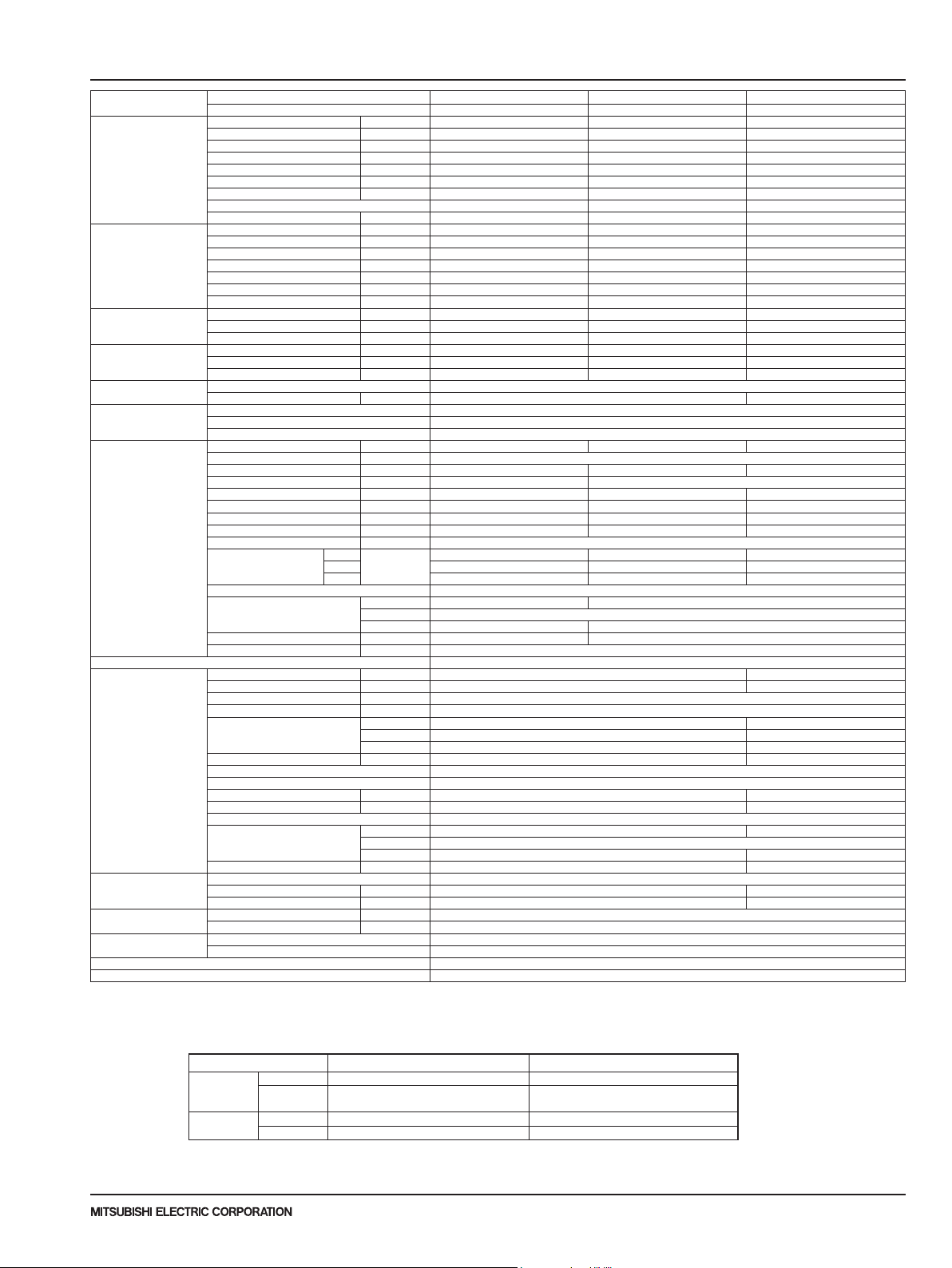
SPECIFICATIONS
2
Model name Indoor unit PVA-A30AA7 PVA-A36AA7 PVA-A42AA7
Cooling Max. Capacity Btu/h 30,000 36,000 42,000
Heating Max. Capacity Btu/h 34,000 40,000 54,000
Heating at 17°F
(-8.3°C)
Heating at 5°F
(-15°C)
Power supply Phase, Cycle, Voltage 1phase, 60Hz, 208/230V
Voltage Indoor - Outdoor S1-S2 AC208/230V
Indoor unit MCA A 4.13 5.50 5.63
Remote Controller Attached in indoor unit
Outdoor unit MCA A 28 37
Refrigerant Type R410A
Refrigerant pipe
size
Refrigerant pipe
length
Refrigerant Piping Not Supplied
Connection Method Flared
Outdoor unit PUZ-HA30NHA5 PUZ-HA36NHA5 PUZ-HA42NKA
Rated Capacity Btu/h 28,500 33,000 42,000
Min. Capacity Btu/h 18,000 18,000 19,000
Total Input W 2,280 2,640 4,270
EER Btu/h/W 12.5 12.5 9.8
SEER Btu/h/W 17.0 17.8 15.3
Moisture Removal Pints/h 8.0 7.9 9.0
SHF 0.70 0.74 0.76
*1 Power factor % 92.6 87.6 88.4
Rated Capacity Btu/h 32,000 38,000 48,000
Min. Capacity Btu/h 18,000 18,000 18,000
Total Input W 2,590 3,040 4,010
COP W/W 3.62 3.66 3.50
HSPF Btu/h/W 9.7/7.5 11.0/9.0 11.0/9.2
*1 Power factor % 93.8 88.7 88.1
Max. Capacity Btu/h 32,000 38,000 48,000
Total Input W 4,930 5,400 6,700
*2 COP W/W 1.90 2.06 2.09
Max. Capacity Btu/h 32,000 38,000 48,000
Total Input W 5,320 6,100 7,360
*3 COP W/W 1.76 1.82 1.91
Breaker size A 30 40
Indoor - Outdoor S2-S3 DC24V
Indoor - Remote Controller DC12V
MOCP A 15
Fan motor F.L.A. 3.3 4.4 4.5
Fan motor output W 244 430
Air ow DRY(Lo-Mid-Hi) CMM 17.3-21.1-24.8 22.3-27.1-31.9 29.4-35.7-42.0
Air ow WET(Lo-Mid-Hi) CMM
Air ow DRY(Lo-Mid-Hi) CFM 613-744-875 788-956-1,125 1,040-1,262-1,485
Air ow WET(Lo-Mid-Hi) CFM
External pressure in.WG [Pa] <75>-125-<200>
Sound level
(Lo-Mid-Hi)
External nish Galvanized steel cabinet-Powder coated Slate Gray
Dimension Unit W: mm [inch] 534[21] 635[25]
Weight Unit kg[lbs] 64 [141] 78 [172]
Field drain pipe size O.D. mm[inch] 19.05 [3/4] FPT
MOCP A 40 44
Fan motor F.L.A. 0.4 + 0.4
Fan motor output W 86 + 86
Compressor Type ANB33FJEMT ANB42FJTMT
Air ow CMM [CFM] 100 [3,530] 94 [3,320]
Refrigerant Control Electronic Expansion Valve
Defrost Method Reverse cycle
Sound level at cooling dB(A) 52 49
Sound level at heating dB(A) 53 51
External nish Munsell 3Y 7.8/1.1
Dimension Unit W: mm [inch] 950 [37-3/8] 1,050 [41-6/16]
Weight Unit kg[lbs] 120 [265] 130 [287]
Charge kg [lbs,oz] 5.5 [12lbs 2oz] 6.0 [13lbs 4oz]
Oil L [oz] 1.4(FV50S) [45] 1.7(FVC68D) [54]
Gas side O.D. mm [inch] 15.88 [5/8]
Liquid side O.D. mm [inch] 9.52 [3/8]
Height difference IU-OU Max. 30m [Max.100ft]
Length Max. 75m [Max.245ft]
75Pa
125Pa 32-36-40 32-36-40 36-40-44
200Pa 35-39-43 37-42-45 39-43-47
dB(A)
D: mm [inch] 548[21-5/8]
H: mm [inch] 1,378 [54-1/4] 1,511 [59-1/2]
R.L.A. 18.0 19.0
L.R.A. 27.5 28.0
D: mm [inch] 300+30 [13 + 1-3/16]
H: mm [inch] 1,350 [53-1/8] 1,338 [52-11/16]
30-34-38 30-34-38 34-38-42
NOTES : *1.Rating conditions (cooling)-Indoor : D.B. 26.7°C(80°F), W.B. 19.4°C(67°F) Outdoor : D.B. 35°C(95°F), W.B. 23.9°C(75°F)
(heating)-Indoor : D.B. 21.1°C(70°F), W.B. 15.6°C(60°F) Outdoor : D.B. 8.3°C(47°F), W.B. 6.1°C(43°F)
*2.Conditions (heating)-Indoor : D.B. 21.1°C(70°F), W.B. 15.6°C(60°F) Outdoor : D.B. -8.3°C(17°F), W.B. -9.4°C(15°F)
*3.Conditions (heating)-Indoor : D.B. 21.1°C(70°F), W.B. 15.6°C(60°F) Outdoor : D.B. -15°C(5°F), W.B. -15°C(5°F)
Operating range
Cooling
Heating
Maximum
Minimum
Maximum
Minimum
Indoor intake air temperature
D.B. 32°C(90°F), W.B. 23°C(73°F)
D.B. 19°C(66°F), W.B. 15°C(59°F)
D.B. 28°C(83°F)
D.B. 10°C(50°F)
Outdoor intake air temperature
D.B. 46°C(115°F)
D.B. -5°C(23°F)
D.B. -18°C(0°F)*
D.B. 21.1°C(70°F), W.B. 15°C(59°F)
D.B. -25°C(-13°F), W.B. -25°C(-13°F)
* In case that the wind baffle is installed. (In case that the wind baffle is not installed, the minimum temperature will be -5°C(23°F)DB.)
Due to continuing improvement, above specication may be subject to change without notice.
P-Series (March 2017)
© 2017 Mitsubishi Electric US, Inc.
19
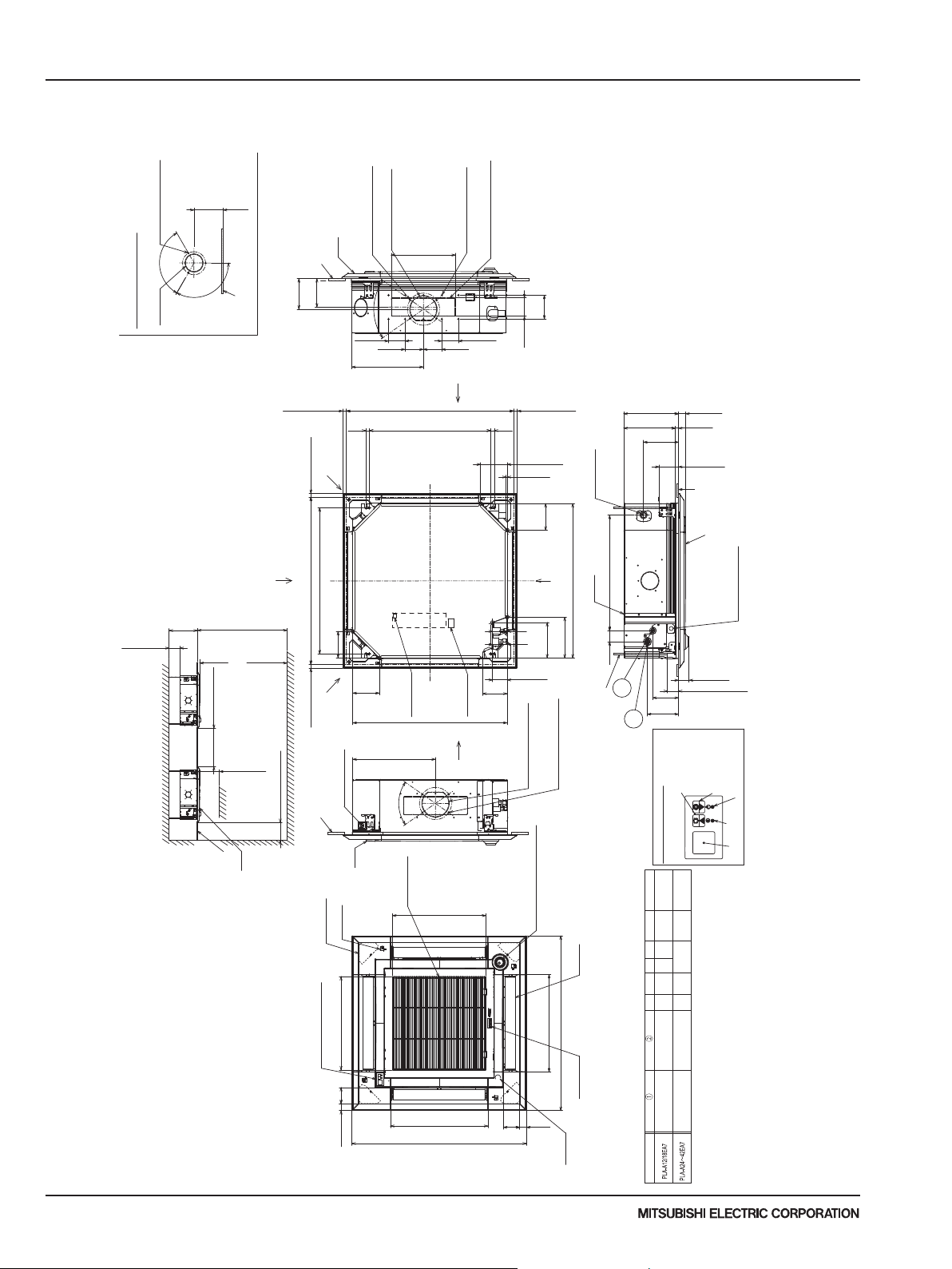
3 OUTLINES AND DIMENSIONS
PLA-A.EA7*
12/18/24/30/36/42
1-15/16 TO 2-3/4
NOTE1.CHOOSE THE GRILLE AMONG THE DEDICATED GRILLES.
2.REINFORCE THE SUSPENSION BOLT FOR EARTHQUAKE-RESISTANCE AS NEEDED.
3.FOR THE SUSPENSION BOLT, USE M10 OR W3/8.
(PROCURED AT THE LOCAL SITE.)
4.FOR DRAIN PIPE, USE VP-25(O.D.
DRAIN PUMP INCLUSION.
RAISE IS MAX 33-7/16''(850mm) FROM THE CEILING.
5.ELECTRICAL BOX MAY BE REMOVED FOR THE SERVICE PURPOSE.
MAKE SURE TO SLACK THE ELECTRICAL WIRE LITTLE BIT FOR
CONTROL/POWER WIRES CONNECTION.
6.THE HEIGHT OF THE INDOOR UNIT IS ABLE TO BE ADJUSTED
WITH THE GRILLE ATTACHED.
7.REQUIRES "E" OR MORE SPACE BETWEEN TRANSOM AND CEILING FOR THE INSTALLATION.
8.WHEN INSTALLING THE BRANCH DUCTS, BE SURE TO INSULATE ADEQUATELY.
OTHERWISE CONDENSATION AND DRIPPING MAY OCCUR.
(IT BECOMES THE CAUSE OF DROPLET OR DROPLET DRIPPING.)
9.AS FOR NECESSARY INSTALLATION/SERVICE SPACE, PLEASE REFER TO THE
RIGHT AT FIGURE.
10.FOR THE INSTALLATION OF THE OPTIONAL HIGH EFFICIENCY FILTER OR
MULTI-FUNCTIONAL CASEMENT,REFER TO SPECIAL DRAWING.
INDOOR UNIT
Unit: inch (mm)
PLA-A12EA7 PLA-A18EA7 PLA-A24EA7 PLA-A30EA7 PLA-A36EA7 PLA-A42EA7
(158)
6-1/4
SELF-TAP 4 SCREWS:3 PLACES
{4-15/16({125) BURRING HOLE PITCH
120°
{3-15/16({100)
CUTOUT HOLE
DETAILS OF FRESH AIR INTAKE HOLE
AND CEILING SLAB
BETWEEN THE TOP OF UNIT
1/4 OR MORE
(7mm)
INDOOR UNIT
INDOOR UNIT
120°
CEILING
SPACE IN THE
E
WALL
32) PVC TUBE).
{
n1-1/4''(
CEILING
F
OR MORE
FROM FLOOR
70-7/8(1800mm) OR MORE
118-1/8(3000mm)
BETWEEN INDOOR UNIT
(1000mm)
OBSTACLE
GRILLE
CEILING
(167)
BRANCH DUCT HOLE
CEILING HEIGHT
FLOOR
39-3/8 OR MORE
59-1/16(1500mm) OR MORE
CEILING
(155)
6-1/8
6-9/16
13/16 TO 1-3/4
(20-45)
(20-45)
INTAKE HOLE
FRESH AIR
13/16 TO 1-3/4
(CEILING HOLE)
31-5/16 (795)
(SUSPENSION BOLT PITCH)
33-7/8 TO 35-13/16(860-910)
(145)
5-11/16
(20-45)
WIRE ENTRY
REMOTE CONTROLLER
13/16 TO 1-3/4
CEILING
CORNER POCKET
OPTIONAL PART:SIGNAL RECEIVER
(89)
GRILLE
REMOTE CONTROLLER
VANE MOTOR
20(508)
3-1/2
1-7/16(37)
Due to continuing improvement, above specication may be subject to change without notice.
P-Series (March 2017)
20
{6-7/8({175) BURRING HOLE PITCH
SELF-TAP 4 SCREWS:4 PLACES
(CONNECTING TO BRANCH DUCT)
70°
3-9/16
(90)
13/16
(20)
5-11/16
(145)
WIRE ENTRY
GRILLE
(AIR INTAKE HOLE)
{5-7/8({150) CUTOUT HOLE
(CONNECTING TO BRANCH DUCT)
3-15/16
(100)
15-3/8(390)
0
TERMINAL BLOCK
CONTROLLER
REMOTE
17-11/16(450)
70°
AIR INTAKE GRILLE
+1-9/16
0
+40
13-3/4
(350)
26
(660 )
33-1/16(840)
(CEILING HOLE)
INDOOR UNIT/
20(508)
SELF-TAP 4 SCREWS:14 PLACES
(CONNECTING TO BRANCH DUCT)
(CONNECTING TO BRANCH DUCT)
13-3/4×3-15/16(350×100) CUTOUT HOLE
3-9/16
(90)
3-15/16
(100)
BRANCH DUCT
HOLE
33-7/8 TO 35-13/16(860-910)
(SUSPENSION BOLT PITCH)
TERMINAL BLOCK
OUTDOOR UNIT
CONNECTING
BRANCH DUCT HOLE
(AIR INTAKE HOLE)
(AIR OUTLET HOLE)
20-7/8(530)
37-3/8(950)
5-1/4
(133)
(100)
13/16
(20)
(89)
(130)
5-1/8
3-15/16
1/4(6)
(145)
5-11/16
C
(222)
D
(193)
7-5/8
3-1/8(79.5)
{5-7/8({150) CUTOUT HOLE
(CONNECTING TO BRANCH DUCT)
{6-7/8({175) BURRING HOLE PITCH
EXCEPT DRAIN PIPE CORNER
SOME GRILLES DO NOT HAVE THIS PART.
*CAN INSTALL TO THE CORNER
I-SEE SENSOR CORNER PANEL
(AIR OUTLET HOLE)
20-7/8(530)
3-1/2
1-7/16
(37)
13/16 TO 1-3/4
(20-45)
5-11/16(145)
VP-25 CONNECTION
DRAIN PIPE
24-3/4(628)
33-1/16(840)
MAIN UNIT
BRANCH DUCT HOLE
8-3/4
(60)
2-3/8
SUSPENSION BOLT
M10 OR W3/8
SELF-TAP 4 SCREWS:4 PLACES
(CONNECTING TO BRANCH DUCT)
(NEED TO FUNCTION SETTING BY
REMOTE CONTROLLER)
AUTO VANE
37-3/8(950)
COMPANY NAME
DRAIN HOLE
(CONNECTED THE ATTACED
DRAIN SOCKET)
1
B
A
7-1/2
(190)
2
(170)
DETAILS OF SIGNAL RECEVER
FE
OR LESS
137-13/16(3500)
OR MORE
10-7/16(265)
D
3(76.5)
C
3(76)
B
(258)
10-3/16
A
9-1/2
(241)
12.7
{
REFRIGERANT PIPE
FLARED CONNECTION 1/2F
REFRIGERANT PIPEΦ6.35
FLARED CONNECTION 1/4F
:
MODELS
1-9/16 (40)
0
11/16
+3/16
0
(17 )
+5
4-1/8 (105)
CEILING
GRILLE
CONNECTING WIRE,
INDOOR UNIT/OUTDOOR UNIT
POWER SUPPLY WIRE ENTRY
THE BOTTOM OF
I-SEE SENSOR
2-5/16 (58)
SUSPENSION BOLT
5-1/2
(140)
6-11/16
SWITCH<UP>
SWITCH <COOLING>AND
EMERGENCY OPERATION
EMERGENCY UP/DOWN
OR LESS
177-3/16(4500)
OR MORE
12(305)
3-1/8
(79.5)
(298)
11-3/4
(281)
11-1/16
15.88
{
REFRIGERANT PIPE
FLARED CONNECTION 5/8F
REFRIGERANT PIPEΦ9.52
FLARED CONNECTION 3/8F
(50-70)
SWITCH<DOWN>
SWITCH <HEATING>AND
EMERGENCY OPERATION
EMERGENCY UP/DOWN
LOWER EDGE
DEFROST/STAND BY LAMP
LAMP
OPERATION
RECEIVER
© 2017 Mitsubishi Electric US, Inc.
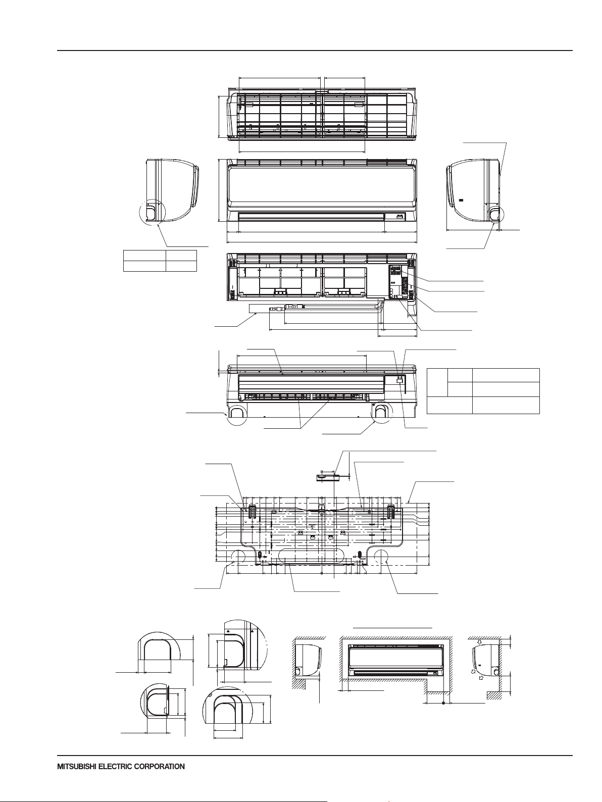
250mm,9-13/16inch or greater with
optional drain pump installation.
OUTLINES AND DIMENSIONS
3
PKA-A12HA7 PKA-A18HA7 Unit: inch (mm)
7-3/4(197)
11-5/8(295)
D
Sleeve
(purchased locally)
[2-1/2~[3-1/8
([65~[80)
Left side
Knock out hole
for left piping
Through hole
[2-1/2~[3-1/8
([65~[80)
Knock out hole
for lower piping
2-1/8
(55)
Drain hose
5/16(8)
15-3/16(387)
23-9/16(599)
7-1/2(192)
Top side
Front side
Mount board
Right side
A
3/16(5)9-13/16(249)
[
6.35)
1/4F (
1/2F ([12.7)
[
5/8 ([16) O.D
Effective length: 15-3/4 (400)
Vane(auto)
27-1/16(688)
35-3/8(898)
Front side(Grille open)
17-15/16(457)Gas pipe
21-3/16(539)Liquid pipe
Under side
24-1/16(612)
Operation lamp
6-1/16(155)
6-5/8(169)
6-3/16(158)
7-3/16(184)
Knock out hole
for right piping
Terminal block for indoor/outdoor
connecting line
Terminal block for power supply (option)
Terminal block for
MA-remote controller
Emergency operation switch
(cooling/heating)
DEFROST/STAND BY lamp
Liquid pipe
Refrigerant
Piping
Gas pipe
Drain hose
Louver(manual)
C
Knock out hole
for lower piping
Receiver
B
4-[5/16([9)
Bolt hole
[
3/16([5.1)
77Tapping
screw hole
0
5/8(16)
1-1/16(28.5)
1-9/16(41)
3-1/16(78.5)
3-9/16(91)
4-1/16(103.5)
4-9/16(116)
6-1/2(166)
7(178.5)
8(203.5)
9-1/8(232.5)
9-15/16(253.5)
Wall hole for
left rear piping
Knock out hole for piping
2-11/16(69)
1-11/16(43)
2-3/16(56)
3/16(6)
1-11/16(43)
2-3/16(56)7/16(12.5)
A
C
1-3/4(46)
Due to continuing improvement, above specication may be subject to change without notice.
2-3/16(56)
3/16(6)
1-3/4(46)
2-5/16(60)
14-5/8(372.3)
14(356.3)
12-7/8(327.5)
11-7/16(291.5)
15-1/2(394)
17-5/8(449)
1-11/16(43)
1-11/16(43)
B
10-3/8(265)
7-13/16(200)
8-13/16(225)
8-3/8(213)
9-5/16(238)
6-13/16(174)
10-15/16(278.3)
D
2-5/16(59)
0
4-7/8(125)
2-3/4(70)
0
9/16(15)
0
Knock out hole for
left rear piping
2-3/4×12-3/16(70×310)
Min.1/4(7)
Center measurement hole [3/32([2.5)
Mount board
2-1/4(58)
5/32(3.8)
8-13/16(225)
2-3/4(70)
4-1/2(115)
7-13/16(200)
4-7/8(125)
5-1/2(140)
6-9/16(167)
7-1/16(180.3)
7-9/16(193.5)
9/16(15)
Required space(Indoor unit)
Min.1-31/32(50)
10-3/8(265)
9-5/16(238)
P-Series (March 2017)
© 2017 Mitsubishi Electric US, Inc.
14(356.3)
12-7/8(237.5)
11-7/16(291.5)
Wall hole for
right rear piping
11-1/16(281)
Indoor unit outline
14-5/8(372.3)
17-5/8(449)
(mm)
Min.8-5/8
(220)
13/16(21.8)
0
3/4(20)
1-1/4(32.7)
2-1/16(53.5)
2-9/16(66)
5(128.5)
6(153.5)
9-1/16(231.5)
10-3/4(273.2)
Air inlet
Air inlet
Air outlet
Min.5-7/8(150)
Min.1-31/32(50)
Min.9-13/16(250)
21
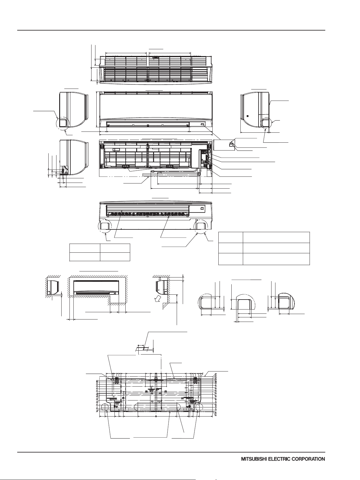
16-15/16(430.5)
8-17/32(216.5)
17-11/16(449.2)
3 OUTLINES AND DIMENSIONS
PKA-A24KA7 PKA-A30KA7 PKA-A36KA7 Unit: inch (mm)
Top side
Front side
17(431.7)16-11/16(423.7)
Right side
Mount board
C
Knockout hole
for left piping
2-9/16(65.2)
5-17/32(140.3)
7/16(11)
Left side
14-3/8(365)
1-1/4(32)
23/32(18)
2-3/32(53)
A
1-3/16(30)
1-3/8(35)
2-19/32(66)
Sleeve
(purchased locally)
Min.9/32(7)
Through hole
[2-15/16
([75)
[2-15/16~[3-5/32
([75~[80)
Required space(Indoor unit)
Min.8-21/32(220)
Min.2-1/16(52.3)
Filter hook
Drain hose
Vane(auto)
Min.3-31/32(100.5)
33-21/32(855)2-29/32(74)
Front side(Grille open)
3
Air inlet
Air outlet
46-1/16(1170)
17-15/32(444)Gas pipe
18-31/32(482)Liquid pipe
Under side
Louver(manual)
Knockout hole
for lower piping
Center measurement hole
[3/32([2.5)
9-1/2(241)
2
1
Min.1-7/8(48)
Min.9-27/32(250)
Operation lamp
DEFROST/STAND BY lamp
Terminal block for Outdoor unit
Terminal block for power supply (option)
Terminal block for
MA-remote controller
Emergency operation switch
(cooling/heating)
4-27/32(123)
6-1/16(154)
5-9/32(134)
Piping connection
1 Liquid pipe
BB
2 Gas pipe
3 Drain hose
Knockout hole for piping
C
2-5/8(67)
3-1/32(77)
2-9/16(65)
5/16(7.8)
2-9/16(65)
11-5/8(295)
Receiver
3/16(5)
Knockout hole
for right piping
Refrigerant pipe: 3/8 O.D([9.52)
Flared connection: 3/8F
Refrigerant pipe: 5/8 O.D([15.88)
Flared connection: 5/8F
5/8([16) O.D
Effective length: 23-1/32 (585)
B
13/32(10.7)
3-1/32(77)
3-7/16(87)
3-1/32(77)
5/16(7.8)
2-5/8(67)
A
2-9/16(65)
2-1/8(54)
0
1/8(3)
4-[11/32([9) Bolt hole
Mount board
75-[3/16([5.1)
Tapping
screw hole
5/8(15.5)
31/32(25)
1-31/32(50)
2-15/16(75)
3-15/16(100)
4-19/32(117)
4-29/32(125)
5-19/32(142)
7-9/16(192)
9-17/32(242)
11(279.5)
11-1/2(292)
0
20-3/8(517.4)
23-1/32(585)
20-7/8(530.5)
17-9/32(439)
17-7/8(454)
16-3/32(408.5)
Wall hole for
left rear piping
15-1/8(384)
14-11/32(364)
15-1/8(384)
13-11/32(339)
12-3/8(314)
0
4-11/32(110)
2-3/8(60)
13/32(10)
0
7-7/16(189)
Knockout hole for
rear piping
2-15/16×18-29/32(75×480)
13/32(10)
2-3/8(60)
4-11/32(110)
R1-15/32(R37.5)
Wall hole for
right rear piping
14-11/32(364)
12-3/8(314)
13-11/32(339)
17-7/8(454)
15-1/8(384.5)
16-3/32(408.5)
17-9/32(439)
15-1/8(384)
13-3/4(349.2)
Indoor unit outline
18-5/16(465.5)
Due to continuing improvement, above specication may be subject to change without notice.
P-Series (March 2017)
22
2-1/8(54)
1-1/4(32)
31/32(25)
1/2(12.5)
0
1/2(12.5)
1-15/32(37.5)
2-15/32(62.5)
3-7/16(87.5)
4-1/8(104.5)
5-3/32(129.5)
6-9/16(167)
8-17/32(217)
9-1/32(229.5)
10-13/32(264)
11-1/2(292)
12-5/32(308.5)
12-1/4(311)
23-1/32(585)
© 2017 Mitsubishi Electric US, Inc.
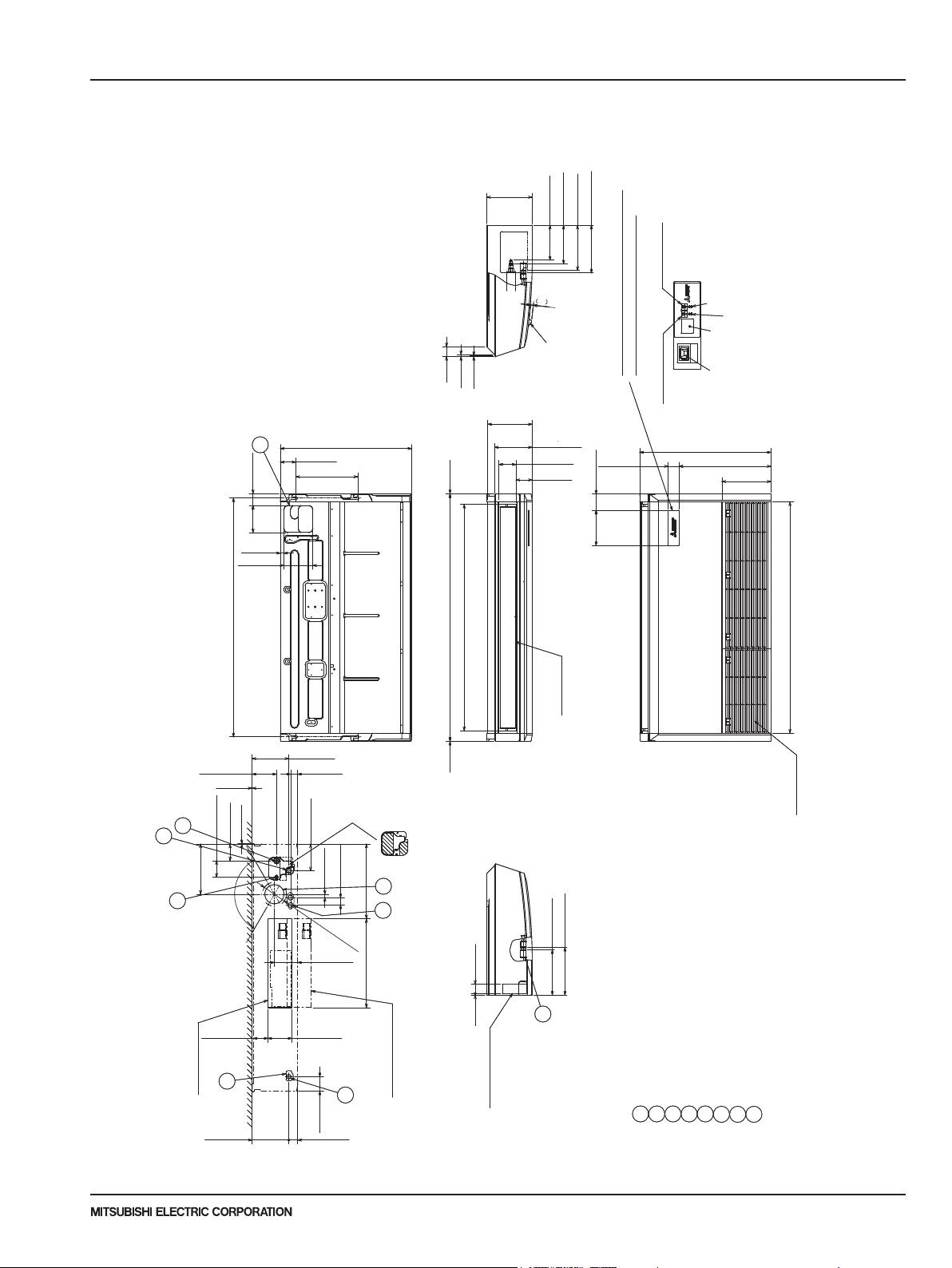
2-15/16(75)
When electrical box
remove the shaded portions from the independent piece.
position.(The heat exchanger might be clogged because of dust)
Knockout hole for upper drain pipe arrangement
Knockout hole for fresh air intake Φ3-15/16(Φ100)
Knockout hole for wiring arrangement Φ7/8(Φ22)
Accessory...Drain socket (1(26mm) I.D.)
Drainage pipe connection(1(26mm)I.D.)
Drainage pipe connection(for the left arrangement)
Knockout hole for left drain-piping arrangement
Refrigerant-pipe connection(gas pipe side/flared connection)
Refrigerant-pipe connection(liquid pipe side/flared connection)
OUTLINES AND DIMENSIONS
3
PCA-A24KA7 PCA-A30KA7 Unit: inch (mm)
Drainage
liquid Φ3/8(Φ9.52)
gas Φ5/8(Φ15.88)
When drain socket
is installed
9-5/16(236)
7-7/8(200)
9-3/16(233)
9-11/16(246)
7-1/16(180)
Emergency operation
switch <Heating>
DEFROST/STAND BY lamp
Operation lamp
Receiver
In case of wireless remote controller
and i-see Sensor(Optional Parts)
Emergency operation
switch <Cooling>
2-1/4(57)
i-see sensor
NOTES.
1.Use M10 or W3/8 screw for anchor bolt.
2.Please be sure when installing the drain pump (option parts),
refrigerant pipe will be only upward.
26-3/4(680)
18-3/4(476)
10(254)
6
2-7/16(62)
3-1/8(80)
12-5/8(320)
26-3/4(680)
2(51)
3/8(10)
3/16(5)
14
9/16
In case of wireless
remote controller
and i-see sensor
9-1/16(230)
7-11/16(195)
3-7/16(88)
3-5/16(84)
(Optional Parts)
3-3/8(85)
5-1/2(140)
11/16(18)
5-7/8(150)
48-11/16(1237) (Suspension bolt pitch)
46-3/16(1173)
7-3/16(182)
47-3/16(1198)
Air outlet
4-15/16(126)
1/16(1)
7-1/12(190)
1-7/16(37)
1/16(2) 1/16(2)50-3/8(1280)
Air intake
4
3-3/8(85)
10-1/4(260)
1/16(2)
3-3/8(86)
120°
Ceiling
3(76)
5-7/16(138)
11/16(18)
1-1/2(38)
Φ4-15/16(Φ125)
4-3/4(121)
4-7/8(124)
15-1/4(387)
7
7
8
8
18-1/8(461)
In case of the rear pipe arrangement, make sure to
1-7/8(48)5/16(8)
Then put the independent piece back in initial
When drain socket
2
Drainage
is installed
9-11/16(246)
9-3/16(233)
1
5
[FRONT VIEW]
3
Electrical box
7-1/2(190)
Due to continuing improvement, above specication may be subject to change without notice.
© 2017 Mitsubishi Electric US, Inc.
2
1-13/16(46)
is pulled down
Electrical box
P-Series (March 2017)
3
214
5
8
7
6
23
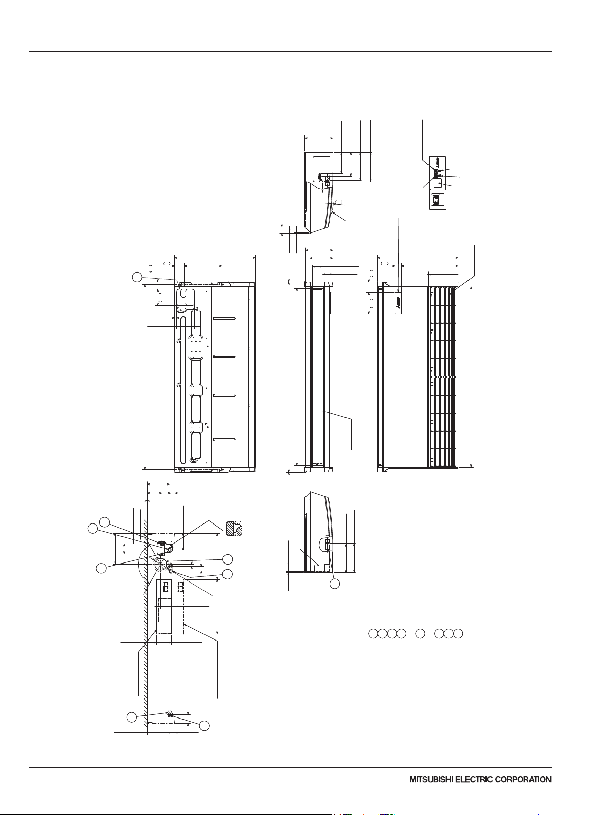
In case of the rear pipe arrangement, make sure to
remove the shaded portions from the independent piece.
Then put the independent piece back in initial
position.(The heat exchanger might be clogged because of dust)
When electrical box
Knockout hole for upper drain pipe arrangement
Knockout hole for fresh air intake Φ3-15/16(Φ100)
Knockout hole for wiring arrangement Φ7/8(Φ22)
Drainage pipe connection(for the left arrangement)
Knockout hole for left drain-piping arrangement
3 OUTLINES AND DIMENSIONS
PCA-A36KA7 PCA-A42KA7 Unit: inch (mm)
Drainage
When drain socket
is installed
gas Φ5/8(Φ15.88)
liquid Φ3/8(Φ9.52)
9-5/16(236)
9-3/16(233)
7-7/8(200)
7-1/16(180)
9-11/16(246)
14
9/16
In case of wireless
remote controller
and i-see sensor
2(51)
3/8(10)
80
3-1/8
62
2-7/165-1/2
6
26-3/4(680)
12-5/8(320)
3/16(5)
1/16(2)
9-1/16(230)
(Optional Parts)
7-11/16(195)
3-7/16(88)
3-5/16(84)
85
Emergency operation
switch <Heating>
DEFROST/STAND BY lamp
Operation lamp
Receiver
In case of wireless remote controller
and i-see sensor(Optional Parts)
Emergency operation
switch <Cooling>
57
2-1/4
26-3/4(680)
18-3/4(476)
10(254)
Air intake
140
11/16(18)
5-7/8(150)
61-5/16(1557) (Suspension bolt pitch)
NOTES.
1.Use M10 or W3/8 screw for anchor bolt.
2.Please be sure when installing the drain pump (option parts),
refrigerant pipe will be only upward.
4-15/16(126)
1/16(1)
4
3-3/8(85)
10-1/4(260)
1/16(2)
3-3/8(86)
1
1
5
120°
7-1/2(190)
5-7/16(138)
11/16(18)
1-7/16(37)
1-1/2(38)
Φ4-15/16(Φ125)
4-3/4(121)
15-1/4(387)
8
18-1/8(461)
7
Ceiling
3(76)
4-7/8(124)
[FRONT VIEW]
58-3/4(1493)
1/16(2) 63(1600)
Electrical box
1-7/8(48)5/16(8)
Air outlet
Drainage
When drain socket
is installed
9-11/16(246)
9-3/16(233)
2
182
7-3/16 3-3/8
59-3/4(1518)
Drainage pipe connection(1(26mm)I.D.)
Refrigerant-pipe connection
(gas pipe side/flared connection)
Refrigerant-pipe connection
(liquid pipe side/flared connection)
5
4
3
2
11
Accessory...Drain socket (1(26mm)I.D.)
8
7
6
Electrical box
2-15/16(75)
2-15/16(75)
is pulled down
3
7-1/2(190)
2
1-13/16(46)
Due to continuing improvement, above specication may be subject to change without notice.
P-Series (March 2017)
24
© 2017 Mitsubishi Electric US, Inc.
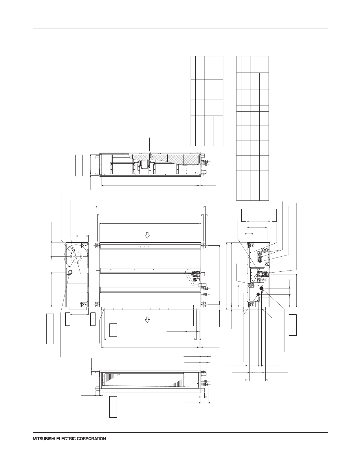
100(3-15/16)
OUTLINES AND DIMENSIONS
3
PEAD-A12AA7 PEAD-A18AA7 PEAD-A24AA7
PEAD-A30AA7 PEAD-A36AA7 PEAD-A42AA7
Unit: mm (inch)
(field supply).
at the bottom.
AA7 models,which have 2 fans. PEAD-A12·
18AA7 models have 1 fan.
filter (supplied with the unit), then
install the filter (field supply) at the
suction side.
2.Keep the service space for maintenance
3.This drawing is for PEAD-A24·30·36·42
4.If the inlet duct is used,remove the air
Note 1.Use an M10 screw for the suspension bolt
Inlet air
side view
18(3/4) 210(8-5/16)
(5-3/8)
135
3-ø2.9(1/8) mount hole
Note 4
Fresh air intake ø100(3-15/16)
knock out hole
120°
taking fresh air with a fresh air intake.
5.Heat air to 0˚C (32˚F) or higher when
Air filter
2Liquid pipe1Gas pipe
Unit:mm(in.)
J
Model
G
C
B(Suspension bolt pitch)23(15/16)
A
Air
inlet
(3/8)
(1/4)
ø9.52
ø6.35
(5/8)
(1/2)
ø12.7
ø15.88
66
62
(2-5/8)
(2-1/2)
PEAD-A24,30AA7
PEAD-A12,18AA7
PEAD-A36,42AA7
21(7/8)
H
Unit:mm(in.)
G
Model AEDCBF
Drain pump
78
72
(2-7/8)
(3-1/8)
8581000
1058
13581300
(53-1/2)
(41-11/16)
1000
(51-3/16)
9
11
14
860 900 954 800
Top
1360
10601100 1154
1500
1200
(47-1/4) (41-3/4)(39-3/8)
1454
(57-1/4) (59-1/16) (53-9/16)
(45-7/16)
1400
(55-1/8)
(43-5/16)
(35-7/16) (37-9/16)(39-3/8) (33-7/8)(31-1/2)(33-13/16)
PEAD-A24,30AA7
PEAD-A12,18AA7
PEAD-A36,42AA7
250(9-7/8)
217(8-9/16)
41(1-5/8)
Bottom
Control box
Terminal block(Transmission)
Terminal block(Power source)
120°
ø125
(4-15/16)
(Suspension bolt pitch)
378(14-15/16) 153(6-1/16)
200(7-7/8)
Bottom
side view
Opposite piping
(Emergency drain)
Drain pipe(O.D ø32(1-1/4))
Top
2XE-ø2.9(1/8)
15(5/8)
40(1-5/8)
Top
view
side view
Outlet air
Air
outlet
10(7/16)
100(3-15/16)
J±3(J±1/8)
40(1-5/8)
H±3(H±1/8)
57(2-1/4) 643(25-3/8)
58(2-5/16)
Due to continuing improvement, above specication may be subject to change without notice.
P-Series (March 2017)
© 2017 Mitsubishi Electric US, Inc.
732(28-7/8)
30(1-3/16) 100(3-15/16)X(E-1)=F
20(13/16) D(Duct)
(Integral lift pump outlet)
(O.Dø32(1-1/4))
Drain pipe
700(27-9/16)
238(9-3/8)
10(7/16)
32(1-5/16)
2Refrigerant piping(liquid)
122(4-13/16)
40(1-5/8)
23(15/16)
2X2-ø2.9(1/8)
(DUCT)
Drain pipe(O.Dø32(1-1/4))(Gravity drain)
(2-11/16)
356(14-1/16)
136 67
(5-3/8)
Piping
side view
1Refrigerant piping (gas)
33(1-5/16)
178(7-1/16)
25

(4-7/16) (4-7/16)
Control box
Access door 2(450×450
(17-3/4X17-3/4)
Access door
of the arrow Y)
of the arrow Y)
• Create access door 1 and 2 (450x450mm each) as shown in Fig.2.
(Access door 2 is not required if enough space is available below the unit for a maintenance worker to work in.
(1) When a space of 300mm or more is available below the unit between the unit and the ceiling. (Fig.1)
and control box in one of the following ways
Secure enough access space to allow for the maintenance, inspection, and replacement of the moto
[Maintenance access space]
• Create access door 4 below the control box and the unit as shown in Fig.5.
Create access door 1 diagonally below the control box and access door
(2) When a space of less than 300mm is available below the unit
(At least 20mm of space should be left below the unit as
Select an installation site for the indoor unit so that it's maintenance access space will not be obstructed by beams or other
3 OUTLINES AND DIMENSIONS
Less than 700(27-9/16)
112112
11(7/16)
K
T
(59-1/16)
S
1000
(39-3/8)
Unit:mm(in.)
1700
(66-15/16)
1200
(47-1/4)
2000
(78-3/4)
1500
(59-1/16)
(Accessory)
Drain hose(I.D ø32(1-1/4))
LX(M-1)=N
L
K
6(1/4)
P-ø2.9 (1/8)
(11-13/16)
Min. 300mm
objects.
(11-13/16)
Less than 300
0
0
)
-10
65
-7/16
(Actual length)
(2-9/16 )
r, fan, drain pump, heat exchanger,
(27-9/16)
700
(2)
50
3 below the unit as shown in Fig.4.
(17-3/4)
(11-13/16)
between the unit and the ceiling.
shown in Fig.3.)
(27-9/16)
700 Min. 300mm
.
450
(17-3/4)
(18-3/4)
475
(450×450)
Access door 1
(17-3/4X17-3/4)
450
Control box
(450×450)
Access door 2
(17-3/4X17-3/4)
(7/16)
indoor unit
Bottom of
Min. 10mm
(3-15/16~7-7/8)
100~200
Q
air
Intake
air
Supply
450R
(17-3/4)
(11-13/16)
Min. 300mm
Maintenance
access space
(17-3/4)
(Viewed from the direction
of the arrow Z)
50~150 450
Fig.2
(2~5-15/16)
(11-13/16)
Min. 300mm
(27-9/16)
(18-3/4)
475
700
(2)
50
Access door 1
450
(17-3/4)
(450×450)
(17-3/4X17-3/4)
Control box
(17-3/4)
450
Control box
R
150~250 1500
250~350
(5-15/16)~(9-7/8)
(9-7/8)~(13-13/16)
Q
900
1100
(43-5/16)
(35-7/16)
P
10
10
NKLM
780
990
4
4
(13) (39)
330
260
49
54
(2-3/16) (10-1/4) (30-3/4)
(1-15/16)
Model
PEAD-A24,30AA7
PEAD-A12,18AA7
Q
Intake
air
indoor unit
Bottom of
air
Supply
T
(3-15/16~7-7/8)
100~200
Q
Intake
air
indoor unit
Bottom of
air
Supply
S
(7/16)
Min. 10mm
(13/16)
Min. 20mm
400~500
(15-3/4)~(19-11/16)
1400
(55-1/8)
12
1280
(50-7/16)
5
320
54
(2-3/16) (12-5/8)
PEAD-A36,48AA7
50
(2)
Maintenance
access space
(30-5/8)
777
Access door 4
Access door 3
(2)
50
Maintenance
access space
(30-5/8)
777
Fig.5
Fig.4
(Viewed from the direction
(Viewed from the direction
Intake airSupply air
Ceiling
Z
Fig.1
)
Ceiling beam
or
•
Control box
Intake air
Supply air
Due to continuing improvement, above specication may be subject to change without notice.
P-Series (March 2017)
26
Ceiling
Y
Ceiling beam
Fig.3
3
© 2017 Mitsubishi Electric US, Inc.
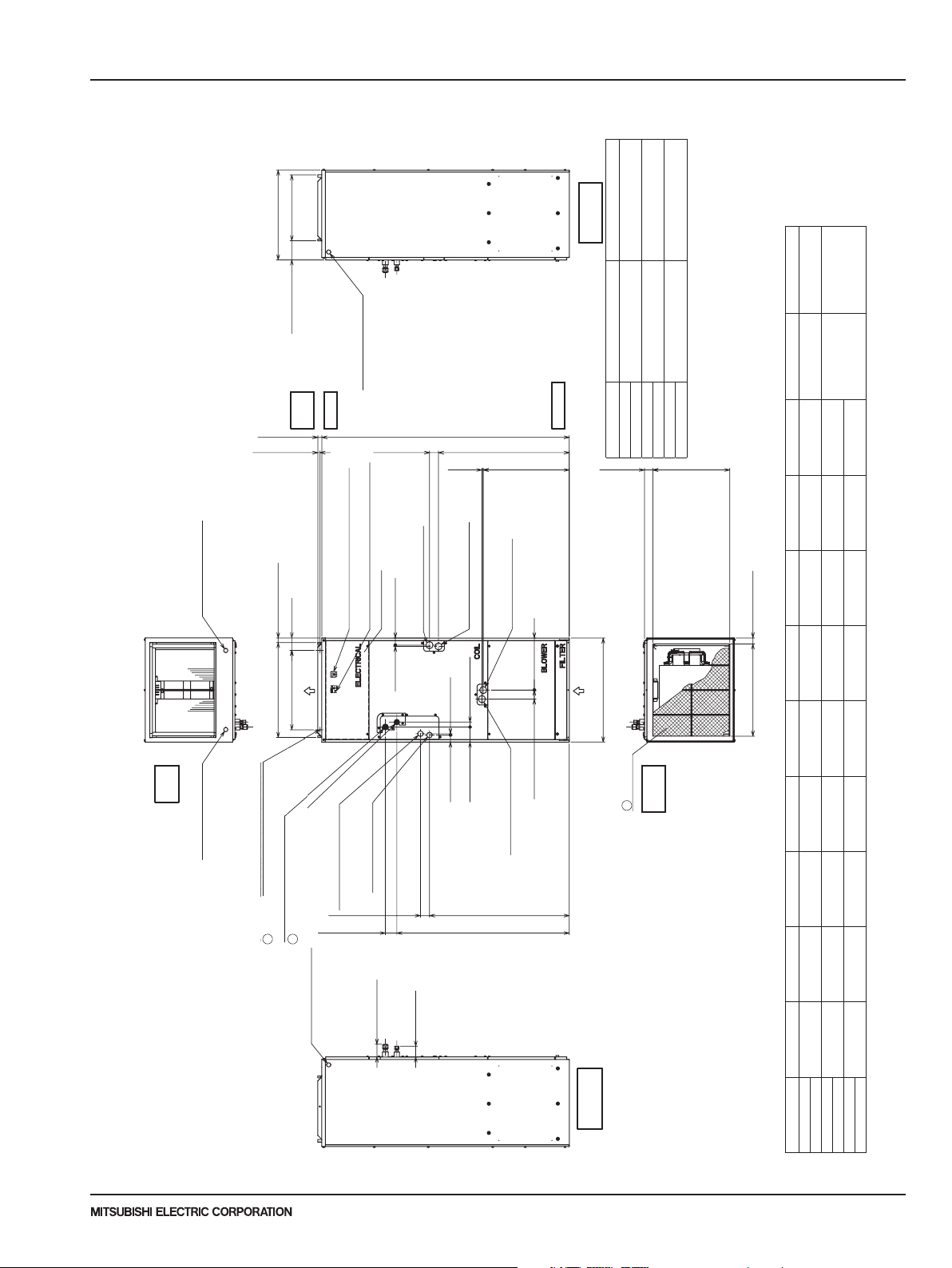
(18-3/16)
(20X24X1) (22-13/16X15-7/8)
(31-3/16)
(18-13/16) (15-1/8) (10-1/2) (54-1/4) (29-1/16) (37-9/16)
(25) (22-13/16) (19-1/8) (12-1/2) (31-7/16) (41-1/2) (33-5/8) (22-3/16)
(21)
(20X20X1) (18-13/16X15-7/8)
Model ABCDEFGHJ
Gas pipe Liquid pipe
PVA-A30AA4
477 382.6 266.5 1378 737 953.5
PVA-A36AA4
635 579 484.6 317.5
1511
(59-1/2)
798.5 1053 853.5 563
PVA-A42AA4
PVA-A30AA4
PVA-A36AA4
PVA-A42AA4
(5/8) (3/8)
461
534
508X609.6X25.4
579X402
470(18-9/16)
792
Ø15.88 Ø9.52
1
2
(18-3/16)
(20X24X1) (22-13/16X15-7/8)
(31-3/16)
(20X20X1) (18-13/16X15-7/8)
Gas pipe Liquid pipe
1511
(59-1/2)
798.5 1053 853.5 563
Model
Nominal Filter si z e
Duct Connection
P VA-A30AA4
P VA-A36AA4
P VA-A42AA4
(5/8) (3/8)
461
508X609.6X25.4
508X508X25.4
579X402
477X402
J
36.8(1-1/2)
43(1-3/4) 8(3/8)
92(3-5/8) 30(1-3/16)
43(1-3/4)
8(3/8)
55(2-3/16)
548(21-5/8)
117.4 (4-5/8)
402(15-7/8)
B(Duct)
28.8(1-3/16)
76(3)
C
A
D
525.5(20-3/4)50.8(2)470(18-9/16)
H
55(2-3/16)
G
70(2-13/16)
8(3/8)
F
55(2-3/16)
E
24(15/16)
13.2(9/16)
Control b ox
Air filter
Air outlet
Air inlet
(Duct)
Ref rigerant piping
Ref rigerant piping
are connection(liquid)
P rimary d rain pipe
(G ravity drain)
ø19.05(3/4) 3/4"FPT
Seconda ry drain pipe
(Emergency d raining)
ø19.05(3/4) 3/4"FPT
P rimary d rain pipe
(G ravity drain)
ø19.05(3/4) 3/4"FPT
(Ho rizontal left)
(Ho rizontal Right)
Seconda ry drain pipe
(Emergency d raining)
ø19.05(3/4) 3/4"FPT
P rimary d rain pipe
(G ravity drain)
ø19.05(3/4) 3/4"FPT
Seconda ry drain pipe
(Emergency d raining)
ø19.05(3/4) 3/4"FPT
Terminal block
(Indoor / Outdoor unit connection)
Terminal block
(Remote controller t ransmission)
for elect ric heat installation
ø26 Kno ckout Hole
(Remote controller t ransmission)
792
Ø15.88 Ø9.52
Top
Front
Bottom
Bottom
view
view
Right side
view
1
3
3
2
2
(18-3/16)
(20X24X1) (22-13/16X15-7/8)
(31-3/16)
(20X20X1) (18-13/16X15-7/8)
Gas pipe Liquid pipe
1511
(59-1/2)
798.5 1053 853.5 563
Model
Nominal Filter si z e
Duct Connection
P VA-A30AA4
P VA-A36AA4
P VA-A42AA4
(5/8) (3/8)
461
508X609.6X25.4
508X508X25.4
579X402
477X402
J
36.8(1-1/2)
43(1-3/4) 8(3/8)
92(3-5/8) 30(1-3/16)
43(1-3/4)
8(3/8)
55(2-3/16)
117.4 (4-5/8)
402(15-7/8)
76(3)
C
A
D
525.5(20-3/4)50.8(2)470(18-9/16)
H
55(2-3/16)
G
70(2-13/16)
8(3/8)
F
55(2-3/16)
E
24(15/16)
13.2(9/16)
Control b ox
Air filter
Air outlet
Air inlet
(Duct)
Ref rigerant piping
are connection(liquid)
P rimary d rain pipe
(G ravity drain)
ø19.05(3/4) 3/4"FPT
Seconda ry drain pipe
(Emergency d raining)
ø19.05(3/4) 3/4"FPT
P rimary d rain pipe
(G ravity drain)
ø19.05(3/4) 3/4"FPT
(Ho rizontal left)
(Ho rizontal Right)
Seconda ry drain pipe
(Emergency d raining)
ø19.05(3/4) 3/4"FPT
P rimary d rain pipe
(G ravity drain)
ø19.05(3/4) 3/4"FPT
Seconda ry drain pipe
(Emergency d raining)
ø19.05(3/4) 3/4"FPT
Terminal block
(Indoor / Outdoor unit connection)
Terminal block
(Remote controller t ransmission)
ø26 Kno ckout Hole
(Remote controller t ransmission)
792
Ø15.88 Ø9.52
Top
Front
Bottom
Bottom
view
view
Right side
view
1
3
3
2
OUTLINES AND DIMENSIONS
3
PVA-A12AA7 PVA-A18AA7 PVA-A24AA7
PVA-A30AA7 PVA-A36AA7 PVA-A42AA7
(Duct)
Unit:mm(in.)
402(15-7/8)
548(21-5/8)
376 x 402
view
Duct Connection
Right side
477 x 402
579 x 402
(14-13/16 x 15-7/8)
(18-13/16 x 15-7/8)
(22-13/16 x 15-7/8)
477X402
Duct Connection
Unit: mm (in.)
Liquid Pipe
Unit: mm (inch)
Note 1.Keep the service space for maintenance at the front.
ø26 Knockout Hole
Top
view
117.4 (4-5/8)
Top
view
Front
24(15/16)
13.2(9/16)
(Remote controller transmission)
28.8(1-3/16)
76(3)
Terminal block
Terminal block
(Remote controller transmission)
C
B(Duct)
Air outlet
ø26 Knockout Hole
(Remote controller transmission)
E
55(2-3/16)
8(3/8)
43(1-3/4)
Control box
Primary drain pipe
(Gravity drain)
(Indoor / Outdoor unit connection)
ø19.05(3/4) 3/4"FPT
8(3/8)
Primary drain pipe
(Horizontal Right)
Secondary drain pipe
(Emergency draining)
ø19.05(3/4) 3/4"FPT
43(1-3/4) 8(3/8)
92(3-5/8) 30(1-3/16)
Bottom
F
525.5(20-3/4)50.8(2)
D
(Gravity drain)
ø19.05(3/4) 3/4"FPT
55(2-3/16)
Nominal Filter Size
Model
Air inlet
A
(20 x 16 x 1)
(20 x 20 x 1)
PVA-A12AA7 508 x 406.4 x 25.4
PVA-A18AA7
PVA-A24AA7 508 x 508 x 25.4
PVA-A30AA7
PVA-A36AA7 508 x 609.6 x 25.4
Air filter
view
3
Bottom
(20 x 24 x 1)
PVA-A42AA7
Nominal Filter size
3
Model
508X508X25.4
Gas Pipe
36.8(1-1/2)
J
Φ 15.88 (5/8) Φ 9.52 (3/8)
Secondary drain pipe
(Emergency draining)
H
G
ø19.05(3/4) 3/4"FPT
P-Series (March 2017)
ø26 Knockout Hole
Primary drain pipe
(Gravity drain)
ø19.05(3/4) 3/4"FPT
(Horizontal left)
ø19.05(3/4) 3/4"FPT
55(2-3/16)
70(2-13/16)
77.8(3-1/8)
66(2-5/8)
2-ø4.6 Burring Holes
for electric heat installation
(Indoor / Outdoor unit connection)
Secondary drain pipe
(Emergency draining)
are connection(gas)
brazing connection(gas)
Refrigerant piping
brazing connection(liquid)
Refrigerant piping
1
2
1
2
unit connection)
ø26 Knockout Hole
(Indoor /Outdoor
Due to continuing improvement, above specication may be subject to change without notice.
© 2017 Mitsubishi Electric US, Inc.
Left side
432 (17) 376 (14-13/16) 281 (11-1/8) 224 (8-7/8) 1275 (50-1/4) 680 (26-13/16) 823 (32-7/16) 735.5 (29) 360 (14-3/16) Φ 12.7 (1/2) Φ 6.35 (1/4)
534 (21) 477 (18-13/16) 382.6 (15-1/8) 266.5 (10-1/2) 1378 (54-1/4) 737 (29-1/16) 953.5 (37-9/16) 792 (31-3/16) 461 (18-3/16)
635 (25) 579 (22-13/16) 484.6 (19-1/8) 317.5 (12-1/2) 1511 (59-1/2) 798.5 (31-7/16) 1053 (41-1/2) 853.5 (33-5/8) 563 (22-3/16)
view
Model A B C D E F G H J
PVA-A12AA7
PVA-A18AA7
PVA-A24AA7
PVA-A30AA7
PVA-A36AA7
PVA-A42AA7
27
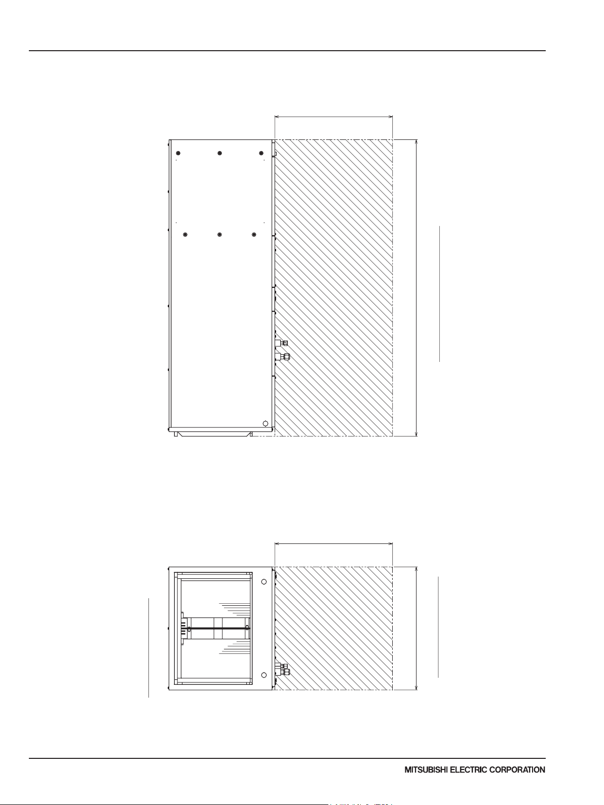
ance Area
ertical Installation
3 OUTLINES AND DIMENSIONS
PVA-A12AA7 PVA-A18AA7 PVA-A24AA7
PVA-A30AA7 PVA-A36AA7 PVA-A42AA7
Service space
Unit:mm(in.)
Unit: mm (inch)
609.6(24)
Length of Unit
609.6(24)
Horizontal Installation
Width of Unit
Clear
Due to continuing improvement, above specication may be subject to change without notice.
P-Series (March 2017)
28
V
© 2017 Mitsubishi Electric US, Inc.
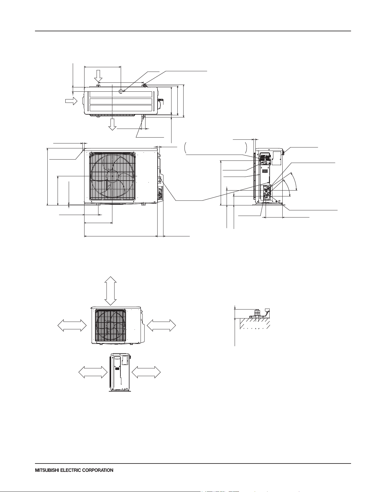
OUTLINES AND DIMENSIONS
3
OUTDOOR UNIT Unit: mm (inch)
PUZ-A12/18NKA7 PUZ-A12/18NKA7-BS PUY-A12/18NKA7 PUY-A12/18NKA7-BS
48<1-29/32>
Air intake
22.3 <29/32>
Handle for moving
630 <24-13/16>
8.5<11/32>
320<12-5/8>
154.5 <6-3/32>
404.5<15-15/16>
Air intake
Installation bolt pitch
Air discharge
310 <12-7/32>
drain hole
ø 42
500<19-11/16>
40 <1-19/32>
2-10×21
(Foundation Bolt M10
<W 3/8>)
809 <31-7/8> 62 <2-15/32>
2-U Shaped notched holes
(Foundation Bolt M10<W 3/8>)
300<11-13/16>
oval hole
32.5<1-9/32>
22 <7/8>
330<13>
360<14-3/16>
Terminal connection
...
Left
Power supply wiring
...
Right
2-
ø
22.2<7/8>
1/2 conduit hole
23.2<15/16>
Indoor/Outdoor wiring
Earth terminal
Service panel
492<19-3/8>
Service port
164.5<6-1/2>
99.5<3-15/16>
Service panel
for charge plug
Connection for
liquid pipe
35
43
°
°
Connection for
FLARE ø12.7 (1/2F)
gas pipe
185.5 <7-5/16>
FLARE ø6.35 (1/4F)
Free space around the outdoor unit
(basic example)
100mm<3-15/16> or more as long as
no obstacle is placed on the
rear and right-and-left sides
of the unit
Basically open
Min.100mm
<3-15/16>
Min.350mm
<13-25/32>
Min.100mm
<3-15/16>
Min.500mm
<19-11/16>
2 sides should be open in
the right, left and rear side.
FOUNDATION BOLTS
Please secure the unit firmly
with 4 foundation (M10<W3/8>) bolts.
(Bolts, washers and nut must
be purchased locally).
<Foundation bolt height>
FOUNDATION
Max.
18 mm<23/32>
PIPING-WIRING DIRECTION
Piping and wiring connection can
be made from the rear direction only.
Due to continuing improvement, above specication may be subject to change without notice.
P-Series (March 2017)
© 2017 Mitsubishi Electric US, Inc.
29
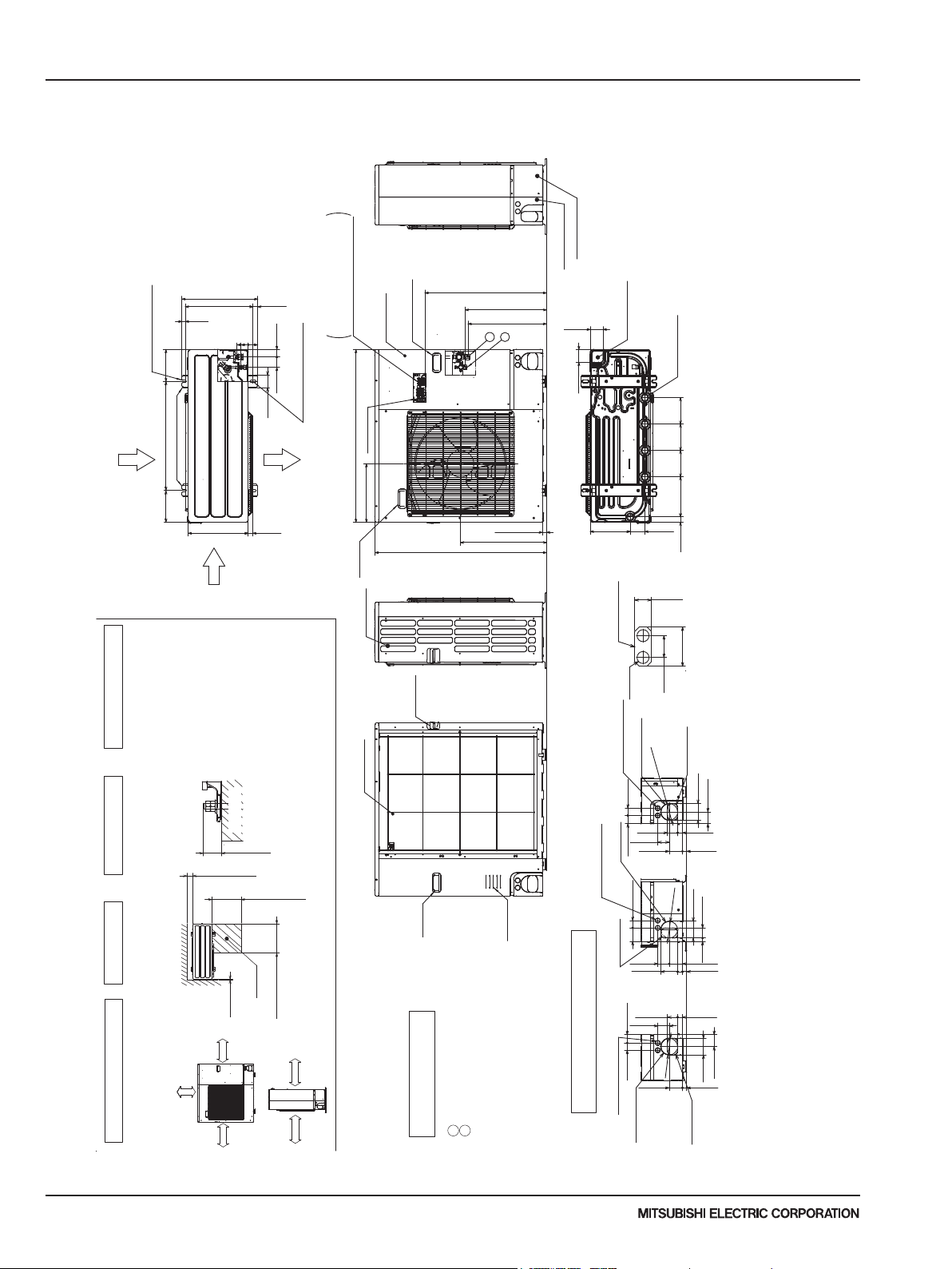
Min. 500mm
Min. 10mm
Refrigerant GAS pipe connection (FLARE)
Refrigerant LIQUID pipe connection (FLARE)
Indication of S
Example of Notes
<29/32>
<1-1/16>
Power supply wiring hole
Front trunking hole
(knockout)
Front piping hole
(knockout)
<29/32>
<1-1/16>
<29/32>
<2-7/18>
Piping knockout Hole Details
1 FREE S
ACE (Around the unit)
The diagram below shows a
basic example.
Explantion of particular details are
given in the installation manuals etc.
3 OUTLINES AND DIMENSIONS
PUZ-A24/30NHA7 PUZ-A24/30NHA7-BS Unit: mm (inch)
PUY-A24/30NHA7 PUY-A24/30NHA7-BS
Rear piping cover
Front piping cover
1
943 <37-1/8>
669<26-11/32>
*1 447<17-5/8>
*1 431<16-31/32>
<2-13/16>
71
Bottom piping hole
2
71<2-13/16>
23 <29/32>
473 <18-5/8>
(knockout)
(5- ø33<1-5/16>)
Drain hole
145
<5-23/32>
145
<5-23/32>
145
<5-23/32>
220
<8-21/32>
81<3-3/16> 219 <8-5/8>
30 <1-3/16>
31<1-7/32>
2-U Shaped notched holes
(Foundfation Bolt M10<W3/8>)
175<6-7/8>
Rear Air Intake
Installation Feet
175 <6-7/8> 600 <23-5/8>
Side Air Intake
417 <1-1/32>
19<3/4>
61<2-13/32>
0
40<19/32>
28<1-3/32> 370<14-9/16>
53<2-3/32>
41 <1-5/8>
57<2-1/4>
2-12×36 oval holes
(Foundation Bolt M10<W3/8>)
70 <2-3/4>
Indoor/Outdoor wiring
...
Power supply wiring
...
Terminal Connections
Left
Reight
Handle for moving
Service panel
Earth terminal
950 <37-13/32>
Air Discharge
330 <13>
25 <31/32>
322<12-11/16>
for moving
Handle
can be made from 4 directions:
Piping and wiring connections
FRONT,Right,Rear and Below.
4 PIPING-WIRING DIRECTIONS
FOUNDATION
10 <13>
<3/8>
<3/8>
100 <3-15/16>
Min.
Service
space
30 <1-3/16>
Max.
Min.
500 <19-11/16>
3 FOUNDATION BOLTS2 SERVICE SPACE
Please secure the unit firmly
Dimensions of space needed
<Foundation bolt height>
with 4 foundation (M10<W3/8>) bolts.
(Bolts and washers must be
purchased locally.)
for service access are
shown in the below diagram.
Min.
Min. 10mm
P
FREE
<3-15/16>
Min.100mm
<19-11/16>
500 <19-11/16>
Min.
Side Air Intake
Rear Air Intake
for moving
Handle
Handle for
moving
ø 9.52(3/8F)
ø15.88(5/8F)
TOP VALVE connection location.
...
...
...
2
1
*1
Air Intake
1/2 Conduit attachment
When installing the conduit,
Set the attachment to the
inner side of each panel.
Power supply wiring hole
Right trunking hole
Power supply wiring hole
(2- ø27knockout)
Right piping hole
40<1-9/16>
2-ø22.2<7/8>
Rear trunking hole
(knockout)
92 <3-5/8>
(2- ø 27<1-1/16>knockout)
ø
55 <2-3/16>
63<2-1/2>
73<2-7/18>
45<1-25/32> 40<1-9/16>
(knockout)
<3-5/8>
40<1-9/16>75 <2-31/32>
92
ø
63 <2-1/2>
(knockout)
92 <3-5/8>
55<2-3/16>
63<2-1/2>
45<1-25/32>
92
ø
<3-5/8>
40<1-9/16>
73<2-7/8>
(2-ø27knockout)
74<2-19/32>
Rear piping hole
(knockout)
92<3-5/18>
65 <2-9/16>
27
23
92 <3-5/8>
19<3/4> 55 <2-3/16>
73
23
<1-1/16>
27
27
65<2-9/16>
92<3-5/8>
23
Due to continuing improvement, above specication may be subject to change without notice.
30
P-Series (March 2017)
© 2017 Mitsubishi Electric US, Inc.
 Loading...