

Mitsubishi PEA-A12AA4, PEA-A18AA4 Installation Manual
Air-Conditioners
PEA-A12, 18AA4
INSTALLATION MANUAL
For safe and correct use, please read this installation manual thoroughly before installing the air-conditioner
unit.
MANUEL D’INSTALLATION
Veuillez lire le manuel d’installation en entier avant d’installer ce climatiseur pour éviter tout accident et vous
assurer d’une utilisation correcte.
FOR INSTALLER
POUR L’INSTALLATEUR
English
Français
3
3.1
[Fig. 3-1]
[Fig. 3-2]
■ PUY-A·NHA
PUZ-A·NHA
(Unit: mm [in])
450 [17-23/32]
E
(Unit: mm [in])
A Access door
B Electrical parts box
C Air inlet
D Air outlet
E Ceiling surface
F Service space (viewed from the side)
G Service space (viewed from the direction of arrow)
Model
PEA-A12AA4
PEA-A18AA4
A
900 [35-7/16]
1100 [43-5/16]
1 600 mm [23-5/8 in] or more
2 100 mm [3-15/16 in] or more
3 10 mm [13/32 in] or more
4 300 mm [11-13/16 in] or more
B
952 [37-1/2]
1152 [45-3/8]
C
998 [39-5/16]
1198 [47-3/16]
(Unit: mm [in])
D
860 [33-7/8]
1060 [41-3/4]
E
1000 [39-3/8]
1200 [47-1/4]
50 ~ 150 [1-31/32 ~ 5-29/32]
C
4
B
A
C
D
49 [1-15/16] 625 [24-5/8]
2
3
D
B
F
E
23
[29/32]
90
[3-9/16]
B
20 [13/16]
450 [17-23/32]
A
57 [2-1/4]
1
200 [7-7/8]
A
G
777 [30-19/32]
3.3
(1),
1000 [39-3/8]
4
[Fig. 4-1]
100 [3-15/16]
100 [3-15/16]
200 [7-7/8]
350 [13-25/32]
200 [7-7/8]
1000 [39-3/8]
150 [5-29/32]
100 [3-15/16]
500 [19-11/16]
LW
Z
YX
A
500 [19-11/16]
A Center of gravity
350 [13-25/32]
300 [11-13/16]
2
5
[Fig. 5-1] [Fig. 5-2] [Fig. 5-3]
A
C
D
5.25.1
6
[Fig. 6-1]
[Fig. 6-3]
a
a Copper tubes
b Good
B
A Unit body
B Lifting machine
a
90°
c No good
d Tilted
øA
øB
dcbef
e Uneven
f Burred
D
C
E
C Nuts (field supply)
D Washers (accessory)
E M10 hanging bolt (field supply)
A Indoor unit’s bottom surface
6.1
b
a Indoor unit
b Outdoor unit
Model
PEA-A12AA4
PEA-A18AA4
A
12.7 [1/2]
12.7 [1/2]
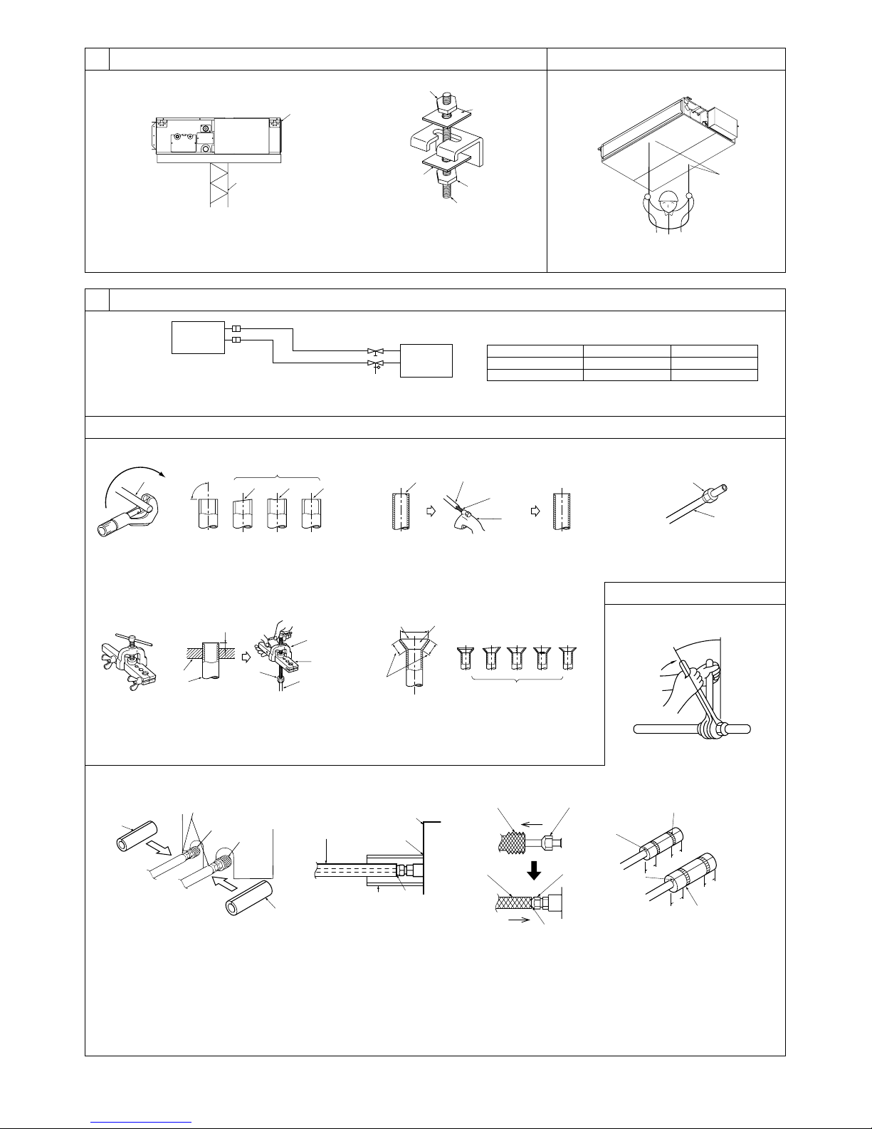
6.2
[Fig. 6-4] [Fig. 6-5]
a
a Burr
b Copper tube/pipe
b
c
d
c Spare reamer
d Pipe cutter
a Flare nut
b Copper tube
A
(Unit: mm [in])
B
6.35 [1/4]
6.35 [1/4]
a
b
[Fig. 6-6]
a
A
e
b
a Flaring tool
b Die
c Copper tube
c
d
d Flare nut
e Yo k e
c
[Fig. 6-9]
B
A
C
D
F
E
G
A Pipe cover (120 mm [3/4 in] small diameter) (accessory)
B Caution:
Pull out the thermal insulation on the refrigerant piping at the
site, insert the flare nut to flare the end, and replace the insulation in its original position.
Take care to ensure that condensation does not form on exposed copper piping.
C Liquid end of refrigerant piping
b
a Smooth all around
b Inside is shining without
any scratches
c Even length all around
E
D Gas end of refrigerant piping
E Site refrigerant piping
F Main body
G Pipe cover (120 mm [3/4 in] large diameter)
(accessory)
H Thermal insulation (field supply)
I Pull
J Flare nut
AG
[Fig. 6-7]
a
c
6.3
b
defg h
i
d Too much
e Tilted
f Scratch on
flared plane
M
H
g Cracked
h Uneven
i Bad examples
J
I
L
F
H
J
L
L
K
K Return to original position
L Ensure that there is no gap here
M Plate on main body
N Tie band (accessory)
O Ensure that there is no gap here. Place join upwards.
[Fig. 6-8]
O
N
20
[13/16]
20
[13/16]
O
20
[13/16]
20
[13/16]
N
3
6.5
[Fig. 6-10]
[Fig.6-11]
Max. 20m [65 ft]
1.5-2 m [5 to 7 ft]
C
A
B
K
L
Max. 300 mm [11-13/16 in]
N
F
Correct piping
Wrong piping
A Insulation (9 mm [3/8 in] or more)
B
B Downward slope (Drain pipes should have an inclination of
J
O
1/100 or more.)
C Support metal
K Air bleeder
L Raised
M Odor trap
Grouped piping
D O. D. ø32 mm [1-1/4 in] PVC TUBE
B
D
E
F
FF
K
D
I
H
J
F
M
(Unit: mm [in])
D
G
[Fig.6-12]
G
E Make it as large as possible. About 10 cm [3-15/16 in].
F Indoor unit
G Make the piping size large for grouped piping.
H Downward slope (Drain pipes should have an inclination of
1/100 or more.)
I O. D. ø38 mm [1-1/2 in] PVC TUBE for grouped piping.
(9 mm [3/8 in] or more insulation)
J Up to 550 mm [21-21/32 in]
N Drain hose (accessory)
O Horizontal or slightly upgradient
I
A
B
F
G
A
35
B
C
25 [1] 25 [1]
[1-13/32]
DE E
H
I
A Indoor unit
B Pipe cover (60 mm [3/8 in]) (accessory)
C Tie band (accessory)
D Visible part
E Insertion margin
F Drain hose (accessory)
G Drain pipe (O.D. ø32 mm [1-1/4 in] PVC TUBE, field supplied)
H Insulating material (field supplied)
I Tie band (accessory)
J Max.180 ± 5 mm [7-3/32 ± 7/32 in]
K To be gap free. The joint section of the insulation material meet must be at the top.
[Fig. 6-13]
B
F
A
E
C
D
[Fig. 6-14]
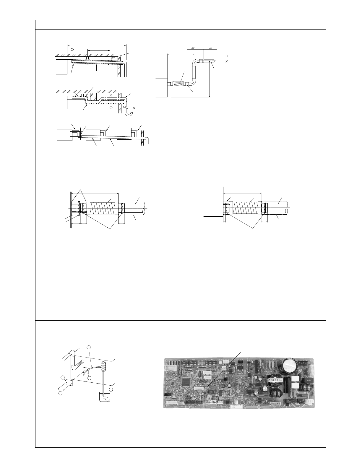
6.6
525
D
E
C
A Indoor unit
B Pipe cover (30 mm [3/16 in]) (accessory)
C Tie band (accessory)
D Band fixing part
E Insertion margin
F Drain hose (accessory)
G Drain pipe (O.D. ø32 PVC TUBE, field supplied)
H Insulating material (field supplied)
I Max.145 ± 5 mm
SWE
H
A Insert pump's end 2 to 4 cm [13/16 to 1-19/32 in].
B Remove the water supply port.
C About 2000 cc
D Water
E Filling port
F Screw
4
<Indoor board>
A
B
C
7
[Fig. 7-1]
F
E
DC
BA
G
A Air inlet
B Air outlet
C Access door
D Ceiling surface
E Canvas duct
F Air filter
G Inlet grille
8
8.1
[Fig. 8-1]
S1
S2
S3
A
CN105
RED
F
21
B
S3
S2S1
G
C
E
For Power supply
D
8.2
[Fig. 8-2-1] [Fig. 8-2-2]
A
A Indoor unit
B Outdoor unit
C Wired remote controller
D Main switch/fuse
E Grounding
F Indoor controller board
G Radio frequency interface for RF thermostat
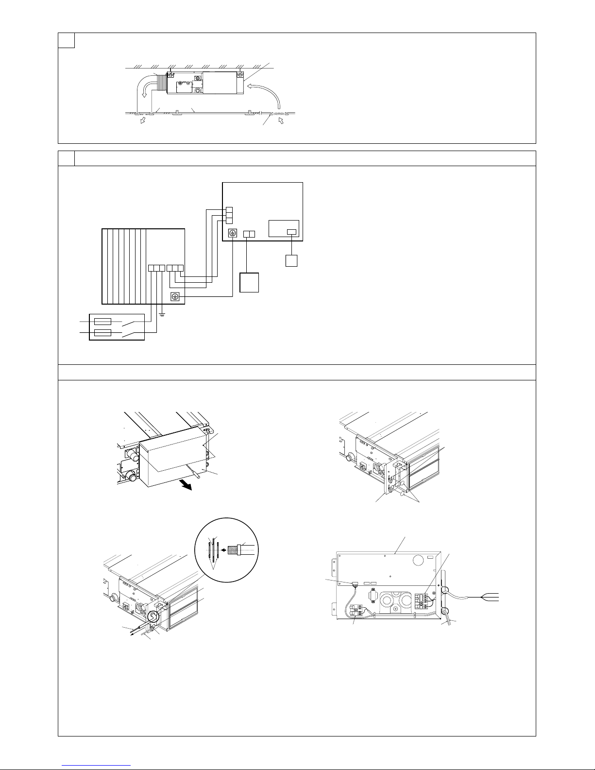
[Fig. 8-2-3] [Fig. 8-2-4]
A
B
G
A Use conduit to keep the weight of the cable and external force from being applied to
the power supply terminal connector.
B Indoor/outdoor unit connecting cable
C Conduit
D Ter minal block box
E Knockout hole (for indoor/outdoor unit connecting cable)
F Washer (accessory)
G Tensile force
H Use ordinary bushing
I Wired remote controller cable or wiring for radio interface
C
I
B
A Screw holding cover (2pcs)
B Cover
D
E
F
A
H
C
E
F
B
A Te r minal block for indoor/outdoor unit connecting
B Te r minal block for wired remote controller
C Indoor/outdoor unit connecting cable
D Wired remote controller cable
E Indoor controller board
F CN105 (RED/5P)
G Wiring for radio interface
A Ter minal block box
B Knockout hole
C Remove
A
D
G
S3
S2
C
S1
5
8
8.2
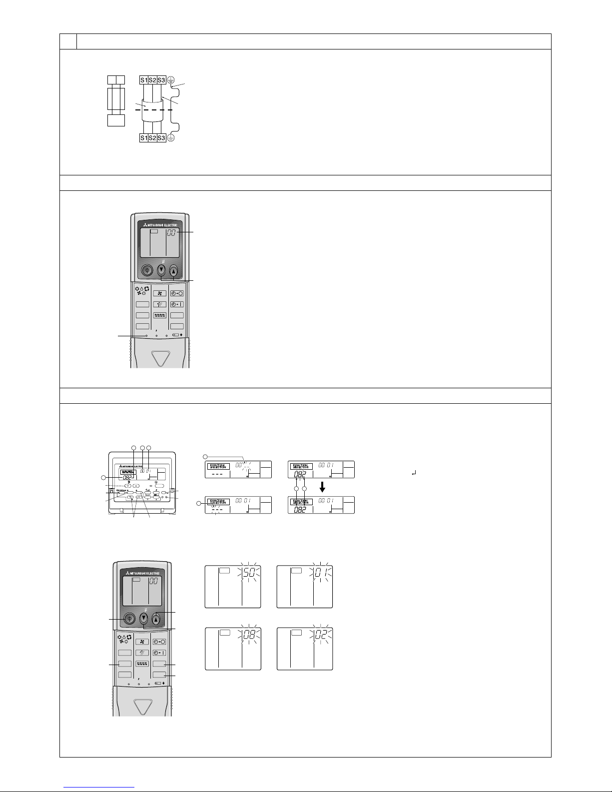
[Fig. 8-3]
5
6
[Fig. 8-4]
2,4
A Indoor terminal block
2
12
1
3
D Outdoor terminal block
CHECK
ON/OFF TEMP
MODE
LOUVER
CHECK
TEST RUN
RESETSET CLOCK
FAN
VANE
B Ground wire (green/yellow)
4
C Indoor/outdoor unit
connecting cable
3-core 1.5 mm
[AWG 16] or more
A
3
AUTO STOP
AUTO START
h
min
A Indoor terminal block
B Ground wire (green/yellow)
C Indoor/outdoor unit connecting cable 3-
core 1.5 mm2 [AWG 16] or more
2
D Outdoor terminal block
1 Indoor/outdoor unit connecting cable 3-
core 1.5 mm2 [AWG 16] or more, in conformity with Design 245 IEC 57.
2 Indoor terminal block
4 Always install an earth wire (1-core 1.5 mm
[AWG 16]) longer than other cables
5 Wired remote controller cable
Wire No × size (mm2) : Cable 2C × 0.3
This wire accessory of remote controller
(wire length : 10m [32 ft], non-polar. Max. 500 m
[1640 ft])
6 Wired remote controller
2
3 Outdoor terminal block
8.3
[Fig. 8-5]
1
F
E
G
[Fig. 8-6]
E
F
213 4
TEMP.
MENU
BACK DAY
MONITOR/SET
PAR-21MAA
CLOCK
CHECK
ON/OFF TEMP
VANE
MODE
LOUVER
CHECK
TEST RUN
RESETSET CLOCK
8.4
1
⁄ Mode number
2
⁄ Setting number
3
4
⁄ Refrigerant address
4
⁄ Unit number
A Filter button (<Enter> button)
ON/OFF
ON/OFF
FILTER
A
CHECK
TEST
OPERATION
CLEAR
B
1 2
B TEST button
C Set Time button
D Timer On/Off button (Set Day button)
E Mode selection button
DC
12
CHECKCHECK
F Set temperature button
G Timer Menu button (Monitor/Set button)
A Hour button
D
AUTO STOP
AUTO START
h
min
C
A
FAN
CHECK CHECK
3
4
B Minute button
C TEMP button
D TEMP button
E ON/OFF button
F CHECK button
B
6
11
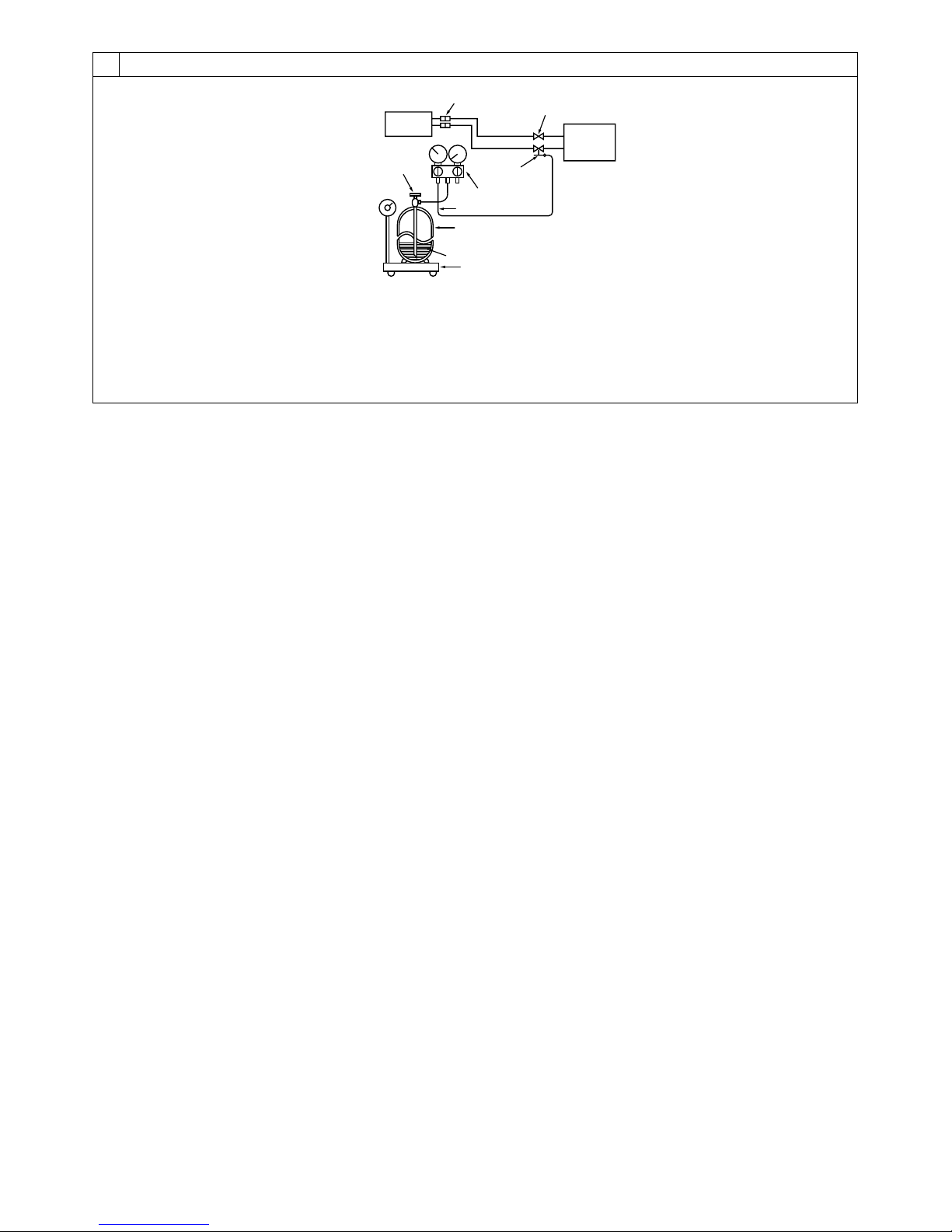
[Fig. 11-1]
11.1
B
A
C
D
G
L
K
H
I
J
E
F
M
A Indoor unit
B Union
C Liquid pipe
D Gas pipe
E Stop valve
F Outdoor unit
G Refrigerant gas cylinder operating valve
H Refrigerant gas cylinder for R410A with
siphon
I Refrigerant (liquid)
J Electronic scale for refrigerant charging
K Charge hose (for R410A)
L Gauge manifold valve (for R410A)
M Service port
7
Contents
1. Safety precautions ................................................................................... 8
2. Selecting the installation location ............................................................. 8
3. Selecting an installation site & Accessories ............................................. 9
4. Fixing hanging bolts ................................................................................. 9
5. Installing the unit ...................................................................................... 9
6. Refrigerant piping work .......................................................................... 10
7. Duct work ............................................................................................... 12
8. Electrical work ........................................................................................ 12
1. Safety precautions
• Please report to or take consent by the supply authority before connection
to the system.
• Be sure to read “The following should always be observed for safety” before
installing the air conditioner.
• Be sure to observe the cautions specified here as they include important
items related to safety.
• The indications and meanings are as follows.
Warning:
Could lead to death, serious injury, etc.
Caution:
Could lead to serious injury in particular environments when operated incorrectly.
• After reading this manual, be sure to keep it together with the instruction
manual in a handy place on the customer’s site.
Warning:
• Do not install it by yourself (customer).
Incomplete installation could cause injury due to fire, electric shock, the unit
falling or leakage of water. Consult the dealer from whom you purchased the
unit or special installer.
• Install the unit securely in a place which can bear the weight of the unit.
When installed in an insufficient strong place, the unit could fall causing injured.
• Use the specified wires to connect the indoor and outdoor units securely and
attach the wires firmly to the terminal board connecting sections so the stress
of the wires is not applied to the sections.
Incomplete connecting and fixing could cause fire.
• Do not use intermediate connection of the power cord or the extension cord
and do not connect many devices to one AC outlet.
It could cause a fire or an electric shock due to defective contact, defective
insulation, exceeding the permissible current, etc.
• Check that the refrigerant gas does not leak after installation has completed.
9. Test run .................................................................................................. 14
10. Easy maintenance function.................................................................... 16
11. Maintenance .......................................................................................... 16
This Installation Manual describes only for the indoor unit.
If the connected outdoor unit is PUY, PUZ series, refer to the Installation Manual
for PUY, PUZ series.
Symbols put on the unit
: Indicates an action that must be avoided.
: Indicates that important instructions must be followed.
: Indicates a part which must be grounded.
: Indicates that caution should be taken with rotating parts.
: Indicates that the main switch must be turned off before servicing.
:Beware of electric shock.
:Beware of hot surface.
Warning:
Carefully read the labels affixed to the main unit.
•Perform the installation securely referring to the installation manual.
Incomplete installation could cause a personal injury due to fire, electric shock,
the unit falling or leakage of water.
•Perform electrical work according to the installation manual and be sure to
use an exclusive circuit.
If the capacity of the power circuit is insufficient or there is incomplete electrical work, it could result in a fire or an electric shock.
• Attach the electrical part cover to the indoor unit and the service panel to the
outdoor unit securely.
If the electrical part cover in the indoor unit and/or the service panel in the
outdoor unit are not attached securely, it could result in a fire or an electric
shock due to dust, water, etc.
• Be sure to use the part provided or specified parts for the installation work.
The use of defective parts could cause an injury or leakage of water due to a
fire, an electric shock, the unit falling, etc.
•Ventilate the room if refrigerant leaks during operation.
If the refrigerant comes in contact with a flame, poisonous gases will be released.
Caution:
•Perform grounding.
Do not connect the ground wire to a gas pipe, water pipe arrester or telephone
ground wire. Defective grounding could cause an electric shock.
• Do not install the unit in a place where an inflammable gas leaks.
If gas leaks and accumulates in the area surrounding the unit, it could cause
an explosion.
• Install a ground leakage breaker depending on the installation place (where it
is humid).
If a ground leakage breaker is not installed, it could cause an electric shock.
2. Selecting the installation location
2.1. Indoor unit
• Where airflow is not blocked.
• Where cool air spreads over the entire room.
• Where it is not exposed to direct sunshine.
• At a distance 1 m [39-3/8 in] or more away from your TV and radio (to prevent
picture from being distorted or noise from being generated).
• In a place as far away as possible from fluorescent and incandescent lights (so the
infrared remote control can operate the air conditioner normally).
2.2. Outdoor unit
• Where it is not exposed to strong wind.
• Where airflow is good and dustless.
• Where it is not exposed to rain and direct sunshine.
• Where neighbours are not annoyed by operation sound or hot air.
• Where rigid wall or support is available to prevent the increase of operation sound
or vibration.
• Where there is no risk of combustible gas leakage.
• When installing the unit at a high level, be sure to fix the unit legs.
• Where it is at least 3 m [10 ft] away from the antenna of TV set or radio. (Otherwise,
images would be disturbed or noise would be generated.)
•Perform the drainage/piping work securely according to the installation
manual.
If there is a defect in the drainage/piping work, water could drop from the unit
and household goods could be wet and damaged.
•Fasten a flare nut with a torque wrench as specified in this manual.
When fastened too tight, a flare nut may broken after a long period and cause
a leakage of refrigerant.
• Where the air filter can be removed and replaced easily.
Warning:
Mount the indoor unit into a ceiling strong enough to withstand the weight of
the unit.
• Install the unit horizontally.
Caution:
Avoid the following places for installation where air conditioner trouble is liable to occur.
• Where there is too much machine oil.
• Salty environment as seaside areas.
• Hot-spring areas.
• Where sulfide gas exists.
• Other special atmospheric areas.
8
3. Selecting an installation site & Accessories
• Select a site with sturdy fixed surface sufficiently durable against the weight of unit.
• Before installing unit, the routing to carry in unit to the installation site should be
determined.
• Select a site where the unit is not affected by entering air.
• Select a site where the flow of supply and return air is not blocked.
• Select a site where refrigerant piping can easily be led to the outside.
• Select a site which allows the supply air to be distributed fully in room.
• Do not install unit at a site with oil splashing or steam in much quantity.
• Do not install unit at a site where combustible gas may generate, flow in, stagnate
or leak.
• Do not install unit at a site where equipment generating high frequency waves (a
high frequency wave welder for example) is provided.
• Do not install unit at a site where fire detector is located at the supply air side. (Fire
detector may operate erroneously due to the heated air supplied during heating
operation.)
• When special chemical product may scatter around such as site chemical plants
and hospitals, full investigation is required before installing unit. (The plastic components may be damaged depending on the chemical product applied.)
• If the unit is run for long hours when the air above the ceiling is at high temperature/
high humidity (due point above 79 °F [26 °C]), due condensation may be produced
in the indoor unit. When operating the units in this condition, add insulation material
(10-20 mm [13/32 to 13/16 in]) to the entire surface of the indoor unit to avoid due
condensation.
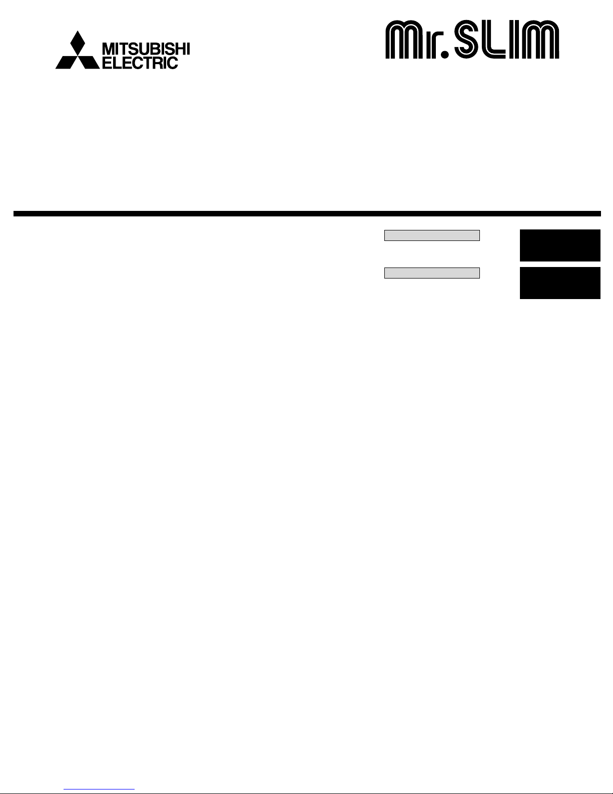
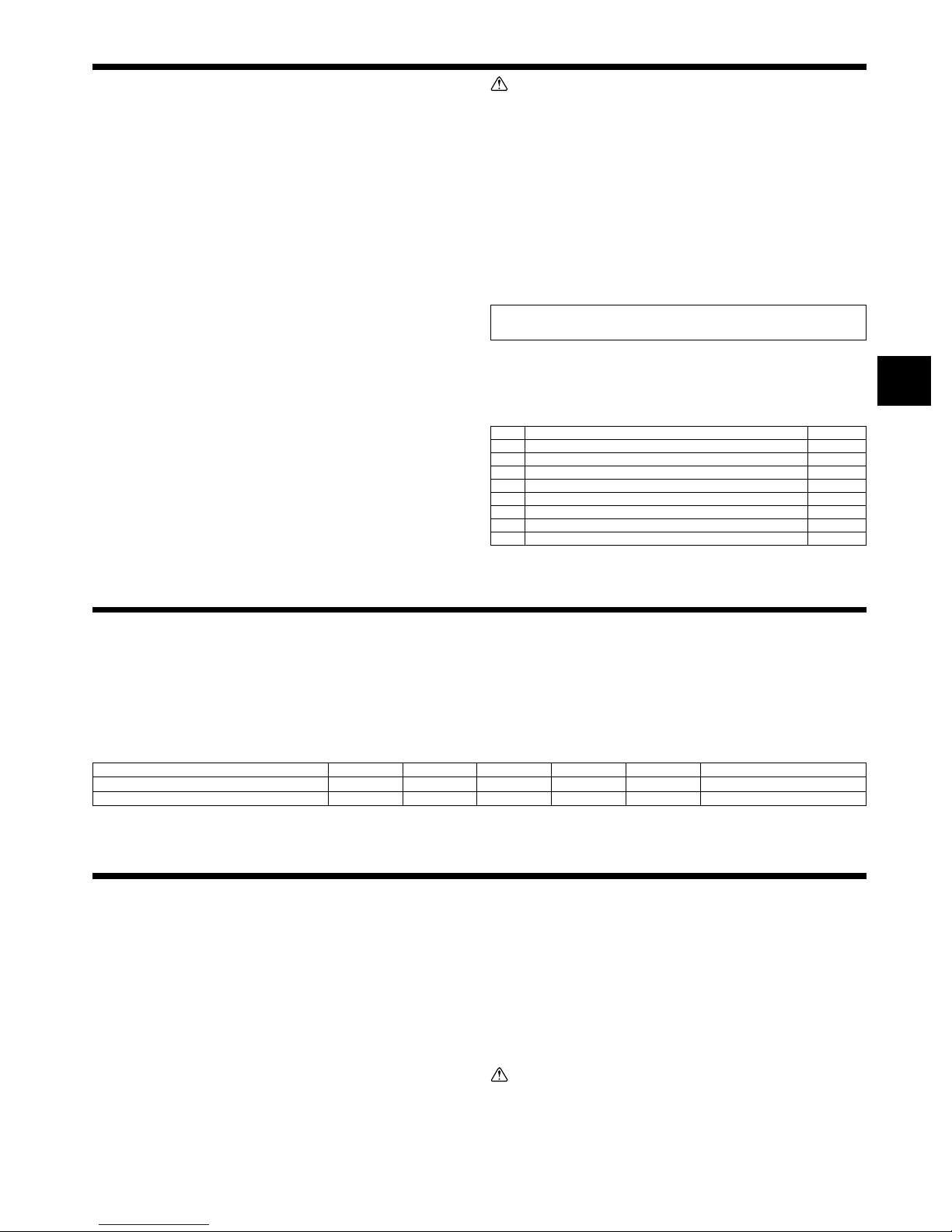
3.1. Install the indoor unit on a ceiling strong enough
to sustain its weight
[Fig. 3-1] (P.2)
A Access door B Electrical parts box
C Air inlet D Air outlet
E Ceiling surface F Service space (viewed from the side)
G Service space (viewed from the direction of arrow)
1 600 mm [23-5/8 in] or more 2 100 mm [3-15/16 in] or more
3 10 mm [13/32 in] or more 4 300 mm [11-13/16 in] or more
Warning:
The unit must be securely installed on a structure that can sustain its weight. If
the unit is mounted on an unstable structure, it may fall down causing injuries.
3.2. Securing installation and service space
• Select the optimum direction of supply airflow according to the configuration of the
room and the installation position.
• As the piping and wiring are connected at the bottom and side surfaces, and the
maintenance is made at the same surfaces, allow a proper space properly. For the
efficient suspension work and safety, provide a space as much as possible.
3.3. Outdoor unit
Ventilation and service space
■ PUY-A·NHA(1), PUZ-A·NHA
[Fig. 3-2] (P.2)
Units should be installed by licensed contractor accordingly to local code requirement.
For outdoor units to be connected, refer to the Installation Manual that comes with
the units.
3.4. Indoor unit accessories
The unit is provided with the following accessories:
No. Name Quantity
1
Pipe cover (for refrigerant piping joint) 120 mm [3/4 in] Small diameter
2
Pipe cover (for refrigerant piping joint) 120 mm [3/4 in] Large diameter
3 Tie band 7
4 Washer (for hanging) 8
5 Drain hose 1
6 Pipe cover (for Drain hose) 60 mm [3/8 in] 1
7 Pipe cover (for Drain hose) 30 mm [3/16 in] 1
8 Washer (for power source wiring) 2
1
1
4. Fixing hanging bolts
4.1. Fixing hanging bolts
[Fig. 4-1] (P.2)
A Center of gravity
(Give site of suspension strong structure.)
Hanging structure
• Ceiling: The ceiling structure varies from building to one another. For detailed information, consult your construction company.
Center of gravity and Product Weight
Model name
PEA-A12AA4
PEA-A18AA4
W (mm [in])
625 [24-5/8]
625 [24-5/8]
L (mm [in])
952 [37-1/2]
1152 [45-3/8]
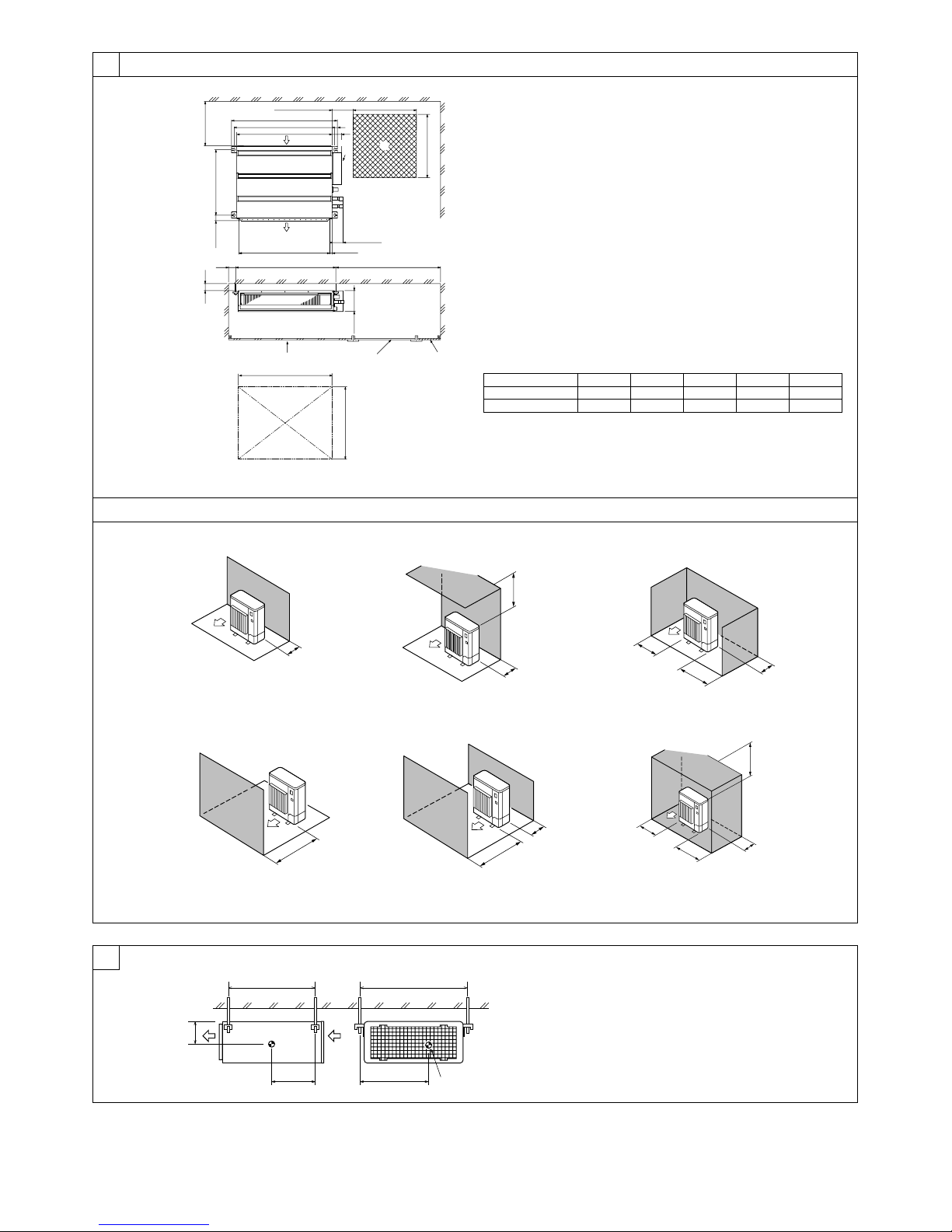
5. Installing the unit
5.1. Hanging the unit body
ss
s Bring the indoor unit to an installation site as it is packed.
ss
ss
s To hang the indoor unit, use a lifting machine to lift and pass through the
ss
hanging bolts.
[Fig. 5-1] (P.3)
A Unit body
B Lifting machine
[Fig. 5-2] (P.3)
C Nuts (field supply)
D Washers (accessory)
E M10 hanging bolt (field supply)
• If necessary, reinforce the hanging bolts with anti-quake supporting members as
countermeasures against earthquakes.
* Use M10 for hanging bolts and anti-quake supporting members (field supply).
1 Reinforcing the ceiling with additional members (edge beam, etc.) must be re-
quired to keep the ceiling at level and to prevent the ceiling from vibrations.
2 Cut and remove the ceiling members.
3 Reinforce the ceiling members, and add other members for fixing the ceiling boards.
X (mm [in])
286 [11-9/32]
285 [11-1/4]
Y (mm [in])
448 [17-21/32]
527 [20-3/4]
Z (mm [in])
104 [4-1/8]
104 [4-1/8]
Product Weight (kg [Ib])
22 [50]
28 [62]
5.2. Confirming the unit’s position and fixing hanging
bolts
ss
s Use the gage supplied with the panel to confirm that the unit body and
ss
hanging bolts are positioned in place. If they are not positioned in place, it
may result in dew drops due to wind leak. Be sure to check the positional
relationship.
ss
s Use a level to check that the surface indicated by
ss
the hanging bolt nuts are tightened to fix the hanging bolts.
ss
s To ensure that drain is discharged, be sure to hang the unit at level using a
ss
level.
[Fig. 5-3] (P.3)
A Indoor unit’s bottom surface
Caution:
Be sure to install the unit body at level.
AA
A is at level. Ensure that
AA
9
 Loading...