

Mitsubishi PLA-A18BA, PLA-A36BA, PLA-A24BA, PLA-A30BA, PLA-A42BA Technical Data Book
...
TECHNICAL DATA BOOK
<Indoor unit>
[Model names]
R410A
PLA-A·BA
PKA-A·HA
PKA-A·HAL
PKA-A·KA
PKA-A·KAL
PCA-A·KA
PEA-A·AA
PEAD-A·AA
<Outdoor unit>
[Model names]
No. DOCS14
No. DOCS15
REVISED EDITION-A
SPLIT-TYPE, HEAT PUMP AIR CONDITIONERS
SPLIT-TYPE, AIR CONDITIONERS
PUZ-A18/24/30/36/42NHA3
PUZ-A18/24/30/36/42NHA3-BS
PUY-A12/18/24/30/36/42NHA3
PUY-A12/18/24/30/36/42NHA3-BS
PUZ-HA30/36NHA2
September 2010
/
INVERTER HYPER HEATING INVERTER
CONTENTS
1. REFERENCE SERVICE MANUAL
.............................................
2
2. SPECIFICATIONS
.......................................................................
3
3. OUTLINES AND DIMENSIONS
................................................
15
4. POSITION OF THE CENTER OF GRAVITY
............................
28
5. WIRING DIAGRAM
...................................................................
30
6. REFRIGERANT SYSTEM DIAGRAM
......................................
41
7. PERFORMANCE CURVES
......................................................
45
8. PERFORMANCE CHART
.........................................................
49
9. CORRECTION FACTORS
........................................................
67
10. AIR FLOW DATA
......................................................................
71
11. NOISE CRITERION CURVES
..................................................
86
12. OPTIONAL PARTS
....................................................
Back cover
* This data book is revised version
of OCS14 and OCS15.
Revision A:
• Cooling performance curve of
the PUZ-A• NHA3(-BS),
PUY-A• NHA3(-BS) is modified.
Please void DOCS14,DOCS15.
2
For information on service, please refer to the service manual as follows.
1-1. INDOOR UNIT
Model name Service Ref.
Service
Manual No.
PLA-A12/18/24/30/36/42BA PLA-A12/18/24/30/36/42BA1
OCH420
OCB420
HWE09050
BWE09180
HWE08070
BWE0811A
PCA-A24/30/36/42KA PCA-A24/30/36/42KA
PEA-A12/18AA PEA-A12/18AA.TH
PEAD-A24/30/36/42AA PEAD-A24/30/36/42AA
PUZ-HA30/36NHA2 PUZ-HA30/36NHA2
OCH455
OCB455
OCH456
OCB456
OCH457
OCB457
PKA-A12/18HA PKA-A12/18HA
PKA-A12/18HAL PKA-A12/18HAL
PKA-A24/30/36KA PKA-A24/30/36KA.TH
PKA-A24/30/36KAL PKA-A24/30/36KAL.TH
1-2. OUTDOOR UNIT
Model name Service Ref.
Service
Manual No.
PUZ-A18/24/30/36/42NHA3
PUZ-A18/24/30/36/42NHA3
OCH458
OCB458
OCH426
OCB426
PUZ-A18/24/30/36/42NHA3-BS
PUZ-A18/24/30/36/42NHA3-BS
PUY-A12/18/24/30/36/42NHA3
PUY-A12/18/24/30/36/42NHA3
PUY-A12/18/24/30/36/42NHA3-BS PUY-A12/18/24/30/36/42NHA3-BS
1
REFERENCE SERVICE MANUAL
3
2
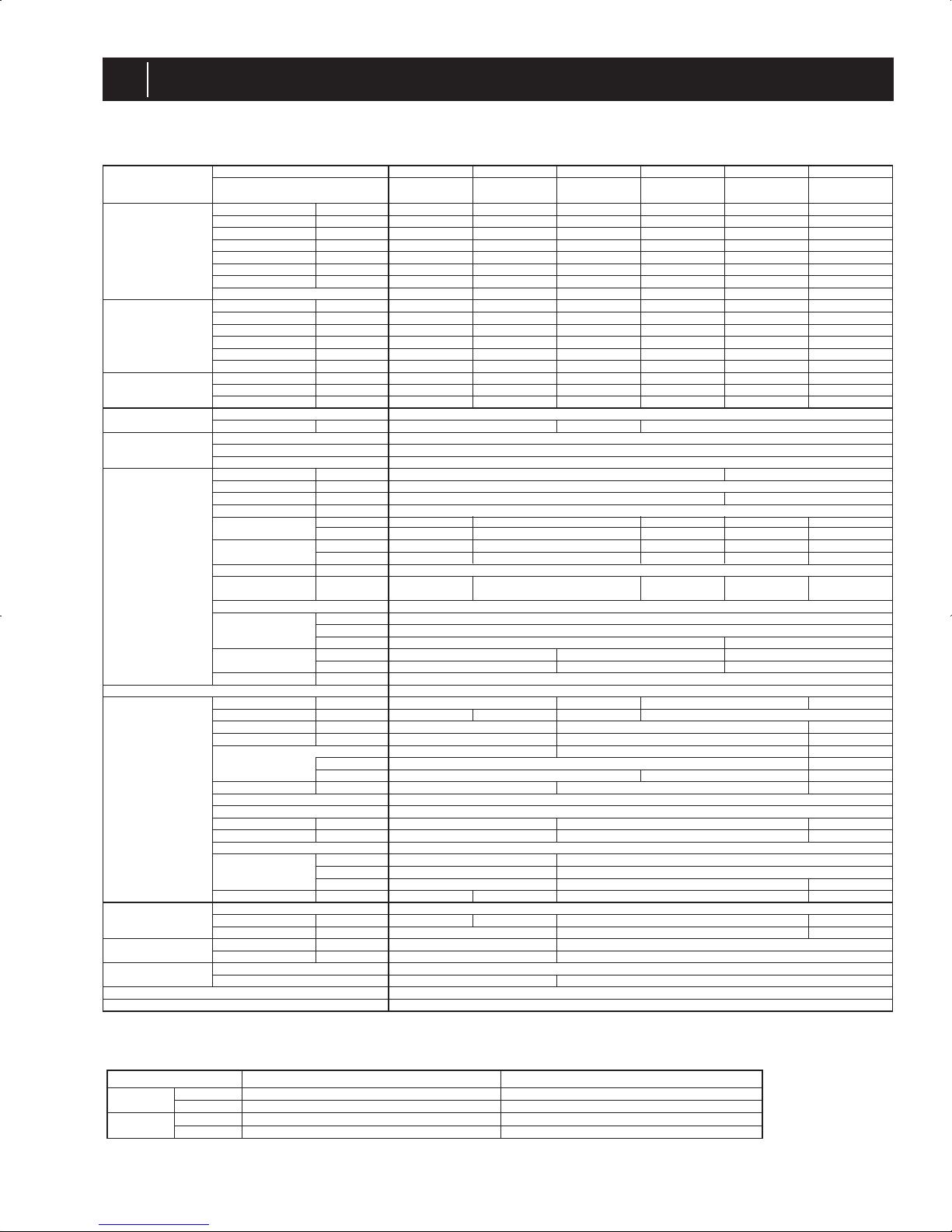
SPECIFICATIONS
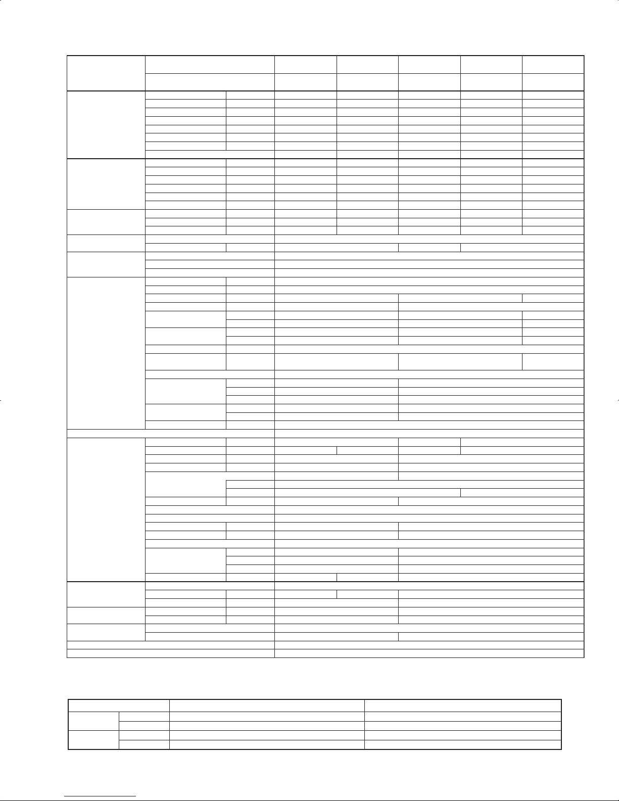
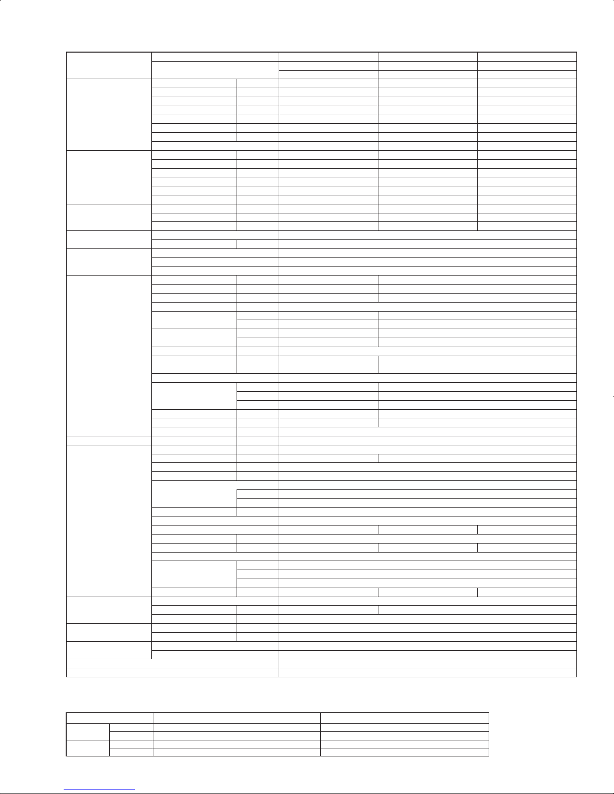
2-1. INVERTER CEILING CASSETTE TYPE
Model name Indoor unit
Outdoor unit
Cooling
Max. Capacity Btu/h
Rated Capacity Btu/h
Min. Capacity Btu/h
Total Input W
EER Btu/h/W
SEER Btu/h/W
Moisture Removal Pints/h
*1 SHF
Heating
Max. Capacity Btu/h
Rated Capacity Btu/h
Min. Capacity Btu/h
Total Input W
COP W/W
*1
HSPF (4/5)
Btu/h/W
Heating
Rated Capacity Btu/h
at low ambient
Total Input W
*2 COP W/W
Power supply
Phase, Cycle, Voltage
Breaker size A
Voltage
Indoor - Outdoor S1-S2
Indoor - Outdoor S2-S3
Indoor - Remote Controller
Indoor unit
MCA A
MOCP A
Fan Motor F.L.A.
Fan Motor Output W
Air flow DRY
CFM
(
Lo-M2-M1-Hi) WET
Air flow DRY
(
Lo-M2-M1-Hi) WET
CFM
CMM
CMM
External pressure Pa
Sound level dB(A
)
(
Lo-M2-M1-Hi
)
External finish (Panel
)
Dimension W : mm [inch]
Unit (Panel
)
D : mm [inch]
H : mm [inch]
Weight kg
Unit (Panel
)
lbs
Field drain pipe size O.D.
mm [inch]
Remote Controller
Outdoor unit
MCA A
MOCP A
Fan Motor F.L.A.
Fan Motor Output W
Compressor
R.L.A
L.R.A.
Air flow CMM [CFM]
Refrigerant Control
Defrost Method
Sound level at cooling dB(A
)
Sound level at heating dB(A
)
External finish
Dimension
W : mm [inch]
D : mm [inch]
H : mm [inch]
Weight
kg [lbs]
kg [lbs, oz]
Refrigerant
Type
Charge
Oil
L [oz]
Refrigerant pipe size
Gas side O.D.
mm [inch]
Liquid side O.D.
mm [inch]
Refrigerant pipe length Height difference
Length
Refrigerant Piping
Connection Method
PLA-A12BA PLA-A18BA PLA-A24BA PLA-A30BA PLA-A36BA PLA-A42BA
PUY-A12NHA3
PUY-A12NHA3-BS
PUY-A18NHA3
PUY-A18NHA3-BS
PUY-A24NHA3
PUY-A24NHA3-BS
PUY-A30NHA3
PUY-A30NHA3-BS
PUY-A36NHA3
PUY-A36NHA3-BS
PUY-A42NHA3
PUY-A42NHA3-BS
12,000 18,000 24,000 30,000 35,000 42,000
12,000 18,000 24,000 30,000 35,000 42,000
6,000 8,000 12,000 12,000 12,000 18,000
1260 1940 2500 4100 4500 4600
9.5 9.3 9.6 7.3 7.8 9.1
13.5 14.2 13.6 13.6 14.2 14.4
1.7 3.0 5.1 7.2 8.1 10.9
0.84 0.81 0.76 0.73 0.74 0.71
------
------
------
------
------
------
------
------
-----1phase, 60Hz, 208/230V
15 25 30
AC 208 / 230V
DC24V
DC12V
12
15
0.51 1.00
50 120
390-420-460-530 420-490-570-640 490-570-640-740 710-810-920-1060 780-880-990-1090
350-390-420-490 390-460-530-600 460-530-600-710 670-770-880-1030 740-850-950-1060
11-12-13-15 12-14-16-18 14-16-18-21 20-23-26-30 22-25-28-31
10-11-12-14 11-13-15-17 13-15-17-20 19-22-25-29 21-24-27-30
0
27-28-29-31 28-29-31-32 28-30-32-34 32-34-37-40 34-36-39-41
White Munsell 6.4Y 8.9 / 0.4
840 (950) [ 33-1/16 (37-3/8) ]
840 (950) [ 33-1/16 (37-3/8) ]
258 (35) [ 10-3/16 (1-3/8) ] 298 (35) [ 11-3/4 (1-3/8) ]
22 (6) 23 (6) 25 (6)
49 (13) 51 (13) 55 (13)
32 [ 1-1/4 ]
Attached in Grille
13 18 25 26
15 20 30 40
0.35 0.75 0.4 + 0.4
40 75 86 + 86
SNB130FPBM1 TNB220FLHM ANV33FDPMT
12 20
14 17.5 27.5
34 [1,200] 55 [1,940]
100 [3,530]
Linear Expansion Valve
-
46 48 51
--Ivory Munsell 3Y 7.8/1.1
800 [31-1/2] 950 [37-3/8]
330+23 [13 + 7/8] 330+30 [13 + 1-3/16]
600 [23-5/8] 943 [37-1/8] 1350 [53-1/8]
41 [90] 44 [97] 74 [163]
117 [258]
R410A
1.3 [2 lbs 14 oz] 1.7 [3 lbs 12 oz] 3.0 [6 lbs 10 oz]
4.5 [10 lbs]
0.65 (MEL56) [20] 0.87 (FV50S) [28]
1.4 (FV50S) [45]
12.7 [1/2] 15.88 [5/8]
6.35 [1/4] 9.52 [3/8]
Max. 30m [Max.100ft]
Max. 30m [Max.100ft] Max. 50 [Max.165ft]
Not Supplied
Flared
NOTES : *1.Rating conditions (cooling)-Indoor : D.B. 26.7:(80°F), W.B. 19.4:(67°F) Outdoor : D.B. 35:(95°F), W.B. 23.9:(75°F)
(heating)-Indoor : D.B. 21.1:(70°F), W.B. 15.6:(60°F) Outdoor : D.B. 8.3:(47°F), W.B. 6.1:(43°F)
*2.Rating conditions(heating)-Indoor : D.B. 21.1:(70°F), W.B. 15.6:(60°F) Outdoor : D.B. -8.3:(17°F), W.B. -9.4:(15°F)
Operating range
Indoor intake air temperature
D.B. 35:(95°F), W.B. 21.7:(71°F)
D.B. 19.4:(67°F), W.B. 13.9:(57°F)
D.B. 26.7:(80°F), W.B. 19.4:(67°F)
D.B. 21.1:(70°F), W.B. 15.6:(60°F)
Outdoor intake air temperature
D.B. 46:(115°F)
D.B. -18:(0°F)*
D.B. 21.1:(70°F), W.B. 15:(59°F)
D.B. -11.1:(12°F), W.B. -12.2:(10°F)
Cooling
Heating
Maximum
Minimum
Maximum
Minimum
* In case that the wind baffle is installed. (In case that the wind baffle is not installed, the minimum temperature will be -5:(23°F)DB.)
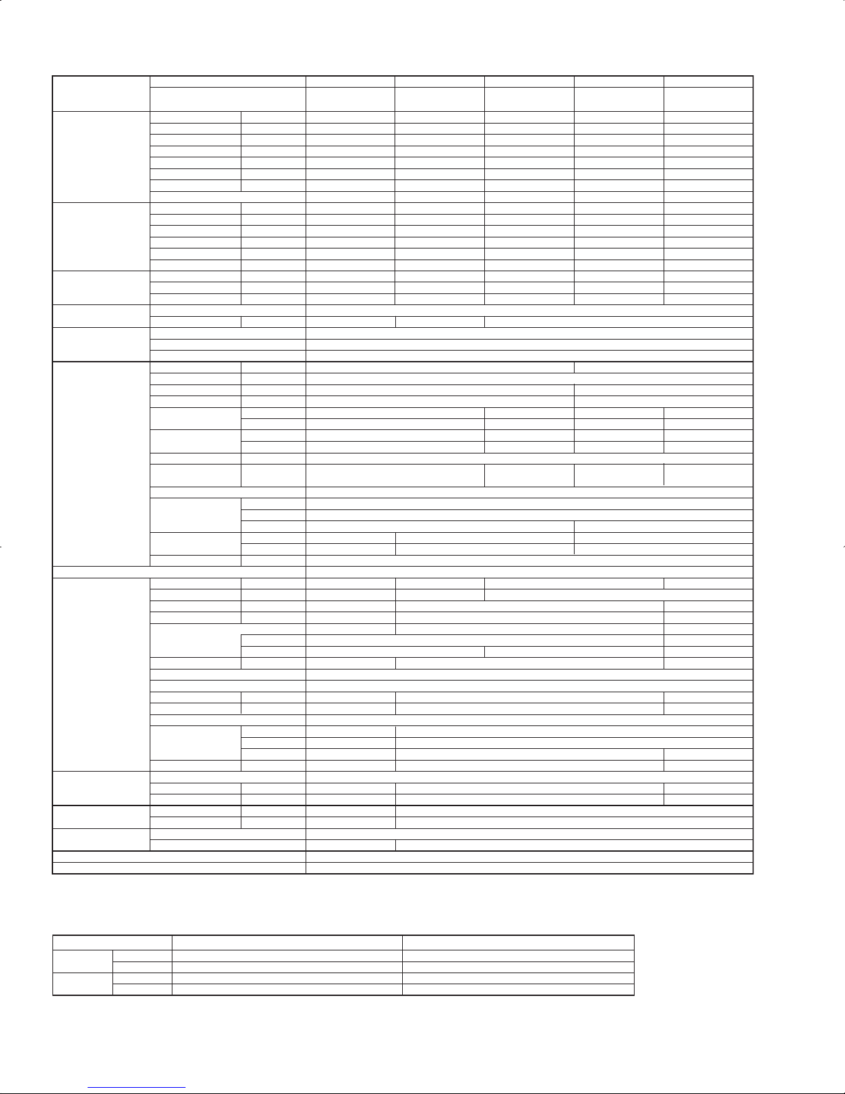
4
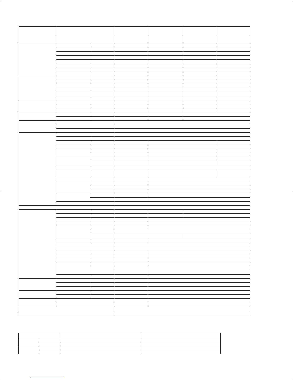
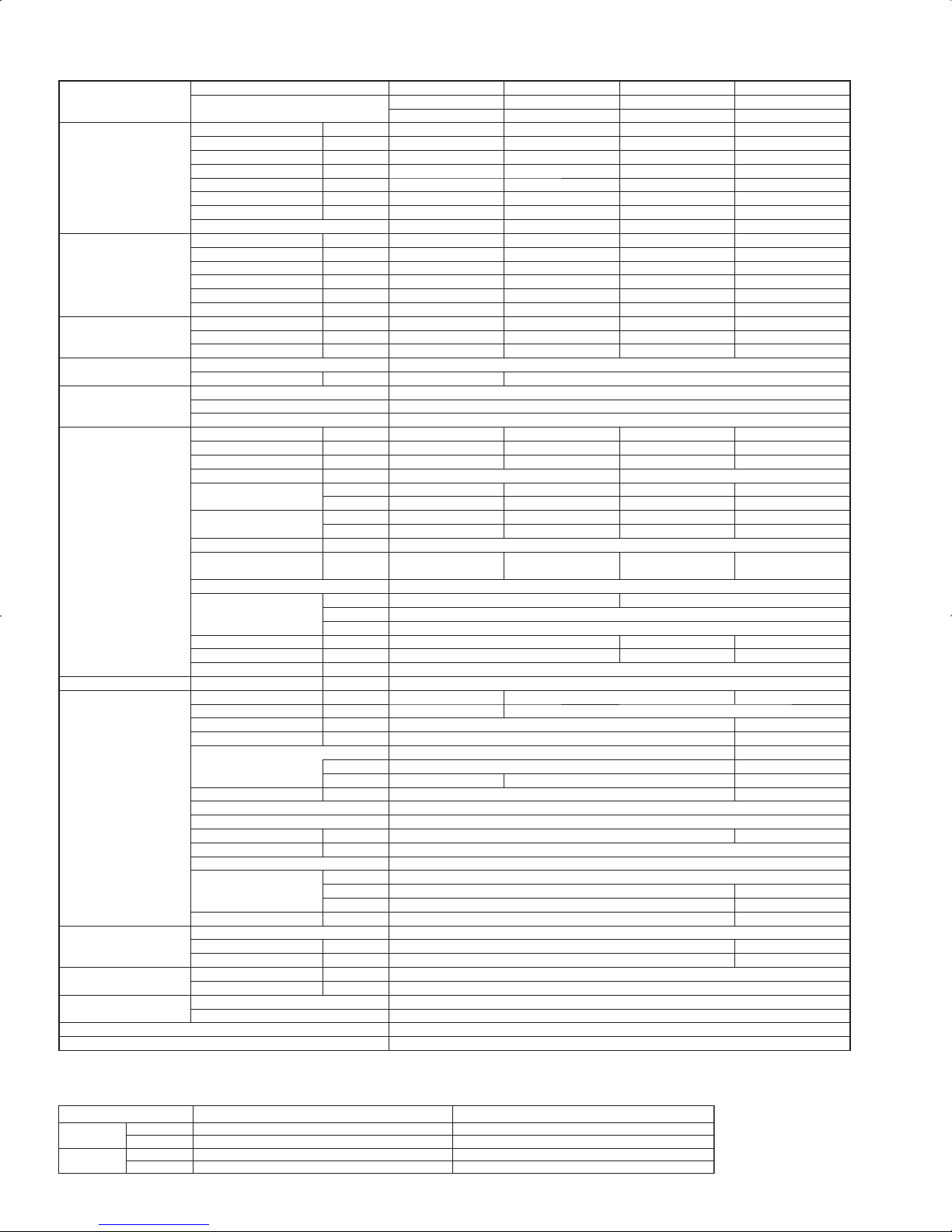
Model name Indoor unit
Outdoor unit
Cooling
Max. Capacity Btu/h
Rated Capacity Btu/h
Min. Capacity Btu/h
Total Input W
EER Btu/h/W
SEER Btu/h/W
Moisture Removal Pints/h
*1 SHF
Heating
Max. Capacity Btu/h
Rated Capacity Btu/h
Min. Capacity Btu/h
Total Input W
COP W/W
*1
HSPF (4/5)
Btu/h/W
Heating
Rated Capacity Btu/h
at low ambient
Total Input W
*2 COP W/W
Power supply
Phase, Cycle, Voltage
Breaker size A
Voltage
Indoor - Outdoor S1-S2
Indoor - Outdoor S2-S3
Indoor - Remote Controller
Indoor unit
MCA A
MOCP A
Fan Motor F.L.A.
Fan Motor Output W
Air flow DRY CFM
(
Lo-M2-M1-Hi) WET CFM
Air flow DRY CMM
(
Lo-M2-M1-Hi) WET CMM
External pressure Pa
Sound level dB(A
)
(
Lo-M2-M1-Hi
)
External finish (Panel
)
Dimension W : mm [inch]
Unit (Panel
)
D : mm [inch]
H : mm [inch]
Weight kg
Unit (Panel
)
lbs
Field drain pipe size O.D.
mm [inch]
Remote Controller
Outdoor unit
MCA A
MOCP A
Fan Motor F.L.A.
Fan Motor Output W
Compressor
R.L.A
L.R.A.
Air flow CMM [CFM]
Refrigerant Control
Defrost Method
Sound level at cooling
dB(A
)
Sound level at heating
dB(A
)
External finish
Dimension
W : mm [inch]
D : mm [inch]
H : mm [inch]
Weight
kg [lbs]
kg [lbs, oz]
Refrigerant
Type
Charge
Oil
L [oz]
Refrigerant pipe size Gas side O.D.
mm [inch]
Liquid side O.D.
mm [inch]
Refrigerant pipe length
Height difference
Length
Refrigerant Piping
Connection Method
PLA-A18BA PLA-A24BA PLA-A30BA PLA-A36BA PLA-A42BA
PUZ-A18NHA3
PUZ-A18NHA3-BS
PUZ-A24NHA3
PUZ-A24NHA3-BS
PUZ-A30NHA3
PUZ-A30NHA3-BS
PUZ-A36NHA3
PUZ-A36NHA3-BS
PUZ-A42NHA3
PUZ-A42NHA3-BS
18,000 24,000 30,000 35,000 42,000
18,000 24,000 30,000 35,000 42,000
8,000 12,000 12,000 12,000 18,000
1940 2500 4100 4500 4600
9.3 9.6 7.3 7.8 9.1
14.2 13.6 13.6 14.2 14.4
3.0 5.1 7.2 8.1 10.9
0.81 0.76 0.73 0.74 0.71
20,000 28,000 34,000 38,000 48,000
19,000 26,000 32,000 37,000 45,000
8,000 12,000 12,000 12,000 18,000
1900 2570 3370 3300 4450
2.93 2.96 2.78 3.28 2.96
9.8 / 7.5 8.5 / 6.8 8.7 / 6.9 9.3 / 7.3 9.3 / 7.2
13,000 16,000 23,000 25,000 30,000
1590 2200 3050 3070 4300
2.40 2.14 2.20 2.37 2.05
1phase, 60Hz, 208/230V
15 25 30
AC 208 / 230V
DC24V
DC12V
12
15
0.51 1.00
50 120
420-490-570-640 490-570-640-740 710-810-920-1060 780-880-990-1090
390-460-530-600 460-530-600-710 670-770-880-1030 740-850-950-1060
12-14-16-18 14-16-18-21 20-23-26-30 22-25-28-31
11-13-15-17 13-15-17-20 19-22-25-29 21-24-27-30
0
28-29-31-32 28-30-32-34 32-34-37-40 34-36-39-41
White Munsell 6.4Y 8.9 / 0.4
840 (950) [ 33-1/16 (37-3/8) ]
840 (950) [ 33-1/16 (37-3/8) ]
258 (35) [ 10-3/16 (1-3/8) ] 298 (35) [ 11-3/4 (1-3/8) ]
22 (6) 23 (6) 25 (6)
49 (13) 51 (13) 55 (13)
32 [ 1-1/4 ]
Attached in Grille
13 18 25 26
15 30 40
0.35 0.75 0.4 + 0.4
40 75 86 + 86
SNB130FPBM1 TNB220FLHM ANV33FDPMT
12 20
14 17.5 27.5
34 [1,200] 55 [1,940] 100 [3,530]
Linear Expansion Valve
Reverse Cycle
46 48 51
47 50 55
Ivory Munsell 3Y 7.8/1.1
800 [31-1/2] 950 [37-3/8]
330+23 [13 + 7/8] 330+30 [13 + 1-3/16]
600 [23-5/8] 943 [37-1/8] 1350 [53-1/8]
45 [99] 75 [165] 118 [260]
R410A
1.7 [3 lbs 12 oz] 3.0 [6 lbs 10 oz] 4.5 [10 lbs]
0.65 (MEL56) [20] 0.87 (FV50S) [28] 1.4 (FV50S) [45]
12.7 [1/2] 15.88 [5/8]
6.35 [1/4] 9.52 [3/8]
Max. 30m [Max.100ft]
Max. 30m [Max.100ft]
Max. 50 [Max.165ft]
Not Supplied
Flared
NOTES : *1.Rating conditions (cooling)-Indoor : D.B. 26.7:(80°F), W.B. 19.4:(67°F) Outdoor : D.B. 35:(95°F), W.B. 23.9:(75°F)
(heating)-Indoor : D.B. 21.1:(70°F), W.B. 15.6:(60°F) Outdoor : D.B. 8.3:(47°F), W.B. 6.1:(43°F)
*2.Rating conditions(heating)-Indoor : D.B. 21.1:(70°F), W.B. 15.6:(60°F) Outdoor : D.B. -8.3:(17°F), W.B. -9.4:(15°F)
Operating range
* In case that the wind baffle is installed. (In case that the wind baffle is not installed, the minimum temperature will be -5:(23°F)DB.)
Cooling
Heating
Maximum
Minimum
Maximum
Minimum
Indoor intake air temperature
D.B. 35:(95°F), W.B. 21.7:(71°F)
D.B. 19.4:(67°F), W.B. 13.9:(57°F)
D.B. 26.7:(80°F), W.B. 19.4:(67°F)
D.B. 21.1:(70°F), W.B. 15.6:(60°F)
Outdoor intake air temperature
D.B. 46:(115°F)
D.B. -18:(0°F)*
D.B. 21.1:(70°F), W.B. 15:(59°F)
D.B. -11.1:(12°F), W.B. -12.2:(10°F)
5
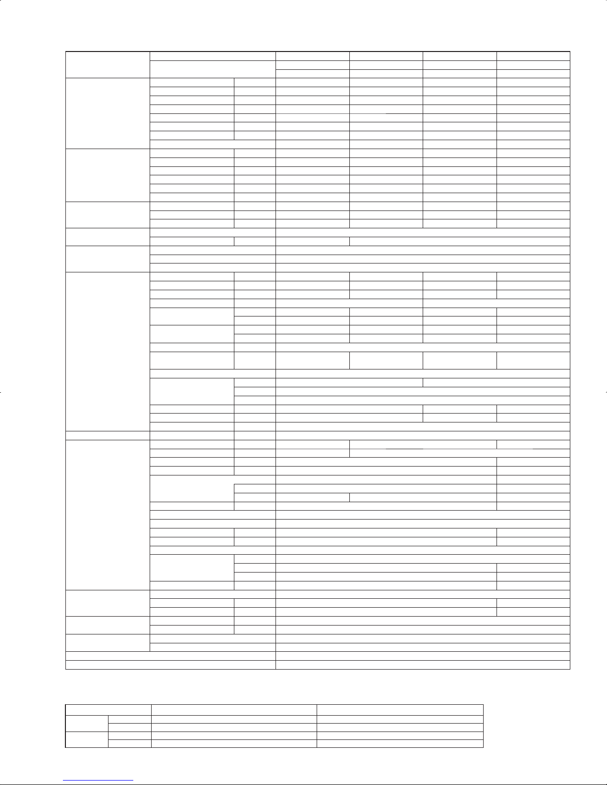
2-2. INVERTER WALL-MOUNTED TYPE
Model name
Indoor unit
PKA-A12HAL
PKA-A12HA
PKA-A18HAL
PKA-A18HA
PKA-A24KAL
PKA-A24KA
PKA-A30KAL
PKA-A30KA
PKA-A36KAL
PKA-A36KA
Outdoor unit
PUY-A12NHA3-BS
PUY-A12NHA3
PUY-A18NHA3-BS
PUY-A18NHA3
PUY-A24NHA3-BS
PUY-A24NHA3
PUY-A30NHA3-BS
PUY-A30NHA3
PUY-A36NHA3-BS
PUY-A36NHA3
Cooling Max. Capacity Btu/h 12,000 18,000 24,000 30,000 34,200
Rated Capacity Btu/h 12,000 18,000 24,000 30,000 34,200
Min. Capacity Btu/h 6,000 8,000
2240
8.0
15.3
5.2
0.68
12,000
2270
10.6
17.0
5.0
0.77
12,000
4130
7.3
15.5
8.1
0.70
12,000
5030
6.8
14.0
9.2
0.70
Total Input W
EER Btu/h/W
SEER Btu/h/W
Moisture Removal Pints/h
*1 SHF
Heating Max. Capacity Btu/h
-----
Rated Capacity Btu/h
-----
Min. Capacity Btu/h
-----
Total Input W
-----
COP W/W
-----
*1 HSPF (4/5) Btu/h/W
-----
Heating Rated Capacity Btu/h
-----
at low ambient Total Input W
-----
*2 COP W/W
-----
Power supply
Phase, Cycle, Voltage 1phase , 60Hz , 208/230V
Breaker size A 15 25 30
Voltage
Indoor - Outdoor S1-S2 AC 208 / 230V
Indoor - Outdoor S2-S3 DC24V
Indoor - Remote Controller DC12V : Wired type
Indoor unit
MCA A 1
MOCP A 15
Fan Motor F.L.A. 0.33 0.36 0.57
Fan Motor Output W 30 56
Air flow DRY
CMM 9-10.5-12 18-20-22 20-23-26
(Lo-Mid-Hi) WET CMM 8-9.5-11 16-18-20 18-21-23
Air flow DRY
CFM 320-370-425 635-705-775 705-810-920
(Lo-Mid-Hi) WET CFM 290-335-380 570-635-700 635-730-830
External pressure Pa 0
Sound level
dB(A) 36-40-43 39-42-45 43-46-49
(Lo-Mid-Hi)
External finish (Panel) White Munsell 1.0Y 9.2/0.2
Dimension W : mm [inch] 898 [35-3/8] 1170 [46-1/16]
Unit (Panel) D : mm [inch] 295 [11-5/8]249 [9-13/16]
H : mm [inch]
365 [14-3/8]295 [11-5/8]
Weight kg 13 21
Unit (Panel) lbs 29 46
Field drain pipe size I.D. mm [inch] 16 [5/8]
Remote Controller
Attached in Indoor Unit
Outdoor unit MCA A 13 18 25
MOCP A152030 40
Fan Motor F.L.A. 0.35 0.75
Fan Motor Output W 40 75
Compressor SNB130FPBM1 TNB220FLHM
R.L.A 12
L.R.A. 14 17.5
Air flow CMM [CFM] 34 [1,200] 55 [1,940]
Refrigerant Control Linear Expansion Valve
Defrost Method
Sound level at cooling dB(A) 46 48
Sound level at heating dB(A)
--
External finish
Ivory Munsell 3Y 7.8/1.1
Dimension
W : mm [inch]
800 [31-1/2] 950 [37-3/8]
D : mm [inch]
330+23 [13 + 7/8] 330+30 [13 + 1-3/16]
H : mm [inch]
600 [23-5/8] 943 [37-1/8]
Weight kg [lbs]
kg [lbs, oz]
41 [90] 44 [97] 74[163]
Refrigerant Type R410A
Charge
1.3 [2 lbs 14 oz] 1.7 [3 lbs 12 oz] 3.0 [6 lbs 10 oz]
Oil L [oz]
0.65 (MEL56) [20] 0.87 (FV50S) [28]
Refrigerant pipe size Gas side O.D. mm [inch] 12.7 [1/2] 15.88 [5/8]
Liquid side O.D. mm [inch] 6.35 [1/4] 9.52 [3/8]
Refrigerant pipe length Height difference Max. 30m [Max. 100ft]
Length Max. 30m [Max. 100ft] Max. 50m [Max. 165ft]
Refrigerant Piping Not Supplied
Connection Method Flared
119 0
10.1
15.2
2.0
0.81
NOTES : *1.Rating conditions (cooling)-Indoor : D.B. 26.7:(80°F), W.B. 19.4:(67°F) Outdoor : D.B. 35:(95°F), W.B. 23.9:(75°F)
(heating)-Indoor : D.B. 21.1:(70°F), W.B. 15.6:(60°F) Outdoor : D.B. 8.3:(47°F), W.B. 6.1:(43°F)
*2.Rating conditions(heating)-Indoor : D.B. 21.1:(70°F), W.B. 15.6:(60°F) Outdoor : D.B. -8.3:(17°F), W.B. -9.4:(15°F)
Operating range
Indoor intake air temperature
D.B. 35:(95°F), W.B. 21.7:(71°F)
D.B. 19.4:(67°F), W.B. 13.9:(57°F)
D.B. 26.7:(80°F), W.B. 19.4:(67°F)
D.B. 21.1:(70°F), W.B. 15.6:(60°F)
Outdoor intake air temperature
D.B. 46:(115°F)
D.B. -18:(0°F)*
D.B. 21.1:(70°F), W.B. 15:(59°F)
D.B. -11.1:(12°F), W.B. -12.2:(10°F)
Cooling
Heating
Maximum
Minimum
Maximum
Minimum
* In case that the wind baffle is installed. (In case that the wind baffle is not installed, the minimum temperature will be -5:(23°F)DB.)
6
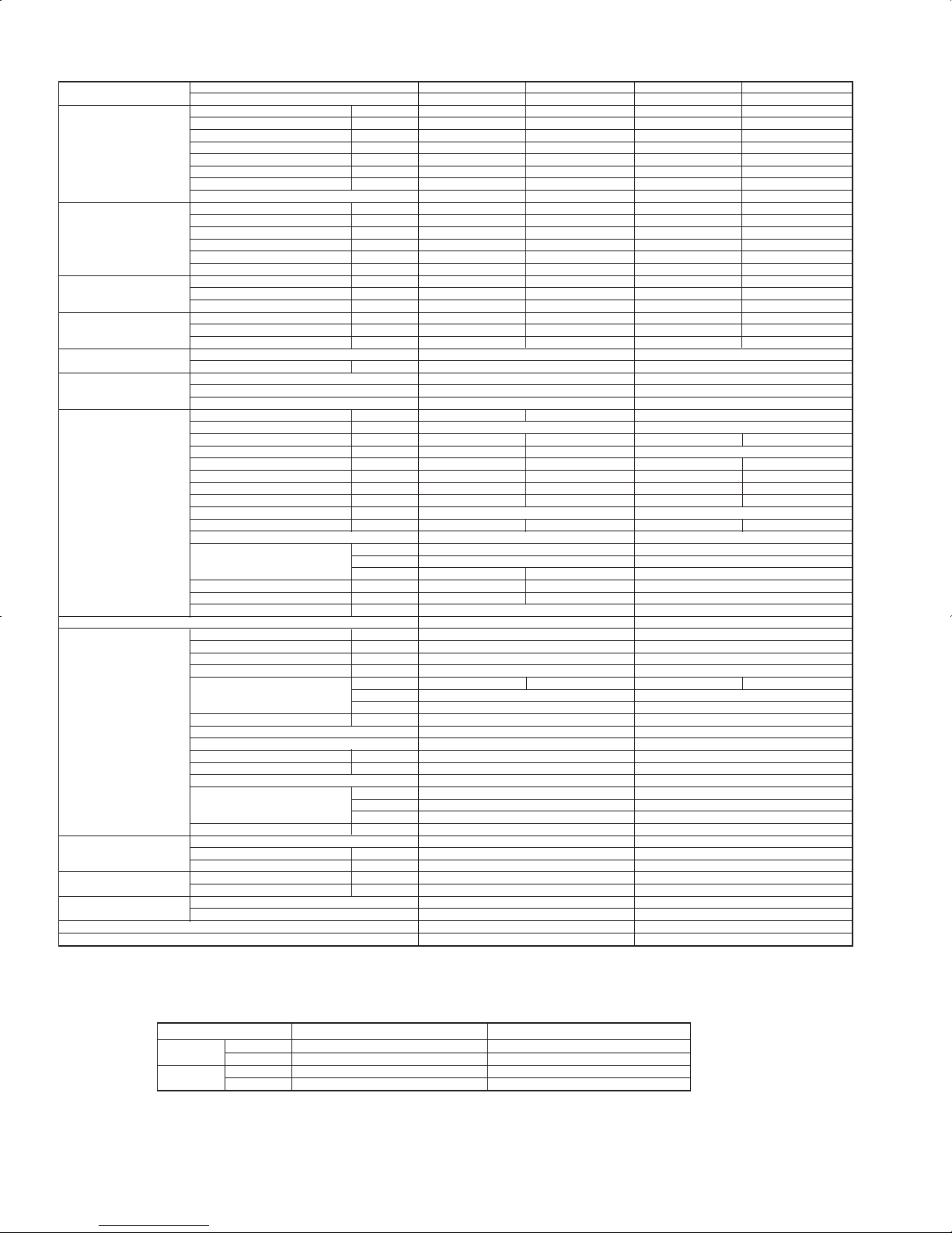
NOTES : *1.Rating conditions (cooling)-Indoor : D.B. 26.7:(80°F), W.B. 19.4:(67°F) Outdoor : D.B. 35:(95°F), W.B. 23.9:(75°F)
(heating)-Indoor : D.B. 21.1:(70°F), W.B. 15.6:(60°F) Outdoor : D.B. 8.3:(47°F), W.B. 6.1:(43°F)
*2.Rating conditions(heating)-Indoor : D.B. 21.1:(70°F), W.B. 15.6:(60°F) Outdoor : D.B. -8.3:(17°F), W.B. -9.4:(15°F)
Operating range
Indoor intake air temperature
D.B. 35:(95°F), W.B. 21.7:(71°F)
D.B. 19.4:(67°F), W.B. 13.9:(57°F)
D.B. 26.7:(80°F), W.B. 19.4:(67°F)
D.B. 21.1:(70°F), W.B. 15.6:(60°F)
Outdoor intake air temperature
D.B. 46:(115°F)
D.B. -18:(0°F)*
D.B. 21.1:(70°F), W.B. 15:(59°F)
D.B. -11.1:(12°F), W.B. -12.2:(10°F)
Cooling
Heating
Maximum
Minimum
Maximum
Minimum
* In case that the wind baffle is installed. (In case that the wind baffle is not installed, the minimum temperature will be -5:(23°F)DB.)
Model name
Indoor unit
PKA-A18HAL
PKA-A18HA
PKA-A24KAL
PKA-A24KA
PKA-A30KAL
PKA-A30KA
PKA-A36KAL
PKA-A36KA
Outdoor unit
PUZ-A18NHA3-BS
PUZ-A18NHA3
PUZ-A24NHA3-BS
PUZ-A24NHA3
PUZ-A30NHA3-BS
PUZ-A30NHA3
PUZ-A36NHA3-BS
PUZ-A36NHA3
Cooling Max. Capacity Btu/h 18,000 24,000 30,000 34,200
Rated Capacity Btu/h 18,000 24,000 30,000 34,200
Min. Capacity Btu/h 8,000
2240
8.0
15.3
5.2
0.68
12,000
2270
10.6
17.0
5.0
0.77
12,000
4130
7.3
15.5
8.1
0.70
12,000
5030
6.8
14.0
9.2
0.70
Total Input W
EER Btu/h/W
SEER Btu/h/W
Moisture Removal Pints/h
*1 SHF
Heating Max. Capacity Btu/h 20,000 28,000 34,000 38,000
Rated Capacity Btu/h 19,000 26,000 32,000 37,000
Min. Capacity Btu/h 8,000
1970
2.83
9.5 / 7.6
12,000
2330
3.27
10.8 / 8.6
12,000
3150
2.98
8.9 / 7.1
2850
2.37
12,000
3610
3.00
9.3 / 7.5
Total Input W
COP W/W
*1 HSPF
(4/5)
Btu/h/W
Heating Rated Capacity Btu/h 13,000
1670
2.28
18,000
2200
2.40
23,000 25,000
3030
2.42
at low ambient Total Input W
*2 COP W/W
Power supply Phase, Cycle, Voltage 1phase , 60Hz , 208/230V
Breaker size A 15 25 30
Voltage
Indoor - Outdoor S1-S2
AC 208 / 230V
Indoor - Outdoor S2-S3
DC24V
Indoor - Remote Controller DC12V : Wired type
Indoor unit MCA A
MOCP A
Fan Motor F.L.A.
Fan Motor Output W
Air flow DRY
CMM
(Lo-Mid-Hi) WET CMM
Air flow DRY
CFM
(Lo-Mid-Hi) WET CFM
External pressure Pa
Sound level
dB(A)
(Lo-Mid-Hi)
External finish (Panel)
Dimension W : mm [inch]
Unit (Panel) D : mm [inch]
H : mm [inch]
Weight kg
Unit (Panel) lbs
Field drain pipe size I.D.
mm [inch]
Remote Controller Attached in Indoor Unit
Outdoor unit MCA A 13 18 25
MOCP A 20 30 40
Fan Motor F.L.A. 0.35 0.75
Fan Motor Output W 40 75
Compressor SNB130FPBM1 TNB220FLHM
R.L.A 12
L.R.A. 14 17.5
Air flow CMM [CFM] 34 [1,200] 55 [1,940]
Refrigerant Control Linear Expansion Valve
Defrost Method Reverse Cycle
Sound level at cooling dB(A) 46 48
Sound level at heating dB(A) 47 50
External finish Ivory Munsell 3Y 7.8/1.1
Dimension
W : mm [inch]
800 [31-1/2] 950 [37-3/8]
D : mm [inch]
330+23 [13 + 7/8] 330+30 [13 + 1-3/16]
H : mm [inch]
600 [23-5/8] 943 [37-1/8]
Weight kg [lbs]
kg [lbs, oz]
45 [99] 75 [165]
Refrigerant Type
R410A
Charge
1.7 [3 lbs 12 oz] 3.0 [6 lbs 10 oz]
Oil
L [oz] 0.65 (MEL56) [20] 0.87 (FV50S) [28]
Refrigerant pipe size Gas side O.D.
mm [inch] 12.7 [1/2] 15.88 [5/8]
Liquid side O.D.
mm [inch] 6.35 [1/4] 9.52 [3/8]
Refrigerant pipe length Height difference
Max. 30m [Max. 100ft]
Length
Max. 30m [Max. 100ft] Max. 50m [Max. 165ft]
Refrigerant Piping
Not Supplied
Connection Method
Flared
1
15
0.33 0.36 0.57
30 56
9-10.5-12 18-20-22 20-23-26
8-9.5-11 16-18-20 18-21-23
320-370-425 635-705-775 705-810-920
290-335-380 570-635-700
635-730-830
0
36-40-43 39-42-45 43-46-49
White Munsell 1.0Y 9.2/0.2
898 [35-3/8]
1170 [46-1/16]
295 [11-5/8]249 [9-13/16]
365 [14-3/8]295 [11-5/8]
13
21
29
46
16 [5/8]
7
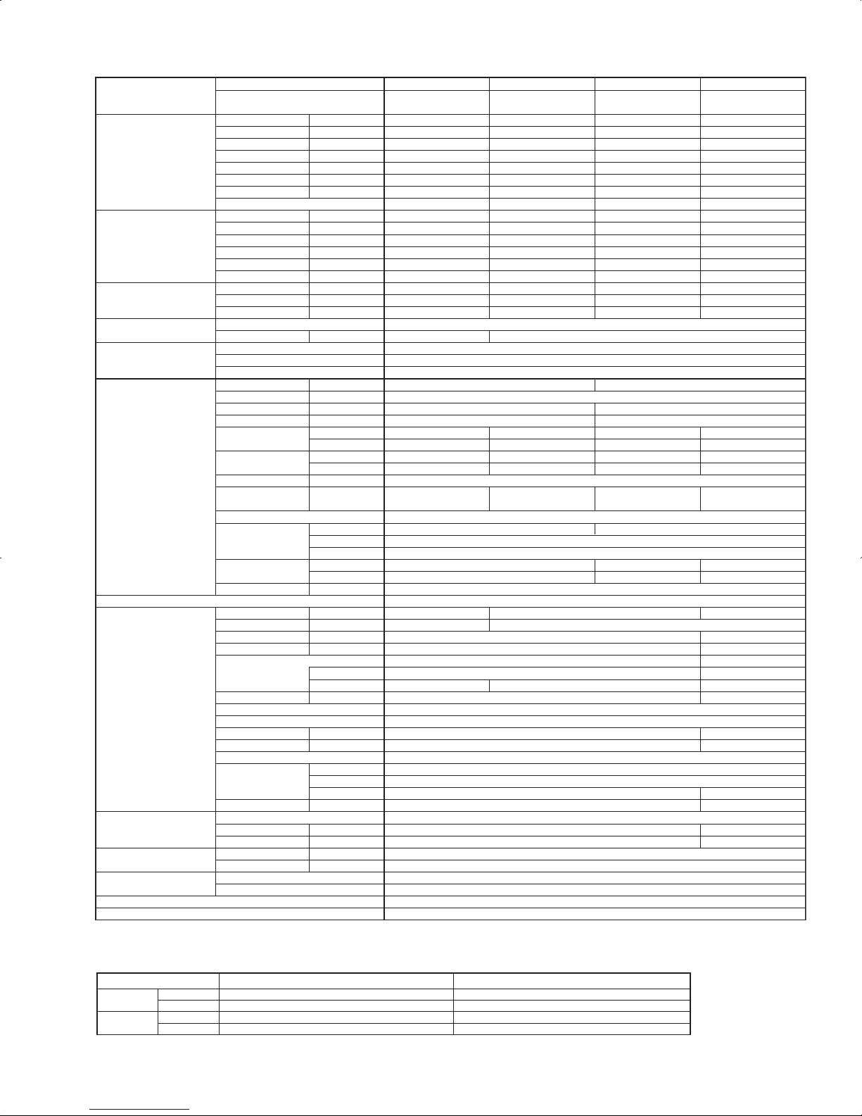
Model name Indoor unit
PCA-A24KA PCA-A30KA PCA-A36KA PCA-A42KA
Outdoor unit
PUY-A24NHA3-BS
PUY-A24NHA3
PUY-A30NHA3-BS
PUY-A30NHA3
PUY-A36NHA3-BS
PUY-A36NHA3
PUY-A42NHA3-BS
PUY-A42NHA3
Cooling Max. Capacity Btu/h 24,000 30,000 35,000 42,000
Rated Capacity Btu/h 24,000 30,000 35,000 42,000
Min. Capacity Btu/h 12,000 12,000 12,000 18,000
Total Input W 2340 3760 4630 4110
EER Btu/h/W 10.3 8.0 7.6 10.2
SEER Btu/h/W 16.8 14.5 14.4 15.8
Moisture Removal Pints/h 5.8 8.3 8.5 11.7
*1 SHF 0.73 0.69 0.73 0.69
Heating Max. Capacity Btu/h
----
Rated Capacity Btu/h
----
Min. Capacity Btu/h
----
Total Input W
----
COP W/W
----
*1 HSPF (4/5) Btu/h/W
----
Heating Rated Capacity Btu/h
----
at low ambient Total Input W
----
*2 COP W/W
----
Power supply Phase, Cycle, Voltage 1phase , 60Hz , 208/230V
Breaker size A 25 30
Voltage Indoor - Outdoor S1-S2 AC 208 / 230V
Indoor - Outdoor S2-S3 DC24V
Indoor - Remote Controller DC12V
Indoor unit MCA A 1 2
MOCP A 15
Fan Motor F.L.A. 0.54 0.97
Fan Motor Output W 95 160
Air flow DRY CMM 15-16-17-19 22-24-26-28
(
Lo-M2-M1-Hi) WET CMM 14-15-16-18 20-22-24-26
Air flow DRY CFM 530-565-600-670 775-850-920-990
(
Lo-M2-M1-Hi) WET CFM 495-530-565-635 705-775-850-920
External pressure Pa 0
Sound level dB(A
)
33-35-37-40
16-17-18-20
15-16-17-19
565-600-635-705
530-565-600-670
35-37-39-41 37-39-41-43
23-25-27-29
21-23-25-27
810-885-955-1025
740-810-885-955
39-41-43-45
(
Lo-M2-M1-Hi
)
External finish (Panel
)
White Munsell 6.4Y 8.9/0.4
Dimension W : mm [inch] 1600 [63]1280 [50-3/8]
Unit (Panel
)
D : mm [inch] 680 [26-3/4]
H : mm [inch] 230 [9-1/16]
Weight kg 32 36
Unit (Panel
)
lbs 71 79
38
84
Field drain pipe size O.D.
mm [inch] 26 [1-1/32]
Remote Controller Attached in Indoor Unit
Outdoor unit MCA A 18 25 26
MOCP A 30 40
Fan Motor F.L.A. 0.75 0.4 + 0.4
Fan Motor Output W 75 86 + 86
Compressor TNB220FLHM ANV33FDPMT
R.L.A 12 20
L.R.A. 14 17.5 27.5
Air flow CMM [CFM] 55 [1,940] 100 [3,530]
Refrigerant Control Linear Expansion Valve
Defrost Method
-
Sound level at cooling
dB(A
)
48 51
Sound level at heating
dB(A
)
-External finish Ivory Munsell 3Y 7.8/1.1
Dimension W : mm [inch] 950 [37-3/8]
D : mm [inch] 330+30 [13 + 1-3/16]
H : mm [inch] 943 [37-1/8] 1350 [53-1/8]
Weight kg [lbs]
kg [lbs]
74[163] 117 [258]
Refrigerant Type R410A
Charge 3.0 [6 lbs 10 oz] 4.5 [10 lbs]
Oil L [oz] 0.87 (FV50S) [28] 1.4 (FV50S) [45]
Refrigerant pipe size Gas side O.D. mm [inch] 15.88 [5/8]
Liquid side O.D. mm [inch] 9.52 [3/8]
Refrigerant pipe length Height difference Max. 30m [Max. 100ft]
Length Max. 50m [Max. 165ft]
Refrigerant Piping Not Supplied
Connection Method Flared
2-3. INVERTER CEILING-SUSPENDED TYPE
NOTES : *1.Rating conditions (cooling)-Indoor : D.B. 26.7:(80°F), W.B. 19.4:(67°F) Outdoor : D.B. 35:(95°F), W.B. 23.9:(75°F)
(heating)-Indoor : D.B. 21.1:(70°F), W.B. 15.6:(60°F) Outdoor : D.B. 8.3:(47°F), W.B. 6.1:(43°F)
*2.Rating conditions(heating)-Indoor : D.B. 21.1:(70°F), W.B. 15.6:(60°F) Outdoor : D.B. -8.3:(17°F), W.B. -9.4:(15°F)
Operating range
Indoor intake air temperature
D.B. 35:(95°F), W.B. 21.7:(71°F)
D.B. 19.4:(67°F), W.B. 13.9:(57°F)
D.B. 26.7:(80°F), W.B. 19.4:(67°F)
D.B. 21.1:(70°F), W.B. 15.6:(60°F)
Outdoor intake air temperature
D.B. 46:(115°F)
D.B. -18:(0°F)*
D.B. 21.1:(70°F), W.B. 15:(59°F)
D.B. -11.1:(12°F), W.B. -12.2:(10°F)
Cooling
Heating
Maximum
Minimum
Maximum
Minimum
* In case that the wind baffle is installed. (In case that the wind baffle is not installed, the minimum temperature will be -5:(23°F)DB.)
8
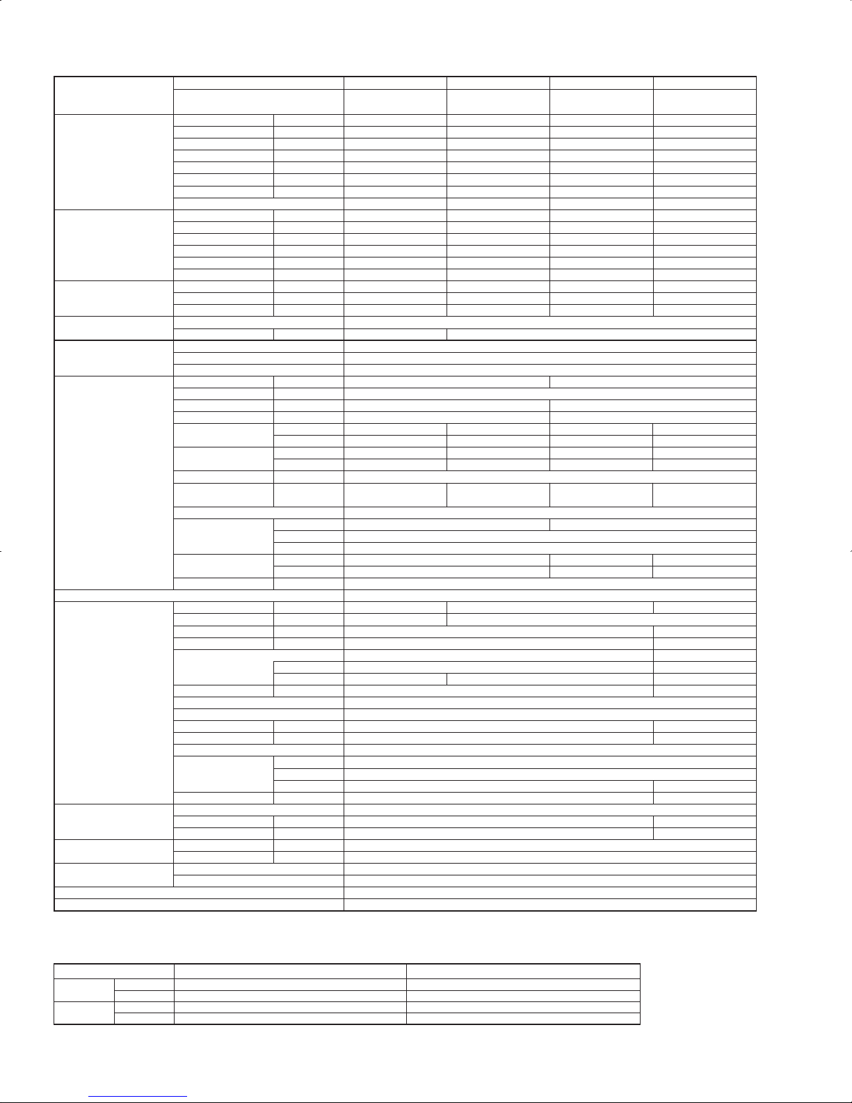
NOTES : *1.Rating conditions (cooling)-Indoor : D.B. 26.7:(80°F), W.B. 19.4:(67°F) Outdoor : D.B. 35:(95°F), W.B. 23.9:(75°F)
(heating)-Indoor : D.B. 21.1:(70°F), W.B. 15.6:(60°F) Outdoor : D.B. 8.3:(47°F), W.B. 6.1:(43°F)
*2.Rating conditions(heating)-Indoor : D.B. 21.1:(70°F), W.B. 15.6:(60°F) Outdoor : D.B. -8.3:(17°F), W.B. -9.4:(15°F)
Operating range
Indoor intake air temperature
D.B. 35:(95°F), W.B. 21.7:(71°F)
D.B. 19.4:(67°F), W.B. 13.9:(57°F)
D.B. 26.7:(80°F), W.B. 19.4:(67°F)
D.B. 21.1:(70°F), W.B. 15.6:(60°F)
Outdoor intake air temperature
D.B. 46:(115°F)
D.B. -18:(0°F)*
D.B. 21.1:(70°F), W.B. 15:(59°F)
D.B. -11.1:(12°F), W.B. -12.2:(10°F)
Cooling
Heating
Maximum
Minimum
Maximum
Minimum
* In case that the wind baffle is installed. (In case that the wind baffle is not installed, the minimum temperature will be -5:(23°F)DB.)
Model name Indoor unit
PCA-A24KA PCA-A30KA PCA-A36KA PCA-A42KA
Outdoor unit
PUZ-A24NHA3-BS
PUZ-A24NHA3
PUZ-A30NHA3-BS
PUZ-A30NHA3
PUZ-A36NHA3-BS
PUZ-A36NHA3
PUZ-A42NHA3-BS
PUZ-A42NHA3
Cooling
Max. Capacity Btu/h 24,000 30,000 35,000 42,000
Rated Capacity Btu/h 24,000 30,000 35,000 42,000
Min. Capacity Btu/h 12,000 12,000 12,000 18,000
Total Input W 2340 3760 4630 4110
EER Btu/h/W 10.3 8.0 7.6 10.2
SEER Btu/h/W 16.8 14.5 14.4 15.8
Moisture Removal Pints/h 5.8 8.3 8.5 11.7
*1 SHF 0.73 0.69 0.73 0.69
Heating
Max. Capacity Btu/h 28,000 34,000 38,000 48,000
Rated Capacity Btu/h 26,000 32,000 37,000 45,000
Min. Capacity Btu/h 12,000 12,000 12,000 18,000
Total Input W 2310 3210 3190 3830
COP W/W 3.30 2.92 3.40 3.44
*1 HSPF (4/5) Btu/h/W 10.9 / 8.9 9.2 / 7.1 10.2 / 8.1 10.2 / 8.3
Heating
Rated Capacity Btu/h 18,000 23,000 25,000 30,000
at low ambient
Total Input W 2220 2940 2800 3820
*2 COP W/W 2.38 2.29 2.62 2.30
Power supply
Phase, Cycle, Voltage 1phase , 60Hz , 208/230V
Breaker size A 25 30
Voltage
Indoor - Outdoor S1-S2 AC 208 / 230V
Indoor - Outdoor S2-S3 DC24V
Indoor - Remote Controller DC12V
Indoor unit
MCA A
MOCP A
Fan Motor F.L.A.
Fan Motor Output W
Air flow DRY CMM
(Lo-M2-M1-Hi) WET CMM
Air flow DRY CFM
(Lo-M2-M1-Hi) WET CFM
External pressure Pa
Sound level dB(A)
(Lo-M2-M1-Hi)
External finish (Panel)
Dimension W : mm [inch]
Unit (Panel) D : mm [inch]
H : mm [inch]
Weight kg
Unit (Panel) lbs
Field drain pipe size O.D.
mm [inch] 26 [1-1/32]
Remote Controller
Attached in Indoor Unit
Outdoor unit
MCA A 18 25 26
MOCP A 30 40
Fan Motor F.L.A. 0.75 0.4 + 0.4
Fan Motor Output W 75 86 + 86
Compressor TNB220FLHM ANV33FDPMT
R.L.A 12 20
L.R.A. 14 17.5 27.5
Air flow CMM [CFM] 55 [1,940] 100 [3,530]
Refrigerant Control Linear Expansion Valve
Defrost Method Reverse Cycle
Sound level at cooling dB(A) 48 51
Sound level at heating dB(A) 50 55
External finish Ivory Munsell 3Y 7.8/1.1
Dimension W : mm [inch] 950 [37-3/8]
D : mm [inch] 330+30 [13 + 1-3/16]
H : mm [inch] 943 [37-1/8] 1350 [53-1/8]
Weight kg [lbs]
kg [lbs]
75 [165] 118 [260]
Refrigerant
Type R410A
Charge 3.0 [6 lbs 10 oz] 4.5 [10 lbs]
Oil L [oz] 0.87 (FV50S) [28] 1.4 (FV50S) [45]
Refrigerant pipe size
Gas side O.D. mm [inch] 15.88 [5/8]
Liquid side O.D. mm [inch] 9.52 [3/8]
Refrigerant pipe length
Height difference Max. 30m [Max. 100ft]
Length Max. 50m [Max. 165ft]
Refrigerant Piping
Not Supplied
Connection Method
Flared
12
15
0.54 0.97
95 160
15-16-17-19 22-24-26-28
14-15-16-18 20-22-24-26
530-565-600-670 775-850-920-990
495-530-565-635 705-775-850-920
0
33-35-37-40
16-17-18-20
15-16-17-19
565-600-635-705
530-565-600-670
35-37-39-41 37-39-41-43
23-25-27-29
21-23-25-27
810-885-955-1025
740-810-885-955
39-41-43-45
White Munsell 6.4Y 8.9/0.4
1600 [63]1280 [50-3/8]
680 [26-3/4]
230 [9-1/16]
32 36
71 79
38
84
9
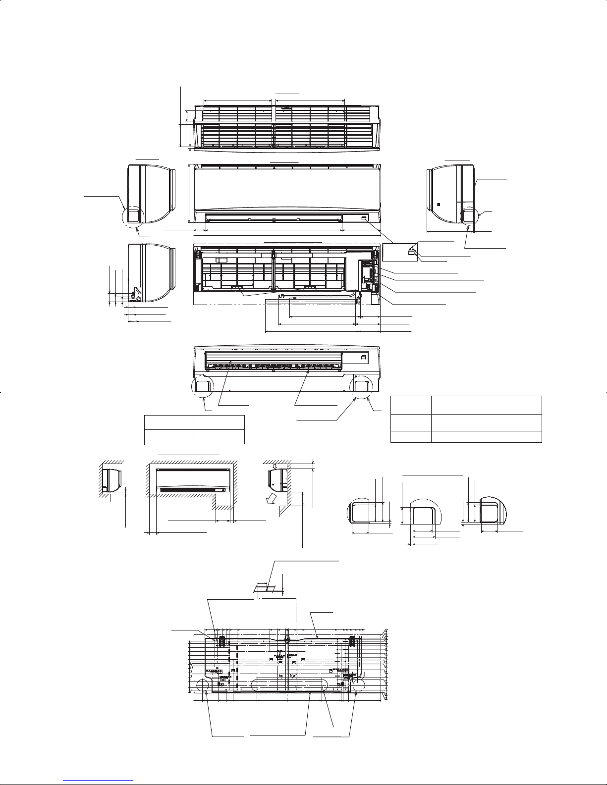
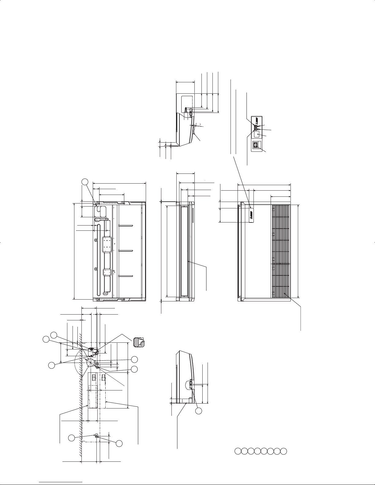
2-4. INVERTER CEILING CONCEALED TYPE (PEA/PEAD)
Model name
Indoor unit PEA-A12AA PEA-A18AA PEA-A18AA
Outdoor unit
PUY-A12NHA3 PUY-A18NHA3 PUZ-A18NHA3
PUY-A12NHA3-BS PUY-A18NHA3-BS PUZ-A18NHA3-BS
Cooling
Max. Capacity Btu/h 12,000 18,000 18,000
Rated Capacity Btu/h 12,000 18,000 18,000
Min. Capacity Btu/h 6,000 8,000 8,000
Total Input W 1240 2150 2150
EER Btu/h 9.7 8.4 8.4
SEER Btu/h 13.8 14.3 14.3
Moisture Removal Pints/h 2.47 3.26 3.26
SHF 0.77 0.80 0.80
Heating
Max. Capacity Btu/h - - 20,000
Rated Capacity Btu/h - - 19,000
Min. Capacity Btu/h - - 8,000
Total Input W - - 1540
COP W/W - - 3.61
HSPF(IV/V) Btu/h/W - - 10.0 / 8.0
Heating
at low ambient
Rated Capacity Btu/h - - 13,000
Total Input W - - 1520
COP W/W - - 2.51
Power supply
Phase,Cycle,Voltage 1phase, 60Hz, 208/230V
Breaker size A 15
Voltage
Indoor - Outdoor S1-S2 AC208 / 230V
Indoor - Outdoor S2-S3 DC24V
Indoor - Remote controller DC12V
Indoor unit
MCA A 1 2
MOCP A 15 15
Fan Motor F.L.A 0.57 0.74
Fan Motor Output W 96
Air fl ow DRY
(Lo-Mid-Hi) WET
CMM 7-9-11 12-15-18
CMM 6-8-10 11-14-17
Air fl ow DRY
(Lo-Mid-Hi) WET
CFM 247-317-388 423-529-635
CFM 222-285-349 381-476-572
External pressure in.WG [Pa] 0.02/0.06/0.14/0.20 [5/15/35/50]
Sound level
(Lo-Mid-Hi)
dB(A)
23-28-33 30-34-38
External fi nish Galvanized
Dimension
Unit (Panel)
W:mm[inch] 990[39] 1190[46-7/8]
D:mm[inch] 700[27-9/16] 700[27-9/16]
H:mm[inch] 200[7-7/8] 200[7-7/8]
Weight kg 21 27
Unit lbs 48 60
Field Drain pipe seize O.D.
mm[inch] 32 [1-9/32]
Remote Controller
Attached in indoor Unit
Outdoor unit
MCA A 13
MOCP A 15 20
Fan Motor F.L.A. 0.35
Fan Motor Output W 40
Compressor SNB130FPBM1
R.L.A. 12
L.R.A. 14
Air fl ow CMM[CFM] 34 [1,200]
Refrigerant Control Linear Expansion Valve
Defrost Method - - Reverse Cycle
Sound level at cooling dB(A) 46
Sound level at heating dB(A) - - 47
External fi nish Ivory Munsell 3Y 7.8/1.1
Dimension
W:mm[inch] 800 [31-1/2]
D:mm[inch] 330+23 [13+7/8]
H:mm[inch] 600 [23-5/8]
Weignt
kg[lbs]
41[90] 44[97] 45[99]
Refrigerant
Type R410A
Charge kg[lbs,oz] 1.3 [2lbs 14oz] 1.7 [3lbs 12oz]
Oil L[oz] 0.65 (MEL 56) [20]
Refrigerant pipe size
Gas side O.D. mm[inch] 12.7 [1/2]
Liquid side O.D. mm[inch] 6.35 [1/4]
Refrigerant pipe length
Height difference Max. 30m [Max.100ft]
Length Max. 30m [Max.100ft]
Refrigerant Piping
Not Supplied
Connection Method
Flared
NOTES : *1.Rating conditions (cooling)-Indoor : D.B. 26.7:(80°F), W.B. 19.4:(67°F) Outdoor : D.B. 35:(95°F), W.B. 23.9:(75°F)
(heating)-Indoor : D.B. 21.1:(70°F), W.B. 15.6:(60°F) Outdoor : D.B. 8.3:(47°F), W.B. 6.1:(43°F)
*2.Rating conditions(heating)-Indoor : D.B. 21.1:(70°F), W.B. 15.6:(60°F) Outdoor : D.B. -8.3:(17°F), W.B. -9.4:(15°F)
Operating range
Indoor intake air temperature
D.B. 35:(95°F), W.B. 21.7:(71°F)
D.B. 19.4:(67°F), W.B. 13.9:(57°F)
D.B. 26.7:(80°F), W.B. 19.4:(67°F)
D.B. 21.1:(70°F), W.B. 15.6:(60°F)
Outdoor intake air temperature
D.B. 46:(115°F)
D.B. -18:(0°F)*
D.B. 21.1:(70°F), W.B. 15:(59°F)
D.B. -11.1:(12°F), W.B. -12.2:(10°F)
Cooling
Heating
Maximum
Minimum
Maximum
Minimum
* In case that the wind baffle is installed. (In case that the wind baffle is not installed, the minimum temperature will be -5:(23°F)DB.)
*1
*1
*2
10
Model name
Indoor unit PEAD-A24AA PEAD-A30AA PEAD-A36AA PEAD-A42AA
Outdoor unit
PUY-A24NHA3 PUY-A30NHA3 PUY-A36NHA3 PUY-A42NHA3
PUY-A24NHA3-BS PUY-A30NHA3-BS PUY-A36NHA3-BS PUY-A42NHA3-BS
Cooling
Max. Capacity Btu/h 24,000 30,000 35,000 42,000
Rated Capacity Btu/h 24,000 30,000 35,000 42,000
Min. Capacity Btu/h 12,000 12,000 12,000 18,000
Total Input W 2400 3850 4850 5350
EER Btu/h 10.0 7.7 7.2 7.8
SEER Btu/h 16.0 15.5 15.0 13.8
Moisture Removal Pints/h 6.9 8.6 7.9 9.0
SHF 0.68 0.68 0.75 0.76
Heating
Max. Capacity Btu/h - - - -
Rated Capacity Btu/h - - - -
Min. Capacity Btu/h - - - -
Total Input W - - - -
COP W/W - - - -
HSPF(IV/V) Btu/h/W - - - -
Heating
at low ambient
Rated Capacity Btu/h - - - -
Total Input W - - - -
COP W/W - - - -
Power supply
Phase,Cycle,Voltage 1phase, 60Hz, 208/230V
Breaker size A 25 30
Voltage
Indoor - Outdoor S1-S2 AC208 / 230V
Indoor - Outdoor S2-S3 DC24V
Indoor - Remote controller DC12V
Indoor unit
MCA A 2.63 2.73 3.30 3.50
MOCP A 15 15 15 15
Fan Motor F.L.A 2.10 2.18 2.64 2.80
Fan Motor Output W 121 244
Air fl ow DRY
(Lo-Mid-Hi) WET
CMM 14.5-18-21 17.5-21-25 24-29-34 29.5-35.5-42
CMM 14-17-19 16-19-23 22-27-32 27-33-40
Air fl ow DRY
(Lo-Mid-Hi) WET
CFM 512-636-742 618-742-883 847-1024-1201 1042-1254-1483
CFM 494-600-671 565-671-812 777-953-1130 953-1165-1412
External pressure in.WG [Pa] [35/50/70/100/150]
Sound level
(Lo-Mid-Hi)
dB(A)
30-33-37 30-34-39 33-38-42 36-40-44
External fi nish Galvanized
Dimension
Unit (Panel)
W:mm[inch] 1100[43-5/16] 1400[55-1/8]
D:mm[inch] 732[28-7/8]
H:mm[inch] 250[9-7/8]
Weight kg 33 41 43
Unit lbs 73 91 95
Field Drain pipe seize O.D.
mm[inch] 32 [1-1/4]
Remote Controller
Attached in indoor Unit
Outdoor unit
MCA A 18 25 26
MOCP A 30 40
Fan Motor F.L.A. 0.75 0.4+0.4
Fan Motor Output W 75 86+86
Compressor TNB220FLHM ANV33FDPMT
R.L.A. 12 20
L.R.A. 14 17.5 27.5
Air fl ow CMM[CFM] 55 [1,940] 100[3,530]
Refrigerant Control Linear Expansion Valve
Defrost Method -
Sound level at cooling dB(A) 48 51
Sound level at heating dB(A) -
External fi nish Ivory Munsell 3Y 7.8/1.1
Dimension
W:mm[inch] 950 [37-3/8]
D:mm[inch] 330+30 [13+1-3/16] 1350[53-1/8]
H:mm[inch] 943 [37-1/8] 118[260]
Weignt
kg[lbs]
75[165] 118[260]
Refrigerant
Type R410A
Charge kg[lbs,oz] 3.0 [6 lbs 10oz] 4.5 [10lbs]
Oil L[oz] 0.87 (FV50S) [28] 1.4 (FV50S) [45]
Refrigerant pipe size
Gas side O.D. mm[inch] 15.88[5/8]
Liquid side O.D. mm[inch] 9.52[3/8]
Refrigerant pipe length
Height difference Max. 30m [Max.100ft]
Length Max. 50m [Max.165ft]
Refrigerant Piping
Not Supplied
Connection Method
Flared
NOTES : *1.Rating conditions (cooling)-Indoor : D.B. 26.7:(80°F), W.B. 19.4:(67°F) Outdoor : D.B. 35:(95°F), W.B. 23.9:(75°F)
(heating)-Indoor : D.B. 21.1:(70°F), W.B. 15.6:(60°F) Outdoor : D.B. 8.3:(47°F), W.B. 6.1:(43°F)
*2.Rating conditions(heating)-Indoor : D.B. 21.1:(70°F), W.B. 15.6:(60°F) Outdoor : D.B. -8.3:(17°F), W.B. -9.4:(15°F)
Operating range
Indoor intake air temperature
D.B. 35:(95°F), W.B. 21.7:(71°F)
D.B. 19.4:(67°F), W.B. 13.9:(57°F)
D.B. 26.7:(80°F), W.B. 19.4:(67°F)
D.B. 21.1:(70°F), W.B. 15.6:(60°F)
Outdoor intake air temperature
D.B. 46:(115°F)
D.B. -18:(0°F)*
D.B. 21.1:(70°F), W.B. 15:(59°F)
D.B. -11.1:(12°F), W.B. -12.2:(10°F)
Cooling
Heating
Maximum
Minimum
Maximum
Minimum
* In case that the wind baffle is installed. (In case that the wind baffle is not installed, the minimum temperature will be -5:(23°F)DB.)
*1
*1
*2
11
Model name
Indoor unit PEAD-A24AA PEAD-A30AA PEAD-A36AA PEAD-A42AA
Outdoor unit
PUZ-A24NHA3 PUZ-A30NHA3 PUZ-A36NHA3 PUZ-A42NHA3
PUZ-A24NHA3-BS PUZ-A30NHA3-BS PUZ-A36NHA3-BS PUZ-A42NHA3-BS
Cooling
Max. Capacity Btu/h 24,000 30,000 35,000 42,000
Rated Capacity Btu/h 24,000 30,000 35,000 42,000
Min. Capacity Btu/h 12,000 12,000 12,000 18,000
Total Input W 2400 3850 4850 5350
EER Btu/h 10.0 7.7 7.2 7.8
SEER Btu/h 16.0 15.5 15.0 13.8
Moisture Removal Pints/h 6.9 8.6 7.9 9.0
SHF 0.68 0.68 0.75 0.76
Heating
Max. Capacity Btu/h 28,000 34,000 38,000 48,000
Rated Capacity Btu/h 26,000 32,000 37,000 45,000
Min. Capacity Btu/h 12,000 12,000 12,000 18,000
Total Input W 2250 2990 3290 3820
COP W/W 3.38 3.13 3.29 3.45
HSPF(IV/V) Btu/h/W 10.2/8.2 9.4/7.2 9.8/7.9 10.0/8.0
Heating
at low ambient
Rated Capacity Btu/h 18,000 23,000 25,000 30,000
Total Input W 2130 2750 2810 3820
COP W/W 2.47 2.45 2.60 2.30
Power supply
Phase,Cycle,Voltage 1phase, 60Hz, 208/230V
Breaker size A 25 30
Voltage
Indoor - Outdoor S1-S2 AC208 / 230V
Indoor - Outdoor S2-S3 DC24V
Indoor - Remote controller DC12V
Indoor unit
MCA A 2.63 2.73 3.30 3.50
MOCP A 15 15 15 15
Fan Motor F.L.A 2.10 2.18 2.64 2.80
Fan Motor Output W 121 244
Air fl ow DRY
(Lo-Mid-Hi) WET
CMM 14.5-18-21 17.5-21-25 24-29-34 29.5-35.5-42
CMM 14-17-19 16-19-23 22-27-32 27-33-40
Air fl ow DRY
(Lo-Mid-Hi) WET
CFM 512-636-742 618-742-883 847-1024-1201 1042-1254-1483
CFM 494-600-671 565-671-812 777-953-1130 953-1165-1412
External pressure in.WG [Pa] [35/50/70/100/150]
Sound level
(Lo-Mid-Hi)
dB(A)
30-33-37 30-34-39 33-38-42 36-40-44
External fi nish Galvanized
Dimension
Unit (Panel)
W:mm[inch] 1100[43-5/16] 1400[55-1/8]
D:mm[inch] 732[28-7/8]
H:mm[inch] 250[9-7/8]
Weight kg 33 41 43
Unit lbs 73 91 95
Field Drain pipe seize O.D.
mm[inch] 32 [1-1/4]
Remote Controller
Attached in indoor Unit
Outdoor unit
MCA A 18 25 26
MOCP A 30 40
Fan Motor F.L.A. 0.75 0.4+0.4
Fan Motor Output W 75 86+86
Compressor TNB220FLHM ANV33FDPMT
R.L.A. 12 20
L.R.A. 14 17.5 27.5
Air fl ow CMM[CFM] 55 [1,940] 100[3,530]
Refrigerant Control Linear Expansion Valve
Defrost Method Reverse Cycle
Sound level at cooling dB(A) 48 51
Sound level at heating dB(A) 50 55
External fi nish Ivory Munsell 3Y 7.8/1.1
Dimension
W:mm[inch] 950 [37-3/8]
D:mm[inch] 330+30 [13+1-3/16] 1350[53-1/8]
H:mm[inch] 943 [37-1/8] 118[260]
Weignt
kg[lbs]
75[165] 118[260]
Refrigerant
Type R410A
Charge kg[lbs,oz] 3.0 [6 lbs 10oz] 4.5 [10lbs]
Oil L[oz] 0.87 (FV50S) [28] 1.4 (FV50S) [45]
Refrigerant pipe size
Gas side O.D. mm[inch] 15.88[5/8]
Liquid side O.D. mm[inch] 9.52[3/8]
Refrigerant pipe length
Height difference Max. 30m [Max.100ft]
Length Max. 50m [Max.165ft]
Refrigerant Piping
Not Supplied
Connection Method
Flared
NOTES : *1.Rating conditions (cooling)-Indoor : D.B. 26.7:(80°F), W.B. 19.4:(67°F) Outdoor : D.B. 35:(95°F), W.B. 23.9:(75°F)
(heating)-Indoor : D.B. 21.1:(70°F), W.B. 15.6:(60°F) Outdoor : D.B. 8.3:(47°F), W.B. 6.1:(43°F)
*2.Rating conditions(heating)-Indoor : D.B. 21.1:(70°F), W.B. 15.6:(60°F) Outdoor : D.B. -8.3:(17°F), W.B. -9.4:(15°F)
Operating range
Indoor intake air temperature
D.B. 35:(95°F), W.B. 21.7:(71°F)
D.B. 19.4:(67°F), W.B. 13.9:(57°F)
D.B. 26.7:(80°F), W.B. 19.4:(67°F)
D.B. 21.1:(70°F), W.B. 15.6:(60°F)
Outdoor intake air temperature
D.B. 46:(115°F)
D.B. -18:(0°F)*
D.B. 21.1:(70°F), W.B. 15:(59°F)
D.B. -11.1:(12°F), W.B. -12.2:(10°F)
Cooling
Heating
Maximum
Minimum
Maximum
Minimum
* In case that the wind baffle is installed. (In case that the wind baffle is not installed, the minimum temperature will be -5:(23°F)DB.)
*1
*1
*2
12
Model name Indoor unit
PLA-A36BA PKA-A36KA(L)
Outdoor unit
PUZ-HA36NHA2 PUZ-HA36NHA2
Cooling Max. Capacity Btu/h
34,200
Rated Capacity Btu/h
33,500
Min. Capacity Btu/h
36,000
34,000
18,000
2,690
12.6
17.0
7.1
0.71
18,000
2,790
12.0
16.2
8.7
0.71
Total Input W
EER Btu/h/W
SEER Btu/h/W
Moisture Removal Pints/h
*1 SHF
Heating Max. Capacity Btu/h
40,000 40,000
Rated Capacity Btu/h
38,000 38,000
Min. Capacity Btu/h
18,000 18,000
3,410
3.27
10.0 / 7.8
Total Input W
3,230
COP W/W 3.45
10.0 / 8.0
*1 HSPF(IV/V) Btu/h/W
Heating at 17°F(-8.3°C) Max.Capacity Btu/h
38,000 38,000
Total Input W
5,300 6,010
*2 COP W/W
2.10 1.85
Heating at 5°F(-15°C) Max. Capacity Btu/h
38,000 38,000
6,760
1.65
Total Input W
5,860
*3 COP W/W
1.90
PLA-A30BA
PUZ-HA30NHA2
30,000
30,000
18,000
2,450
12.2
15.6
7.2
0.73
34,000
32,000
18,000
3,440
2.73
9.4 / 7.1
32,000
5,720
1.64
32,000
6,630
1.41
PKA-A30KA(L)
PUZ-HA30NHA2
30,000
30,000
18,000
2,500
12.0
16.5
8.1
0.70
34,000
32,000
18,000
2,930
3.20
9.5 / 7.3
32,000
5,080
1.85
32,000
5,770
1.63
Power supply Phase, Cycle, Voltage
1phase, 60Hz, 208/230V 1phase, 60Hz, 208/230V
Breaker size A
30 30
Voltage Indoor - Outdoor S1 - S2
AC208/230V
AC208/230V
Indoor - Outdoor S2 - S3
DC24V DC24V
Indoor - Remote Controller
DC12V DC12V : Wired type
Indoor unit MCA A
21
MOCP A
15 15
Fan Motor F.L.A. 1.00 0.57
Fan Motor Output W
120
Airflow DRY CMM
20-23-26-30 20-23-26
Airflow WET CMM
19-22-25-29 18-21-23
Airflow DRY CFM
710-810-920-1060 705-810-920
Airflow WET CFM
670-770-880-1030
1
0.51
50
14-16-18-21
13-15-17-20
490-570-640-740
460-530-600-710 635-730-830
External pressure Pa 00
Sound level dB(A)
32-34-37-4028-30-32-34 43-46-49
0.36
56
18-20-22
16-18-20
635-705-775
570-635-700
39-42-45
External finish (Grille)
White Munsell 6.4Y 8.9/0.4 White Munsell 1.0Y 9.2/0.2
Dimension Unit (Grille) W : mm[inch]
840(950) [33-1/16(37-3/8)] 1170 [46-1/16]
D : mm[inch]
840(950) [33-1/16(37-3/8)] 295 [11-5/8]
H : mm[inch]
298(35) [11-3/4(1-3/8)]
365 [14-3/8]
Weight Unit(Grille) kg
25(6)
258(35) [10-3/16(1-3/8)]
23(6)
Weight Unit(Grille) lbs
55(13)
21
46
Field drain pipe size mm[inch]
O.D. 32 [1-1/4] I.D. 16 [5/8]
Remote Controller
Attached in Grille Attached in Indoor unit
Outdoor unit MCA A
28
MOCP A
40
Fan Motor F.L.A.
0.4 + 0.4
Fan Motor Output W
60 + 60
Compressor Type
ANB33FJEMTANB33FJEMT ANB33FJEMT
R.L.A. 18
L.R.A.
27.5
Air flow CMM[CFM]
100[3,530]
Refrigerant Control
Electronic Expansion Valve
Defrost Method
Reverse Cycle
Sound level at cooling dB(A)
52
Sound level at heating dB(A)
53
External finish
Ivory Munsell 3Y 7.8/1.1
Dimension W : mm[inch]
950 [37-3/8]
D : mm[inch]
330 + 30 [13 + 1-3/16]
H : mm[inch] 1,350 [53-1/8]
Weight kg[lbs]
120 [265]
Refrigerant Type
R410A
Charge kg[lbs, oz]
5.5 [12 lbs]
Oil L[oz]
1.4(FV50S) [45]
Refrigerant pipe size Gas side O.D. mm[inch]
15.88 [5/8]
Liquid side O.D. mm[inch]
9.52 [3/8]
Refrigerant pipe length Height difference
Max.30m [Max.100ft]
Length
Max.75m [Max.245ft]
Refrigerant Piping
Not Supplied
Connection Method
Flared
28
40
0.4 + 0.4
60 + 60
ANB33FJEMT
18
27.5
100[3,530]
Electronic Expansion Valve
Reverse Cycle
52
53
Ivory Munsell 3Y 7.8/1.1
950 [37-3/8]
330 + 30 [13 + 1-3/16]
1,350 [53-1/8]
120 [265]
R410A
5.5 [12 lbs]
1.4(FV50S) [45]
15.88 [5/8]
9.52 [3/8]
Max.30m [Max.100ft]
Max.75m [Max.245ft]
Not Supplied
Flared
51(13)
NOTES : *1.Rating conditions (cooling)-Indoor : D.B. 26.7°C(80°F), W.B. 19.4°C(67°F) Outdoor : D.B. 35°C(95°F), W.B. 23.9°C(75°F)
(heating)-Indoor : D.B. 21.1°C(70°F), W.B. 15.6°C(60°F) Outdoor : D.B. 8.3°C(47°F), W.B. 6.1°C(43°F)
*2.Conditions (heating)-Indoor : D.B. 21.1°C(70°F), W.B. 15.6°C(60°F) Outdoor : D.B. -8.3°C(17°F), W.B. -9.4°C(15°F)
*3.Conditions (heating)-Indoor : D.B. 21.1°C(70°F), W.B. 15.6°C(60°F) Outdoor : D.B. -15°C(5°F), W.B. -15°C(5°F)
Operating range
Indoor intake air temperature
D.B. 32°C(90°F), W.B. 23°C(73°F)
D.B. 19°C(66°F), W.B. 15°C(59°F)
D.B. 28°C(83°F)
D.B. 17°C(63°F)
Outdoor intake air temperature
D.B. 46°C(115°F)
D.B. -18°C(0°F)*
D.B. 21.1°C(70°F), W.B. 15°C(59°F)
D.B. -25°C(-13°F), W.B. -25°C(-13°F)
Cooling
Heating
Maximum
Minimum
Maximum
Minimum
* In case that the wind baffle is installed. (In case that the wind baffle is not installed, the minimum temperature will be -5°C(23°F)DB.)
2-5. HYPER HEATING INVERTER
13
NOTES : *1.Rating conditions (cooling)-Indoor : D.B. 26.7°C(80°F), W.B. 19.4°C(67°F) Outdoor : D.B. 35°C(95°F), W.B. 23.9°C(75°F)
(heating)-Indoor : D.B. 21.1°C(70°F), W.B. 15.6°C(60°F) Outdoor : D.B. 8.3°C(47°F), W.B. 6.1°C(43°F)
*2.Conditions (heating)-Indoor : D.B. 21.1°C(70°F), W.B. 15.6°C(60°F) Outdoor : D.B. -8.3°C(17°F), W.B. -9.4°C(15°F)
*3.Conditions (heating)-Indoor : D.B. 21.1°C(70°F), W.B. 15.6°C(60°F) Outdoor : D.B. -15°C(5°F), W.B. -15°C(5°F)
Operating range
Indoor intake air temperature
D.B. 32°C(90°F), W.B. 23°C(73°F)
D.B. 19°C(66°F), W.B. 15°C(59°F)
D.B. 28°C(83°F)
D.B. 17°C(63°F)
Outdoor intake air temperature
D.B. 46°C(115°F)
D.B. -18°C(0°F)*
D.B. 21.1°C(70°F), W.B. 15°C(59°F)
D.B. -25°C(-13°F), W.B. -25°C(-13°F)
Cooling
Heating
Maximum
Minimum
Maximum
Minimum
* In case that the wind baffle is installed. (In case that the wind baffle is not installed, the minimum temperature will be -5°C(23°F)DB.)
Model name Indoor unit
PCA-A36KA
Outdoor unit
PUZ-HA36NHA2
Cooling Max. Capacity Btu/h
Rated Capacity Btu/h
Min. Capacity Btu/h
18,000
Total Input W
EER Btu/h/W
SEER Btu/h/W
Moisture Removal Pints/h
*1 SHF
Heating Max. Capacity Btu/h
40,000
Rated Capacity Btu/h
38,000
Min. Capacity Btu/h
18,000
Total Input W
3,270
COP W/W
3.41
10.3 / 8.2
*1 HSPF(IV/V) Btu/h/W
Heating at 17°F(-8.3°C) Max. Capacity Btu/h
38,000
Total Input W
5,720
*2 COP W/W
1.95
Heating at 5°F(-15°C) Max. Capacity Btu/h
38,000
Total Input W
6,550
*3 COP W/W
1.70
PCA-A30KA
PUZ-HA30NHA2
30,000
30,000
18,000
2,480
12.1
16.1
8.3
0.69
34,000
32,000
18,000
2,990
3.14
9.3 / 7.2
32,000
5,170
1.81
32,000
5,830
1.61
Power supply Phase, Cycle, Voltage
1phase, 60Hz, 208/230V
Breaker size A
30
Voltage Indoor - Outdoor S1 - S2
AC208/230V
Indoor - Outdoor S2 - S3
DC24V
Indoor - Remote Controller
DC12V
Indoor unit MCA A
2
MOCP A
15
Fan Motor F.L.A. 0.97
Fan Motor Output W
160
Airflow DRY (Lo-M2-M1-Hi) CMM
22-24-26-28
Airflow WET (Lo-M2-M1-Hi) CMM
20-22-24-26
Airflow DRY (Lo-M2-M1-Hi) CFM
775-850-920-990
Airflow WET (Lo-M2-M1-Hi) CFM
705-775-850-920
1
0.54
95
16-17-18-20
15-16-17-19
565-600-635-705
530-565-600-670
External pressure Pa
0
Sound level (Lo-M2-M1-Hi) dB(A)
37-39-41-4335-37-39-41
External finish (Grille)
White Munsell 6.4Y 8.9/0.4
Dimension Unit (Grille) W : mm[inch]
1280 [50-3/8]
D : mm[inch]
680 [26-3/4]
H : mm[inch]
Weight Unit(Grille) kg
36
230 [9-1/16]
32
Weight Unit(Grille) lbs
79
Field drain pipe size mm[inch]
O.D. 26 [1-1/32]
Remote Controller
Attached in Grille
Outdoor unit MCA A
28
MOCP A
40
Fan Motor F.L.A.
0.4 + 0.4
Fan Motor Output W
60 + 60
Compressor Type
ANB33FJEMT
R.L.A.
18
L.R.A.
27.5
Air flow CMM[CFM]
100[3,530]
Refrigerant Control
Electronic Expansion Valve
Defrost Method Reverse Cycle
Sound level at cooling dB(A)
52
Sound level at heating dB(A)
53
External finish Ivory Munsell 3Y 7.8/1.1
Dimension W : mm[inch]
950 [37-3/8]
D : mm[inch]
330 + 30 [13 + 1-3/16]
H : mm[inch]
1,350 [53-1/8]
Weight kg[lbs]
120 [265]
Refrigerant Type
R410A
Charge kg[lbs, oz]
5.5 [12 lbs]
Oil L[oz]
1.4(FV50S) [45]
Refrigerant pipe size Gas side O.D. mm[inch]
15.88 [5/8]
Liquid side O.D. mm[inch]
9.52 [3/8]
Refrigerant pipe length Height difference
Max.30m [Max.100ft]
Length
Max.75m [Max.245ft]
Refrigerant Piping Not Supplied
Connection Method
Flared
71
1600 [63]
36,000
34,000
2,810
12.1
16.6
8.2
0.73
14
NOTES : *1.Rating conditions (cooling)-Indoor : D.B. 26.7°C(80°F), W.B. 19.4°C(67°F) Outdoor : D.B. 35°C(95°F), W.B. 23.9°C(75°F)
(heating)-Indoor : D.B. 21.1°C(70°F), W.B. 15.6°C(60°F) Outdoor : D.B. 8.3°C(47°F), W.B. 6.1°C(43°F)
*2.Conditions (heating)-Indoor : D.B. 21.1°C(70°F), W.B. 15.6°C(60°F) Outdoor : D.B. -8.3°C(17°F), W.B. -9.4°C(15°F)
*3.Conditions (heating)-Indoor : D.B. 21.1°C(70°F), W.B. 15.6°C(60°F) Outdoor : D.B. -15°C(5°F), W.B. -15°C(5°F)
Operating range
Indoor intake air temperature
D.B. 32°C(90°F), W.B. 23°C(73°F)
D.B. 19°C(66°F), W.B. 15°C(59°F)
D.B. 28°C(83°F)
D.B. 17°C(63°F)
Outdoor intake air temperature
D.B. 46°C(115°F)
D.B. -18°C(0°F)*
D.B. 21.1°C(70°F), W.B. 15°C(59°F)
D.B. -25°C(-13°F), W.B. -25°C(-13°F)
Cooling
Heating
Maximum
Minimum
Maximum
Minimum
* In case that the wind baffle is installed. (In case that the wind baffle is not installed, the minimum temperature will be -5°C(23°F)DB.)
Model name Indoor unit
Outdoor unit
Cooling Max. Capacity Btu/h
Rated Capacity Btu/h
Min. Capacity Btu/h
Total Input W
EER Btu/h/W
SEER Btu/h/W
Moisture Removal Pints/h
*1 SHF
Heating Max. Capacity Btu/h
Rated Capacity Btu/h
Min. Capacity Btu/h
Total Input W
COP W/W
*1 HSPF(IV/V) Btu/h/W
Heating at 17°F(-8.3°C) Max. Capacity Btu/h
Total Input W
*2 COP W/W
Heating at 5°F(-15°C) Max. Capacity Btu/h
Total Input W
*3 COP W/W
PEA-A18AA×2
PUZ-HA36NHA2
36,000
34,000
18,000
2700
12.5
16.8
6.7
0.78
40,000
38,000
18,000
3150
3.53
10.4/8.2
38,000
5400
2.06
38,000
6100
1.82
PEAD-A30AA
PUZ-HA30NHA2
30,000
30,000
18,000
2500
12.0
16.5
8.9
0.67
34,000
32,000
18,000
2750
3.41
9.5/7.3
32,000
4930
1.90
32,000
5420
1.73
PEAD-A36AA
PUZ-HA36NHA2
36,000
34,000
18,000
2800
12.1
16.8
7.3
0.76
40,000
38,000
18,000
3150
3.53
10.4/8.2
38,000
5400
2.06
38,000
6100
1.82
Power supply Phase, Cycle, Voltage
1phase, 60Hz, 208/230V
Breaker size A
30
Voltage Indoor - Outdoor S1 - S2
AC208/230V
Indoor - Outdoor S2 - S3
DC24V
Indoor - Remote Controller
DC12V
Indoor unit MCA A
MOCP A
Fan Motor F.L.A.
Fan Motor Output W
Airflow DRY (Lo-Mid-Hi) CMM
Airflow WET (Lo-Mid-Hi) CMM
Airflow DRY (Lo-Mid-Hi) CFM
Airflow WET (Lo-Mid-Hi) CFM
2
15
0.74
96
12-15-18
11-14-17
423-529-635
381-476-572
[5/15/35/50]
30-34-38
1190[46-7/8]
700[27-9/16]
200[7-7/8]
27
60
2.73
15
2.18
0.121
17.5-21-25
16-19-23
618-742-883
565-671-812
30-34-39
Galvanized
1100[43-5/16]
33
73
[35/50/70/100/150]
732[28-7/8]
250[9-7/8]
15.88 [5/8] / 12.7[1/2]
9.52 [3/8] / 6.35[1/4]
15.88 [5/8]
9.52 [3/8]
3.30
15
2.64
0.244
24-29-34
22-27-32
847-1024-1201
777-953-1130
33-38-42
1400[5-1/8]
41
91
External pressure Pa
Sound level (Lo-Mid-Hi) dB(A)
External finish
Dimension Unit (Panel) W : mm[inch]
D : mm[inch]
H : mm[inch]
Weight Unit
kg
lbs
Field drain pipe size mm[inch]
32 [1-1/4]
Remote Controller
Attached in indoor Unit
Outdoor unit MCA A
28
MOCP A
40
Fan Motor F.L.A.
0.4 + 0.4
Fan Motor Output W
60 + 60
Compressor Type
ANB33FJEMT
R.L.A.
18
L.R.A.
27.5
Air flow CMM[CFM]
100[3,530]
Refrigerant Control
Electronic Expansion Valve
Defrost Method Reverse Cycle
Sound level at cooling dB(A)
52
Sound level at heating dB(A)
53
External finish Ivory Munsell 3Y 7.8/1.1
Dimension W : mm[inch]
950 [37-3/8]
D : mm[inch]
330+30 [13 + 1-3/16]
H : mm[inch]
1,350 [53-1/8]
Weight kg[lbs]
120 [265]
Refrigerant Type
R410A
Charge kg[lbs, oz]
5.5 [12 lbs]
Oil L[oz]
1.4(FV50S) [45]
Refrigerant pipe size Gas side O.D. mm[inch]
Liquid side O.D. mm[inch]
Refrigerant pipe length Height difference
Max.30m [Max.100ft]
Length
Max.75m [Max. 245ft]
Refrigerant Piping Not Supplied
Connection Method
Flared
15
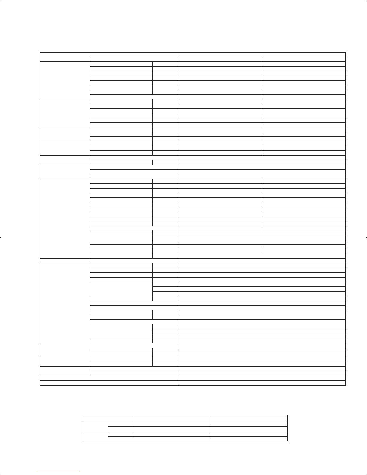
INDOOR UNIT
PLA-A12BA PLA-A18BA PLA-A24BA PLA-A30BA PLA-A36BA PLA-A42BA
3
OUTLINES AND DIMENSIONS
Unit: inch (mm)
14-27/3211-3/16
2-3/8
+5
0
(7.5)
(160)
(500)
(950)
Floor
Min.94-1/2(2400)
from floor
Entire
periphery
(36)
(83)
(83)
(36)
(500)
(950)
(597)
(597)
( 158)
(
[
175)
(350)
(
[
150)
(
14-[2.8
)
(167)
(155)
(130)
(100)
(90)
(90)
(100)
(100)
(35)
(17 )
+3/16
0
(190)
(156)
(105)
(50~70)
(140)
(170)
(377)
(284)
(60)
(24)
(187.5)
(840)
(160)
(160)
(20~45)
to 1-25/32
(860~910)
(620)
(605 )
-
3/16
+1-3/8
-
5
+35
(90)
(150)
(160)
(7.5)
(20
~45)
1-25/32
Corner pocket
In case of wireless remote controller
In case of standard grille
Drain hole
Drain pump clean hole
and Drain emergency
drainage hole
For MA-Remote controller
terminal block
Emergency operation switch<Cooling>
Emergency operation
switch<Heating>
Indoor unit
Ceiling
Cut out hole
Burring hole pitch
3-[1/8(3-[2.8)
Burring hole
Detail drawing of fresh air intake hole
Burring hole
14-[1/8
Cut out hole
Burring hole pitch
Cut out hole
Detail connecting of branch duct(Both aspects)
(77)
3-1/32
(85)
3-11/32
(298)
11- 3/4
11-1/16
(281)
(74)(80)(258)(241)
2-29/32
3-5/32
10-3/16
PLA-A36BA
PLA-A42BA
PLA-A24BA
PLA-A30BA
9-1/2
DCBA
2
Refrigerant pipe
····
[
15.88mm
Flared connection
····5/8
Refrigerant pipe
····
[
12.7mm
Flared connection
····1/2
1
Refrigerant pipe
····
[
6.35mm
Flared connection
····1/4
Refrigerant pipe
····
[
9.52mm
Flared connection
····3/8
Models
PLA-A12BA
PLA-A18BA
Min.19-11/16(500)
Grille
Ceiling
Suspension bolt
lower edge
Vane motor
Air intake grille
Air outlet hole
Air outlet hole
Auto vane
(Air outlet)
Air intake hole
Air intake hole
Grille
Ceiling
Keep 25/64(10)to 19/32(15)
between unit ceiling
and ceiling slab.
)(
Connected the attached
flexible pipe or socket.
Drain pipe
connected to VP-25
Suspension bolt
M10 or W3/8
Branch duct hole
Fresh air
intake hole
Branch duct
hole
Ceiling hole
Suspension bolt pitch
Suspension bolt pitch
Ceiling hole
(5/16)(5/16)
23-13/16
24-13/32
DEFROST/STAND BY lamp
Receiver
Operation lamp
For wiring replacement kit
terminal block
6-5/16
6-5/16
1
2
3-15/16
5-1/8
13-25/32
3-17/32
3-15/16
3-15/16
3-17/32
6-9/16
6-3/32
[
5-29/32
[
6-7/8
19-11/16
19-11/16
23-1/2
M
M
M
M
3-17/64
1-27/64
37-3/8
3-17/64
1-27/64
37-3/8
23-1/2
1-15/16~2-3/4
5-1/2
6-11/16
1-3/8
11/ 16
4-1/8
6-9/64
7-15/32
A
B
6-5/16
33-1/16(840)
5-29/32
3-17/32
C
D
33-1/16
7-3/8
25/32 to 1-25/32(20~45)
25/32 to 1-25/32(20~45)
33-27/32 to 35-13/16(860~910)
31-7/8(810)
25/32 to
33-27/32 to 35-13/1625/32
15/16
6-5/16
Indoor unit/Outdoor unit
connecting terminal block
[
4-29/32([125)
[
3-15/16([100)
6-7/32
120°
120°
ww
w
ww
w
w
w
w
w
Note1. As for drain pipe, please use VP-25(O.D.1-1/4(32mm) PVC TUBE).
Drain pump is included.
Max. lifting height is 33-7/16(850mm) from the ceiling.
2. As for suspension bolt, please use M10 or W3/8.
(Procured at local site)
3. Electrical box may be removed for the service purpose.
Make sure to slack the electrical wire little bit for
control/power wires connection.
4. The height of the indoor unit can be adjusted
with the grille attached.
5. For the installation of the optional high efficiency filter
or optional multi-functional casement.
1) Add 5-5/16(135mm) to the dimensions w marked on the figure.
2) Optional high efficiency filter must be used jointly with optional
multi-functional casement.
6. When installing the branch ducts, be sure to insulate adequately.
Otherwise condensation and dripping may occur.
(It becomes the cause of dew drops/water dew.)
7. As for necessary installation/service space, please refer to the
left figure.
16
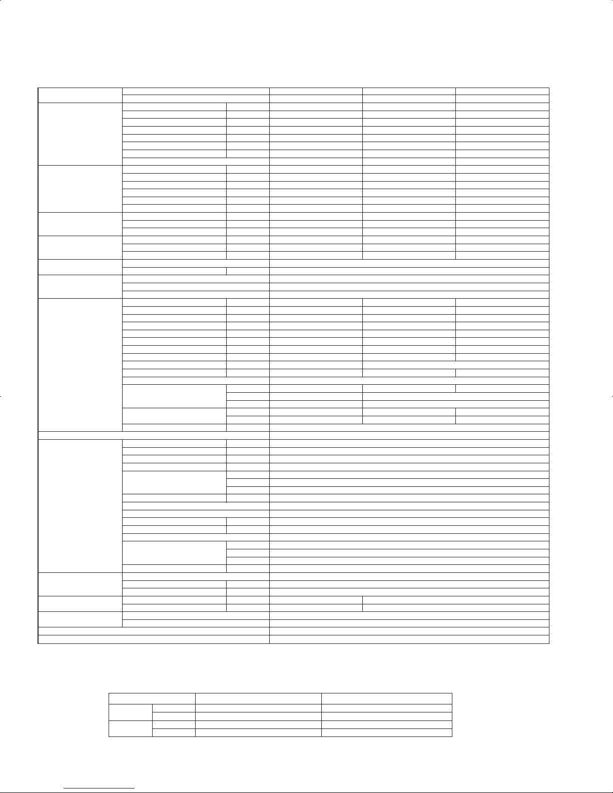
PKA-A12HA PKA-A12HAL PKA-A18HA PKA-A18HAL Unit: inch (mm)
1/2F ([12.7)
1/4F ([6.35)
Refrigerant
Piping
Drain hose
Gas pipe
Liquid pipe
[2-1/2~[3-1/8
([65~[80)
[2-1/2~[3-1/8
([65~[80)
Through hole
Sleeve
(purchased locally)
Center measurement hole [3/32([2.5)
5/32(3.8)
2-1/4(58)
0
Wall hole
for
left rear
piping
Knockout hole for
rear piping
2-3/4×12-3/16(70×310)
Wall hole for
right rear piping
77-
[
3/16([5.1)
Tapping
screw hole
4-[5/16([9)
Bolt hole
Mount board
Indoor unit outline
0
5/8(16)
9-15/16(253.5)
9-1/8(232.5)
1-1/16(28.5)
1-9/16(41)
3-1/16(78.5)
4-1/16(103.5)
4-9/16(116)
6-1/2(166)
7(178.5)
8(203.5)
3-9/16(91)
13/16(21.8)
9-1/16(231.5)
10-3/4(273.2)
0
1-1/4(32.7)
2-9/16(66)
2-1/16(53.5)
5(128.5)
6(153.5)
3/4(20)
9/16(15)
14-5/8(372.3)
14(356.3)
12-7/8(237.5)
11-7/16(291.5)
10-3/8(265)
9-5/16(238)
8-13/16(225)
7-13/16(200)
4-7/8(125)
2-3/4(70)
9/16(15)
14-5/8(372.3)
14(356.3)
12-7/8(327.5)
10-3/8(265)
11-7/16(291.5)
7-13/16(200)
8-13/16(225)
4-7/8(125)
2-3/4(70)
0
17-5/8(449)
7-9/16(193.5)
7-1/16(180.3)
6-9/16(167)
5-1/2(140)
4-1/2(115)
6-13/16(174)
8-3/8(213)
9-5/16(238)
10-15/16(278.3)
15-1/2(394)
11-1/16(281)
17-5/8(449)
0
Emergency operation switch
(cooling/heating)
Terminal block for
MA-remote controller
(only PKA-A·HA models)
Terminal block for power supply (option)
Front side(Grille open)
Terminal block for indoor/outdoor
connecting line
17-15/16(457)Gas pipe
21-3/16(539)Liquid pipe
6-5/8(169)
6-3/16(158)
24(610)Drain hose
7-3/16(184)
250mm,9-13/16inch or greater with
optional drain pump installation.
Required space(Indoor unit)
(mm)
Air inlet
Air inlet
Air outlet
Min.1-31/32(50)
Min.9-13/16(250)
Min.5-7/8(150)
Min.8-5/8
(220)
Min.1-31/32(50)
Min.1/4(7)
Knockout hole for piping
D
2-3/16(56)
2-11/16(69)
3/16(6)
1-11/16(43)
C
2-3/16(56)7/16(12.5)
1-11/16(43)
B
1-3/4(46)
2-5/16(60)
2-5/16(59)
1-11/16(43)
A
1-11/16(43)
1-3/4(46)
2-3/16(56)
3/16(6)
A
Knock out hole
for right piping
Right side
Mount board
3/16(5)
9-13/16(249)
Top side
15-3/16(387)
7-1/2(192)
7-3/4(197)
23-9/16(599)
C
B
Operation lamp
DEFROST/STAND BY lamp
Receiver
Louver(manual)
Vane(auto)
Knock out hole
for lower piping
Knock out hole
for lower piping
Under side
5/16(8)
24-1/16(612)
D
Knockout hole
for left piping
Left side
Front side
6-1/16(155)
2-1/8
(55)
27-1/16(688)
11-5/8(295)
35-3/8(898)
[
5/8 ([16) O.D
17
PKA-A24KA PKA-A24KAL PKA-A30KA PKA-A30KAL Unit: inch (mm)
PKA-A36KA PKA-A36KAL
Front side
46-1/16(1170)
9-1/2(241)
33-21/32(855)
2-29/32(74)
14-3/8(365)
Emergency operation switch
(cooling/heating)
Terminal block for Outdoor unit
Terminal block for
MA-remote controller (only PKA-A·KA models)
Front side(Grille open)
Terminal block for power supply (option)
Filter hook
6-1/16(154)
4-27/32(123)
18-31/32(482)Liquid pipe
17-15/32(444)Gas pipe
23-1/32(585)Drain hose
5-9/32(134)
Min.9/32(7)
Center measurement hole
[3/32([2.5)
Knockout hole for
rear piping
2-15/16×18-29/32(75×480)
75-[3/16([5.1)
Tapping
screw hole
Mount board
Wall hole for
right rear piping
Indoor unit outline
4-[11/32([9) Bolt hole
Wall hole for
left rear piping
1/8(3)
R
1-15/32(R37.5)
2-1/8(54)
0
5/8(15.5)
0
17-9/32(439)
0
17-9/32(439)
15-1/8(384)
13/32(10)
20-3/8(517.4)
17-7/8(454)
16-3/32(408.5)
15-1/8(384)
14-11/32(364)
12-3/8(314)
4-11/32(110)
2-3/8(60)
13/32(10)
18-5/16(465.5)
17-7/8(454)
16-3/32(408.5)
15-1/8(384.5)
14-11/32(364)
12-3/8(314)
4-11/32(110)
2-3/8(60)
1-1/4(32)
12-5/32(308.5)
31/32(25)
11-1/2(292)
11(279.5)
9-17/32(242)
7-9/16(192)
5-19/32(142)
4-29/32(125)
4-19/32(117)
3-15/16(100)
2-15/16(75)
1-31/32(50)
15-1/8(384)
0
13-3/4(349.2)
16-15/16(430.5)
1/2(12.5)
11-1/2(292)
10-13/32(264)
9-1/32(229.5)
8-17/32(217)
6-9/16(167)
5-3/32(129.5)
4-1/8(104.5)
3-7/16(87.5)
2-15/32(62.5)
1-15/32(37.5)
1/2(12.5)
2-1/8(54)
31/32(25)
0
12-1/4(311)
8-17/32(216.5)
13-11/32(339)
20-7/8(530.5)
7-7/16(189)
13-11/32(339)
17-11/16(449.2)
23-1/32(585)
23-1/32(585)
A
5/16(7.8)
3-1/32(77)
2-5/8(67)
2-9/16(65)
B
Knockout hole for piping
13/32(10.7)
2-9/16(65)
3-1/32(77)
3-7/16(87)
C
5/16(7.8)
2-9/16(65)
3-1/32(77)
2-5/8(67)
Louver(manual)
Vane(auto)
Knock out hole
for lower piping
Under side
BB
Receiver
DEFROST/STAND BY lamp
Operation lamp
2-19/32(66)
23/32(18)
1-1/4(32)
2-3/32(53)
1-3/16(30)
1-3/8(35)
Mount board
C
Knock out hole
for right piping
Right side
11-5/8(295)
3/16(5)
Left side
A
Knockout hole
for left piping
Top side
2-9/16(65.2)
5-17/132(140.3)
7/16(11)
17(431.7)
16-11/16(423.7)
Air outlet
Air inlet
Min.1-7/8(48)
Min.9-27/32(250)
Required space(Indoor unit)
Min.2(50.5)Min.8-21/32(220)
Min.2-27/32(72.4)
3
2
1
Refrigerant pipe: 3/8 O.D([9.52)
Refrigerant pipe: 5/8 O.D([15.88)
5/8([16) O.D
3 Drain hose
Piping connection department
1 Liquid pipe
2 Gas pipe
Through hole
[2-15/16
([75)
[2-15/16~[3-5/32
([75~[80)
Sleeve
(purchased locally)
Flared connection: 5/8F
Flared connection: 3/8F
18
PCA-A24KA PCA-A30KA Unit: inch (mm)
When drain socket
is installed
9-3/16(233)
Drainage
When drain socket
is installed
9-11/16(246)
i-see sensor
14
liquid Φ3/8(Φ9.52)
gas Φ5/8(Φ15.88)
Drainage
46-3/16(1173)
1/16(2) 1/16(2)50-3/8(1280)
1-7/8(48)5/16(8)
47-3/16(1198)
3-3/8(85)
7-3/16(182)
26-3/4(680)
18-3/4(476)
2-1/4(57)
9-1/16(230)
7-11/16(195)
3-7/16(88)
3-5/16(84)
3-1/8(80)
26-3/4(680)
12-5/8(320)
48-11/16(1237) (Suspension bolt pitch)
11/16(18)
5-1/2(140)
2-7/16(62)
5-7/8(150)
9-5/16(236)
7-7/8(200)
9-11/16(246)
2(51)
3/8(10)
3/16(5)
15-1/4(387)
3-3/8(86)
3-3/8(85)
4
1
7
1-1/2(38)
2
2-15/16(75)
When electrical box
is pulled down
1/16(2)
10-1/4(260)
1/16(1)
7-1/12(190)
1-7/16(37)
5-7/16(138)
4-15/16(126)
In case of the rear pipe arrangement, make sure to
remove the shaded portions from the independent piece.
Then put the independent piece back in initial
position.(The heat exchanger might be clogged because of dust)
8
Ceiling
Electrical box
3
5
[FRONT VIEW]
11/16(18)
4-3/4(121)
Φ4-
1
5/1
6(Φ125)
7-1/2(190)
3(76)
4-7/8(124)
18-1/8(461)
1-13/16(46)
6
9-3/16(233)
2
NOTES.
1.Use M10 or W3/8 screw for anchor bolt.
2.Please be sure when installing the drain lift up
mechanism(option parts),refrigerant pipe will be only upward.
DEFROST/STAND BY lamp
Emergency operation
switch <Cooling>
Receiver
Operation lamp
Emergency operation
switch <Heating>
In case of wireless remote controller
and i-see sensor(Optional Parts)
Knockout hole for upper drain pipe arrangement
Knockout hole for fresh air intake Φ3-15/16(Φ100)
Knockout hole for wiring arrangement Φ7/8(Φ22)
Accessory...Drain socket (1(26mm) I.D.)
8
7
6
3
214
5
Drainage pipe connection(1(26mm)I.D.)
Drainage pipe connection(for the left arrangement)
Knockout hole for left drain-piping arrangement
Refrigerant-pipe connection(gas pipe side/flared connection)
Refrigerant-pipe connection(liquid pipe side/flared connection)
Electrical box
Air outlet
In case of wireless
remote controller
and i-see sensor
(Optional Parts)
9/16
10(254)
7-1/16(180)
7
120°
8
Air intake

19
PCA-A36KA PCA-A42KA Unit: inch (mm)
When drain socket
is installed
9-3/16(233)
When drain socket
is installed
Drainage
9-11/16(246)
14
NOTES.
1.Use M10 or W3/8 screw for anchor bolt.
2.Please be sure when installing the drain lift up
mechanism (option parts),refrigerant pipe will be only upward.
6
80
26-3/4(680)
12-5/8(320)
61-5/16(1557) (Suspension bolt pitch)
11/16(18)
140
62
5-7/8(150)
2-7/165-1/2
3-1/8
Air outlet
58-3/4(1493)
1/16(2) 63(1600)
9-1/16(230)
7-11/16(195)
3-7/16(88)
3-5/16(84)
[FRONT VIEW]
5
1
1-7/8(48)5/16(8)
9-3/16(233)
1-13/16(46)
18-1/8(461)
4-7/8(124)
3(76)
7-1/2(190)
Φ
4-15/16(Φ125)
4-3/4(121)
11/16(18)
3
Electrical box
Ceiling
8
In case of the rear pipe arrangement, make sure to
remove the shaded portions from the independent piece.
Then put the independent piece back in initial
position.(The heat exchanger might be clogged because of dust)
4-15/16(126)
5-7/16(138)
1-7/16(37)
7-1/2(190)
1/16(1)
10-1/4(260)
1/16(2)
When electrical box
is pulled down
2-15/16(75)
2
1-1/2(38)
7
4
3-3/8(85)
3-3/8(86)
15-1/4(387)
2
Electrical box
Air intake
59-3/4(1518)
26-3/4(680)
18-3/4(476)
57
182
85
7-3/16 3-3/8
2-1/4
In case of wireless remote controller
and i-see sensor(Optional Parts)
Emergency operation
switch <Heating>
Operation lamp
Receiver
Emergency operation
switch <Cooling>
DEFROST/STAND BY lamp
9-5/16(236)
liquid Φ3/8(Φ9.52)
gas Φ5/8(Φ15.88)
Drainage
7-7/8(200)
9-11/16(246)
2(51)
3/8(10)
3/16(5)
9/16
In case of wireless
remote controller
and i-see sensor
(Optional Parts)
1/16(2)
1
120°
2-15/16(75)
10(254)
7-1/16(180)
Knockout hole for upper drain pipe arrangement
Knockout hole for fresh air intake Φ3-15/16(Φ100)
Knockout hole for wiring arrangement Φ7/8(Φ22)
Accessory...Drain socket (1(26mm)I.D.)
Drainage pipe connection(1(26mm)I.D.)
Drainage pipe connection(for the left arrangement)
Knockout hole for left drain-piping arrangement
Refrigerant-pipe connection
(gas pipe side/flared connection)
Refrigerant-pipe connection
(liquid pipe side/flared connection)
8
7
6
5
4
3
2
11

20
PEA-A12AA PEA-A18AA Unit: mm (inch)
(46-7/8)
1190
(39)
990
N
(48-25/32)
1239
(40-29/32)
1039
M
ø12.7(1/2)
mm(in.)
(35-7/16)
(27-9/16)
(41-3/4)
(33-7/8)
(47-1/4)
(39-3/8)
(39-3/8)
(31-1/2)
(41-3/4)
(33-7/8)
(47-3/16)
(39-5/16)
(45-3/8)
(37-1/2)
(43-5/16)
(35-7/16)
ø6.35(1/4)
900 952 998 860
9
800 1000 860
7
700
20
24
L
900
K
9
J
1060
HG
1200
F
1000
E
11
D
1060
C
1100B1152
PEA-A12AA
PEA-A18AA
Model A
1198
Gas pipe Liquid pipe
1
2
Note1.Use M10 screw for the suspension bolt (field supply).
2.Keep the service space for the maintenance at the bottom.
3.This chart indicates for PEA-A12AA model,which has 2 fans.
PEA-A18AA models have 4 fans.
4.In case an inlet duct is used,remove the air filter(supply with
the unit), then install the filter(field supply) at suction side.
Drain pipe(O.D.ø32(1-1/4))
Terminal block (Remote controller transmission line)
Terminal block (Indoor/outdoor connecting line)
2
Refrigerant piping
flare connection (liquid)
Drain pipe(O.D.ø32(1-1/4))
(Emergency draining)
Knockout hole ø27(1-3/32)
(Remote controller transmission line)
Knockout hole
ø
27(1-3/32)
(Indoor/outdoor connecting line)
L-ø2.9(1/8)
2X2-ø2.9(1/8)
2XE-ø2.9(1/8)
Control box
Air filter
Suspension bolt hole
4-14X30(9/16X1-3/16) Slot
Refrigerant piping
flare connection (gas)
1
Drain pipe(O.D.ø32(1-1/4))
(Spontaneous draining)
Air
inlet
Air
outlet
N
M
57(2-1/4)
57(2-1/4)
159(6-9/32)
345(13-19/32)
(3-9/16)
(5-29/32)
(2-25/32)(4-19/32)
70
10 (13/32)
(3-15/16)
(1-15/16) (24-5/8)
37(1-15/32)
200(7-7/8)
H
20(13/16)
157.5 (6-7/32)
20 (13/16)
100 (3-15/16)
37(1-15/32)
12(1/2)
12(1/2)
88(3-15/32)
100(3-15/16)XJ=K
100(3-15/16)
88(3-15/32)
10 (13/32)
49
25(1)
170(6-23/32)
102(4-1/32)
270(10-21/32)
116
150(Duct)
23(29/32)
100
25(1)
700(27-9/16)
677(26-21/32)
23 (29/32)
C
B (Suspension bolt pitch)23(29/32)
A
90
625 (Suspension bolt pitch)
D (Duct)
30(1-3/16)
100(3-15/16)X(E-1)=F
100(3-15/16)
20(13/16)
15(19/32)
(1-31/32 ~ 5-29/32)
(30-19/32)
(17-23/32)
(11-13/16)
(17-23/32)
More than 300
450
777
50
(1-31/32)
50 ~ 150
50(1-31/32)
G
450
Note2
Access door
Required space for service and maintenance
More than 20
More than 10
(13/16)
(13/32)
Access door
Ceiling surface
Make the access door at the appointed position
properly for service maintenance.
175±5(6-29/32±7/32)
Less than 300
Less than 550
(11-13/16)
(21-21/32)
Drain hose (I.D.ø32(1-1/4))
<accessory>
(Actual length)
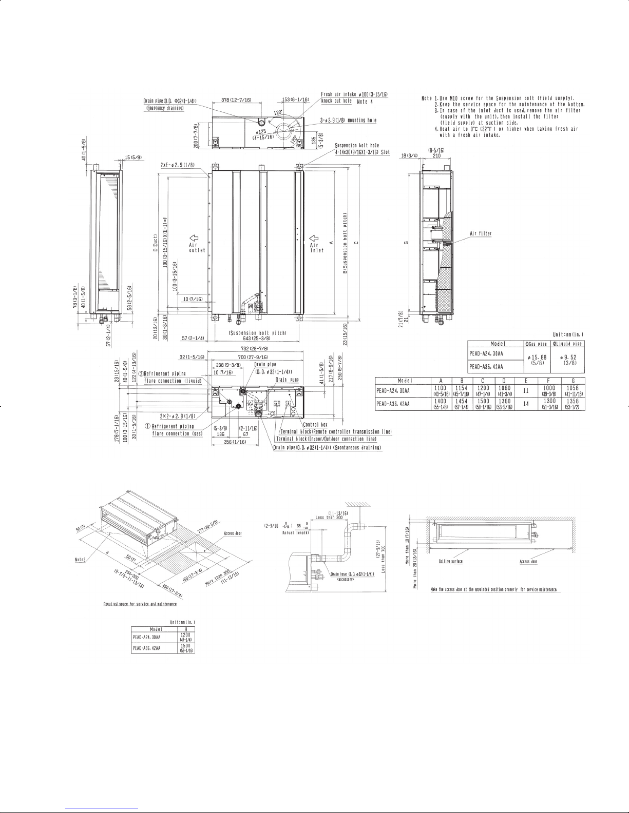
21
PEAD-A24AA PEAD-A30AA PEAD-A36AA PEAD-A42AA Unit: mm (inch)
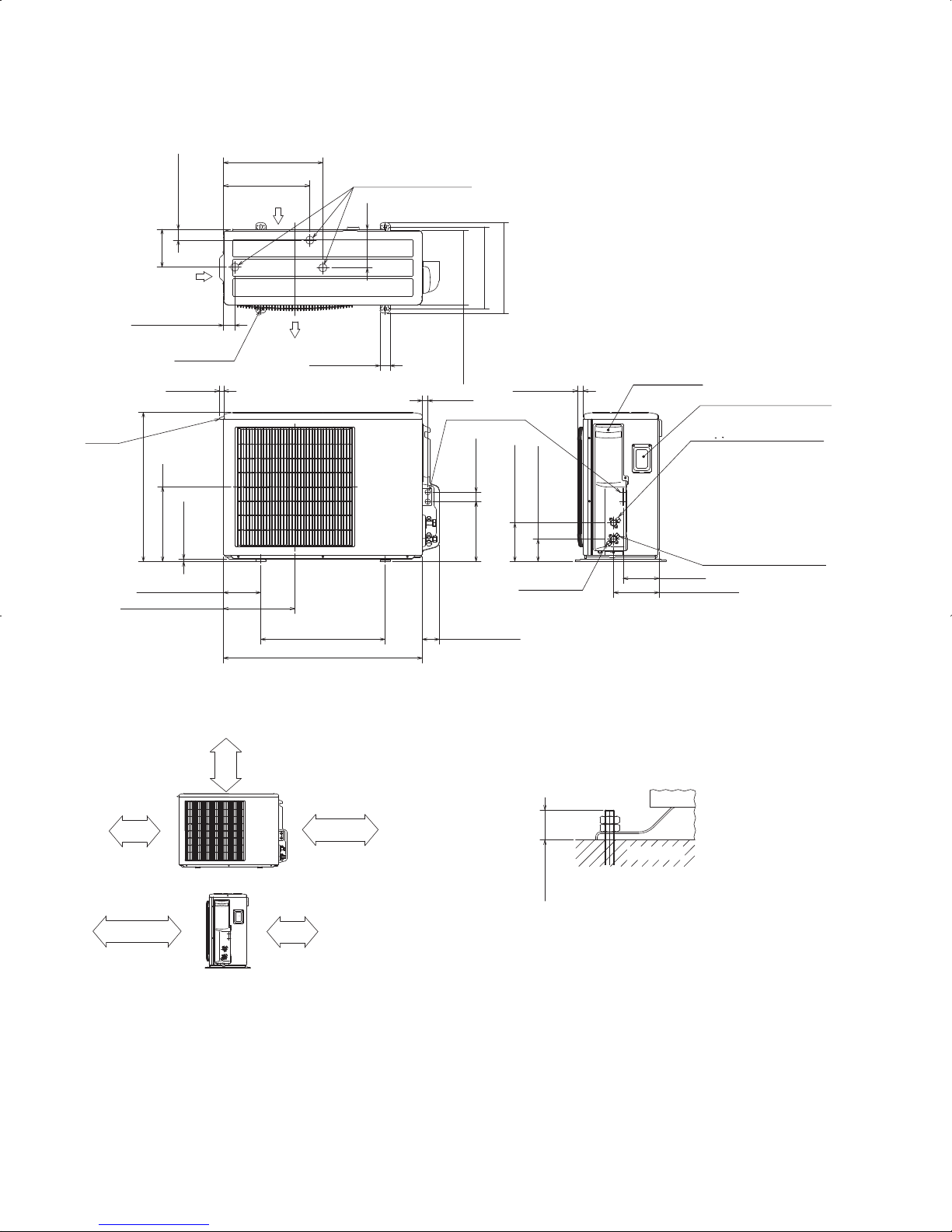
22
OUTDOOR UNIT Unit: mm (inch)
PUY-A12NHA3(-BS) PUY-A18NHA3(-BS) PUZ-A18NHA3(-BS)
1/2 conduit hole
144<5-21/32>
2-{22.2<7/8>
22<7/8>
38<1-1/2>241<9-1/2>
Min.100mm<3-15/16>
Piping and wiring connection can
be made from the rear direction only.
*1 In the place where short cycle tends to occur, cooling and heating capacity and power consumption might get lowered 10%.
Air outlet guide (optional PAC-SG58SG-E) will help them improve.
*2 If air discharges to the wall, the surface might get stained.
2 sides should be open in
the right, left and rear side.
Min.100mm<3-15/16> as long as
no obstacle is placed on the
rear and light-and-left sides
of the unit
*1
*2
*1
Air intake
Air discharge
4-oval hole
Air intake
Service panel
Connection for liquid pipe
Service panel for charge plug
Service port
Connection for gas pipe
Min.100mm<3-15/16>
Min.500mm<19-11/16>
Min.350mm<13-25/32>
Basically
open
Max.
<Foundation bolt height>
FOUNDATION
Please secure the unit firmly
with 4 foundation M10<W3/8> bolts.
(Bolts, washers and nut must
be purchased locally.)
18mm<23/32>
{33<1-5/16> drain hole
43.6<1-23/32>
152<6>
155
400<15-25/32>
347.5<13-11/16>
45.4<1-25/32>
365<14-3/8>
330<13>
300<11-13/16>
40<1-9/16>
Handle
600<23-5/8>
10<3/8>
300<11-13/16>
150<5-29/32>
287.5<11-11/32>
500<19-11/16>
800<31-1/2>
69<2-23/32>
183<7-7/32>
90<3-17/32>
155<6-3/32>
23<29/32>
32.5<1-9/32>
18<23/32>
FLARE {12.7<1/2>
FLARE {6.35<1/4>
Installation bolt pitch
PIPING-WIRING DIRECTION
Minimum installation space for outdoor unit
Free space around the outdoor unit
(basic example)
FOUNDATION BOLTS
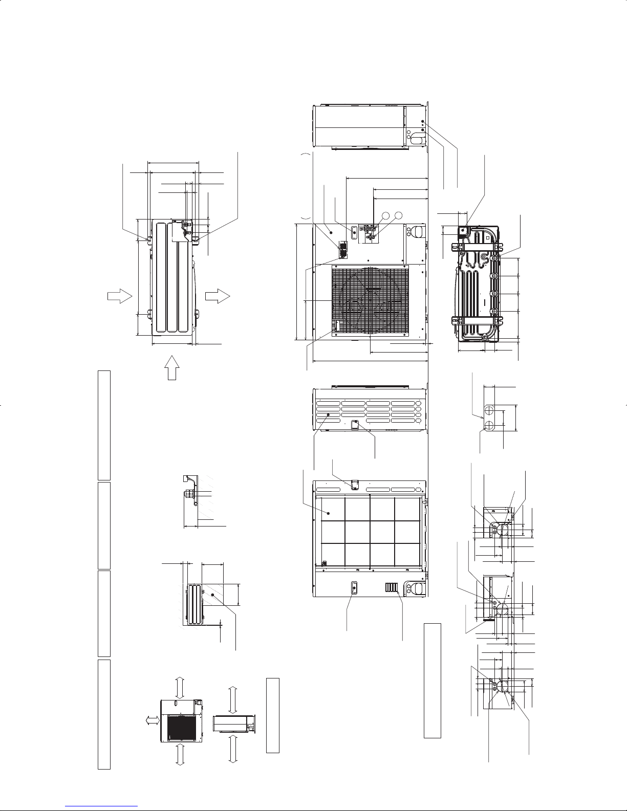
23
PUZ-A24NHA3(-BS) PUY-A24NHA3(-BS) Unit: mm (inch)
PUZ-A30NHA3(-BS) PUY-A30NHA3(-BS)
PUZ-A36NHA3(-BS) PUY-A36NHA3(-BS)
Min. 10mm
<3/8>
Min. 10mm
<3/8>
Min. 100mm
<3-15/16>
Min. 500mm
<19-11/16>
Min.
100mm
<3-15/16>
Min.
500mm
<191/16>
Max.
300mm<1-3/16>
Min.
10mm
<3/8>
Min.
500mm
<19-11/16>
Service space
FOUNDATION
<Foundation bolt height>
FREE
When installing the conduit,
Set the attachment to the
inner side of each panel.
1/2 Conduit attachment
2-[22.2<7/8>
40<1-9/16>
31<1-7/32>
74<2-19/32>
330 <13>
175 <6-7/8>
600 <23-5/8>
175 <6-7/8>
53 <2-3/32>
28 <1-3/32>
370 <14-9/16>
19 <3/4>
56 <2-7/32>
45 <1-25/32>
42 <1-21/32>
66 <2-5/8>
417 <16-13/32>
2-U Shaped notched hole
(Foundfation Bolt M10<W3/8>)
Side Air Intake
Rear Air Intake
Air Discharge
2-12o36 Oval hole
(Foundation Bolt M10<W3/8>)
30 <1-3/16>
Side Air Intake
Handle
Rear piping cover
Front piping cover
81<3-3/16>
219 <8-5/8>
30 <1-3/16>
71 <2-13/16>
71 <2-13/16>
Bottom piping hole
(Knockout)
Drain hole
(5-[33<1-5/16>)
Handle
Handle
Rear Air Intake
Air Intake
670 <26-3/8>
*1 443<17-7/16>
*1 447<17-19/32>
322 <12-11/16>
950 <37-13/32>
473 <18-5/8>
943 <37-1/8>
23<29/32>
2
1
Handle
Handle
Service panel
Earth terminal
Left···Power supply wiring
Reight···Indoor/Outdoor wiring
Terminal Block
Conduit hole
(2-
[
27<1-1/16>Knockout)
Right trunking hole
(Knockout)
Right piping hole
(Knockout)
65<2-9/16>
92<3-5/8>
40 <1-9/16> 45 <1-25/32>
19<3/4>
27<1-1/16>
23<29/32>
23<29/32>
73<2-7/8>
Conduit hole
(2-[27<1-1/16>Knockout)
Front trunking hole
(Knockout)
Front piping hole
(Knockout)
[9
2
<3-5/8>
Conduit hole
(2-
[
27<1-1/16>Knockout)
Rear trunking hole
(Knockout)
Rear piping hole
(Knockout)
220
<8-21/32>
145
<5-23/32>
145
<5-23/32>
145
<5-23/32>
55<2-3/16>
63<2-1/2>
63<2-1/2>
75
<2-31/32>
40<1-9/16>
45<1-25/32>
40<1-9/16>
23<29/32>
73<2-7/8>
63<2-1/2>
55<2-3/16>
27<1-1/16>
[92<3-5/8>
[
92<3
-
5
/8>
73<2-7/8>
27<1-1/16>
92<3-5/8>
92<3-5/8>
65<2-9/16>
95<3-5/8>
55<2-3/16>
Piping and wiring connections
can be made from 4 directions:
front, right, rear and below.
Dimensions of space needed
for service access are
shown in the below diagram.
Please secure the unit firmly
with 4 foundation (M10<W3/8>)
bolts. (Bolts and washers must
be purchased locally.)
The diagram below shows a
basic example.
Explantion of particular details are
given in the installation manuals etc.
1····Refrigerant GAS pipe connction (FLARE)[15.88<5/8>
2····Refrigerant LIQUID pipe connection (FLARE)[ 9.52<3/8>
*1 ····Indication of STOP VALVE connection location.
Example of Notes
Piping Knockout Hole Details
1 FREE SPACE (Around the unit)
2 SERVICE SPACE
3 FOUNDATION BOLTS
4 PIPING-WIRING DIRECTIONS
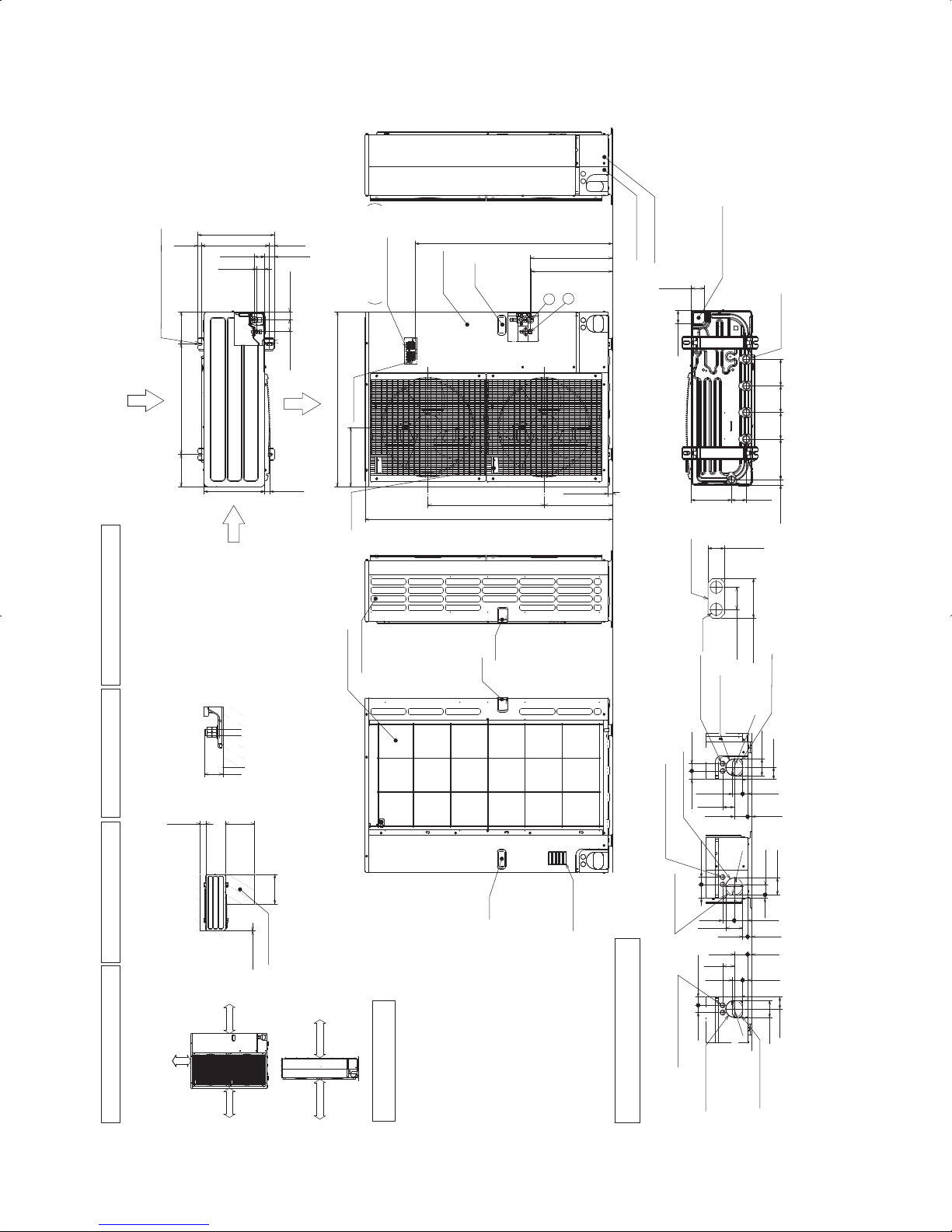
24
PUZ-A42NHA3(-BS) Unit: mm (inch)
PUY-A42NHA3(-BS)
Min. 1000mm
<39-3/8>
Min. 150mm
<5-29/32>
Min. 10mm
<3/8>
Min. 10mm
<3/8>
FREE
<Foundation bolt height>
FOUNDATION
Service space
Terminal Block
Left···Power supply wiring
Right····Indoor/Outdoor wiring
Earth terminal
Service panel
Handle
1
2
23<29/32>
1076<42-3/8>
* 1 447<17-19/32>
* 1 443<17-7/16>
Handle
Front piping cover
Rear piping cover
Air Discharge
Rear Air Intake
Side Air Intake
31<1-7/32>
145
<5-23/32>
145
<5-23/32>
220
<8-21/32>
30<1-3/16>
145
<5-23/32>
81<3-3/16>
219<8-5/8>
71<2-13/16>
71<2-13/16>
Bottom piping hole
(Knockout)
Drain hole
5-[33<1-5/16>
Handle
Side Air Intake
Air intake
Rear Air Intake
Handle
Handle
40<1-9/16>
74<2-19/32>
When installing the conduit.
Set the attachment to the
inner side of each panel.
2-[22.2<7/8>
1/2 Conduit attachment
45<1-25/32>
40<1-9/16>
65<2-9/16>
92<3-5/8>
27<1-1/16>
55<2-3/16>
23<29/32>
73<2-7/8>
63<2-1/2>
Rear piping hole
(Knockout)
Rear trunking hole
(Knockout)
Conduit hole
(2-[27<1-1/16>Knockout)
[9
2
<3-5/8>
19<3/4>
55<2-3/16>
92<3-5/8>
75
<2-31/32>
40<1-9/16>
73<2-7/8>
63<2-1/2>
23<29/32>
27<1-1/16>
92<3-5/8>
Right piping hole
(Knockout)
Right trunking hole
(Knockout)
Conduit hole
(2-[27<1-1/16>Knockout)
[92
<3-5
/8
>
92<3-5/8>
65<2-9/16>
45<1-25/32>
40<1-9/16>
27<1-1/16>
55<2-3/16>
23<29/32>
73<2-7/8>
63
<2-1/2>
Front piping hole
(Knockout)
Front trunking hole
(Knockout)
Conduit hole
(2-[27<1-1/16>Knockout)
[92
<3-5/8>
371<14-19/32>
330<13>30<1-3/16>
175<6-7/8>
600<23-5/8>
175<6-7/8>
42<1-21/32>
66<2-5/8>
950<37-13/32>
322<12-11/16>
1350<53-5/32>
635<25>
19<3/4>
417<16-13/32>
370<14-9/16>
2-U Shaped notched hole
(Foundation Bolt M10<W3/8>)
56<2-7/32>
28<1-3/32>
53<2-3/32>
45<1-25/32>
2-12o36 Oval hole
(Foundation Bolt M10<W3/8>)
1
····Refrigerant GAS pipe connction (FLARE)[15.88<5/8>
2
····Refrigerant LIQUID pipe connection (FLARE)[ 9.52<3/8>
*1 ····Indication of STOP VALVE connection location.
Example of Notes
1 FREE SPACE (Around the unit)
2 SERVICE SPACE
3 FOUNDATION BOLTS
4 PIPING-WIRING DIRECTIONS
Piping Knockout Hole Details
The diagram below shows a
basic example.
Explantion of particular details are
given in the installation manuals etc.
Dimensions of space needed
for service access are
shown in the below diagram.
Please secure the unit firmly
with 4 foundation (M10<W3/8>)
bolts. (Bolts and washers must
be purchased locally.)
Piping and wiring connections
can be made from 4 directions:
front, right, rear and below.
Min.
10mm<3/8>
Min.
500mm
<19-11/16>
Min.
500mm
<19-11/16>
Min.
150mm
<5-29/32>
Min.
30mm
<1-3/16>
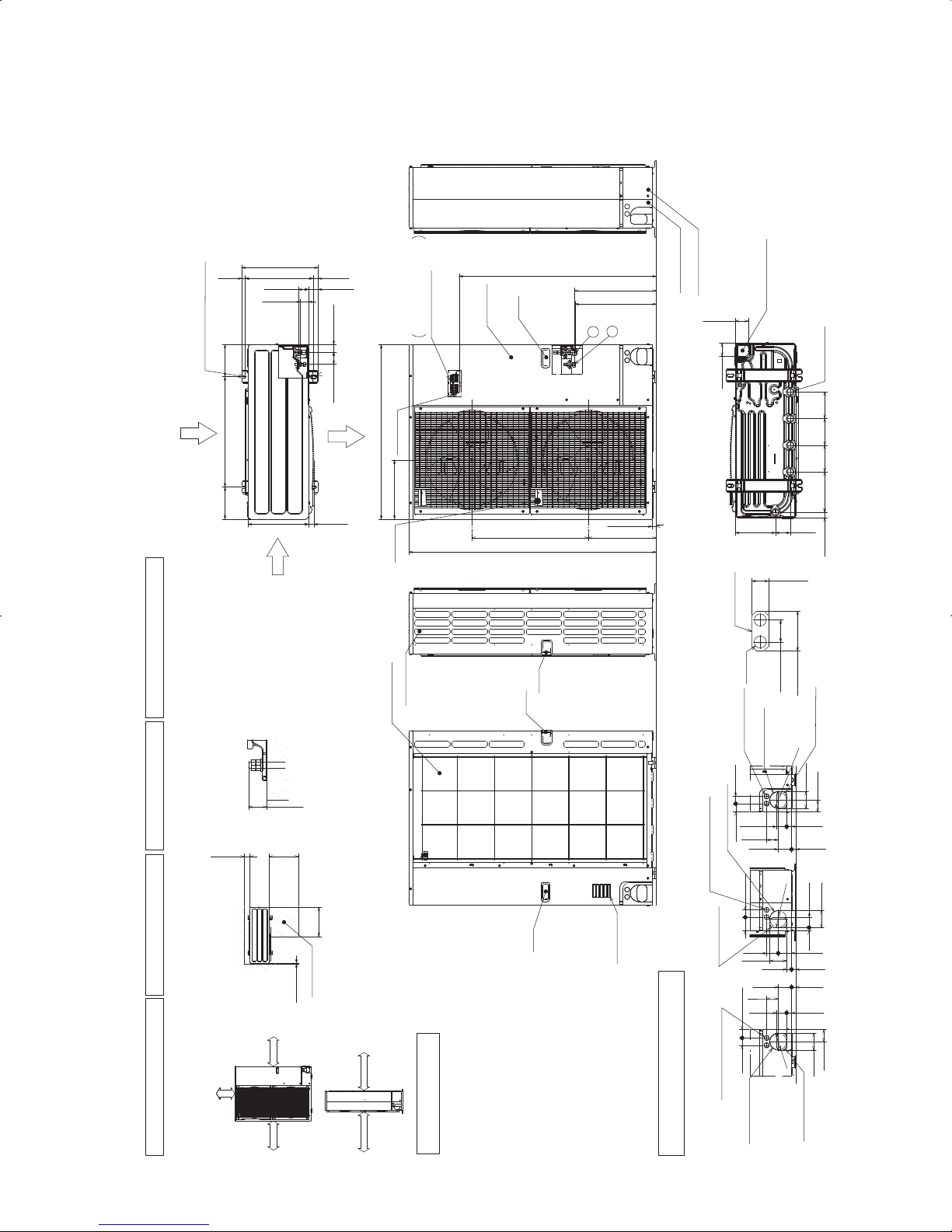
25
PUZ-HA30NHA2 PUZ-HA36NHA2 Unit: mm (inch)
Min. 1000mm
<39-3/8>
Min. 150mm
<5-29/32>
Min. 10mm
<3/8>
Min. 10mm
<3/8>
FREE
<Foundation bolt height>
FOUNDATION
Service space
Terminal Block
Left···Power supply wiring
Right····Indoor/Outdoor wiring
Earth terminal
Service panel
Handle
1
2
23<29/32>
1076<42-3/8>
* 1 447<17-19/32>
* 1 443<17-7/16>
Handle
Front piping cover
Rear piping cover
Air Discharge
Rear Air Intake
Side Air Intake
31<1-7/32>
145
<5-23/32>
145
<5-23/32>
220
<8-21/32>
30<1-3/16>
145
<5-23/32>
81<3-3/16>
219<8-5/8>
71<2-13/16>
71<2-13/16>
Bottom piping hole
(Knockout)
Drain hole
5-[33<1-5/16>
Handle
Side Air Intake
Air intake
Rear Air Intake
Handle
Handle
40<1-9/16>
74<2-19/32>
When installing the conduit.
Set the attachment to the
inner side of each panel.
2-[22.2<7/8>
1/2 Conduit attachment
45<1-25/32>
40<1-9/16>
65<2-9/16>
92<3-5/8>
27<1-1/16>
55<2-3/16>
23<29/32>
73<2-7/8>
63<2-1/2>
Rear piping hole
(Knockout)
Rear trunking hole
(Knockout)
Conduit hole
(2-[27<1-1/16>Knockout)
[
92
<
3-5/
8>
19<3/4>
55<2-3/16>
92<3-5/8>
75
<2-31/32>
40<1-9/16>
73<2-7/8>
63<2-1/2>
23<29/32>
27<1-1/16>
92<3-5/8>
Right piping hole
(Knockout)
Right trunking hole
(Knockout)
Conduit hole
(2-[27<1-1/16>Knockout)
[
92
<3-5
/8
>
92<3-5/8>
65<2-9/16>
45<1-25/32>
40<1-9/16>
27<1-1/16>
55<2-3/16>
23<29/32>
73<2-7/8>
63
<2-1/2>
Front piping hole
(Knockout)
Front trunking hole
(Knockout)
Conduit hole
(2-[27<1-1/16>Knockout)
[92
<3-5/8>
371<14-19/32>
330<13>30<1-3/16>
175<6-7/8>
600<23-5/8>
175<6-7/8>
42<1-21/32>66<2-5/8>
950<37-13/32>
322<12-11/16>
1350<53-5/32>
635<25>
19<3/4>
417<16-13/32>
370<14-9/16>
2-U Shaped notched hole
(Foundation Bolt M10<W3/8>)
56<2-7/32>
28<1-3/32>
53<2-3/32>
45<1-25/32>
2-12o36 Oval hole
(Foundation Bolt M10<W3/8>)
1····Refrigerant GAS pipe connction (FLARE)[15.88<5/8>
2····Refrigerant LIQUID pipe connection (FLARE)[ 9.52<3/8>
*1 ····Indication of STOP VALVE connection location.
Example of Notes
1 FREE SPACE (Around the unit)
2 SERVICE SPACE
3 FOUNDATION BOLTS
4 PIPING-WIRING DIRECTIONS
Piping Knockout Hole Details
The diagram below shows a
basic example.
Explantion of particular details are
given in the installation manuals etc.
Dimensions of space needed
for service access are
shown in the below diagram.
Please secure the unit firmly
with 4 foundation (M10<W3/8>)
bolts. (Bolts and washers must
be purchased locally.)
Piping and wiring connections
can be made from 4 directions:
front, right, rear and below.
Min.
10mm<3/8>
Min.
500mm
<19-11/16>
Min.
500mm
<19-11/16>
Min.
150mm
<5-29/32>
Min.
30mm
<1-3/16>
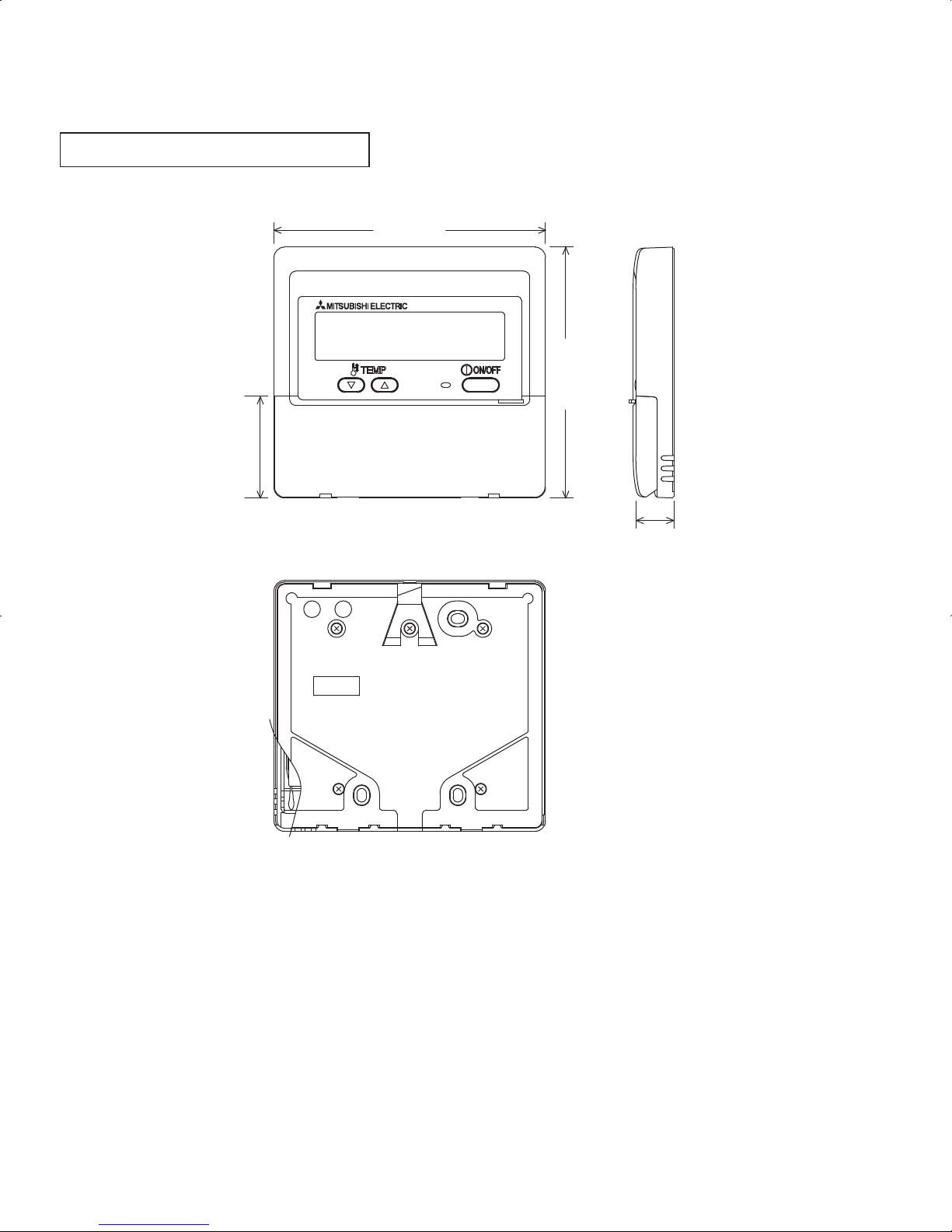
26
WIRED REMOTE CONTROLLER
130<5-1/8>
120<4-3/4>
19
<3/4>
48.5<1-15/16>
Unit: mm (inch)
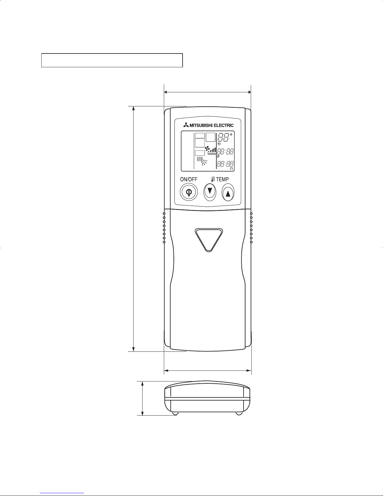
27
Unit: mm (inch)
WIRELESS REMOTE CONTROLLER
159.3<6-3/8>
55<2-5/32>
58<2-9/32>
19<3/4>
MODEL
SELECT
NOT AVAILABLE
SWING
CHECK
FAN
TEST
RUN
°F
°C
AMPMSTOP
START
AMPM
COOL
DRY
AUTO
FAN
HEAT
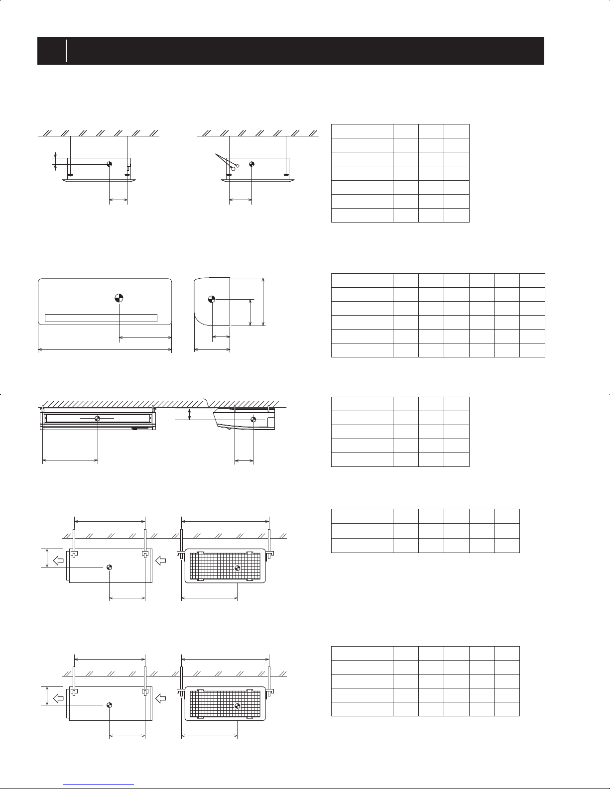
28
4
POSITION OF THE CENTER OF GRAVITY
4-1. INDOOR UNIT
Z
X
Y
Refrigerant pipe side
Refrigerant pipe
PLA-A·BA
Unit: inch (mm)
PCA-A·KA
Unit: inch (mm)
PKA-A·HA(L)
PKA-A·KA(L)
Unit: inch (mm)
X
D
Y
W
Z
H
Y
X
Z
PEA-A·AA
Unit: inch (mm)
YX
L
W
Z
PEAD-A·AA
Unit: inch (mm)
YX
L
W
Z
Model name X Y Z
PLA-A12BA
PLA-A18BA
PLA-A24BA
PLA-A30BA
PLA-A36BA
PLA-A42BA
11-1/32
(280)
15-3/4
(400)
4-5/32
(105)
4-5/32
(105)
4-5/32
(105)
4-5/32
(105)
4-15/16
(125)
4-15/16
(125)
15-3/4
(400)
15-3/4
(400)
15-3/4
(400)
15-3/4
(400)
15-3/4
(400)
11-1/32
(280)
11-1/32
(280)
11-1/32
(280)
11-1/32
(280)
11-1/32
(280)
35-3/8
(898)
35-3/8
(898)
46-1/8
(1170)
9-13/16
(249)
9-13/16
(249)
11-5/8
(295)
11-5/8
(295)
11-5/8
(295)
11-5/8
(295)
11-5/8
(295)
14-3/8
(365)
14-3/8
(365)
14-3/8
(365)
4-3/4
(120)
4-3/4
(120)
7-1/2
(190)
7-1/2
(190)
7-1/2
(190)
15-3/8
(390)
18-1/8
(460)
6-5/16
(160)
7-1/2
(190)
15-3/8
(390)
18-1/8
(460)
6-5/16
(160)
7-1/2
(190)
18-1/8
(460)
7-1/2
(190)
46-1/8
(1170)
46-1/8
(1170)
4-3/8
(110)
24-1/16
(610)
4-9/16
(115)
4-3/8
(110)
24-1/16
(610)
4-9/16
(115)
4-3/8
(110)
30-3/8
(770)
4-9/16
(115)
4-3/8
(110)
24-10/16
(625)
25-6/16
(643)
45-7/16
(1154)
12-13/16
(325)
20-11/16
(525)
20-11/16
(525)
26-10/16
(675)
26-10/16
(675)
12-13/16
(325)
13
(330)
13
(330)
25-6/16
(643)
45-7/16
(1154)
25-6/16
(643)
57-4/16
(1454)
25-6/16
(643)
57-4/16
(1454)
24-10/16
(625)
30-3/8
(770)
4-9/16
(115)
Model name X Y Z
PCA-A24KA
PCA-A30KA
PCA-A36KA
PCA-A42KA
Model name W L X
PEA-A12AA
PEA-A18AA
37-8/16
(952)
45-6/16
(1152)
11-5/16
(286)
11-4/16
(285)
Y
17-11/16
(448)
20-12/16
(527)
Z
4-2/16
(104)
4-2/16
(104)
Model name W L X
PEAD-A24AA
PEAD-A30AA
PEAD-A36AA
PEAD-A42AA
YZ
5-2/16
(130)
5-2/16
(130)
5-2/16
(130)
5-2/16
(130)
Model name W D H X Y Z
PKA-A12HA(L)
PKA-A18HA(L)
PKA-A24KA(L)
PKA-A30KA(L)
PKA-A36KA(L)
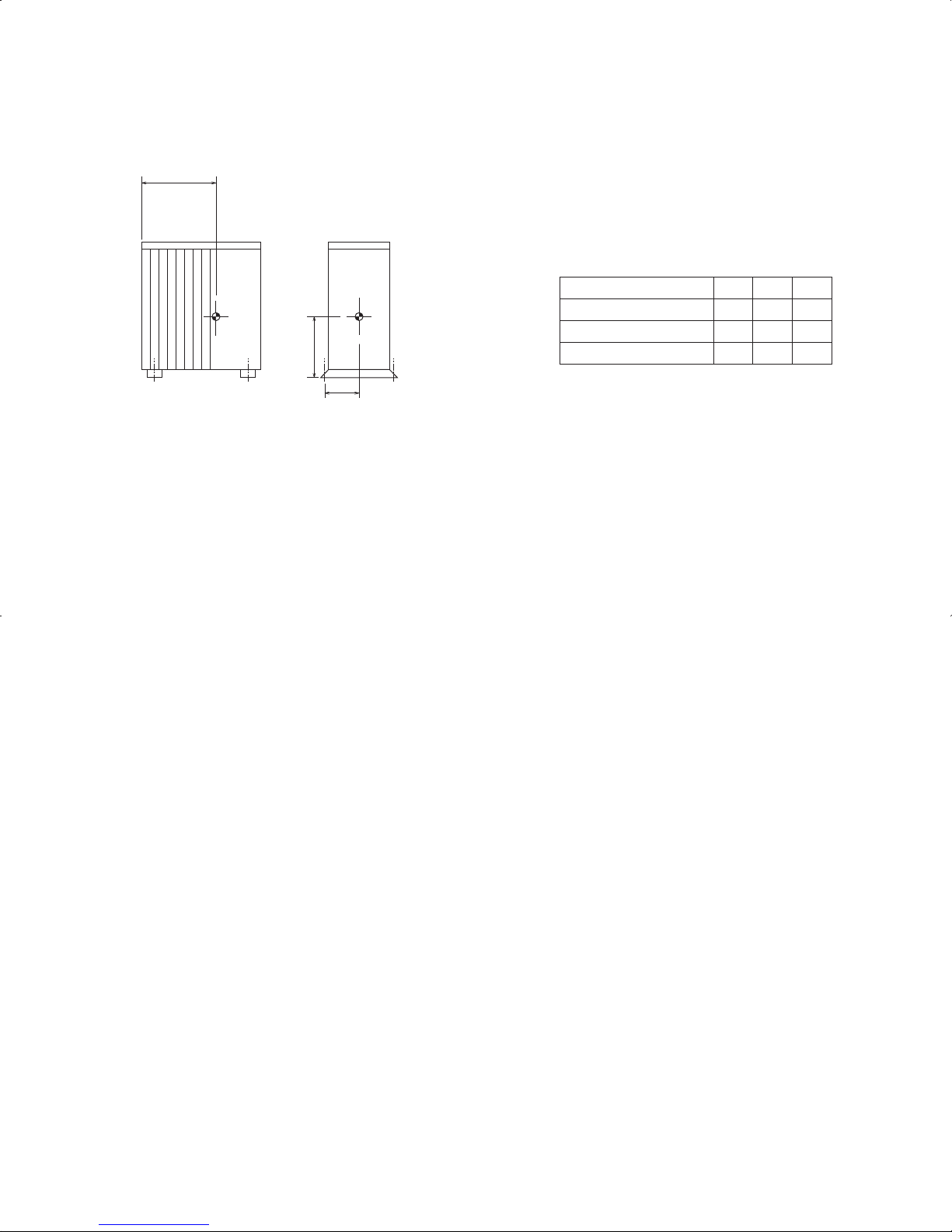
29
4-2. OUTDOOR UNIT
X
Unit: inch (mm)
Model name X Y Z
20-5/64
6-1/2
PUZ(Y)-A12/18NHA
PUZ(Y)-A24/30/36NHA
Z
PUZ(Y)-A42NHA
(510)
23-15/64
(590)
23-15/64
(590)
(165)
7-9/32
(185)
7-9/32
(185)
11-27/64
(290)
15-55/64
(403)
19-11/16
(500)
Y
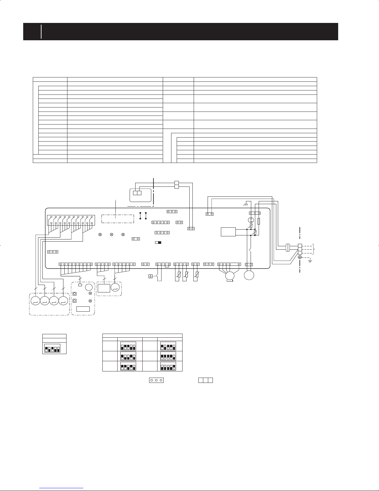
30
5
WIRING DIAGRAM
PLA-A12BA PLA-A18BA PLA-A24BA PLA-A30BA PLA-A36BA PLA-A42BA
<Table 2>SW2(CAPACITY CODE)
Service
PLA-A30BA
PLA-A36BA
PLA-A42BA
PLA-A12BA
PLA-A18BA
PLA-A24BA
MODELS
SW2
ON
OFF
12345
Service
MODELS
ON
OFF
12345
ON
OFF
12345
ON
OFF
12345
ON
OFF
12345
ON
OFF
12345
<Table 1>SW1(MODEL SELECTION)
Service
SW1
ON
OFF
12345
SYMBOL SYMBOLNAME NAME
I.B INDOOR CONTROLLER BOARD
FUSE (T6.3AL250V)
VAR IST OR
SURGE ABSORBER
CONNECTOR (LOSSNAY)
CONNECTOR (REMOTE SWITCH)
CONNECTOR (HA TERMINAL-A)
CONNECTOR (CENTRALLY CONTROL)
POWER SUPPLY (I.B)
POWER SUPPLY (R.B)
TRANSMISSION (INDOOR-OUTDOOR)
RELAY (DRAIN PUMP)
SWITCH (MODEL SELECTION) wSee table 1.
SWITCH (CAPACITY CODE) wSee table 2.
CONNECTOR (EMERGENCY OPERATION)
FAN MOTOR
VANE MOTOR
DRAIN-UP MACHINE
DRAIN FLOAT SWITCH
TERMINAL BLOCK (INDOOR/OUTDOOR CONNECTING LINE)
TERMINAL BLOCK (REMOTE CONTROLLER
TRANSMISSION LINE)
ROOM TEMP. THERMISTOR
(32˚F/ 15kΩ, 77˚F / 5.4kΩ DETECT)
PIPE TEMP. THERMISTOR/LIQUID
(32˚F/ 15kΩ, 77˚F/ 5.4kΩ DETECT)
COND. / EVA. TEMP. THERMISTOR
(32˚F/ 15kΩ, 77˚F/ 5.4kΩ DETECT)
MF
FUSE
MV
ZNR01,02
DSA
DP
CN2L
FS
CN32
CN41
CN51
TB4
LED1
TB5,TB6
LED2
TH1
LED3
X1
TH2
SW1
TH5
SW2
SWE
[LEGEND]
[Self-diagnosis]
1.For details on how to operate self-diagnosis with the wireless remote control, refer to the technical manuals etc.
2.For the wired remote control:When you quickly press twice the CHECK switch on the remote control, the unit begins self-diagnosis,
and Check Codes generated in the past appear on the display.
W.B
RU
BZ
LED1
LED2
SW1
SW2
OPTION PART
PCB FOR WIRELESS REMOTE CONTROLLER
RECEIVING UNIT
BUZZER
LED (OPERATION INDICATION : GREEN)
LED (PREPARATION FOR HEATING : ORANGE)
EMERGENCY OPERATION (HEAT / DOWN)
EMERGENCY OPERATION (COOL / UP)
wBe sure to turn off the power source
and then disconnect fan motor connector.
(Failure to do so will cause trouble in fan motor.)
CN24 CONNECTOR<BACK-UP HEATING>
CN30 CONNECTOR<LLC>
Notes:
1. SymboIs used in wiring diagram above are, : Connector, : Terminal block.
2. Indoor and outdoor connecting wires have poIarities, make sure to match terminal numbers (S1, S2, S3) for correct wiring.
3. Since the outdoor side electric wiring may change, be sure to check the outdoor unit electric wiring for servicing.
w1.Use copper supply wires.
21
1
112
2
13
135
3
51
71121414 4 31
41
123456789
1011121314151617181920
DC280V
X1
DP
M
1~
D.U.M
CNP
(BLU)
ZNR02
ZNR01
FUSE
DSA
YLW
ORN
ORN
BRN
YLW
ORN
OUTDOOR
CN01
(BLK)
INDOOR/OUTDOOR
COMMUNICATION
CN3C
(BLU)
REMOCON
CN22
(BLU)
RECTIFICATION
VAN E
CNV
(WHT)
CN32
(WHT)
CN51
(WHT)
CN24
(YLW)
CN41
(WHT)
CN2L
FAN
CNMF
(WHT
)
ON OFF
SWE
INTAKE
CN20
(RED)
FLOAT SW
CN4F
(WHT)
LIQUID/PIPE
CN44
(WHT)
Pair No.
J42J41
SW2SW1
Refer to tables 1 and 2.
LED3 LED2 LED1
5555
TH5TH2FSTH1
t˚
MMMM
MVMVMVMV
GRILLE
TB5
TRANSMISSION
WIRES
DC12V
TO
OUTDOOR
UNIT
21
TB6
R.B
I.B
36141911
LED2
LED1
RU
SW2
SW1
CNB
9
4
5
M
MT
BZ
W.B
I-SEE
SENSOR
CN4Y
(WHT)
I-SEE
SENSOR MOTOR
CN6Y
(RED)
I-SEE SENSOR
CORNER PANEL
(OPTIONAL PART)
I-SEE
SENSOR
WIRELESS
CN90
(WHT)
CN3G
(BLK)
CNAC
(WHT)
13
CN30
(GRN)
U
U
MF
MS
3~
t˚t˚
13
2
1
S1
S2
S3
TB4
w1
 Loading...