

Mitsubishi PD-5065, PD-4265 Service Manual
20052005
2005
20052005
MITSUBISHI ELECTRIC
SerSer
Ser
SerSer
ManualManual
Manual
ManualManual
PLASMA DISPLA Y P ANEL
vicevice
vice
vicevice
PD-4265
PD-5065
CAUTION:
Before servicing this chassis, it is important that the service person read the "SAFETY INFORMA TION" section in
this manual.
For details, refer to "Important symbols for good services".
MITSUBISHI DIGITAL ELECTRONICS AMERICA, INC.
9351 Jeronimo Road, Irvine, CA 92618-1904
Copyright © 2005 Mitsubishi Digital Electronics America, Inc.
All Rights Reserved
SAFETY INFORMATION
This service manual is intended for qualified service technicians ; it is not meant for the casual doit-yourselfer. Qualified technicians have the necessary test equipment and tools, and have been
trained to properly and safely repair complex products such as those covered by this manual.
Improperly performed repairs can adversely affect the safety and reliability of the product and may
void the warranty. If you are not qualified to perform the repair of this product properly and safely,
you should not risk trying to do so and refer the repair to a qualified service technician.
WARNING
This product contains lead in solder and certain electrical parts contain chemicals which are known to the state of California to
cause cancer, birth defects or other reproductive harm.
NOTICE
(FOR CANADIAN MODEL ONLY)
Fuse symbols (fast operating fuse) and/or (slow operating fuse) on PCB indicate that replacement parts
must be of identical designation.
REMARQUE
(POUR MODÈLE CANADIEN SEULEMENT)
Les symboles de fusible (fusible de type rapide) et/ou (fusible de type lent) sur CCI indiquent que les pièces
de remplacement doivent avoir la même désignation.
Health & Safety Code Section 25249.6 - Proposition 65
SAFETY PRECAUTIONS
NOTICE : Comply with all cautions and safety related notes
located on or inside the cabinet and on the chassis.
The following precautions should be observed :
1. When service is required, even though the PDP UNIT an
isolation transformer should be inserted between the power line
and the set in safety before any service is performed.
2. When replacing a chassis in the set, all the protective devices
must be put back in place, such as barriers, nonmetallic knobs,
adjustment and compartment covershields, isolation resistorcapacitor, etc.
3. When service is required, observe the original lead dress. Extra
precaution should be taken to assure correct lead dress in the
high voltage circuitry area.
4. Always use the manufacture's replacement components.
Especially critical components as indicated on the circuit
diagram should not be replaced by other manufacture's.
Furthermore where a short circuit has occurred, replace those
components that indicate evidence of overheating.
5. Before returning a serviced set to the customer, the service
technician must thoroughly test the unit to be certain that it is
completely safe to operate without danger of electrical shock,
and be sure that no protective device built into the set by the
manufacture has become defective, or inadvertently defeated
during servicing. Therefore, the following checks should be
performed for the continued protection of the customer and
service technician.
6. Perform the following precautions against unwanted radiation
and rise in internal temperature.
• Always return the internal wiring to the original styling.
• Attach parts (Gascket, Ferrite Core, Ground, Rear Cover,
Shield Case etc.) surely after disassembly.
7. Perform the following precautions for the PDP panel.
• When the front case is removed, make sure nothing hits the
panel face, panel corner, and panel edge (so that the glass does
not break).
• Make sure that the panel vent does not break. (Check that the
cover is attached.)
• Handle the FPC connected to the panel carefully.
Twisting or pulling the FPC when connecting it to the
connector will cause it to peel off from the panel.
8. Pay attention to the following.
• When the front case is removed, infrared ray is radiated and
may disturb reception of the remote control unit.
• Pay extreme caution when the front case and rear panel are
removed because this may cause a high risk of disturbance to
TVs and radios in the surrounding.
2
PD-5065
Insulation Resistance Check
With the AC plug removed from an AC power source, place a
jumper across the two plug prongs. Turn the AC power switch on.
(Case of PD-5065/4265, AC power is always on.)
Using an insulation tester (DC 500V), connect one lead to the
jumpered AC plug and touch the other lead to each exposed metal
part (input/output terminals, screwheads, metal overlays, control
shafts, etc.). The resistance shuld be greater than 10MΩ.
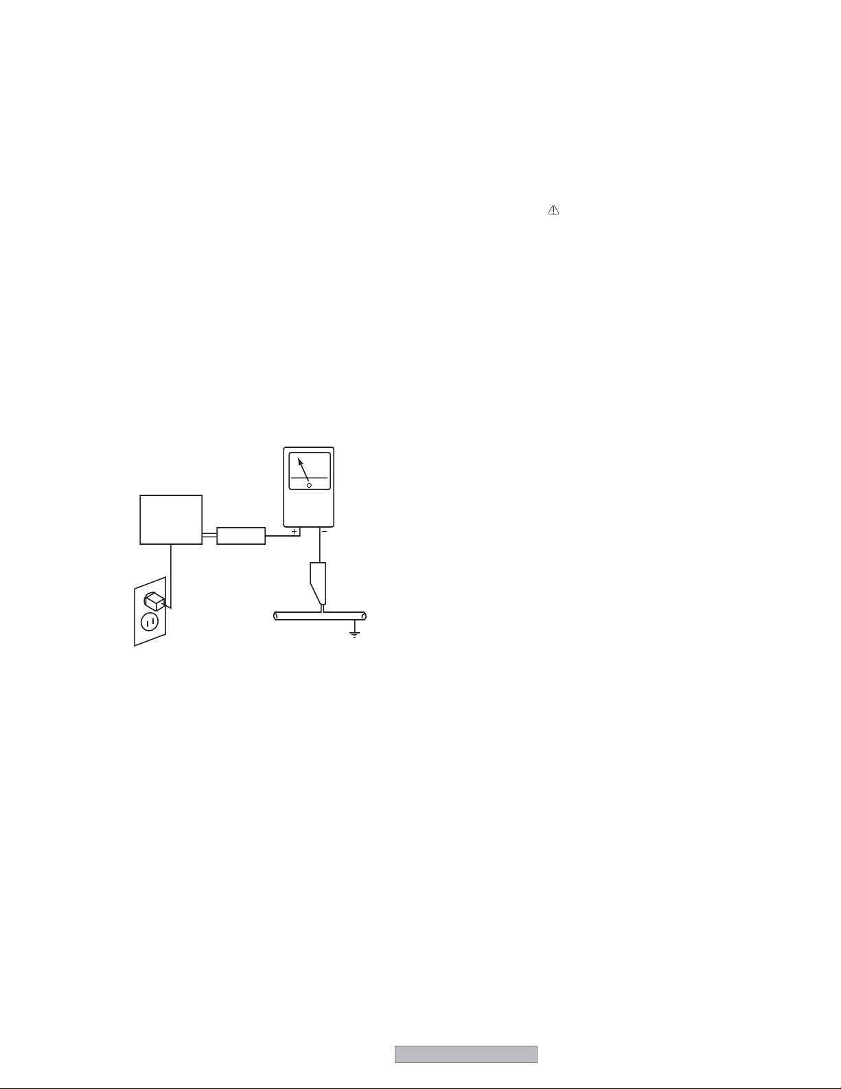
Leakage Current Hot Check
Plug the AC line cord directly into an AC power source (do not
use an isolation transformer for this check).
Turn the AC power switch on.
Using a "Leakage Current Tester", measure for current from all
exposed metal parts of the cabinet (input/output terminals,
screwheads, metal overlays, control shaft, etc.), particularly any
exposed metal part having a return path to the chassis, to a known
earth ground (water pipe, etc.). Any current measured must not
exceed 1.5mA.
PRODUCT SAFETY NOTICE
Many electrical and mechanical parts in PIONEER set have
special safety related characteristics. These are often not evident
from visual inspection nor the protection afforded by them
necessarily can be obtained by using replacement components
rated for higher voltage, wattage, etc. Replacement parts which
have these special safety characteristics are identified in this
Service Manual.
Electrical components having such features are identified by
marking with a on the schematics and on the parts list in this
Service Manual.
The use of a substitute replacement component which dose not
have the same safety characteristics as the PIONEER
recommended replacement one, shown in the parts list in this
Service Manual, may create shock, fire or other hazards.
Product Safety is continuously under review and new instructions
are issued from time to time. For the latest information, always
consult the current PIONEER Service Manual. A subscription to,
or additional copies of, PIONEER Service Manual may be
obtained at a nominal charge from PIONEER.
Reading should
not be above
1.5mA
Earth
ground
Device
under
test
Also test with
plug reversed
(Using AC adapter
plug as required)
Leakage
current
tester
Test all
exposed metal
surfaces
AC Leakage Test
ANY MEASUREMENTS NOT WITHIN THE LIMITS
OUTLINED ABOVE ARE INDICATIVE OF A POTENTIAL
SHOCK HAZARD AND MUST BE CORRECTED BEFORE
RETURNING THE SET TO THE CUSTOMER.
PD-5065
3
SAFETY SERVICE
7 Safety cautions
The matters to be observed without fail are explained below. These matters are indispensable for the preventi on of an
accident during the maintenance servicing, the [security of products] after the completi on of servicing work, and the
[prevention of the repeated occurrence of similar fault.]
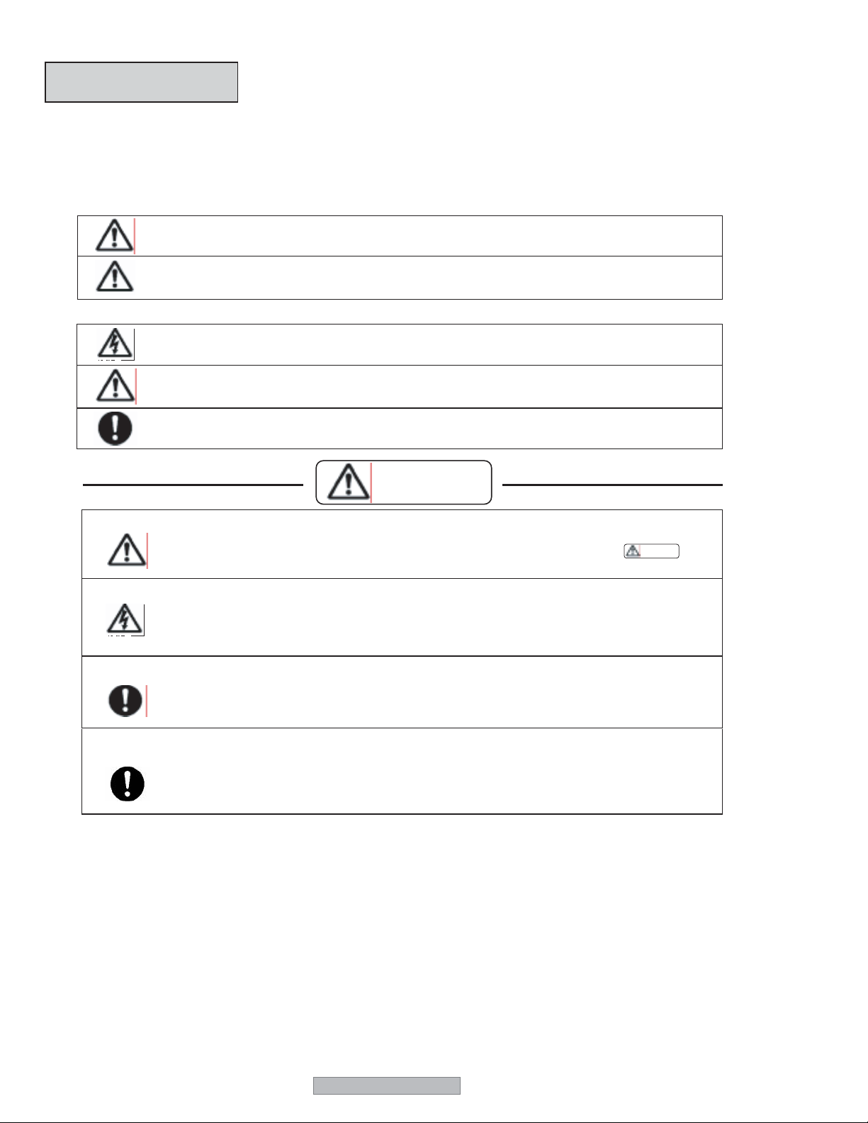
(1) The degree of danger and material damage, caused as a result of wrong use by disregarding the contents of the display”
is distinguished and explained in the table below.
WARNING
CAUTION
(2) Kinds of the matters to be observed are classified and explained in the icons shown below.
This icon indicates a dangerous place where an electric shock is anticipated.
This icon indicates the contents of “caution” that must be borne in mind, without fail.
If this display is disregarded and equipment is handled wrongly, this can be a cause of physical injury and
a fire, thus leading a person to death or serious injury.
If this display is disregarded and equipment is handled wrongly, this may lead to personal injury or
material damage.
This icon indicates the contents of “caution” that must be practiced, without fail.
WARNING
• Observe the caution matter, without fail.
• In the place where a particular caution is needed during maintenance servicing, such a caution note is displayed with a label or a
stamp that is given to the cabinet, chassis, PWB, etc. These caution notes and also the caution matters of given
in the instruction manuals, etc., must be observed, without fail.
• Be careful of an electric shock or a burn.
• The PDP module involves the sections where high voltage and high temperature are prevalent. When equipment is energized,
therefore, use working gloves in order to prevent an electric shock and a burn. At the time of transportation, disassembly,
reassembly, and the replacement of parts, such a servicing job must be done after pulling out all the connector cables that have
been connected with external equipment.
• Modification of equipment is absolutely prohibited. Use the specified parts at all times.
• If any modification is performed, the validity of the manufacturer’s warranty is lost at that moment. The personnel who did this
modification is responsible for the physical injury or the like, if it should occur as a result of the modification. The parts used are
given the safety-based characteristics, such as non-flammability or sufficient
• Danger of explosion.
• The lithium battery will give rise to explosion if its polarity is wrongly treated.
WARNING
4
PD-5065
• Observe the caution matter, without fail
• The caution matters of given in the delivery specifications, etc., must be observed, without fail.
CAUTION
• Do not give shocks and vibration.
• The panel surface (display plane) of the PDP module is made of glass. If any shocks or vibration is applied, it may be broken and
the scattered glass chips will be a cause of injury
• Do not put anything.
• Transportation must be done by enough personnel.
• Do
not put anything on the PDP module. Otherwise, this can be a cause of injury as a result of falling down or dropping caused
by imbalance.
• The PDP module is heavy. In the case of transportation, unpacking, or packing, more than two persons should do it by supporting
the top and the bottom of the product.
7 Miscellaneous caution matters
(1) This PDP module uses highly integrated semiconductor parts. Since these parts are fragile to electrostatic
charges, earth bands should be used for handling. The product should be handled where measures have been
taken against electrostatic charges.
(2) For this product, the PDP modules and the PWBs are repaired by replacement in a unit. Therefore, the units of
the PWBs must not be repaired or disassembled. Otherwise, the validity of warranty will be lost.
(3) If this PDP module is used for the fixed character display or the like as in the case of a character display board,
a phenomenon of burning (not warranted) will occur. Burning is a phenomenon that the unevenness in the
brightness is caused in the display. In such a case, the brightness in the section where the integrated display
time is longer becomes lower than the brightness in another section where the integrated display time is shorter.
This phenomenon is in proportion to the integrated display time and the brightness. For this reason, to relieve
this difficulty during servicing, do not use any still picture, but use a display by motion pictures of a video or the
like. In addition, use “STANDARD” for the screen mode and avoid using any display by “NARROW”, or “TRUE”
etc. If it is necessary to use only a still picture for unavoidable reasons, use a burning
relief function such as “PLE LOCK”, “ORBITER”, etc.
(4) When a PDP module is operated after a long time of storage, it may encounter a difficulty like a failure in
displaying a screen or unstability according to the condition of storage. In such a case, the PDP module should
be incorporated in the product and aging treatment should be carried out for about two hours (all screen display).
(5) Sulfides will deteriorate the PDP module and this is a cause of malfunction. Therefore, it is absolutely prohibited
to put any vulcanized rubber or a material containing sulfur in the vicinity of the PDP module.
(6) When taking out a PDP module from the maintenance package box, do it slowly so that the panel surface
does not get any shock or stress.
(7) If one touches the connector of the flexible cable exposed to the rear side of the PDP module, there is
danger of causing a poor contact. As such, it must be handled with utmost care. In addition, the flexible cable
is very weak in mechanical strength. Therefore, this cable must not be touched during handling.
(8) The panel surface of the PDP module is easy to be hurt and generate cracks. Therefore, it should be handled
very carefully. Never press or rub it with a hard thing. Never put it on a hard thing with the panel surface faced
downwards.
(9) When the panel surface of the PDP module is contaminated, gently wipe off the contaminant with a piece of
soft dry cloth. Liquid-state contamination can be removed by lightly pressing it, without rubbing it. If it is
difficult to remove the contamination, use a piece of cloth soaked with a neutral detergent. The cloth for
wiping off should be clean. Never use the same cloth repeatedly. If a cleansing detergent or water drops
should enter the module interior or be attached to the module surface other than the display plane at the time
of cleaning, this will give rise to the destruction of the product when the product is energized.
(10) When transporting this PDP module, use the packing materials specified in the list of parts. Once used,
such packing materials should not be used again.
(11) The PDP module is composed of a variety of parts, such as those made of materials like glass, metal,
plastics, etc. Therefore, when abandoning the PDP module, this should be done in accordance with the
relevant law of the nation or an autonomous body.
(12) This product is composed of a variety of parts, such as those made of materials like glass, metal,
plastics, etc., and those like a lithium battery , etc. Therefore, when abandoning this product, this
should be done in accordance with the relevant law of the nation or an autonomous body.
CAUTION: Risk of Explosion if Battery is replaced by an Incorrect Type. Dispose of Used Batteries
According to above the Instructions.
*1
,
*1 Only PD-5065 supports "TRUE" mode. "TRUE" mode is available, when "PICTURE SIZE" is set to off in
the "factory adjustment menu".
PD-5065
5
[Important Check Points for Good Servicing]
In this manual, procedures that must be performed during repairs are marked with the below symbol.
Please be sure to confirm and follow these procedures.
1. Product safety
Please conform to product regulations (such as safety and radiation regulations), and maintain a safe servicing environment by
following the safety instructions described in this manual.
1 Use specified parts for repair.
Use genuine parts. Be sure to use important parts for safety.
2 Do not perform modifications without proper instructions.
Please follow the specified safety methods when modification(addition/change of parts) is required due to interferences such as
radio/TV interference and foreign noise.
3 Make sure the soldering of repaired locations is properly performed.
When you solder while repairing, please be sure that there are no cold solder and other debris.
Soldering should be finished with the proper quantity.
4 Make sure the screws are tightly fastened.
Please be sure that all screws are fastened, and that there are no loose screws.
5 Make sure each connectors are correctly inserted.
Please be sure that all connectors are inserted, and that there are no imperfect insertion.
6 Make sure the wiring cables are set to their original state.
Please replace the wiring and cables to the original state after repairs.
In addition, be sure that there are no pinched wires, etc.
7 Make sure screws and soldering scraps do not remain inside the product.
Please check that neither solder debris nor screws remain inside the product.
8 There should be no semi-broken wires, scratches, melting, etc. on the coating of the power cord.
Damaged power cords may lead to fire accidents, so please be sure that there are no damages.
If you find a damaged power cord, please exchange it with a suitable one.
9 There should be no spark traces or similar marks on the power plug.
When spark traces or similar marks are found on the power supply plug, please check the connection and advise on secure
connections and suitable usage. Please exchange the power cord if necessary.
0 Safe environment should be secured during servicing.
When you perform repairs, please pay attention to static electricity, furniture, household articles, etc. in order to prevent injuries.
Please pay attention to your surroundings and repair safely.
2. Adjustments
To keep the original performance of the products, optimum adjustments and confirmation of characteristics within specification.
Adjustments should be performed in accordance with the procedures/instructions described in this manual.
3. Lubricants, Glues, and Replacement parts
Use grease and adhesives that are equal to the specified substance.
Make sure the proper amount is applied.
4. Cleaning
For parts that require cleaning, such as optical pickups, tape deck heads, lenses and mirrors used in projection monitors, proper
cleaning should be performed to restore their performances.
5. Shipping mode and Shipping screws
To protect products from damages or failures during transit, the shipping mode should be set or the shipping screws should be
installed before shipment. Please be sure to follow this method especially if it is specified in this manual.
6
PD-5065

CONTENTS
SAFETY INFORMATION......................................................................................................................................2
1. SPECIFICATIONS.............................................................................................................................................8
1.1 SPECIFICATIONS .....................................................................................................................................8
1.2 FRONT PANEL .......................................................................................................................................14
2. DIAGNOSIS ....................................................................................................................................................17
2.1 TROBLESHOOTING.................................................................................................................................17
2.2 DIAGNOSIS..............................................................................................................................................18
3. ADJUSTMENT ................................................................................................................................................33
3.1 ADJUSTING CONDITIONS......................................................................................................................33
3.2 ADJUSTING ITEMS .................................................................................................................................33
4. EXPLODED VIEWS AND PARTS LIST...........................................................................................................63
4.1 PACKING..................................................................................................................................................63
4.2 DISASSEMBLY.........................................................................................................................................69
4.3 PARTS LIST............................................................................................................................................110
5. BLOCK DIAGRAM AND SCHEMATIC DIAGRAM ........................................................................................112
5.1 CONECTION DIAGRAM ........................................................................................................................112
5.1.1 OVERALL CONNECTION DIAGRAM ..............................................................................................112
5.1.2 CONNECTOR PIN EXPLANATION..................................................................................................114
5.2 BLOCK DIAGRAM..................................................................................................................................119
5.2.1 OVERALL BLOCK DIAGRAM ..........................................................................................................119
5.2.2 CPU BLOCK.....................................................................................................................................120
6. PCB DIAGAM ................................................................................................................................................122
6.1 MAIN PWB..............................................................................................................................................122
6.2 232C, CLT and LED PWB.......................................................................................................................124
6.3 SENB, SENC, SEND and AUDIO PWB..................................................................................................125
PD-5065
7
1. SPECIFICATIONS
1.1 SPECIFICATIONS
• PD-5065 Specifications
Screen Size 43.5"(H) x 24.5"(V) inches
Aspect Ratio 16 : 9
Resolution 1365(H) x 768(V) pixels
Pixel Pitch 0.032"(H) x 0.032"(V) inches
Color Processing 4,096 steps, 68.7 billion colors
Signals
Synchronization Range Horizontal : 15.5 to 110 kHz
Input Signals RGB, NTSC (3.58/4.43), PAL (B,G,M,N),
Input Terminals
RGB
RGB 1 (Analog) mini D-sub 15-pin 1
RGB 2 (Analog) BNC (R, G, B, H/CS, V) 1*
MONLINK (Digital) HDMI
Video
INPUT 1 BNC 1
INPUT 2 RCA-pin 1
INPUT 3 S-Video: DIN 4-pin 1
DVD/HD/DTV
COMP 1 RCA-pin (Y, PB[CB], PR[CR]) 1*
COMP 2 BNC (Y, PB[CB], PR[CR]) 1*
MONLINK HDMI
Audio Stereo RCA 3 (Selectable)
External Control D-sub 9-pin 1 (RS-232C)
Sound output 9W+9W at 6 ohm
Power Supply AC100-240V 50/60Hz
Current Rating 7.6A (maximum)
Power Consumption 435W (typical), 1.5W (stand-by)
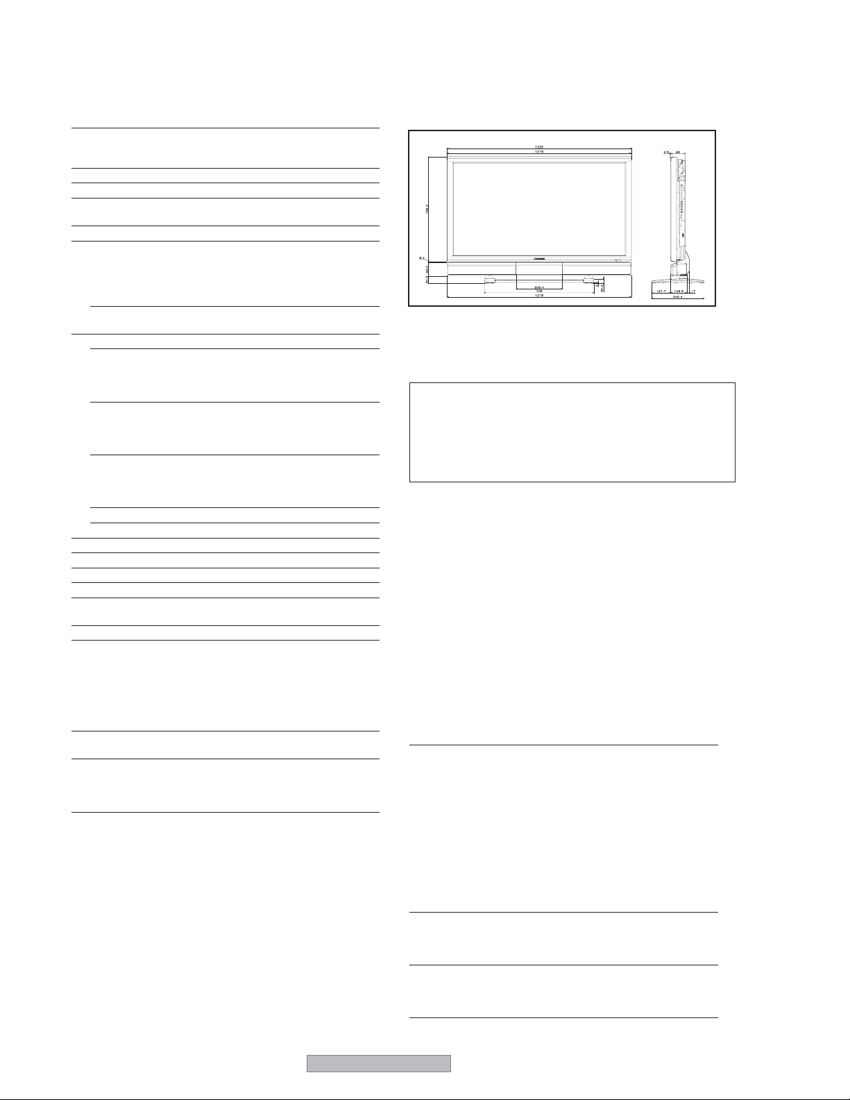
Dimensions 48.1 (W) x 35 (H) x 13.8 (D) inches
Weight 127 lbs / 57.6 kg(Net), 148 lbs / 67.4 kg(Gross)
Environmental Considerations
Operating Temperature 0°C to 40°C / 32°F to 104°F
Humidity 20 to 80% (no condensation)
Altitude 0 to 9180 feet / 0 to 2800 m
Storage Temperature -10°C to 50°C / 14°F to 122°F
Humidity 10 to 90% (no condensation)
Altitude 0 to 9840 feet / 0 to 3000 m
Front Panel User Controls
Remote Control Functions Power on/off, Input source select, Menu/
OSM Functions PICTURE(PICTURE MEMORY/CONTRAST/
1106(H) x 622(V) mm
diagonal 50"
0.81(H) x 0.81(V) mm
(automatic : step scan)
Vertical : 50.0 to 120 Hz
(automatic : step scan)
1
PAL60, SECAM, HD*
1222 (W) x 889 (H) x 350(D) mm
Input Source Select
Volume up/down/OSM Control
Exit,Volume up/down, Adjust (UP,
DOWN,LEFT, RIGHT), Zoom up/down,
Picture control buttons
BRIGHTNESS/SHARPNESS/COLOR/TINT/NR/
COLOR TEMP./WHITE BALANCE/GAMMA/
LOW TONE/SET UP LEVEL/COLOR ADJUST/
FILMMODE/PICTURE MODE), AUDIO (BASS/
TREBLE/BALANCE/AUDIO INPUT1/AUDIO
INPUT2/AUDIO INPUT3/MONITORLINK),
IMAGE ADJUST (ASPECT MODE/V-POSITION/
H-POSITION/V-HEIGHT/H-WIDTH/AUTO
PICTURE/FINE PICTURE/PICTURE ADJ.),
SETUP (LANGUAGE*/BNC INPUT/HD
SELECT/RGB SELECT/HDMI SET UP/COLOR
SYSTEM/BACK GROUND/GRAY LEVEL/S1/
S2/DISPLAY MENU/MENU ADJUST/ALL
RESET), FUNCTION (POWER MGT./INPUT
SKIP/LONG LIFE [PEAK BRIGHT / ORBITER /
INVERSE WHITE / SOFT FOCUS / ORBITER
MENU / MENU CONTRAST]), SIGNAL INFO.
, DVD*1 , DTV*
1
1
2
1
2
'
*
Bezel color is black.
The features and specifications may be subject to change
without notice.
*1HD/DVD/DTV input signals supported on this system
480P (60 Hz) 480I (60 Hz) 525P (60 Hz)
525I (60 Hz) 576P (50 Hz) 576I (50 Hz)
625P (50 Hz) 625I (50 Hz) 720P (60 Hz)
1035I (60 Hz) 1080I (50 Hz) 1080I (60 Hz)
2
The 5-BNC connectors are used as RGB/PC2 and COMP2 input.
*
Select one of them under “BNC INPUT”.
Other Features Motion compensated 3D Scan Converter (NTSC,
Accessories Remote control with two AAA batteries, Power
Regulations UL Approved (UL 60065 and CAN/CSA-C22.2
*English, German, French, Italian, Spanish, Swedish, Chinese, Russian
PAL, 480I, 576I, 525I, 625I, 1035I, 1080I), 2-3
pull down Converter (NTSC, 480I, 525I, 1035I,
1080I (60Hz)), 2-2 pull down Converter (PAL,
576I, 625I, NTSC, 480I, 525I), Digital Zoom
Function (100-900% Selectable), Self Diagnosis,
Image Burn reduction tools (PEAK BRIGHT,
INVERSE WHITE, ORBITER), Color
Temperature select (high/medium/mid low/low,
user has 4 memories), Auto Picture, Input Skip,
Color Adjust, Low Tone (3 mode), Gamma
Correction (4 mode), Plug and play (DDC1,
DDC2b, RGB3: DDC2b only),
cord, Owner’s Guide, Safety metal fittings, Ferrite
cores, Cable clamps, Registration Card, BNCRCA Adapters
No. 60065-03
Meets ICES–003 Class B requirements
Meets FCC Class B requirements
8
PD-5065
• PD-4265 Specifications
Screen Size 36.1"(H) x 20.4"(V) inches
918(H) x 518(V) mm
diagonal 42"
Aspect Ratio 16 : 9
Resolution 1024(H) x 768(V) pixels
Pixel Pitch 0.036"(H) x 0.027"(V) inches
0.897(H) x 0.675(V) mm
Color Processing 4,096 steps, 68.7 billion colors
Signals
Synchronization Range Horizontal : 15.5 to 110 kHz
(automatic : step scan)
Vertical : 50.0 to 120.0 Hz
(automatic : step scan)
Input Signals RGB, NTSC (3.58/4.43), PAL (B,G,M,N),
PAL60, SECAM, HD
1
*
, DVD*1 , DTV*
1
Input Terminals
RGB
RGB 1 (Analog)mini D-sub 15-pin 1
RGB 2 (Analog)BNC (R, G, B, H/CS, V) 1
2
*
MONLINK (Digital)HDMI
Video
INPUT1 BNC 1
INPUT 2 RCA-pin 1
INPUT 3 S-Video: DIN 4-pin 1
DVD/HD/DTV
COMP 1 RCA-pin (Y, PB[CB], PR[CR]) 1
COMP 2 BNC (Y, PB[CB], PR[CR]) 1*
1
*
1,
2
*
MONLINK HDMI
Audio Stereo RCA 3(Selectable)
External Control D-sub 9-pin 1(RS-232C)
Sound output 8W+8W at 6 ohm
Power Supply AC100-240V 50/60Hz
Current Rating 5.2A (maximum)
Power Consumption 305W (typical), 1.5W(stand-by)
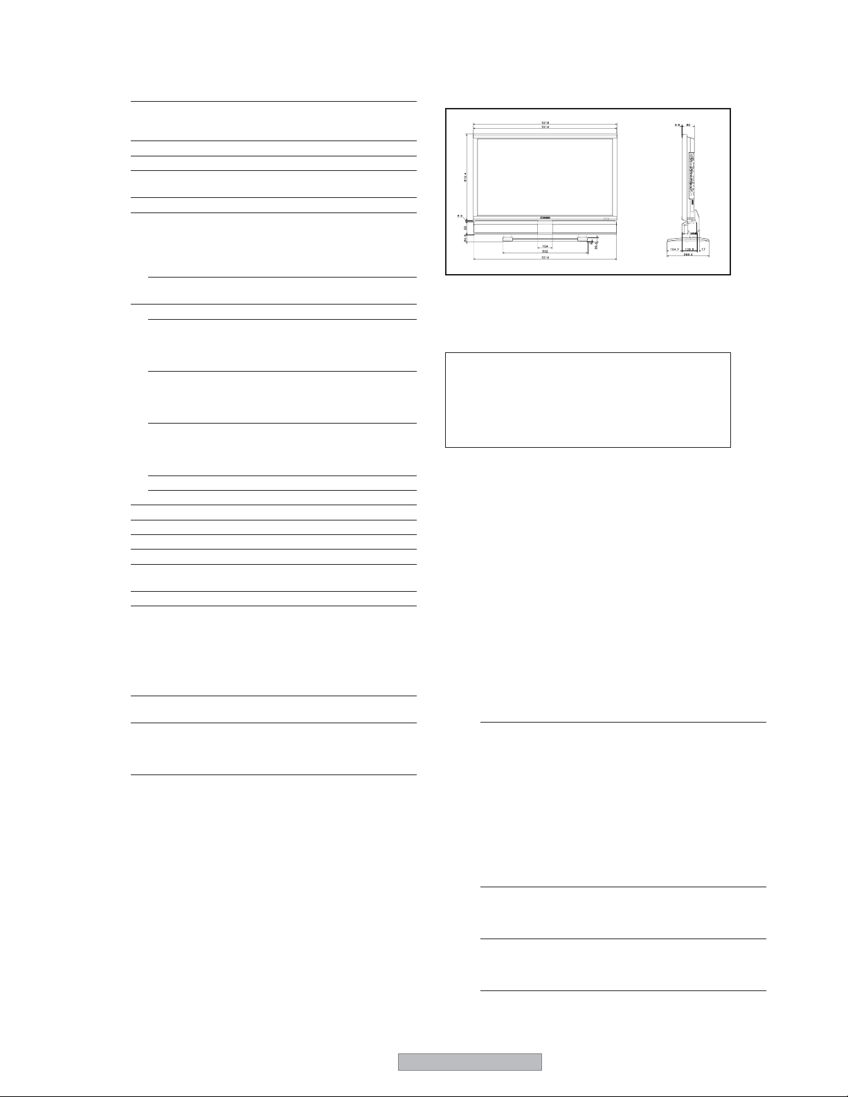
Dimensions 40 (W) x 30 (H) x 11.8 (D) inches
1018 (W) x 763 (H) x 300(D) mm
Weight 95 lbs / 43 kg(Net), 113 lbs / 51.0 kg(Gross)
Environmental Considerations
OperatingTemperature 0°C to 40°C / 32°F to 104°F
Humidity 20 to 80% (no condensation)
Altitude 0 to 9180 feet / 0 to 2800m
StorageTemperature -10°C to 50°C / 14°F to 122°F
Humidity
10 to 90% (no condensation)
Altitude 0 to 9840 feet / 0 to 3000 m
Front Panel User Controls Input source select,
Volume up/down, OSM Control
RemoteControl Functions
Power on/off, Input source select, Menu/
Exit,Volume up/down, Adjust (UP,
DOWN,LEFT, RIGHT), Zoom up/down,
Picture control buttons
OSM Functions PICTURE(PICTURE MEMORY/CONTRAST/
BRIGHTNESS/SHARPNESS/COLOR/TINT/
NR/COLOR TEMP./WHITE BALANCE/
GAMMA/LOW TONE/SET UP LEVEL/
COLORADJUST/FILM MODE/PICTURE
MODE), AUDIO (BASS/TREBLE/BALANCE/
AUDIO INPUT1/AUDIO INPUT2/AUDIO
INPUT3/MONITORLINK), IMAGE ADJUST
(ASPECT MODE/V-POSITION/H-POSITION/
V-HEIGHT/H-WIDTH/AUTO PICTURE/FINE
PICTURE/PICTURE ADJ.),
SETUP (LANGUAGE*/BNC INPUT/HD
SELECT/RGB SELECT/HDMI SET UP/
COLOR SYSTEM/BACK GROUND/GRAY
LEVEL/S1/S2/DISPLAY MENU/MENU
ADJUST/ALL RESET), FUNCTION (POWER
MGT./INPUT SKIP/LONG LIFE [PEAK
BRIGHT/ ORBITER / INVERSE WHITE /
SOFT FOCUS / ORBITER MENU/MENU
CONTRAST]), SIGNAL INFO.
Bezel color is black.
Thefeatures and specifications may be subject to change without
notice.
*1HD/DVD/DTV input signals supported on this system
480P (60 Hz) 480I (60 Hz) 525P (60 Hz)
525I (60 Hz) 576P (50 Hz) 576I (50 Hz)
625P (50 Hz) 625I (50 Hz) 720P (60 Hz)
1035I (60 Hz) 1080I (50 Hz) 1080I (60 Hz)
2
The 5-BNC connectors are used as RGB/PC2 and COMP2 input.
*
Select one of them under “BNC INPUT”
Other Features Motion compensated 3D Scan Converter (NTSC,
PAL, 480I, 576I, 525I, 625I, 1035I, 1080I), 2-3
pull down Converter (NTSC, 480I, 525I, 1035I,
1080I (60Hz)), 2-2 pull down Converter (PAL,
576I, 625I, NTSC, 480I, 525I), Digital Zoom
Function (100-900% Selectable), Self Diagnosis,
Image Burn reduction tools (PEAK BRIGHT,
INVERSE WHITE, ORBITER), Color
Temperature select (high/middle/middle low/low,
user has 4 memories), Auto Picture, Input Skip,
Color Adjust, Low Tone (3 mode), Gamma
Correction (4 mode), Plug and play (DDC1,
DDC2b, RGB3: DDC2b only)
Accessories Remote control with two AAA batteries, Power
cord, Owner’s Guide, Safety metal fittings, Ferrite
cores, Cable clamps, Registration Card, BNCRCA Adapters
Regulations UL Approved (UL60065,and CAN/CSA– C22.2)
No.60065-03
Meets ICES-003 Class B requirements
Meets FCC Class B requirements
*English, German, French, Italian, Spanish, Swedish, Chinese, Russian
PD-5065
9
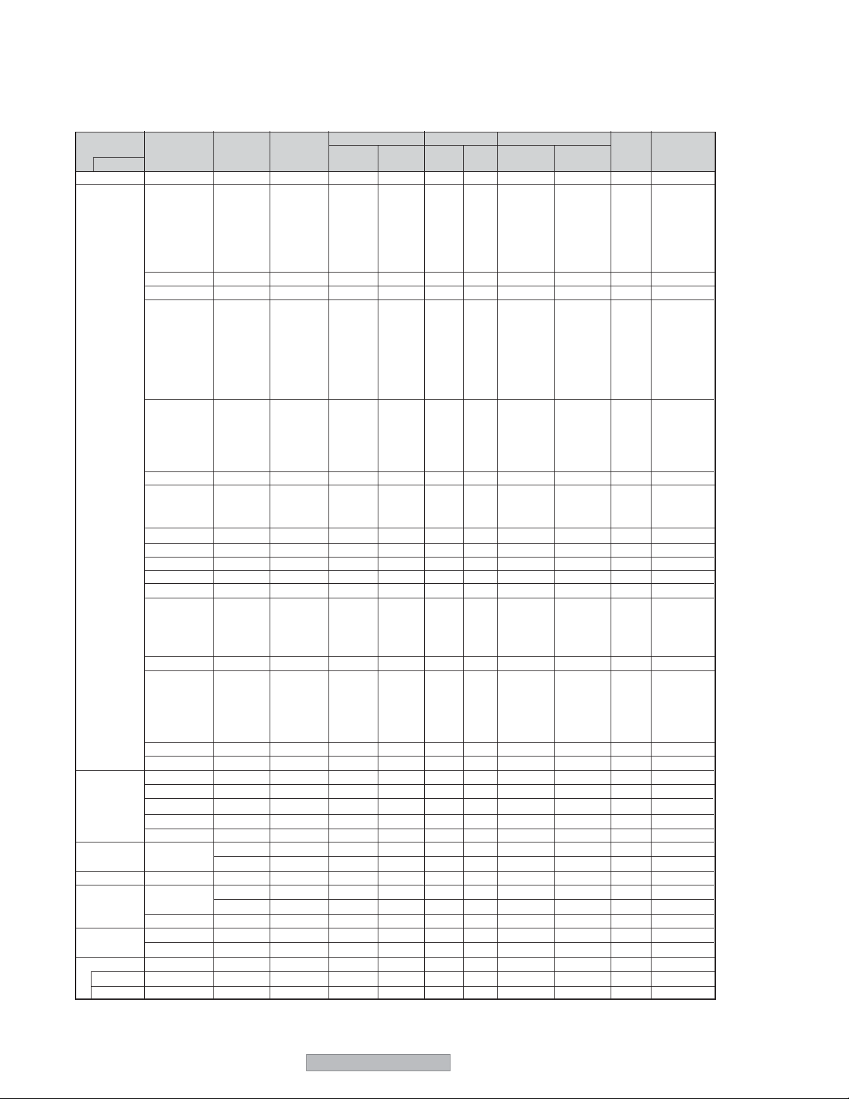
TABLE OF SIGNAL SUPPORTED
Supported resolution (PD-5065)
• When the screen mode is NARROW, each signal is converted to a 1024 dots 768 lines signal. (Except for *
• When the screen mode is STANDARD, each signal is converted to a 1365 dots 768 lines signal. (Except for *
Computer input signals supported by this system
Model
Signal Type
IBM PC/AT*
7
compatible
computers
Apple
Macintosh*
Work Station
(EWS4800)
Work Station(HP)
Work Station
(SUN)
5*7
7
*
7
*
7
*
Work Station
(SGI)
IDC-3000G
PAL625P
NTSC525P
Dots x lines
640 x 400
640 x 480
848 x 480
852 x 480*
800 x 600
1024 x 768
1152 x 864
1280 x 768
1280 x 768*
1280 x 800*
1280 x 854*
1360 x 765
1360 x 768
1376 x 768
1280 x 1024
1680 x 1050*
1600 x 1200
1920 x 1200*
1920 x 1200RB
640 x 480
832 x 624
1024 x 768
1152 x 870
1440 x 900*
1280 x 1024
1280 x 1024
1152 x 900
1280 x 1024
1024 x 768
1280 x 1024
768 x 576
640 x 480
Vertical
frequency
(Hz)
1
8
8
8
8
8
8
*
8
70.1
59.9
72.8
75.0
85.0
100.4
120.4
60.0
60.0
56.3
60.3
72.2
75.0
85.1
99.8
120.0
60.0
70.1
75.0
85.0
100.6
75.0
56.2
59.8
69.8
60.0
60.0
60.0
60.0
59.9
60.0
75.0
85.0
100.1
60.0
60.0
65.0
70.0
75.0
85.0
60.0
60.0
66.7
74.6
74.9
75.1
60.0
60.0
71.2
72.0
66.0
76.0
76.1
60.0
60.0
50.0
59.9
Horizontal
frequency
(kHz)
31.5
31.5
37.9
37.5
43.3
51.1
61.3
31.0
31.7
35.2
37.9
48.1
46.9
53.7
63.0
75.7
48.4
56.5
60.0
68.7
80.5
67.5
45.1
48.0
56.0
49.7
53.1
47.7
47.7
48.3
64.0
80.0
91.1
108.5
65.3
75.0
81.3
87.5
93.8
106.3
74.6
74.0
35.0
49.7
60.2
68.7
56.0
64.6
75.1
78.1
61.8
71.7
81.1
49.7
63.9
31.4
31.5
Sync Polarity Presence
Horizontal
Sync on G
Sync on G
Sync on G
Sync on G
C Sync
C Sync
C Sync
NEG
NEG
NEG
NEG
NEG
NEG
NEG
POS
NEG
POS
POS
POS
POS
POS
POS
POS
NEG
NEG
POS
POS
NEG
POS
POS
POS
NEG
NEG
NEG
POS
POS
NEG
POS
POS
POS
POS
NEG
POS
POS
POS
POS
POS
NEG
NEG
NEG
NEG
NEG
– –
– –
– –
NEG
NEG
Vertical
NEG
NEG
NEG
NEG
NEG
NEG
NEG
POS
NEG
POS
POS
POS
POS
POS
POS
POS
NEG
NEG
POS
POS
NEG
POS
POS
NEG
POS
NEG
NEG
POS
POS
POS
POS
POS
POS
POS
NEG
POS
POS
POS
POS
POS
NEG
NEG
Sync on G
Sync on G
Sync on G
Sync on G
NEG
NEG
NEG
– –
C Sync
C Sync
C Sync
– –
– –
NEG
NEG
Horizontal
YES
YES
YES
YES
YES
YES
YES
YES
YES
YES
YES
YES
YES
YES
YES
YES
YES
YES
YES
YES
YES
YES
YES
YES
YES
YES
YES
YES
YES
YES
YES
YES
YES
YES
YES
YES
YES
YES
YES
YES
YES
YES
– –
– –
– –
– –
YES
YES
YES
– –
– –
– –
– –
– –
– –
YES
YES
Vertical
YES
YES
YES
YES
YES
YES
YES
YES
YES
YES
YES
YES
YES
YES
YES
YES
YES
YES
YES
YES
YES
YES
YES
YES
YES
YES
YES
YES
YES
YES
YES
YES
YES
YES
YES
YES
YES
YES
YES
YES
YES
YES
– –
– –
– –
– –
YES
YES
YES
– –
– –
– –
– –
– –
– –
YES
YES
2, *3
)
2
)
Screen mode
NARROW
(4:3)
– –
YES
YES
YES
YES
YES
YES
– –
– –
YES
YES
YES
YES
YES
YES
YES
2
YES*
2
YES*
2
YES*
2
YES*
2
YES*
YES
– –
– –
– –
– –
– –
– –
– –
– –
3
YES*
3
YES*
3
YES*
3
YES*
– –
YES
YES
YES
YES
YES
– –
– –
YES
YES
2
YES*
YES
– –
3
YES*
3
YES*
3
YES*
YES
YES
3
YES*
2
YES*
3
YES*
6
YES*
6
YES*
STANDARD
(16:9)
YES
YES
YES
YES
YES
YES
YES
YES
YES
YES
YES
YES
YES
YES
YES
YES
YES
YES
YES
YES
YES
YES
YES
YES
YES
YES
YES
2
YES*
2
YES*
YES
YES
YES
YES
YES
YES
YES
YES
YES
YES
YES
YES
YES
YES
YES
YES
YES
YES
YES
YES
YES
YES
YES
YES
YES
YES
6
YES*
RGB
select*
YES
STILL
– –
STILL
– –
– –
– –
WIDE2
WIDE1
STILL
STILL
– –
– –
– –
– –
NO
STILL
– –
STILL
– –
– –
STILL
WIDE1
WIDE3
WIDE1
WIDE1
WIDE2
WIDE1
WIDE1
WIDE2
STILL
– –
– –
– –
WIDE4
– –
– –
– –
– –
– –
WIDE2
WIDE3
– –
– –
WIDE1
WIDE1
– –
– –
– –
– –
– –
– –
– –
– –
– –
– –
MOTION
4
Memory
4
5
7
8
9
41
42
19
17
11
12
13
14
15
43
44
24
25
26
27
45
51
52
80
66
21
37
22
22
53
29
30
40
47
38
54
55
56
57
58
81
88
6
16
28
39
89
29
48
59
60
61
30
62
29
31
32
10
PD-5065

*1 Only when using a graphic accelerator board that is capable of displaying 852 x 480.
*2 The picture is displayed in the original resolution.
*3 The aspect ratio is 5:4. This signal is converted to a 960 dots x 768 lines signal.
*4 Normally the RGB select mode suite for the input signals is set automatically. If the picture is not displayed
properly, set the RGB mode prepared for the input signals listed in the table above.
*5 To connect the display to Macintosh computer, use a monitor adapter (NOT INCLUDED).
*6 Other screen modes (EXPAND and STRETCH) are available as well.
*7 When viewing a moving picture at a vertical frequency greater than 65Hz, the picture may sometimes be unstable
y). If this occurs, please set the refresh rate of the external equipment to 60Hz.
(jump
To view 480I@60Hz (480 interlaced lines, 60Hz refresh rate) or 576I@50Hz (567 interlaced lines, 50Hz
refresh rate) when sync polarity is “Sync on Green”, set “RGB SELECT” to “MOTION”.
*8 CVT standard compliant.
NOTE:
•
While the input signals comply with the resolution listed in the table above, you may have to adjust the position and
size of the picture or the fine picture because of errors in synchronization of your computer.
•
When a 1280 dots x 1024 lines signal or 1600 dots x 1200 lines signal is input to the monitor, the picture will be
compressed.
•
This display has a resolution of 1365 dots x 768 lines. It is recommended that the input signal should be XGA, wide
XGA, or equivalent.
•
With digital input some signals are not accepted.
•
The sync may be disturbed when a nonstandard signal other than the aforementioned is input.
•
If you are connecting a composite sync signal, use the HD terminal.
• “IBM PC/AT” and “XGA” are registered trademarks of International Business Machines, Inc. of the United
States.
• “Apple Macintosh” is a registered trademark of Apple Computer, Inc. of the United States.
PD-5065
11
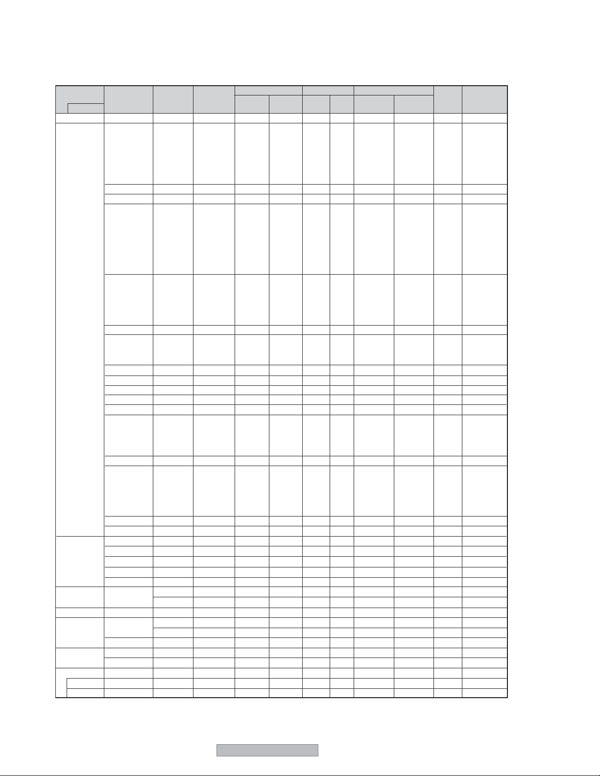
Supported resolution (PD-4265)
• When the screen mode is NARROW, each signal is converted to a 768 dots 768 lines signal. (Except for *3)
• When the screen mode is STANDARD, each signal is converted to a 1024 dots 768 lines signal.
Computer input signals supported by this system
Model
Signal Type
IBM PC/AT*
7
compatible
computers
Apple
Macintosh*
Work Station
(EWS4800)
Work Station(HP)
Work Station
(SUN)
5 *7
7
*
*
7
*
Work Station
(SGI)
IDC-3000G
PAL625P
NTSC525P
Dots x lines
640 x 400
640 x 480
848 x 480
852 x 480*
800 x 600
1024 x 768
1152 x 864
1280 x 768
1280 x 768*
1280 x 800*
1280 x 854*
1360 x 765
1360 x 768
1376 x 768
1280 x 1024
1680 x 1050*
1600 x 1200
1920 x 1200*
1920 x 1200RB
640 x 480
832 x 624
1024 x 768
1152 x 870
1440 x 900*
1280 x 1024
7
1280 x 1024
1152 x 900
1280 x 1024
1024 x 768
1280 x 1024
768 x 576
640 x 480
Vertical
frequency
(Hz)
1
8
8
8
8
8
8
*
8
70.1
59.9
72.8
75.0
85.0
100.4
120.4
60.0
60.0
56.3
60.3
72.2
75.0
85.1
99.8
120.0
60.0
70.1
75.0
85.0
100.6
75.0
56.2
59.8
69.8
60.0
60.0
60.0
60.0
59.9
60.0
75.0
85.0
100.1
60.0
60.0
65.0
70.0
75.0
85.0
60.0
60.0
66.7
74.6
74.9
75.1
60.0
60.0
71.2
72.0
66.0
76.0
76.1
60.0
60.0
50.0
59.9
Horizontal
frequency
(kHz)
31.5
31.5
37.9
37.5
43.3
51.1
61.3
31.0
31.7
35.2
37.9
48.1
46.9
53.7
63.0
75.7
48.4
56.5
60.0
68.7
80.5
67.5
45.1
48.0
56.0
49.7
53.1
47.7
47.7
48.3
64.0
80.0
91.1
108.5
65.3
75.0
81.3
87.5
93.8
106.3
74.6
74.0
35.0
49.7
60.2
68.7
56.0
64.6
75.1
78.1
61.8
71.7
81.1
49.7
63.9
31.4
31.5
Sync Polarity Presence
Horizontal
NEG
NEG
NEG
NEG
NEG
NEG
NEG
POS
NEG
POS
POS
POS
POS
POS
POS
POS
NEG
NEG
POS
POS
NEG
POS
POS
POS
NEG
NEG
NEG
POS
POS
NEG
POS
POS
POS
POS
NEG
POS
POS
POS
POS
POS
NEG
NEG
Sync on G
Sync on G
Sync on G
Sync on G
NEG
NEG
NEG
C Sync
C Sync
C Sync
NEG
NEG
– –
– –
– –
Vertical
NEG
NEG
NEG
NEG
NEG
NEG
NEG
POS
NEG
POS
POS
POS
POS
POS
POS
POS
NEG
NEG
POS
POS
NEG
POS
POS
NEG
POS
NEG
NEG
POS
POS
POS
POS
POS
POS
POS
NEG
POS
POS
POS
POS
POS
NEG
NEG
Sync on G
Sync on G
Sync on G
Sync on G
NEG
NEG
NEG
– –
C Sync
C Sync
C Sync
– –
– –
NEG
NEG
Horizontal
YES
YES
YES
YES
YES
YES
YES
YES
YES
YES
YES
YES
YES
YES
YES
YES
YES
YES
YES
YES
YES
YES
YES
YES
YES
YES
YES
YES
YES
YES
YES
YES
YES
YES
YES
YES
YES
YES
YES
YES
YES
YES
– –
– –
– –
– –
YES
YES
YES
– –
– –
– –
– –
– –
– –
YES
YES
Vertical
YES
YES
YES
YES
YES
YES
YES
YES
YES
YES
YES
YES
YES
YES
YES
YES
YES
YES
YES
YES
YES
YES
YES
YES
YES
YES
YES
YES
YES
YES
YES
YES
YES
YES
YES
YES
YES
YES
YES
YES
YES
YES
– –
– –
– –
– –
YES
YES
YES
– –
– –
– –
– –
– –
– –
YES
YES
NARROW
Screen mode
(4:3)
– –
YES
YES
YES
YES
YES
YES
– –
– –
YES
YES
YES
YES
YES
YES
YES
2
YES*
2
YES*
2
YES*
2
YES*
2
YES*
YES
– –
– –
– –
– –
– –
– –
– –
– –
3
YES*
3
YES*
3
YES*
3
YES*
– –
YES
YES
YES
YES
YES
– –
– –
YES
YES
2
YES*
YES
– –
3
YES*
3
YES*
3
YES*
YES
YES
3
YES*
2
YES*
3
YES*
6
YES*
6
YES*
STANDARD
(16:9)
YES
YES
YES
YES
YES
YES
YES
YES
YES
YES
YES
YES
YES
YES
YES
YES
YES
YES
YES
YES
YES
YES
YES
YES
YES
YES
YES
2
YES*
2
YES*
YES
YES
YES
YES
YES
YES
YES
YES
YES
YES
YES
YES
YES
YES
YES
YES
YES
YES
YES
YES
YES
YES
YES
YES
YES
YES
6
YES*
RGB
select*
YES
STILL
– –
STILL
– –
– –
– –
WIDE2
WIDE1
STILL
STILL
– –
– –
– –
– –
NO
STILL
– –
STILL
– –
– –
STILL
WIDE1
WIDE3
WIDE1
WIDE1
WIDE2
WIDE1
WIDE1
WIDE2
STILL
– –
– –
– –
WIDE4
– –
– –
– –
– –
– –
WIDE2
WIDE3
– –
– –
WIDE1
WIDE1
– –
– –
– –
– –
– –
– –
– –
– –
– –
– –
MOTION
4
Memory
4
5
7
8
9
41
42
19
17
11
12
13
14
15
43
44
24
25
26
27
45
51
52
80
66
21
37
22
22
53
29
30
40
47
38
54
55
56
57
58
81
88
6
16
28
39
89
29
48
59
60
61
30
62
29
31
32
12
PD-5065

*1 Only when using a graphic accelerator board that is capable of displaying 852 x 480.
*2 The picture is displayed in the original resolution. The picture will be compressed for other signals.
*3 The aspect ratio is 5:4. This signal is converted to a 720 dots x 768 lines signal.
*4 Normally the RGB select mode suite for the input signals is set automatically. If the picture is not displayed
properly, set the RGB mode prepared for the input signals listed in the table above.
*5 To connect the monitor to Macintosh computer, use the monitor adapter (D-Sub 15-pin) to your computer’s
video port.
*6 Other screen modes (EXPAND and STRETCH) are available as well.
*7 When viewing a moving picture at a vertical frequency greater than 65Hz, the picture may sometimes be
unstable (jumpy). If this occurs, please set the refresh rate of the external equipment to 60Hz.
To view 480I@60Hz (480 interlaced lines, 60Hz refresh rate) or 576I@50Hz (567 interlaced lines, 50Hz
refresh rate) when sync polarity is “Sync on Green”, set “RGB SELECT” to “MOTION”.
*8 CVT standard compliant.
NOTE:
•
While the input signals comply with the resolution listed in the table above, you may have to adjust the position and
size of the picture or the fine picture because of errors in synchronization of your computer.
•
This monitor has a resolution of 1024 dots x 768 lines. It is recommended that the input signal should be XGA, wide
XGA, or equivalent.
•
With digital input some signals are not accepted.
•
The sync may be disturbed when a nonstandard signal other than the aforementioned is input.
•
If you are connecting a composite sync signal, use the HD terminal.
•“IBM PC/AT” and “XGA” are registered trademarks of International Business Machines, Inc. of the United States.
• “Apple Macintosh” is a registered trademark of Apple Computer, Inc. of the United States.
PD-5065
13
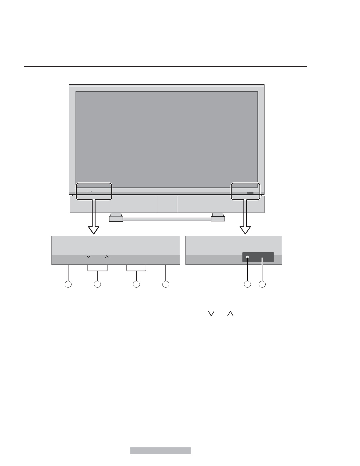
1.2 FRONT PANEL
Part Names and Function
Front View
VOLUME
MENU/ENTER LEFT/-RIGHT/+INPUT/EXIT
MENU/ENTER LEFT/
6
VOLUME
5
-
4
1 REMOTE SENSOR WINDOW
Receives the signals from the remote control.
2 POWER/STANDBY Indicator
When the power is on ............................. Lights green.
When the power is in the standby mode ... Lights red.
3 INPUT / EXIT BUTTON
Switches the input.
The available inputs depend on the setting of “BNC
INPUT”, “RGB SELECT” and “HDMI SET UP”.
Functions as the EXIT buttons in the On-Screen Menu
mode.
RIGHT/+INPUT/EXIT
3
1
2
5 VOLUME
and
Adjusts the volume. Functions as the ADJUST ( /
buttons in the On-Screen Menu mode.
6 MENU/ENTER BUTTON
Display the main menu or select a menu item. The
MENU/ENTER button can also be used to turn the
display on or off.
To turn the display on, press MENU/ENTER button.
To turn the display off, press and hold the MENU/
ENTER button for five seconds.
)
4 LEFT/– and RIGHT/+
Functions as the ADJUST (
Screen Menu mode.
14
) buttons in the On-
/
PD-5065
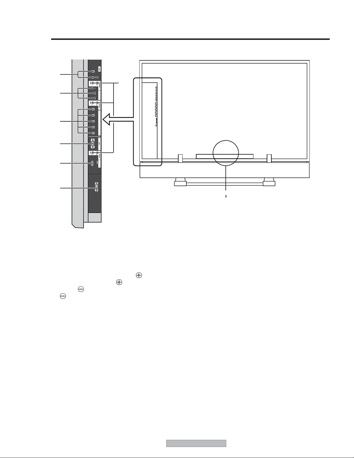
Side View Rear View
INPUT 1
INPUT 2
C
INPUT 3
D
E
COMPONENT 1
R/Cr/Pr G/Y
RGB2/COMPONENT2
B/Cb/Pb H V
F
G
H
MONITOR LINK
MONITORLINK
CONTROL
I
A AC IN
Connect the included power cord here.
B EXT SPEAKER L and R
Maintain the correct polarity. The
wire is connected to the
and the
(negative) speaker wire is connected to the
EXT SPEAKER terminal
EXT SPEAKER terminal on both LEFT and
RIGHT channels.
C INPUT1, 2, 3 (BNC, RCA, S-Video)
Connect VCR s, DVD s or Video Cameras, etc. here.
D AUDIO1, AUDIO2, AUDIO3
These are audio input terminals.
The input is selectable. Select which video input to
assign them to from the audio menu screen.
(positive) speaker
AB
F RGB2 / COMPONENT2
COMP2: You can connect DVDs, High
Definition sources, Cable Boxes, etc.
here.
This input can be set for use with an
RGB or component source.
RGB2: You can connect an analog RGB signal
and the syncronization signal.
G RGB1 (D-Sub)
Connect an analog RGB signal from a computer, etc.
here.
H MONITORLINK/HDMI
Connect a digital signal from a source with a HDMI
output.
E COMPONENT1
Connect DVD s, Cable Boxes or High Definition
sources, etc. here.
I MONITORLINK CONTROL (RS-232C)
This terminal is used when operating and controlling
the display externally (by external control).
PD-5065
15
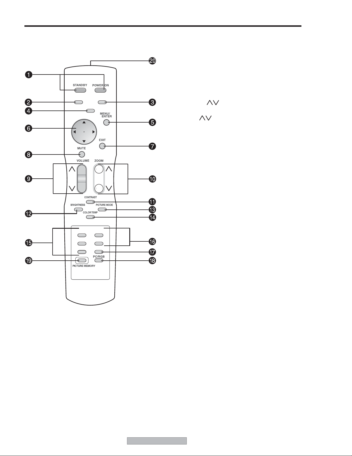
Remote Control
FORMAT
DEVICE
INFO
COMP 1
COMP 2
MONLINK
SLEEP
ADJUST
INPUT 1
INPUT 2
INPUT 3
1 POWER ON/STANDBY
Switches the power to ON or STANDBY mode.
2 SLEEP
Press this button to activate the off timer.
3 INFO
Displays the source settings on the screen.
4 FORMAT
Automatically detects the signal and sets the aspect
ratio. FORMAT button is not active for all signals.
5 MENU/ENTER
Press this button to access the Menu.
Press this button during the display of the main menu
to go to the sub menu.
6 ADJUST ( / / /
)
Use these buttons to select items or settings and to
adjust settings or switch the display patterns.
7 EXIT
Press this button to exit the MAIN MENU. Press this
button during the display of the sub menu to return to
the previous menu.
8 MUTE
Press this button to mute the audio.
9 VOLUME (
)
Press this button to adjust audio volume.
0 ZOOM (
)
Press this button to enlarge or reduce the image.
- CONTRAST
Press this button to adjust contrast directly.
= BRIGHTNESS
Press this button to adjust brightness directly.
~ PICTURE MODE
Press this button to adjust picture mode directly.
! COLOR TEMP
Press this button to adjust color tone directly.
@ INPUT1, 2, 3
Press one of these buttons to select INPUT1 or INPUT2
or INPUT3 as the source.
INPUT 1-3 can also be selected using the INPUT/EXIT
button on the front panel of the display.
# COMP1, 2
Press one of these buttons to select COMP1 or COMP2
as the source.
COMP 1-2 can also be selected using the INPUT/EXIT
button on the front panel of the display.
$ MONLINK
Press this button to select MONLINK/HDMI as the
source.
% PC/RGB
Press this button to select PC/RGB as the source. PC/
RGB can also be selected using the INPUT SELECT
button on the display.
^ PICTURE MEMORY
Switches sequentially between picture memory settings
1 to 6
& Remote control signal transmitter
Transmits the remote control signal
16
PD-5065

2. DIAGNOSIS
2.1 TROUBLESHOOTING
• Problems in the power supply, such as "Failure in Power ON" or "LED flashing or lighting (alarm display)"
→ 1. Go to Power failure (P18).
• Problems in the images, such as "No pictures available"
→ 2. Go to Image errors (P24).
• No video loop-out signal is generated.
→ The MAIN PWB is faulty.
• "Remote control not effective"
→ 3. Go to Audio errors (P31).
• "Remote control not effective"
→ 4. Go to Remote control is not effective (P32).
PD-5065
17
2.2 DIAGNOSIS
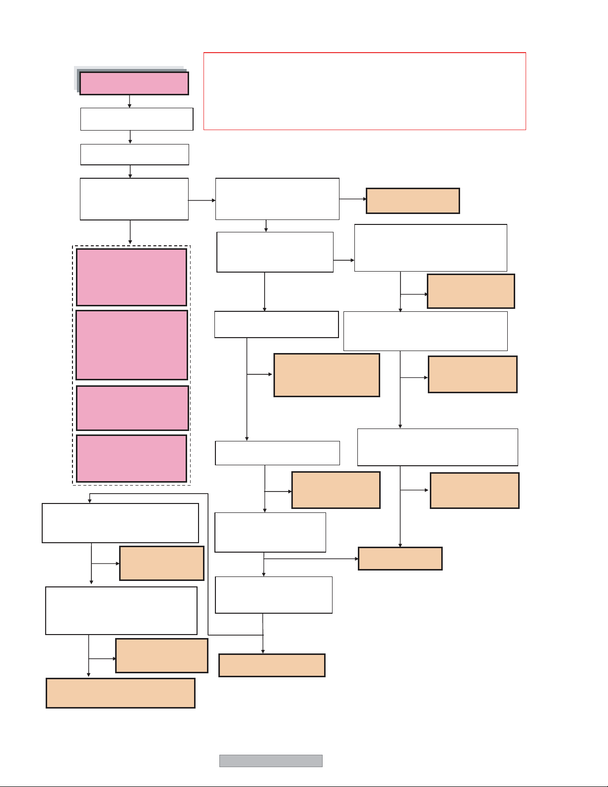
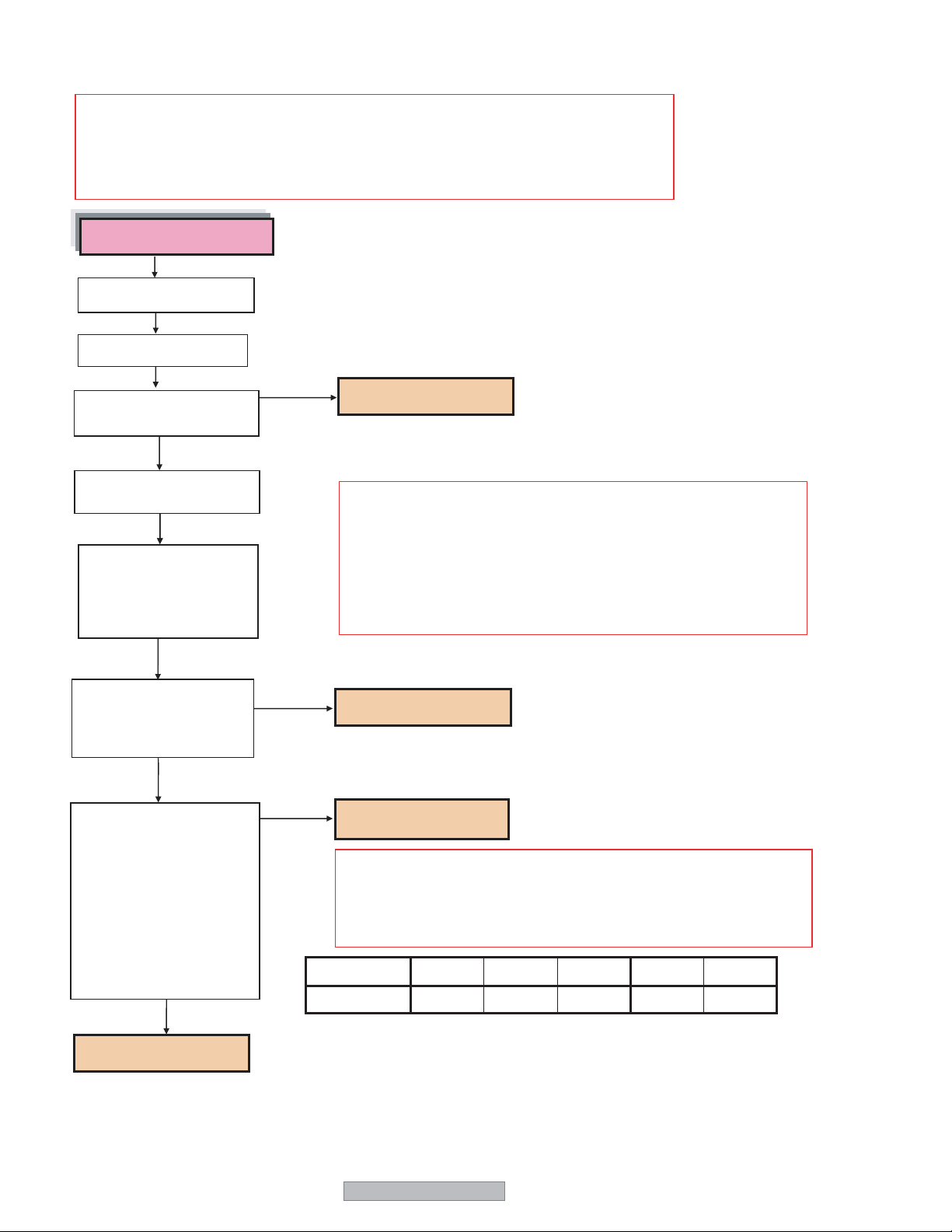
1. Power failure
(1) Power failure
(1)The power supply is
not turned on.
Disconnect the power cord.
Connect the power cord.
(Caution) If any abnormality is sensed in such a manner that the LED flashes
or lights, all the power lines other than those of 7Vdc (M+7V) and
5Vdc (M+5V) are automatically turned off in about 10 seconds.
When checking the power lines other than those of M+7V and
M+5V, a circuit tester or the like should have been connected in
advance. Is the AC power output available at the AC connector
Is the POWER/STANDBY
lamp lit?
YES
(2) Blinking in green
(Alarm of temperature
sensor error or fan
error)Go to (P19, P20 )
(3) Blinking in red after
repeating reciprocal flash
in red and green (POWER
ON OFF) 3times (Alarm of
temperature error) Go to
(P21).
(4) Alternation blinking in
red and green (Alarm of
panel error) Go to
(P22).
(5) Lighting in green, and
then in red (Alarm of
power line error) Go to
(P23).
Is a 5Vdc output available in the state
that the LD connector is disconnected
and the main power is turned ON?
The LD connector
YES
or the LED PWB is
NO
Is a 5Vdc output available in the
state thatthe RS connector is
disconnected and the main power is
turned ON?
NO
YES
fault.
The RS connector or
the 232C PWB is
fault.
Is the AC power output
NO
available at the AC connector
(power cord)?
YES
Is a 6.8Vdc output
available at Pin 1 of the
PM connector?
YES
Is a 6.8Vdc output available at
Pin 1 of the PW connector?
The PW connector is
NO
fault.
YES
Is a 6.8Vdc output available at
Pin 6 of the PM connector?
NO
YES
Is a 4.9Vdc output
available at Pin 3 of the
PM connector?
NO
Is a 5Vdc output available at
Pin 4 of the PW connector?
NO
The MAIN PWB is fault.
YES
YES
NO
The power cord is
defective.
Is a 6.8Vdc output available in the
state that the LD connector is
NO
disconnected and the main power is
turned ON?
Is a 6.8Vdc output available in the state
that the PW connector is disconnected
and the main power is turned ON?
Is a 6.8Vdc output available in the state
that the PM connector is disconnected
and the main power is turned ON?
The PM connector or
the MAIN PWB is
fault.
The power unit is
fault.
NO
NO
NO
The LD connector
YES
or the LED PWB is
fault.
The PW connector is
YES
fault.
YES
The PM connector or
the MAIN PWB is
fault.
The PW connector, or the MAIN PWB
is fault.
18
PD-5065
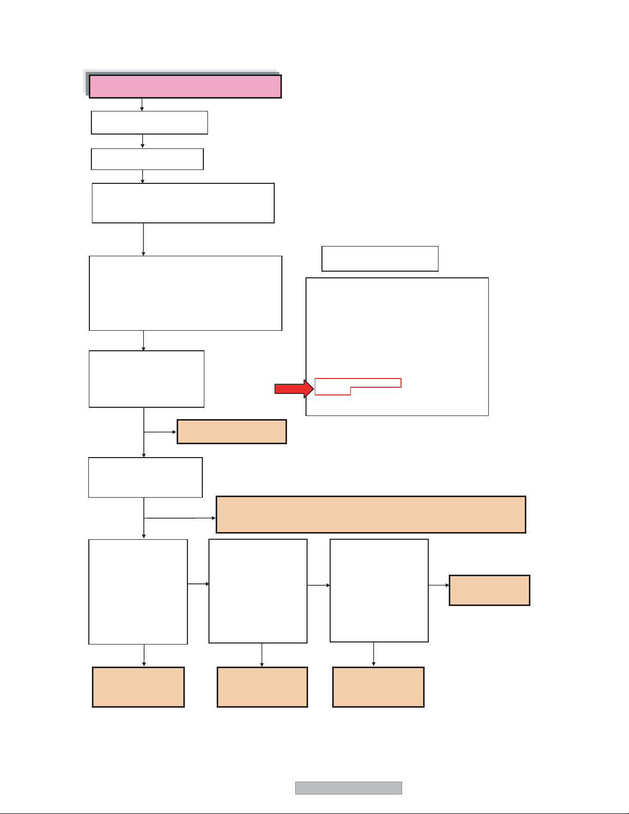
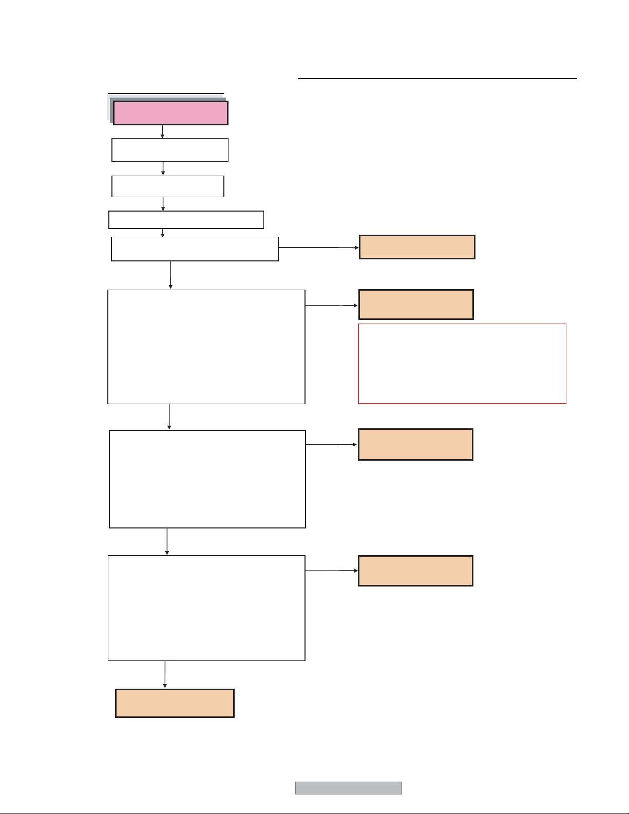
(2) Blinking in green
1 Alarm of temperature sensor error
Blinking in green (intervals of 2 seconds)
Disconnect the power cord.
Connect the power cord.
Pressing the [MENU] key of the product,
turn on the main power supply to cancel
alarming.
Press the remove control keys in the
sequential order of [MENU/ENTER]
→[EXIT]→ [SLEEP]→[EXIT] and
enter the factory adjustment menu.
Press the [MENU/ENTER] key to display
the FAN SET menu (P9/11).
Is there a display of
numerals (almost room
temperatures) at the right
side of [T1, T2, T3]?
YES
The MAIN PWB is fault.
NO
Is there a display of [-] for
all the numerals at the
right side of [T1, T2, T3] ?
NO
YES
Are there a 3.3Vdc
output at Pin 3 and a
clock signal (3.3Vpp) at
Pins 1 and 4 of the
TS in the state that the
TS connector is
disconnected and the
main power supply is
turned on?
NO
→ [MUTE]
When a [-] display is presented, the PWB with the symbol shown below is
fault. T1: SEND PWB, T2: SENB PWB, T3: SENC PWB
Are there a 3.3Vdc
output at Pin 3 and
a clock signal (3.3Vpp)
at Pins 1 and 4 of the
TR in the state that the
TR connector is
disconnected and the
main power supply is
turned on?
FAN SET
FAN MODE H CONT ENA —
FAN OFF/L — CONT UP —
FAN L/M — CONT TIME —
FAN M/H — UP STEP 2
SF SAVE 075 DOWN STEP 2
PLE SAVE 070 READ TIME 60
T ALM 095 TEMP 1
RET TME 030
PLE TIME 001
T1 030 T2 025
T3 030 T4 —MODE 2
IC ERROR —
[MENU/ENTER] NEXT [EXIT] PREV 9/11
Are there a 3.3Vdc
output at Pin 3 and a
NO
clock signal (3.3Vpp)
at Pins 1 and 4 of the
TM in the state that the
TM connector is
disconnected and the
main power supply is
turned on?
FAN SET
NO
The MAIN PWB
is fault.
YES
The TS connector
or the SENC PWB
is fault.
YES
The TR connector
or the SEND PWB
is fault.
YES
The TM connector
or the SENB PWB is
fault.
PD-5065
19
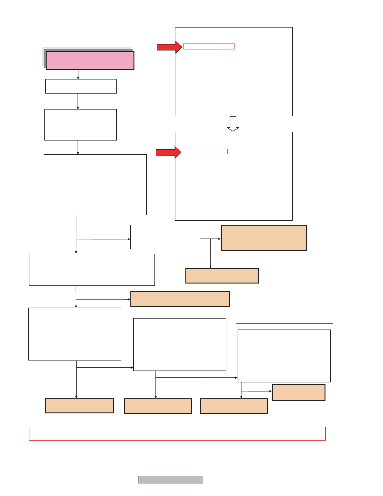
2 Alarm of fan error
Blinking in green (intervals of
0.5 seconds)
Disconnect the power cord.
Pressing the [MENU] key
of the product, Connect the
power cord. to cancel
alarming.
Is the fan running?
(Caution) When alarming is canceled,
[FAN MODE] of FAN SET
(P9/11) in the factory
adjustment menu
automatically moves from
[ENA] to [H], thus causing
the fan to run.
FAN SET
FAN MODE ENA CONT ENA —
FAN OFF/L — CONT UP —
FAN L/M — CONT TIME —
FAN M/H — UP STEP 2
SF SAVE 075 DOWN STEP 2
PLE SAVE 070 READ TIME 60
T ALM 095 TEMP LEVEL 1
RET TME 030
PLE TIME 001
T1 030 T2 025
T3 030 T4 — MODE 2
IC ERROR —
[MENU/ENTER] NEXT [EXIT] PREV 9/11
FAN SET
FAN MODE H CONT ENA —
FAN OFF/L CONT UP —
FAN L/M ——CONT TIME —
FAN M/H — UP STEP 2
SF SAVE 075 DOWN STEP 2
PLE SAVE 070 READ TIME 60
T ALM 095 TEMP LEVEL 1
RET TME 030
PLE TIME 001
T1 030 T2 025
T3 030 T4 — MODE 2
IC ERROR —
[MENU/ENTER] NEXT [EXIT] PREV 9/11
YES
NO
Is there a voltage output of 11.3Vdc for PD-4265,
11.2Vdc for PD-5065 respectively, at Pin 1 of
the FA, FB, and FC connectors?
NO
Is there a voltage output of
11.3Vdc for PD-4265, 11.2Vdc for
PD-5065 respectively, when the FA
connector is disconnected and the
mains power is turned ON?
YES
The FAN-A is fault.
YES
Is there a 3.3Vdc output
at Pin 3 of the FA and
FB, FC connectors?
The FAN-A/FAN-B/FAN-C is fault.
Is there a voltage output of
11.3Vdc for PD-4265,
11.2Vdc for PD-5065
respectively, when the FB connector
is disconnected and the mains
power is turned ON?
NO
YES
The FAN-B is fault.
YES
The MAIN PWB is fault.
The fan is out of order on the
side where a 3.3Vdc output is
generated.
NO
(Caution) The FAN-C and FC
Is there a voltage output of 11.3Vdc
for PD-4265, 11.2Vdc for PD-5065
respectively, when the FC connector
is disconnected and the mains
power is turned ON?
NO
NO
YES
The FAN-C is fault.
connectors are used
only for the 61XM3
Series.
The MAIN PWB
is fault.
(Caution) In the FAN MODE, [ENA] is automatically recovered when the main power is turned OFF→ON.
20
PD-5065

(3) Blinking in red (Alarm of temperature error)
Since the internal temperature is too high in the product, the temperature protector has been actuated. In such
a case, the following actions should be taken immediately:
1. Turn off the main power supply and pull out the power cord from the wall outlet.
2. Wait for about 60 minutes until the temperature in the main unit lowers.
3. Check whether the heat discharge port is covered with dust or the like. If yes, remove the clogging substance.
4. If the unit is used where the ambient temperature is high, it should be moved to an adequate place
(air temperature ranging from 5°C to 35°C).
PD-5065
21
(4) Alternation blinking in red and green (Alarm of PDP error)
(Caution) How to reset the alarming condition.
Pressing the [INPUT/EXIT] key of the product, turn on the main power supply
of the main unit. In this state, keep pressing the [Input Select] key for more
than 2 seconds until alarming is canceled. Make confirmation by the method
specified below.
Blinking in red and green
Disconnect the power cord.
Connect the power cord.
Is there alternation blinking
in red and green?
YES
Turn OFF the main power
supply.
With the [Menu] key of the
product kept pressed, turn
on the main power supply
to assume the
[Voltage Check Mode].
Is there a 3.3Vdc output at
Pin 3 of AD connector in
the MAIN PWB?
NO
Turn ON the main power
supply in the state that the
AD, PD, and PH connectors
are disconnected. In this
state, are there the outputs
of Vs (170Vdc), Vd (60Vdc),
and 5Vdc at the PD/PH
connectors as specified in
the table at right? In this
case, however, no images
are generate.
YES
NO
YES
NO
Normal
(Caution) When the main power supply is turned on with the
[Menu] key of the product kept pressed, it takes 30 seconds
more to assume the state of [blinking in red and green].
In this time period, the following voltage checks should be
carried out. If the state of [blinking in red and green] is
assumed during this checking, take actions of
[Alarm Canceling] and [Voltage Check Mode Setup] again.
The MAIN PWB is fault.
The Power unit is fault.
(Caution) The voltage values of Vd and Vs and also the connector
pin numbers can differ according to the PDP. The method of
checking these voltage values is obtainable from
[2. Adjustment of the power unit] in the method of adjustment
plus the table specified below.
Inch Vs Vd GND 5Vdc GND
42/50 PD-9pin PD-7pin PD-5pin PH-1pin PH-3pin
The PDP is fault.
(To the separate PDP service manual)
22
PD-5065
(5) Lighting in green, and then in red (Alarm of power voltage error)
Unlike [lighting in red] in the STANDBY mode, [lighting in green] continues for about 30 seconds without any output
of images and audio signals. Since then, the mode turns into [lighting in red].
Lighting in red
Disconnect the power cord.
Connect the power cord.
Turn On the power by remotecontrol.
Is the LED lit in red after it has been lit
in green for about 30 seconds?
YES
When the main power supply is turned on in
the state that the AD, PD, and PH connectors
are disconnected, are there the Vs (170Vdc)
and Vd (60Vdc) outputs at Pins 6-7to Pins
9-0 of the PD connector and a 5Vdc output
at Pins 1-2 of the PH connector?
In this case, is the LED not turned in red after
it has been lit in green for about 30 seconds?
At that time, however, no images are
generated.
NO
When the main power supply is turned on in
the state that the PA and PV connectors are
disconnected from one after another, is there a
12Vdc output at Pins 1-3 of the PA connector
or the 12Vdc and 6Vdc outputs at Pins 1 and
3-4 of the PV connector? In this case, is the
LED not turned in red after it has been lit in
green for about 30 seconds?
NO
YES
YES
Normal
(To the separate PDP service manual)
The PDP is fault.
(Caution) The voltage values of Vd and Vs
can differ according to the PDP. The
method of checking these voltage
values is obtainable from
[2. Adjustment of the power unit] in
the method of adjustment.
The MAIN PWB or the
AUDIO PWB is fault.
NO
Is there an output of 3.3Vdc available at Pins
1~3 and 2.5Vdc at Pins 7~9 in the state
that the PA and PV connectors are returned to
the former state, the main power is turned ON,
and the PN connector is disconnected? In this
case, however, this check must be finished in
30 seconds. Otherwise, there will be power
tripping on account of an alarm.
YES
The MAIN PWB is fault.
NO
PD-5065
The Power unit or the
PN connector is fault.
23
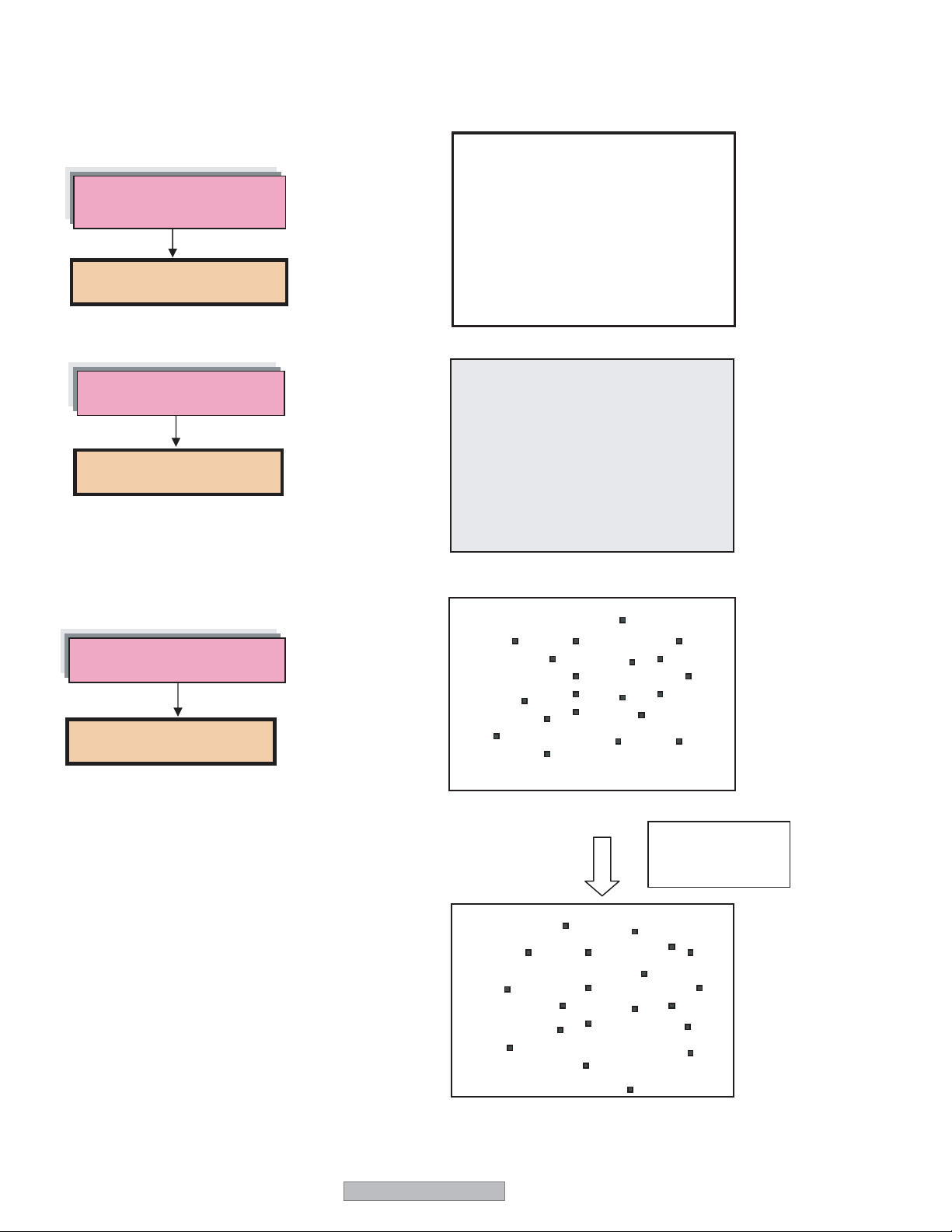
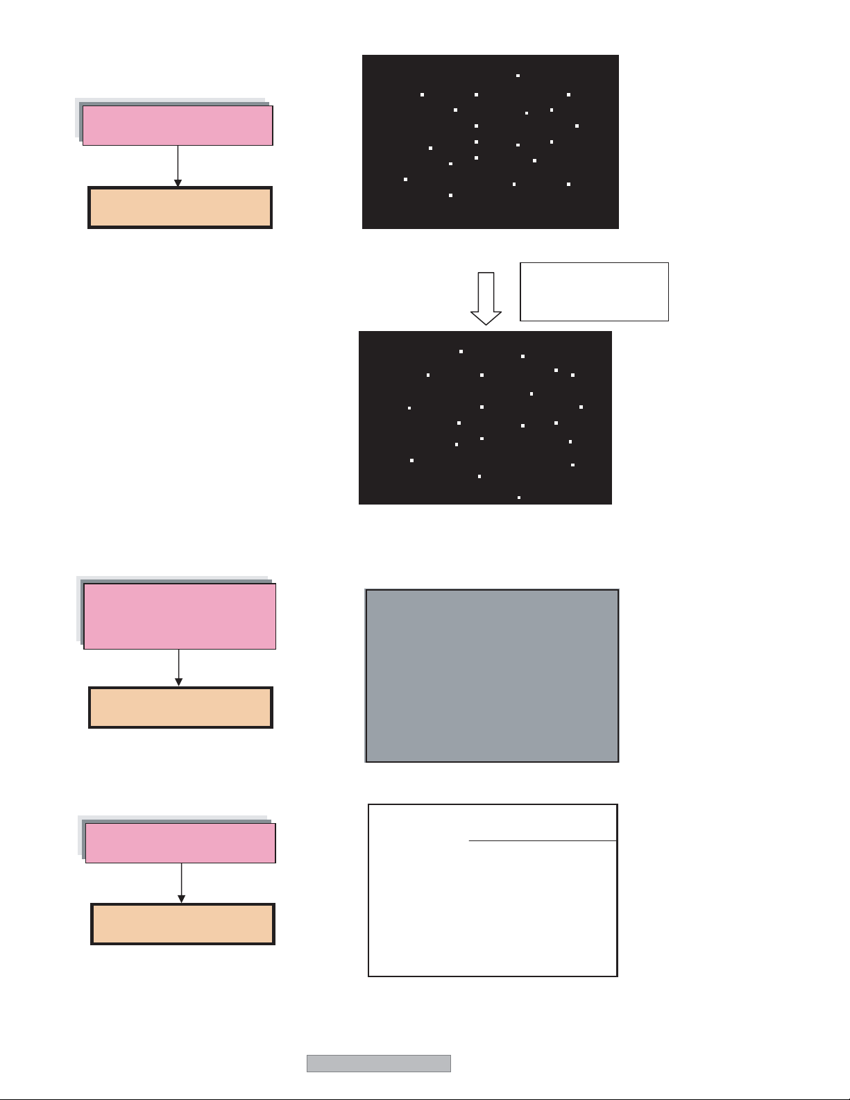
2. Image errors
(Caution) Typical abnormal images are shown below. All errors do not always fall on these error samples.
(1) Image burn and deterioration in brightness
Residual images are seen
without signal entry.
A
This is not a fault.
No signal
Deterioration in brightness
This is not a fault.
(2) Failure in writing
Failure in writing
The PDP is fault.
(To the separate PDP service manual)
All-white signal
All-white signal
Dot errors change
with no continuity.
24
All-white signal
PD-5065
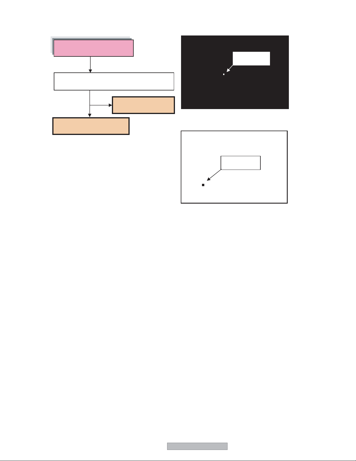
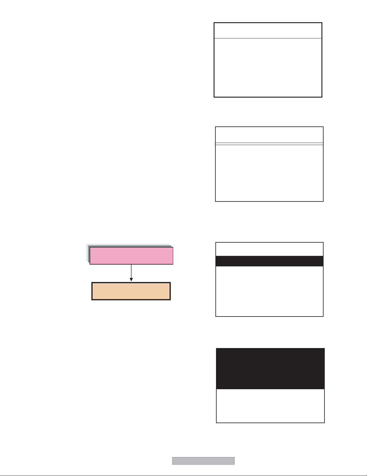
(3) Pixel defect
Pixel defect
Are there many defective pixels exceeding the
pixel defect standard?
Bright defect
NO
This is not a fault.
YES
The PDP is fault.
(To the separate PDP service manual)
(Fig. 1) All-Black Signal
Dark defect
(Fig. 2) All-White Signal
PD-5065
25
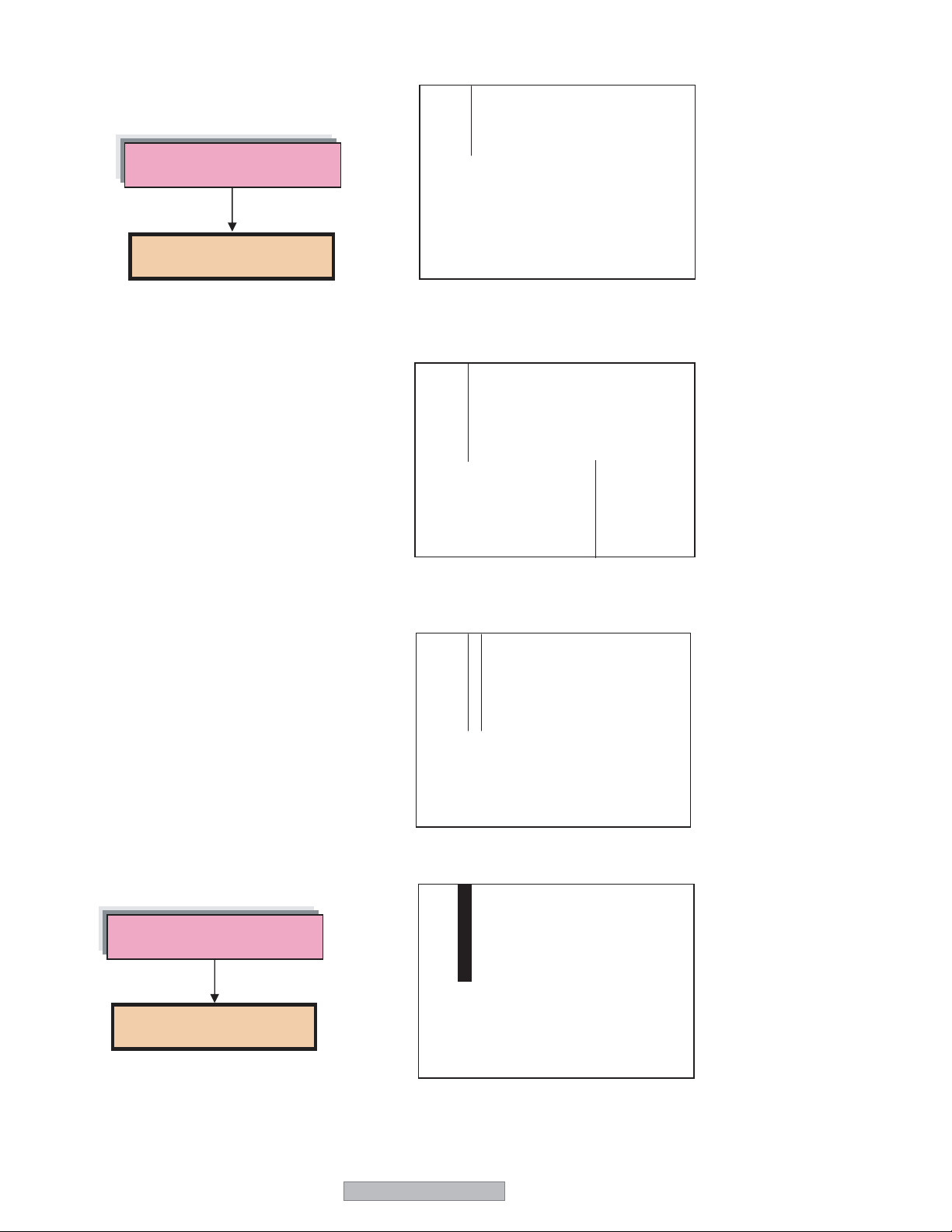
(4) Wrong lighting
Wrong lighting
The PDP is fault.
(To the separate PDP service manual)
All-black signal
Dot errors change
with no continuity.
All-black signal
(5) Dark images [Other than the deterioration in brightness as per (1) above]
The images are dark even with
an all-white input
The PDP is fault.
(To the separate PDP service manual)
All-white signal
(6) Defect in horizontal lines
Line defect
The PDP is fault.
(To the separate PDP service manual)
26
All-white signal
PD-5065
All-white signal
Defect in the block unit
The PDP is fault.
(To the separate PDP service manual)
All-white signal
All-white signal
PD-5065
All-white signal
27
(7) Defect in vertical lines
Defect in vertical lines
The PDP is fault.
(To the separate PDP service manual)
All-white signal
All-white signal
Block defect
The PDP is fault.
(To the separate PDP service manual)
28
All-white signal
All-white signal
PD-5065

All-white signal
All-white signal
PD-5065
29
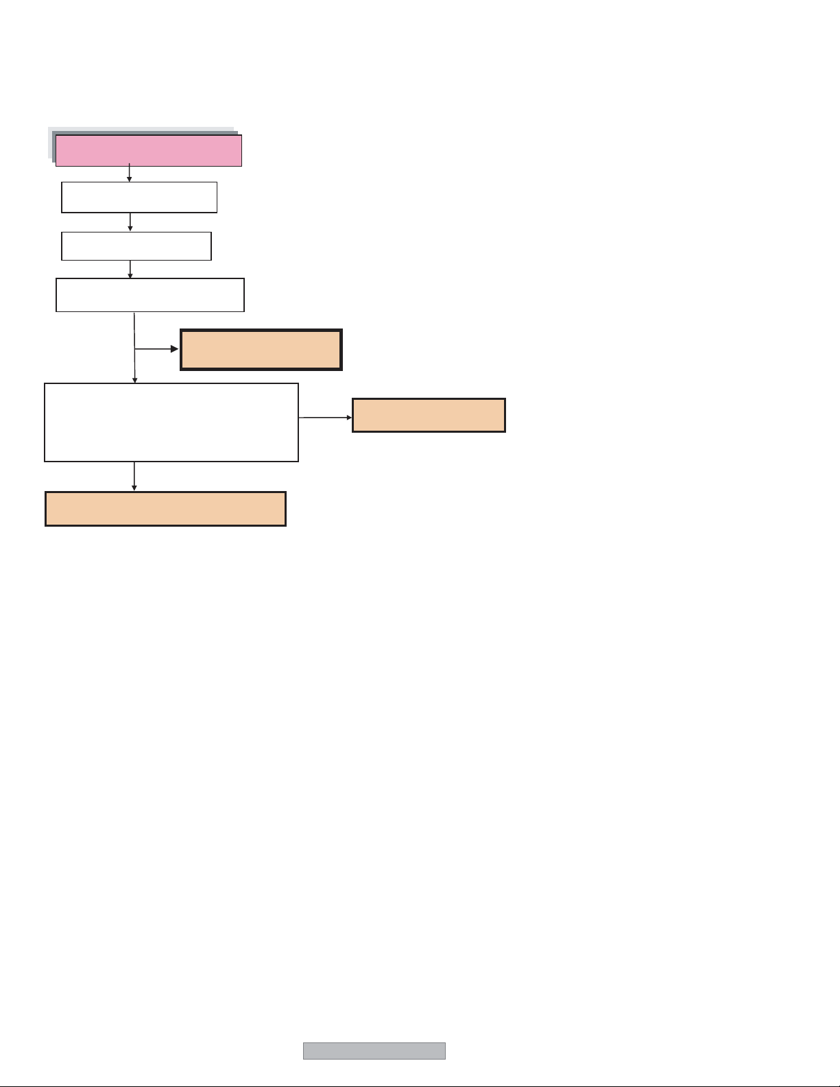
(8) No pictures [(Caution) The voltage outputs of Vs = 170V and Vd = 64V, 5Vdc are always generated, but the LED is
not flashing or lighting for alarming. However, the voltage values can differ according to the MODULE.]
No picture is displayed.
Disconnect the power cord.
Connect the power cord.
Does the priming glimpse?
NO
The PDP is fault.
YES
When the AD connector is disconnected, is
the LVDS signal normally output to each
pin of the AD connector? (For more details
of the signal, refer to the descriptions about
the connector pins.)
YES
The AD connector or the PDP is fault.
(To the separate PDP service manual)
(To the separate PDP service manual)
NO
The MAIN PWB is fault.
30
PD-5065
 Loading...