

Page 1
Building Air Conditioning Control System
Power supply unit
Model: PAC-SC50KUA
Contents
1. Safety precautions .................................................. 1
2. Product feature........................................................ 2
3. Installation ............................................................... 3
4. Wiring ...................................................................... 4
5. Allowable length of M-NET Transmission Lines ...... 6
Installation Manual
1. Specification .................................................... 2
2. Appearance ..................................................... 2
1. Parts prepared at site ...................................... 3
2. Installation space and the direction ................. 3
3. Unit installation ................................................ 4
1. Cover Removal and Installation ....................... 4
2. Power line ........................................................ 5
3. DC Power Supply and M-NET Transmission
Line .................................................................. 5
Before using the controller, please read this Installation Manual carefully to ensure
correct operation. Store this Installation Manual in a location that is easy to find.
Page 2

Page 3
This manual describes the installation of the PAC-SC50KUA Power supply unit and wiring to the central controller and the air conditioner units. For the information about how to install the central controller or the air conditioner units, see the installation manual for
them.
For your safety, first be sure to read 1 Safety precautions described below thoroughly and then install the PAC-SC50KUA correctly.
After reading this installation manual, keep it in a location that is easy to find, If the PAC-SC50KUA Power supply unit is going to be
operated by another person, make sure that this manual is given to them.
1 Safety precautions
Before installing this unit, make sure you read all the “Safety Precautions”.
The “Safety Precautions” provide very important points regarding safety. Make sure you follow them.
Symbols and Terms
WARNING Statements identify condition or practices that could result in personal injury or loss of life.
CAUTION Statements identify condition or practices that could result in damage to the unit or other property.
Specific Precautions
WARNING
Ask your dealer or technical representative to install.
Any deficiency cased by your own installation may result in
an electric shock and fire.
Install in a place which is strong enough to withstand
the weight of the unit.
Any lack of the strength may cause the unit to fall down,
resulting in a personal injury.
Wire and connect using the desired cables securely so
that any external force exerted on the cable is not imparted on to the terminal connections.
Imperfect connection and fixing may result in heating or fire.
Never modify or repair the unit by yourself.
Any deficiency caused by your modification or repair may
result in an electric shock or fire.
Consult with your distributor for repair.
Make sure that the unit is powered by a dedicated line.
Other appliances connected to the same line could cause
an overload.
Make sure that there is a main power switch.
A ready accessible breaker for power source line helps reduce the risk of electric shocks. Installation of a breaker is
mandatory in same area.
Ensure that installation work is done correctly following this installation manual.
Any deficiency caused by installation may result in an electric shock or fire.
All electrical work must be performed by a licensed technician, according to local regulations and the instructions given in this manual.
Any lack of electric circuit or any deficiency caused by installation may result in an electric shock or fire.
Do not move and re-install the unit yourself.
Any deficiency caused by installation may result in an electric shock or fire.
Ask your distributor or special vender for moving and installation.
This appliance must be earthed (grounded).
Make sure to install a protect earth(PE)/grounding line .
Do not connect the PE (grounding) line to gas or water
pipes, lightning conductors or telephone grounding lines.
Improper grounding may cause an electric shock.
Securely install the cover (panel) of the PAC-SC50KUA.
If the cover(panel) is not installed properly, dust or water
may enter the unit and fire or electric shock may result.
Do no install any place exposed to flammable gas
leakage.
Flammable gases that accumulates around the body of the
unit may caused an explosion.
Do not use in any special environment.
If use in any place exposed to oil (including machine oil),
steam and sulfuric gas may degrade performances significantly or damage the component parts.
Wire so that it wires do not received any tension.
Tension may caused wire breakage, heating or fire.
Do not wash with water.
Doing so may cause an electric shock or malfunction.
Do not install in any place at a temperature of more than
°C (104°F) or less than 0°C (32°F) or exposed to direct
40
sunlight.
Use only an earth leakage breaker and fuse of the specified capacity.
If no earth leakage breaker is installed, it may cause an electric shock.
Using fuse and wire or copper wire with too large a capacity
may cause a malfunction to the unit or fire.
CAUTION
Do not install in any steamy place such as bath room or
kitchen.
Avoid any place where moisture is condensed into dew.
Doing so may cause an electric shock or a malfunction.
Do not install in any place where acidic or alkaline solution or special spray or other similar substances are
used.
Doing so may cause an electric shock or malfunction.
Use standard wires in compliance with the current capacity.
A failure to do this may result in an electric leakage,
heating or fire.
Do not touch any PCB (Printed Circuit Board) with your
hand or tools. Do not allow dust to collect on the PCB.
Doing so may cause fire or an electric shock.
– 1 –
Page 4
2 Product feature
This unit supplies DC power to the central controller G-50A by means of the central controller system M-NET transmission line and DC
power line.
1. Specification
Source power requirement
Rated input
voltage and current
EU: ~220V - 240V ; 0.25A / 50Hz Single-phase
US: ~208V - 230V ; 0.25A / 60Hz Single-phase
Fuse:2.0A Time-delay type (IEC127-2 S.S.5)
Output voltage/current M-NET : DC24V 0.45A (Maximum loading)
DC power supply : DC12V 0.2A (Maximum loading)
Load capacity Number of the loading unit: G-50A Central Controller 1 unit
Environmental condition Temperature Operating range 0 to 40°C / 32 to 104°F
Storage range -20 to 60°C / -4 to 140°F
Humidity 30~90%RH (No condensation)
Dimensions 240 (H) ✕265 (W) ✕59.2 (D) mm / 9
1
Weight 2.3kg / 5
/8 lb
1
/2 (H) x 10 7/16 (W) x 2 3/8(D) in
Installation Environment In the control panel box (indoor)
*This unit is installed and used in a business office or equivalent environment.
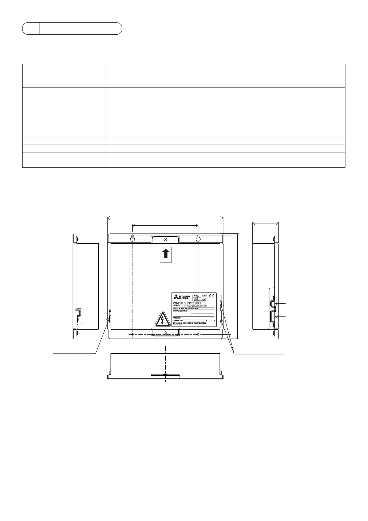
2. Appearance
7
265 (10
150 (5 15/16)
/16)
59.2 (2
3
/8)
Cable fixture
TB1
UP
)
)
8
2
/
/
7
1
225 (8
240 (9
TB3
EU:~220V-240V; 0.25A 50Hz
US:~208V-230V; 0.25A 60Hz
2.3 kg / 5 1/8 lb
TB2
Cable fixture
unit: mm (in)
– 2 –
Page 5

3 Installation
1. Parts prepared at site
Please prepare the following parts before installation of the unit.
Preparation parts
Unit fixing screw
Power cable/
Protective earth cable
(Ground cable)
Main power switch
(Circuit breaker)
Transmission cable
DC power cable
* Use a breaker with a contact distance of 3mm (1/8 in) or more.
M4 screw × 4pcs
Use sheathed vinyl cord or wire.
Wire type: Wire should not be lighter than ordinary PVC sheathed flexible cord IEC 60227
(designation 60227 IEC 53)
Wire size: 0.75mm
2
to 2mm2 (AWG18 to 14)
Qty.:1pc
Type: 250VAC, Single-phase 3A
Type of the cable; Sheathed vinyl cords or cable which comply with the following specifications or
equivalent.
• CPEVS φ1.2mm to φ1.6mm
• CVVS 1.25mm
2
to 2mm2 (AWG16 to 14)
* CPEV; PE insulated PVC jacketed shielded communication cable
* CVVS; PVC insulated PVC jacketed shielded control cable
PE: Polyethylene PVC: Polyvinyl chloride
Cable length: Please refer to section 5 Allowable length of M-NET transmission line
The DC power cable should comply with both local standards as well as the power requirement of
the unit.
2
Recommended type: 0.75mm
to 2mm2 (AWG18 to 14)
Cable length: Within 10m (32 ft)
Specification
2. Installation space and the direction
PAC-SC50KUA Power supply unit is not waterproof.
PAC-SC50KUA shall be installed in a control panel box (steel : thickness 1mm (3/64 in) or more).
Please prepare the control panel box in consideration with installation space as shown in the Fig.3-1.
(Install in an area capable of withstanding a 2.3 kg (5 1/8 lb) load.)
The unit shall be also installed in vertical direction only indicated by arrow making on the cover as shown in the Fig.3-1.
20 (13/16)
20 (13/16)
UP
EU:~220V-240V; 0.25A 50Hz
US:~208V-230V; 0.25A 60Hz
2.3 kg / 5 1/8 lb
20 (13/16)
20 (13/16)
unit: mm (in)
Fig.3-1
– 3 –
Page 6

3. Unit installation
Fix the unit to the control panel box using M4 screw as shown in the Fig.3-2.
CAUTION
The unit should be fixed with 4 positions to prevent from unit falling down.
UP
EU:~220V-240V; 0.25A 50Hz
US:~208V-230V; 0.25A 60Hz
2.3 kg / 5 1/8 lb
M4
Fig.3-2
4 Wiring
WARNING
• All electric work must be performed according to local regulations.
Improper electrical work may result in electric shock or fire.
• Be sure to shut off the power source of the unit and the all other unit to be connected to the power supply unit before wiring.
CAUTION
Do not connect the AC power line to the M-NET and POWER (DC12V) terminal blocks of this device. Otherwise, the unit may fail.
1. Cover Removal and Installation
When removing the cover, remove the 2 mounting screws and remove the cover.
When installing the cover, install the cover by tightening the 2 screws.
UP
Fig.4-1
– 4 –
EU:~220V-240V; 0.25A 50Hz
US:~208V-230V; 0.25A 60Hz
2.3 kg / 5 1/8 lb
Page 7

2. Power line
Wire the power cable and protective earth cable (grounding cable) to L/L1,N/L2 and the earth line (grounding line) terminals on the TB1
as shown in the Fig.4-2.
24V
Power source
EU:~220-240V 50Hz
US:~208-230V 60Hz
*US: USA and
Canada
Ground
Circuit breaker
Power cable
Protective earth cable
(Grounding cable)
Fix the power line
Power cable
R
TB1
EU/US
NL
(L/L1)
(N/L2)
12V
GND
12VDC
T B 2 T B 3
ABS
Power line terminal
EU : ~220V-240V 50Hz
US : ~208V-230V 60Hz
L/L1 N/L2
Protective
earth cable
TB1
(Grounding cable)
*EU shows L/N and the US shows L1/L2.
Fig.4-2
3. DC Power Supply and M-NET Transmission Line
The DC power line and M-NET transmission line connect as shown in Fig. 4-3. The DC power line has a 12VDC and a GND polarity.
Connect it to the terminals in accordance with the polarity. Connect the M-NET transmission line to the A, B (non-polarity) and S
(shield) terminal block.
DC power supply line terminal
Fix the power line.
R
M-NET transmission
TB3
NL
TB2
line terminal
Within 10m
24V
12V
GND
12VDC
T B 2 T B 3
ABS
DC power supply line
(DC12V) ❈Polarized
Outdoor
Unit
TB7
M-NET transmission line
(Centralized control line)
Central controller
Controller rear surface
M-NET
POWER
GND
12VDC
SBA
TB3
TB2
Function earthing(grounding)
DC 12V power supply line (Polarity)
Shield
M-NET transmission A,B line
(Non-polarity DC24V)
Fig.4-3
– 5 –
GND12VDC
SBA
DC 12V power supply line
(Polarity)
12VDC : +12V, GND : 0V
Function earthing(grounding)
Page 8

CAUTION
• Both of PAC-SC50KUA and Outdoor unit can supply DC power to the M-NET transmission line.
Set the outdoor unit central control system transmission line power supply to the factory setting CN41 (no supply). For further
details, refer to the installation manual of the outdoor unit. Not doing so may cause unit failure or fire.
NOTE
The shied wire of M-NET transmission line shall be grounded by one point similar to earthing (grounding) method.
The shield wire shall be connected to the S terminal of only one unit on the common transmission line.
After connection for the each cable, fasten each cable with the cable fixture.
5 Allowable length of M-NET Transmission Lines
• Maximum length of M-NET transmission 500m/1640 ft *1
• Maximum power feeding length
NOTE
* 1: Not including the remote control cables up to 10m (32 ft) in length. If the remote control cable exceeds 10m (32 ft), the excess
must be added to the total length in order to avoid exceeding the maximum length.
Example
Central
controller
DC Power
supply
(DC12V)
Length: max.10m (32 ft)
L2 L3 L4
L1
Power
supply
unit
200m/656 ft
Outdoor
unit
L5
r1
r2
Indoor Indoor
r4
Remote controller
Indoor
r3
Indoor
r5
Indoor Indoor
r6
r7
M-NET transmission line
(Centralized control line)
M-NET transmission line
(Indoor control line)
Outdoor
r8
Remote controller
Indoor
Indoor Indoor
1) Maximum length of M-NET transmission
1 L2+L3+L4+r1+r2+r3 (r4)
2 L2+L3+L4+r1+r5
3 L2+L3+L5+r6+r7 (r8)
4r3 (r4) +r2+r1+L4+L5+r6+r7 (r8)
5 r5+r1+L4+L5+r6+r7 (r8)
500m/1640 ft
500m/1640 ft
500m/1640 ft
500m/1640 ft
500m/1640 ft
2) Maximum power feeding length for the indoor control line
1 r1+r2+r3 (r4)
2 r1+r5
200m/656 ft
200m/656 ft
3) Maximum power feeding length for the centralized control line
1 L1 +L2
2 L1 +L3+L4 (L5)
200m/656 ft
200m/656 ft
NOTE
If the remote control cable (r4,r8) do not exceed 10m (32 ft) in length, the length for r4,r8 may not consider to the total length.
– 6 –
Page 9

Page 10

Page 11

Page 12

This product is designed and intended for use in the residential,
commercial and light -industrial environment.
The product at hand is
based on the following
EU regulations:
NOTE:
This equipment has been tested and found to comply with the limits for a Class B digital device, pursuant to
Part 15 of the FCC Rules. These limits are designed to provide resonable protection against harmful interference in a residential installation. This equipment generates, uses and can radiate radio frequency energy and,
if not installed and used in accordance with the instructions, may cause harmful interference to radio communications.
However, there is no quarantee that interference will not occur in a particular installation.
If this equipment does cause harmful interference to radio or television reception, which can be determined
by turning the equipment off and on, the user is encouraged to try to correct the interference by one or more
of the following measures:
- Reorient or relocate the receiving antenna.
- Increase the separation between the equipment and receiver.
- Connect the equipment into an outlet on a circuit different from that to which the receiver is connected.
- Consult the dealer or an experienced radio / TV technician for help.
• Low Voltage Directive 73/23/EEC
• Electromagnetic Compatibility Directive 89/
336/EEC
WT03938X01
HEAD OFFICE: MITSUBISHI DENKI BLDG. , 2-2-3, MARUNOUCHI, CHIYODA-KU, TOKYO 100-8310, JAPAN
Printed in Japan
Recycled Paper
 Loading...