

Page 1
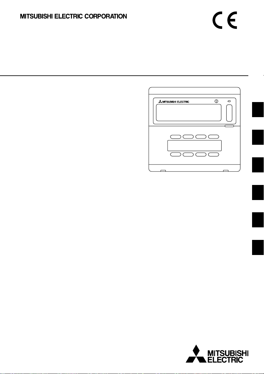
Mitsubishi Electric Building
Air Conditioning Control System
Group remote controller
PAC-SC30GRA
CENTRALLY CONTROLLED
CHECK
COLLECTIVE
GROUP
ADDRESS
ON
OFF
˚C
NOT AVAILABLE
GROUP
˚C
FILTER
CHECK MODE
TEST RUN
ON/OFF
GB
D
F
NL
I
E
INSTRUCTION BOOK
Carefully read this book before use. It is recommended to safe keep this book for future reference.
ANWEISUNGSHANDBUCH
Vor Benutzung der Anlage dieses Buch sorgfältig durchlesen. Es wird empfohlen, dieses Buch zum Nachschlagen an einem sicheren Ort aufzubewahren.
MANUEL D’UTILISATION
Lire attentivement le présent manuel avant toute utilisation et le conserver dans un endroit sûr pour pouvoir le consulter ultérieurement.
INSTRUCTIEHANDLEIDING
Lees deze handleiding aandachtig door voordat u het apparaat in gebruik neemt. Het wordt aanger aden om deze handleiding zorgvuldig te bewaren om later, indien nodig, te raadplegen.
LIBRETTO ISTRUZIONI
Leggere attentamente questo libretto prima dell’uso. Si raccomanda di tenerlo in un luogo sicuro per ogni futura necessità.
LIBRO DE INSTRUCCIONES
Lea cuidadosamente este libro antes de usar el temporizador. Le recomendamos que guarde el libro en lugar seguro en previsión de consultas futuras.
Page 2
CONTENTS Page
1. Safety precautions ................................................................................................ 2
2. Functions .............................................................................................................. 4
3. The names of indicators and their functions ......................................................... 6
4. Operations ............................................................................................................ 8
5. Filter sign reset ................................................................................................... 12
6. When malfunction occurred ................................................................................ 12
7. Initial settings ...................................................................................................... 13
8. Functions during start-up and servicing ............................................................. 24
9. Specifications ..................................................................................................... 27
Symbols and Terms ..................................................................................... 2
Specific Precautions.................................................................................... 3
4-1. Operation settings by group ........................................................................ 8
4-2. Collective operation settings ....................................................................... 9
4-3. Adjusting each function ............................................................................. 10
7-1. Setting the master controller ..................................................................... 13
7-1-1. Group settings ............................................................................. 14
7-1-2. Interlocked setting........................................................................ 18
7-1-3. Canceling the initial setting mode ................................................ 23
7-1-4. Collective deletion........................................................................ 23
7-2. Setting the slave controller........................................................................ 23
8-1. Self-diagnosis............................................................................................ 24
8-2. Malfunction history monitoring function ..................................................... 26
Specifications for this equipment............................................................... 27
1. Safety precautions
Please take a moment to review these safety precaution. They are provided for your protection and to
prevent damage to the controller.
This safety information applies to all operators and service personnel.
After you have read this manual, always observe the procedures described in the explanations and store
it with the installation manual in a location that is easy to find. If the controller is going to be operated by
another person, make sure that this manual is given to him or her.
Symbols and Terms
WARNING Statements identify condition or practices that could result in personal injury or loss of life.
CAUTION
Statements identify condition or practices that could result in damage to the controller or other
property.
2
Page 3
Specific Precautions
WARNING
■ Ask your dealer or technical representative to install.
• If incorrect installation is done by a customer, it may cause an electric shock, fire, etc.
■ Securely install in a place which can withstand the weight of the controller.
• If it is not enough, the controller may drop and cause an injury.
■ Make sure that the controller is connected to a rated power supply.
• If the controller is not connected to a rated power supply, it may cause a fire or damage to the controller.
■ Never remove the cover during operation.
• Touching the charging parts of the controller may cause severe burns or other personal injury.
■ Stop the operation if any malfunction occurs.
• If malfunction occures (burning smell, etc.) stop the operation and turn off the power supply. Contact the your
dealer or technical representative immediate. If the controller continues to operate after a malfunction occurs, this
may cause damage, electric shock or fire.
■ Do not move and re-install the controller by yourself.
• If installation is incorrect, it may cause an electric shock, fire, etc. Ask your dealer or technical representative.
■ Contact your dealer if the controller will not be used any more or will be scrapped.
■ Do not remodel or repair by yourself.
• If the controller is remodeled or repair is not correct, it may cause an electric shock, fire, etc.
Consult your dealer if repair are necessary.
■ Stop the operation immediately and notify the your dealer if an error code is displayed or malfunction occurs.
• Fire or damage may cause it the controller is operated in this condition.
CAUTION
■ Do not install the controller in a place where inflammable gas could leak.
• If gas leaks and collects around the controller, it may cause a fire or explosion.
■ Do not wash the controller with water.
• It may cause an electric shock or malfunction.
■ Do not touch the switch with wet hands.
• It may cause an electric shock.
■ Do not use the controller for special applications.
• This product is designed for use with the MITSUBISHI ELECTRIC BUILDING AIR CONDITIONING CONTROL
SYSTEM. Do not use the system for other air condition management operation or applications. It may cause
malfunctions.
■ Do not apply insecticide or flammable sprays to the controller.
• Do not place flammable spray near the controller and make sure it does not blow directly on the controller as this
may cause in fire.
■ Do not use the controller in special environments.
• The performance may be reduce or parts may be damaged if the controller is used in locations subject to large
quantities of oil (including machine oil), steam, sulfide gas.
■ Do not touch the switches with sharp objects.
• It may cause an electric shock or malfunction.
■ Operate the controller within the specified temperature range.
• Observe the specified temperature range when operating the controller. If the controller is used outside the
specified temperature range, it may cause serious damage. Be sure to check the operation temperature range in
the operation manual.
■ Do not pull or twist the transmission line.
• It may cause a fire or malfunction.
■ Do not dismantle the unit.
• It is dangerous to touch the internal circuit board. It may cause a fire or malfunction.
■ Do not clean the unit using benzene, thinner or other chemicals.
• It may cause discoloration or other damage. If the unit should become particularly dirty, apply a mild cleaner that
has been diluted with water to a soft cloth and wipe the unit clean. Be sure to wipe away any residual moisture
with a dry cloth.
GB
3
Page 4
2. Functions
• This unit can control a maximum of 16 air conditioner units. The operation listed below are also
possible.
<List of group remote controller functions>
Item Specification
ON/OFF ON/OFF operations for the collective or each group.
Operation mode Switches between cool/dry/fan/auto/heat for the collectiv e or each group.
Fan speed
Temperature setting
Opera-
tions
Horizontal blow
Air direction/swing Operates the vertical fan and swing fan for the collective or each group .
Ventilation operation
Timer operation
Filter reset
Collective operation The overall status lamps display condition of the collective status.
User operating function
Monitor-
Opera-
Monitor
System
Initial setting functions
Each group operation
Operation mode
Fan speed
Temperature settings
Horizontal blow
Air direction/swing
ing
Ventilation operation
Timer operation
Filter sign
Prohibition
Malfunction
Group settings
tions
Interlocked settings
Malfunction history Displays the history of the ten malfunctions.
Master system
controller/slave
system controller (*1)
Group remote
controller’s address
Switches between high /low for the collective or each group (switches
the fan speed through four stages from 1 to 4)
Sets the temperature for the collective or each group.
Range of
temperature settings
Starts and stops horizontal blow operations for the collective or each
group.
Switches the interlocked ventilation unit between stop/high/low for the
collective or each group.
Switches between activating and suspending scheduled oper ations that
use a program timer (sold separately) for the collective or each group.
Resets the filter sign after the filter has been cleaned for the collectiv e or
each group.
Liquid crystal display
Displays the unit address of the malfunction unit and the error code on
the liquid crystal display
Performs the group settings for the unit (indoor unit, remote controller,
slave system controller)
Perf orms the interlocked settings f or fresh masters and other v entilation
unit.
Master and slave settings for the system controller.
Address setting for the group remote controller.
Cool/Dry operations : 19 °C to 30 °C
Heat operations : 17 °C to 28 °C
Auto operations : 19 °C to 28 °C
4
Page 5
Item Specification
Indoor unit Maximum 16 (maximum 8 groups)
Number of indoor
units in one group
Number
of control
System control
Number of remote
controllers in one group
Number of system 0 to 4 (including the number of remote controller in one group)
unit
controllers in one group 0 to 3 for which have one remote controller.
Number of indoor units
interlocked with one
ventilation unit.
0 to 16
0 to 2
0 to 16 (some type of ventilation unit can be only operate when interlocked to a maximum of 9 units)
*1 Master system controllers and slave system controller
Management range of
PAC-SC30GRA
Unit
Management range of the
master system controller
Management range
of PAC-SC30GRA
Unit Unit
GB
When using a system consisting only of PACSC30GRA.
PAC-SC30GRA is set as the master system
controller. In this case, the group settings are
performed with PAC-SC30GRA.
When using a system where PAC-SC30GRA is
controller by a different system controller.
PAC-SC30GRA is set as the slave system
controller. In this case, the group settings are
not performed with PAC-SC30GRA.
NOTE: It is not possible to set the master and slave settings with more than one group remote
controller and control the same groups. Also, the groups listed below cannot be set.
• Unit group which are not under the management of the master controller and are managed by the
slave system controller.
Master system
controller
Group Group
Slave system
controller
Group
• A common group is managed by more than two master controllers.
Master system
controller 1
Group
Master system
controller 2
GroupGroup
• A slave system controller which exceeds the management range of the master system controller of
two or more.
Master system
controller 1
Slave system controller
Master system
controller 2
Group GroupGroupGroup
5
Page 6
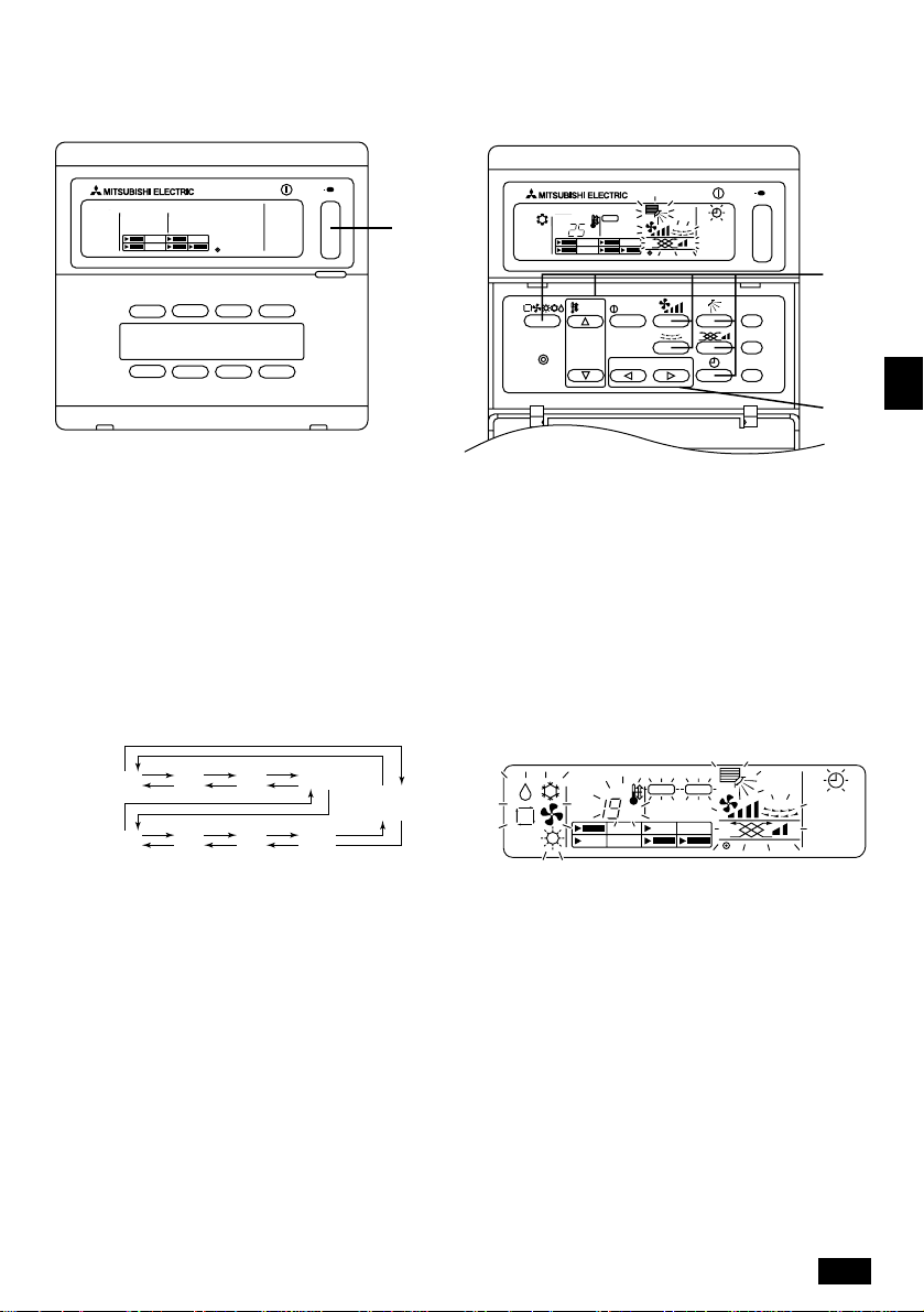
3. The names of indicators and their functions
DEFGHI
C
B
A
CENTRALLY CONTROLLED
COLLECTIVE
GROUP
ON
˚C
2 3456
1
TEMP.
GROUP
REMOTE CONTROLLER
PAC-SC30GRA
A COLLECTIVE SETTINGS/INDIVIDUAL GROUP
SETTINGS DISPLAY:
COLLECTIVE is displayed when entering the same
settings for multiple groups.
GROUP is displayed when entering varying settings for
individual groups.
B OPERATION MODE DISPLAY:
Displays the current operating mode.
C CENTRALLY CONTROLLED DISPLAY:
Indicates when operation of group remote controller is
prohibited by the master controller.
D TEMPERATURE SETTING DISPLAY:
Displays the current temperature setting.
E ON/OFF DISPLAY FOR INDIVIDUAL GROUPS:
Displays whether a group’s operations have been
stopped by showing a “s” mark in the operation status
display for each individual group.
F FAN SPEED DISPLAY:
Displays the current fan speed.
G AIR DIRECTION DISPLAY:
Displays the current direction of airflow.
H ROOM TEMPERA TURE DISPLAY :
Indicates the room temperature of the group currently
being displayed (will blink when the temperature is
outside the range of 8°C to 39°C).
I HORIZONTAL BLOW DISPLAY:
Displays the operations of the horizontal blow. Not
displayed when operations are stopped.
OFF
ON/OFF
NOT AVAILABLE
GROUP
ON/OFF
˚C
FILTER
FILTER
CHECK
TEST RUN
J
K
78
9
0A
J TIMER OPERATION DISPLAY:
Displayed when a PROGRAM TIMER (sold separately)
is installed and the TIMER MODE is set.
K FILTER SIGN DISPLAY:
Blinks when the filter requires cleaning. Also the
GROUP SELECTION DISPLAY “s” of the specified
group will blink.
L OPERATIONAL STATUS DISPLAY BY GROUP:
ON: Run OFF: Stop BLINKING: Malfunction
M GROUP SELECTION DIPLAY: s
Displays the position of the selected group. All
registered groups are displayed on the collective
operation setting screen.
N VENTILATION DISPLAY:
Displays the operating condition of the ventilation unit
(if a ventilation unit has been installed).
O NOT AVAILABLE DISPLAY:
Blinked together with the relevant function when a
function switch has been pressed for a unit that is not
equipped with the function.
P OVERALL STATUS LAMP:
The lamp indicates the unit operation condition.
ON: One or more group(s) run.
OFF: All groups stopped. BLINKING: Malfunction.
6
Page 7
M
L
CENTRALLY CONTROLLED
COLLECTIVE
GROUP
ON/OFF
ON
OFF
˚C
GROUP
NOT AVAILABLE
˚C
FILTER
P
N
O
B
GB
C
1 OPERATION MODE SWITCH:
Used to switch between Cool/Dry/Fan/Auto/Heat.
2 TEMPERATURE SETTING SWITCH:
Used for changing the temperature setting. Setting
changes are possible in increments of 1°C.
3 ON/OFF SWITCH:
Used to switch between ON/OFF for the group
indicated on the group selection display.
4 FAN SPEED SWITCH:
Used to switch fan speeds.
5 AIR DIRECTION SETTING SWITCH:
Used to adjust the vertical direction of the blow.
6 FILTER SIGN RESET SWITCH:
Used to reset the filter sign.
7 HORIZONTAL BLOW SWITCH:
Used to switch between start and stop for the
horizontal blow.
8 VENTILATION SETTING SWITCH:
Used for changing the operation settings of the
ventilation unit (if a ventilation unit has been installed).
Possible changes to the operation settings of the
ventilation unit include OFF/ON (low) or ON (high).
It is possible to operate only the ventilation units by
pressing this switch when the air-conditioners are not
operating.
9 CHECK/TEST RUN SWITCH:
Used only during inspections and test run operations.
Not to be used during normal operations.
0 GROUP SELECT SWITCH:
Used to call out the group and collective operation
setting screens to perform the various settings.
G 1
G 2 G 3 G 4
G 5 G 6 G 7 G 8
COLLECTIVE OPERATION
SETTING SCREEN
“Group” is abbreviated as “G”.
A EXTERNAL TIMER SWITCH:
Allows you to select the TIMER MODE when a
PROGRAM TIMER (sold separately) has been
installed.
B COLLECTIVE ON/OFF SWITCH:
Allows you to operate and turn off the air conditioners
for all groups at once.
All groups will commence operations when operations
for all groups are stopped.
Operations for all groups stopped when one or more
groups are operating.
C ON/OFF SWITCH BY GROUP:
Run and stop operations by each group.
7
Page 8
4. Operations
4-1. Operation settings by group
(1) With the cover closed: (2) With the cover open:
CENTRALLY CONTROLLED
CHECK
COLLECTIVE
GROUP
ADDRESS
ON/OFF
ON
˚C
˚C
OFF
GROUP
FILTER
CHECK MODE
TEST RUN
NOT AVAILABLE
CENTRALLY CONTROLLED
CHECK
COLLECTIVE
GROUP
ADDRESS
TEMP.
ON
OFF
˚C
NOT AVAILABLE
ON/OFF
1
GROUP
REMOTE CONTROLLER
PAC-SC30GRA
GROUP
ON/OFF
˚C
GROUP
FILTER
CHECK MODE
TEST RUN
FILTER
CHECK
TEST RUN
(1) With the cover closed:
1 The start and stop functions of the air conditioners for each group can be controlled using the
ON/OFF switch by group.
(2) With the cover open:
1 Use the GROUP select switch to call the group that you want to set. (GROUP SELECTION
DISPLAY: The position of the “s” will change. Groups of air conditioners that ha ve not been
registered will be skipped.)
G 1
G 2 G 3 G 4
COLLECTIVE OPERATION
SETTING SCREEN
2
1
G 5 G 6 G 7 G 8
“Group” is abbreviated as “G”.
2 Controlling the items that you want to adjust
• If the selected group is not in operation, press the ON/OFF switch to start operation.
• Press the switch that you want to adjust (OPERATION MODE, TEMPERATURE SETTING,
FAN SPEED, AIR DIRECTION SETTING, HORIZONTAL BLOW, VENTILATION SETTING and
EXTERNAL TIMER SETTINGS).
(For detailed explanations on how to adjust each feature, refer to 4-3.)
• If the registered group contains air conditioners that are not equipped with the FAN SPEED,
AIR DIRECTION SETTING, HORIZONTAL BLOW, VENTILATION SETTING and EXTERNAL
TIMER SETTINGS, the message “NOT AVAILABLE” will blink to indicate that the setting is not
supported.
8
Page 9
4-2. Collective operation settings
(1) With the cover closed: (2) With the cover open:
CENTRALLY CONTROLLED
CHECK
COLLECTIVE
GROUP
ADDRESS
ON/OFF
ON
˚C
˚C
OFF
GROUP
FILTER
NOT AVAILABLE
CHECK MODE
TEST RUN
1
CENTRALLY CONTROLLED
CHECK
COLLECTIVE
GROUP
GROUP
REMOTE CONTROLLER
PAC-SC30GRA
ADDRESS
TEMP.
ON
OFF
˚C
NOT AVAILABLE
ON/OFF
GROUP
ON/OFF
˚C
GROUP
FILTER
CHECK MODE
TEST RUN
FILTER
CHECK
TEST RUN
(1) With the cover closed:
1 The start and stop functions of the air conditioners for all groups can be controlled using the
collective ON/OFF switch. (This collective ON/OFF function can be operated when the UPPER
PANEL is open as well.)
(2) With the cover open:
1 Call the COLLECTIVE OPERATION SETTING SCREEN using the GROUP select switch (the
screen in which all indicators are blinking).
[COLLECTIVE OPERATION SETTING SCREEN]
G 1
G 2 G 3 G 4
G 5 G 6 G 7 G 8
COLLECTIVE OPERATION
SETTING SCREEN
CENTRALLY CONTROLLED
CHECK
COLLECTIVE
GROUP
ADDRESS
ON
OFF
˚C
NOT AVAILABLE
“Group” is abbreviated as “G”.
GROUP
˚C
2
1
FILTER
CHECK MODE
TEST RUN
GB
2 Controlling the items that you want to adjust
• Press the switch that you want to adjust (OPERATION MODE, TEMPERATURE SETTING,
FAN SPEED, AIR DIRECTION SETTING, HORIZONTAL BLOW, VENTILATION SETTING and
EXTERNAL TIMER SETTINGS).
(For detailed explanations on how to adjust each feature, refer to 4-3.)
• Indicators will stop blinking but will remain lit as the settings are entered for all groups.
• If you do not want to adjust a particular setting for all groups, leave it as is (so that it continues
to blink). The previous setting that was used will continue to be enabled.
9
Page 10

4-3. Adjusting each function
The following section describes the operation of the switches for the OPERATION MODE, TEMPERATURE SETTING, FAN SPEED, AIR DIRECTION SETTING, HORIZONTAL BLOW, VENTILATION
SETTING and EXTERNAL TIMER SETTINGS.
If your air conditioner is not equipped with FAN SPEED, AIR DIRECTION SETTING, HORIZONTAL
BLOW, VENTILATION SETTING and EXTERNAL TIMER SETTINGS or a PROGRAM TIMER (sold
separately), the “NOT AVAILABLE” indicator will blink when the switches for these functions are
operated and the operation will not be performed.
However, “NOT AVAILABLE” does not appear on the COLLECTIVE OPERATION SETTING
SCREEN.
If “CENTRALLY CONTROLLED” blinks when the each switch is operated, the message indicates
that the operation is prohibited by the master controller.
All of the blinking items in the COLLECTIVE OPERATION SETTING SCREEN indicate items that
can be adjusted. After the items are adjusted they will stop blinking but will remain lit and those
adjustments will be applied to all groups.
(1) Operation mode
1 Press the operation mode switch.
• The operation mode will switch between Cool ( ) → Dry ( ) → Fan ( ) → <Auto ( )> →
<Heat ( )> whenever the operation mode switch is pressed. The operation modes
enclosed in parenthesis (< >) will not be displayed if the indoor units registered in the various
groups are not equipped with these modes.
(2) Temperature adjustment
1 Press either of the or temperature setting switch.
• The temperature setting will be amended by 1 °C when either of the or tempera-
ture setting switch are pressed. The setting will change by 1 °C in a continuous stream if
pressure is kept on these switches.
• The room temperature can be set within the following ranges.
• The room temperature cannot be set for Fan operations.
• Although the temperature range can be set between 19 to 30 °C regardless of the operation
mode on the collective operation setting screen, the actual temperature setting will be based on
the operation mode for each group.
Cool/Dry operations: 19 °C to 30 °C
Heat operations: 17 °C to 28 °C
Auto operations: 19 °C to 28 °C
(3) Fan speed adjustment
1 Press the fan speed switch.
• The fan speed settings will differ depending on the type of indoor unit.
Fan speed
2-stage
4-stage
Low Medium 2 Medium 1 High
Remote controller display
The fan speed will change whenever the fan speed switch is pressed.
10
Page 11

(4) Horizontal blow
1 Press the horizontal blow switch.
• The horizontal blow are operated and stopped whenever the horizontal blow switch is
pressed.
[Display example] <When the horizontal blow <When the horizontal blow
are operating> are not operating>
↔
Interchangeable display No display
(5) Air direction
1 Press the air direction switch.
• The direction of the fan will change whenever the air direction setting switch is pressed.
12345
• Only I - IV will be displayed without V if the indoor unit is not equipped with the swing function.
(6) Ventilation setting
1 Press the ventilation setting switch
• The ventilation unit is operated whenever the ventilation setting switch is pressed.
Off Low High
[Display example]
<With low ventilation> <With high ventilation>
• Once the interlocked operations between the indoor unit and the ventilation unit have been set
once, the same operations can be repeated simply by pressing the
ON/OFF
switch.
• The ventilation setting switch is valid even when the air-conditioner is not operating to
enable only the ventilation unit to be used. (The
ON/OFF
switch operations are not necessary.)
GB
(7) External timer
1 Press the external timer switch.
• The external timer is activated and deactivated whene ver the external timer switch is pressed.
The will be illuminated when the external time is activated and start/stop operations will be
performed in accordance with the PROGRAM TIMER settings (sold separately.)
11
Page 12

5. Filter sign reset
• The
(1) Filter sign reset
FILTER
will blink to indicate that the filter requires cleaning. The group for which the filter
requires cleaning will blink on the group selection display at the same time.
1 Select the appropriate group for which you want to reset the filter sign using the GROUP select
switch. If you want to reset the filter sign for all groups, call the COLLECTIVE OPERATION
SETTING SCREEN (the screen in which all indicators are blinking).
2 Press the FILTER sign reset switch two times.
FILTER
The
display will stop blinking but will remain lit, the GROUP SELECTION DISPLAY
“s” will come on and the filter sign will reset.
6. When malfunction occurred
• The following will be displayed when a malfunction occurred.
• Having confirmed the address of the unit in which the malfunction has occurred and the error code,
contact your dealer or service center.
CDEBA
ON/OFF
CENTRALLY CONTROLLED
CHECK
COLLECTIVE
GROUP
ADDRESS
ON
OFF
˚C
A The overall status lamp will blink.
B The unit type in which the error has occurred will blink.
C The address number of the unit in which the malfunction has been occurred will blink.
D The error code will blink (four characters).
E The block area of the operation display by group registered for the unit in which the malfunction
has been occurred will blink.
GROUP
NOT AVAILABLE
˚C
FILTER
CHECK MODE
TEST RUN
• Canceling the error: Perform procedure 1 or 2 to cancel an error.
1 Press the collective ON/OFF switch.
Operations for all groups will be stopped.
2 Open the door to the operation area, call out the group in which the malfunction has occurred
and then press the
ON/OFF
switch.
Only the operations for the group in which the malfunction occurred will be stopped.
12
Page 13

7. Initial settings
7-1. Setting the master controller
It is necessary to enter initial settings. The initial settings include the following:
7-1-1. Group settings 7-1-3. Canceling the initial setting mode
7-1-2. Interlocked setting 7-1-4. Collective deletion
In order to perform these operations, first of all display the initial settings on the remote controller’s
screen.
1 The following will be displayed when power is supplied to the remote controller.
(i) If the group setting information has not been registered:
CENTRALLY CONTROLLED
CHECK
COLLECTIVE
GROUP
ADDRESS
ON
OFF
˚C
GROUP
NOT AVAILABLE
(ii) The following is displayed when group setting information already exists.
CENTRALLY CONTROLLED
CHECK
COLLECTIVE
GROUP
ADDRESS
ON
OFF
˚C
GROUP
NOT AVAILABLE
˚C
CHECK MODE
˚C
CHECK MODE
FILTER
TEST RUN
FILTER
TEST RUN
ON/OFF
[H0] in the room temperature display area and the overall
status lamp will blink.
ON/OFF
[H1] will blink in the room temperature display area
during system start-up communications.
GB
CENTRALLY CONTROLLED
CHECK
COLLECTIVE
GROUP
ADDRESS
ON
OFF
˚C
GROUP
NOT AVAILABLE
˚C
CHECK MODE
FILTER
TEST RUN
The user operation screen will be displayed when system
start-up communications have been completed.
2 Display the initial setting mode screen.
When 1 (i) [H0] blinks in the remote controller’s screen or when the user operation screen 1 (ii) is
displayed, press the FILTER sign reset and horizontal blow switches simultaneously (for at least
two seconds). Be sure to perform this operation after first turning off the air conditioners for the entire
group using the collective ON/OFF switch in the user operation screen 1 (ii).
Also, switch operations are disabled if the display is illuminated. Press the external timer switch
and perform normal operations once the display has been extinguished.
CENTRALLY CONTROLLED
CHECK
COLLECTIVE
GROUP
ADDRESS
ON
OFF
˚C
GROUP
NOT AVAILABLE
˚C
CHECK MODE
ON/OFF
FILTER
TEST RUN
Initial setting mode screen
Perform operations 7-1-1 to 7-1-4 once the above status has been reached.
13
Page 14

7-1-1. Group settings
Register the indoor units into each group.
Register the remote controller and the slave system controller in the same way.
1 Select the group
Select the group for which unit registration is required.
2 Select the unit
Select the unit to be registered into the group selected in 1.
3 To register units in groups
4 To delete units from the group
5 To confirm registered units
↓
Refer to 7-1-2 or 7-1-3.
NOTE: The range of the address number settings for the remote controller is between 201 and 250.
Group allocation for the eight groups are automatically assigned a group number. (The controlled
group is between group remoter controller address minus 200 and group remoter controller
address minus 200+7.)
Example: When the group remote controller address is 201, the controlled groups are
1
Select the group
(1) The cursor in the group display area will move in the following sequence whenever the
GROUP select switch is pressed. It will move in the opposite direction when the switch is
pressed.
Example: When the group remote controller address is 201
Cursor movement
Room temperature display area (group number
displayed for two seconds.)
• The controlled group display will change in accordance with the address number setting.
between groups 1 and 8. When the group remote controller address is 209, the
controlled groups are between groups 9 and 16.
Address of PAC-SC30GRA Controlled group number
201 1 to 8
209 9 to 16
1234
5678
Group display area: Group number
allocation
”“ ”“ ”“ ”“
••••
14
Page 15

(2) Once the group has been selected, the unit with the smallest address number will be displayed if
registered units exist for that particular group. The unit type will also be displayed after two seconds.
Details displayed:
Temperature setting display area: Address number
Room temperature display area: Unit type
Example: When groups 1 and 2 are not registered and an indoor unit with the address 005 is
registered in group 3.
Temperature setting display area: [ ] will be displayed if nothing is registered.
CENTRALLY CONTROLLED
CHECK
COLLECTIVE
GROUP
ADDRESS
ON
OFF
˚C
GROUP
NOT AVAILABLE
˚C
FILTER
CHECK MODE
TEST RUN
The relevant group number is displayed, and [ ] will be
displayed two seconds later if nothing is registered.
Group 1 display
Press once.
CENTRALLY CONTROLLED
CHECK
COLLECTIVE
GROUP
ADDRESS
ON
OFF
˚C
GROUP
NOT AVAILABLE
˚C
FILTER
CHECK MODE
TEST RUN
[ ] will be displayed two seconds
later if nothing is registered.
Group 2 selection
Press once.
GB
CENTRALLY CONTROLLED
CHECK
COLLECTIVE
GROUP
ADDRESS
ON
OFF
˚C
GROUP
NOT AVAILABLE
˚C
FILTER
CHECK MODE
TEST RUN
[ ] or other unit type will be
displayed two seconds later.
Group 3 selection.
Indoor unit 005 is registered.
15
Page 16

2
Select the unit
(1) Select the unit to be registered in the group selected with 1.
• The address numbers will change in the sequence shown below within the temperature setting
display area whenever the temperature setting switch is pressed.
”“
”“ ”“ ”“
••••
Indoor unit: 001 to 050
Remote controller: 101 to 200
System controller: 201 to 250
• The address numbers will change in the opposite direction when the switch is pressed.
Temperature setting display area: Address number displayed
CENTRALLY CONTROLLED
CHECK
COLLECTIVE
GROUP
ADDRESS
ON
OFF
˚C
GROUP
NOT AVAILABLE
˚C
FILTER
CHECK MODE
TEST RUN
(2) Selecting registered units
• The following display will be shown when the selected unit is registered in one of the eight groups
controlled by this equipment.
Example: When unit 011 is called out with group 3
CENTRALLY CONTROLLED
CHECK
COLLECTIVE
GROUP
ADDRESS
ON
˚C
Cursor blinks. Indicates that the unit is registered in group 6 in this case.
3
To register units in groups
OFF
GROUP
NOT AVAILABLE
˚C
FILTER
CHECK MODE
TEST RUN
(1) Register the selected units in groups
• Press the TEST RUN switch with the group number and unit address selected with 1 and 2
displayed.
• This operation completes the registration task.
• [ ] or unit type will be displayed if registration was performed normally. [ ] will blink beside the
unit type if the registration was not performed normally.
Display the address number that is to be registered
CENTRALLY CONTROLLED
CHECK
COLLECTIVE
GROUP
ADDRESS
ON
OFF
˚C
GROUP
NOT AVAILABLE
˚C
FILTER
CHECK MODE
TEST RUN
[ ] or unit type will be displayed if
registration was performed normally
Registration complete screen. Indoor unit with an
address number of 006 is registered in group 3.
(2) Registering other units
• The subsequent address will be displayed when the temperature setting switch is pressed
after registration is complete. Repeat procedures 2 and 3 to continue with registration.
NOTE: Registration is required not only for indoor units but when you want to set the remote controller
and slave system controller as well. Registration of multiple groups is possible only at the system
controller address.
Each controller Indoor unit: IC
Remote controller: RC
System controller: SC
16
Page 17

4
To delete units from the group
(1) Perform the procedure explained in 1 and 2 to call out the unit address number that is to be
deleted.
• The unit registered in the group will be deleted if the fan speed switch is pressed twice at this
time.
CENTRALLY CONTROLLED
CHECK
COLLECTIVE
GROUP
ADDRESS
ON
OFF
˚C
GROUP
NOT AVAILABLE
˚C
FILTER
CHECK MODE
TEST RUN
Press the fan speed switch twice.
CENTRALLY CONTROLLED
CHECK
COLLECTIVE
GROUP
5
To confirm registered units
ADDRESS
ON
OFF
˚C
GROUP
NOT AVAILABLE
˚C
FILTER
CHECK MODE
TEST RUN
The unit type display will disappear and be replaced
with [ ] once this procedure is completed normally.
It is possible to confirm the address numbers of all units registered within groups.
(1) Perform the procedure explained in 1 and select the group for which a search is to be run.
(2) Press the
ON/OFF
switch to display the registered unit address numbers sequentially from the
smallest number.
Example:
CENTRALLY CONTROLLED
CHECK
COLLECTIVE
GROUP
Press the
CENTRALLY CONTROLLED
CHECK
COLLECTIVE
GROUP
Press the
CENTRALLY CONTROLLED
CHECK
COLLECTIVE
GROUP
Press the
ADDRESS
ADDRESS
ADDRESS
ON
OFF
˚C
ON/OFF
ON
OFF
˚C
ON/OFF
ON
OFF
˚C
ON/OFF
GROUP
NOT AVAILABLE
switch.
GROUP
NOT AVAILABLE
switch.
GROUP
NOT AVAILABLE
switch.
˚C
˚C
˚C
FILTER
CHECK MODE
TEST RUN
FILTER
CHECK MODE
TEST RUN
FILTER
CHECK MODE
TEST RUN
GB
(3) [ ] will be displayed if no units are registered.
17
Page 18

7-1-2. Interlocked setting
• Sets each group for Interlocked operations with Interlocked unit.
• Perform the settings for the Interlocked unit after the groups have been set. Interlocked unit cannot
be set up for groups that do not have any units registered.
1 Call out the Interlocked unit setting screen
↓
2 Select the group number
Select the group for which interlocked unit is to be registered in the same way as for retrieval and
deletion.
3 Call out the registered unit
↓
4 Select the interlocked unit address number
↓
5 To register interlocked units
6 To delete interlocked units
7 To confirm interlocked units
↓
Refer to 7-1-1 or 7-1-3.
1
Call out the interlocked unit setting screen
(1) Change the screen from the group selection screen shown in 7-1-1 1 to the interlocked unit setting
screen.
Press the operation mode switch.
CENTRALLY CONTROLLED
CHECK
COLLECTIVE
GROUP
ADDRESS
ON
OFF
˚C
Initial settings mode screen
CENTRALLY CONTROLLED
CHECK
COLLECTIVE
GROUP
ADDRESS
ON
OFF
˚C
Interlocked unit setting screen
GROUP
NOT AVAILABLE
GROUP
NOT AVAILABLE
˚C
˚C
FILTER
CHECK MODE
TEST RUN
FILTER
CHECK MODE
TEST RUN
[ ] will be displayed two
seconds later
The screen will switch between the initial settings
mode screen and the interlocked unit setting screen
whenever the operation mode switch is
pressed.
[ ] will be displayed two
seconds later
Display area for the interlocked
unit address number
2
Select the group number
(1) Call out the group number
• Call out the group number into which the interlocked unit is to be registered. Perform the same
procedure as explained in 7-1-1. 1 group selection.
• Select the group with the and GROUP select switch.
(2) The relevant group number will be displayed in the room temperature display area once the group
has been selected.
18
Page 19

(3) Once the group has been selected, the unit with the smallest address number will be displayed if
registered units exist for that particular group.
Details displayed:
Temperature setting display area: Address number
Room temperature display area: unit type
Example: When group 1 is not registered and an indoor unit with the address 003 is registered
in group 2.
CENTRALLY CONTROLLED
CHECK
COLLECTIVE
GROUP
ADDRESS
ON
OFF
˚C
GROUP
NOT AVAILABLE
˚C
FILTER
CHECK MODE
TEST RUN
[ ] will be displayed two
seconds later
(interlocked unit setting screen)
Press once.
CENTRALLY CONTROLLED
CHECK
COLLECTIVE
GROUP
3
Call out the registered unit
ADDRESS
ON
OFF
˚C
GROUP
NOT AVAILABLE
˚C
FILTER
CHECK MODE
TEST RUN
] or ohter unit type will be
[
displayed two seconds later.
Group 2 selection
Call out the indoor unit’s address number for which interlocked unit is to be registered by pressing the
ON/OFF
switch.
4
Select the interlocked unit address number
Call out the interlocked unit address number to be registered in the indoor unit selection in 3.
(1) Press the air direction setting switch with the indoor unit selected in 3 displayed.
• The displayed interlocked unit address numbers will change in the following sequence whenever the
switch is pressed.
”“ ”“ ”“
•••••
GB
• Press the external timer switch to change the display in the opposite direction.
CENTRALLY CONTROLLED
CHECK
COLLECTIVE
GROUP
ADDRESS
ON
OFF
˚C
GROUP
NOT AVAILABLE
˚C
FILTER
CHECK MODE
TEST RUN
Aligned with the address number of
the interlocked unit to be registered.
19
Page 20

5
To register interlocked units
(1) Press the TEST RUN switch with the details explained in 4 displayed to register the interlocked unit
into the group.
• The following will be displayed if registration was performed normally.
CENTRALLY CONTROLLED
CHECK
COLLECTIVE
GROUP
ADDRESS
ON
OFF
˚C
GROUP
NOT AVAILABLE
˚C
FILTER
CHECK MODE
TEST RUN
The contents of the display will alternate between the
information for the indoor unit’s set address number
and that of the interlocked unit’s address number.
CENTRALLY CONTROLLED
CHECK
COLLECTIVE
GROUP
ADDRESS
ON
OFF
˚C
GROUP
NOT AVAILABLE
˚C
FILTER
CHECK MODE
TEST RUN
[ ] will blink beside the unit type if the registration was not performed normally.
(2) Registering other units
• Select other groups with the use of the and GROUP select switch.
• Select the indoor unit into which the interlocked equipment is to be registered with the
operation mode switch.
• Select the other interlocked unit with the air direction and external timer switch.
By performing the above procedure, the interlocked unit address number selection screen shown in
4 will be displayed to allow the set-up of subsequent interlocked unit.
The range of settings for address numbers 001 to 050,
and attributes for the interlocked units are: LC or FU
6
To delete interlocked units
Deletes the interlock settings for indoor units and interlocked unit.
(1) Display the screen following interlocked unit set-up or the retrieval screen for interlocked unit.
CENTRALLY CONTROLLED
CHECK
COLLECTIVE
GROUP
ADDRESS
ON
OFF
˚C
GROUP
NOT AVAILABLE
˚C
FILTER
CHECK MODE
TEST RUN
Alternately
CENTRALLY CONTROLLED
CHECK
COLLECTIVE
GROUP
ADDRESS
ON
OFF
˚C
GROUP
NOT AVAILABLE
˚C
FILTER
CHECK MODE
TEST RUN
20
Page 21

(2) The interlocked unit setting will be deleted if the fan speed switch is pressed twice at this
time.
CENTRALLY CONTROLLED
CHECK
COLLECTIVE
GROUP
CENTRALLY CONTROLLED
CHECK
COLLECTIVE
GROUP
7
To confirm interlocked units
ADDRESS
ADDRESS
ON
OFF
˚C
ON
OFF
˚C
GROUP
NOT AVAILABLE
GROUP
NOT AVAILABLE
˚C
˚C
FILTER
CHECK MODE
TEST RUN
FILTER
CHECK MODE
TEST RUN
Alternately
The unit type display will disappear and
be replaced with [
] once this
procedure is completed normally.
It is possible to confirm which indoor unit the interlocked unit is registered against with the retrieval
process.
(1) The address number for the interlocked unit assigned with settings that you want to check is
displayed using the same operation that was used in 4.
• Select the interlocked equipment with the air direction and external timer switch.
CENTRALLY CONTROLLED
CHECK
COLLECTIVE
GROUP
ADDRESS
ON
OFF
˚C
GROUP
NOT AVAILABLE
˚C
FILTER
CHECK MODE
TEST RUN
Display the address number of the interlocked unit to be
retrieved.
Press the ventilation setting switch with the
left displayed.
(2) When a interlocked unit setting exists
CENTRALLY CONTROLLED
CHECK
COLLECTIVE
GROUP
ADDRESS
ON
OFF
˚C
GROUP
NOT AVAILABLE
˚C
FILTER
CHECK MODE
TEST RUN
The address number and unit type of the set-up unit
are displayed.
GB
CENTRALLY CONTROLLED
CHECK
COLLECTIVE
GROUP
ADDRESS
Alternately
ON
OFF
˚C
GROUP
NOT AVAILABLE
˚C
FILTER
CHECK MODE
TEST RUN
Address number of unit type of the interlocked unit
are displayed.
21
Page 22

• Press the ventilation setting switch with the above displayed to confirm each of the other
units into which link settings have been established for the interlocked unit.
Example: When interlocked unit 020 is interlocked into the following units:
Indoor unit: 001 (group 1)
002 (group 2)
The contents of the retrieval will be displayed as follows:
Press the ventilation setting switch.
→ Indoor unit address 001 and its type ↔ Interlocked unit address 020 and its type
↓ Press the ventilation setting switch.
Indoor unit address 002 and its type ↔ Interlocked unit address 020 and its type
Press the ventilation setting switch.
(3) When interlocked unit has not been set up.
CENTRALLY CONTROLLED
CHECK
COLLECTIVE
GROUP
ADDRESS
ON
OFF
˚C
GROUP
NOT AVAILABLE
˚C
FILTER
CHECK MODE
TEST RUN
]
[
will be displayed in the unit address
display area (temperature setting display area.)
22
Page 23

7-1-3. Canceling the initial setting mode
• Press the FILTER sign reset switch and horizontal blow switch simultaneously (for at least two
seconds) when the group settings and linked equipment settings have been completed.
• This will store the group setting information and perform system start-up communications. Once this
has been completed, the user operation screen will be displayed. (Refer to 7-1. 1 (ii))
NOTE: Do not switch off the power supply during system start-up communications (when [H1] is
blinking.)
(The group setting information will be stored incomplete if the power supply is cut off.)
7-1-4. Collective deletion
Deletes all group setting information and interlocked unit setting information.
(1) Display the initial setting mode screen or the interlocked unit setting screen.
(2) Press the fan speed switch with this displayed for three or more consecutive seconds to
delete all setting information.
Press the fan speed switch for three or more
consecutive seconds
GB
CENTRALLY CONTROLLED
CHECK
COLLECTIVE
GROUP
ADDRESS
ON
OFF
˚C
GROUP
NOT AVAILABLE
˚C
FILTER
CHECK MODE
TEST RUN
The
switch LED and the selection mark will blink
ON/OFF
Communications process for collective deletion in
progress
CENTRALLY CONTROLLED
CHECK
COLLECTIVE
GROUP
ADDRESS
ON
OFF
˚C
GROUP
NOT AVAILABLE
˚C
FILTER
CHECK MODE
TEST RUN
[ ] will blink in the room temperature display area
Initialized status
7-2. Setting the slave controller
• Initial settings are performed with the master system controller when this equipment is controlled by
the master system controller.
(It is not necessary to enter initial settings.)
NOTE: Observe the system limitations mentioned in *1 of 2. Functions when making the initial settings
with the master system controller.
23
Page 24

8. Functions during start-up and servicing
8-1. Self-diagnosis
• It is possible to check past errors (error codes) stored in the indoor units.
1 Group selection
↓
2 Calling out the self-diagnosis screen
↓
3 Selecting the indoor unit address number for which self-diagnosis is to be performed
↓
4 Displaying error codes
↓
5 Resetting the error history
↓
6 Canceling the self-diagnosis
1
Group selection
• Select the group for which self-diagnosis is to be performed with the and GROUP
select switch.
NOTE: The group with the smallest group number from amongst all registered groups will be selected
when self-diagnosis is performed from the collective operation settings screen.
2
Calling out the self-diagnosis screen
• Switch across to the self-diagnosis screen and start the self-diagnosis process by pressing the
CHECK switch twice on the group operation setting screen.
CENTRALLY CONTROLLED
CHECK
COLLECTIVE
GROUP
ADDRESS
ON
OFF
˚C
Group operation settnig screen
The smallest address number from the groups selected with 1 will be displayed.
CENTRALLY CONTROLLED
CHECK
COLLECTIVE
GROUP
ADDRESS
ON
OFF
˚C
Self-diagnosis screen
GROUP
NOT AVAILABLE
GROUP
NOT AVAILABLE
˚C
˚C
FILTER
CHECK MODE
TEST RUN
FILTER
CHECK MODE
TEST RUN
Press the CHECK switch twice.
Error code display area [ ] (indoor unit address
number)
Alternately
↔
] (error code)
[
3
Selecting the indoor unit address number for which self-diagnosis is to be
performed
• Select the indoor unit address number for which self-diagnosis is to be performed with the use of the
• If the indoor unit address number was selected with the external timer switch, only the address
and temperature setting switch or the external timer switch.
number of the indoor unit registered within the group selected in 1 will be selected.
24
Page 25

• If the indoor unit address number was selected with the and temperature setting
switch, it is possible to select address numbers of the indoor units registered outside of the group
selected in 1.
The display will change when the and temperature setting switch or the external timer
switch are pressed.
CENTRALLY CONTROLLED
CHECK
ADDRESS
COLLECTIVE
GROUP
˚C
Self-diagnosis screen
4
Displaying error codes
ON
OFF
GROUP
NOT AVAILABLE
˚C
FILTER
CHECK MODE
TEST RUN
Error code display area
[
] (indoor unit address number)
Alternately
↔
[
] (error code)
• The following will be displayed in the error code display area when the address number of the indoor
unit is selected with 3.
CENTRALLY CONTROLLED
CHECK
COLLECTIVE
GROUP
ADDRESS
ON
OFF
˚C
GROUP
NOT AVAILABLE
˚C
FILTER
CHECK MODE
TEST RUN
Error code display area
[
] (indoor unit address number)
Alternately
↔
[
] (error code)
• Inspection codes
When an error exists: 4-character numeral
When no error exists: [ ]
In the case of non-registered indoor units: [ ]
5
Resetting the malfunction history
• Select the indoor unit number to be reset with the use of the and temperature setting
switch.
• Press the operation mode switch twice to reset all error codes stored within the indoor unit.
NOTE: The malfunction history stored within the group remote controller will not be reset.
6
Canceling the self-diagnosis
• Perform the following procedure to cancel the self-diagnosis and return to group operation setting
screen for the group selected in 1.
(1) Press the CHECK switch twice. (2) Press the and GROUP select switch.
(3) Close the upper panel. (4) Press the collective ON/OFF or
ON/OFF
switches.
• The air-conditioner will be stopped if the self-diagnosis is canceled with (4).
Also, The screen will change to the collective operation setting screen if the self-diagnosis is canceled
with the collective ON/OFF switch.
GB
25
Page 26

8-2. Malfunction history monitoring function
• It is possible to monitor up to ten of the most recent malfunction histories.
• The address of the unit in which the malfunction occurred and the error code will be displayed.
• This information is not deleted when the power supply is switched off. It can only be deleted by
performing the malfunction history reset procedure.
• If the malfunction history is reset at the end of a service, it is possible to have a clear record of all
malfunction that occurred up until the next service.
1 Calling out the self-diagnosis screen
↓
2 Calling out the malfunction history monitoring screen
↓
3 Retrieving malfunction histories
↓
4 Resetting the malfunction history
↓
5 Canceling malfunction history monitoring
1
Calling out the self-diagnosis screen
• Press the CHECK switch twice to switch across to the self-diagnosis screen.
2
Calling out the malfunction history monitoring screen
• The display will switch between the self-diagnosis screen and the malfunction history monitoring
screen whenever the TEST RUN switch is pressed.
CENTRALLY CONTROLLED
CHECK
COLLECTIVE
GROUP
ADDRESS
ON
OFF
˚C
Self-diagnosis screen
Group remote controller address number
CENTRALLY CONTROLLED
CHECK
COLLECTIVE
GROUP
ADDRESS
ON
OFF
˚C
Malfunction history monitoring screen
GROUP
NOT AVAILABLE
GROUP
NOT AVAILABLE
˚C
˚C
FILTER
CHECK MODE
TEST RUN
FILTER
CHECK MODE
TEST RUN
The display will switch between the self-diagnosis
screen and the malfunction history monitoring screen
whenever the TEST RUN switch is pressed.
The smaller the number, the most recent the error.
[ ] (address number).
Alternately
↔
[
] (error code)
26
Page 27

3
Retrieving malfunction histories
• The most recent error code will be displayed sequentially whenever the external timer switch is
pressed. (A maximum of 10 errors can be displayed.)
4
Resetting the malfunction history
• Press the operation mode switch twice to reset all of the malfunction history information
stored within the remote controller.
NOTE: The error codes stored in the indoor units will not be reset.
5
Canceling malfunction history monitoring
• Observe the following procedure to cancel malfunction history monitoring and switch back to group
operation setting screen that was displayed prior to the self-diagnosis screen being called out.
(1) Press the CHECK switch twice.
(2) Press the and GROUP select switch.
(3) Close the upper panel.
(4) Press the collective ON/OFF or
• Operations for the air-conditioner will be stopped when malfunction history monitoring is canceled in
accordance with the procedure outlined in (4). Also, if malfunction history monitoring was canceled by
pressing the collective ON/OFF switch, the screen will switch across to the collective operation setting
screen.
ON/OFF
switch.
9. Specifications
Specifications for this equipment
GB
Item Details
Power supply:
Electricity consumption: 1W
Environmental conditions Temperature 0 to 40 °C, humidity 30 to 90% RH
for usage: (with no condensation)
Weight: 0.2kg
External dimensions
(H × W × D):
DC30V (power supplied from the outdoor unit or a power unit for
transmission lines (model: PAC-SC34KUA))
120 × 130 × 18 (mm)
27
Page 28

This product is designed and intended for use in a residential, commercial or light-industrial environment.
The product at hand is based on the following EU regulations:
• Electromagnetic Compatibility Directive 89/336/EEC
HEAD OFFICE MITSUBISHI DENKI BLDG MARUNOUCHI TOKYO 100-8310 TELEX J24532 CABLE MELCO TOKYO
???
WT02946X01
Printed in Japan
 Loading...