

Mitsubishi MXZ-4C36NAHZ-U1, MXZ-8C48NAHZ-U1, MXZ-5C42NAHZ-U1, MXZ-8C48NAHZ, MXZ-8C48NA Technical & Service Manual
...Page 1
TECHNICAL & SERVICE MANUAL
CONTENTS
TECHNICAL CHANGES
.........................................
2
1. SAFETY PRECAUTION
....................................
3
2. OVERVIEW OF UNITS
......................................
6
3. SPECIFICATIONS
............................................
10
4. DATA
................................................................
14
5. OUTLINES AND DIMENSIONS
......................
36
6. WIRING DIAGRAM
.........................................
40
7.
NECESSARY CONDITIONS FOR SYSTEM CONSTRUCTION
....
47
8. TROUBLESHOOTING
....................................
52
9.
PRECAUTIONS AGAINST REFRIGERANT LEAKAGE
....
140
10. DISASSEMBLY PROCEDURE
......................
141
No. OCH573
REVISED EDITION-C
MXZ-4C36NAHZ MXZ-4C36NAHZ-U1
MXZ-5C42NAHZ MXZ-5C42NAHZ-U1
MXZ-8C48NAHZ MXZ-8C48NAHZ-U1
MXZ-8C48NA MXZ-8C48NA-U1
MXZ-8C60NA-U1
PAC-MKA50BC
PAC-MKA30BC
PAC-MKA51BC
PAC-MKA31BC
HFC
utilized
R410A
October 2016
Notes:
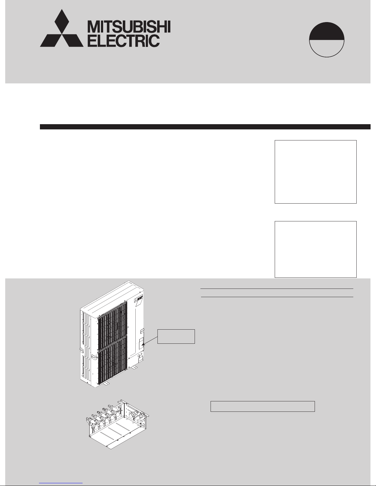
• This service manual
describes technical data of
outdoor unit and branch box.
As for indoor units, refer to
its service manual.
• RoHS compliant products
have <G> mark on the spec
name plate.
[Model Name]
<Outdoor unit>
MXZ-4C36NAHZ
MXZ-5C42NAHZ
MXZ-8C48NAHZ
MXZ-8C48NA
MXZ-8C60NA
<Branch box>
PAC-MKA50BC
PAC-MKA30BC
PAC-MKA51BC
PAC-MKA31BC
PARTS CATALOG (OCB573)
[Service Ref.]
OUTDOOR UNIT: MXZ-4C36NAHZ
BRANCH BOX: PAC-MKA51BC
Model name
indication
SPLIT-TYPE, HEAT PUMP AIR CONDITIONERS
Revision:
• Added PAC-MKA51BC,
PAC-MKA31BC,
MXZ-4C36NAHZ-U1,
MXZ-5C42NAHZ-U1,
MXZ-8C48NAHZ-U1,
MXZ-8C48NA-U1, and
MXZ-8C60NA-U1 in REVISED
EDITION-C.
• Some descriptions have been
modified.
OCH573 REVISED EDITION-B
is void.
Page 2

2
TECHNICAL CHANGES
MXZ-4C36NAHZ MXZ-4C36NAHZ-U1
MXZ-5C42NAHZ MXZ-5C42NAHZ-U1
MXZ-8C48NAHZ MXZ-8C48NAHZ-U1
MXZ-8C48NA MXZ-8C48NA-U1
Service ref. have been changed as follows.
• The shape of piping around a stop valve (T7W E04 410) has been changed.
• The shape of valve bed has been changed.
OCH573C
Page 3
3
Cautions for units utilizing refrigerant R410A
1-1. ALWAYS OBSERVE FOR SAFETY
Use new refrigerant pipes.
Charge refrigerant from liquid phase of gas
cylinder.
If the refrigerant is charged from gas phase, composition
change may occur in refrigerant and the efficiency will be
lowered.
Do not use refrigerant other than R410A.
If other refrigerant (R22, etc.) is used, chlorine in refrigerant can cause deterioration of refrigerant oil, etc.
Use a vacuum pump with a reverse flow check
valve.
Vacuum pump oil may flow back into refrigerant cycle and
that can cause deterioration of refrigerant oil, etc.
Use the following tools specifically designed for
use with R410A refrigerant.
The following tools are necessary to use R410A refrigerant.
Handle tools with care.
If dirt, dust or moisture enters into refrigerant cycle, that can
cause deterioration of refrigerant oil or malfunction of compressor.
Do not use a charging cylinder.
If a charging cylinder is used, the composition of refrigerant will change and the efficiency will be lowered.
Flare tool
Electronic refrigerant
charging scale
Vacuum pump adaptor
Size adjustment gauge
Gauge manifold
Torque wrench
Gas leak detector
Charge hose
Tools for R410A
Contamination inside refrigerant piping can cause deterioration of refrigerant oil, etc.
If large amount of mineral oil enters, that can cause deterioration of refrigerant oil, etc.
Make sure that the inside and outside of refrigerant piping is clean and it has no contaminants
such as sulfur, oxides, dirt, shaving particles, etc,
which are hazard to refrigerant cycle.
In addition, use pipes with specified thickness.
The refrigerant oil applied to flare and flange
connections must be ester oil, ether oil or
alkylbenzene oil in a small amount.
Ventilate the room if refrigerant leaks during
operation. If refrigerant comes into contact with
a flame, poisonous gases will be released.
Never use any refrigerant other than that specified.
Doing so may cause a burst, an explosion, or fire when the
unit is being used, serviced, or disposed of.
Correct refrigerant is specified in the manuals and on the
spec labels provided with our products.
We will not be held responsible for mechanical failure,
system malfunction, unit breakdown or accidents caused
by failure to follow the instructions.
Use the specified refrigerant only.
Store the piping indoors, and both ends of the
piping sealed until just before brazing.
(Leave elbow joints, etc. in their packaging.)
If dirt, dust or moisture enters into refrigerant cycle, that can
cause deterioration of refrigerant oil or malfunction of compressor.
1-2. CAUTIONS RELATED TO NEW REFRIGERANT
Before obtaining access to terminal, all supply
circuit must be disconnected.
1 SAFETY PRECAUTION
OCH573C
Page 4
4
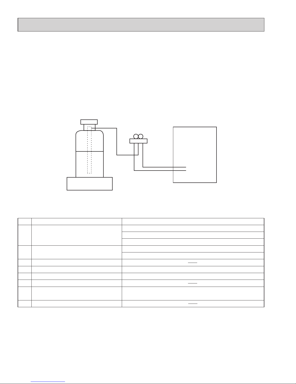
Unit
Electronic weighing scale
[3] Service tools
(1) Use the below service tools as exclusive tools for R410A refrigerant.
No. Tool name Specifications
1 Gauge manifold ·Only for R410A
·Use the existing fitting
specifications
. (UNF1/2)
·
Use high-tension side pressure of 768.7 PSIG [5.3 MPaG] or over.
2 Charge hose ·Only for R410A
·Use pressure performance of 738.2 PSIG [5.09MPaG] or over.
3 Electronic scale
4 Gas leak detector ·Use the detector for R134a, R407C or R410A.
5 Adaptor for reverse flow check ·Attach on vacuum pump.
6 Refrigerant charge base
7 Refrigerant cylinder ·Only for R410A ·Top of cylinder (Pink)
·Cylinder with syphon
8 Refrigerant recovery equipment
[2] Additional refrigerant charge
When charging directly from cylinder
(1) Check that cylinder for R410A on the market is a syphon type.
(2) Charging should be performed with the cylinder of syphon stood vertically. (Refrigerant is charged from liquid phase.)
[1] Cautions for service
(1) Perform service after recovering the refrigerant left in unit completely.
(2) Do not release refrigerant in the air.
(3) After completing service, charge the cycle with specified amount of refrigerant.
(4) If moisture or foreign matter might have entered the refrigerant piping during service, ensure to remove them.
OCH573C
Page 5
5
1-3. Cautions for refrigerant piping work
New refrigerant R410A is adopted for replacement inverter series. Although the refrigerant piping work for R410A is
same as for R22, exclusive tools are necessary so as not to mix with different kind of refrigerant. Furthermore as the
working pressure of R410A is 1.6 times higher than that of R22, their sizes of flared sections and flare nuts are different.
1 Thickness of pipes
Because the working pressure of R410A is higher compared to R22, be sure to use refrigerant piping with thickness
shown below. (Never use pipes of 7/256 in [0.7 mm] or below.)
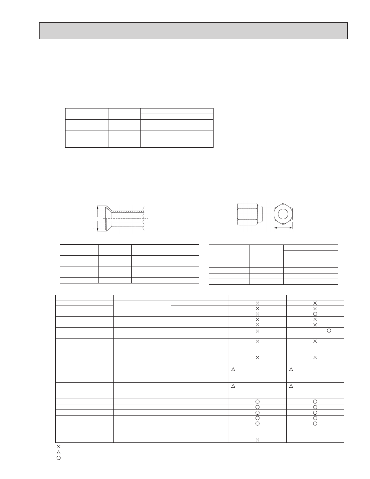
2 Dimensions of flare cutting and flare nut
The component molecules in HFC refrigerant are smaller compared to conventional refrigerants. In addition to that,
R410A is a refrigerant, which has higher risk of leakage because its working pressure is higher than that of other
refrigerants. Therefore, to enhance airtightness and strength, flare cutting dimension of copper pipe for R410A has
been specified separately from the dimensions for other refrigerants as shown below. The dimension B of flare nut for
R410A also has partly been changed to increase strength as shown below. Set copper pipe correctly referring to copper pipe flaring dimensions for R410A below. For 1/2 and 5/8 inch pipes, the dimension B changes.
Use torque wrench corresponding to each dimension.
3 Tools for R410A (The following table shows whether conventional tools can be used or not.)
1/4
3/8
1/2
5/8
3/4
6.35
9.52
12.70
15.88
19.05
1/32 [0.8]
1/32 [0.8]
1/32 [0.8]
5/128 [1.0]
—
1/32 [0.8]
1/32 [0.8]
1/32 [0.8]
5/128 [1.0]
5/128 [1.0]
Nominal
dimensions
(in)
Diagram below: Piping diameter and thickness
Outside
diameter
(mm)
Thickness
: in [mm]
R410A R22
1/4
3/8
1/2
5/8
3/4
6.35
9.52
12.70
15.88
19.05
11/32-23/64 [ 9.1]
1/2-33/64 [13.2]
41/64-21/32 [16.6]
49/64-25/32 [19.7]
—
9.0
13.0
16.2
19.4
23.3
Nominal
dimensions (in)
Flare cutting dimensions
Outside
diameter (mm)
Dimension A
( )
+0
-0.4
Unit : in [mm]
R410A R22
1/4
3/8
1/2
5/8
3/4
6.35
9.52
12.70
15.88
19.05
43/64 [17.0]
7/8 [22.0]
1-3/64 [26.0]
1-9/64 [29.0]
17.0
22.0
24.0
27.0
36.0
Nominal
dimensions (in)
Flare nut dimensions
Outside
diameter (mm)
Dimension B
Unit: in [mm]
R410A R22
—
Gauge manifold
Charge hose
Gas leak detector
Refrigerant recovery equipment
Refrigerant cylinder
Applied oil
Safety charger
Charge valve
Vacuum pump
Flare tool
Bender
Pipe cutter
Welder and nitrogen gas cylinder
Refrigerant charging scale
Vacuum gauge or thermistor vacuum gauge and
vacuum valve
Charging cylinder
Air purge, refrigerant charge
and operation check
Gas leak check
Refrigerant recovery
Refrigerant charge
Apply to flared section
Prevent compressor malfunction
when charging refrigerant by
spraying liquid refrigerant
Prevent gas from blowing out
when detaching charge hose
Vacuum drying and air
purge
Flaring work of piping
Bend the pipes
Cut the pipes
Weld the pipes
Refrigerant charge
Check the degree of vacuum. (Vacuum
valve prevents back flow of oil and refrigerant to thermistor vacuum gauge)
Refrigerant charge
Tool exclusive for R410A
Tool exclusive for R410A
Tool for HFC refrigerant
Tool exclusive for R410A
Tool exclusive for R410A
Ester oil, ether oil and
alkylbenzene oil (minimum amount)
Tool exclusive for R410A
Tool exclusive for R410A
Tools for other refrigerants can
be used if equipped with adopter for reverse flow check
Tools for other refrigerants
can be used by adjusting
flaring dimension
Tools for other refrigerants can be used
Tools for other refrigerants can be used
Tools for other refrigerants can be used
Tools for other refrigerants can be used
Tools for other refrigerants
can be used
Tool exclusive for R410A
Tools and materials Use R410A tools Can R22 tools be used?
(Usable if equipped
with adopter for rever se flow)
(Usable by adjusting
flaring dimension)
Can R407C tools be used?
Ester oil, ether oil:
Alkylbenzene oil: minimum amount
(Usable if equipped
with adopter for rever se flow)
(Usable by adjusting
flaring dimension)
: Prepare a new tool. (Use the new tool as the tool exclusive for R410A.)
: Tools for other refrigerants can be used under certain conditions.
: Tools for other refrigerants can be used.
Dimension A
Dimension B
OCH573C
Page 6

6
2 OVERVIEW OF UNITS
2-1. CONSTRUCTION OF SYSTEM
Outdoor unit
MXZ-4C36NAHZ(-U1) MXZ-5C42NAHZ(-U1)
MXZ-8C48NAHZ(-U1)
MXZ-8C48NA(-U1)
MXZ-8C60NA-U1
4HP 4.5HP 5HP 7HP
Rated capacity
(kBTU/h)
Cooling 36 42 48 60
Heating 45 48 54 66
Refrigerant R410A
Connectable
indoor unit
Capacity Type 06 to Type 36
Caution: The indoor unit which rated capacity exceeds
36 kBTU/ h (Type 36) can NOT be connected.
Number of units 2(*
1
) to 4 units 2(*1) to 5 units 2(*1) to 8 units 2(*1) to 8 units
Total system wide capacity 33 to 130% of outdoor
unit capacity
(12 to 46.8 kBTU/h)
29 to 130% of outdoor
unit capacity
(12 to 54.6 kBTU/h)
25 to 130% of outdoor
unit capacity
(12 to 62.4 kBTU/h)
20 to 130% of outdoor
unit capacity
(12 to 78 kBTU/h)
Connectable
branch box
Number of units
1 or 2 units
Connectable indoor unit lineups (Heat pump inverter type)
Model type Model name Capacity class [kBTU/h]
06 09 12 15 18 24 30 36
Wall
mounted
Deluxe
MSZ-FE09/12/18NA
MSZ-FH06/09/12/15NA, 18NA2
Designer
MSZ-EF09/12/15/18NA(W/B/S)
Standard
MSZ-GE06/09/12/15/18/24NA
MSZ-GL06/09/12/15/18/24NA
Ceiling
concealed
Low static pressure*
3
SEZ-KD09/12/15/18NA
Middle static pressure*
3
PEAD-A24/30/36AA5
4-way ceiling
cassette
2 by 2 type
SLZ-KA09/12/15NA
Standard
PLA-A12/18/24/30/36BA6
PLA-A12/18/24/30/36EA7*
4
Floor standing
MFZ-KA09/12/18NA
MFZ-KJ09/12/15/18NA
Multi-position*
2
MVZ-A12/18/24/30/36AA4
● Models other than MXZ-8C60NA
Number of connecting
multi-position unit
Constraints
2
Any indoor units other than multi-position models
are not connectable.
1
None
(Only the ordinal constraints apply.)
Option Optional accessories for indoor units and outdoor units are available.
2- branch pipe (joint): Optional parts
In case of using 1- branch box No need
In case of using 2- branch boxes
Model name Connection method
MSDD-50AR-E are
MSDD-50BR-E brazing
Branch box PAC-MKA50BC PAC-MKA51BC PAC-MKA30BC PAC-MKA31BC
Number of branches
(Indoor unit that can be connected)
5 branches
(MAX. 5 units)
3 branches
(MAX. 3 units)
Note: A maximum of 2 branch boxes can be connected to 1 outdoor unit.
● MXZ-8C60NA
(For each connected branch box)
Number of connecting
multi-position unit
Constraints
2
Any indoor units other than multi-position
models are not connectable.
1
·
The total system wide capacity should be 100%
or below including the MVZ-series unit.
· Only 1 SEZ or 1 PEAD can be included in the
connection.
*3 For MXZ-8C60NA; When connecting the SEZ and PEAD-series units, the total system wide capacity per 1 branch box should be 100% or
below including the SEZ and PEAD-series units. (Only if connecting to PAC-MKA50/51BC)
*4 When the system includes even 1 unit of PLA-A·EA7, the number of the maximum connectable indoor units is decreased as follows:
3 for MXZ-4C36NAHZ-U1, 4 for MXZ-5C42NAHZ-U1, and 6 for MXZ-8C48NA(HZ)-U1 and MXZ-8C60NA-U1
*
1
1 for MVZ model.
Single unit connection is possible with MVZ-series unit.
*2 When connecting a multi-position unit(s), set additional constraints as follows. For connections other than those specied below, consult your dealer.
Select a model according to the
connection method.
OCH573C
Page 7
7
Indoor unit (Ceiling concealed type)
Indoor unit
(Wall mounted type)
Outdoor unit
Branch box
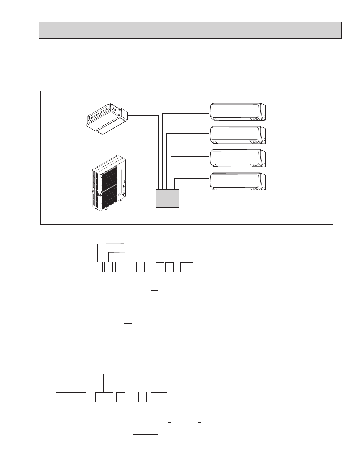
2-2. SYSTEM OUTLINE
The additional connection of the branch box together with employment of the compact trunk-looking outdoor unit can successfully realize a long distance piping for large houses. Equipped with a microcomputer, the branch box can translate the
transmission signal of indoor units to achieve the optimum control.
2-2-1. System example
2-2-2. Method for identifying
■ Outdoor unit
Development No. : A, B, ···,etc.
Power supply
N: Single phase 208/230 V 60Hz
Multi type heat pump
inverter outdoor unit
Indicates equivalent to rated cooling capacity.
(kBTU/h)
Number of connectable indoor units (MAX.)
Control and refrigerant
A : New A control and R410A
Model type
M X Z
-
4 88 C N A
P A
C
-
MK
A
5 1 B C
H Z
-
U1
Sub-number
(Indispensable)
Optional parts
Model type
Branch box (Controller)
Number of branches
5 : 5 branches
3 : 3 branches
Marketable area
A: America, Canada
■ Branch box
OCH573C
Page 8
8
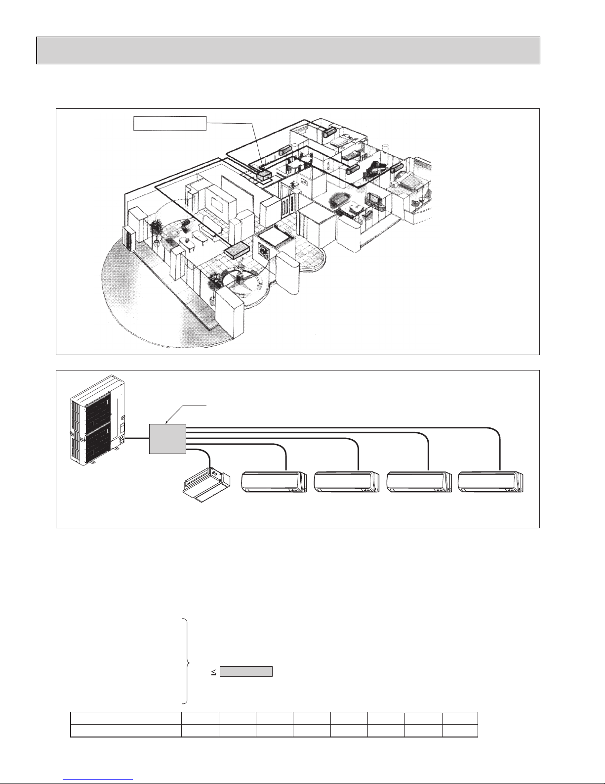
2-3. TYPICAL COMBINATION EXAMPLE
Branch box is located INSIDE of condominium
Branch box
(Inside)
Installing branch box indoors
Only 1 piping is required between the outdoor and
indoor offering a fine external view.
Branch box (5-branches type)
Outdoor unit
SEZ-18 MSZ-12 MSZ-12 MSZ-09 MSZ-09
Living
Dining Bedroom (1) Bedroom (2)
Master
bedroom
Indoor unit type (capacity class)
Rated capacity (cooling) (kBTU/h)066
09
9
12
12
15
15
24
24
18
18
30
30
36
36
■ System example of 5 indoor units
■ Verification (In case of MXZ-8C48NAHZ)
The rated capacity should be determined by observing the table below. The unit’s quantities are limited to 1(*) to 8
units. For the next step, make sure that the selected total rated capacity is in a range of 12 to 62.4 kBTU/h.
The total indoor unit capacity should be within the outdoor units. (= 48.0 kBTU/h is preferred).
Combination of excessive indoor units and an outdoor unit may reduce the capacity of each indoor unit.
The rated indoor capacity is as the table below.
*Single unit connection is possible only with MVZ model. Connect 2 or more units for models other than MVZ.
Example:
Total rated capacity
60 62.4 kBTU/h
MSZ-09 = 9
+
+
+
+
SEZ-18 = 18
MSZ-12 = 12
MSZ-12 = 12
MSZ-09 = 9
OCH573C
Page 9
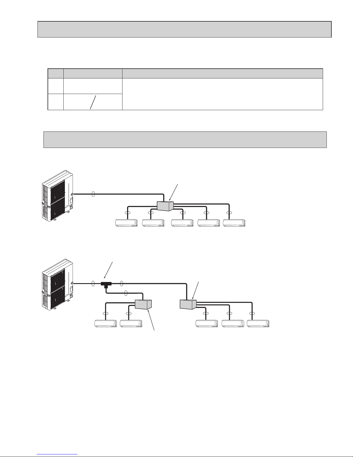
2-4. SIMPLIFIED PIPING SYSTEM
Piping connection size
Liquid
Gas
{3/8 inch
[9.52 mm]
{5/8 inch
[15.88 mm]
The piping connection size differs according to the type and capacity of indoor units.
Match the piping connection size of branch box with indoor unit.
If the piping connection size of branch box does not match the piping connection size of
indoor unit, use optional different-diameter (deformed) joints to the branch box side.
(Connect deformed joint directly to the branch box side.)
A B
{3/4 inch*
[19.05 mm]
* MXZ-8C60NA only
Flare connection employed. (No brazing!)
A
B B B B B
Branch box
■ In case of using 1-branch box
Flare connection employed (No brazing)
A
A
A
B B
B B B
2 branches pipe (joint)
: optional parts
Branch box #1
Branch box #2
■ In case of using 2-branch boxes
■ Installation procedure (2 branches pipe (joint))
Refer to the installation manuals of MSDD-50AR-E and MSDD-50BR-E.
9
OCH573C
Page 10
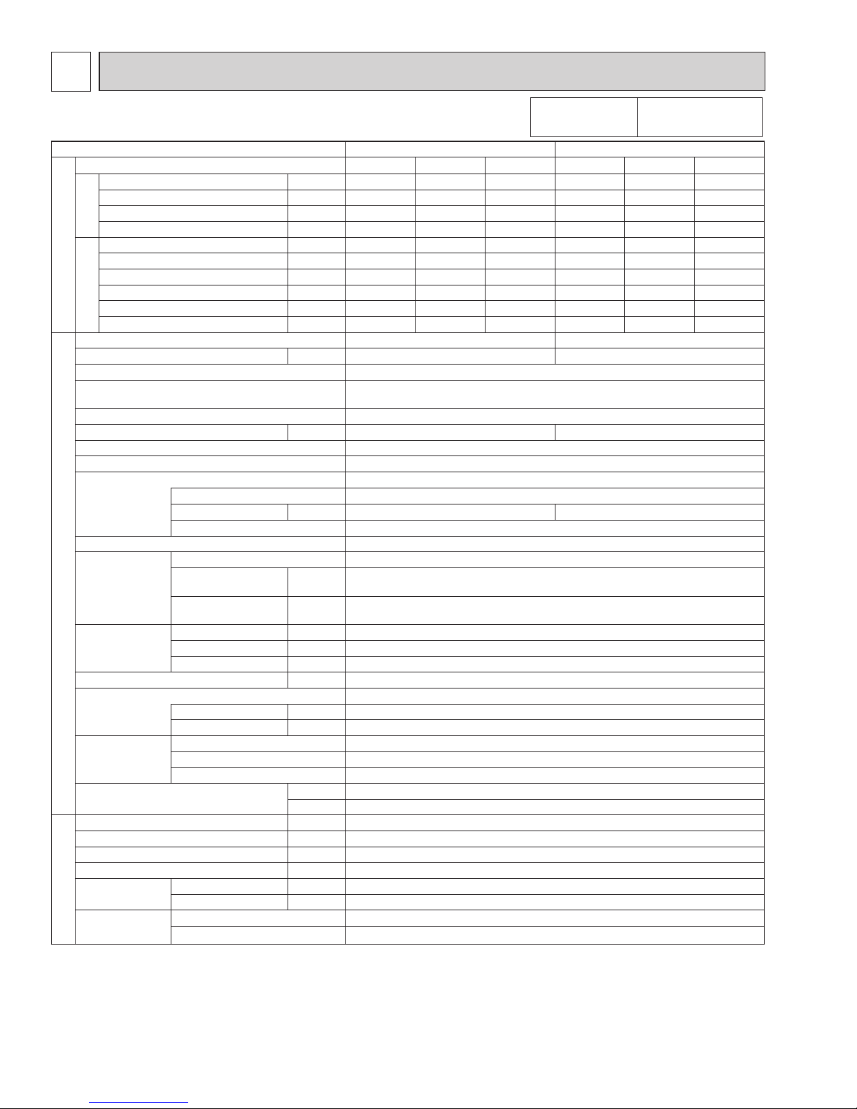
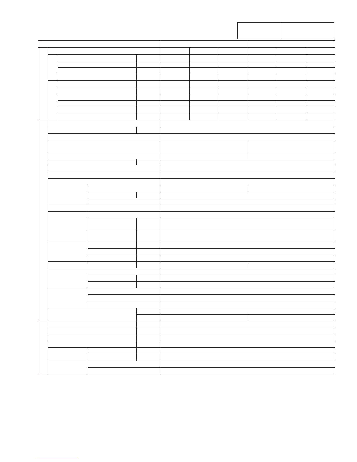
3 SPECIFICATIONS
3-1.
OUTDOOR UNIT
:
MXZ-4C36/5C42/8C48NAHZ(-U1), MXZ-8C48NA(-U1), MXZ-8C60NA-U1
Conversion formula:
kcal/h = kW o 860
BTU/h = kW o 3412
CFM = m
3
/min o 35.31
10
Service Ref. MXZ-4C36NAHZ(-U1) MXZ-5C42NAHZ(-U1)
Standard performance
Indoor type
Non-Ducted
Mix Ducted
Non-Ducted
Mix Ducted
Cooling
Capacity Rated*
1
BTU/h 36,000 36,000 36,000 42,000 42,000 42,000
Rated power consumption*
1
W 2,570 2,845 3,180 3,130 3,470 3,890
EER BTU/Wh 14.00 12.65 11.30 13.40 12.10 10.80
SEER BTU/Wh 19.1 17.5 15.8 19.0 17.0 15.0
Heating
Capacity Rated 47°F
*
1
BTU/h 45,000 45,000 45,000 48,000 48,000 48,000
Capacity Max. 17°F
*
2
BTU/h 45,000 45,000 45,000 48,000 48,000 48,000
Capacity Max. 5°F BTU/h 45,000 45,000 45,000 48,000 48,000 48,000
Rated power consumption 47°F
*
1
W 3,340 3,795 4,250 3,430 3,890 4,350
COP 47°F
*1 BTU/Wh 3.95 3.48 3.10 4.10 3.62 3.23
HSPF 4/
5
BTU/Wh 11.3/9.2 10.7/8.9 10.1/8.5 11.0/9.1 10.6/9.0 10.1/8.8
OUTDOOR UNIT
Connectable indoor units (Max.) 4 5
Max. Connectable Capacity BTU/h 46,000 54,000
Power supply 1 Phase 208/230 V, 60 Hz
Breaker Size/Max. fuse size 50 A/52 A
50 A/50 A (for the models with U1)
Min. circuit ampacity 42 A
Sound level (Cool/Heat) dB 49/ 53 50/ 54
External nish Munsell 3Y 7.8/ 1.1
Refrigerant control Linear Expansion Valve
Compressor Hermetic
Model ANB33FJSMT
Motor output kW 2.8 3.0
Starting method Inverter
Heat exchanger Plate n coil
Fan Fan (drive) × No. Propeller fan × 2
Fan motor output kW 0.06 + 0.06
0.074 + 0.074 (for the models with U1)
Airow m³/min
(CFM)
110 (3885)
Dimensions
(H × W × D)
W
in (mm)
41-11/32 (1050)
D
in (mm)
13+1 (330+25)
H
in (mm)
52-11/16 (1338)
Weight lb (kg) 276 (125)
Refrigerant R410A
Charge lb (kg) 10 lbs. 9 oz.(4.8)
Oil/Model oz (L) 73 (2.3)/Ethereal oil (FV50S)
Protection devices
High pressure protection HP switch
Compressor protection
Compressor thermo, Overcurrent detection
Fan motor protection Overheating/Voltage protection
Guaranteed operation range (cool) D.B 23 to 115°F [ D.B.−5 to 46°C ]
*
3
(heat) D.B. −13 to 70°F [D.B. −25 to 21°C ]
REFRIGERANT PIPING
Total Piping length (Max.) ft (m) 492 (150)
Farthest ft (m) 262 (80)
Max. Height difference ft (m) 164 (50)
*
4
Chargeless length ft (m) 0
Piping diameter Liquid
[inch (mm)
[3/8 (9.52)
Gas
[inch (mm)
[5/8 (15.88)
Connection
method
Indoor side Flared
Outdoor side Flared
*1
Rating conditions Cooling Indoor : D.B. 80°F/W.B. 67 °F [D.B.26.7°C/W.B. 19.4°C]
Outdoor : D.B. 95°F [D.B. 35.0°C]
Heating Indoor : D.B. 70°F [D.B. 21.1°C]
Outdoor : D.B. 47°F/W.B. 43°F [D.B. 8.3°C/W.B. 6.1°C]
*
2
Conditions Heating Indoor : D.B. 70°F [D.B. 21.1°C]
Outdoor : D.B. 17°F/W.B. 15°F [D.B. −8.3°C/W.B. −9.4°C]
*
3
D.B. 5 to 115°F [D.B. −15 to 46°C], when an optional Air Outlet Guide is installed.
*
4
131 ft [40 m], in case of installing outdoor unit lower than indoor unit.
Note: Refer to the indoor unit's service manual for the indoor units specications.
OCH573C
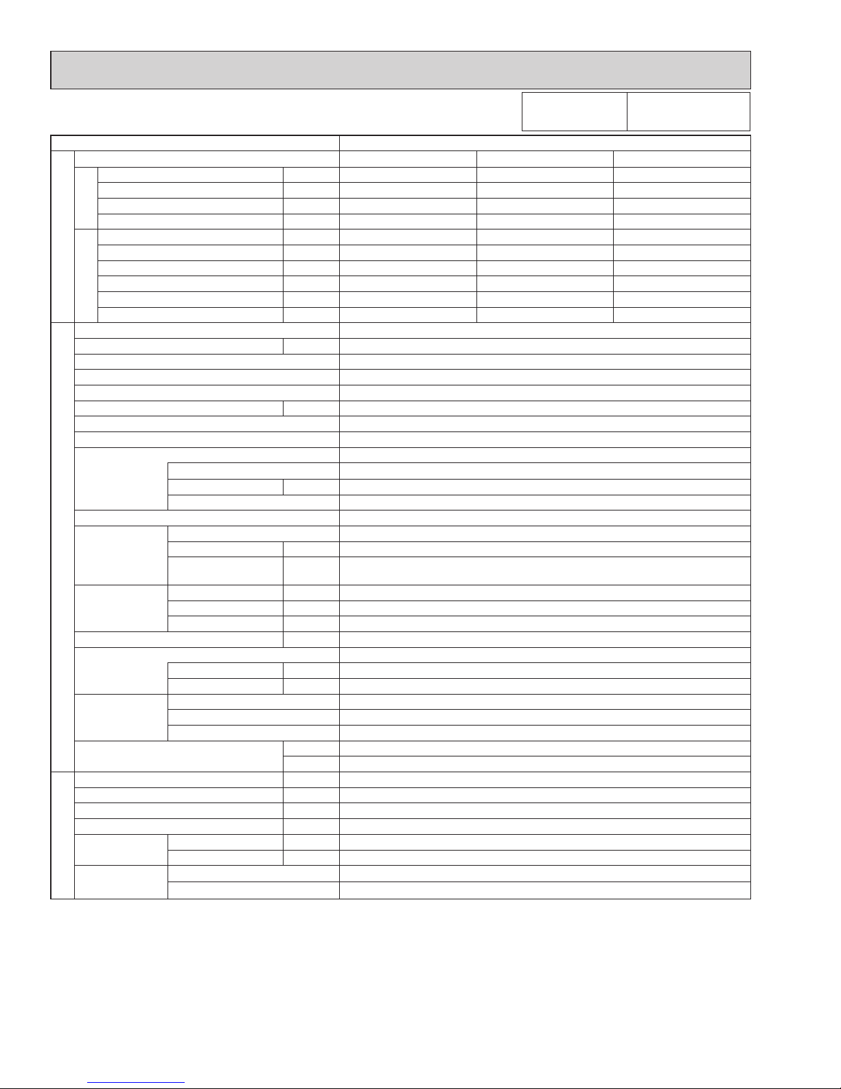
Page 11
11
Service Ref. MXZ-8C48NAHZ(-U1) MXZ-8C48NA(-U1)
Standard performance
Indoor type
Non-Ducted
Mix Ducted
Non-Ducted
Mix Ducted
Cooling
Capacity Rated*
1
BTU/h 48,000 48,000 48,000 48,000 48,000 48,000
Rated power consumption*1
W 4,000 4,465 5,050 4,000 4,465 5,050
EER BTU/Wh 12.00 10.75 9.50 12.00 10.75 9.50
SEER BTU/Wh 18.9 16.8 14.7 18.9 16.8 14.7
Heating
Capacity Rated 47°F
*
1
BTU/h 54,000 54,000 54,000 54,000 54,000 54,000
Capacity 17°F
*
2
BTU/h 54,000 54,000 54,000 36,600 36,600 36,600
Capacity 5°F BTU/h 54,000 54,000 54,000 32,400 32,400 32,400
Rated power consumption 47°F*1
W 4,220 4,605 4,990 4,220 4,605 4,990
COP 47°F
*
1
BTU/Wh 3.75 3.44 3.17 3.75 3.44 3.17
HSPF 4/
5
BTU/Wh 11.0/9.2 10.5/9.2 10.0/9.2 11.4/8.7 10.8/8.6 10.1/8.4
OUTDOOR UNIT
Connectable indoor units (Max.) 8
Max. Connectable Capacity BTU/h 62,000
Power supply 1 Phase 208/230 V, 60 Hz
Breaker Size / Max. fuse size 50 A/ 52 A
50 A/50 A (for the models with U1)
40 A/52 A
40 A/50 A (for the models with U1)
Min. circuit ampacity 42 A 37 A
Sound level (Cool/Heat) dB 51/ 54
External nish Munsell 3Y 7.8 / 1.1
Refrigerant control Linear Expansion Valve
Compressor Hermetic
Model ANB33FJSMT ANB33FNHMT
Motor output kW 3.4
Starting method Inverter
Heat exchanger Plate n coil
Fan Fan (drive) × No. Propeller fan × 2
Fan motor output kW 0.06 + 0.06
0.074 + 0.074 (for the models with U1)
Airow m³/min
(CFM)
110 (3885)
Dimensions
(H × W × D)
W inch (mm) 41-11/32 (1050)
D inch (mm) 13+1 (330+25)
H inch (mm) 52-11/16 (1338)
Weight lb (kg) 276 (125) 269 (122)
Refrigerant R410A
Charge lb (kg) 10 lbs. 9 oz. (4.8 )
Oil / Model oz (L) 73 (2.3) / Ethereal oil (FV50S)
Protection
devices
High pressure protection HP switch
Compressor protection
Compressor thermo, Over current detection
Fan motor protection Overheating/Voltage protection
Guaranteed operation range (cool) D.B. 23 to 115°F [ D.B. −5 to 46°C]
*3
(heat) D.B. −13 to 70°F [D.B. −25 to 21°C] D.B. −4 to 70°F [D.B. −20 to 21°C]
REFRIGERANT PIPING
Total Piping length (Max.) ft (m) 492 (150)
Farthest ft (m) 262 (80)
Max. Height difference ft (m) 164 (50)
*4
Chargeless length ft (m) 0
Piping diameter Liquid
[inch (mm)
[3/8 (9.52)
Gas
[inch (mm)
[ 5/8 (15.88)
Connection
method
Indoor side Flared
Outdoor side Flared
*
1
Rating conditions Cooling Indoor : D.B. 80°F/W.B. 67°F [D.B. 26.7°C/W.B. 19.4°C]
Outdoor : D.B. 95°F [D.B. 35.0°C]
Heating Indoor : D.B. 70°F [D.B. 21.1°C]
Outdoor : D.B. 47°F/W.B. 43°F [D.B. 8.3°C/W.B. 6.1°C]
*
2
Conditions Heating Indoor : D.B. 70°F [D.B. 21.1°C]
Outdoor : D.B. 17°F/W.B. 15°F [D.B. −8.3°C/W.B. −9.4°C]
*
3
D.B. 5 to 115°F [D.B. −15 to 46°C], when an optional Air Outlet Guide is installed.
*
4
131 ft [40 m], in case of installing outdoor unit lower than indoor unit.
Note: Refer to the indoor unit's service manual for the indoor units specications.
Conversion formula:
kcal/h = kW o 860
BTU/h = kW o 3412
CFM = m
3
/min o 35.31
OCH573C
Page 12
12
Service Ref. MXZ-8C60NA-U1
Standard performance
Indoor type
Non-Ducted
Mix Ducted
Cooling
Capacity Rated*
1
BTU/h 60,000 60,000 60,000
Rated power consumption*
1
W 4,800 5,525 6,250
EER BTU/Wh 12.50 11.05 9.60
SEER BTU/Wh 17.4 16.3 15.1
Heating
Capacity Rated 47°F
*
1
BTU/h 66,000 66,000 66,000
Capacity Max. 17°F
*
2
BTU/h 65,000 61,500 58,000
Capacity Max. 5°F BTU/h 57,000 49,500 42,000
Rated power consumption 47°F
*
1
W 4,870 4,810 4,750
COP 47°F
*1 BTU/Wh 3.40 3.40 3.40
HSPF 4/
5
BTU/Wh 10.50/8.50 10.25/8.25 10.00/8.00
OUTDOOR UNIT
Connectable indoor units (Max.) 8
Max. Connectable Capacity BTU/h 78,000
Power supply 1 Phase 208/230 V, 60 Hz
Breaker Size/Max. fuse size 50 A/52 A
Min. circuit ampacity 46A
Sound level (Cool/Heat) dB 58/59
External nish Munsell 3Y 7.8/ 1.1
Refrigerant control Linear Expansion Valve
Compressor Hermetic
Model ANB66FFZMT
Motor output kW 4.2
Starting method Inverter
Heat exchanger Plate n coil
Fan Fan (drive) × No. Propeller fan × 2
Fan motor output kW 0.2 + 0.2
Airow m³/min
(CFM)
138 (4879)
Dimensions
(H × W × D)
W
in (mm)
41-11/32 (1050)
D
in (mm)
13+1 (330+25)
H
in (mm)
52-11/16 (1338)
Weight lb (kg) 309 (140)
Refrigerant R410A
Charge lb (kg) 11 lbs. 4 oz.(5.1)
Oil/Model oz (L) 73 (2.3)/Ethereal oil (FV50S)
Protection devices
High pressure protection HP switch
Compressor protection
Compressor thermo, Overcurrent detection
Fan motor protection Overheating/Voltage protection
Guaranteed operation range (cool) D.B 23 to 115°F [ D.B.−5 to 46°C ]
*
3
(heat) D.B. −4 to 70°F [D.B. −20 to 21°C ]
REFRIGERANT PIPING
Total Piping length (Max.) ft (m) 492 (150)
Farthest ft (m) 262 (80)
Max. Height difference ft (m) 164 (50)
*
4
Chargeless length ft (m) 0
Piping diameter Liquid
[inch (mm)
[3/8 (9.52)
Gas
[inch (mm)
[3/4 (19.05)
Connection
method
Indoor side Flared
Outdoor side Flared
*1
Rating conditions Cooling Indoor : D.B. 80°F/W.B. 67 °F [D.B.26.7°C/W.B. 19.4°C]
Outdoor : D.B. 95°F [D.B. 35.0°C]
Heating Indoor : D.B. 70°F [D.B. 21.1°C]
Outdoor : D.B. 47°F/W.B. 43°F [D.B. 8.3°C/W.B. 6.1°C]
*
2
Conditions Heating Indoor : D.B. 70°F [D.B. 21.1°C]
Outdoor : D.B. 17°F/W.B. 15°F [D.B. −8.3°C/W.B. −9.4°C]
*
3
D.B. 5 to 115°F [D.B. −15 to 46°C], when an optional Air Outlet Guide is installed.
*
4
131 ft [40 m], in case of installing outdoor unit lower than indoor unit.
Note: Refer to the indoor unit's service manual for the indoor units specications.
Conversion formula:
kcal/h = kW o 860
BTU/h = kW o 3412
CFM = m
3
/min o 35.31
OCH573C
Page 13
13
kW
A
inch (mm)
inch (mm)
inch (mm)
lb (kg)
inch (mm)
inch (mm)
inch (mm)
inch (mm)
Connectable number of indoor units
Power supply
Input
Running current
External finish
Dimensions
Weight
Piping
connection
(Flare)
Width
Depth
Height
Branch (indoor side)
Main (outdoor side)
Liquid
Gas
Liquid
Gas
Maximum 3
15 (6.7 )
[1/4 (6.35)
× 3 {A,B,C}
[3/8 (9.52) × 3 {A,B,C}
Maximum 5
16 (7.4)
[1/4 (6.35) × 5 {A,B,C,D,E}
[ 3/8 (9.52) × 4 {A,B,C,D},
[ 1/2 (12.7) × 1{E}
PAC-MKA50BC
PAC-MKA51BC
PAC-MKA30BC
PAC-MKA31BC
Single phase, 208/230 V, 60 Hz
0.003
0.05
Galvanized sheets
17-23/32 (450)
11-1/32 (280)
6-11/16 (170)
[3/8 (9.52)
[ 5/8 (15.88)
*
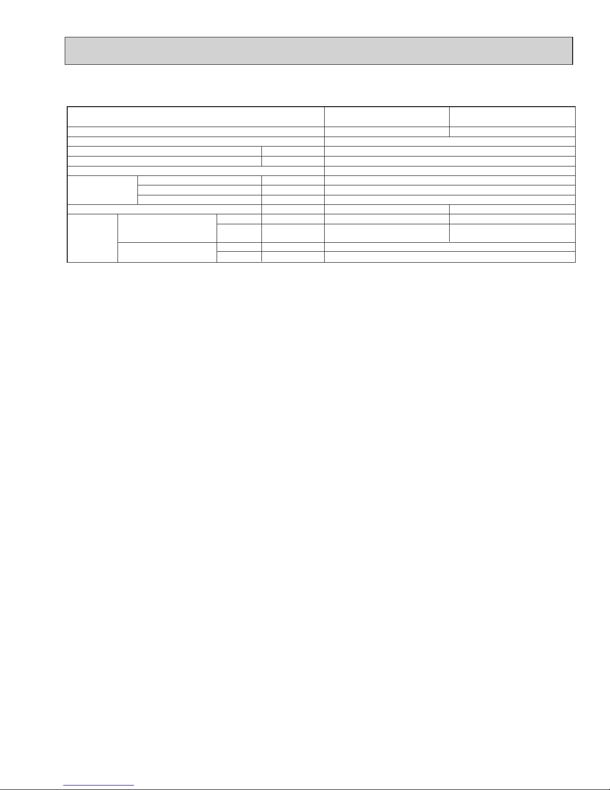
Model name
3-2. BRANCH BOX: PAC-MKA50BC PAC-MKA51BC PAC-MKA30BC PAC-MKA31BC
*The piping connection size differs according to the type and capacity of indoor units. Match the piping connection size for indoor
and branch box. If the piping connection size of branch box does not match the piping connection size of indoor units, use
optional different-diameter (deformed) joints to the branch box side. (Connect deformed joint directly to the branch box side.)
OCH573C
Page 14
14
4
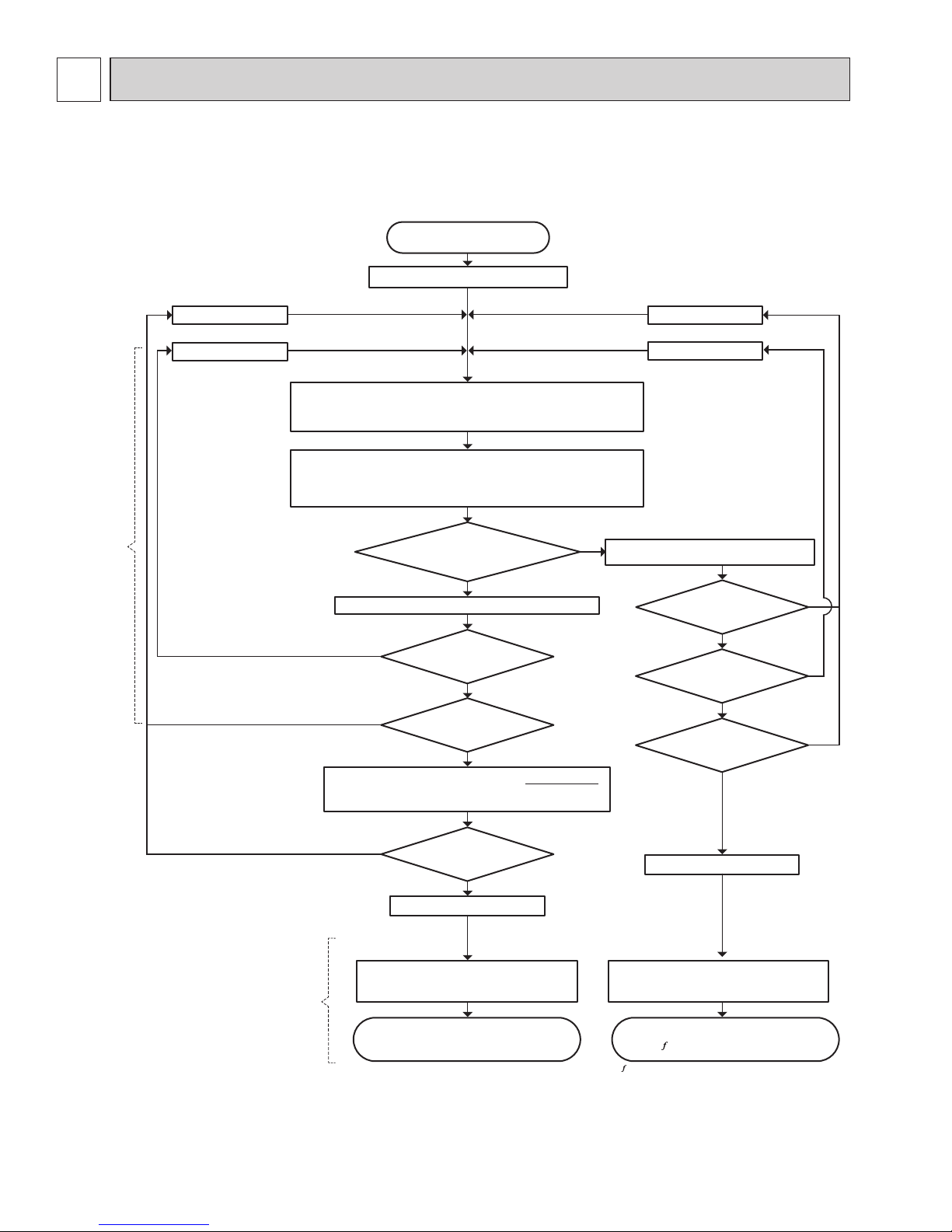
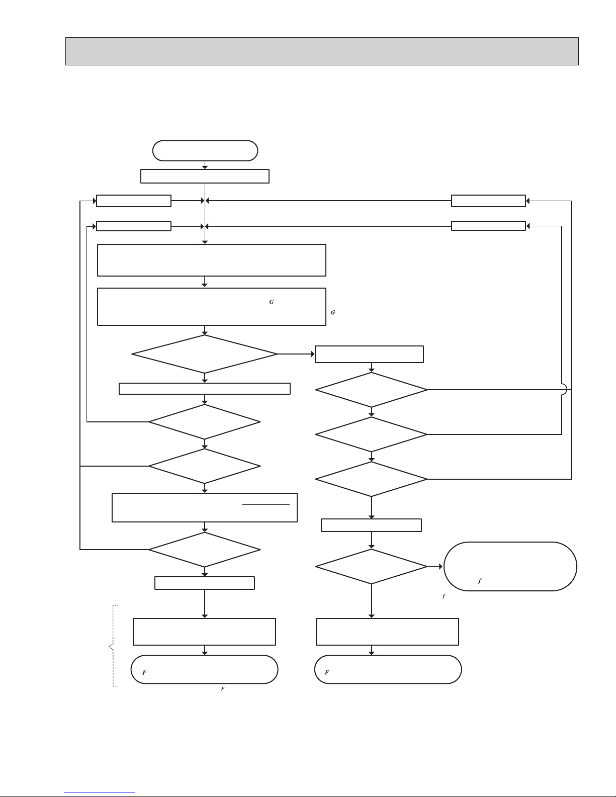
4-1. SELECTION OF COOLING/HEATING UNITS
DATA
How to determine the capacity when less than or equal 100% indoor model size units are connected in total:
The purpose of this flow chart is to select the indoor and outdoor units. For other purposes, this flow chart is intended only for reference.
No
Yes
Temporarily select the Indoor/Outdoor Units
Reselect the outdoor units
Reselect the indoor units
Reselect the outdoor units
Reselect the indoor units
Indoor Unit
n
Total Indoor Units Capacity (CTi) = ∑ (Individual Rated Indoor Unit Capacity CTik ×
k=1
Individual Indoor Temperature Correction Coef.
α
k
) (Figure 1, 4)
Outdoor Unit
*1
Outdoor Unit Capacity (CTo) = Rated Outdoor Unit Capacity × Outdoor
Temperature Correction Coef. (Figure 2, 5) × Piping Length
Correction Coef. (Figure 3, 6) × Defrost Correction Coef. (in heating operation, Table 1)
Maximum Capacity(CT
max
) = CT
o
Yes
Completed Selecting Units
Want to change to smaller
indoor units?
Does it fulfill the load of
each room?
CT
o
≤ CT
i
L ≤ CT
o
Maximum Capacity(CT
max
) = CT
i
L ≤ CT
i
Need to select smaller
outdoor unit?
Does it fulfill the load of
each room?
Outdoor Unit Input = Rated Outdoor Unit Input ×
c
ave
Determine the load (L) and
the Indoor/Outdoor Temperature
n: Total Number of Indoor Units
k: Indoor Unit Number
Yes
No
No
No
No
Yes
No
No
Yes
Yes
Capacity
Determination
Input
Calculation
Average Indoor temp. power input Coef. (
c
ave
) Average Indoor temp. power input Coef. (
c
ave
)
c
ave
= ∑ {ck × (Mk/ ∑ Mk)}
n
k=1
n
k=1
c
ave
= ∑ {ck × (Mk/ ∑ Mk)}
n
k=1
n
k=1
(If indoor to outdoor connectable
capacity ratio is less than 100%, the
capacity correction is set as 100% )
*ck:
Outdoor unit power input coefficient of k indoor unit room temp. (Refer to 4-2.)
*Mk:
Number part of the k indoor unit model (e.g. P80 → 80)
∑ (CT
im
×
α
m
)
n
m=1
Individual Indoor Unit Capacity: CT'ik= CT
max
×
CTik ×
α
k
Outdoor Unit Input = Rated Outdoor Unit Input ×
c
ave
× (CTi )
Completed Selecting Units
(x) is the approximate correction function when less than or equal
100% model size units are input as connected.
Yes
OCH573C
Page 15
15
How to determine the capacity when greater than 100% indoor model size units are connected in total:
No
Yes
Temporarily select the indoor/outdoor units
Reselect the outdoor units
Reselect the indoor units
Reselect the outdoor units
Reselect the indoor units
Indoor Unit
n
Total Indoor Units Capacity (CTi) = ∑ (Individual Rated Indoor Unit Capacity CT
ik
×
k=1
Individual Indoor Temperature Correction Coef.
α
k
) (Figure 1, 4)
Outdoor Unit
*1
Maximum Capacity(CT
max
) = CT
o
Yes
Want to change to smaller
indoor units?
Does it fulfill the load of
each room?
CT
o
≤ CT
i
L ≤ CT
o
Maximum Capacity(CT
max
) = CT
i
L ≤ CT
i
Need to select smaller
outdoor unit?
Does it fulfill the load of
each room?
Rated Outdoor Unit Capacity
< Total Indoor Units Capacity
Outdoor Unit Input
= Rated Outdoor Unit Input ×
Outdoor Temperature
Correction
Coef.
× (CT
i
)
Determine the load (L) and
the Indoor/Outdoor Temperature
n: Total Number of Indoor Units
k: Indoor Unit Number
Yes
Yes
No
No
No
No
Yes
No
No
No
Yes
Yes
Yes
Average Indoor temp. power input Coef. (
c
ave
)
= ∑ {c
k
× (Mk/ ∑ Mk)}
n
k=1
n
k=1
The purpose of this flow chart is to select the indoor and outdoor units. For other purposes, this flow chart is intended only for reference.
*ck:
Outdoor unit power input coefficient of k indoor unit room temp. (Refer to 4-2.)
*Mk:
Number part of the k indoor unit model (e.g. P80 → 80)
Average Indoor temp. power input Coef. (
c
ave
)
c
ave
= ∑ {ck × (Mk/ ∑ Mk)}
n
k=1
n
k=1
Outdoor Unit Input =Rated Outdoor Unit Input ×
c
ave
Outdoor Unit Input = Rated Outdoor Unit Input ×
c
ave
× (CTi )
∑ (CT
im
×
α
m
)
n
m=1
Individual Indoor Unit Capacity: CT'ik= CT
max
×
CTik ×
α
k
Completed Selecting Units
Completed Selecting Units
(x) is the approximate correction function when greater
than 100% model size units are connected.
Outdoor Unit Capacity (CTo) = Rated Outdoor Unit Capacity × ( )
× Outdoor Temperature Correction Coef. (Figure 2, 5)
× Piping Length Correction Coef. (Figure 3, 6) × Defrost Correction Coef. (in heating, Table 1)
(x) is the approximate correction function when greater than 100%
model size units are input as connected.
(x) is the approximate correction function when less than or equal
100% model size units are input as connected.
CT
i
× (CTi )
Input
Calculation
OCH573C
Page 16
16
<Cooling>
Design Condition
Outdoor Design Dry Bulb Temperature 98.6ºF (37.0ºC)
Total Cooling Load 29.6 kBTU/h
Room1
Indoor Design Dry Bulb Temperature 80.6ºF (27.0ºC)
Indoor Design Wet Bulb Temperature 68.0ºF (20.0ºC)
Cooling Load 13.6 kBTU/h
Room2
Indoor Design Dry Bulb Temperature 75.2ºF (24.0ºC)
Indoor Design Wet Bulb Temperature 66.2ºF (19.0ºC)
Cooling Load 16.0 kBTU/h
<Other>
Indoor/Outdoor Equivalent Piping Length 250 ft
1. Cooling Calculation
(1) Temporary Selection of Indoor Units
Room1
MSZ-FH15
15.0 kBTU/h (Rated)
Room2
MSZ-FH18
17.2 kBTU/h (Rated)
(2) Total Indoor Units Capacity
15 + 18 = 33
(3) Selection of Outdoor Unit
The P36 outdoor unit is selected as total indoor units capacity is P33
MXZ-4C36
36.0 kBTU/h
(4) Total Indoor Units Capacity Correction Calculation
Room1
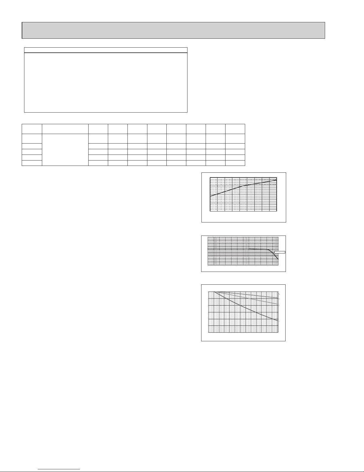
Indoor Design Wet Bulb Temperature Correction (68.0ºF)
1.02 (Refer to Figure 1)
Figure 1
Indoor unit temperature correction
To be used to correct indoor unit only
Figure 2 Outdoor unit temperature correction
To be used to correct outdoor unit only
Figure 3
Correction of refrigerant piping length
Room2
Indoor Design Wet Bulb Temperature Correction (66.2ºF)
0.95 (Refer to Figure 1)
CTi = Σ (Indoor Unit Rating × Indoor Design Temperature Correction)
= 15.0 × 1.02 + 17.2 × 0.95
= 31.6 kBTU/h
(5) Outdoor Unit Correction Calculation
Outdoor Design Dry Bulb Temperature Correction (98.6ºF)
0.98 (Refer to Figure 2)
Piping Length Correction (250 ft)
0.93 (Refer to Figure 3)
Total Outdoor Unit Capacity (CTo)
Total Indoor Units Capacity (CTi)
CTo = Outdoor Rating × Outdoor Design Temperature Correction × Piping Length Correction
= 36.0 × 0.98 × 0.93
= 32.8 kBTU/h
(6) Determination of Maximum System Capacity
Comparison of Capacity between Total Indoor Units Capacity (CTi) and Total Outdoor Unit Capacity (CTo)
CTi = 31.6 < CTo = 32.8, thus, select CTi.
CTx = CTi = 31.6 kBTU/h
(7) Comparison with Essential Load
Against the essential load 29.6 kBTU/h, the maximum system capacity is 31.6 kBTU/h: Proper outdoor units have been selected.
(8) Calculation of Maximum Indoor Unit Capacity of Each Room
CTx = CTi, thus, calculate by the calculation below
Room1
Indoor Unit Rating × Indoor Design Temperature Correction
= 15.0 × 1.02
= 15.3 kBTU/h
OK: fulfills the load 13.6 kBTU/h
Room2
Indoor Unit Rating × Indoor Design Temperature Correction
= 17.2 × 0.95
= 16.3 kBTU/h OK: fulfills the load 16.0 kBTU/h
Go on to the heating trial calculation since the selected units fulfill the cooling loads of Room 1, 2.
Indoor
Temperature
Ratio of cooling capacity
Indoor Temperature
[°F W.B.]
[°C W.B.]
-15 -10
-5 0 5 10 15 20 25 30 35 40 45
5 14
23 32 41 50 59 68 77 86 95 104 113
0.5
0.6
0.7
0.8
0.9
1.0
1.1
1.2
1.3
1.4
Ratio of cooling capacity
Outdoor Temperature
[°C D.B.]
[°F W.B.]
67.0°F(19.4°C) W.B
15 16 17 18 19 20 21 22 23 24
59 60.8 62.6 64.4 66.2 68 69.8 71.6 73.4 75.2
0.4
0.6
0.8
1.0
1.2
0 20 40 60 80 100 120 140 160 180 200 220 240 260
0.70
0.75
0.80
0.85
0.90
0.95
1.00
18 [kBTU/h]
27 [kBTU/h]
36 [kBTU/h]
Capacity ratio
Piping equivalent length (ft)
Total capacity of indoor unit
46.8 [kBTU/h]
Capacity of indoor unit
Model Number for indoor
unit
Model 06Model 09Model 12Model 15Model 18Model 24Model 30Model
36
M series Model Capacity [KBtu/h]
6.0 9.0 12.0
14.0*
1
15.0*
2
17.0*3
17.2*
4
22.5 ─ ─
P series ─ ─ 12.0 ─ 18.0 24.0 30.0 36.0
SEZ ─ 8.1 11.5 14.1 17.2 ─ ─ ─
SLZ ─ 8.4 11.1 15.0 ─ ─ ─ ─
MVZ ─ ─ 12.0 ─ 18.0 24.0 30.0 36.0
*1 For MSZ-GE/GL15NA
*
2
For the models other than
*1 above
*3 For MFZ-KA/KJ18NA
*
4
For the models other than
*3 above
OCH573C
Page 17
17
<Hea ting>
Design Condition
Outdoor Design W et Bulb Temperature 35.6ºF (2.0ºC)
Total Heating Load 34.4 kBTU/h
Room1
Indoor Design Dry Bulb Temperature 69.8ºF (21.0ºC)
Heating Load
16.3 kBTU/h
Room2
Indoor Design Dry Bulb Temperature 73.4ºF (23.0ºC)
Heating Load
18.1 kBTU/h
<Other>
Indoor/Outdoor Equivalent Piping Length 230 ft
2. Hea ting Calcula tion
(1) Temporary Selection of Indoor Units
Room1
MSZ-FH15 18.0 kBUT/h (Rated)
20.3 kBUT/h (Rated)
Room2
MSZ-FH18
(2) Total Indoor Units Capacity
15 + 18 = 33
(3) Selection of Outdoor Unit
The P36 outdoor unit is selected as total indoor units capacity is P33
MXZ-4C36 45.0 kBUT/h
(4) Total Indoor Units Capacity Correction Calculation
Room1
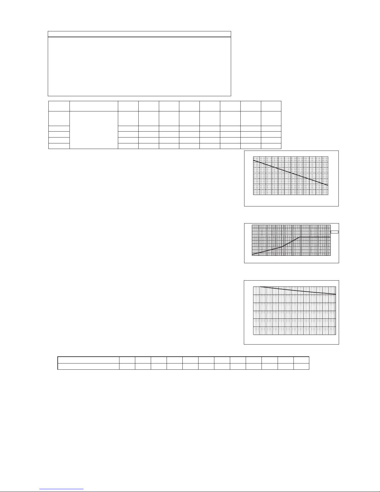
Indoor Design Dry Bulb Temperature Correction (69.8ºF)
1.00 (Refer to Figure 4)
Room2
Indoor Design Dry Bulb Temperature Correction (73.4ºF)
0.92 (Refer to Figure 4)
CTi = Σ (Indoor Unit Rating × Indoor Design Temperature Correction)
= 18.0 × 1.00 + 20.3 × 0.92
= 36.7 kBTU/h
(5) Outdoor Unit Correction Calculation
Outdoor Design Wet Bulb Temperature Correction (35.6ºF)
1.0 (Refer to Figure 5)
Piping Length Correction (230 ft)
Defrost Correction
0.96 (Refer to Figure 6)
0.89 (Refer to Table 1)
Total Outdoor Unit Capacity (CTo)
Total Indoor Units Capacity (CTi)
CTo = Outdoor Unit Rating × Outdoor Design Temperature Correction × Piping Length
Correction × Defrost Correction
= 45.0 × 1.0 × 0.96 × 0.89
= 38.4 kBTU/h
(6) Determination of Maximum System Capacity
Comparison of Capacity between Total Indoor Units Capacity (CTi) and Total Outdoor Unit Capacity (CTo)
CTi = 36.7 < CTo = 38.4, thus, select CTi.
CTx = CTi = 36.7 kBTU/h
(7) Comparison with Essential Load
Against the essential load 34.4 kBTU/h, the maximum system capacity is 36.7 kBTU/h: Proper outdoor units have been selected.
(8) Calculation of Maximum Indoor Unit Capacity of Each Room
CTx = CTi, thus, calculate by the calculation below
Room1
Maximum Capacity × Room1 Capacity after the Temperature Correction/(Room1,2 Total Capacity after the Temperature Correction
= 36.7 × (18.0 × 1.00) / (18.0 × 1.00 + 20.3 × 0.92)
= 18.0 kBTU/h OK: fulfills the load 16.3 kBTU/h
Room2
Maximum Capacity × Room1 Capacity after the Temperature Correction/(Room1,2 Total Capacity after the Temperature Correction
= 36.7 × (20.3 × 0.92) / (18.0 × 1.00 + 20.3 × 0.92)
= 18.7 kBTU/h OK: fulfills the load 18.1 kBTU/h
Completed selecting units since the selected units fulfill the heating loads of Room 1, 2.
Figure 4 Indoor unit temperature correction
To be used to correct indoor unit only
Figure 5 Outdoor unit temperature correction
To be used to correct outdoor unit only
Figure 6 Correction of refrigerant piping length
-4 5 14 23 32 41 50 59
-25
-20 -15 -10 -5 0 5 10 15
0.4
0.5
0.6
0.7
0.8
0.9
0.8
0.5
0.6
0.7
1.0
1.1
1.2
1.0
1.1
1.3
1.4
Ratio of heating capacity
Outdoor Temperature [°C W.B.]
70.0°F (21.1°C) D.B
15 16 17 18 19 20 21 22 23 24 25 26 27
59 60.8 62.6 64.4 66.2 68 69.8 71.6 73.4 75.2 77 78.8 80.6
0.6
0.7
0.8
0.9
1.0
1.1
1.2
1.3
Ratio of heating capacity
Indoor Temperature
[°C D.B.]
[°F W.B.]
[°C D.B.]
[°F W.B.]
Indoor
Temperature
0 20 40 60 80 100 120 140 160 180 200 220 240 260
0.70
0.75
0.80
0.85
0.90
0.95
1.00
Total capacity of indoor unit
Capacity ratio
Piping equivalent length (ft)
Table 1 Table of correction factor at frost and defrost
Outdoor Intake temperature <W.B.°F (°C)>
43(6) 37(4) 36(2) 32(0) 28(−2) 25(−4) 21(−6) 18(−8) 14(−10) 5(−15) −4(−20) −13(−25)
Correction factor
1.0 0.98 0.89 0.88 0.89 0.9 0.95 0.95 0.95 0.95 0.95 0.95
Capacity of indoor unit
Model Number for indoor
unit
Model 06Model 09Model 12Model 15Model 18Model 24Model 30Model
36
M series Model Capacity [KBtu/h]
6.0 10.9
13.6*
1
14.4*
2
13.0*
3
18
20.3*
1
21.6*
2
21.0*
3
27.6 ─ ─
P series ─ ─ 13.5 ─ 18.0 26.0 34.0 40.0
SEZ ─ 10.9 13.6 18.0 17.2 ─ ─ ─
SLZ ─ 10.2 13.7 17.1 ─ ─ ─ ─
MVZ ─ ─ 12.0 ─ 18.0 27.0 34.0 40.0
*1 For MSZ-FH/FE12,18NA
*
2
For MSZ-GE/GL12,18NA
*
3
For the models other than
*1 and
*2 above
OCH573C
Page 18

18
n: Total number of the indoor units
k: Number of the indoor unit
c
k
: Outdoor unit power input coefficient of k indoor unit room temp.
M
k
: Number part of the k indoor unit model (e.g. P80 → 80)
<Cooling>
3. Power input of outdoor unit
Outdoor unit : MXZ-4C36
Indoor unit 1 : MSZ-FH15
Indoor unit 2 : MSZ-FH18
(1) Rated power input of outdoor unit 2.57 kW
1.04 (Refer to “4-2. CORRECTING BY TEMPERATURE”.)
(2) Calculation of the average indoor temperature power input coefficient
Coefficient of the outdoor unit for indoor unit 1 (Outdoor temp. 98.6°F [37.0°C] D.B., Indoor temp. 68.0°F [20.0°C] W.B.)
Maximum System Capacity (CTx) = Total Outdoor unit Capacity (CTo), so use the following formula
Total Indoor units capacity
15 + 18 = 33, thus, (CTi) = 0.9 (Refer to the tables in “4-4.STANDARD CAPACITY DIAGRAM”.)
PIo = Outdoor unit Cooling Rated Power Input × Correction Coefficient of Indoor temperature × (CTi)
= 2.57 × 0.94 × 0.9
= 2.2 kW
0.85 (Refer to “4-2. CORRECTING BY TEMPERATURE”.)
Coefficient of th
e outdoor unit for indoor unit 2 (Outdoor temp. 98.6°F [37.0°C] D.B., Indoor temp. 64.4°F [18.0°C] W.B.)
= 1.04 × 15/(15 + 18) + 0.85 × 18/(15 + 18)
= 0.94
n
k=1
n
k=1
Average indoor temp. power input coefficient (
c
ave
)
= ∑ {ck × (Mk/ ∑ Mk)}
(4) Outdoor power input (PIo)
(3) Coefficient of the partial load (CTi)
OCH573C
Page 19

19
n: Total number of the indoor units
k: Number of the indoor unit
c
k
: Outdoor unit power input coefficient of k indoor unit room temp.
M
k
: Number part of the k indoor unit model (e.g. P80 → 80)
<Heating>
(1) Rated power input of outdoor unit 3.34 kW
1.34 (Refer to “4-2. CORRECTING BY TEMPERATURE”.)
(2) Calculation of the average indoor temperature power input coefficient
Coefficient of the outdoor unit for indoor unit 1 (Outdoor temp. 26.6°F [−3°C] W.B., Indoor temp. 68.0°F [20°C] D.B.)
Maximum System Capacity (CTx) = Total Indoor unit Capacity (CTi), so use the following formula
PIo = Outdoor unit Heating Rated Power Input × Correction Coefficient of Indoor temperature × (CTi)
= 3.34 × 1.20 × 0.9
= 3.61 kW
1.09 (Refer to “4-2. CORRECTING BY TEMPERATURE”.)
Coefficient of the outdoor unit for indoor unit 2 (Outdoor temp. 26.6°F [−3°C] W.B., Indoor temp. 77.0°F [25°C] D.B.)
= 1.34 × 15/(15 + 18) + 1.09 × 18/(15 + 18)
= 1.20
n
k=1
n
k=1
Average indoor temp. power input coefficient (
c
ave
)
= ∑ {ck × (Mk/ ∑ Mk)}
(4) Outdoor power input (PIo)
(3) Coefficient of the partial load (CTi)
Total indoor units capacity
15 + 18 = 33, thus, (CTi) = 0.9 (Refer to the tables in “4-4. STANDARD CAPACITY TEMPERATURE”.)
OCH573C
Page 20
20
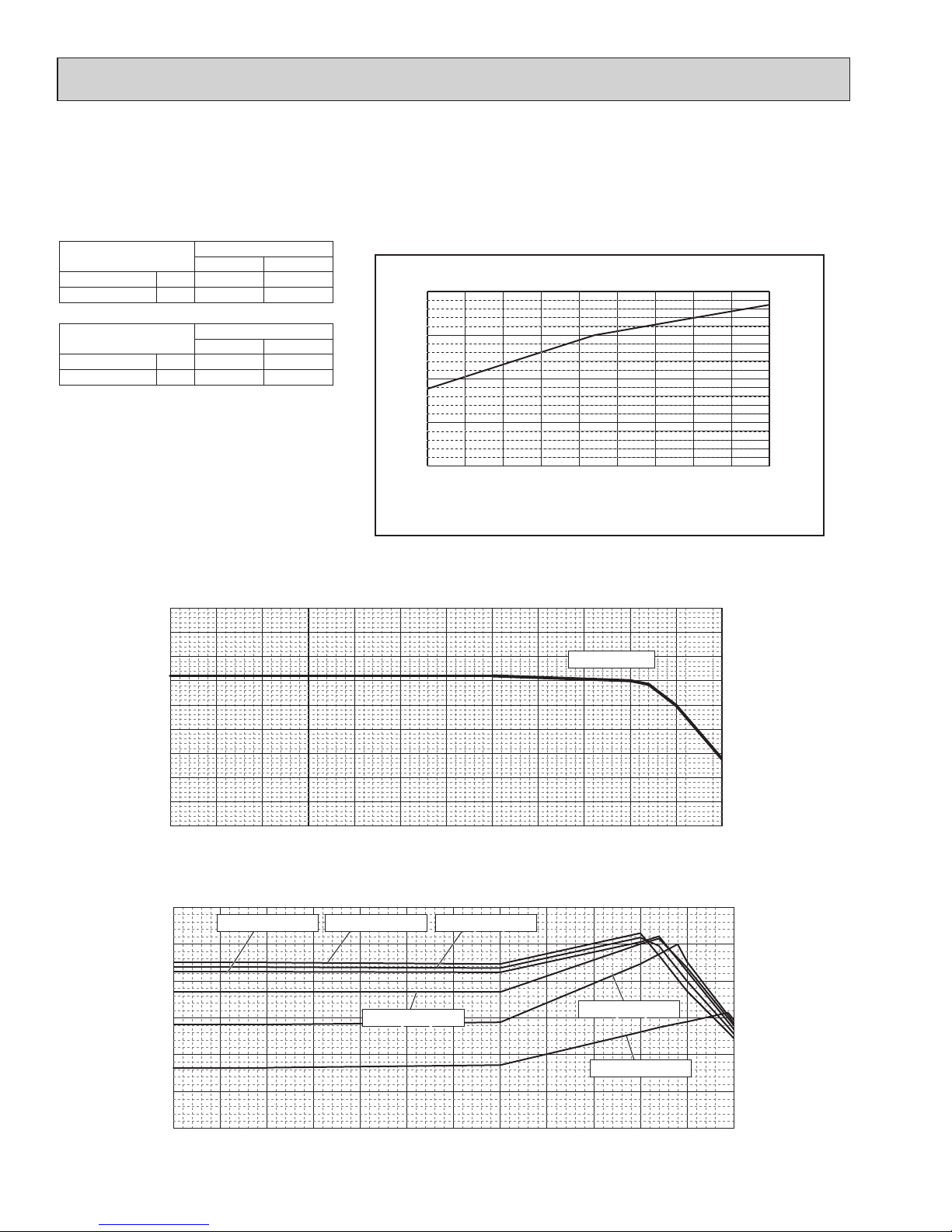
4-2. CORRECTING BY TEMPERATURE
15 16 17 18 19 20 21 22 23 24
59 60.8 62.6 64.4 66.2 68 69.8 71.6 73.4 75.2
0.4
0.6
0.8
1.0
1.2
Ratio of cooling capacity
Indoor Temperature
[°CW.B.]
[°FW.B.]
5 14
23 32 41 50 59 68 77 86 95 104 113
-15 -10
-5 0 5 10 15 20 25 30 35 40 45
0.4
0.5
0.6
0.7
0.8
0.9
1.0
1.1
1.2
1.3
Ratio of cooling capacity
Outdoor Temperature
67.0°F (19.4°C) W.B.
[°C W.B.]
[°F W.B.]
-15 -10
-5 0 5 10 15 20 25 30 35 40 45
5 14
23 32 41 50 59 68 77 86 95 104 113
0.0
0.2
0.4
0.6
0.8
1.0
1.2
Ratio of power input
Outdoor Temperature
[°C W.B.]
[°F W.B.]
68.0°F (20.0°C) W.B.68.0°F (20.0°C) W.B. 75.2°F (24.0°C) W.B.75.2°F (24.0°C) W.B.
71.6°F (22.0°C) W.B.71.6°F (22.0°C) W.B.
67.0°F (19.4°C) W.B.67.0°F (19.4°C) W.B.
64.4°F (18.0°C) W.B.64.4°F (18.0°C) W.B.
60.8°F (16.0°C) W.B.60.8°F (16.0°C) W.B.
MXZ-4C36/5C42/8C48NA(HZ), 8C60NA could have varied capacity at different designing temperature. Using the nominal
cooling/heating capacity value and the ratio below, the capacity can be observed at various temperature.
MXZ
4C36 5C42
Nominal cooling capacity
BTU/h 36,000 48,000
Input kW 2.57 3.13
Figure 7 Indoor unit temperature correction
To be used to correct indoor unit capacity only
Figure 8 Outdoor unit temperature correction
To be used to correct outdoor unit capacity only
<Cooling>
Indoor Temperature
Indoor Temperature
MXZ
8C48 8C60
Nominal cooling capacity
BTU/h 48,000 60,000
Input kW 4.00 4.80
OCH573C
Page 21
21
<Heating>
15 16 17 18 19 20 21 22 23 24 25 26 27
59 60.8 62.6 64.4 66.2 68 69.8 71.6 73.4 75.2 77 78.8 80.6
0.6
0.7
0.8
0.9
1.0
1.1
1.2
1.3
Ratio of heating capacity
Indoor Temperature
[°C W.B.]
[°F W.B.]
-25
-20 -15 -10 -5 0 5 10
15
-13
-4 5 14 23 3 41 50
59
0.4
0.5
0.6
0.7
0.8
0.9
1.0
1.1
1.2
1.3
1.4
Ratio of heating capacity
Outdoor Temperature
[°C W.B.]
[°F W.B.]
70.0°F (21.1°C) D.B.
-25
-20 -15 -10 -5 0 5 10
15
-13
-4 5 14 23 3 41 50
59
0.0
0.2
0.4
1.0
0.6
0.8
1.2
1.4
Ratio of power input
Outdoor Temperature
[°C W.B.]
[°F W.B.]
70.0°F (21.1°C) D.B.
60.8°F (16.0°C) D.B.
78.8°F (26.0°C) D.B.
Figure 9 Indoor unit temperature correction
To be used to correct indoor unit capacity only
Figure 10 Outdoor unit temperature correction
To be used to correct outdoor unit capacity only
MXZ
8C48NA 8C60NA
Nominal heating capacity
BTU/h 54,000 66,000
Input kW
4.22 5.67
Indoor Temperature
Indoor Temperature
OCH573C
Page 22
22
<Heating> (NAHZ)
15 16 17 18 19 20 21 22 23 24 25 26 27
59 60.8 62.6 64.4 66.2 68 69.8 71.6 73.4 75.2 77 78.8 80.6
0.6
0.7
0.8
0.9
1.0
1.1
1.2
1.3
Ratio of heating capacity
Indoor Temperature
[°C W.B.]
[°F W.B.]
-25
-20 -15 -10 -5 0 5 10
15
0.4
1.3
-13
-4 5 14 23 3 41 50
59
0.5
0.6
0.7
0.8
0.9
1.0
1.1
1.2
1.4
Ratio of heating capacity
Outdoor Temperature
[°C W.B.]
[°F W.B.]
70.0°F (21.1°C) D.B.
Ratio of power input
Outdoor intake air dry-bulb temperature
-13 -14 5 14 23 32 41 50 59
-25
-20 -15 -10 -5 0 5 10
15
0.0
0.2
0.4
0.6
0.8
1.0
1.2
1.4
1.6
1.8
2.0
[°C W.B.]
[°F W.B.]
60.8°F (16.0°C) W.B.
69.8°F (21.0°C) W.B.
78.8°F (26.0°C) W.B.
Figure 11 Indoor unit temperature correction
To be used to correct indoor unit capacity only
Figure 12 Outdoor unit temperature correction
To be used to correct outdoor unit capacity only
MXZ
4C36NAHZ 5C42NAHZ 8C48NAHZ
Nominal heating
capacity
BTU/h 45,000 48,000 54,000
Input kW
3.34 3.43 4.22
Indoor Temperature
Indoor Temperature
OCH573C
Page 23

23
Operation
Outdoor unit model
MXZ-4C36NAHZ MXZ-5C42NAHZ
Operating
conditions
Ambient
temperature
Indoor
DB/WB
80°F/67°F 70°F/60°F 80°F/67°F 70°F/60°F
Outdoor 95°F/75°F 47°F/43°F 95°F/75°F 47°F/43°F
Indoor unit
No. of connected units
Unit
4 4
No. of units in operation
4 4
Model — 09 × 4 09 × 2 + 12 ×2
Piping
Main pipe
m
9.84 (3) 9.84 (3)
Branch pipe 14.76 (4.5) 14.76 (4.5)
Total pipe length 68.90 (21) 68.90 (21)
Fan speed — Hi Hi
Amount of refrigerant
lb oz
(kg)
17 lb 7 oz (7.9) 17 lb 7 oz (7.9)
Outdoor unit
Electric current A 14.1 18.7 17.2 19.1
Voltage V 230 230
Compressor frequency Hz 59 74 70 80
LEV
opening
Indoor unit Pulse 112 128 129 128
Pressure High pressure/Low pressure
MPaG 2.57/0.98 2.78/0.64 2.72/0.80 2.80/0.56
PSIG 373/142 403/93 395/116 406/81
Temp. of
each section
Outdoor
unit
Discharge
°F
[°C]
143.8 [62.1] 151.5 [66.4] 148.6 [64.8] 145.8 [63.2]
Heat exchanger outlet 100.8 [38.2] 36.7 [2.6] 101.8 [38.8] 35.6 [2.0]
Accumulator inlet 50.5 [10.3] 36.1 [2.3] 49.5 [9.7] 34.9 [1.6]
Compressor inlet 47.1 [8.4] 34.0 [1.1] 45.3 [7.4] 32.7 [0.4]
Indoor unit
LEV inlet 70.0 [21.1] 103.5 [39.7] 83.7 [28.7] 100.2 [37.9]
Heat exchanger inlet 54.1 [12.3] 138.9 [59.4] 49.6 [9.8] 132.3 [55.7]
4-3. STANDARD OPERATION DATA (REFERENCE DATA)
Operation
Outdoor unit model
MXZ-8C48NA/NAHZ MXZ-8C60NA
Operating
conditions
Ambient
temperature
Indoor
DB/WB
80°F/67°F 70°F/60°F 80°F/67°F 70°F/60°F
Outdoor 95°F/75°F 47°F/43°F 95°F/75°F 47°F/43°F
Indoor unit
No. of connected units
Unit
4 5
No. of units in operation
4 5
Model — 12 × 4 09 × 3 + 15 + 18
Piping
Main pipe
m
9.84 (3) 9.84 (3)
Branch pipe 14.76 (4.5) 14.76 (4.5)
Total pipe length 68.90 (21) 83.79 (25.5)
Fan speed — Hi Hi
Amount of refrigerant
lb oz
(kg)
17 lb 7 oz (7.9) 20 lb (8.9)
Outdoor unit
Electric current A 22.1 21.9 20.4 24.4
Voltage V 230 230
Compressor frequency Hz 86 91 45 51
LEV
opening
Indoor unit Pulse 11 2 132 187 229
Pressure High pressure/Low pressure
MPaG 2.83/0.77 2.82/0.55 2.84/0.92 2.44/0.672
PSIG 410/112 409/80 412/134 354/97.5
Temp. of
each section
Outdoor
unit
Discharge
°F
[°C]
157.6 [69.8] 149.2 [65.1] 167 [75.0] 133.9 [56.6]
Heat exchanger outlet 105.6 [40.9] 34.3 [1.3] 98.8 [37.1] 51.1 [10.2]
Accumulator inlet 47.1 [8.4] 33.4 [0.8] 49.5 [9.7] 32.4 [0.2]
Compressor inlet 42.4 [5.8] 30.6 [−0.8] 72.5 [22.5] 31.6 [−0.2]
Indoor unit
LEV inlet 71.1 [21.7] 98.8 [37.1] 59.7 [15.4] 81.9 [27.7]
Heat exchanger inlet 47.5 [8.6] 134.6 [57.0] 52.5 [11.4] 104.2 [40.1]
OCH573C
Page 24
24
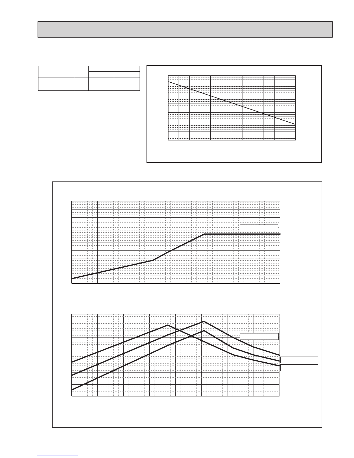
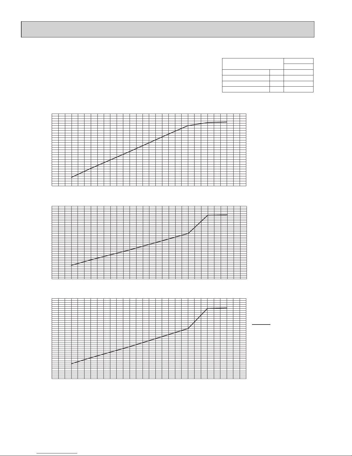
4-4. STANDARD CAPACITY DIAGRAM
Before calculating the sum of total capacity of indoor units, please convert the value into the kW model capacity following the formula on
"4-1. Method for obtaining system cooling and heating capacity".
4-4-1. MXZ-4C36NAHZ <cooling>
Ratio of capacity
Total capacity of indoor units (kBTU/h)
Total capacity of indoor units (kBTU/h)
Ratio of power inputRatio of current
Total capacity of indoor units (kBTU/h)
0
10
20
30
40 50
0.0
0.2
0.4
0.6
0.8
1.0
1.2
1.4
1.6
0 10 20
30
40 50
0.0
0.2
0.4
0.6
0.8
1.0
0 10 20
30
40 50
0.0
0.2
0.4
0.6
0.8
1.0
1.2
1.4
1.6
MXZ
4C36NAHZ
Nominal cooling capacity BTU/h 36,000
Input kW 2.57
Current (208V) A 12.8
Current (230V) A 11.6
208, 230 V
OCH573C
Page 25
25
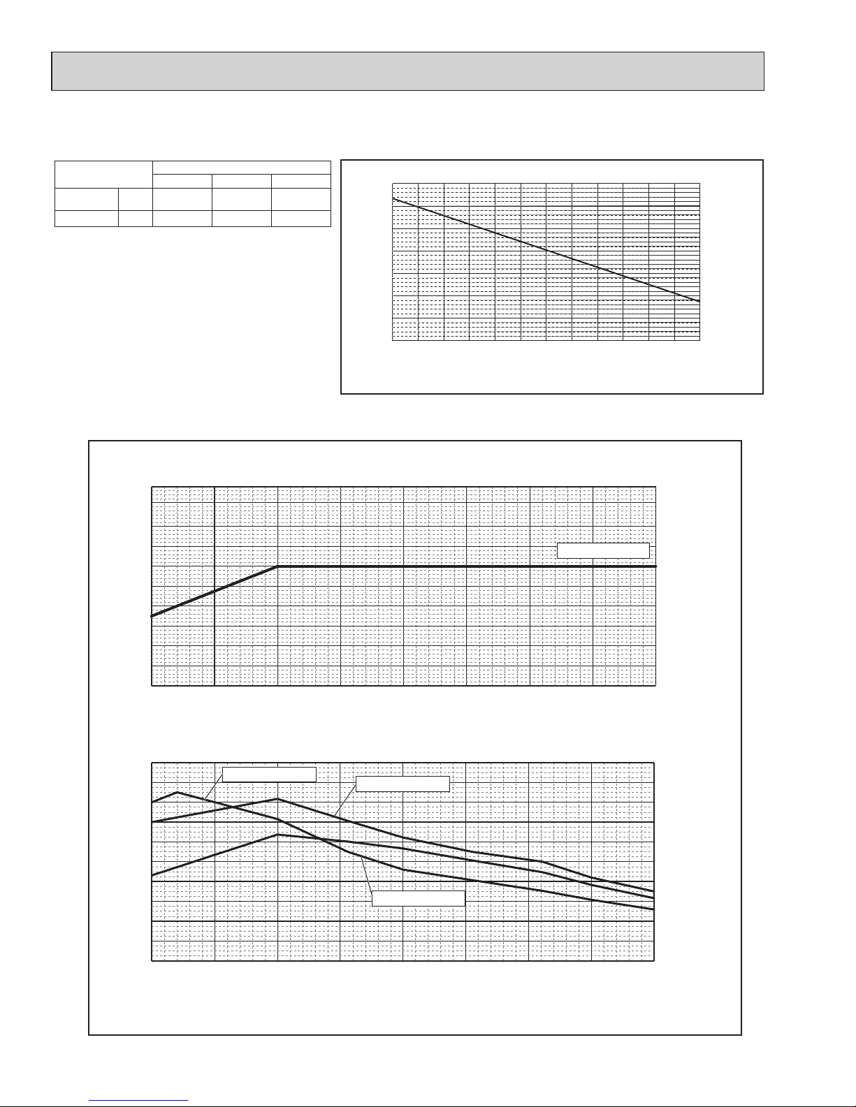
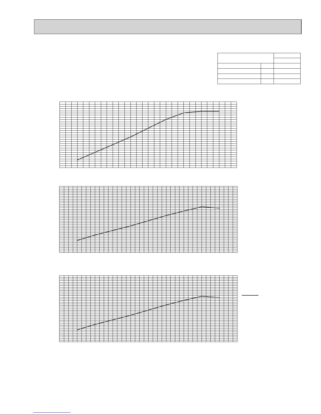
4-4-2. MXZ-4C36NAHZ <heating>
MXZ
4C36NAHZ
Nominal cooling capacity BTU/h 45,000
Input kW 3.34
Current (208V) A 16.4
Current (230V) A 14.8
Total capacity of indoor units (kBTU/h)
Total capacity of indoor units (kBTU/h)
Total capacity of indoor units (kBTU/h)
0
10
20
30
40 50
0.0
0.2
0.4
0.6
0.8
1.0
1.2
1.4
1.6
0 10 20
30
40 50
0.0
0.2
0.4
0.6
0.8
1.0
0 10 20
30
40 50
0.0
0.2
0.4
0.6
0.8
1.0
1.2
1.4
1.6
Ratio of capacity
Ratio of power inputRatio of current
208, 230 V
OCH573C
Page 26
26
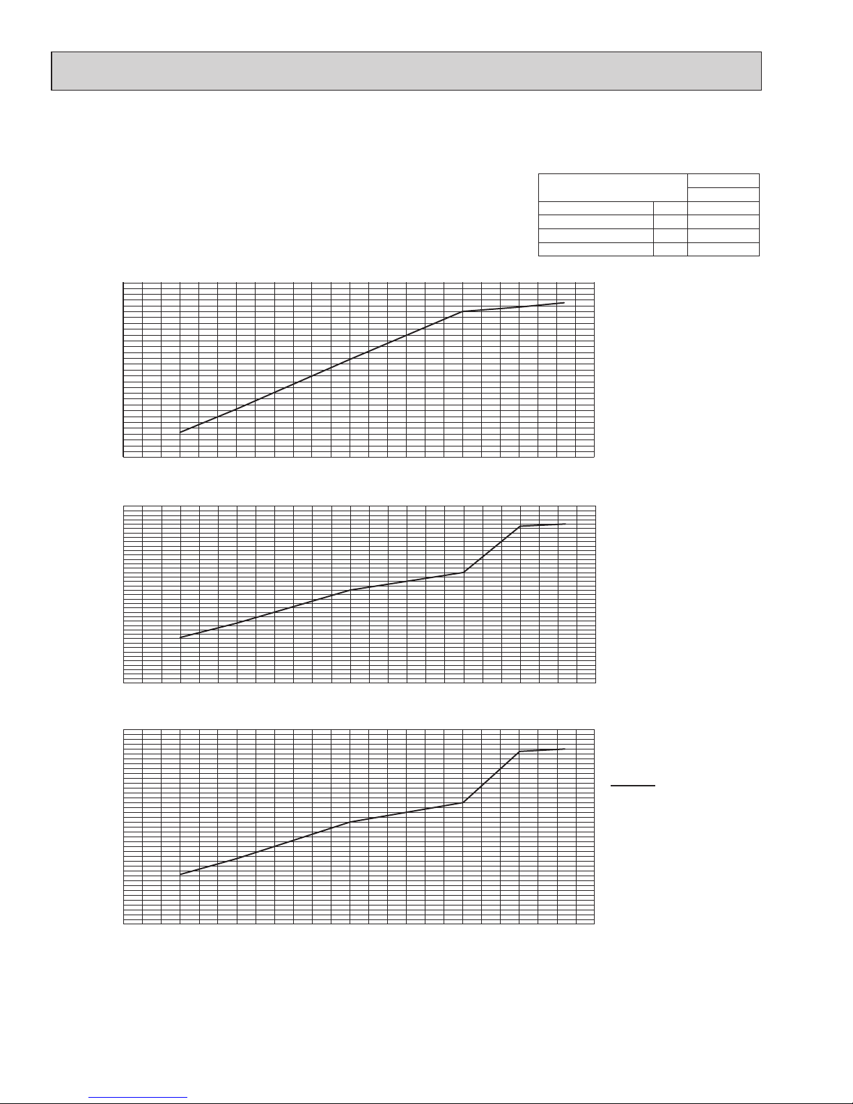
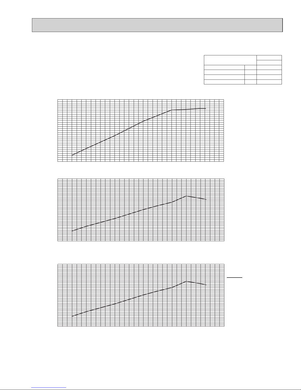
4-4-3. MXZ-5C42NAHZ <cooling>
Total capacity of indoor units (kBTU/h)
Total capacity of indoor units (kBTU/h)
Total capacity of indoor units (kBTU/h)
0
10
20
30
40 50
60
0.0
0.2
0.4
0.6
0.8
1.0
1.2
1.4
1.6
0 10 20
30
40 50
60
0.0
0.2
0.4
0.6
0.8
1.0
1.2
0 10 20
30
40 50
60
0.0
0.2
0.4
0.6
0.8
1.0
1.2
1.4
1.6
Ratio of capacity
Ratio of power inputRatio of current
MXZ
5C42NAHZ
Nominal cooling capacity BTU/h 42,000
Input kW 3.13
Current (208V) A 15.4
Current (230V) A 14.0
208, 230 V
OCH573C
Page 27
27
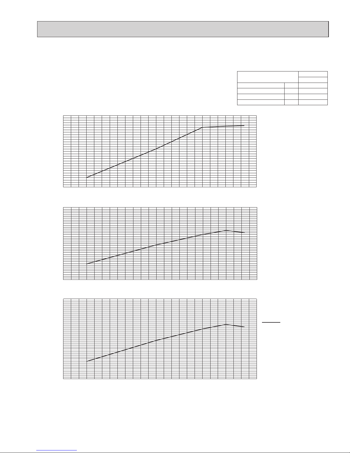
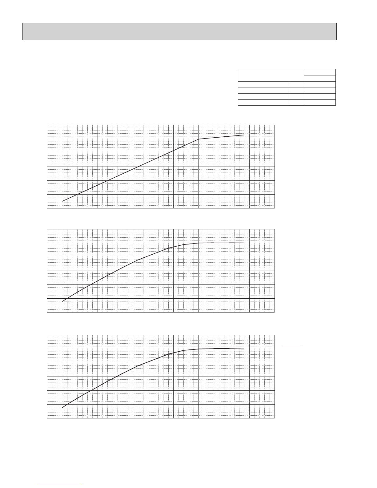
4-4-4. MXZ-5C42NAHZ <heating>
MXZ
5C42NAHZ
Nominal cooling capacity BTU/h 48,000
Input kW 3.43
Current (208V) A 16.8
Current (230V) A 15.2
Total capacity of indoor units (kBTU/h)
Total capacity of indoor units (kBTU/h)
Total capacity of indoor units (kBTU/h)
0 10 20
30
40 50
60
0.0
0.2
0.4
0.6
0.8
1.0
1.2
0.0 7.5 15.0 22.5
30.0
37.5 45.0 52.5
60.0
0.0
0.2
0.4
0.6
0.8
1.0
1.2
1.4
1.6
0.0 7.5 15.0 22.5
30.0
37.5 45.0 52.5
60.0
0.0
0.2
0.4
0.6
0.8
1.0
1.2
1.4
1.6
Ratio of capacity
Ratio of power inputRatio of current
208, 230 V
OCH573C
Page 28

28
4-4-5. MXZ-8C48NA MXZ-8C48NAHZ <cooling>
Total capacity of indoor units (kBTU/h)
Total capacity of indoor units (kBTU/h)
Total capacity of indoor units (kBTU/h)
Ratio of capacity
Ratio of power inputRatio of current
0 10 20
30
40 50
60
70
0.0
0.2
0.4
0.6
0.8
1.0
1.2
0 10 20 30 40 50
60
70
0.0
0.2
0.4
0.6
0.8
1.0
1.2
1.4
1.6
0 10 20 30 40 50
60
70
0.0
0.2
0.4
0.6
0.8
1.0
1.2
1.4
1.6
MXZ
8C48NAHZ
Nominal cooling capacity BTU/h 48,000
Input kW 4.00
Current (208V) A 19.5
Current (230V) A 17.6
208, 230 V
OCH573C
Page 29
29
4-4-6. MXZ-8C48NA MXZ-8C48NAHZ <heating>
Total capacity of indoor units (kBTU/h)
Total capacity of indoor units (kBTU/h)
Total capacity of indoor units (kBTU/h)
Ratio of capacity
Ratio of power inputRatio of current
0 10 20
30
40 50
60
70
0.0
0.2
0.4
0.6
0.8
1.0
1.2
0 10 20
30
40 50
60
70
0.0
0.2
0.4
0.6
0.8
1.0
1.2
1.4
1.6
0 10 20
30
40 50
60
70
0.0
0.2
0.4
0.6
0.8
1.0
1.2
1.4
1.6
MXZ
8C48NA(HZ)
Nominal cooling capacity BTU/h 54,000
Input kW 4.22
Current (208V) A 20.5
Current (230V) A 18.6
208, 230 V
OCH573C
Page 30
30
4-4-7. MXZ-8C60NA <cooling>
0.0 10.0 20.0 30.0 40.0 50.0 60.0 70.0 80.0 90.0
0.0
0.2
0.4
0.6
0.8
1.0
1.2
0.0 10.0 20.0 30.0 40.0 50.0 60.0 70.0 80.0 90.0
0.0
0.2
0.4
0.6
0.8
1.0
0.0 10.0 20.0 30.0 40.0 50.0 60.0 70.0 80.0 90.0
0.0
0.2
0.4
0.6
0.8
1.0
Total capacity of indoor units(kBTU/h)
Total capacity of indoor units(kBTU/h)
Total capacity of indoor units(kBTU/h)
Ratio of capacity
Ratio of power inputRatio of current
MXZ
8C60NA
Nominal cooling capacity BTU/h 60,000
Input kW 4.80
Current (208V) A 24.1
Current (230V) A 21.8
208, 230 V
OCH573C
Page 31

31
4-4-8. MXZ-8C60NA <heating>
0.0 10.0 20.0 30.0 40.0 50.0 60.0 70.0 80.0 90.0
0.0
0.2
0.4
0.6
0.8
1.0
1.2
0.0 10.0 20.0 30.0 40.0 50.0 60.0 70.0 80.0 90.0
0.0
0.2
0.4
0.6
0.8
1.0
1.2
0.0 10.0 20.0 30.0 40.0 50.0 60.0 70.0 80.0 90.0
0.0
0.2
0.4
0.6
0.8
1.0
1.2
208 V, 230 V
Total capacity of indoor units(kBTU/h)
Total capacity of indoor units(kBTU/h)
Total capacity of indoor units(kBTU/h)
Ratio of capacity
Ratio of power inputRatio of current
MXZ
8C60NA
Nominal cooling capacity BTU/h 66,000
Input kW 5.67
Current (208V) A 28.5
Current (230V) A 25.7
208, 230 V
OCH573C
Page 32

32
4-5.
CORRECTING CAPACITY FOR CHANGES IN THE LENGTH OF REFRIGERANT PIPING
(1) During cooling, obtain the ratio (and the equivalent piping length) of the outdoor units rated capacity and the total in-use
indoor capacity, and find the capacity ratio corresponding to the standard piping length from Figure 13 to 18. Then multiply by the cooling capacity from Figure 7 and 8 in "4-2. CORRECTION BY TEMPERATURE" to obtain the actual capacity.
(2) During heating, find the equivalent piping length, and find the capacity ratio corresponding to standard piping length from
Figure 17. Then multiply by the heating capacity from Figure 9 to 12 in "4-2. CORRECTION BY TEMPERATURE" to
obtain the actual capacity.
(1) Capacity Correction Curve
0 20 40 60 80 100 120 140 160 180 200 220 240 260
0.70
0.75
0.80
0.85
0.90
0.95
1.00
0 20 40 60 80 100 120 140 160 180 200 220 240 260
0.70
0.75
0.80
0.85
0.90
0.95
1.00
18 [kBTU/h]
27 [kBTU/h]
36 [kBTU/h]
Capacity ratio
Piping equivalent length (ft)
Total capacity of indoor unit
Total capacity of indoor unit
Capacity ratio
Piping equivalent length (ft)
46.8 [kBTU/h]
21 [kBTU/h]
31.5 [kBTU/h]
42 [kBTU/h]
54.6 [kBTU/h]
Figure 13 MXZ-4C36NAHZ <Cooling>
Figure 14 MXZ-5C42NAHZ <Cooling>
OCH573C
Page 33

33
0 20 40 60 80 100 120 140 160 180 200 220 240 260
0.70
0.75
0.80
0.85
0.90
0.95
1.00
Total capacity of indoor unit
Capacity ratio
Piping equivalent length (ft)
24 [kBTU/h]
36 [kBTU/h]
48 [kBTU/h]
62.4 [kBTU/h]
0 20 40 60 80 100 120 140 160 180 200 220 240 260
0.70
0.75
0.80
0.85
0.90
0.95
1.00
Total capacity of indoor unit
Capacity ratio
Piping equivalent length (ft)
30 [kBTU/h]
45 [kBTU/h]
60 [kBTU/h]
78 [kBTU/h]
Figure 15 MXZ-8C48NA <Cooling>
Figure 16 MXZ-8C60NA <Cooling>
OCH573C
Page 34

34
Figure 17 MXZ-4C36NAHZ/5C42NAHZ/8C48NA <Heating>
Figure 18 MXZ-8C60NA <Heating>
(2) Method for Obtaining the Equivalent Piping Length
Equivalent length for type P60 = (length of piping to farthest indoor unit) + (0.3 o number of bends in the piping) (m)
Length of piping to farthest indoor unit: type P60.....80 m
4-5-1. Correction of Heating Capacity for Frost and Defrosting
If heating capacity has been reduced due to frost formation or defrosting, multiply the capacity by the appropriate correction
factor from the following table to obtain the actual heating capacity.
Correction factor diagram
Outdoor Intake temperature <W.B.°F (°C)>
43(6) 39(4) 36(2) 32(0) 28(−2) 25(−4) 21(−6) 18(−8) 14(−10) 5(−15) −4(−20) −13(−25)
Correction factor
1.0 0.98 0.89 0.88 0.89 0.9 0.95 0.95 0.95 0.95 0.95 0.95
0 20 40 60 80 100 120 140 160 180 200 220 240 260
0.70
0.75
0.80
0.85
0.90
0.95
1.00
Total capacity of indoor unit
Capacity ratio
Piping equivalent length (ft)
0 20 40 60 80 100 120 140 160 180 200 220 240 260
0.70
0.75
0.80
0.85
0.90
0.95
1.00
Total capacity of indoor unit
Capacity ratio
Piping equivalent length (ft)
OCH573C
Page 35

35
4-6. NOISE CRITERION CURVES
5 ft
(1.5 m)
3.3 ft (1 m)
MICROPHONE
UNIT
GROUND
90
80
70
60
50
40
30
20
10
63 125 250 500 1000 2000 4000 8000
APPROXIMATE
THRESHOLD OF
HEARING FOR
CONTINUOUS
NOISE
OCTAVE BAND SOUND PRESSURE LEVEL, dB (0 dB = 0.0002 µbar)
BAND CENTER FREQUENCIES, Hz
NC-60
NC-50
NC-40
NC-30
NC-20
NC-70
MXZ-5C42NAHZ
MXZ-5C42NAHZ-U1
COOLING
MODE
HEATING
50
SPL(dB)
54
LINE
90
80
70
60
50
40
30
20
10
63 125 250 500 1000 2000 4000 8000
APPROXIMATE
THRESHOLD OF
HEARING FOR
CONTINUOUS
NOISE
OCTAVE BAND SOUND PRESSURE LEVEL, dB (0 dB = 0.0002 µbar)
BAND CENTER FREQUENCIES, Hz
NC-60
NC-50
NC-40
NC-30
NC-20
NC-70
MXZ-8C48NA
MXZ-8C48NA-U1
MXZ-8C48NAHZ
MXZ-8C48NAHZ-U1
COOLING
MODE
HEATING
51
SPL(dB)
54
LINE
90
80
70
60
50
40
30
20
10
63 125 250 500 1000 2000 4000 8000
APPROXIMATE
THRESHOLD OF
HEARING FOR
CONTINUOUS
NOISE
OCTAVE BAND SOUND PRESSURE LEVEL, dB (0 dB = 0.0002 µbar)
BAND CENTER FREQUENCIES, Hz
NC-60
NC-50
NC-40
NC-30
NC-20
NC-70
MXZ-4C36NAHZ
MXZ-4C36NAHZ-U1
COOLING
MODE
HEATING
49
SPL(dB)
53
LINE
90
80
70
60
50
40
30
20
10
63 125 250 500 1000 2000 4000 8000
APPROXIMATE
THRESHOLD OF
HEARING FOR
CONTINUOUS
NOISE
OCTAVE BAND SOUND PRESSURE LEVEL, dB (0 dB = 0.0002 µbar)
BAND CENTER FREQUENCIES, Hz
NC-60
NC-50
NC-40
NC-30
NC-20
NC-70
MXZ-8C60NA-U1
COOLING
MODE
HEATING
58
SPL(dB)
59
LINE
OCH573C
Page 36

36
5 OUTLINES AND DIMENSIONS
5-1. OUTDOOR UNIT
MXZ-4C36NAHZ MXZ-5C42NAHZ MXZ-8C48NAHZ MXZ-8C48NA
Air Discharge
Rear Air Intake
Side Air Intake
2-12×36 Oval holes
(Foundation Bolt M10<W3/8>)
2-U Shaped notched holes
(Foundation Bolt M10<W3/8>)
Installation Feet
42<1-21/32>
56<2-7/32>
370 <14-9/16>
25<1>
417 <16-13/32>
70
<2-3/4>
28<1-3/32>
225
<8-27/32>
225
<8-27/32>
330 <13>
600
<23-5/8>
19<3/4>
56<2-7/32>
33.2 <1-5/16>053<2-3/32>
1/2 inch Conduit
attachment
{
22.2<7/8>
{
34.5<1-23/64>
When installing the conduit.
Set the attachment to the
inner side of each panel.
1 inch Conduit
attachment
Scale 1:5
24.7 <31/32>
5<3/16>
60<2-3/8> 24 <15/16>
101.5 <4>
Ground for the
branch box
power supply
For the
power supply
For the
branch box
power supply
For the
transmission line
For concentration
control
Terminal connection
From left to right
Handle for moving
Ground for the transmission line
Ground for concentration control
1
2
Handle for moving
Service panel
Ground for the power supply
("GR"marking position)
632 <24-7/8>
1338 <52-11/16>
26<1-1/32>
1050 <41-11/32>
1067 <42>
426 <16-25/32> *
1
369 <14-17/32>
362 <14-1/4>
510 <20-3/32> *
1
Rear piping cover
Front piping cover
Air intake
Bottom piping hole
(Knockout)
Drain hole
(5-
{
33<1-5/16>)
160
<6-5/16>
110 <4-11/32>
160
<6-5/16>
160
<6-5/16>
136
<5-11/32>
86<3-3/8>
81<3-3/16>
45<1-25/32>
154
<6-1/16>
Right piping hole
(Knockout)
Conduit hole
(
{
24<15/16>Knockout)
Conduit hole
(
{
37<1-15/32>Knockout)
Right trunking hole
(Knockout)
92<3-5/8>
60<2-3/8>
5<3/16>
60<2-3/8>
55<2-3/16>
53<2-3/32>
92
<3-5/8>
26<1-1/32> 27 <1-1/16>
29<1-5/32>
73<2-7/8>
{
92
<3-5/8>
Min. 150mm<5-29/32>Min. 1000mm<39-3/8>
Side Air Intake
Conduit hole
(
{
37<1-15/32>Knockout)
Front trunking hole
(Knockout)
Front piping hole
(Knockout)
Conduit hole
(
{
24<15/16>Knockout)
55<2-3/16>
27<1-1/16>
92<3-5/8>
75<2-15/16>
73<2-7/8>26<1-1/32>
55<2-3/16>
60
<2-3/8>
5
<3/16>
60<2-3/8>
{
92
<3-5/8>
FREE
Min. 15mm<19/32>
Min. 15mm<19/32>
Handle for
moving
Handle for
moving
Rear Air Intake
Conduit hole
(
{
24<15/16>Knockout)
Conduit hole
(
{
37<1-15/32>Knockout)
Rear trunking hole
(Knockout)
Rear piping hole
(Knockout)
75<2-15/16>
60<2-3/8>
92<3-5/8>
73<2-7/8>
26<1-1/32>
27<1-1/16>
55<2-3/16>
55<2-3/16>
5<3/16>
60<2-3/8>
{
92
<3-5/8>
1……
Refrigerant GAS pipe connection (FLARE){15.88 (5/8F)
2……
Refrigerant LIQUID pipe connection (FLARE){9.52 (3/8F)
*
1
.......
Indication of STOP VALVE connection location.
Piping and wiring connections
can be made from 4 directions:
FRONT, Right, Rear and Below.
4 PIPING-WIRING DIRECTIONS
3 FOUNDATION BOLTS
2 SERVICE SPACE
1 FREE SPACE (Around the unit)
Please secure the unit firmly
with 4 foundation (M10<W3/8>) bolts.
(Bolts and washers must be
purchased locally.)
Dimensions of space needed
for service access are
shown in the below diagram.
The diagram below shows a basic example.
Explantion of particular details are
given in the installation manuals etc.
Max.
<Foundation bolt height>
FOUNDATION
Service space
Min.
Min.
Min.
Min.
15<19/32>
500
<19-11/16>
500
<19-11/16>
150
<5-29/32>
30<1-3/16>
Piping Knockout Hole Details
Example of Notes
mm<inch>
Unit: mm <inch>
OCH573C
Page 37

37
MXZ-4C36NAHZ-U1 MXZ-5C42NAHZ-U1 MXZ-8C48NAHZ-U1 MXZ-8C48NA-U1
2-12×36 Oval holes
(Foundation Bolt M10<W3/8>)
2-U Shaped notched holes
(Foundation Bolt M10<W3/8>)
Installation Feet
Air Discharge
Rear Air Intake
Side Air Intake
417 <16-13/32>
70
<2-3/4>
225
<8-27/32>
600
<23-5/8>
225
<8-27/32>
330 <13>25<1>
42
<1-21/32>
60.5
<2-3/8>
28 <1-3/32> 370 <14-9/16> 19 <3/4>
39.5 <1-9/16>
56 <2-7/32>
53 <2-3/32>
0
Drain hole
(5-
{
33<1-5/16>)
Bottom piping hole
(Knock-Out)
154
<6-1/16>
136
<5-11/32>
45
<1-25/32>
110
<4-11/32>
160
<6-5/16>
160
<6-5/16>
160
<6-5/16>
81
<3-3/16>
86 <3-3/8>
Rear piping cover
Front piping cover
Air intake
Ground for the
branch box
power supply
For the
power supply
For the
branch box
power supply
For the
transmission line
For concentration
control
Terminal connection
From left to right
Handle for moving
Ground for the transmission line
Ground for concentration control
1
2
Handle for moving
Service panel
Ground for the power supply
("GR"marking position)
26 <1-1/32>
1050 <41-11/32>
362 <14-1/4>
1338 <52-11/16>
632 <24-7/8>369 <14-17/32>
485 <19-3/32>
426 <16-25/32>
1067 <42>
Side Air Intake
Handle for
moving
Rear Air Intake
Handle for
moving
{15.88 (5/8F)
{9.52(3/8F)
1
2
Example of Notes
Rear piping hole
(Knock-Out)
Rear trunking hole
(Knock-Out)
Conduit hole
(
{
37<1-15/32>Knock-Out)
Conduit hole
(
{
24<15/16>Knock-Out)
60<2-3/8>
5<3/16>
55<2-3/16>
55<2-3/16>27<1-1/16>
26<1-1/32> 73<2-7/8>
92<3-5/8>
60<2-3/8>
75<2-15/16>
{
92
<3-5/8>
Conduit hole
(
{
24<15/16>Knock-Out)
Front piping hole
(Knock-Out)
Front trunking hole
(Knock-Out)
Conduit hole
(
{
37<1-15/32>Knock-Out)
60<2-3/8>
5
<3/16>
60
<2-3/8>
55<2-3/16>
26<1-1/32> 73<2-7/8>
75<2-15/16>
92<3-5/8>
27<1-1/16> 55<2-3/16>
{
92
<3-5/8>
Right trunking hole
(Knock-Out)
Conduit hole
(
{
37<1-15/32>Knock-Out)
Conduit hole
Right piping hole
(Knock-Out)
73<2-7/8>
29<1-5/32>
27<1-1/16>26<1-1/32>
92
<3-5/8>
53<2-3/32>
55<2-3/16>
60<2-3/8>
5<3/16>
60<2-3/8>
92<3-5/8>
{
92
<3-5/8>
Scale 1:5
1 inch Conduit
attachment
When installing the conduit.
Set the attachment to the
inner side of each panel.
{
34.5<1-23/64>
{
22.2<7/8>
1/2 inch Conduit
attachment
101.5 <4>
24<15/16>60 <2-3/8>
5<3/16>
24.7 <31/32>
mm<inch>
Piping Knock-Out Hole Details
Min.
Min.
Min.
Min.
Service space
FOUNDATION
<Foundation bolt height>
Max.
Dimensions of space needed
for service access are
shown in the below diagram.
Please secure the unit firmly
with 4 foundation (M10<W3/8>) bolts.
(Bolts and washers must be
purchased locally.)
Piping and wiring connections
can be made from 4 directions:
FRONT, Right, Rear and Below.
1 FREE SPACE (Around the unit)
2 SERVICE SPACE
3 FOUNDATION BOLTS
4 PIPING-WIRING DIRECTIONS
30<1-3/16>
150
<5-29/32>
500
<19-11/16>
500
<19-11/16>
15<19/32>
Min. 15mm<19/32>
Min. 15mm<19/32>
FREE
Min. 1000mm<39-3/8> Min. 150mm<5-29/32>
The diagram below shows a basic example.
Explantion of particular details are
given in the installation manuals etc.
(
{
24<15/16>Knock-Out)
Unit: mm <inch>
OCH573C
Page 38

38
MXZ-8C60NA-U1
Ground for the power supply
("GR"marking position)
Service panel
Handle for moving
2
1
Ground for the transmission line
Ground for concentration control
Handle for moving
From left to right
Terminal connection
For concentration
control
For the
transmission line
For the
branch box
power supply
For the
power supply
Ground for the
branch box
power supply
1067 <42>
450 <17-23/32>
393 <15-15/32>
1338 <52-11/16>
632 <24-7/8>369 <14-17/32>
26 <1-1/32>
362 <14-1/4>
1050 <41-11/32>
Rear Air Intake
Air Discharge
Side Air Intake
Installation Feet
2-U Shaped notched holes
(Foundation Bolt M10<W3/8>)
2-12×36 Oval holes
(Foundation Bolt M10<W3/8>)
42
<1-21/32>
60.5
<2-3/8>
417 <16-13/32>
19 <3/4>370 <14-9/16>
28 <1-1/32>
70
<2-3/4>
25 <1> 330 <13>
225
<8-27/32>
600
<23-5/8>
225
<8-27/32>
53 <2-3/32>
56 <2-7/32>
39.5 <1-9/16>
0
Bottom piping hole
(Knock-Out)
Drain hole
(5-
{33<1-5/16>)
154
<6-1/16>
136
<5-11/32>
45
<1-25/32>
110
<4-11/32>
160
<6-5/16>
160
<6-5/16>
160
<6-5/16>
86 <3-3/8>
81
<3-3/16>
Air intake
Front piping cover
Rear piping cover
Side Air Intake
Rear Air Intake
Handle for
moving
Handle for
moving
2
1
{19.05 (3/4F)
{9.52(3/8F)
Example of Notes
1/2 inch Conduit
attachment
{
22.2<7/8>
{
34.5<1-23/64>
When installing the conduit.
Set the attachment to the
inner side of each panel.
1 inch Conduit
attachment
Scale 1:5
24.7 <31/32>
5<3/16>
60<2-3/8> 24 <15/16>
101.5 <4>
Right piping hole
(Knock-Out)
Conduit hole
(
{
24<15/16>Knock-Out)
Conduit hole
(
{
37<1-15/32>Knock-Out)
Right trunking hole
(Knock-Out)
92<3-5/8>
60<2-3/8>
5<3/16>
60<2-3/8>
55<2-3/16>
53<2-3/32>
92
<3-5/8>
26<1-1/32> 27 <1-1/16>
29<1-5/32>
73<2-7/8>
{
92
<3-5/8>
Conduit hole
(
{
37<1-15/32>Knock-Out)
Front trunking hole
(Knock-Out)
Front piping hole
(Knock-Out)
Conduit hole
(
{
24<15/16>Knock-Out)
55<2-3/16>27<1-1/16>
92<3-5/8>
75<2-15/16>
73<2-7/8>26 <1-1/32>
55<2-3/16>
60
<2-3/8>
5
<3/16>
60<2-3/8>
{
92
<3-5/8>
Conduit hole
(
{
24<15/16>Knock-Out)
Conduit hole
(
{
37<1-15/32>Knock-Out)
Rear trunking hole
(Knock-Out)
Rear piping hole
(Knock-Out)
75<2-15/16>
60<2-3/8>
92<3-5/8>
73<2-7/8>26<1-1/32>
27<1-1/16> 55 <2-3/16>
55<2-3/16>
5<3/16>
60<2-3/8>
{
92
<3-5/8>
Piping Knock-Out Hole Details
mm<inch>
Min. 150mm<5-29/32>Min. 1000mm<39-3/8>
FREE
Min. 15mm<19/32>
Min. 15mm<19/32>
Piping and wiring connections
can be made from 4 directions:
FRONT, Right, Rear and Below.
4 PIPING-WIRING DIRECTIONS
3 FOUNDATION BOLTS
2 SERVICE SPACE
1 FREE SPACE (Around the unit)
Please secure the unit firmly
with 4 foundation (M10<W3/8>) bolts.
(Bolts and washers must be
purchased locally.)
Dimensions of space needed
for service access are
shown in the below diagram.
The diagram below shows a basic example.
Explantion of particular details are
given in the installation manuals etc.
Max.
<Foundation bolt height>
FOUNDATION
Service space
Min.
Min.
Min.
Min.
15<19/32>
500
<19-11/16>
500
<19-11/16>
150
<5-29/32>
30<1-3/16>
*1
Unit: mm <inch>
OCH573C
Page 39

39
Unit: mm <inch>
5-2. BRANCH BOX
PAC-MKA50BC
PAC-MKA51BC
PAC-MKA30BC
PAC-MKA31BC
E D C B A
E D C B A
TO INDOOR UNIT
90
〈3-17/32〉
70
〈2-3/4〉
70
〈2-3/4〉
70
〈2-3/4〉
70
〈2-3/4〉
450〈17-23/32〉
67〈2-9/16〉
25
〈1〉
25
〈1〉
25
〈1〉
25
〈1〉
25
〈1〉
65
〈2-9/16〉
47〈1-27/32〉
170〈6-11/16〉
72
〈2-27/32〉
5-
[
22〈7/8〉
(1:2)
When installing the conduit.
Set the attachment to the
inner side of each panel.
1/2 inch Conduit
attachment
129〈5-3/32〉
17〈21/32〉
48〈1-7/8〉 48〈1-7/8〉
24
〈15/16〉
66〈2-19/32〉
15〈19/32〉
12〈15/32〉
105
〈4-1/8〉
24
〈15/16〉
58〈2-9/32〉
20
〈25/32〉
28
〈1-3/32〉
SUSPENSION BOLT PITCH
SUSPENSION BOLT PITCH
320〈12-19/32〉
12〈1/2〉
24〈1〉
402〈15-13/16〉
5-ELECTRIC WIRE INLET
CONDUIT PLATE
CONTROL COVER
SERVICE PANEL
(for LEV, THERMISTOR)
TO OUTDOOR UNIT
40〈1-17/32〉280〈11-1/32〉
83
〈3-9/32〉
96
〈3-25/32〉
112
〈4-3/8〉
70
〈2-3/4〉
87
〈3-7/16〉
EDCBA
LIQUID PIPE
TO OUTDOOR UNIT
5/8F1/2F3/8F3/8F
3/8F
3/8F
3/8F1/4F1/4F1/4F1/4F1/4F
REFRIGERANT PIPE FLARED CONNECTION
GAS PIPE
SUSPENSION BOLT : W3/8(M10)
TB3B TB3D
TB3A TB3C TB3E
TB5
TB2B
TERMINAL BLOCK
TO OUTDOOR UNIT
TERMINAL BLOCK
TO INDOOR UNIT
TERMINAL BLOCK
TO M-NET UNIT
Unit: inch
TO INDOOR UNIT
A
ABC
B
C
CAP
CAP
25
〈1〉
72
〈2-27/32〉
90
〈3-17/32〉
170〈6-11/16〉
47〈1-27/32〉
65
〈2-9/16〉
25
〈1〉
25
〈1〉
70
〈2-3/4〉
70
〈2-3/4〉
209〈8-7/32〉
450〈17-23/32〉
SUSPENSION BOLT PITCH
SUSPENSION BOLT PITCH
320〈12-19/32〉
402〈15-13/16〉
24〈1〉
12〈1/2〉
1/2 inch Conduit
attachment
When installing the conduit.
Set the attachment to the
inner side of each panel.
(1:2)
5-{ 22〈7/8〉
28
〈1-3/32〉
20
〈25/32〉
58〈2-9/32〉
24
〈15/16〉
105
〈4-1/8〉
12〈15/32〉
15〈19/32〉
66〈2-19/32〉
24
〈15/16〉
48〈1-7/8〉48〈1-7/8〉
17〈21/32〉
129〈5-3/32〉
5-ELECTRIC WIRE INLET
CONDUIT PLATE
CONTROL COVER
TO OUTDOOR UNIT
SERV ICE PANEL
(for LEV, THERMISTOR)
40〈1-17/32〉
280〈11-1/32〉
87
〈3-7/16〉70〈2-3/4〉
83
〈3-9/32〉
96
〈3-25/32〉
112
〈4-3/8〉
TERMINAL BLOCK
TO M-NET UNIT
TERMINAL BLOCK
TO INDOOR UNIT
TERMINAL BLOCK
TO OUTDOOR UNIT
TB2B
TB5
TB3B
TB3CTB3A
SUSPENSION BOLT : W3/8(M10)
GAS PIPE
REFRIGERANT PIPE FLARED CONNECTION
1/4F 1/4F 1/4F 3/8F
3/8F
3/8F
3/8F 5/8F
TO OUTDOOR UNIT
LIQUID PIPE
A B C
Unit: inch
OCH573C
Page 40

40
6 WIRING DIAGRAM
6-1. OUTDOOR UNIT
MXZ-4C36NAHZ MXZ-5C42NAHZ MXZ-8C48NAHZ
MODELS
MXZ-4C36NAHZ
MXZ-5C42NAHZ
MXZ-8C48NAHZ
SW4
※1 MODEL SELECTION
The black square( )indicates a switch position.
ON
OFF
1 2 3 4 5 6
ON
OFF
1 2 3 4 5 6
ON
OFF
1 2 3 4 5 6
SW2 SW8
ON
OFF
1 2
ON
OFF
1 2
ON
OFF
1 2
ON
OFF
5 6
ON
OFF
5 6
ON
OFF
5 6
SYMBOL NAME SYMBOL NAME SYMBOL NAME
TB1 Terminal Block 〈Power Supply〉
TB1B Terminal Block 〈Branch Box〉
TB3 Terminal Block
〈
Branch box/Outdoor Transmission Line
〉
Terminal Block
〈
Centralized Control Transmission Line
〉
TB7
FUSE1,FUSE2
Fuse 〈
T20AL250V
〉
MC Motor For Compressor
MF1,MF2 Fan Motor
21S4 Solenoid Valve〈Four-Way Valve〉
SV1
Solenoid Valve〈Bypass Valve〉
SV2
Solenoid Valve〈Switching Valve〉
BH Base heater
TH3
Thermistor〈Outdoor Liquid Pipe〉
TH2
Thermistor〈Hic Pipe〉
TH4
Thermistor〈Compressor〉
TH6
Thermistor〈Suction Pipe〉
TH7 Thermistor〈Ambient〉
63H High Pressure Switch
63HS High Pressure Sensor
63LS Low Pressure Sensor
DCL
P.B. Power Circuit Board
Connection Terminal〈Ground〉
Connection Terminal〈U/V/W-Phase〉
U/V/W
MULTI.B.
Fuse〈T6,3AL250V〉
F1,F2
Switch〈Display Selection〉
SW1
Switch〈Function Selection〉
SW2
Switch〈Test Run〉
SW3
Switch〈Model Selection〉
SW4
Switch〈Function Selection〉
SW5
Switch〈Function Selection〉
SW6
Switch〈Model Selection〉
SW8
Switch〈Function Selection〉
SW9
Switch〈Unit Address Selection, 1st digit〉
SWU1
Switch〈Unit Address Selection, 2nd digit〉
SWU2
LED〈Operation Inspection Display〉
LED1,LED2
LED〈Power Supply to Main Microcomputer〉
LED3
Controller Circuit Board
Connector〈Base heater〉
SS
Connector〈Connection For Option〉
CN3D
Connector〈
Branch box/Outdoor Transmission Line
〉
CNS1
Connector〈
Centralized Control Transmission Line
〉
CNS2
Connector〈Connection For Option〉
CN3S
Connector〈Connection For Option〉
CN3N
Connector〈Connection For Option〉
CN51
Relay
X501〜505
M-NET P.B.
ConnectionTerminal〈Ground〉
M-NET Power Circuit Board
TB1
Connection Terminal〈L-Phase〉
LI
Connection Terminal〈N-Phase〉
NI
EI,E2,E3,E4
Power Module
IGBT
Connection Terminal〈Reactor〉
DCL1,DCL2
Reactor
LEV-A,LEV-B
Electronic Expansion Valve
Switch〈Function Selection〉
SW7
TH8 Thermistor〈Heat Sink〉
RED
RED
YLW
YLW
P. B.
BLK
WHT
WHT
WHT
U
UVVWW
RED
MC
MS
3〜
M1
M2
S
TB3
TO BRANCH BOX
CONNECTING WIRES
DC 30V(Non-polar)
TO BRANCH BOX
FOR CENTRALIZED
CONTROL
DC 30V(Non-polar)
M1
M2
S
TB7
2
2
GRN/YLW
BLU
RED
POWER SUPPLY
〜208 / 230V 60Hz
TB1
L1
L2
GR
CN51
(WHT)
SW6
SW2SW8SW1
SW7SW3SW4
※1
※1 ※1
SW5
SWU2 SWU1
SW9
TRANS
LED1
CN2
(RED)
CN4
(WHT)
LED3
CN3D
(WHT)
CN3S
(RED)
CN3N
(BLU)
CN1
(WHT)
TB1
BLK
CNDC
(PNK)
t゜ t゜ t゜ t゜
MF1
MS
3〜
LEV-B
M
1 41
3
1
7
3
1 3 1 3 1 3
CN52C
(RED)
1 3
31
1
2
2 21 11 2
1
2
2
2
1
2
1
2
31
21
TH7 TH6 TH3 TH4
63HS
63H
CNF1
(WHT)
MF2
MS
3〜
1
7
1
7
7
1
5
1
5
CNF2
(WHT)
TH7/6
(RED)
CNLVB
(RED)
TH3
(WHT)
TH4
(WHT)
t゜
TH2
t゜
TH8
TH2
(BLK)
63HS
(WHT)
1
3
1
3
63LS
63LS
(BLU)
63H
(YLW)
MULTI. B.
LED2
M-NET P.B.
52C
(BLK)
3
1
3
1
3
1
X505
21S4
(GRN)
SV1
(GRY)
SV2
(BLU)
SS
(WHT)
21S4
SV1
CNAC
(RED)
CNS1
(RED)
CNS2
(YLW)
F1
F2
X504
X503
X502
X501
CN102
(WHT)
CN2
(WHT)
4
411
CN40
(WHT)
4
1
5 3
1
CN41
(WHT)
4
1
BH
SV2
4
2
3
CN2
(RED)
CN4
(WHT)
1
2
2
1
7
7
2
2
CNDC
(PNK)
3 1
2
TB1B
B1
B2
P2
N2
FUSE1
+
〜
〜
-
+
DCL
DCL2 DCL1
IGBT
E I
E 4
E2
CNAC1
(WHT)
L I
N I
BLK
BLK
21
3
CNAC2
(RED)
1
3
E3
BLK
2
is the switch position.
LEV-A
M
1
5
CNLVA
(WHT)
CN52C
(RED)
1
3
3
52C
52C
BLK
FUSE2
OCH573C
Page 41

41
MODELS
MXZ-8C48NA
SW4 SW8
※1 MODEL SELECTION
The black square( )indicates a switch position.
ON
OFF
1 2 3 4 5 6
ON
OFF
1 2
SW2
ON
OFF
5 6
SYMBOL NAME SYMBOL NAME SYMBOL NAME
TB1 Terminal Block 〈Power Supply〉
TB1B Terminal Block 〈Branch Box〉
FUSE1,FUSE2
Fuse 〈
T20AL250V
〉
MC Motor For Compressor
MF1,MF2 Fan Motor
LEV-A,LEV-B
Electronic Expansion Valve
21S4 Solenoid Valve〈Four-Way Valve〉
SV1 Solenoid Valve〈Bypass Valve〉
TH3
Thermistor〈Outdoor Liquid Pipe〉
TH2
Thermistor〈Hic Pipe〉
TH4 Thermistor〈Compressor〉
TH6 Thermistor〈Suction Pipe〉
TH7
TH8
Thermistor〈Ambient〉
Thermistor〈Heat Sink〉
63H High Pressure Switch
63HS High Pressure Sensor
63LS Low Pressure Sensor
DCL
P.B. Power Circuit Board
Connection Terminal〈Ground〉
Connection Terminal〈U/V/W-Phase〉
U/V/W
MULTI.B.
Fuse〈T6,3AL250V〉
F1,F2
Switch〈Display Selection〉
SW1
Switch〈Function Selection〉
SW2
Switch〈Test Run〉
SW3
Switch〈Model Selection〉
SW4
Switch〈Function Selection〉
SW5
Switch〈Function Selection〉
SW6
Switch〈Model Selection〉
SW8
Switch〈Function Selection〉
SW9
Switch〈Unit Address Selection, 1st digit〉
SWU1
Switch〈Unit Address Selection, 2nd digit〉
SWU2
LED〈Operation Inspection Display〉
LED1,LED2
LED〈Power Supply to Main Microcomputer〉
LED3
Controller Circuit Board
Connector〈Connection For Option〉
SS
Connector〈Connection For Option〉
CN3D
Connector〈
Branch box/Outdoor Transmission Line
〉
CNS1
Connector〈
Centralized Control Transmission Line
〉
CNS2
Connector〈Connection For Option〉
CN3S
Connector〈Connection For Option〉
CN3N
Connector〈Connection For Option〉
CN51
Relay
X501〜505
M-NET P.B.
ConnectionTerminal〈Ground〉
M-NET Power Circuit Board
TB1
Connection Terminal〈L-Phase〉
LI
Connection Terminal〈N-Phase〉
NI
EI,E2,E3,E4
Power Module
IGBT
Connection Terminal〈Reactor〉
DCL1,DCL2
Reactor
Switch〈Function Selection〉
SW7
TB3 Terminal Block
〈
Branch box/Outdoor Transmission Line
〉
Terminal Block
〈
Centralized Control Transmission Line
〉
TB7
RED
RED
YLW
YLW
P. B.
BLK
WHT
WHT
WHT
U
UVVWW
RED
MC
MS
3〜
M1
M2
S
TB3
TO BRANCH BOX
CONNECTING WIRES
DC 30V(Non-polar)
TO BRANCH BOX
FOR CENTRALIZED
CONTROL
DC 30V(Non-polar)
M1
M2
S
TB7
2
2
GRN/YLW
BLU
RED
POWER SUPPLY
〜 208 / 230V 60Hz
TB1
L1
L2
GR
CN51
(WHT)
SW6
SW2SW8SW1
SW7SW3SW4
※1
※1 ※1
SW5
SWU2 SWU1
SW9
TRANS
LED1
CN2
(RED)
CN4
(WHT)
LED3
CN3D
(WHT)
CN3S
(RED)
CN3N
(BLU)
CN1
(WHT)
TB1
BLK
CNDC
(PNK)
t゜ t゜ t゜ t゜
MF1
MS
3〜
LEV-B
M
1 41
3
1
7
3
1 3 1 3 1 3
CN52C
(RED)
1 3
31
1
2
2 21 11 2
1
2
2
2
1
2
1
2
31
21
TH7 TH6 TH3 TH4
63HS
63H
CNF1
(WHT)
MF2
MS
3〜
1
7
1
7
7
1
5
1
5
CNF2
(WHT)
TH7/6
(RED)
CNLVB
(RED)
TH3
(WHT)
TH4
(WHT)
t゜
TH2
t゜
TH8
TH2
(BLK)
63HS
(WHT)
1
3
1
3
63LS
63LS
(BLU)
63H
(YLW)
MULTI. B.
LED2
M-NET P.B.
52C
(BLK)
3
1
3
1
3
1
X505
21S4
(GRN)
SV1
(GRY)
SV2
(BLU)
SS
(WHT)
21S4
SV1
CNAC
(RED)
CNS1
(RED)
CNS2
(YLW)
F1
F2
X504
X503
X502
X501
CN102
(WHT)
CN2
(WHT)
4
411
CN40
(WHT)
4
1
5 3
1
CN41
(WHT)
4
1
4
2
3
CN2
(RED)
CN4
(WHT)
1
2
2
1
7
7
2
2
CNDC
(PNK)
3 1
2
TB1B
B1
B2
P2
N2
FUSE1
〜
〜
-
+
+
DCL
DCL2 DCL1
IGBT
E I
E 4
E2
CNAC1
(WHT)
L I
N I
BLK
BLK
21
3
CNAC2
(RED)
1
3
E3
BLK
2
is the switch position.
LEV-A
M
1
5
CNLVA
(WHT)
CN52C
(RED)
1
3
3
52C
52C
BLK
FUSE2
MXZ-8C48NA
OCH573C
Page 42

42
MXZ-4C36NAHZ-U1 MXZ-5C42NAHZ-U1 MXZ-8C48NAHZ-U1
OCH573C
Page 43

43
MXZ-8C48NA-U1
OCH573C
Page 44

44
MXZ-8C60NA-U1
OCH573C
Page 45

45
6-2. BRANCH BOX
PAC-MKA50BC PAC-MKA30BC
10ths
DIGIT
OCH573C
Page 46

46
PAC-MKA51BC PAC-MKA31BC
<Note>
1. At servicing for outdoor unit,
always follow the wiring diagram
of outdoor unit.
2. Caution for electrical work.
• Use copper supply wires.
(Utilisez des fils d’alimentation en cuivre.)
3. When work to supply power
separately to Branch box and outdoor
units are applied, refer to Fig. 1.
4. For the connection method, please
refer to the Branch box Installation
Manual.
<Symbols used in wiring diagram>
: Terminal block, : Connector
: Dip switch (■(black square) indicates
a switch position)
BU
RD
TO OUTDOOR UNIT
LEV-E
LEV-D
LEV-C
LEV-B
LEV-A
TH-E
tº
TH-DtºTH-CtºTH-B
tº
TH-A
tº
1 2 3 45 6
SW5
ON
OFF
10s
DIGIT
1s
DIGIT
TO
INDOOR UNIT-E
TO
INDOOR UNIT-D
TO
INDOOR UNIT-C
TO
INDOOR UNIT-B
TO
INDOOR UNIT-A
L1
L2
S3S2S1
S3S2S1
S3S2S1
S3S2S1
S3S2S1
M1
M2
S
TO OUTDOOR UNIT
DC24-30V
TB3E
TB3C
TB3A
TB3D
TB3B
F4
10A 250V
F3
10A 250V
F2
10A 250V
TB2B
TB1
TB5
(SHIELD)
(SHIELD)
CND
(BK)
F1
6.3A 250V
+
–
3
1
M-NET
CN3M
(BU)
5
LEV-E
(GN)15
LEV-D
(BK)15
LEV-C
(BU)15
LEV-B
(RD)15
LEV-A
(WH)
1
2 TH-E
1 (GN)
2 TH-D
1 (BK)
2 TH-C
1 (BU)
2 TH-B
1 (RD)
2 TH-A
1 (WH)
M
M
M
M
M
(PAC-MKA51BC only)
(PAC-MKA51BC only)
0
1
2
3
4
5
6
7
8
9
SW12
0
1
2
3
4
5
6
7
8
9
SW11
ON
OFF
1 2 3 4 5 6 7 89
10
SW4
1 2 3 45 6
SW1
ON
OFF
LED1
LED2
CNM
(WH)
1
14
B.C.
BU
BU
(PAC-MKA51BC only)
TO ANOTHER
BRANCH BOX
TO ANOTHER
BRANCH BOX
BU
RD
POWER SUPPLY
208/230V AC 60Hz
L1
L2
TB2B
TO
ANOTHER
BRANCH
BOX
CIRCUIT
BREAKER
Fig. 1
PULL
BOX
PULL
BOX
123
*
2
Indoor unit-D Indoor unit-E
<Combination of indoor units>
Enter the location of combined indoor units with model name in each
blank below because it is necessary for service and maintenance.
SYMBOL
B.C.
LEV-A~E
TH-A~E
TB2B
TB5
Branch box controller board
Fuse <UL 6.3A 250V AC>
Fuse <UL 10A 250V AC>
*
1
Switch for indoor unit connection
*
2
Switch for function selection
Switch for function selection
Connector <Connection for service>
Light emitting diode
*
3
Terminal block <To Indoor unit-A~E>
*
4
Address Setting ones digit
Address Setting tens digit
Linear expansion valve
*
4
Thermistor <Gas pipe>
*
4
Terminal block <To Power Supply>
Transmission line
NAME
Indoor unit-A Indoor unit-B Indoor unit-C
*
3 LED on Branch box controller board for service
After each indoor unit is connected to the outdoor unit, turn on
the switch corresponding to each indoor unit. For example,
when the indoor units are connected to INDOOR UNIT-A
and C, turn SW1-1 and SW1-3 to on.
• start-up
Mark
LED 1
LED 2
Main power supply
Meaning
Main power supply (208/230V)
Power on → Lamps are lit
Function
Mark
LED 2 Total number of
indoor units
Meaning
Blink depend on the total number
<example> The total number is 2
1 Blink 2 times.
2 Turn off for 3 sec.
3 Repeat 1 to 2.
LED 1 Main power supply Lamp is lit
Function
• normal operating
*
4 D and E for PAC-MKA51BC only.
PAC-MKA
51BC only
INDOOR UNIT-A
INDOOR UNIT-B
INDOOR UNIT-C
INDOOR UNIT-D
INDOOR UNIT-E
NO USE
SW1-1
SW1-2
SW1-3
SW1-4
SW1-5
SW1-6
NOT CONNECT
NOT CONNECT
NOT CONNECT
NOT CONNECT
NOT CONNECT
CONNECT
CONNECT
CONNECT
CONNECT
CONNECT
OFF ON
*
1 F4 for PAC-MKA51BC only
*
2 SW1 setting
F1
F2~F4
SW1
SW4
SW5
CNM
LED1,2
TB3A~E
SW11
SW12
OCH573C
Page 47

47
7
NECESSARY CONDITIONS FOR SYSTEM CONSTRUCTION
7-1. TRANSMISSION SYSTEM SETUP
0
1
2
3
4
5
6
7
8
9
0
1
2
3
4
5
6
7
8
9
2
Branch box
001
Branch box
006
Indoor unit
A
(001)
Indoor unit
B
(002)
Indoor unit
C
(003)
Indoor unit
A
(006)
Indoor unit
B
(007)
Indoor unit
C
(008)
Indoor unit
D
(004)
Indoor unit
E
(005)
M-NET cable
①
M-NET cable shielding wire must
be connected to each refrigerant
system (outdoor and branch box).
② Set addresses :
Outdoor unit ............ 051–100
Branch box ............... 001–046
③ MXZ-4C/5C/8Chas no 100s digit
switch. The address automatically
become "100" if it is set as "01–50".
Piping
Signal line
④ Make sure that the wiring between the
branch box and indoor unit is properly
done, matching with the piping connection.
A B C D E A B C
MA remote
controller
MA remote
controller
MA remote
controller
MA remote
controller
RC RC RC RC
For centralized
management
051
Outdoor unit
Piping
For Branch box
1
4
0
1
2
3
4
5
6
7
8
9
0
1
2
3
4
5
6
7
8
9
Address SW
0
1
2
3
4
5
6
7
8
9
0
1
2
3
4
5
6
7
8
9
Address SW
SW1
ON
1 2 3 4 5 6
SW1
ON
1 2 3 4 5 6
⑤
M-NET remote controller cannot be connected
with refrigerant system including branch box.
⑥
Refrigerant systems including branch box cannot be
grouped with using M-NET remote controller or
system controller.
OCH573C
Page 48

48
Distributor
Service port
Ball valve
Strainer
4-Way Valve
(21S4)
Accumulator
High pressure
switch(63H)
Compressor
LEV-A
LEV-B
HIC
Oil separator
Solenoid valve(SV1)
<Bypass>
Stop valve
Service port
Low pressure
sensor(63LS)
Capillary
tube1
Thermistor(TH4)
<Compressor>
Thermistor(TH6)
<Suction pipe>
Thermistor(TH2)
<HIC pipe>
Refrigerant flow in cooling
Room temperature
thermistor
(TH1or RT11)
Condenser /
evaporator
temperature
thermistor
Pipe temperature
thermistor
(TH2 or RT13)
LEV-A~E
(Linear expansion)
Thermistor(TH-A–E)
<Gas pipe temperature>
Service port
Strainer
Strainer
StrainerStrainer
Solenoid valve(SV2)
<Switching>
Strainer
Strainer
Service port
High
pressure
sensor(63HS)
Thermistor(TH7)
<Ambient>
Thermistor(TH3)
<Outdoor Liquid pipe>
Thermistor(TH8)
<Heat Sink>
Refrigerant flow in cooling
Refrigerant flow in heating
Branch box
Strainer
Capillary
tube2
Indoor
Outdoor unit
PAC-MKA30BC
PAC-MKA31BC
Outdoor unit
MXZ-4C36NAHZ(-U1)
MXZ-5C42NAHZ(-U1)
MXZ-8C48NAHZ(-U1)
PAC-MKA50BC
PAC-MKA51BC
Branch box
Capillary tube 1
(For return of oil from oil separator)
Capillary tube 2 behind LEV
(in cooling mode)
[0.098 o [0.031 o L(39-1/2)
([2.5 o [0.8 o L1000)
([0.157 o [0.117 o L(5-1/8)) o 5
(([4 o [3.0 o L130) o 5)
([0.157 o [0.117 o L(5-1/8)) o 3
(([4 o [3.0 o L130) o 3)
Unit: inch (mm)
MXZ-4C36NAHZ MXZ-5C42NAHZ MXZ-8C48NAHZ
MXZ-4C36NAHZ-U1 MXZ-5C42NAHZ-U1 MXZ-8C48NAHZ-U1
MXZ-8C48NA MXZ-8C48NA-U1
Distributor
Service port
Ball valve
Strainer
4-Way Valve
(21S4)
Accumulator
High pressure
switch(63H)
Compressor
LEV-A
LEV-B
HIC
Oil separator
Solenoid valve(SV1)
<Bypass>
Stop valve
Service port
Low pressure
sensor(63LS)
Capillary
tube1
Thermistor(TH4)
<Compressor>
Thermistor(TH6)
<Suction pipe>
Thermistor(TH2)
<HIC pipe>
Refrigerant flow in cooling
Room temperature
thermistor
(TH1 or RT11)
Condenser /
evaporator
temperature
thermistor
Pipe temperature
thermistor
(TH2 or RT13)
LEV-A~E
(Linear expansion)
Thermistor(TH-A–E)
<Gas pipe temperature>
Service port
Strainer
Strainer
StrainerStrainer
Strainer
Strainer
Service port
High
pressure
sensor(63HS)
Thermistor(TH7)
<Ambient>
Thermistor(TH3)
<Outdoor Liquid pipe>
Thermistor(TH8)
<Heat Sink>
Refrigerant flow in cooling
Refrigerant flow in heating
Branch box
Strainer
Capillary
tube2
Indoor
Outdoor unit
Outdoor unit
MXZ-8C48NA(-U1)
PAC-MKA50BC
PAC-MKA51BC
PAC-MKA30BC
PAC-MKA31BC
Branch box
Capillary tube 1
(For return of oil from oil separator)
Capillary tube 2 behind LEV
(in cooling mode)
[0.098 o [0.031 o L(39-1/2)
([2.5 o [0.8 o L1000)
([0.157 o [0.117 o L(5-1/8)) o 5
(([4 o [3.0 o L130) o 5)
([0.157 o [0.117 o L(5-1/8)) o 3
(([4 o [3.0 o L130) o 3)
Unit: inch (mm)
7-2. REFRIGERANT SYSTEM DIAGRAM
OCH573C
Page 49

49
MXZ-8C60NA-U1
Distributor
Service port
Ball valve
Strainer
4-Way Valve
(21S4)
Accumulator
High pressure
switch(63H)
Compressor
LEV-A
LEV-B
HIC
Oil separator
Solenoid valve(SV1)
<Bypass>
Stop valve
Service port
Low pressure
sensor(63LS)
Capillary
tube1
Capillary
tube2
Thermistor(TH4)
<Compressor>
Thermistor(TH6)
<Suction pipe>
Thermistor(TH2)
<HIC pipe>
Refrigerant flow in cooling
Room temperature
thermistor
(TH1 or RT11)
Condenser /
evaporator
temperature
thermistor
Pipe temperature
thermistor
(TH2 or RT13)
LEV-A~E
(Linear expansion)
Thermistor(TH-A–E)
<Gas pipe temperature>
Service port
Strainer
Strainer
StrainerStrainer
Strainer
Strainer
Service port
High
pressure
sensor(63HS)
Thermistor(TH7)
<Ambient>
Thermistor(TH3)
<Outdoor Liquid pipe>
Thermistor(TH8)
<Heat Sink>
Refrigerant flow in cooling
Refrigerant flow in heating
Branch box
Strainer
Capillary
tube3
Indoor
Outdoor unit
Outdoor unit
MXZ-8C60NA-U1
PAC-MKA50BC
PAC-MKA51BC
PAC-MKA30BC
PAC-MKA31BC
Branch box
Capillary tube 1
(For return of oil from oil separator)
Capillary tube 3 behind LEV
(in cooling mode)
[0.098 o [0.031 o L(39-1/2)
([2.5 o [0.8 o L800)
([0.157 o [0.117 o L(5-1/8)) o 5
(([4 o [3.0 o L130) o 5)
([0.157 o [0.117 o L(5-1/8)) o 3
(([4 o [3.0 o L130) o 3)
Capillary tube 2
(For solenoid valve (SV1))
[4.0 o [3.0 o L500
Unit: inch (mm)
OCH573C
Page 50

50
TB7
TB3
(51)
L
3
L1
OC
TB7
(53)
OC
Power Supply
Unit
System
controller
L
4
L5
M1M2
S
M1M2
S
S
M1M2
S
TB3
M1M2
S
M1M2
S
M1M2
TB3A
A-IC
(01)
A-IC
(02)
A-IC
(03)
A-IC
(04)
A-IC
MA-RC
MA-RC
MA-RC
MA-RC
WL-RC
WL-RC
WL-RC
WL-RC
(05)
A-IC
(06)
A-IC
(07)
A-IC
(08)
S1
S2
S3
TB
S1
S2
TB5/TB15
12A
B
A
B
A
B
A
B
TB5/TB15
1
2
TB5/TB15
1
2
TB5/TB15
1
2
S3
TB
S1
S2
S3
TB
S1
S2
S3
TB
S1
S2
S3
TB
S1
S2
S3
TB
S1
S2
S3
TB
S1
S2
S3
TB
S1
S2
S3
TB3B
S1
S2
S3
TB3C
S1
S2
S3
TB3D
S1
S2
S3
TB3E
S1
S2
S3
TB3A
S1
S2
S3
TB3B
S1
S2
S3
TB3C
S1
S2
S3
M1
M2
S
TB5
M1
M2
S
TB5
L
(01)
(06)
2
Branch Box
A
A
Branch Box
IMPORTANT:
Make sure that the current leakage breaker is one compatible with higher
harmonics.
Always use a current leakage breaker that is compatible with higher harmonics as this unit is equipped with an inverter.
The use of an inadequate breaker can cause the incorrect operation of
inverter.
Longest length via outdoor units:
L1 + L2 + L3 + L4 + L5
500 m (1640 ft.) (1.25 mm2 or more)
Longest transmission cable length
L1 + L2, L3 + L4, L5
200 m (656 ft.) (1.25 mm2 or more)
7-3. TYPICAL CONTROL SYSTEM
Note: M-NET remote controller cannot be connected with a refrigerant system which includes branch box.
(1) Difference between display and operation
1
When operating the system using the system controller, details of those operations will not appear on the display of the
wireless remote controller.
2
The set temperature range is different in the wireless remote controller that comes with room air conditioner and the system
controller. The room air conditioner has a wider range. If the target temperature is set to below 63-F [17:] or less, or
86-F [30:] or more by the wireless remote controller that comes with room air conditioner, the temperature displayed on
the system controller may be converted to their maximum/minimum set temperature. For instance, when HEAT operation at
61-F[16:] is set at the room air conditioner, the system controller may display 63-F [17:].
3
When the DRY mode is set with the wireless remote controller, the room air conditioner automatically set the optimum
target temperature. The system controller will display the target temperature as a set temperature.
4
When the DRY mode is set with the system controller, the room air conditioner performs the DRY mode control operation
according to the temperature set with the system controller.
(2) Timer operation
1
Timer operation should be set using only one controller from the remote controller that comes with the room air conditioner,
the system controller or the MA remote controller. If more than one controller is used to set the timer at the same time, the
timer will not function properly.
2
When the timer is set with the wireless remote controller; the system controller will not show the timer display.
3
The timer set with the system controller will not be cancelled with the wireless remote controller.
(3) Manual operation prohibition
1
When the manual operation (ON/OFF, set temperature, or operation mode) is prohibited with the system controller, the
command to perform the prohibited operation will not be accepted from the wireless remote controller that comes with the
room air conditioner. The operation partially enabled by the system controller can be operated with the wireless remote
controller. Regardless of whether the operation is disabled or enabled, 3 short beeps will sound when the signal is sent
from the wireless remote controller.
(4) Trouble
1
If the MA remote controller or the system controller shows the abnormal indication, clear it by stopping the operation with
one of the following: the MA remote controller, the system controller, or the wireless remote controller.
(Abnormal indication of the air conditioner could be recovered automatically, but that of the MA remote controller or the
system controller cannot be recovered unless the operation is stopped.)
OCH573C
Page 51

51
(
5) Group setting
1
MA group or M-NET group setting cannot be set.
(6) Restricted functions
The following functions of system controller cannot be used.
• DIDO controller (Interlock with the air conditioner)
• Fan control of energy saving control or peak cut control function
• Air conditioning charge [TG-2000A]
• Set temperature range limiting function
• Operation mode changeover limit (season changing) [PAC-SF44SRA]
• Dual set point function
• Setback mode
• Hold function
OCH573C
Page 52

52
8 TROUBLESHOOTING
<Check code displayed by self-diagnosis and actions to be taken for service (summary)>
Present and past check codes are logged, and they can be displayed on the wired remote controller and multi controller circuit
board of outdoor unit. Actions to be taken for service, which depends on whether or not the trouble is reoccurring in the field,
are summarized in the table below. Check the contents below before investigating details.
8-1. TROUBLESHOOTING
Unit conditions at service
Check code
Actions to be taken for service (summary)
The trouble has reoccurred.
Displayed
Not displayed
Judge what is wrong and take a corrective action according
to “8-3 SELF-DIAGNOSIS ACTION BY FLOWCHART”.
Conduct troubleshooting and ascertain the cause of the
trouble according to “8-4. TROUBLESHOOTING
BY INFERIOR PHENOMENA”.
The trouble is not reoccurring.
Logged
Not logged
1Consider the temporary defects such as the work of
protection devices in the refrigerant circuit including
compressor, poor connection of wiring, noise, etc.
Re-check the symptom, and check the installation
environment, refrigerant amount, weather when the
trouble occurred, matters related to wiring, etc.
2
Reset check code logs and restart the unit after finishing
service.
3There is no abnormality concerning of parts such as
electrical component, controller board, remote controller,
etc.
1Re-check the abnormal symptom.
2Conduct troubleshooting and ascertain the cause of the
trouble
according to “8-4. TROUBLESHOOTING
BY INFERIOR PHENOMENA
”.
3Continue to operate unit for the time being if the cause
is not ascertained.
4
There is no abnormality concerning of parts such as
electrical component, controller board, remote controller,
etc.
OCH573C
Page 53

53
8-2. CHECK POINTS FOR TEST RUN
8-2-1. Procedures before test run
(1) Before a test run, make sure that the following work is completed.
• Installation related :
Make sure that the panel of cassette type and electrical wiring are done.
Otherwise electrical functions like auto vane will not operate normally.
• Piping related :
Perform leakage test of refrigerant and drain piping.
Make sure that all joints are perfectly insulated.
Check stop valves on both liquid and gas side for full open.
• Electrical wiring related :
Check ground wire, transmission cable, remote controller cable, and power supply cable for secure connection.
Make sure that all switch settings of address or adjustments for special specification systems are correctly settled.
(2) Safety check :
With the insulation tester of 500V, inspect the insulation resistance.
Do not touch the transmission cable and remote controller cable with the tester.
The resistance should be over 1.0 M". Do not proceed inspection if the resistance is under 1.0 M".
Inspect between the outdoor unit power supply terminal block and ground first, metallic parts like refrigerant pipes or the
electrical box next, then inspect all electrical wiring of outdoor unit, indoor unit, and all linked equipment .
(3) Before operation:
Turn the power supply switch of the outdoor unit to on for compressor protection. For a test run, wait at least 12 hours
from this point.
(4) More than 12 hours later from power supply to the outdoor unit, turn all power switch to on for the test run.
Perform test run according to the “Operation procedure” table of the bottom of this page.
While test running, make test run reports .
OCH573C
Page 54

54
F1 F2 F3 F4
unem ecivreS
rosruC
:unem niaM
Test run
Input maintenance info.
Function setting
Check
Self check
F1 F2 F3 F4
Test run menu
Cursor
Service menu:
Test run
Drain pump test run
1
Select "Service" from the Main menu, and press the button.
2
Select "Test run" with the F1 or F2 button, and press the button.
Select "Test run" with the F1
or F2 button, and press the button.
F1 F2 F3 F4
Cool
Pipe
Auto
Switch disp.
Mode Fan
RemainTest run
F1 F2 F3 F4
Remain
Vane
Cool mode: Check the cold air blow out.
Heat mode: Check the heat blow out.
Press the F1
button to go through the operation modes in the order of
"Cool and Heat".
Check the auto vane with the F1
F2 buttons.
Check the operation of the outdoor unit fan, also.
Press the
button to return to “Test run operation”.
Press the
button.
When the test run is completed, the “Test run menu” screen will appear.
The test run will automatically stop after 2 hours.
*The function is available only for the model with vanes.
Test run operation
Auto vane check*
Press the button and open the Vane setting screen.
Function buttons
F1 F2 F3 F4
MENU RETURN SELECT ON/OFF
8-2-2. Test run for wired remote controller <PAR-31MAA>
OCH573C
Page 55

55
• Be sure to perform the test run individually for each indoor unit. Make sure each indoor unit operates properly following the
installation manual attached to the unit.
If you perform the test run for indoor units connected all at once, faulty connections of the refrigerant pipes and cables cannot be detected.
• The compressor operation is not available for 3 minutes at least after the power is supplied.
• The compressor can emit noise just after turn on the power supply or in case of low outside air temperature.
About the restart protective mechanism
Once the compressor stops, the restart preventive device operates so the compressor will not operate for 3 minutes to protect
the air conditioner.
8-2-3. Test run
(1) Using remote controller
Refer to the indoor unit installation manual.
OCH573C
Page 56

● Setting procedure
The setting of test run (ON/OFF) and its operation mode (cooling/heating) can be set by SW3 on the multi controller circuit
board of outdoor unit.
1 Set operation mode (cooling or heating) by SW3-2.
2 Start test run by setting SW3-1 to ON (
) with the indicated operation mode of SW3-2.
3 Finish test run by setting SW3-1 to OFF ( ).
• Operation mode cannot be changed by SW3-2 during test run.
• To change the test run operation mode, stop the test run by 3-1, and restart test run by
SW3-1 after the mode is changed by SW3-2.
• Test run automatically stops 2 hours later by 2-hour OFF timer function.
• Test run can be performed by the remote controller.
• The remote controller display of test run by outdoor unit is the same as that of test run by
remote controller.
• If test run is set with the outdoor unit, the test run is performed for all indoor units.
• The remote controller operation becomes unavailable once the test run is set with the outdoor unit.
ON
SW3
1 2
A Stop
B Cooling
C Operation
D Heating
A
C D
B
(Initial setting)
56
In case of the test run from outdoor unit, all indoor units operate. Therefore, you cannot detect any erroneous connection of refrigerant pipes and the connecting wires. If it aims at detection of any erroneous connection, be sure
to carry out the test run from remote controller with reference to "(1) Using remote controller."
SW3-1
SW3-2
SW3-1
SW3-2
ON
OFF
ON
ON
Cooling operation
Heating operation
Note: After performing the test run, set SW3-1 to OFF.
• A few seconds after the compressor starts, a clanging noise may be heard from the inside of the outdoor unit. The noise is
coming from the service port due to the small difference in pressure in the pipes. The unit is not faulty.
• After power is supplied or after an operation stops for a while, a small clicking noise may be heard from the
inside of the branch box. The electronic expansion valve is opening and closing. The unit is not faulty.
When a test run is started by “Using SW3 in outdoor unit”, even if it carries out stop instructions by
remote controller, outdoor unit does not stop. A test run is not ended.
In this case, please set SW3 in outdoor unit to off.
Note: Be sure to wait at least 3 minutes after turning on the power supply before setting SW3-1 and SW3-2.
If the DIP switches are set before 3 minutes has elapsed, the test run may not start.
(2) Using SW3 in outdoor unit
OCH573C
Page 57

57
8-2-4. Countermeasures for Error During Test Run
• If a problem occurs during test run, a code number will appear on the remote controller (or LED on the outdoor unit), and the
air conditioning system will automatically cease operating.
Determine the nature of the abnormality and apply corrective measures.
1 2 3 4 5 6 7 8
[Example]
When the compressor and
SV1 are on during cooling
operation.
Bit
Indication
1
Compressor
operated
2
52C321S44SV15SV2*
6
—
7
—
8
Alw
ays lit
● Self-diagnosis function
The indoor and outdoor units can be diagnosed automatically using the self-diagnosis switch
(SW1) and LED indication (LED1, LED2) found on the outdoor multi controller circuit board.
LED indication : Set all contacts of SW1 to OFF.
● During normal operation
The LED indicates the drive state of the controller in the outdoor unit.
*SV2 is not equipped to MXZ-8C48/60NA.
Check
code
(2 digits)
Check
code
(4 digits)
Trouble
Detected Unit
Remarks
Indoor Outdoor
Remote
Controller
Ed 0403 Serial communication error
Outdoor unit Multi controller board–Power board
communication trouble
U2 1102 Compressor temperature trouble
Check delay code 1202
UE 1302 High pressure trouble
Check delay code 1402
U7 1500 Superheat due to low discharge temperature trouble
Check delay code 1600
U2 1501
Refrigerant shortage trouble
Check delay code 1601
Closed valve in cooling mode
Check delay code 1501
EF 1508 4-way valve trouble in heating mode
Check delay code 1608
UF 4100 Compressor current interruption (locked compressor)
Check delay code 4350
UP 4210 Compressor overcurrent interruption
U9 4220
Voltage shortage/overvoltage/PAM error/L1open phase/primary
current sensor error/power synchronization signal error
Check delay code 4320
U5 4230 Heat sink temperature trouble
Check delay code 4330
U6 4250 Power module trouble
Check delay code 4350
U8 4400 Fan trouble (Outdoor)
Check delay code 4500
U3 5101 Compressor temperature thermistor (TH4) open / short
U4 5102 Suction pipe temperature thermistor (TH6) open / short
U4 5105 Outdoor liquid pipe temperature thermistor (TH3) open/short Check delay code 1205
U4 5106 Ambient temperature thermistor (TH7) open/short
Check delay code 1221
U4 5109 HIC pipe temperature thermistor (TH2) open/short
Check delay code 1222
U4 5110 Heat sink temperature thermistor (TH8) open/short
Check delay code 1214
F5 5201 High pressure sensor (63HS) trouble
Check delay code 1402
F3 5202 Low pressure sensor (63LS) trouble
Check delay code 1400
UH 5300 Current sensor trouble/Primary current error
Check delay code 4310
A0 6600 Duplex address error
Only M-NET Remote controller is detected.
A2 6602 Transmission processor hardware error
Only M-NET Remote controller is detected.
A3 6603 Transmission bus BUSY error
Only M-NET Remote controller is detected.
A6 6606 Signal communication error with transmission processor
Only M-NET Remote controller is detected.
A7 6607 No ACK error
Only M-NET Remote controller is detected.
A8 6608 No response frame error
Only M-NET Remote controller is detected.
E0/E4 6831 MA communication receive error
Only MA Remote controller is detected.
E3/E5 6832 MA communication send error
Only MA Remote controller is detected.
E3/E5 6833 MA communication send error
Only MA Remote controller is detected.
E0/E4 6834
MA communication receive error
Only MA Remote controller is detected.
EF 7100 Total capacity error
EF 7101 Capacity code error
EF 7102 Connecting excessive number of units and branch boxes
EF 7105
Address setting error
EF 7130
Incompatible unit combination
NOTES:
1. When the outdoor unit detects No ACK error/No response error, an object indoor unit is treated as a stop, and not assumed to be abnormal.
2. The check codes displayed on the units may be different between the error source and others. In that case, please refer to the check code of
error source by displayed attribute and address.
3. Refer to the service manual of indoor unit or remote controller for the detail of error detected in indoor unit or remote controller.
OCH573C
Page 58

Check code
Abnormal points and detection methods Causes and check points
Abnormal if serial communication between the outdoor controller board
and outdoor power board is defective.
Wire breakage or contact failure of connector CN2 or
CN4
Malfunction of power board communication circuit on
outdoor controller board
Malfunction of communication circuit on outdoor
power board
●Diagnosis of defectives
Make sure to turn the power OFF before connecting/disconnecting any connectors, or replacing boards.
Diagnosis Remedy
0403
(Ed)
Serial communication error
No
Yes
Are they connected normally?
Check the connection of the communication
line (CN2 and CN4) between the outdoor
controller board and power board.
Connect the CN2 and CN4 properly.
Replace them in case of a breakage.
The communication circuit of either the
outdoor controller board or power board is
defective.
If unable to identify the defective circuit;
Replace the outdoor controller board if it
does not recover,
Replace the outdoor power board.
58
8-3. SELF-DIAGNOSIS ACTION BY FLOWCHART
OCH573C
Page 59

Check code
Abnormal points and detection methods Causes and check points
(1) Abnormal if TH4 falls into following temperature conditions;
●exceeds 230°F [110
] continuously for 5 minutes
●exceeds 257°F [125 ]
(2) Abnormal if a pressure detected by the high pressure sensor and
converted to saturation temperature exceeds 104°F [40
] during
defrosting, and TH4 exceeds 230°F [110 ].
TH4: Thermistor <Compressor>
LEV: Electronic expansion valve
Malfunction of stop valve
Over-heated compressor operation caused by
shortage of refrigerant
Defective thermistor
Defective outdoor controller board
LEV performance failure
Defective indoor controller board
Clogged refrigerant system caused by foreign
object
Refrigerant shortage while in heating operation
(Refrigerant liquid accumulation in compressor while
indoor unit is OFF/thermo-OFF.)
●Diagnosis of defectives
Make sure to turn the power OFF before connecting/disconnecting any connectors, or replacing boards.
Diagnosis Remedy
ed
1102
(U2)
Compressor temperature trouble
Yes
Yes
No
Yes
Yes
No
No
No
Is 5101 displayed when restarted?
Is the outdoor stop valve (liquid/
gas) fully open?
Is there a refrigerant leak?
Is there any abnormality on
connectors/wires such as a disconnection,
half-disconnection or breakage?
Check the connection for thermistor wiring
and indoor controller board connector.
Refer to the diagnosis of check code 5101.
Open the stop valve (liquid/ gas) fully.
Repair the refrigerant leakage.
Connect the connector properly
(Repair or replace it in case of a breakage).
(5101)
(1102)
(no leak)
Continue to the next page
Chart 1 of 2
59
OCH573C
Page 60

Check code
1102
(U2)
Compressor temperature trouble
●Diagnosis of defectives
Make sure to turn the power OFF before connecting/disconnecting any connectors, or replacing boards.
Diagnosis Remedy
Yes
Yes
Yes
No
No
No
Continued from the previous page
Is the voltage normal value?
Is it free from any trace of over-
heating or burning?
Is there a resistance detected?
Is there a resistance detected?
Check the voltage and appearance of the
outdoor controller board.
Disconnect the thermistor wiring to check
the resistance.
Disconnect the indoor LEV wiring and
check the resistance.
Replace the outdoor controller board.
Replace the thermistor.
Replace the indoor LEV.
Replace the indoor controller board.
Chart 2 of 2
60
OCH573C
Page 61

Check code
1302
(UE)
High pressure trouble
Abnormal points and detection methods Causes and check points
(1) High pressure abnormality (63H operation)
Abnormal if 63H operates(*) during compressor operation. (*602 PSIG
[4.15 MPaG])
(2) High pressure abnormality (63HS detected)
1. Abnormal if a pressure detected by 63HS exceeds 625 PSIG
[4.31 MPaG] or more during compressor operation.
2. Abnormal if a pressure detected by 63HS exceeds 600 PSIG
[4.14 MPaG] or more for 3 minutes during compressor operation.
63H : High pressure switch
63HS : High pressure sensor
LEV : Electronic expansion valve
SV1 : Solenoid valve
TH7 : Thermistor <Ambient>
Defective operation of stop valve (not fully open)
Clogged or broken pipe
Malfunction or locked outdoor fan motor
Short-cycle of outdoor unit
Dirt of outdoor heat exchanger
Remote controller transmitting error caused by noise interference
Contact failure of the outdoor controller board connector
Defective outdoor controller board
Short-cycle of indoor unit
Decreased airow, clogged lter, or dirt on indoor unit.
Malfunction or locked indoor fan motor
Decreased airow caused by defective inspection
of outdoor temperature thermistor (It detects lower
temperature than actual temperature.)
Indoor LEV performance failure
Malfunction of fan driving circuit
SV1 performance failure
Defective high pressure sensor
Defective high pressure sensor input circuit on
outdoor controller board
●Diagnosis of defectives
Make sure to turn the power OFF before connecting/disconnecting any connectors, or replacing boards.
Diagnosis Remedy
Chart 1 of 4
No
Yes
Yes
Yes
No
No
Yes
Yes
No
No
Is 5201 displayed when restarted?
Is the outdoor stop valve (liquid/
gas) fully open?
Does the outdoor fan rotate while
the operation?
Is the indoor unit short-cycled?
Does the indoor fan rotate while
the operation?
Refer to the diagnosis of check code 5201.
Open the stop valve (liquid/ gas) fully.
Check the outdoor fan motor.
Refer to "How to check the parts" on the
outdoor unit service manual.
Solve the short-cycle.
Check the indoor fan motor.
Refer to "How to check the parts" on the
indoor unit service manual.
(5201)
(short-cycled)
(no short-cycle)
(1302)
Continue to the next page
61
OCH573C
Page 62

Check code
1302
(UE)
High pressure trouble
●Diagnosis of defectives
Make sure to turn the power OFF before connecting/disconnecting any connectors, or replacing boards.
Diagnosis Remedy
Chart 2 of 4
No
Yes
Yes
Yes
Yes
Yes
No
No
No
No
Is the indoor unit lter clogged? Clean the lter.
(Clogged lter)
(No clog)
Continued from the previous page
Is there dirt on the indoor heat
exchanger?
Is the outdoor unit short-cycled?
Is there dirt on the outdoor heat
exchanger?
Are the pipes clogged or broken?
Wash the indoor heat exchanger.
Solve the short cycle.
Wash the outdoor heat exchanger.
Defective pipes
(dirty)
(dirty)
(short-cycled)
(no dirt)
(no dirt)
(no short-cycle)
Continue to the next page
Disconnect the TH7 wiring and check the
resistance.
62
OCH573C
Page 63

Check code
1302
(UE)
High pressure trouble
●Diagnosis of defectives
Make sure to turn the power OFF before connecting/disconnecting any connectors, or replacing boards.
Diagnosis Remedy
No
Is the voltage normal?
Is it free from any trace of overheating or burning?
Replace the indoor controller board.
Check the voltage and appearance of the
indoor controller board.
Check the resistance of SV1.
Chart 3 of 4
No
No
Yes
Yes
Yes
Continued from the previous page
Is there a resistance detected?
Is there a resistance detected?
Replace the TH7.
Replace the indoor LEV.
Disconnect the indoor LEV wiring to check
the resistance.
Continue to the next page
63
OCH573C
Page 64

Check code
1302
(UE)
High pressure trouble
●Diagnosis of defectives
Make sure to turn the power OFF before connecting/disconnecting any connectors, or replacing boards.
Diagnosis Remedy
Chart 4 of 4
No
No
Yes
Continued from the previous page
Is there a voltage(*) detected?
Replace the SV1.
Replace the 63HS.
Replace the outdoor controller board.
Yes
No
Is the connector for outdoor
controller board 63H disconnected or
loose?
Reconnect the connector or connect it tightly.
Check the 63HS voltage.
Is there a resistance detected?
Yes
64
*For the voltage, refer to "8-7.HOW TO
CHECK THE COMPONENTS".
OCH573C
Page 65

Check code
1500
(U7)
Superheat due to low discharge temperature trouble
Abnormal points and detection methods Causes and check points
Abnormal if the discharge superheat is continuously detected -27°F [−15 ](*)
or
less for 5 minutes even though the indoor LEV has minimum open pulse
after the compressor starts operating for 10 minutes.
LEV : Electronic expansion valve
TH4 : Thermistor <Compressor>
63HS : High pressure sensor
*At this temperature, conditions for the abnormality detection will not be
satised if no abnormality is detected on either TH4 or 63HS.
Disconnection or loose connection of TH4
Defective holder of TH4
Disconnection of LEV coil
Disconnection of LEV connector
LEV performance failure
●Diagnosis of defectives
Make sure to turn the power OFF before connecting/disconnecting any connectors, or replacing boards.
Diagnosis Remedy
..
Chart 1 of 2
32-F [0 ]·······700k" 50-F [10 ]···410k"
68-F [20
] ····250k" 86-F [30 ]···160k"
104-F [40
]···104k"
No
Yes
No
Yes
No
Yes
Is the TH4 wiring disconnected?
Is the resistance normal?
Is there any abnormality
such as a half-disconnection or
breakage?
Connect the wiring properly.
Replace the
TH4.
Connect the connector properly, or replace
the LEV.
Check the resistance of TH4
Check the connector contact and wiring of
the indoor LEV.
Disconnect the indoor LEV wiring to check
the resistance.
(disconnected)
(connected properly)
Continue to the next page
65
OCH573C
Page 66

Check code
1500
(U7)
Superheat due to low discharge temperature trouble
●Diagnosis of defectives
Make sure to turn the power OFF before connecting/disconnecting any connectors, or replacing boards.
Diagnosis Remedy
Chart 2 of 2
Is there a resistance detected?
Replace the indoor LEV.
No
No
Yes
Yes
No
Yes
Continued from the previous page
Is the voltage normal?
Is it free from any trace of overheating or burning?
Is there a voltage(*) detected?
Replace the indoor controller board.
Replace the 63HS.
Replace the outdoor controller board.
Check the voltage and appearance of the
indoor controller board.
Check the 63HS voltage.
*For the voltage, refer to "8-7.HOW TO
CHECK THE COMPONENTS".
66
OCH573C
Page 67

Check code
1501
(U2)
Refrigerant shortage trouble
Abnormal points and detection methods Causes and check points
(1) Abnormal when all of the following conditions are satised for 15
consecutive minutes:
1. The compressor is operating in HEAT mode.
2. Discharge super heat is 144°F [80 ] or more.
3. Difference between TH7 and the TH3 applies to the formula of
(TH7−TH3 < 9°F [5 ]).
4.The saturation temperature converted from a high pressure sensor
detects below 95°F [35 ].
(2) Abnormal when all of the following conditions are satised:
1.The compressor is in operation.
2.When cooling, discharge superheat is 144°F [80 ] or more, and the
saturation temperature converted from a high pressure sensor is over
−40°F [−40 ].
3. When heating, discharge superheat is 162°F [90 ] or more.
Defective operation of stop valve (not fully open)
Defective thermistor
Defective outdoor controller board
Indoor LEV performance failure
Gas leakage or shortage
Defective 63HS
TH3 : Thermistor <Outdoor liquid pipe>
TH7 : Thermistor <Ambient>
LEV : Electronic expansion valve
63HS : High pressure sensor
●Diagnosis of defectives
Make sure to turn the power OFF before connecting/disconnecting any connectors, or replacing boards.
Diagnosis Remedy
Chart 1 of 2
Yes
No
No
No
No
Yes
Yes
Yes
Is the outdoor stop valve (ball
valve) fully open?
Is there a refrigerant leak?
Is 5104 displayed when restarted?
Is there any abnormality on
connectors such as a disconnection,
half-disconnection or breakage?
Refer to the diagnosis of check code 5104.
Check relevant thermistor wirings and
connector contacts of the controller
boards.
Disconnect the thermistor wiring and check
the resistance.
Open the stop valve (ball valve) fully.
Repair the refrigerant leak.
Connect the connector properly.
(Repair or replace it in case of a breakage.)
(leaking)
(5104)
(no leaking)
(1501)
Continue to the next page
67
OCH573C
Page 68

Check code
1501
(U2)
Refrigerant shortage trouble
●Diagnosis of defectives
Make sure to turn the power OFF before connecting/disconnecting any connectors, or replacing boards.
Diagnosis Remedy
Chart 2 of 2
*For the voltage, refer to
"8-7.HOW TO CHECK THE
COMPONENTS".
No
No
No
Yes
Yes
Yes
Yes
Yes
No
Continued from the previous page
Is there a voltage(*) detected?
Is the voltage normal value?
Is it free from any trace of over-
heating or burning?
Is there a resistance detected?
Replace the outdoor controller board.
Replace the 63HS.
Replace the indoor LEV.
Replace the indoor controller board.
Check the 63HS voltage.
Check the voltage and appearance of the
outdoor controller board.
Disconnect the indoor LEV wiring and
check the resistance.
Is there a resistance detected? Replace the thermistor.
68
OCH573C
Page 69

Check code
1501
(U2)
Closed valve in cooling mode
Abnormal points and detection methods Causes and check points
Abnormal if stop valve is closed during cooling operation.
Abnormal when both of the following temperature conditions are satised
for 20 minutes or more during cooling operation.
1. TH22j − TH21j ] -3.6°F [−2°C]
2. TH23j − TH21j ] -3.6°F [−2°C]
Note:
For indoor unit, the abnormality is detected if an operating unit satises the
condition.
Outdoor liquid/gas valve is closed.
Mulfunction of outdoor LEV (LEV-A) (blockage)
TH21:
Indoor intake temperature thermistor (RT11 or TH1)
TH22:
Indoor liquid pipe temperature thermistor (RT13 or TH2)
TH23:
Branch box gas pipe temperature thermistor (TH-A to E
)
LEV: Electronic expansion valve
●Diagnosis of defectives
Make sure to turn the power OFF before connecting/disconnecting any connectors, or replacing boards.
Diagnosis Remedy
v
Is the
outdoor stop valve
(liquid/gas)
fully open?
Open the
outdoor stop valve
(liquid/gas) fully
.
No
Yes
Disconnect the outdoor LEV wiring to
check the resistance.
No
Yes
Replace the outdoor LEV.
Replace the outdoor controller board.
Is there a resistance detected?
69
OCH573C
Page 70

Check code
1508
(EF)
4-way valve trouble in heating mode
Abnormal points and detection methods Causes and check points
Abnormal if 4-way valve does not operate during heating operation.
Abnormal when any of the following temperature conditions is satised for
3 minutes or more during heating operation
1. TH22j − TH21j [ -18°F [−10°C]
2. TH23j − TH21j [ -18°F [−10°C]
3. TH22j [ 37.4°F [3:]
4. TH23j [ 37.4°F [3:]
Note:
For indoor unit, the abnormality is detected if an operating unit satises the
condition.
4-way valve failure
Disconnection or failure of 4-way valve coil
Clogged drain pipe
Disconnection or loose connection of connectors
Malfunction of input circuit on outdoor multi controller
circuit board
Defective outdoor power circuit board
TH21:
Indoor intake temperature thermistor (RT11 or TH1)
TH22:
Indoor liquid pipe temperature thermistor (RT13 or TH2)
TH23:
Branch box gas pipe temperature thermistor (TH-A to E)
●Diagnosis of defectives
Make sure to turn the power OFF before connecting/disconnecting any connectors, or replacing boards.
Diagnosis Remedy
Is the connector for outdoor multi
controller circuit board or 4-way
valve coil disconnected or loose?
Reconnect the connector or connect it
tightly.
Yes
Disconnect the connector for outdoor multi
controller circuit board or 4-way valve coil
to check the resistance.
No
Replace the 4-way valve.
Replace the outdoor multi
controller circuit board.
Is the detected voltage normal?
Is it free from any trace of over-
heating or burning?
Is there a resistance detected?
Check the voltage and appearance of the
outdoor multi controller circuit board.
No
Replace the outdoor power circuit board.
Yes
No
Yes
70
OCH573C
Page 71

Check code
Abnormal points and detection methods Causes and check points
Abnormal if overcurrent of DC bus or compressor is detected before 30
seconds after the compressor starts operating.
Closed stop valve
Decrease of power supply voltage
Looseness, disconnection, or wrong phase of
compressor wiring connection
Model selection error on indoor controller board or
outdoor multi controller circuit board
Defective compressor
Defective outdoor power circuit board
●Diagnosis of defectives
Make sure to turn the power OFF before connecting/disconnecting any connectors, or replacing boards.
Diagnosis Remedy
4100
(UF)
Compressor current interruption (Locked compressor)
Chart 1 of 2
Yes
Yes
Yes
No
No
No
Is the stop valve
(liquid/gas)
fully
open?
Is the power supply voltage normal?
Are they set properly?
Open the stop valve
(liquid/gas) fully
.
•
Check the looseness, disconnection, or
breakage of compressor wiring.
• Ensure power supply from the facility.
(Check for power supply open phase.)
Set the model selection switch correctly,
then restart.
Check the stop valve.
Check the power supply voltage.
Check if the model selection switch is set
correctly on the indoor controller board or
outdoor multi controller circuit board.
Turn the power OFF to check for
looseness, disconnection, or wrong phase
of compressor wiring connection.
Continue to the next page
71
OCH573C
Page 72

Check code
4100
(UF)
Compressor current interruption (Locked compressor)
●Diagnosis of defectives
Make sure to turn the power OFF before connecting/disconnecting any connectors, or replacing boards.
Diagnosis Remedy
Chart 2 of 2
Yes
Yes
No
No
Are they connected properly?
Is the compressor faulty grounded?
Connect the compressor wiring (U, V and
W phase) properly, then turn the power
back ON.
Replace the outdoor power circuit board
(Defective outdoor power circuit board).
Replace the compressor (Defective compressor).
Check whether the compressor is faulty
grounded or not.
Continued from the previous page
72
OCH573C
Page 73

Check code
Abnormal points and detection methods Causes and check points
Abnormal if overcurrent of DC or the compressor is detected after 30
seconds since the compressor starts operating.
Closed outdoor stop valve
Decrease of power supply voltage
Looseness, disconnection or reverse phase of
compressor wiring connection
Malfunction of indoor/outdoor fan
Short-cycle of indoor/outdoor unit
Model selection error upon replacement of outdoor
multi controller circuit board
Malfunction of input circuit on outdoor multi controller
circuit board
Defective compressor
Defective outdoor power circuit board
●Diagnosis of defectives
Make sure to turn the power OFF before connecting/disconnecting any connectors, or replacing boards.
Diagnosis Remedy
4210
(UP)
Compressor overcurrent interruption
Chart 1 of 2
Yes
Yes
Yes
No
No
No
Is the stop valve
(liquid/gas)
fully
open?
Is the power supply voltage normal?
Are they set properly?
Open the stop valve
(liquid/gas)
fully.
Check the power supply facility
(check for power supply open phase).
Set the model selection correctly.
Check the outdoor stop valve.
Check whether the power supply voltage is
normal or not.
Check whether the model selection switch is
set correctly on the outdoor multi controller
circuit board or not.
Turn the power OFF to check for looseness, disconnection
or converse phases of the compressor
wiring
Continue to the next page
73
OCH573C
Page 74

Check code
4210
(UP)
Compressor overcurrent interruption
●Diagnosis of defectives
Make sure to turn the power OFF before connecting/disconnecting any connectors, or replacing boards.
Diagnosis Remedy
Chart 2 of 2
No
Yes
Yes
No
Yes
Yes
No
Yes
No
No
Are they connected properly?
Connect the compressor wiring (U, V and
W phase) properly, then turn the power
back ON.
Continued from the previous page
Does it operate normally?
Are those units short-cycled?
Are the voltage among the phases
U-V, V-W and W-U different?
Does it operate normally?
Check the DC fan motor.
Remove factor(s) causing the short-cycle.
Replace the compressor.
Replace the outdoor power board.
Complete
Check the operation of indoor/outdoor fan
motors.
Check for indoor/outdoor short-cycle.
Disconnect the compressor wiring from the outdoor
power board, then check the voltage among each
phases U, V and W during test run (SW7-1 ON).
Make sure to perform a voltage
check with the same performing
frequencies.
Replace the outdoor controller board.
(short-cycled)
(no short-cycled)
74
OCH573C
Page 75

Check code
Abnormal points and detection methods Causes and check points
Abnormal if any of following symptoms are detected;
●Decrease of DC bus voltage to 200V
●Increase of DC bus voltage to 400V
●DC bus voltage stays at 310V or less for consecutive 30 seconds when
the operational frequency is over 20 Hz.
●When any of following conditions is satisfied while the detections value
of primary current is 0.1A or less.
1. The operational frequency is 40Hz or more.
2. The compressor current is 6A or more.
Decrease/increase of power supply voltage
2
Primary current sensor failure
Disconnection of compressor wiring
Malfunction of 52C
Disconnection or contact failure of CN52C
Defective outdoor power circuit board
Malfunction of 52C driving circuit on outdoor multi
controller circuit board
Disconnection of CN5
Disconnection of CN2
0
Malfunction of primary current detecting circuit on
outdoor power circuit board
●Diagnosis of defectives
Make sure to turn the power OFF before connecting/disconnecting
any connectors, or replacing boards.
Diagnosis Remedy
vzv
4220
(U9)
Voltage shortage /Overvoltage/PAM error/L1 open phase/
Primary current sensor error/Power synchronization signal error
The black square (■) indicates a switch position.
Chart 1 of 2
No
No
No
No
No
Yes
Yes
Yes
Yes
Yes
6
3
7,8
Is there any abnormality on wirings?
Which sub code is displayed?
Does a DC bus voltage raise to
approx. 350 V at PAM driving?
Is there any abnormality on
PAM wirings?
Is there any abnormality at the
PAM circuit on the outdoor power
circuit board?*
Is there any abnormality at
the PAM power supply circuit or
52C relay drive signal circuit on
the outdoor multi controller?*
a. Disconnection of compressor wiring
b. Disconnection of CN52C
c. Disconnection of CN5
d. Disconnection of CN2
The sub codes are
displayed by an operation
of SW1 on the outdoor
controller board.
The sub codes are
displayed by an operation
of SW1 on the outdoor
controller board.
Check the power supply facility.
Correct the wiring.
Replace the outdoor power circuit board
(Defective outdoor power board).
Replace the outdoor multi controller
circiut board.Breakage of wiring for PAM
controlling power supply, and such.
Replace the outdoor power circuit board
(Defective outdoor power circuit board)
ON
OFF
1 2 3 4 5 6 7 8
SW1 Setting
Display on LED1,2
1
2 3 4 5 6 7 8
3: PAM error
6: Input sensor trouble
7: Shortage voltage trouble
8: Overvoltage trouble
3: PAM error
6: Input sensor trouble
7: Shortage voltage trouble
8: Overvoltage trouble
Continue to the next page
*Refer to "8-6. HOW TO CHECK THE PARTS".
75
OCH573C
Page 76

Check code
4220
(U9)
Voltage shortage /Overvoltage/PAM error/L1 open phase/
Primary current sensor error/Power synchronization signal error
●Diagnosis of defectives
Make sure to turn the power OFF before connecting/disconnecting
any connectors, or replacing boards.
Diagnosis Remedy
The black square (■) indicates a switch position.
Chart 2 of 2
Yes
Yes
No
Yes
No
No
Yes
7,8 6
The bus voltage can be displayed by an
operation of SW1 on the outdoor multi controller
circuit board.
Correct the CN5 wiring.
Continued from the previous page
Is the power supply normal?
Is the bus voltage normal?
The difference of the voltage between
the one read by the LED1 and 2, and the
one at the testpoints listed above is large.
Decrease of power supply voltage.
L1 open-phase.
Replace the outdoor power circuit board
(Defective outdoor power circuit board).
Replace the outdoor power circuit board
(Trouble of an input current detection
circuit is suspected.).
Check the power supply facility
(Check if a receiving electricity is lowered).
Check the bus voltage read by the microprocessor
with an operation of SW1 on the outdoor multi
controller circuit board.
Check the bus voltage at the test points
below on the outdoor power circuit board
using a tester.
Test points: CNDC 1–3pin
ON
OFF
1 2 3 4 5 6 7 8
SW1 Setting
Display on LED1,2
Unit
0–999.9 V
76
OCH573C
Page 77

Check code
Abnormal points and detection methods Causes and check points
Abnormal if TH8 detects a temperature outside the specied range during
compressor operation.
TH8:
Thermistor <Heat sink>
Blocked outdoor fan
Malfunction of outdoor fan motor
Blocked airow path
Rise of ambient temperature
Characteristic defect of thermistor
Malfunction of input circuit on outdoor power board
Malfunction of outdoor fan driving circuit
●Diagnosis of defectives
Make sure to turn the power OFF before connecting/disconnecting any connectors, or replacing boards.
Diagnosis Remedy
Is 5110 displayed when restart?
4230
(U5)
Heat sink temperature trouble
32-F [0 ]·······180kΩ 77-F [25 ]····50kΩ
122-F [50
]····17kΩ 158-F [70 ]····8kΩ
194-F [90
]·······4kΩ
No
Yes
No
No
Yes
Yes
No
No
Yes
Yes
Is 5110 displayed when restarted?
Does the fan rotate during
compressor operation?
Is there any obstacle which
blocks an airow around the
heat
sink
?
Is there any abnormality such
as a disconnection, looseness or
breakage?
Is the resistance normal?
Refer to the diagnosis of check code 5110.
Refer to the diagnosis of check code 4400.
Replace the thermistor
(Defective thermistor).
Replace the outdoor power board
(Defective outdoor power board).
Improve the airow path.
Connect the wiring/connector properly.
Replace it in case of a breakage.
Check the wiring and connector connection TH8.
Check the resistance of TH8.
(air path blocked)
(no obstacle)
TH8 temp. - resistance characteristic
77
OCH573C
Page 78

Check code
Abnormal points and detection methods Causes and check points
Abnormal if both of the following conditions are satised:
1. Overcurrent of DC bus or compressor is detected during compressor
operation.
2. Inverter power module is determined to be defected.
Short-circuit caused by looseness or disconnection
of compressor wiring
Defective compressor
Defective outdoor power circuit board
●Diagnosis of defectives
Make sure to turn the power OFF before connecting/disconnecting any connectors, or replacing boards.
Diagnosis Remedy
4250
(U6)
Power module trouble or overcurrent trouble
Yes
Yes
No
No
Are they connected properly?
Is the check code <4250> still
displayed?
Connect the compressor wiring (U, V and
W phase) properly, then turn the power
back ON.
Replace the outdoor power circuit board or
the outdoor multi controller circuit board
(Defective outdoor power circuit board).
Replace the compressor
(Defective compressor).
Turn the power OFF to check for looseness
or disconnection of the compressor wiring.
1
Disconnect the compressor wiring
(U-V-W phase).
2
Turn ON the SW7-1(*) on the outdoor
multi controller circuit board.
3
Operate the unit.
* SW7-1 ON: Ignore 5300(UH) error.
78
OCH573C
Page 79

Check code
Abnormal points and detection methods Causes and check points
Abnormal if no rotational frequency is detected, or detected a value
outside the specied range during fan motor operation.
Malfunction of fan motor
Disconnection of CNF connector
Defective outdoor multi controller circuit board
●Diagnosis of defectives
Make sure to turn the power OFF before connecting/disconnecting any connectors, or replacing boards.
Diagnosis Remedy
z
4400
(U8)
Fan trouble
*For the detail, refer to "Check method of
DC fan motor (fan motor/outdoor multi
controller circuit board" in chapter 8-6.
No
No
Yes
Yes
Yes
No
Is the fuse melting?
Is there any abnormality such
as a disconnection, looseness or
breakage?
Is the voltage normal?
Replace the outdoor multi controller circuit
board.
Replace the defective fan motor.*
Connect the wiring/connector properly.
Replace it in case of a breakage.
Replace the outdoor multi
controller circuit board.
Replace the fan motor.
Check the fuse on the outdoor multi
controller circuit board.
Check the fan motor connector (CNF1 and
CNF2) for a disconnection or looseness.
Remove the fan motor by disconnecting the fan
motor connector CNF1 and CNF2, then check
the voltage of outdoor multi controller circuit
board
"Test points are;
VDC approx. 280 to 380 V DC (fan connector 1–4)
VCC approx. 15 V DC (fan connector 5–4)"
(Melting)
(Not melting)
79
OCH573C
Page 80

Check code
Abnormal points and detection methods Causes and check points
Abnormal if TH4 detects to be open/short.
(The open/short detection is disabled for 10 minutes after compressor
starts, during defrosting operation, or for 10 minutes after returning from
the defrosting operation.)
Open: 37.4°F [3 ] or less
Short: 422.6°F [217 ] or more TH4: Thermistor <Compressor>
Disconnection or contact failure of connectors
Characteristic defect of thermistor
Defective outdoor multi controller circuit board
●Diagnosis of defectives
Make sure to turn the power OFF before connecting/disconnecting
any connectors, or replacing boards.
Diagnosis Remedy
5101
(U3)
Compressor temperature thermistor (TH4) open/short
The black square (■) indicates a switch position.
<Detected in outdoor unit>
No
Yes
Yes
Yes
No
No
Is there any abnormality such
as a disconnection, looseness or
breakage?
Is the detected resistance normal?
Is the detected temperature normal?
Connect the wiring/connector properly.
Replace the connector in case of a
breakage.
Replace the thermistor.
Replace the outdoor multi controller circuit
board (Malfunction of thermistor circuit).
No abnormality
( A connector contact failure is suspected).
Check the wiring and connector connection of TH4
Disconnect the connector to check the
resistance of TH4 using a tester.
Check a temperature of TH4.
The detected temperature of TH4 can be displayed
by an operation of SW1 on the outdoor controller
board.
SW1 Setting
ON
OFF
Display on LED1, 2
Unit
−99.9–999.9
°F
41 2 5 6 7 83
80
OCH573C
Page 81

Check code
Abnormal points and detection methods Causes and check points
Abnormal if TH6 detects to be open/short.
(The open/short detection is disabled during 10 seconds to 10 minutes.
after compressor starts, during defrosting operation, or for 10 minutes after
returning from the defrosting operation.)
Open:−40°F [−40 ] or less
Short: 194°F [90 ] or more TH6: Thermistor <Suction pipe>
Disconnection or contact failure of connectors
Characteristic defect of thermistor
Defective outdoor multi controller circuit board
●Diagnosis of defectives
Make sure to turn the power OFF before connecting/disconnecting
any connectors, or replacing boards.
Diagnosis Remedy
Suction pipe temperature thermistor (TH6) open/short
The black square (■) indicates a switch position.
<Detected in outdoor unit>
5102
(U4)
No
Yes
Yes
Yes
No
No
Is there any abnormality such
as a disconnection, looseness or
breakage?
Is the detected resistance normal?
Is the detected temperature normal?
Connect the wiring/connector properly.
Replace it in case of a breakage.
Replace the thermistor.
Replace the outdoor multi controller circuit
board (Malfunction of thermistor circuit).
No abnormality
( A connector contact failure is suspected).
Check the wiring and connector connection of TH6.
Disconnect the connector to check the
resistance of TH6 using a tester.
Check a temperature of TH6.
ON
OFF
1 2 3 4 5 6 7 8
SW1 Setting
Display on LED1,2
Unit
−99.9–999.9
°F
The detected temperature of TH6 can be displayed by
an operation of SW1 on the outdoor controller board.
81
OCH573C
Page 82

Check code
Abnormal points and detection methods Causes and check points
Abnormal if TH3 detects to be open/short.
(The open/short detection is disabled during 10 seconds to 10 minutes.
after compressor starts, during defrosting operation, or for 10 minutes after
returning from the defrosting operation.)
Open: −40°F [−40 ] or less
Short: 194°F [90 ] or more TH3: Thermistor <Outdoor liquid pipe>
Disconnection or contact failure of connectors
Characteristic defect of thermistor
Defective outdoor multi controller circuit board
●Diagnosis of defectives
Make sure to turn the power OFF before connecting/disconnecting
any connectors, or replacing boards.
Diagnosis Remedy
5105
(U4)
Outdoor liquid pipe temperature thermistor (TH3) open/short
The black square (■) indicates a switch position.
SW1 Setting
ON
OFF
Display on LED1, 2
Unit
−99.9–999.9
41 2 5 6 7 83
°F
No
Yes
Yes
Yes
No
No
Is there any abnormality such
as a disconnection, looseness or
breakage?
Is the detected resistance normal?
Is the detected temperature normal?
Connect the wiring/connector properly
Replace it in case of a breakage.
Replace the thermistor.
Replace the outdoor multi controller circuit
board (Malfunction of thermistor circuit).
No abnormality
( A connector contact failure is suspected).
Check the wiring and connector connection of TH3.
Disconnect the connector to check the
resistance of TH3 using a tester.
Check a temperature of TH3.
The detected temperature of TH3 can be displayed by an
operation of SW1 on the outdoor controller board.
82
OCH573C
Page 83

Check code
5106
(U4)
Ambient temperature thermistor (TH7) open/short
Abnormal points and detection methods Causes and check points
Abnormal if TH7 detects to be open/short
Open: −40°F [-40 ] or less
Short: 194°F [90 ] or more TH7: Thermistor <Ambient>
Disconnection or contact failure of connectors
Characteristic defect of thermistor
Defective outdoor multi controller circuit board
●Diagnosis of defectives
Make sure to turn the power OFF before connecting/disconnecting
any connectors, or replacing boards.
Diagnosis Remedy
The black square (■) indicates a switch position.
SW1 Setting
ON
OFF
Display on LED1, 2
Unit
−99.9–999.9
41 2 5 6 7 83
°F
No
Yes
Yes
Yes
No
No
Is there any abnormality such
as a disconnection, looseness or
breakage?
Is the detected resistance normal?
Is the detected temperature normal?
Connect the wiring/connector properly.
Replace it in case of a breakage.
Replace the thermistor.
Replace the outdoor multi controller circuit
board (Malfunction of thermistor circuit).
No abnormality
( A connector contact failure is suspected).
Check the wiring and connector connection of TH7.
Disconnect the connector to check the
resistance of TH7 using a tester.
Check a temperature of TH7.
The detected temperature of thermistor (TH7)
can be displayed by an operation of SW1 on the
outdoor controller board.
The detected temperature of TH7 can be displayed by
an operation of SW1 on the outdoor controller board.
83
OCH573C
Page 84

Check code
5109
(U4)
HIC pipe temperature thermistor (TH2) open/short
Abnormal points and detection methods Causes and check points
Abnormal if TH2 detects to be open/short.
Open: –40°F [–40 ] or less
Short: 194°F [90 ] or more TH2: Thermistor <
HIC pipe>
Disconnection or contact failure of connectors
Characteristic defect of thermistor
Defective outdoor multi controller circuit board
●Diagnosis of defectives
Make sure to turn the power OFF before connecting/disconnecting
any connectors, or replacing boards.
Diagnosis Remedy
The black square (■) indicates a switch position.
No
Yes
Yes
Yes
No
No
Is there any abnormality such
as a disconnection, looseness or
breakage?
Is the detected resistance normal?
Is the detected temperature normal?
Connect the wiring/connector properly.
Replace it in case of a breakage.
Replace the thermistor.
Replace the outdoor multi controller circuit
board (Malfunction of thermistor circuit).
No abnormality
( A connector contact failure is suspected.)
Check the wiring and connector connection of TH2.
Disconnect the connector to check the
resistance of TH2 using a tester.
Check a temperature of TH2.
ON
OFF
1 2 3 4 5 6 7 8
SW1 Setting
Display on LED1,2
Unit
−99.9–999.9 °F
The detected temperature of TH2 can be displayed by
an operation of SW1 on the outdoor controller board.
84
OCH573C
Page 85

Check code
5110
(U4)
Heat sink temperature thermistor (TH8) open/short
Abnormal points and detection methods Causes and check points
Abnormal if TH8 detects to be open/short.
Open: −31.2°F [−35.1 ] or less
Short: 338.5°F [170.3 ] or more
TH8: Thermistor <Heat sink>
Disconnection or contact failure of connectors
Characteristic defect of thermistor
Defective outdoor multi controller circuit board
●Diagnosis of defectives
Make sure to turn the power OFF before connecting/disconnecting
any connectors, or replacing boards.
Diagnosis Remedy
outdoor
The black square (■) indicates a switch position.
SW1 Setting
ON
OFF
Display on LED1, 2
Unit
41 2 5 6 7 83
°F
−99.9–999.9
No
Yes
Yes
Yes
No
No
Yes
No
Is there any abnormality such
as a disconnection, looseness or
breakage?
Is the detected resistance normal?
Is the detected temperature normal?
Connect the wiring/connector properly.
Replace it in case of a breakage.
Replace the thermistor.
Replace the outdoor multi controller circuit
board (Malfunction of thermistor circuit).
No abnormality
( A connector contact failure is suspected.)
Check the wiring and connector connection of TH8.
Disconnect the connector to check the
resistance of TH8 using a tester.
Check a temperature of TH8.
The detected temperature of thermistor (TH8)
can be displayed by an operation of SW1 on the
outdoor controller board.
The detected temperature of TH8 can be displayed by
an operation of SW1 on the outdoor controller board.
Is it a model with internal
thermistor?
85
OCH573C
Page 86

Check code
5201
(F5)
High pressure sensor (63HS) trouble
Abnormal points and detection methods Causes and check points
When the detected pressure in the high pressure sensor is 14.2 PSIG
[1 kgf/F] or less during operation, the compressor stops operation and
enters into an anti-restart mode for 3 minutes.
When the detected pressure is 14.2 PSIG [1 kgf/F] or less immediately
before restarting, the compressor falls into an abnormal stop with a
check code <5201>.
For 3 minutes after compressor restarting, during defrosting operation,
and for 3 minutes after returning from defrosting operation, above
mentioned symptoms are not determined as abnormal.
Defective high pressure sensor
Decrease of internal pressure caused by gas
leakage
Disconnection or contact failure of connector
Malfunction of input circuit on outdoor multi controller
circuit board
●Diagnosis of defectives
Make sure to turn the power OFF before connecting/disconnecting
any connectors, or replacing boards.
Diagnosis Remedy
The black square (■) indicates a switch position.
63HS: High pressure sensor
SW1 Setting
ON
OFF
Display on LED1, 2
Unit
−99.9–999.9
PSIG
[kgf/F]
41 2 5 6 7 83
No
Yes
Yes
No
No
Is there any abnormality such
as a disconnection, looseness or
breakage?
Is the detected internal pressure
normal?
Is the detected pressure normal?
Connect the wiring/connector properly.
Replace it in case of a breakage.
Check the refrigerant circuit, and rell
refrigerant after repairing the leakage.
Replace the 63HS.
Replace the outdoor multi
controller circuit board.
Check the wiring and connector connection.
Check an internal pressure of the
refrigerant circuit.
Check the detected pressure in 63HS,
then compare it with the internal pressure.
The detected pressure in 63HS can be displayed by an
operation of SW1 on the outdoor controller board.
86
OCH573C
Page 87

Check code
5202
(F3)
Low pressure sensor (63LS) trouble
Abnormal points and detection methods Causes and check points
When the detected pressure in the low pressure sensor is −32.7
PSIG [−2.3kgf/F] or less, or 328.6 PSIG [23.1kgf/F] or more during
operation, the compressor stops operation with a check code <5202>.
For 3 minutes after compressor restarting, during defrosting operation,
and for 3 minutes after returning from defrosting operation, above
mentioned symptoms are not determined as abnormal.
Defective low pressure sensor
Decrease of internal pressure caused by gas
leakage
Disconnection or contact failure of connector
Malfunction of input circuit on outdoor multi controller
circuit board
●Diagnosis of defectives
Make sure to turn the power OFF before connecting/disconnecting
any connectors, or replacing boards.
Diagnosis Remedy
h
The black square (■) indicates a switch position.
63LS: Low pressure sensor
No
Yes
Yes
No
No
Is there any abnormality such
as a disconnection, looseness or
breakage?
Is the detected internal pressure
normal?
Is the detected pressure normal?
Connect the wiring/connector properly.
Replace it in case of a breakage.
Check the refrigerant circuit, and rell
refrigerant after repairing the leakage.
Replace the 63LS.
Replace the outdoor multi
controller circuit board.
Check the wiring and connector
connection.
Check an internal pressure of the
refrigerant circuit.
Check the detected pressure in 63LS, then
compare it with the internal pressure.
ON
OFF
1 2 3 4 5 6 7 8
SW1 Setting
Display on LED1,2
Unit
−99.9–999.9
[kgf/cm²]
PSIG
The detected pressure in 63LS can be displayed by an
operation of SW1 on the outdoor controller board.
87
OCH573C
Page 88

Check code
5300
(UH)
Current sensor trouble/Primary current error
Abnormal points and detection methods Causes and check points
Abnormal if any of the following conditions is detected:
1
Primary current sensor detects any of the following conditions (single
phase unit only):
2
Secondary current sensor detects 25 A or more.
3
Secondary current sensor detects 1.0 A or less.
Decrease/trouble of power supply voltage
Disconnection of compressor wiring
Current sensor trouble on outdoor power circuit
board
Wiring through current sensor (penetration type) is
not done.
●Diagnosis of defectives
Make sure to turn the power OFF before connecting/disconnecting
any connectors, or replacing boards.
Diagnosis Remedy
The black square (■) indicates a switch position.
Ambient
temperature
10 consecutive-
second detection
One-time detection
TH7 > 3: 37 A 40 A
TH7 [ 3: 40 A 43A
Yes
Yes
No
No
Yes
No
No
Is the power supply single phase?
Is there any abnormality
such as a disconnection,
looseness, or breakage?
The power supply voltage might be
decreased or abnormal.
Check the power supply facility.
Connect the compressor wiring properly.
Replace the outdoor power circuit board
(Malfunction of current sensor circuit).
Check the power specication of the
outdoor unit.
Check the value on the secondary current
sensor during the error.
(Single-phase)
Does it satisfy the condition 1?
Does it satisfy the
condition 2 or 3?
Check the compressor wiring.
(Three-phase)
SW1 Setting
ON
OFF
Display on LED1, 2
Unit
0–999.9
Arms
41 2 5 6 7 83
The secondary current sensor value during the error can be displayed
by an operation of SW1 on the outdoor multi controller circuit board.
88
OCH573C
Page 89

Check code
Abnormal points and detection methods Causes and check points
Abnormal if 2 or more units with the same address are existing. There are 2 units or more with the same address
in their controller among outdoor unit, indoor unit,
Fresh Master, Lossnay or remote controller
Noise interference on indoor/outdoor connectors
●Diagnosis of defectives
Make sure to turn the power OFF before connecting/disconnecting any connectors, or replacing boards.
Diagnosis Remedy
6600
(A0)
Duplex address error
No
Yes
Yes
No
Is there any unit with the same
address?
Does it operate normally?
Correct the address, and turn the power
OFF of indoor/outdoor unit, Fresh Master
or Lossnay simultaneously for 2 minutes or
more, then turn the power back ON.
Malfunction of sending/receiving circuit on
indoor/outdoor unit is suspected.
There is no abnormality on the AC unit
It might be caused by an external noise, so
check the transmission line to remove the
factor(s).
Search for a unit with the same address as
the source of abnormality.
Turn the power back ON.
89
OCH573C
Page 90

Check code
Abnormal points and detection methods Causes and check points
Abnormal if the transmission line shows "1" although the transmission
processor transmitted "0".
A transmitting data collision occurred because of a
wiring work or polarity change has performed while
the power is ON on either of the indoor/outdoor unit,
Fresh Master or Lossnay
Malfunction of transmitting circuit on transmission
processor
Noise interference on indoor/outdoor connectors
●Diagnosis of defectives
Make sure to turn the power OFF before connecting/disconnecting any connectors, or replacing boards.
Diagnosis Remedy
6602
(A2)
Transmission processor hardware error
Yes
Yes
No
No
A wiring work was performed
while the power OFF.
Does it operate normally?
If the wiring work was performed while the
power ON, turn the power OFF of indoor/
outdoor unit, Fresh Master or Lossnay
simultaneously for 2 minutes or more, then
turn the power back ON.
Replace the indoor/outdoor controller board.
There is no abnormality on the AC unit.
It might be caused by an external noise, so
check the transmission line to remove the
factor(s).
Turn the power back ON.
90
OCH573C
Page 91

Check code
Abnormal points and detection methods Causes and check points
Over error by collision
Abnormal if no-transmission status caused by a transmitting data
collision is consecutive for 8 to 10minutes.
Abnormal if a status, that data is not allowed on the transmission line
because of noise and such, is consecutive for 8 to 10 minutes
The transmission processor is unable to transmit due
to a short-cycle voltage such as noise is mixed on
the transmission line
.
The transmission processor is unable to transmit due
to an increase of transmission data amount caused
by a miswiring of the terminal block (transmission
line) (TB3) and the terminal block (centralized control
line) (TB7) on the outdoor unit.
The share on transmission line becomes high due
to a mixed transmission caused by a malfunction
of repeater on the outdoor unit, which is a function
to connect/disconnect transmission from/to control
system and centralized control system.
●Diagnosis of defectives
Make sure to turn the power OFF before connecting/disconnecting any connectors, or replacing boards.
Diagnosis Remedy
6603
(A3)
Transmission bus BUSY error
No
Yes
Yes
Yes
No
No
Is the transmission line miswired?
Is the transmission line miswired?
Does it operate normally?
Correct the wiring, then turn the power
back ON.
Correct the wiring, then turn the power
back ON.
Replace the indoor/outdoor controller
board.
There is no abnormality on the AC unit.
It might be caused by an external noise, so check
the transmission line to remove the factor(s).
Check whether the transmission line to the indoor unit,
Fresh Master, Lossnay or remote controller is miswired
to the terminal block (TB7) on outdoor unit or not.
Check whether the transmission line with the other refrigerant
system of the indoor unit, Fresh Master or Lossnay is miswired
to the terminal block (TB3) on outdoor unit or not.
Turn the power back ON.
(miswired)
(miswired)
(wired correctly)
(wired correctly)
91
OCH573C
Page 92

Check code
Abnormal points and detection methods Causes and check points
Abnormal if the data of unit/transmission processor were not normally
transmitted.
Abnormal if the address transmission from the unit processor was not
normally transmitted.
Accidental disturbance such as noise or lightning
surge
Hardware malfunction of transmission processor
●Diagnosis of defectives
Make sure to turn the power OFF before connecting/disconnecting any connectors, or replacing boards.
Diagnosis Remedy
6606
(A6)
Signal communication error with transmission processor
Yes
No
Does it operate normally?
Replace the controller
(Defect of error source controller).
There is no abnormality on the AC unit.
It might be caused by an external noise, so check
the transmission line to remove the factor(s).
Turn the power OFF of indoor/outdoor unit, Fresh
Master, Lossnay and remote controller simultaneously
for 2 minutes or more, then turn the power back ON.
92
OCH573C
Page 93

Check code
Abnormal points and detection methods Causes and check points
Represents a common error detection
An abnormality detected by the sending side controller when receiving
no ACK from the receiving side, though signal was once sent. The
sending side searches the error in 30 seconds interval for 6 times
continuously.
The previous address unit does not exist since
the address switch was changed while in electric
continuity status.
Decline of transmission voltage/signal caused by
tolerance over on transmission line
·At the furthest end: 656 ft [200 m]
·On remote controller line: 39 ft [12 m]
Decline of transmission voltage/ signal due to
unmatched transmission line types
·Types for shield line: CVVS, CPEVS
·Line diameter: AWG16 [1.25 E] or more
Decline of transmission voltage/ signal due to
excessive number of connected units
Malfunction due to accidental disturbance such as
noise or lightning surge
Defect of error source controller
The cause of displayed address and attribute is on the outdoor unit side
An abnormality detected by the indoor unit if receiving no ACK when
transmitting signal from the indoor unit to the outdoor unit.
Contact failure of indoor/outdoor unit transmission
line
Disconnection of transmission connector (CN2M) on
indoor unit
Malfunction of sending/receiving circuit on indoor/
outdoor unit
The cause of displayed address and attribute is on the indoor unit side
An abnormality detected by the remote controller if receiving no ACK
when sending data from the remote controller to the indoor unit.
While operating with multi refrigerant system indoor
units, an abnormality is detected when the indoor
unit transmit signal to the remote controller during
the other refrigerant-system outdoor unit is turned
OFF, or within 2 minutes after it turned back ON.
Contact failure of indoor unit or remote controller
transmission line
Disconnection of transmission connector (CN2M) on
indoor unit
Malfunction of sending/receiving circuit on indoor
unit or remote controller
The cause of the displayed address and attribute is on the remote
controller side
An abnormality detected by the indoor unit if receiving no ACK when
transmitting signal from the indoor unit to the remote controller.
While operating with multi refrigerant system indoor
units, an abnormality is detected when the indoor
unit transmit signal to the remote controller during
the other refrigerant-system outdoor unit is turned
OFF, or within 2 minutes after it turned back ON.
Contact failure of indoor unit or remote controller
transmission line
Disconnection of transmission connector (CN2M) on
indoor unit
Malfunction of sending/receiving circuit on indoor
unit or remote controller
6607
(A7)
No ACK error
Chart 1 of 4
93
OCH573C
Page 94

Check code
6607
(A7)
No ACK error
Abnormal points and detection methods Causes and check points
The cause of displayed address and attribute is on the Fresh Master
side
An abnormality detected by the indoor unit if receiving no ACK when
transmitting signal from the indoor unit to the Fresh Master.
While the indoor unit is operating with multi
refrigerant system Fresh Master, an abnormality
is detected when the indoor unit transmits signal
to the remote controller while the outdoor unit with
the same refrigerant system as the Fresh Master is
turned OFF, or within 2 minutes after it turned back
ON.
Contact failure of indoor unit or Fresh Master
transmission line
Disconnection of transmission connector (CN2M) on
indoor unit or Fresh Master
Malfunction of sending/receiving circuit on indoor
unit or Fresh Master
The cause of displayed address and attribute is on Lossnay side
An abnormality detected by the indoor unit if receiving no ACK when the
indoor unit transmit signal to the Lossnay.
An abnormality is detected when the indoor unit
transmits signal to Lossnay while the Lossnay is
turned OFF.
While the indoor unit is operating with the other
refrigerant Lossnay, an abnormality is detected when
the indoor unit transmits signal to the Lossnay while
the outdoor unit with the same refrigerant system as
the Lossnay is turned OFF, or within 2 minutes after
it turned back ON.
Contact failure of indoor unit or Lossnay transmission
line
Disconnection of transmission connector (CN2M) on
indoor unit
Malfunction of sending/receiving circuit on indoor
unit or Lossnay
The controller of displayed address and attribute is not recognized. The previous address unit does not exist since
the address switch was changed while in electric
continuity status.
An abnormality detected at transmitting from the
indoor unit since the Fresh Master/Lossnay address
are changed after synchronized setting of Fresh
Master/Lossnay by the remote controller.
Chart 2 of 4
94
OCH573C
Page 95

Check code
●Diagnosis of defectives
Make sure to turn the power OFF before connecting/disconnecting any connectors, or replacing boards.
Diagnosis Remedy
6607
(A7)
No ACK error
Chart 3 of 4
Yes
Yes
No
No
No
Yes
Yes
No
The transmission line is connected
properly.
It is not exceeding the tolerance.
Check the transmission line whether it
exceeds the tolerance or not.
Check whether the correct kind of
transmission line is used or not.
Correct it within the tolerance, then perform
the procedure 1.
Connect the transmission line properly,
then perform the procedure 1.
Is the abnormality reproduced?
Is it set properly?
There is no abnormality on the AC unit.
It might be caused by an external noise, so check the
transmission line to remove the factor(s).
Set the address properly, then perform the
procedure 1.
Check the address switch on the source of
abnormality.
Check the transmission line for a
disconnection and looseness
(on the terminal board and connector).
Turn the power OFF of indoor/outdoor unit, Fresh
Master, Lossnay and remote controller simultaneously
for 2 minutes or more, then turn the power back ON.
Procedure 1:
Continue to the next page
95
OCH573C
Page 96

Check code
●Diagnosis of defectives
Make sure to turn the power OFF before connecting/disconnecting any connectors, or replacing boards.
6607
(A7)
No ACK error
Diagnosis Remedy
Chart 4 of 4
Yes
Yes
Yes
Yes
No
No
No
No
Is the correct kind of transmission
line used?
Is it operating in multi refrigerant
system?
Is the address information correct?
Does it operate normally?
When operating in a multi refrigerant system (2 or
more outdoor units), check if any of the indoor unit
stores non-existing address information.
Replace the controller board which the
displayed address/attribute belongs to.
Continued from the previous page
Defective outdoor controller board (repeater circuit)
on the outdoor unit is suspected.
Replace the outdoor controller board one by one,
then check for normal operation.
Delete the unnecessary address using
a manual setting function on the remote
controller
(Only for operating in a system with the
Fresh Master/Lossnay is connected, or in a
multi refrigerant system with group setting
is set).
When operating in a single refrigerant
system (single indoor unit), the controller of
the displayed address/attribute is defective.
Apply the correct kind of transmission line,
then perform the procedure 1.
Complete
96
OCH573C
Page 97

Check code
6608
(A8)
Abnormal points and detection methods Causes and check points
Abnormal if receiving no response command while already received ACK.
The sending side searches the error in 30 seconds interval for 6 times
continuously.
Continuous failure of transmission due to noise etc
Decline of transmission voltage/signal caused by
tolerance over on transmission line
·At the furthest end: 656 ft [200 m]
·On remote controller line: 39 ft [12 m]
Decline of transmission voltage/ signal due to
unmatched transmission line types
·Types for shield line: CVVS, CPEVS
·Line diameter: AWG16 [1.25 E] or more
Accidental malfunction of error source controller
●Diagnosis of defectives
Make sure to turn the power OFF before connecting/disconnecting any connectors, or replacing boards.
Diagnosis Remedy
No response frame error
Yes
Yes
Yes
Yes
No
No
No
No
Does it operate normally?
The transmission line is connected
properly.
It is not exceeding the tolerance.
Is correct kind of transmission line
used?
Replace the controller board
(Defect of the controller which the
displayed address/attribute belong to).
Connect the transmission line properly.
Correct it within the tolerance.
Replace it with the correct kind of
transmission line.
There is no abnormality on the AC unit.
Check the transmission line for
transmission wave and noise.
Turn the power OFF of indoor/outdoor unit, Fresh
Master, Lossnay and remote controller simultaneously
for 2 minutes or more, then turn the power back ON.
Check the transmission line for a
disconnection and looseness
(on the terminal board and connector).
Check the transmission line whether it
exceeds the tolerance or not.
Check whether the correct kind of
transmission line is used or not.
97
OCH573C
Page 98

Check code
6831(E0/E4)
6834(E0/E4)
MA communication receive error
Abnormal points and detection methods Causes and check points
Detected in remote controller or indoor unit:
When the main or sub remote controller cannot receive signal from
indoor unit which has the "0" address.
When the sub remote controller cannot receive signal.
When the indoor controller board cannot receive signal from remote
controller or another indoor unit.
When the indoor controller board cannot receive signal.
Contact failure of remote controller wirings
Irregular Wiring
(A wiring length, number of connecting remote
controllers or indoor units, or a wiring thickness does
not meet the conditions specied in the chapter
"Electrical Work" in the indoor unit Installation
Manual.)
Malfunction of the remote controller sending/
receiving circuit on indoor unit with the LED2 is
blinking.
Malfunction of the remote controller sending/
receiving circuit
Remote controller transmitting error caused by noise
interference
●Diagnosis of defectives
Make sure to turn the power OFF before connecting/disconnecting any connectors, or replacing boards
Diagnosis Remedy
Check the remote controller for
main-sub setting.
Conduct the Remote Controller
Diagnosis 2 or more times.
Is "RC NG"
displayed?
Turn the power back ON.
No
Is "RC 6832" or
"ERC01"–"ERC66"
displayed?
No abnormality
It might be caused by an external noise, so
check the transmission line.
Yes
No
Yes
Chart 1 of 2
No
No
No
Yes
Yes
No
Yes
Yes
Is the check code
<6831> or <6834>still
displayed?
Is there only 1 remote controller
set as the main controller?
Does "HO"or "Please
wait" disappear within
6 minutes?
Is "RC OK" displayed on
all remote controllers?
Set one remote controller to main remote
controller, and the other to sub.
Disconnect and reconnect the
connector CN3A, then turn the
power back ON.
Note:
It takes 6 seconds at maximum
until the result is displayed.
Continue to the next page
No abnormality
A connector or wiring contact failure is
suspected.
Replace the remote controller.
Replace the indoor controller board with
the LED2 is blinking.
98
OCH573C
Page 99

Check code
●Diagnosis of defectives
Make sure to turn the power OFF before connecting/disconnecting any connectors, or replacing boards
Diagnosis Remedy
6831(E0/E4)
6834(E0/E4)
MA communication receive error
Chart 2 of 2
No abnormality
It might be caused by an external noise, so
check the transmission line to remove the
factor(s).
No
Yes
Is the wiring connected
properly, meeting the condition?
Connect the wiring properly as specied in
the chapter "Electrical Work" in the indoor
unit Installation Manual.
Refer to the chapter
"Electrical Work".
Continued from the previous page
99
OCH573C
Page 100

Check code
Chart 1 of 2
6832(E3/E5)
6833(E3/E5)
MA communication send error
Abnormal points and detection methods Causes and check points
Detected in remote controller or indoor unit. There are 2 remote controllers set as main.
Malfunction of remote controller sending/receiving
circuit
Malfunction of sending/receiving circuit on indoor
controller board
Remote controller transmitting error caused by noise
interference
●Diagnosis of defectives
Make sure to turn the power OFF before connecting/disconnecting any connectors, or replacing boards
Diagnosis Remedy
Check the remote controller for
main-sub setting.
Conduct the Remote Controller
Diagnosis more than 2 times.
No
No
Is the check code
<6832> or <6833> still
displayed?
Is there only 1 remote controller
set as the main controller?
Set one remote controller to main remote
controller, and the other to sub.
Disconnect and reconnect the
connector CN3A, then turn the
power back ON.
Note:
It takes 6 seconds at maximum
until the result is displayed.
No abnormality
A connector or wiring contact failure is
suspected.
Yes
Continue to the next page
Is "RC NG"
displayed?
Turn the power back ON
No
Is "RC 6832" or
"ERC01"–"ERC66"
displayed?
No abnormality
It might be caused by an external noise, so
check the transmission line.
Yes
No
Yes
No
Yes
Yes
No
Does "HO"or "Please
wait" disappear within
6 minutes?
Is "RC OK" displayed on
all remote controllers?
Replace the remote controller.
Replace the indoor controller board with
the LED2 is blinking.
Yes
100
OCH573C
 Loading...