

Mitsubishi Electric PAC-IH03V-E Installation Manual
CYLINDER UNIT OPTIONAL PARTS
IMMERSION HEATER (1Ph 3kW)
PAC-IH03V-E
WARNING
●
●
●
●
●
INSTALLATION MANUAL
If the cylinder has already been connected to the power supply ensure circuit breaker is off before carrying out electrical
work.
If the immersion heater is installed incorrectly or modified after installation by the user water leakage, electric shock or
fire may result.
All electrical work should be performed by a qualified technician according to local regulations and the instructions given
in this manual.
The immersion heater must be powered by a dedicated power supply and the correct voltage and correctly sized circuit
breakers must be used.
Connections must be made securely and without tension on the terminals.
The included component parts of the PAC-IH03V-E IMMERSION HEATER (1Ph 3kW) shall be used only for the purposes
indicated in the installation manual.
● Before starting installation, read the following description together with the installation manual included with the cylinder unit.
● Please read carefully and observe fully the following safety precautions.
Precaution that must be observed to prevent injuries or death.
WARNING
After installation carry out a test run to ensure correct operation, then explain operation method and safety precautions to the
end user.
Tell your customers to keep this installation manual together with the operation manual, and when they give or sell this
machine to any other person include this installation manual and operation manual with it.
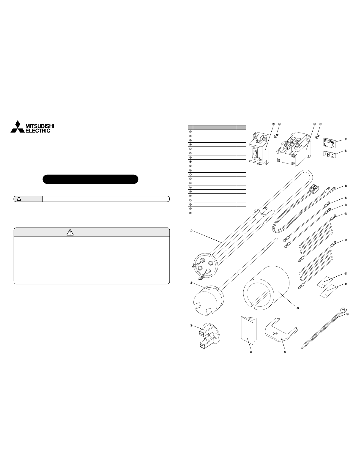
●
Item
Immersion heater
Thermostat (High limit thermal cut-out)
Tab cover
Earth leakage breaker
Screw (4×25)
Relay
Screw (4×16)
Label (for Earth leakage breaker)
Label (for Relay)
Lead wire with connector
Lead wire (Red, 100mm)
Lead wire (Blue, 100mm)
Lead wire (Red, 1500mm)
Lead wire (Blue, 1500mm)
Water-proof cover
Water-proof seal (3x35x25)
Water-proof seal (3x40x25)
Band
Tool
Installation manual
Piece
1
1
1
1
2
1
2
1
1
1
1
1
1
1
1
1
1
1
1
1
Contents
BH79D212H02
10
A1 A2
9
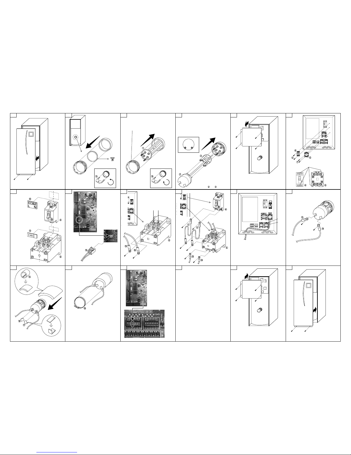
Carefully remove front panel
by disconnecting the control
cable from beneath the unit’s
main control box.
1
The blanking plate and gasket
can be removed using a narrow
flat bladed screwdriver.
Dispose
Check before starting installation
that no water is in the tank.
2
Diagonally locate the thermostat pockets on upper
right and bottom left with termini on the upper left
and bottom right sides as shown.
Secure tightly with the nut to prevent water leakage.
(Recommended torque = 10 N•m)
3
Reinstate plastic tab cover over
the connectors then insert the
thermostat rod into the upper
right hand pocket.
The terminals on the white
plastic head should be positioned
at the bottom as shown.
4
Assemble and securely.
5
Screw positions
6
Place the terminal
blocks so that the
orientations of the
labels are correct.
7
Align the centre lines
and as shown.
Align the centre
lines and
as shown.
Connector CNIH
8 11
Do not insert the lead wires and into the
opening that the main controller wires or the
wireless receiver wires use.
12
13
Run the lead wire through
the slit on the water-proof
cover provided and seal
each terminal screw.
14
Place the band on the joint surface of the
DHW tank.
Secure the water-proof cover around the
cylinder boss using the band provided.
15
Dip Switch
1-4 OFF→ON
(without immersion heater
→with immersion heater)
17 18
Carefully reinstate control cable
connection before reinstating
and securing the front panel.
16
For details about wiring to power supply and
circuit breaker, refer to the installation
manual for the cylinder unit.
Fill tank with water and ensure that no water
leaks around the periphery of the immersion
heater.
BH79D212H02
 Loading...