

Page 1

FLOW TEMP. CONTROLLER 2
(Cased)
PAC-IF031B-E
INSTALLATION MANUAL
For safe and correct use, read this manual thoroughly before installing the FTC2 unit.
OPERATION MANUAL
For safe and correct use, please read this operation manual thoroughly before operating the air-conditioner unit.
FOR INSTALLER
FOR USER
English
Page 2

Contents
1. Safety precautions .....................................................................................2
2. Installing the FTC2 unit .............................................................................3
3. System ......................................................................................................4
4. Electrical work ...........................................................................................7
5. Switch setting of FTC2 ............................................................................ 12
6. Operation setting .....................................................................................14
7. Before test run .........................................................................................21
8. Remote controller operation ....................................................................22
9. Initial setting by remote controller ............................................................ 31
10. Defi nition of analog signal by remote controller ......................................33
11. Troubleshooting ......................................................................................34
Local application factors ................................................................................35
“FTC2” is the abbreviation of “Flow Temperature Controller 2”, which is described as “FTC2” in this manual.
1. Safety precautions
Before installing the FTC2 unit, make sure you read all the “Safety precautions”.
Please report to your supply authority or obtain their consent before
connecting this equipment to the power supply system.
Warning:
Precautions that must be observed to prevent injuries or death.
Caution:
Precautions that must be observed to prevent damages to the unit.
Warning:
• The unit must not be installed by the user. Ask an installer or an authorized
technician to install the unit. If the unit is installed improperly, electric
shock, or fi re may be caused.
• For installation work, follow the instructions in the Installation Manual and
use tools and pipe components specifi cally made for use with refrigerant
specifi ed in the outdoor unit installation manual.
• The unit must be installed according to the instructions in order to minimize the risk of damages by earthquakes, typhoons, or strong winds.
Improperly installed unit may fall down and cause damages or injuries.
The unit must be securely installed on a structure that can sustain its weight.
•
If the unit is mounted on an unstable structure, it may fall down and cause
damages or injuries.
• All electric work must be performed by a qualifi ed technician according to
local regulations and the instructions given in this manual. The unit must
be powered by dedicated power lines and the correct voltage and circuit
breakers must be used. Power lines with insuffi cient capacity or incorrect
electrical work may result in electric shock or fi re.
After installation, perform the test run to ensure normal operation. Then explain
your customer the “Safety Precautions,” use, and maintenance of the unit based on
the information in the Operation Manual provided by local application manufacture.
Both the Installation Manual and the Operation Manual must be given to the user.
These manuals must always be kept by the actual users.
: Indicates a part which must be grounded.
Warning:
Carefully read the labels attached to the unit.
• Only the specified cables can be used for wiring. Connections must be
made securely without tension on the terminals. If cables are connected or
installed improperly, It may result in overheating or fi re.
• Terminal block cover panel of the unit must be fi rmly fi xed. If the cover
panel is mounted improperly, dust and moisture may enter the unit, and it
may cause electric shock or fi re.
• Make sure to use accessories authorized by Mitsubishi Electric and ask
an installer or an authorized technician to install them. If accessories are
improperly installed, it may cause electric shock, or fi re.
• Do not remodel the unit. Consult an installer for repairs. If alterations or
repairs are not performed correctly, it may cause electric shock or fi re.
• The user should never attempt to repair the unit or transfer it to another
location. If the unit is installed improperly, it may cause electric shock or
fi re. If the FTC2 unit needs to be repaired or moved, ask an installer or an
authorized technician.
1.1. Before installation (Environment)
Caution:
• Do not install the FTC2 unit in outdoor location as it is designed for indoor
installation only. Otherwise electric shock or breakdown may be caused by
water drop, wind or dust.
Do not use the unit in an unusual environment. If the FTC2 unit is installed or
•
exposed to steam, volatile oil (including machine oil), or sulfuric gas, or exposed to briny air, the internal parts can be damaged.
• Do not install the unit where combustible gases may leak, be produced,
fl ow, or accumulate. If combustible gas accumulates around the unit, it may
cause fi re or explosion.
1.2. Before installation or relocation
Caution:
• Be fully careful when moving the units. Do not hold the packaging bands.
Wear protective gloves to unpack and to move it, in order to avoid your
hands be injured by parts.
1.3. Before electric work
Caution:
• Be sure to install a circuit breaker. If it is not installed, there may be a risk
to get an electric shock.
• For the power lines, use standard cables of suffi cient capacity. Otherwise,
it may cause a short circuit, overheating, or fi re.
• When installing the power lines, do not apply tension to the cables. The
cables may be cut or overheated resulting in a fi re.
1.4. Before starting the test run
Caution:
• Turn on the main power switch of the outdoor unit more than 12 hours
before starting operation. Starting operation immediately after turning on
the power switch can severely damage the internal parts. Keep the main
power switch turned on during the operation period.
• When installing the unit in a hospital or in a building where communications equipment are installed, you may need to take measure to noise and
electronic interference. Inverters, home appliances, high-frequency medical
equipment, and radio communications equipment can cause the FTC2 unit
to malfunction or to breakdown. At the same time, the noise and electric interference from the FTC2 unit may disturb the proper operation of medical
equipment, and communications equipment.
• Be sure to safely dispose of the packaging materials. Packaging materials,
such as nails and other metal or wooden parts may cause injuries.
• Do not wash the FTC2 unit. You may receive an electric shock.
• Make sure to ground the unit. Do not connect the ground wire to gas or
water pipes, lightning rods, or telephone grounding lines. If the unit is not
properly grounded, there may be a risk to get an electric shock.
• Make sure to use circuit breakers (ground fault interrupter, isolating switch
(+B fuse), and molded case circuit breaker) with the specifi ed capacity. If
the circuit breaker capacity is larger than the specified capacity, breakdown or fi re may result.
• Before starting operation, check that all protective parts are correctly in-
stalled. Make sure not to get injured by touching high voltage parts.
• Do not touch any switch with wet hands. There may be a risk to get an
electric shock.
• After stopping operation, make sure to wait at least 5 minutes before turn-
ing off the main power. Otherwise, it may cause breakdown.
1.5. Electric booster and Immersion heaters
Warning:
• FTC2 has signal outputs for booster heaters however it can not isolate
power to them in the event of overheating. All electrical heaters used on
the water circuit must have
2
a) Self cut-out mechanism to prevent overheating OR
b) A thermostat to prevent overheating
Page 3
2. Installing the FTC2 unit
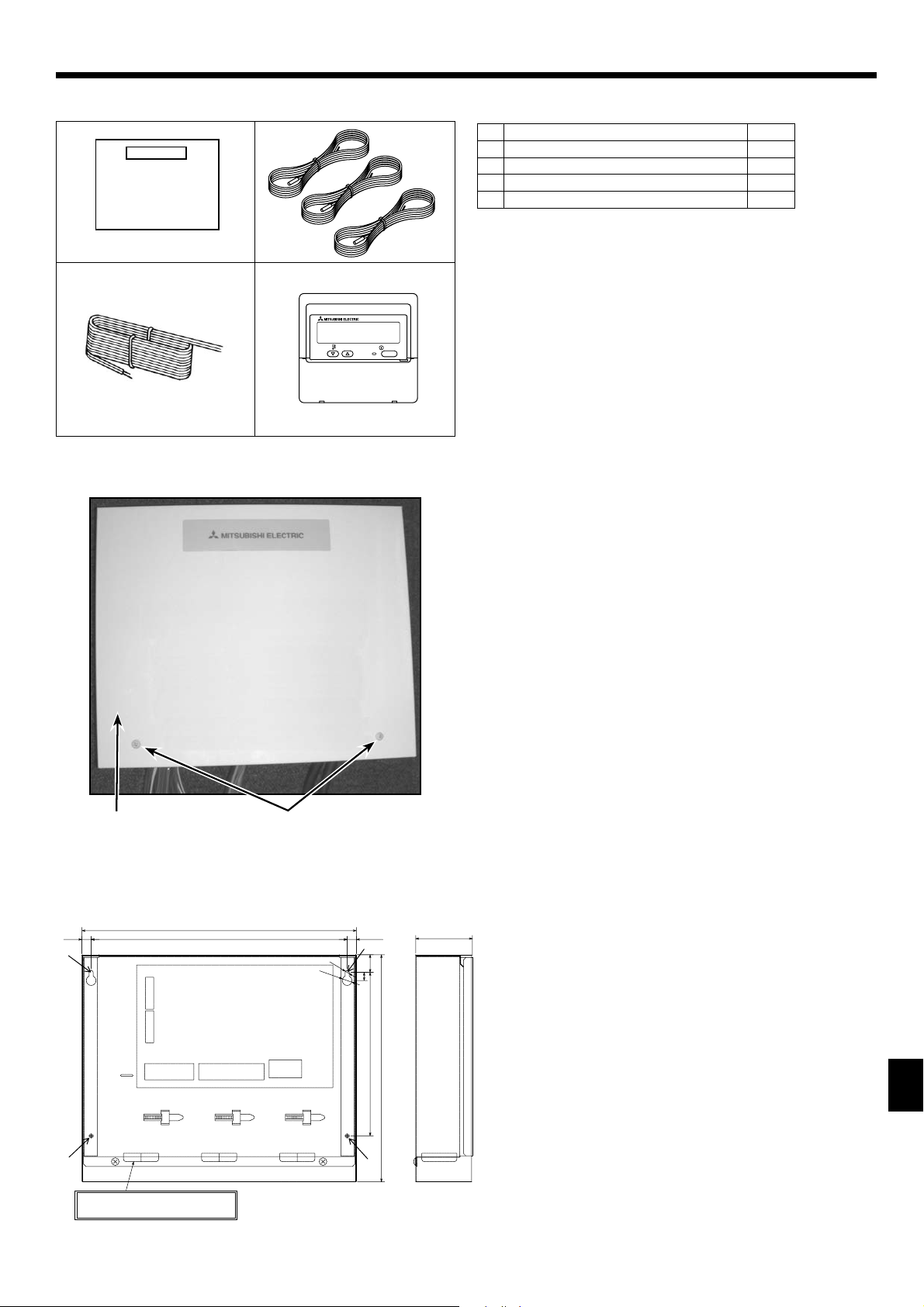
2.1. Check the parts (Fig. 2-1)
The FTC2 unit should be supplied with the following parts.
Part Name Q'ty
FTC2 unit 1
1
Thermistor 3
2
Remote controller cable (5m) 1
3
Remote controller 1
4
TEMP.
Fig. 2-1
ON/OFF
2.2. Choosing the FTC2 unit installation location
• Do not install the FTC2 unit in outdoor location as it is designed for
indoor installation only. (The FTC2 circuit board and casing are not
waterproof.)
• Avoid locations where the unit is exposed to direct sunlight or other
sources of heat.
• Select a location where easy wiring access to the power source is
available.
• Avoid locations where combustible gases may leak, be produced,
fl ow, or accumulate.
• Select a level location that can bear the weight and vibration of the
unit.
• Avoid locations where the unit is exposed to oil, steam, or sulfuric gas.
• Do not install in location that is hot or humid for long periods of time.
2.3. Installing the FTC2 unit (Fig. 2-2, Photo. 2-1)
1. Remove 2 screws from FTC2 unit and remove the cover.
2. Install the 4 screws (locally supplied) in 4 holes.
Screw B Cover
A
Hole for installation
C
BA
11. 5
TB61 TB62
3-ELECTRIC WIRE INLET
When installed on a wall: Lower side
Photo. 2-1
336
313
TB141TB142
Fig. 2-2
TB6
Unit:mm
(11.5)
:5
:12
22
10
200
278
69
3
Page 4
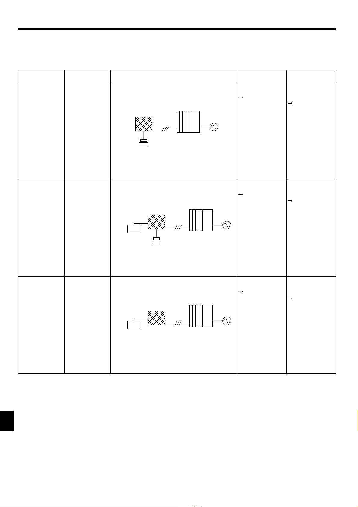
3. System
The FTC2 is designed for use with a number of heat pump systems. Please refer to the following table to fi nd the relevant installation information
for your system.
First step (Electrical work)
Power supplies (Outdoor only)
Remote controller or external input
Mode select
Temp. setting
(PAR-W21MAA) (PAR-W21MAA)
System diagram
FTC2
Remote controller
(PAR-W21MAA)
Outdoor unit
Power supplies
Outdoor unit onlyRemote controllerRemote controller
4.1
4.1.1
Operation mode
input
Remote controller
only
4.2
(External input) (PAR-W21MAA)
(External input)
FTC2
Local controller
(ON/OFF,MODE)
FTC2
Local controller
(ON/OFF,MODE,Temp.)
Remote controller
(PAR-W21MAA)
Outdoor unit
Outdoor unit
Outdoor unit onlyRemote controllerLocal controller
4.1
4.1.1
Outdoor unit onlyAnalog inputLocal controller
4.1
4.1.1
Remote controller
and external input
4.2
4.3
4.3.1
External input and
analog input
4.3
4.3.1
4.3.2
4
Page 5
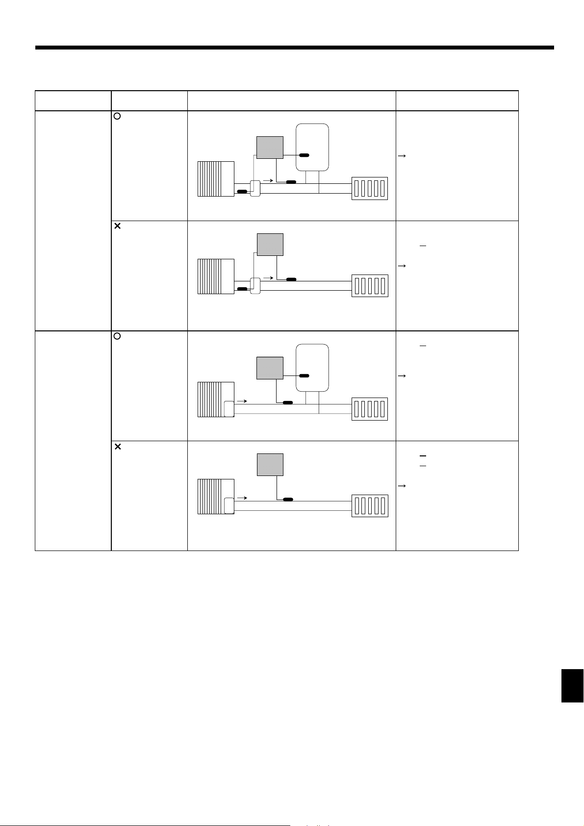
3. System
Second step (thermistor setting)
Outdoor type (SPLIT type / PACKAGED type)
Domestic Hot Water (DHW) tank
Outdoor unit type DHW tank System diagram
SPLIT type
(Present)
Outdoor unit
TH2
Heat exchanger
FTC2
TH1
DHW tank
TH5
Thermistor
(TH1,TH2,TH5)
TH1: actual flow water temp.
TH2: refrigerant pipe temp.
TH5: actual DHW tank temp.
4.4
Radiator etc.
PACKAGED type
(Absent)
(Present)
(Absent)
Outdoo r uni t
Outdoor unit
Heat e xchanger
Outdoo r unit
FTC2
TH2
Heat exchanger
FTC2
FTC2
TH1
TH1
TH1
DHW tank
TH5
Radiator etc.
Radiator etc.
Radiator etc.
TH1: actual flow water temp.
TH2: refrigerant pipe temp.
TH5:
4.4
TH1: actual flow water temp.
TH2:
TH5: actual DHW tank temp.
4.4
TH1: actual flow water temp.
TH2:
TH5:
4.4
Heat exchanger
5
Page 6
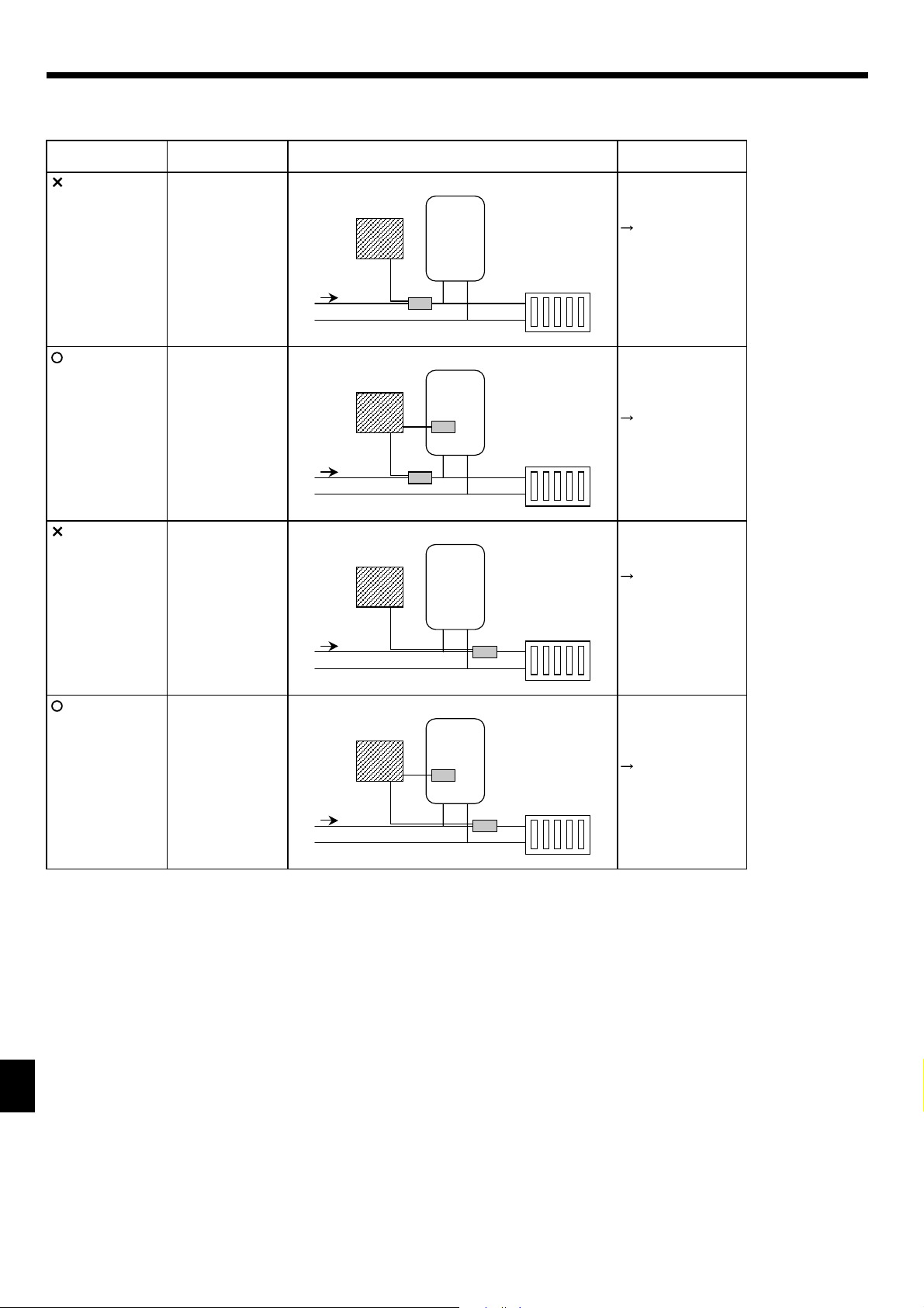
3. System
Third step (Heater setting)
Immersion heater
Booster heater position
Immersion heater
(Absent)
Booster heater
position
both DHW
and Heating
System diagram
FTC2
Sanitary tank
Output signal
Booster heater
only
4.5
(Present)
(Absent)
(Present)
both DHW
and Heating
Heating only
Heating only
Booster
heater
FTC2
Booster
heater
FTC2
Booster
heater
FTC2
Sanitary tank
Immersion
heater
Sanitary tank
Sanitary tank
Immersion
heater
Radiator etc.
Booster heater
and
Immersion heater
4.5
Radiator etc.
Booster heater
only
4.5
Radiator etc.
Booster heater
and
Immersion heater
4.5
Booster
heater
Radiator etc.
6
Page 7
4. Electrical work
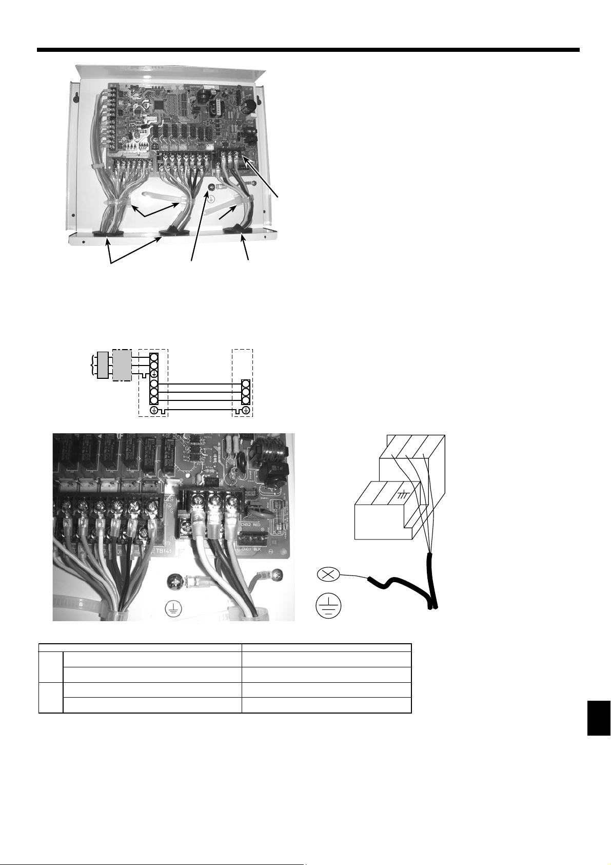
4.1. FTC2 (Photo. 4-1)
1. Remove the cover.
2. Wire the power cable and control cable separately through the
respective wiring inlets given in the photo.
• Make sure to put screws tightly.
Inlet for control cable
A
Inlet for power cable
B
Clamp
C
FTC2 / Outdoor unit connecting terminals
D
Earth terminal
E
D
C
C
Photo. 4-1
A
E
4.1.1. FTC2 unit power supplied from outdoor unit
The outdoor unit must be powered properly. (Details are shown in its installation manual.)
D
L
AB C
N
S1
S2
S3
E
B
F
S1
S2
S3
A Outdoor unit power supply
B Earth leakage breaker
C Wiring circuit breaker or isolating switch
D Outdoor unit
E FTC2 unit/outdoor unit connecting cables
F FTC2 unit
TB6
S2 S3S1
NL
E: FTC2 unit/outdoor unit
connecting cables
Earth cable
Photo. 4-2
FTC2 unit model
FTC2 unit-Outdoor unit
)
2
(mm
Wiring
FTC2 unit-Outdoor unit earth
Wire No. × size
FTC2 unit-Outdoor unit S1-S2
rating
Circuit
FTC2 unit-Outdoor unit S2-S3
*1. Max. 80 m
*2. The fi gures are NOT always against the ground.
S3 terminal has DC 24 V against S2 terminal. However between S3 and S1, these terminals are not electrically insulated by the transformer or other device.
*1
*1
*2
*2
Notes: 1. Wiring size must comply with the applicable local and national codes.
2. Power supply cables and FTC2 unit/outdoor unit connecting cables shall not be lighter than polychloroprene sheathed fl exible
cable. (Design 60245 IEC 57)
3. Install an earth wire longer than other cables.
PAC-IF031B-E
3 × 1.5 (polar)
1× Min.1.5
AC 230 V
DC24 V
7
Page 8

4. Electrical work
30120
46
83.5
Fig. 4-1
B-1. B-2.
TB61
4.2. Connecting the wired remote controller
4.2.1. Connecting the wired remote controller cable to FTC2
Connect the wired remote controller cable to 5 and 6 on the terminal
block (TB62) on the FTC2 controller. (Photo. 4-3)
3030
Wiring wire No. × size (mm
The 5m wire is attached as an accessory. Max. 500 m
Wiring size must comply with the applicable local and national codes.
Circuit rating: DC12V
Circuit rating is NOT always against the ground.
4.2.2. For wired remote controller
1) Installing procedures
(1) Select an installing position for the remote controller. (Fig. 4-1)
► Procure the following parts locally:
2 piece switch box
Thin copper conduit tube
Lock nuts and bushings
[Fig. 4-1]
Remote controller profi le
A
Required clearances surrounding the remote controller
B
Installation pitch
C
(2) Seal the service entrance for the remote controller cable with putty
to prevent possible invasion of dew drops, water, cockroaches or insects. (Fig. 4-2)
Fig. 4-2
For installation in the switch box
A
For direct installation on the wall, select one of the followings:
B
• Prepare a hole through the wall to pass the remote controller cable (in
order to take out the remote controller cable from the back), then seal
the hole with putty.
• Take out the remote controller cable through the cut-out upper case,
then seal the cut-out notch with putty.
BTB
A6
Fig. 4-3
B-1. To lead the remote controller cable from the back of the con-
troller
B-2. To take out the remote controller cable through the upper por-
tion
[Fig. 4-2]
Wall
C
Conduit
D
Lock nut
E
Bushing
F
2) Connecting procedures (Fig. 4-3)
Connect the remote controller cable to the terminal block.
1
To TB62 No.5 and 6 on the FTC2 unit
A
TB6 (No polarity)
B
2
) : 2×0.3 (Non-polar)
Switch box
G
Remote controller cable
H
Seal with putty
I
Wood screw
J
TH1
TH2
TH5
TB62
Wired remote controller cable
Photo.4-3
8
Page 9
4. Electrical work
4.3. Connecting external input
FTC2 can be operated by following external input.
4.3.1. EXTERNAL INPUT ( Contact signal )
Terminal block OFF (Open) ON (Short) Remark
TB142 1-2 (IN1) OFF Emergency
TB142 3-4 (IN2) OFF
TB142 5-6 (IN3) Normal Comp. OFF SW3-6 = OFF
Comp. OFF Normal SW3-6 = ON
TB142 7-8 (IN4) OFF Cooling
TB142 10-11 (COM-IN5) OFF Heating
TB142 10-12 (COM-IN6) OFF Heating ECO *1
TB142 10-13 (COM-IN7) OFF Hot Water *4
TB142 10-14 (COM-IN8) OFF Anti-Freeze
TB62 1-2 (Ana. IN1) Normal operation Comp. OFF *2 SW3-4 = OFF
Comp. OFF *2 Normal operation SW3-4 = ON
*1 Heating ECO mode sets the set temperature depending on the outdoor temperature.
*2 In case of Cooling, Heating, Heating ECO and Anti-Freeze.
*3 Input signal: Pulse
Pulse specifi cations: ON (short)
OFF (open)
*4 When SW1-1 and SW1-2 are OFF, the mode is switched into Auto hot water.
Input signal: Pulse
Pulse specifi cations: ON (short)
OFF (open)
When SW1-1 or SW1-2, or both are ON, the mode is switched into Hot water.
Legionella prevention *3
200ms or more
200ms or more
TB142
3 5 7 9 11 131
Emergency
Legionella prevention
Forced Comp. OFF →
Cooling
Heating →
HeatingECO →
Hot Water →
Anti-Freeze →
4268101214
At site
→
→
→
FTC2
1
2
3
4
5
6
7
8
9
10
11
12
13
14
TB142
4.3.2. EXTERNAL INPUT ( analog signal ) 4-20mA / 1-5V / 0-10V
Connect the transmission cables to No. 3 and 4 on the terminal block (TB62).
No. 3 on the terminal block (TB62) : Plus side
No. 4 on the terminal block (TB62) : Minus side (Reference side)
Thermostat
4-20mA/1-5V/0-10V
Wired remote controller
FTC2At site
1
(
2
3
4
5
6
TB62
+
(
(
4-20mA / 1-5V / 0-10V setting
FLOW TEMP.
No.2 Temp.
No.1 Temp.
Stop
4-20mA
1-5V
0-10V
Refer to the section 10 for details about No1, 2 Temp.
0mA -- 4mA --------------- 20mA
0V-------1V------------------- 5V
0V------------------10V
ANALOG
SIGNAL
TB141
Photo.4-4
Caution:
The external input signals are separated by basic insulation from power supply for the unit.
The external input signals should be separated by supplementary insulation from where user may touch in case that it is installed where
user may touch.
Connect the terminals by using the ring terminals and also insulate the cables of adjoining terminals when wiring to terminal block.
4.3.3. Wiring specifi cation of External input
Locally supplied parts
Item Name Model and specifi cations
External input
function
External input signal
wire
Use sheathed vinyl coated cord or cable.
Max. 10m
Wire type :CV, CVS or equivalent
Wire size : Stranded wire 0.5mm
Solid wire : {0.65mm to {1.2mm
Switch Non-voltage "a" contact signals
Remote switch : minimum applicable load DC 12V, 1mA
2
to 1.25mm
2
9
Page 10
4. Electrical work
4.4. Connecting thermistor cable
Connect the thermistor 2 for the FTC2 controller.
4.4.1. Connecting the actual fl ow water temp. thermistor (TH1)
Connect the thermistor for the actual fl ow water temp. to 1 and 2 on the
terminal block (TB61) on the FTC2 controller.
When the thermistor cables are too long, cut them at the appropriate
length.
Do not bind them in the FTC2 unit.
<Thermistor position>
Put TH1 on
water piping (water outlet side) after booster heater.
Note: Be sure to attach the TH1 where it detects Flow temp.(Water
oulet side) correctly.
4.4.2. Connecting the pipe temp. thermistor (TH2)
Connect the thermistor for the refrigerant pipe temp. to 3 and 4 on the
terminal block (TB61) on the FTC2 controller.
For packaged Outdoor unit : It is NOT necessary to connect TH2.
For split Outdoor unit : Connect TH2.
When the thermistor cables supplied with FTC2 are too long, cut them to
the appropriate length.
Do not bind them in the FTC2 unit.
<Thermistor position>
Put the TH2 on refrigerant piping (Liquid side).
It is better to protect the thermistor with heat insulating materials not to be affected by the ambient temperature.
Note: Be sure to attach the TH2 where it detects Refrigerant piping temp. (Liquid side) correctly.
TB61
TH1
TH2
TH5
Photo.4-3
TB62
Wired remote controller cable
4.4.3. Connecting the actual DHW tank thermistor (TH5)
Connect the thermistor for the actual DHW tank temp. to 5 and 6 on the terminal block (TB61) on the FTC2 controller.
When the thermistor cables supplied with the FTC2 are too long, cut them to the appropriate length.
Do not bind them in the FTC2 unit.
<Thermistor position>
Put the TH5 on the DHW tank. It should be positioned directly onto the lower half of the external surface of the tank.
Caution:
Do not route the thermistor cables together with power cables.
The sensor part of the thermistor should be installed where user must not touch.
(It is separated by the supplementary insulation from where user may touch.)
4.4.4. Thermistor position and necessity
For packaged type Outdoor unit: It is NOT necessary to connect TH2.
For split type Outdoor unit: Connect TH2
<Thermistor position and necessity>
Outdoor Type DHW tank TH1 TH2 TH5
PACKAGED type
SPLIT type
Present ΟХΟ
Absent ΟХХ
Present O O O
Absent ΟΟХ
Ο: Necessary. Connect the thermistor.
Х: Not necessary. The thermistor is not required, do not connect.
SPLIT type outdoor unit with DHW tank
Refrigerant LIQUID side
Outdoor unit
TH2
SPLIT type
(without a refrigerant-water HEX inside)
Refrigerant piping
FTC2
*1
*1 Refrigerant-water HEX
Water OUTLET
Booster heater
Water piping
TH1
side
DHW tank
temperature
TH5
PACKAGED type outdoor unit with DHW tank
Water OUTLET side
after Booster heater
Outdoor unit
*1
PACKAGED type
(with a refrigerant-water HEX inside)
TH1
Booster heater
Water piping
TH2:
not necessary
*1 Refrigerant-water HEX
FTC2
DHW tank
temperature
TH2
TH5
SPLIT type outdoor unit without DHW tank
Refrigerant LIQUID side
Outdoor unit
TH2
Refrigerant piping
SPLIT type
(without a refrigerant-water HEX inside)
FTC2
*1
*1 Refrigerant-water HEX
10
Water OUTLET
Booster heater
Water piping
TH1
side
TH5:
not necessary
TH5
PACKAGED type outdoor unit without DHW tank
Water OUTLET side
after Booster heater
Outdoor unit
*1
PACKAGED type
(with a refrigerant-water HEX inside)
TH1
Booster heater
Water piping
FTC2
TH2:
not necessary
TH2 TH5
*1 Refrigerant-water HEX
TH5:
not necessary
Page 11
4. Electrical work
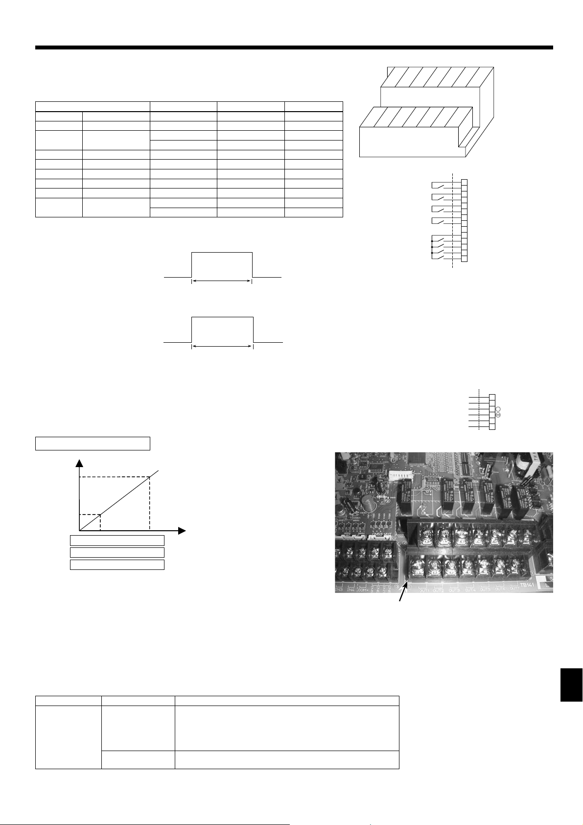
4.5. Connecting external output signal
All outputs has AC 230V signal
Output Use Signal Max. current
OUT1 Water circulation pump AC 230A signal for relay drive 0.5 A
OUT2 Booster heater 1 AC 230A signal for relay drive 0.5 A
OUT3 Booster heater 2 AC 230A signal for relay drive 0.5 A
OUT4 Immersion heater AC 230A signal for relay drive 0.5 A
OUT5 3-port valve AC 230A signal for relay drive 0.5 A
OUT6 Defrost AC 230A signal for direct use 0.5 A
OUT7 Error output AC 230A signal for direct use 0.5 A
*FTC2 has terminal beds for AC 230V output signal. (Relays are NOT available on FTC2)
Caution :
Do not drive directly the pump, heater and valve by these output signals.
Connect the surge absorber according to the load at site.
Wiring specifi cation of External output
Locally supplied parts
Item Name Model and specifi cations
External output
function
External output signal
wire
Relay, etc. AC 230V signal 0.5 A or less
Use sheathed vinyl coated cord or cable.
Max. 50m
Wire type : CV, CVS or equivalent
Wire size : Stranded wire 0.5mm² to 1.25mm²
Solid wire: {0.65mm to {1.2mm
*Connect the surge absorber according to the load at site.
TB141
42
6 8 10 12 14
357911131
11
Page 12

5. Switch setting of FTC2
The functionality of the heat pump is determined by the setting of the Dip switches from SW1 to SW3, and SW6 found on the
FTC2 controller. (Photo. 5-1)
SW1
SW2
SW3
SW6
Photo. 5-1
5.1 Operation mode input method
Input method can be selected with Dip SW 1-1 / 1-2
ON/OFF Input Change mode Input Change TEMP. Input SW1-1 SW1-2 SW6-1 SW6-2
Wired remote controller
(PAR-W21MAA)
External input
(non-voltage contact)
Analog input (1-5V) *1
Analog input (4-20mA) *2
External input
(non-voltage contact)
*1. 4-20mA OFF: 0 ~ 2mA
*2. 1-5V
OFF: 0 ~ 0.5V
Wired remote controller
(PAR-W21MAA)
or External input
External input
(non-voltage contact)
External input
(non-voltage contact)
External input
(non-voltage contact)
External input
(non-voltage contact)
Flow
switch
TH1
TH2
TH5
Wired remote controller
(PAR-W21MAA)
Wired remote controller
(PAR-W21MAA)
Analog input (1-5V) OFF
Analog input (4-20mA) OFF
Analog input (0-10V)
OFF OFF OFF OFF
OFF OFF OFF
ON
ON
ON ON ON
ON ON
Local system controller
External input
IN1 IN2 IN3 IN4 IN5 IN6 IN7 IN8
Emergency
TH1
TH2
TH5
OUT1 OUT2 OUT3 OUT4 OUT5 OUT6 OUT7
Legionella
prevention
Comp
OFF
Heating Hot
Cooling
FTC2
Heating
ECO
Water
OFF
OFF OFF
Anti
freeze
Ana.IN1
ON
Analog input
Non-voltage
contact
Thermostat
Water
circulation
pump
Booster
heater 1
Booster
heater 2
5.2. Thermistor setting
Set Dip SW 1-3 according to whether the system has a DHW tank.
SW 1-3 Setting Notes
OFF With DHW tank Necessary to connect TH5
ON Without DHW tank NOT necessary to connect TH5
When Dip SW 1-3 is ON, DHW mode is NOT available.
Set Dip SW 1-6 according to the connected Heat pump unit type.
SW 1-6 Setting Notes
OFF SPLIT type Necessary to connect TH2
ON PACKAGED type NOT necessary to connect TH2
12
Immersion
heater
3-port
valve
Defrost
Error
PAR-W21MAA
Page 13

5. Switch setting of FTC2
5.3. Heater setting
Set Dip SW 1-4 according to whether the system has an Immersion heater.
SW 1-4 Setting
OFF Without Immersion heater
ON With Immersion heater
Set Dip SW 1-5 according to the location of Booster heater.
SW 1-5 Setting
OFF For both Domestic Hot Water (DHW) and Heating
ON For Heating only or without Booster heater
< Summary: Heater setting >
SW 1-4
Immersion heater
OFF
(Without Immersion heater)
ON
(With Immersion heater)
SW 1-5
Booster heater position
OFF
(For both DHW and Heating)
OFF
(For both DHW and Heating)
Figure
Booster heater
TH1
Booster heater
Sanitary tank
TH5
TH1
Sanitary tank
TH5
Radiator
Immersion heater
Radiator
OFF
(Without Immersion heater)
ON
(With Immersion heater)
ON
(For Heating only)
ON
(For Heating only)
5.4. Other setting
Set Dip SW 1-7 according to the Cooling mode usage.
SW 1-7 Setting
OFF Not in use (Operation mode: Heating/Heating ECO/Hot Water/Anti-freeze)
ON
When Dip SW 1-7 is OFF, Cooling mode is NOT available.
Dip SW 3-4: External input (Ana. IN1) logic change
Exteranl input (Ana. IN1) is for the connection of thermostat.
SW 3-4 Ana. IN1 (TB62 No.1, 2) input Item
OFF
ON
*1 In case of Cooling, Heating, Heating Eco, Anti-freeze.
In use (Operation mode: Heating/Heating ECO/Hot Water/Anti-freeze/Cooling)
OFF (open) Normal operation
ON (short) Heat pump unit OFF *1
OFF (open) Heat pump unit OFF *1
ON (short) Normal operation
TH5
TH5
Sanitary tank
Booster heater
Sanitary tank
Booster heater
Radiator
TH1
Immersion heater
Radiator
TH1
Dip SW 3-6: External input (IN1) logic change
SW 3-6 IN1 (TB142 No.5, 6) input Item
OFF
ON
OFF (open) Normal operation
ON (short) Heat pump unit OFF
OFF (open) Heat pump unit OFF
ON (short) Normal operation
Dip SW 3-5, 3-8: Not in use. Set to OFF. (Initial setting)
13
Page 14

6. Operation setting
6.1. Automatic change over mode
When a system includes a Domestic Hot Water (DHW) tank and a space heating requirement Automatic change over mode should be selected.
Selection is made with Dip SW1-8.
If the system does NOT include a DHW tank Dip SW 1-3 is ON and Automatic change over mode is invalid.
SW 1-8 Operation
OFF With Automatic change over mode (the system has a DHW tank).
ON
Without
OR
Operations on each mode with Automatic change over mode.
<SW1-1 OFF / SW1-2 OFF>
Mode System operation
Heating Heating and DHW (Automatic change over mode)
Heating ECO Heating with Weather compensation and DHW (Automatic change over mode)
Hot Water Domestic Hot Water only
Anti-freeze Prevents pipe work freezing during periods of inactivity
<SW1-1 ON / SW1-2 OFF or SW1-1 OFF / SW1-2 ON or SW1-1 ON / SW1-2 ON>
Mode System operation
Heating Heating only *
Heating ECO Heating only with Weather compensation *
Hot Water Domestic Hot Water only *
Anti-freeze Prevents pipe work freezing during periods of inactivity
*1 Automatic change over mode is available only when SW1-1/1-2 is set ON/OFF and the FTC2 receives
external signals for Heating (or Heating ECO) and DHW at the same time from the local controller.
Automatic change over mode is NOT available when SW1-1/1-2 are set OFF/ON or ON/ON.
Automatic change over mode (the system does NOT have a DHW tank).
The end user would like to control the switch over between DHW and space heating.
1
1
1
Operations on each mode without Automatic change over mode.
Mode System operation
Heating Heating only
Heating ECO Heating only with Weather compensation
Hot Water Domestic Hot Water only
Anti-freeze Prevents pipe work freezing during periods of inactivity
When automatic change over mode is selected DHW always has priority over space heating.
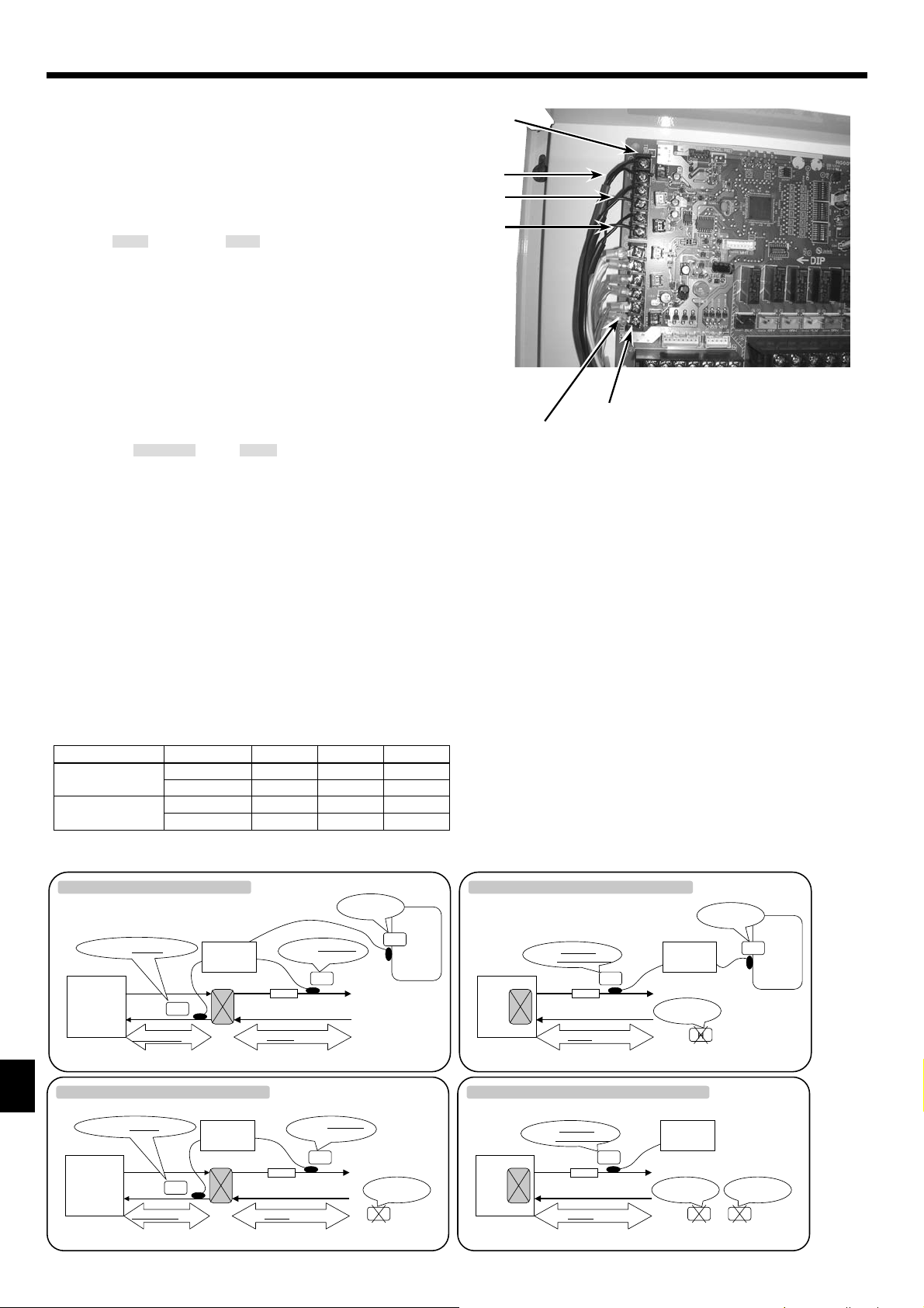
System examples
Example 1:
Only our Remote controller (PAR-W21MAA) is used for system control.
NO local system controller exists.
Target temperature for each mode and Heating or Heating ECO mode are set
with PAR-W21MAA. Automatic change over mode is selected (SW 1-8 must
be switched to OFF). The system will automatically change from Heating or
Heating ECO to DHW mode and back dependent on the DHW tank temperature (TH5).
Example 2:
A local timer and our Remote controller (PAR-W21MAA) are used
for system control.
Target temperature for each mode and Heating or Heating ECO mode are set
with PAR-W21MAA.
A local timer is used rather than automatic change over mode (SW1-8 must
be switched to ON). The system runs in Heating or Heating ECO until a signal
is received from the local timer (the signal received from local timer must
be longer than 200 ms). The system then switches to DHW mode.
Once DHW mode is satisfied the system automatically reverts to Heating or
Heating ECO.
SW 1-1 OFF / SW 1-2 OFF / SW 1-8 OFF
Flow
switch
TH1
TH2
TH5
SW 1-1 OFF / SW 1-2 OFF / SW 1-8 ON
Flow
switch
TH1
TH2
TH5
IN1 IN2 IN 3 IN4 IN5 IN6 IN7 IN8
Emergency
TH1
TH2
TH5
OUT1 OUT2 OUT3 OUT4 OUT5 OUT6 OUT7
Water
circulation
pump
Legionella
prevention
Booster
heater 1
Comp
OFF
Booster
heater 2
Heating Hot
Cooling
FTC2
Immersion
heater
Heating
ECO
3-port
valve
Water
Defrost
Local timer
External input
IN1 IN2 IN3 IN4 IN5 IN6 I N7 IN8
Emergency
TH1
TH2
TH5
OUT1 OUT2 OUT3 OUT4 OUT5 OUT6 OUT7
Water
circulation
pump
Legionella
prevention
Booster
heater 1
Comp
OFF
Booster
heater 2
Heating Hot
Cooling
FTC2
Immersion
heater
Heating
ECO
3-port
valve
Water
Defrost
Anti
freeze
Error
Anti
freeze
Error
PAR-W21MAA
PAR-W21MAA
14
Page 15

6. Operation setting
System examples
Example 3:
A Local controller and our Remote controller (PAR-W21MAA) are used
for system control.
Target temperatures for each mode are set with PAR-W21MAA.
A local controller is used to select the running mode rather than Automatic
change over mode (SW 1-8 is switched to ON).
Automatic change over mode is available when SW1-8 is OFF and the FTC2
receives external signals for Heating (or Heating ECO) and DHW at the same
time from the local controller.
<IMPORTANT NOTE>
In this system, the operation mode must be switched by a local controller
which can output separate signals for each operation mode.
(This can be realised by using a schedule timer and relays.)
Example 4:
ONLY a Local controller is used for system control.
The system operates in the same way as Example 3 except that the target
temperatures for each mode must also be inputted via the analogue signal
from the local controller. (SW1-8 must be switched to ON)
<IMPORTANT NOTE>
In this system, the operation mode must be switched by a local controller
which can output separate signals for each operation mode. In addition,
the target temperature in each operation mode must be sent by ANALOG
signal from the local controller.
SW 1-1 ON / SW 1-2 OFF / SW 1-8 ON
or SW 1-1 ON / SW 1-2 OFF / SW 1-8 OFF
Local system controller
Heating Hot
Cooling
FTC2
Immersion
heater
External input
Heating
ECO
3-port
valve
Defrost
Water
Anti
freeze
Error
Error
PAR-W21MAA
Flow
switch
TH1
TH2
TH5
IN1 IN2 IN3 IN4 IN5 IN6 I N7 IN8
Emergency
TH1
TH2
TH5
OUT1 OUT2 OUT3 OU T4 OU T5 OUT6 OUT7
Water
circulation
pump
Legionella
prevention
Booster
heater 1
Comp
OFF
Booster
heater 2
SW 1-1 OFF / SW 1-2 ON / SW 1-8 ON
or SW 1-1 ON / SW 1-2 ON / SW 1-8 ON
Local system controller
Heating Hot
Cooling
FTC2
External input
Heating
ECO
Water
Anti
freeze
Flow
switch
TH1
TH2
TH5
IN1 IN2 IN3 IN4 IN5 IN6 IN7 IN8
Emergency
TH1
TH2
TH5
OUT1 OUT2 OUT3 O UT4 OUT5 OUT6 OUT7
Legionella
prevention
Comp
OFF
Analog input
Water
circulation
pump
Booster
heater 1
Booster
heater 2
Immersion
heater
3-port
valve
Defrost
Error
Error
6.2. DHW OFF conditions
DHW can be selected in 2 ways
Pattern 1.
An external input or remote controller is used to switch to DHW mode.
DHW pattern 1 will turn off when the DHW tank reaches set temperature consecutively for 1 minute.
Then the heat pump will turn OFF
Pattern 2.
Automatic change over mode or an external input (e.g. Local timer – signal received must last > 5secs) is used to switch to DHW mode.
DHW pattern 2 will switch off under the following conditions;
a) The DHW tank reaches set temperature T
b) The system has been in DHW mode consecutively for H
(This allows the system to switch back to Heating or Heating ECO mode should the system fail to reach the set temperature for any reason)
System operation status at start-up H
First power-on
First starting up after Initial filling up
TH5 < 25 deg C (Tank temperature is low.)
Others
* As shown in the table, H
time
becomes longer when the water temperature in the tank is low. This is to delay the operation switchover to Heating mode.
Then the heat pump will revert to Heating or Heating ECO mode.
HW consecutively for 1 minute.
time (minutes)
time (minutes)
300
180
15
Page 16

6. Operation setting
6.3. DHW Heating Procedure
The heating of DHW tank is done in 2 stages, firstly the "Heat pump phase" followed by the "Electric heater phase".
6.3.1. Heat Pump Phase
The Heat pump phase for DHW mode, is used when the temperature difference between tank set temperature and
TH5iseither10degCor20degC(∆T
∆T
H is selected using Dip SW2-1
SW 2-1 Operation
OFF ∆T
ON
H =10degC
∆T
H =20degC
The heat pump will turn off or revert to heating when:
Tank temperature (TH5) > DHW set temperature consecutively for 1 minute.
Heat Pump Operation
The heat pump will be controlled directly by the FTC2 while in DHW mode. The operation characteristics can be selected using Dip SW2-2.
Option 1 – COP priority mode
In this mode the heat pump will heat the water over a slightly longer period of time with a controlled frequency, improving the coefficient of
performance. The result of this will be a more economical DHW heat up.
Option 2 – Speed priority mode
In this mode the heat pump will run at maximum frequency during DHW heat up. The result of this will be a reduced time to heat the tank but also
areductioninCOPandsoanincreaseinenergyconsumption.
SW 2-2 Operation
OFF
ON
COP priority mode
(Operation frequency is controlled to have higher COP.)
Speed priority mode
(Heat pump unit runs at the maximum frequency to reduce operation time.)
There is a 30 sec. delay in the Heat pump unit start to ensure the water circulation pump starts running before the Heat pump unit.
H)
Other factors in the Heat pump phase
Heat pump status
Water circulation
pump status
3-port valve
status
ON for DHW ON ON
OFF for DHW OFF OFF
Booster heater 1
status
Booster heater 2
status
Electric heaters are not used in the Heat pump
phase
Immersion
heater status
6.3.2. Electric Heater Phase
Electric heater phase for DHW, is used when tank temperature (TH5) is less than DHW set temperature and the temperature increase is in
10 minutes is smaller than 1 deg C.
Electric heater phase will switch off when:
Tank temperature TH5 > DHW set temperature consecutively for 1 minute.
Electric Heater Phase Operation
The electric heater phase will vary dependent on the position of the heater within the heating circuit.
Electric heater phase TYPE B
Immersion
ON
heater
TH5
Sanitary tank
Immersion heater
Booster
Booster
heater
heater OFF
Radiator
TH1
Heat
Booster
heater
Electric heater phase TYPE A
Immersion
ON
heater
Sanitary tank
TH5
ON
TH1
Booster
heater
Immersion heater
Radiator
Heat
pump
unit
OFF
pump
unit
ON
Pump
ON
Keep to
DHW circuit
Pump
ON
Switch to
Heating circuit
The Dip switch settings for this operation are given in the following table.
SW 1-4 SW1-5
(Immersion heater) (Booster heater)
OFF
without
(
ON
with
(
IH)
OFF
without
(
ON
(with IH)
IH)
IH)
OFF
(BH for both DHW and Heating)
OFF
(BH for both DHW and Heating)
ON
(BH for Heating only)
ON
(BH for Heating only)
(Immersion heater used)
No heater in DHW circuit No heater in DHW circuit
OFF
TYPE A TYPE A
TYPE A TYPE A
TYPE B No heater in DHW circuit
* BH : Booster heater IH : Immersion heater
16
SW 2-7
ON
(Immersion heater not
used or only for Legionella)
Page 17

6. Operation setting
System Characteristics
System type
A (SW1-5 OFF)
B (SW1-4 ON,
SW1-5 ON,
SW2-7 OFF)
Heat pump
status
ON ON ON ON ON ON
OFF ON OFF OFF OFF
Water circulation
pump status
3-port valve
status
Booster heater
1 status
Booster heater
2 status
Immersion
heater status
ON
Heater operation at Electric heater phase in Domestic Hot Water mode
SW 2-7
SW 1-4 SW1-5
(Immersion heater) (Booster heater)
OFF
without
(
ON
with
(
OFF
without
(
ON
with
(
IH)
IH)
IH)
IH)
OFF
(BH for both DHW and Heating)
OFF
(BH for both DHW and Heating)
ON
(BH for Heating only)
ON
(BH for Heating only)
(Immersion heater used)
OFF
BH1,2 : ON
IH : OFF
ON
BH1,2 :
ON
IH :
(Immersion heater not
used or only for Legionella)
BH1,2 : ON
IH : OFF
BH1,2 :
IH : OFF
No heater in DHW circuit No heater in DHW circuit
BH1,2 : OFF
ON
IH :
No heater in DHW circuit
ON
ON
* BH : Booster heater IH : Immersion heater
6.4. Legionella Prevention mode
It is recommended that sanitary hot water stored in t
In Legionella prevention mode, the system runs to let the temperature in the DHW tank (TH5) reach TLP deg C. The temperature TLP
can be set using Dip SW 2-6.
SW 2-6 Setting temperature
OFF T
ON T
LP=60 deg C
LP=65 deg C
The 65 deg C setting can NOT be selected when the there is no heater in the DHW circuit, Dip SW settings is as follows;
SW 1-4 OFF and SW1-5 ON
anks is heated periodically to 60 deg C or above for the prevention of Legionella.
6.4.1. Start Condition and Finish Conditions
How often the Legionella prevention operation is activated is selected using Dip SW 2-4 and 2-5.
SW 2-4 SW 2-5 Operation
OFF OFF Activate every DHW operation.
ON OFF Activate every "15 times" DHW operations.
OFF ON Activate every "150 times" DHW operations.
ON ON Activate by external input signal (IN2)
Legionella prevention mode is satisfied when TH5> T
LP deg C consecutively for 1 minute
The Legionella prevention mode is satisfied in 2 stages, firstly the heat pump phase followed by the electric heater phase.
Electric heater phase is required if tank temperature (TH5) does not increase for some reason or once TH5 reaches the set temperature T
HW.
Start Electric heater phase conditions:
TH5 temperature increase in 10 minutes < 1degC OR
TH5 > DHW set temperature (T
HW)consecutivelyfor1 minute
Finish Electric heater phase condition:
TH5 > T
LP deg C consecutively for 1 minute
6.5. Heating and Heating ECO mode
Choice of either Heating or Heating ECO mode is made using the PAR-W21MAA or local controller. Both modes use the Heat pump to heat the
water to the set point T
if needed.
There is a 1 minute delay before the Heat pump unit starts, so that the Water circulation pump starts running earlier than the Heat pump.
6.5.1. Water Circulation Pump
In Heating or Heating ECO mode the Water circulation pump can be either on continually or turned off 5 minutes after the Heat pump unit stops
operating at which point it will then cycle ON for 1 minute OFF for 3 minutes repeatedly. The setting is selected using Dip SW2-3
SW 2-3 Operation
OFF Always ON (to prevent water circuit from freezing)
ON
OFF 5 minutes after Heat pump unit stops operation. Then the pump will switch ON
for 1 minute OFF for 3 minutes repeatedly until the heat pump starts again.
HE and then allow for the use of Booster heaters if present on the heating circuit to raise the space heating flow temp (TH1)
6.5.2. Booster Heater
If Booster heater is NOT used in Heating mode, Dip SW2-8 must be switched ON.
SW 2-8 Operation
OFF Booster heater used in Heating mode
ON
Booster heater is NOT used in Heating mode (Booster only used in DHW
mode, Legionella prevention mode and Emergency mode)
17
Page 18

6. Operation setting
6.6. Defrost operation
The heat pump process requires regular defrost cycles. The FTC2 operates as follows when the system receives defrost signal and when it
completes defrosting.
6.6.1. When defrost signal is received
3-port valve
In DHW mode the 3-port valve remains ON.
In heating mode the valve can be OFF enabling the Heat pump unit to defrost while keeping the heat in the heating circuit or switched to ON so
system is defrosted using accumulated heat.
Selection is made using Dip SW3-1
SW 3-1 Operation
OFF Remains OFF (defrost while keeping Heating circuit).
ON
Other factors in the Defrost operation
Heat pump status
Defrost operation
6.6.2. When System completes defrost operation
All water circuit parts return to normal settings except for the Heat pump unit.
Heat Pump unit
If the unit was running in Heating or Heating ECO previous to the defrost cycle the system restricts the maximum frequency for 10 minutes from
completion of defrost. In this time it considers the operation it was previously performing.
* The maximum frequency shall be restricted as follows depending on the temperature drop of outlet water during the defrost operation.
Temperature differential at the
beginning of defrost operation
HE Maximum frequency is NOT restricted.
T
HE -TH1<2degC
T
Switch to ON (switch to DHW circuit to defrost. The system defrosts using
accumulated heat for defrosting).
Water circulation
pump status
ON
Booster heater 1
status
Booster heater 2
status
Electric heaters have the same control in each mode
Operation
- TH1 2 deg C
Maximum frequency is restricted for 10 minutes.
Immersion heater
status
6.7. Cooling mode (not available on some models)
Cooling mode works in a similar manner to Heating mode. The heat pump unit is controlled by the FTC2 and has a 1 minute delay in starting to
allow for the Water circulation pump to start before the Heat pump unit.
The operation of the Water circulation pump is selected using Dip SW 2-3 as before
SW 2-3 Operation
OFF Always ON (to prevent water circuit from freezing)
ON
OFF 5 minutes after Heat pump unit stops operation. Then the pump will switch ON
for 1 minute OFF for 3 minutes repeatedly until the heat pump starts again.
The 3-port valve is always OFF in Cooling mode.
The Booster heaters and the Immersion heater are always OFF in Cooling mode.
6.8. Anti-freeze mode
Anti-freeze mode is selected using the PAR-W21MAA or local controller.
Anti-freeze mode characteristics
Anti-freeze mode
Heat pump
status
ON ON ON
OFF OFF ON OFF NOT USED
Water circulation
pump status
Booster heater 1
status
Booster heaters have same control as in
Heating mode
Booster heater 2
status
Immersion
heater status
NOT USED
18
Page 19

6. Operation setting
6.9. Emergency (electric heater only) mode
Emergency mode is available in case of Heat pump unit's failure. In this mode, only electric heater operates as a heat source. Heat pump unit
operation comes first in any operation mode, except in Emergency mode. In the Emergency mode, the heater is switched ON without operating
Heat pump unit.
IMPORTANT: If there are no electric heaters in the circuit "Emergency mode" can not operate.
Emergency mode can activated when the system has external input (IN1) or if Dip SW 3-7 is manually switched to ON.
SW 3-7 Operation
OFF Normal operation
ON
6.9.1. Start condition
Emergency mode shall start when one of the following conditions is fulfilled.
a) The system has external input (IN1).
b) SW 3-7 is ON
6.9.2. Finish condition
Emergency mode shall finish when all of the following conditions are fulfilled.
a) The system does NOT have external input (IN1).
b) SW 3-7 is OFF
Operation mode is selected by local system controller or remote controller settings.
6.9.3. In Domestic Hot Water mode
Heat pump unit is OFF.
Electric heater phase starts immediately.
When the switch setting is for "No heater in DHW circuit", phase can NOT be switched to Electric heater phase.
(System keeps thermo OFF.)
Emergency (electric heater only) mode
.
6.9.4. In Legionella prevention mode
Heat pump unit is OFF.
Electric heater phase starts immediately.
When the switch setting is for "No heater in DHW circuit", phase can NOT be switched to Electric heater phase.
(System finishes Legionella prevention mode.)
6.9.5. In Heating and Anti-freeze mode
Heat pump
status
OFF
Water circulation
pump status
ON
Booster heater 1 status Booster heater 2 status
ON when Heat pump runs
consecutively for 0minuteAND
T
HE -TH1 1deg C
ON when BH1 is ON
consecutively for 10 minutes AND
T
HE -TH1 1degC
Immersion
heater status
NOT USED
6.9.6. Return to Normal operation
When returning from Emergency (electric heater only) mode to Normal operation mode, stop sending the signal of external input (IN1) and switch off
Dip SW 3-7.
Then turn off the power of the outdoor unit and FTC2, and start up the system again.
19
Page 20

6. Operation setting
6.10. SUMMARY of Dip Switch Functions
Dip switch Function OFF ON
Change mode
Input
Remote controller
or External input
SW1-1
SW1-1 SW1-2 ON/OFF Input
OFF OFF Remote controller
Change TEMP.
Input
Remote controller
System select
SW1-2
SW1
ON OFF External input Remote controller
OFF ON
ON ON External input
Analog input
(4-20mA/1-5V)
External input
SW1-3 Domestic Hot Water tank with DHW tank without DHW tank
SW1-4 Immersion heater without Immersion heater with Immersion heater
SW1-5 Booster heater position For both DHW and Heating
For Heating only or without Booster
heater
SW1-6 Connected Heat pump unit type SPLIT type PACKAGED type
SW1-7 Cooling mode usage Not in use In use
SW1-8 Automatic change over mode with Automatic change over mode
without Automatic change over mode
SW2-1 Thermo differential in DHW mode 10 deg C 20 deg C
SW2-2 H/P unit control in DHW mode COP priority mode Speed priority mode
SW2
SW2-3
SW2-4
SW2-5
Water circulation pump control in Heating mode
Legionella prevention mode select
Always ON OFF 5 min. after H/P unit stops
SW2-4 SW2-5 Operation
OFF OFF Activate every DHW operation.
ON OFF
OFF ON
ON ON
Activate every
"15 times" DHW operations.
Activate every
"150 times" DHW operations.
Activate by external input signal
(IN2)
Analog input
(4-20mA/1-5V)
Analog input
(0-10V)
SW2-6
SW2-7
Set temperature in Legionella prevention mode
Immersion heater usage in Domestic Hot
Water mode
60 deg C 65 deg C
In use Not in use
SW2-8 Booster heater usage in Heating mode In use Not in use
SW3-1
3-port valve control during defrost in
Heating mode
OFF (Heating circuit) ON (Domestic Hot Water circuit)
SW3-2 Pump control for Initial fi lling up OFF ON
SW3-3 3-port valve control for Initial fi lling up OFF ON
SW3
SW3-4 External input (Ana. IN1) logic change Comp. OFF at short Comp. OFF at open
SW3-5 - - -
SW3-6 External input (IN3) logic change Comp. OFF at short Comp. OFF at open
SW3-7 Emergency (electric heater only) mode Normal operation
Emergency (electric heater only) mode
SW3-8 - - -
SW6-1 SW6-2 Analog input setting
SW6
SW6-1
Analog input setting
OFF OFF 0-10 V or Analog input is not in use
ON OFF —
OFF ON 1-5 V
SW6-2
ON ON 4-20 mA
20
Page 21

7. Before test run
7.1. Check
After completing installation and the wiring and piping of the local application and outdoor units, check for refrigerant leakage, looseness in the power
supply or control wiring, wrong polarity, and no disconnection of one phase in the supply.
Use a 500-volt megohmmeter to check that the resistance between the power supply terminals and ground is at least 1.0MΩ.
Warning:
Do not use the system if the insulation resistance is less than 1.0MΩ.
Caution:
Do not carry out this test on the control wiring (low voltage circuit) terminals.
7.2. Self-check
Turn on the power.
1
Press [CHECK] button twice.
2
Press [CHECK] button twice to fi nish self-check.
3
CHECK button B IC : FTC2 unit OC : Outdoor unit C Check code
A
Check code Symptom
P1 Flow water (TH1) sensor error
P2 Refrigerant liquid Pipe (TH2) sensor error
P6 Freezing/Overheating protection operation
P9 Actual tank temp. (TH5) sensor error
Fb FTC2 unit control system error (memory error, etc.)
E0~E5 Signal transmission failure between remote controller and FTC2.
E6~EF Signal transmission failure between outdoor unit and FTC2.
– – – – No trouble generated in the past.
FFFF No corresponding unit
U*, F* Outdoor unit failure. Refer to the outdoor unit wiring diagram.
TEMP.
For description of each LED(LED1~5) provided on the FTC2, refer to the following table.
LED 1 (Power for microcomputer) Indicates whether control power is supplied. Make sure that this LED is always lit.
LED 2 (Power for remote controller) Indicates whether power is supplied to the remote controller. This LED lights only in the case of the FTC2 unit
LED 3
(Communication between FTC2 and outdoor unit)
LED 4 for maintenance —
LED 5 for maintenance —
which is connected to the outdoor unit refrigerant address “0“.
Indicates state of communication between the FTC2 and outdoor unit. Make sure that this LED is always blinking.
ERROR CODE
ON/OFF
7.3. Initial filling up
When the system is installed, the whole circuit must be filled with water. At this stage, Water circulation pump and 3-port valve shall be operated
individually.
Water circulation pump operates according to Dip SW 3-2 setting.
SW 3-2 Operation
OFF Water circulation pump is OFF.
ON
3-port valve operates according to Dip SW 3-3 setting.
SW 3-3 Operation
OFF 3-port valve is OFF.
ON
*NOTE
Even if you forget to reset the Dip SW settings above, the normal operation mode can be recovered automatically in 60 minutes.
Water circulation pump is ON.
(It is switched OFF after 60 minutes consecutive operation.)
3-port valve is ON.
(It is switched OFF after 60 minutes consecutive operation.)
21
Page 22

8. Remote controller operation
Note (Marking for
WEEE)
This symbol mark is for EU countries only.
This symbol mark is according to the directive 2002/96/EC Article 10 Information for users and Annex IV.
Your MITSUBISHI ELECTRIC product is designed and manufactured with high quality materials and components which can be recycled and reused.
This symbol means that electrical and electronic equipment, at their end-of-life, should be disposed of separately from your household waste.
Please, dispose of this equipment at your local community waste collection/recycling centre.
In the European Union there are separate collection systems for used electrical and electronic product.
Please, help us to conserve the environment we live in!
8.1. Safety precautions
► Before installing the unit, make sure you read all the “Safety Precau-
tions”.
► The “Safety Precautions” provide very important points regarding
safety. Make sure you follow them.
► Please report to or take consent by the supply authority before connec-
tion to the system.
Warning:
• For appliances not accessible to the general public.
• The unit must not be installed by the user. Ask the dealer or an authorized
company to install the unit. If the unit is installed improperly, water leakage, electric shock or fi re may result.
• Do not stand on, or place any items on the unit.
• Do not splash water over the unit and do not touch the unit with wet hands.
An electric shock may result.
• Do not spray combustible gas close to the unit. Fire may result.
• Do not place a gas heater or any other open-fl ame appliance where it will
be exposed to the air discharged from the unit. Incomplete combustion
may result.
• Do not remove the front panel or the fan guard from the outdoor unit when
it is running.
• When you notice exceptionally abnormal noise or vibration, stop operation, turn off the power switch, and contact your dealer.
Symbols used in the text
Warning:
Describes precautions that should be observed to prevent danger of injury or
death to the user.
Caution:
Describes precautions that should be observed to prevent damage to the
unit.
Symbols used in the illustrations
: Indicates a part which must be grounded.
• Never insert fi ngers, sticks etc. into the intakes or outlets.
• If you detect odd smells, stop using the unit, turn off the power switch and
consult your dealer. Otherwise, a breakdown, electric shock or fi re may
result.
• This appliance is not intended for use by persons (including children) with
reduced physical, sensory or mental capabilities, or lack of experience and
knowledge, unless they have been given supervision or instruction concerning use of the appliance by a person responsible for their safety.
• Children should be supervised to ensure that they do not play with the appliance.
• If the refrigeration gas blows out or leaks, stop the operation of the air
conditioner, thoroughly ventilate the room, and contact your dealer.
• Do not install in location that is hot or humid for long periods of time.
Caution:
• Do not use any sharp object to push the buttons, as this may damage the
remote controller.
• Never block or cover the indoor or outdoor unit’s intakes or outlets.
Disposing of the unit
When you need to dispose of the unit, consult your dealer.
22
Page 23

8. Remote controller operation
8.2. Parts name
■
Wired Remote-Controller
Display Section
For purposes of this explanation,
all parts of the display are shown.
During actual operation, only the
relevant items will be displayed.
Identifi es the current operation
Shows the operating mode, etc.
* Multi language display is sup-
ported.
“Centrally Controlled” indicator
Indicates that operation of the remote controller has been prohibited
by a master controller.
“Timer is Off” indicator
Indicates that the timer is off.
Temperature Setting
Shows the target temperature.
Operation Section
Shows the current day of the week.
Time/Timer Display
Day-of-Week
Shows the current time, unless the
simple or Auto Off timer is set.
If the simple or Auto Off timer is set,
shows the time remaining.
TIME SUN MON TUE WED THU FRI SAT
TIMER
AFTER
ERROR CODE
˚F˚C
ON/OFF indicator
Indicates if timer is set ON/OFF.
ON
Hr
OFF
AFTER
˚F˚C
FUNCTION
WEEKLY
“Locked” indicator
Indicates that remote controller buttons have been locked.
Timer indicators
The indicator comes on if the corresponding timer is set.
Error indicator
Comes on when error occurs.
Temperature indicator
Shows the current water temperature.
(Power On indicator)
Indicates that the power is on.
Set Temperature buttons
Down
Up
Timer Menu button
(Monitor/Set button)
Mode button (Return button)
ON/OFF button
Setting change button
CIR. WATER button
(<Enter> button)
Not available
TEST run function is not
available with this FTC2
unit.
Self check (Clear) button
Set Time buttons
Back
Ahead
Timer On/Off button
(Set Day button)
Opening the
lid
TEMP.
ON/OFF
Note:
● “PLEASE WAIT” message
This message is displayed for approximately 3 minutes when power is supplied to the FTC2 unit or when the unit is recovering from a power
failure.
● “NOT AVAILABLE” message
This message is displayed if a button is pressed to operate a function that the FTC2 unit does not have, or a function that is not available due to
the setting.
23
Page 24

8. Remote controller operation
Function Selection of remote
controller
Standard Control Screens
OFF ON
Set Day/Time
TIME SUN
˚F˚C
˚C
<Screen confi guration>
For details on setting the language for the remote controller display, refer
to 8.6. Function Selection.
The initial language setting is English.
● Function Selection of remote controller:
● Set Day/Time:
● Standard Control Screens:
Set the functions and ranges available to the remote
controller (timer functions, operating restrictions, etc.)
Set the current day of the week or time.
View and set the air conditioning system’s operating
status
<How to change the screen>
A : Hold down both the Mode button 2 and the Timer On/Off button 9
for 2 seconds.
B : Press either of the Set Time buttons ( or ) 1.
c : Press the Mode button 2.
TEMP.
1
Day of the Week
TIME SUN
˚C
˚C
ON/OFF
& Time display
9
42
8.3. Setting the day of the week and time
1. Press the or Set Time button 1 to show display 2.
2. Press the Timer On/Off (Set Day) button 9 to set the day.
* Each press advances the day shown at 3 :
Sun → Mon → ... → Fri → Sat.
3. Press the appropriate Set Time button 1 as necessary to set the time.
* As you hold the button down, the time (at 4) will increment fi rst in
one-minute intervals, then in ten-minute intervals, and then in 1-hour
intervals.
1
4. After making the appropriate settings at Steps 2 and 3, press the
button 4 to lock in the values.
Note:
Day of the Week Setting
3
2
TIME SUN
Time Setting
4
The day and time will not appear if clock use has been disabled at
Function Selection of remote controller.
8.4. Operation
Available items are different depending on your system.
(Refer to section 3.)
8.4.1. Switching
<To Start Operation>
■ Press the ON/OFF button 1.
• The ON lamp 1 and the display area come on.
Note:
When the unit restarts, the previous settings are recalled as follows.
Remote controller setting
Mode Last operation mode
Temperature setting Last set temperature
TEMP.
˚C
˚C
ON/OFF
1
1
24
<To Stop Operation>
■
Press the ON/OFF button 1 again.
• The ON lamp 1 and the display area go dark.
Note:
Even if you press the ON/OFF button to restart the system while
turning down the operation, the outdoor unit will not start for about
3 minutes.
This is to prevent the internal components from being damaged.
Page 25

8. Remote controller operation
8.4.2. Mode select
Press operation mode ( ) button 2 and select operation mode .
Heating mode (Space heating)
Heating ECO mode (
Space heating with weather compensation *1
)
Hot water mode (Domestic hot water)
Anti freeze mode (
Heating to prevent water pipe from freezing
)
Cooling mode (Space cooling)
*1
Target fl ow temp. varies according to the outdoor temperature. (Refer
to 9. for setting.)
*2 While Automatic change over mode or Legionella prevention mode,
the operation mode is switched in Hot water mode automatically
although during the other operation mode. After fi nishing Automatic
change over mode or Legionella prevention mode, the previous operation mode is recalled.
2
3
˚C
TEMP.
˚C
ON/OFF
3
2
<How to Lock the Buttons>
1. While holding down the CIR. WATER button 4, press and hold down
the ON/OFF button 1 for 2 seconds. The “Locked” indication appears
on the screen (at 1), indicating that the lock is now engaged.
* If locking has been disabled in Function Selection of remote control-
ler, the screen will display the “Not Available” message when you
press the buttons as described above.
˚C
˚C
1
FUNCTION
• If you press a locked button, the “Locked” indication (at 1) will blink
on the display.
˚C
˚C
1
FUNCTION
<How to Unlock the Buttons>
1. While holding down the CIR. WATER button 4, press and hold down
the ON/ OFF button 1 for 2 seconds—so that the “Locked” indication
disappears from the screen (at 1).
8.4.3. Temperature setting
► To decrease the target temperature:
Press
button 3 to set the desired temperature.
The selected temperature is displayed 3.
► To increase the target temperature:
Press button 3 to set the desired temperature.
The selected temperature is displayed 3.
Note: Heating ECO mode sets the set temperature depending on
the outdoor temperature.
While Legionella prevention mode, the set temperature is
switched in 60 °C or 65 °C automatically.
8.5. Other Functions
8.5.1.
Locking the Remote Controller Buttons (Operation function limit)
■ If you wish, you can lock the remote controller buttons. You can use
the Function Selection of remote controller to select which type of lock
to use.
(For information about the lock type, refer to 8.6, item [2].)
Specifi cally, you can use either of the following 2 lock types.
1 Lock All Buttons:
Locks all of the buttons on the remote controller.
2 Lock All Except ON/OFF:
Locks all buttons other than the ON/OFF button.
Note:
The “Locked” indicator appears on the screen to indicate that buttons are currently locked.
Lock Indicator
1
˚C
˚C
1
TEMP.
TIME SUN
FUNCTION
˚C
˚C
ON/OFF
1
4
25
Page 26

8. Remote controller operation
8.5.2. Error Codes indication
ERROR CODE
ON/OFF
ON lamp
(Blinking)
Indoor Unit’s Refrigerant Address
If you have entered contact number to be called in the event of a problem, the screen displays this number.
(You can set this up under Function Selection of remote controller. For information, refer to 8.6.)
●
If the ON lamp and error code are both blinking: This means that the air conditioner is out of order and operation has been stopped (and cannot re-
Error Code Indoor Unit No.
Alternating Display
sume). Take note of the indicated unit number and error code, then switch off the power to the air conditioner and call your dealer or service.
When the Check button is pressed:
ERROR CODE
˚C
●
If only the error code is blinking (while the ON lamp remains lit): Operation is continuing, but there may be a problem with the system. In this case,
˚C
ON/OFF
Error Code
CALL:XXXX
XXX:XXX
ON/OFF
you should note down the error code and then call your dealer or service for advice.
* If you have entered contact number to be called in the event of a problem, push the Check button to display it on the screen. (You can set this up
under Function Selection of remote controller. For information, refer to 8.6.)
8.6. Function Selection
Various remote controller functions are selectable in the remote controller function selection mode. Change setting when needed.
Item 1 Item 2 Item 3
1. Change language
(“CHANGE LAN-
GUAGE”)
2. Function limit
(“FUNCTION SELEC-
TION”)
3. Mode selection
(“MODE SELECTION”)
4. Display change
(“DISP MODE SET-
TING”)
Language setting to display • Some European languages are selectable.
(1) Operation function limit setting (operation lock) (“LOCKING
FUNCTION”)
(2) Use of operation mode setting (“SELECT MODE”) • Setting the use or non-use of operation mode
(3) Temperature range limit setting (“LIMIT TEMP FUNCTION”) • Setting the temperature adjustable range (maximum, minimum)
(1) Remote controller main/sub setting (“CONTROLLER MAIN/
SUB”)
(2) Use of clock setting (“CLOCK”) • To select the use or non-use of clock function
(3) Timer function setting (“TIMER MODE”) • To select the timer type
(4) Contact number setting in case of fault (“CALL.”) • Contact number display in case of error
(5) Temperature offset setting (“TEMP OFFSET FUNCTION”) • To select the use or non-use of the water temperature offset function
(1) Temperature display °C/°F setting (“TEMP MODE °C/°F”) • To select the temperature unit (°C or °F) to display
(2) Water temperature display setting (“WATER TEMP. DISP.
SELECT”)
• To invalidate some functions.
• Selecting main or sub remote controller
* When 2 remote controllers are connected to 1 group, 1 controller
must be set to sub.
• To select the telephone number
• To select the use or non-use of the display of “actual fl ow water tem-
perature”
26
Page 27

8. Remote controller operation
[Function selection flow chart]
Setting language (English)
Normal display
Hold down the () button and press the () button for 2 seconds.
Hold down the () button and press the () button for 2 seconds.
Change
Language
Function
selection
English
Germany Spanish
Swedish French
Russian
Italian
OFF No1
No2
Dot display
OFF … Operation lock setting is not used. (Initial setting)
No1 … Operation lock setting for all buttons except ON/OFF is active.
No2 … Operation lock setting for all button is active.
TEMP.
ON/OFF
Present setting: Select mode = OFF
Select mode = OFF
OFF
Present setting:Select mode=ON
Select mode = ON
OFF
ON
OFF
ON
OFF
ON
OFF
ON
OFF
ON
Select mode = OFF (Initial setting)
• All operation modes are available in
this mode.
Select mode = ON
• Selected mode is skipped.
OFF ···· Skipped
ON ···· Available
Limit TEMP. = OFF (Initial setting)
• Water temp. setting range : standard
Limit TEMP. = ON
• Water temp. setting range : limited
Lower limit ···· sets the lowest water
Upper limit ···· sets the highest water
* “LIMIT TEMP. HOT WATER” mode
( )
temperature.
temperature.
also limits the setting range in the
“Heating” mode.
Limit TEMP. = OFF
OFF
Present setting:Limit TEMP. = ONPresent setting:Limit TEMP. = OFF
Limit TEMP. = ON
Lower limit
Upper limit
Lower limit
Upper limit
Lower limit
Upper limit
Mode
selection
Display mode
setting
MAIN ····The remote controller will be the main controller. (Initial setting)
SUB ···· The remote controller will be the sub controller.
ON
OFF
ON ····The clock function can be used. (Initial setting)
OFF ····The clock function can not be used.
*
TIMER MODE OFF : Timer mode can not used. (Initial setting)
WEEKLY TIMER : Weekly timer can be used.
*
AUTO OFF TIMER : Auto off timer can be used.
SIMPLE TIMER : Simple timer can be used.
* These are timer mode.
*
OFF
ON
OFF ····The set contact numbers are not displayed in case of error.
(Initial setting)
ON ····The set contact numbers are displayed in case of error.
ON
OFF
°C
°F
OFF
ON
ON ····The offset function of the water temperature can be used.
(Initial setting)
OFF ····The offset function of the water temperature can not be used.
°C ···· The temperature unit “°C” is used. (Initial setting)
°F ····The temperature unit “ °F” is used.
OFF ····Water temperature is displayed. (Initial setting)
ON ····Water temperature is not displayed.
27
Page 28

8. Remote controller operation
[Detailed setting]
[4]-1 CHANGE LANGUAGE setting
The language that appears on the dot display can be selected.
• Press the [
1 English (GB), 2 German (D), 3 Spanish (E), 4 Russian (RU),
5 Italian (I), 6 French (F), 7 Swedish (SW)
Refer to the dot display table.
[4]-2 Function selection setting
(1) Operation function limit setting (operation lock)
• To switch the setting, press the [ ON/OFF] button D.
1 no1: Operation lock setting is made on all buttons other than
2 no2: Operation lock setting is made on all buttons.
3 OFF (Initial setting value): Operation lock setting is not made.
* To make the operation lock setting valid on the normal screen,
it is necessary to press buttons (Press and hold down the [CIR.
WATER] A and [ ON/OFF] buttons I at the same time for 2
seconds.) on the normal screen after the above setting is made.
(2) Use of operation mode setting
When the remote controller is connected to the unit that has the op-
eration mode, the following settings can be made.
• To switch the setting, press the [ ON/OFF] button D.
1 SELECT HEATING
ON· ····· HEATING mode can be selected.
OFF ···· HEATING mode is skipped.
2 SELECT HEATING ECO
ON· ····· HEATING ECO mode can be selected.
OFF ···· HEATING ECO mode is skipped.
3 SELECT HOT WATER
ON· ····· HOT WATER mode can be selected.
OFF ···· HOT WATER mode is skipped.
4 SELECT ANTI-FREEZE
ON· ····· ANTI-FREEZE mode can be selected.
OFF ···· ANTI-FREEZE mode is skipped.
5 SELECT COOLING
ON· ····· COOLING mode can be selected.
OFF ···· COOLING mode is skipped.
6 SELECT MODE OFF (Initial setting value)
The all operation mode is displayed when the mode is selected.
(3) Temperature range limit setting
After this setting is made, the temperature can be changed within
the set range.
• To switch the setting, press the [ ON/OFF] button D.
1 LIMIT TEMP HOT WATER MODE:
The temperature range can be changed on hot water / heating
mode.
2 LIMIT TEMP ANTI-FREEZE MODE:
The temperature range can be changed on anti-freeze mode.
3 LIMIT TEMP COOLING MODE:
The temperature range can be changed on cooling mode.
4 OFF (initial setting): The temperature range limit is not active.
* When the setting other than OFF is made, the temperature
range limit setting on heating, hot water, anti-freeze, and
cooling mode is made at the same time. However, the range
cannot be limited when the set temperature range has not
changed.
• To increase or decrease the temperature, press the [ TEMP.
() or ( )] button F.
• To switch the upper limit setting and the lower limit setting, press
the [ INITIAL SETTING] button H. The selected setting will
blink and the temperature can be set.
MENU] button G to change the language.
the [ ON/OFF] button I.
[4]-3 Mode selection setting
(1) Remote controller main/sub setting
• To switch the setting, press the [ ON/OFF] button D.
1 Main: The controller will be the main controller.
2 Sub: The controller will be the sub controller.
(2) Use of clock setting
• To switch the setting, press the [ ON/OFF] button D.
1 ON: The clock function can be used.
2 OFF: The clock function cannot be used.
(3) Timer function setting
• To switch the setting, press the [
one of the followings.).
1 WEEKLY TIMER:
The weekly timer can be used.
2 AUTO OFF TIMER:
The auto off timer can be used.
3 SIMPLE TIMER:
The simple timer can be used.
4 TIMER MODE OFF (Initial setting):
The timer mode cannot be used.
* When the use of clock setting is OFF, the “WEEKLY TIMER” can-
not be used.
(4) Contact number setting for error situation
• To switch the setting, press the [ ON/OFF] button D.
1 CALL OFF:
The set contact numbers are not displayed in case of error.
2 CALL **** *** ****:
The set contact numbers are displayed in case of error.
CALL_:
The contact number can be set when the display is as shown
above.
• Setting the contact numbers
To set the contact numbers, follow the following procedures.
Move the blinking cursor to set numbers. Press the [ TEMP.
( ) and ( )] button F to move the cursor to the right (left).
Press the [ CLOCK ( ) and ( )] button C to set the numbers.
(5) Use of water temperature offset function
• To switch the setting, press the [ ON/OFF] button D.
1 ON: The water temperature offset function can be used.
2 OFF: The water temperature offset function cannot be used.
* Refer to section 9 for details of offset function.
[4]-4 Display change setting
(1) Temperature display °C/°F setting
• To switch the setting, press the [ ON/OFF] button D.
1 °C: The temperature unit °C is used.
2 °F: The temperature unit °F is used.
(2) Water temperature display setting
• To switch the setting, press the [ ON/OFF] button D.
1 ON: Water temperature is displayed.
2 OFF: Water temperature is not displayed.
ON/OFF] button D (Choose
28
Page 29

8. Remote controller operation
[Dot display table]
Selecting language
Waiting for start-up
Operation mode Heating
Heating ECO
Hot water
Anti-freeze
Cooling
Stand by
(Hot adjust)
Defrost
Not use button
Check (Error)
Test run
Self check
Change language
Language selection
Display change
Temperature display ˚C/˚F setting
Water temperature
display setting
Function selection
Operation function limit setting
English German Spanish Russia Italian French Swedish
Selecting language
Mode skip setting
Mode skip
Temperature range limit setting
Temperature
range limit setting
mode
Mode selection
Remote controller setting MAIN
Remote controller setting SUB
Use of clock setting
Setting the day of the week and
time
Contact number setting
Temperature off set function
Temperature off set function
(Heating)
Temperature off set function
(Cooling)
Timer set
Timer monitor
Timer mode off
Weekly timer
Simple timer
Heating
Heating ECO
Hot water
Anti-freeze
Cooling
Hot water
Anti-freeze
Cooling
English German Spanish Russian Italian French Swedish
29
Page 30

8. Remote controller operation
[Dot display table]
Selecting language
Auto off timer
Collective setting
Water temperature
(Initial setting)
Option setting (Heating)
Option setting (Cooling)
Water circuit check
Waiting for response
Waiting for setting
Not dealt with
Maintenance
Heating
Heating ECO
Hot water
Anti-freeze
Cooling
English German Spanish Russian Italian French Swedish
30
Page 31

9. Initial setting by remote controller
(1) Press the button for 3 seconds to activate the initial setting mode.
(2) [DISPLAY ]
WATER TEMP
HEATING
* No.1 or No.2 is indicated in display .
Press button to switch to the next parameter setting.
<Target temperature in Heating mode>
WATER TEMP
HEATING
INITIAL SETTING
WATER TEMP
HEATING ECO
WATER TEMP
HEATING ECO
WATER TEMP
HOT WATER
WATER TEMP
ANTI-FREEZE
No. 1* No. 2*
MODE
Set target flow water temperature in Heating mode with [TEMP] buttons ( and ) .
WATER TEMP
COOLING
˚C
TEMP.
TEMP OFFSET
HEATING
˚C
ON/OFF
TEMP OFFSET
COOLING
<Parameters for Heating ECO mode>
Set following 4 parameters in HEATING ECO mode with [TEMP] buttons ( and ) .
HEATING ECO mode = Weather compensation mode
Target flow water temperature varies according to the outdoor temperature.
WATER TEMP
HEATING ECO
WATER TEMP
HEATING ECO
Press button to switch alternately. (The blinking figure can be changed.)
No.1 Display shows target flow temperature.
Display shows outdoor temperature.
No. 2 Display shows target flow temperature.
Display shows outdoor temperature.
ON/OFF
FLOW TEMP.
No.1
No.2
No.1
A
B
No.2
Note:
· Heating ECO mode sets the set temperature depending on the outdoor temperature.
· The parameters except the above 4 parameters cannot be set. (The characteristic is linear between the point A and B.)
· When the “EXTERNAL INPUT (analog signal)” is used, the “HEATING ECO MODE” is invalid.
<Target temperature in HOT WATER mode>
WATER TEMP
HOT WATER
Set target flow water temperature in HOT WATER mode with [TEMP] buttons ( and ) .
<Target temperature in ANTI-FREEZE mode>
OUTDOOR TEMP.
WATER TEMP
ANTI-FREEZE
Set target flow water temperature in ANTI-FREEZE mode with [TEMP] buttons ( and ) .
<Target temperature in COOLING mode>
WATER TEMP
COOLING
Set target flow water temperature in COOLING mode with [TEMP] buttons ( and ) .
31
Page 32

9. Initial setting by remote controller
<Temperature OFFSET setting>
This setting is to adjust the difference between the actual temperature and the temperature sensed by the thermistor (TH1 or TH5)
which tends to be lower due to heat leakage or something.
TEMP OFFSET HEATING (temperature offset setting for Domestic Hot Water)
T(a) = Actual DHW tank temp.
TEMP OFFSET
HEATING
TH5
FTC2
ΔT(h)
= T(a)-T(s)
T(s) = Sensed DHW tank temp.
Set OFFSET temperature ΔT(h) in Domestic Hot Water mode with [TEMP] buttons ( and ) .
TEMP OFFSET COOLING (temperature offset setting for Cooling)
T(a) = Actual flow water
temp.(outlet side)
Outdoor unit
ΔT(c) = T(s)-T(a)
TH1
FTC2
T(s) = Sensed flow water temp.
*1
*1 Refrigerant-water HEX
TEMP OFFSET
COOLING
OFFSET setting is not available in Heating mode.
w
Set OFFSET temperature ΔT(c) in Cooling mode with [TEMP] buttons ( and ) .
Water piping
♦ In order to let the PCB memorize the changed parameters
ON/OFF
CIR.WATER
CIR.WATER
Make sure to press the button before quitting the INITIAL SETTING mode.
If you press the button in INITIAL SETTING mode before pressing the button ,
you can exit from this mode without any change.
32
Page 33

10.
Defi nition of analog signal by remote controller (Required only for ANALOG TEMP. system)
Set following 2 parameters to assign the target temperature value to analog signal figures.
AD INPUT
HEATING
AD INPUT
HEATING
AD INPUT
COOLING
INITIAL SETTING
Y ]
MODE
ON/OFF
AD INPUT
COOLING
FLOW TEMP.
[TEMP] buttons ( and ) .
No.2
No.1
4mA --------------------------20m
1V------------------------------5V
0V----------------------------- 10V
(1) Press button for 3 seconds to activate this setting mode.
(2) [DISPLA
Press button to switch to the next parameter setting.
Set flow temp. for No.1 and No.2 with
Set flow temp. for No.1 and No.2 with [TEMP] buttons ( and ) .
Press button to switch alternately. (The blinking figure can be changed.)
♦ In order to let FTC2 memorize set parameters
ON/OFF
CIR.WATER
CIR.WATER
Make sure to press button before exit from ANALOG SIGNAL ADJUST mode.
If you press button before pressing button in ADJUST mode, you can exit from this mode without
making any change.
ANALOG
SIGNAL
TEMP.
˚C
˚C
ON/OFF
33
Page 34

11. Troubleshooting
Water does not heat or cool well.
Water or vapor is emitted from the outdoor unit.
The operation indicator does not appear in the remote controller display.
” appears in the remote controller display.
“
When restarting the outdoor unit soon after stopping it, it does not operate even though the ON/OFF button is pressed.
FTC2 operates without the ON/OFF button being pressed.
FTC2 stops without the ON/OFF button being pressed.
Remote controller timer operation cannot be set.
“PLEASE WAIT” appears in the remote controller display.
An error code appears in the remote controller display.
LED4 on FTC2 controller is lit.
LED5 on FTC2 controller is lit.
LED5 on FTC2 controller is blinking.
■
Clean the fi lter of water piping. (Flow is reduced when the fi lter is dirty
or clogged.)
■
Check the temperature adjustment and adjust the set temperature.
■
Make sure that there is plenty of space around the outdoor unit.
■
During cooling mode, water may form and drip from the cool pipes and
joints.
■
During heating mode, water may form and drip from the heat exchang-
er of outdoor unit.
■
During defrosting mode, water on the heat exchanger of outdoor unit
evaporates and water vapor may be emitted.
■
Turn on the power switch. “ ” will appear in the remote controller dis-
play.
■
During Analog input system, “ ” appears in the remote controller
display and FTC2 operation cannot be started or stopped using the
remote controller.
■
During Legionella prevention mode, “ ” appears in the remote control-
ler display and FTC2 operation cannot be changed tartget fl ow temp.
(Fixed in 60 °C or 65 °C).
■
Wait approximately 3 minutes. (Operation has stopped to protect the
outdoor unit.)
■
Is the on timer set?
Press the ON/OFF button to stop operation.
■
Is the FTC2 connected to an external signal?
The FTC2 is being controlled by an external signal; check the source of
the external signal.
■
Does “ ” appear in the remote controller display?
The FTC2 is being controlled by an external signal; check the source of
the external signal.
■
Has the auto recovery feature from power failures been set?
Press the ON/OFF button to stop operation.
■
Is the off timer set?
Press the ON/OFF button to restart operation.
■
Is the FTC2 connected to an external signal?
The FTC2 is being controlled by an external signal; check the source of
the external signal.
■
Does “ ” appear in the remote controller display?
The FTC2 is being controlled by an external signal; check the source of
the external signal.
■
Are timer settings invalid?
If the timer can be set,
in the remote controller display.
■
The initial settings are being performed. Wait approximately 3 minutes.
■
If the remote controller is not only for FTC2, change it.
■
The protection devices have operated to protect the FTC2 and outdoor
unit.
■
Do not attempt to repair this equipment by yourself.
Turn off the power switch immediately and consult your dealer. Be sure
to provide the dealer with the model name and information that appeared in the remote controller display.
■
Is Flow switch that is connected to IN3 (TB142, 5-6) operating?
Check the Flow switch.
■
Check the setting of Dip switch SW 3-6.
Set the logic of open/short correctly.
■
Are TH1 and TH5 connected correctly?
LED5 is lit if TH1 and TH5 are connected incorrectly and the temperature does not change.
■
Is 3-port valve installed correctly?.
LED5 is lit if 3-port valve is installed conversely and the temperature of
TH1 and TH5 do not change.
■
Is 3-port valve installed correctly?.
LED5 blinks if 3-port valve is installed conversely and the temperature
of TH1 and TH5 do not change.
WEEKLY
,
SIMPLE
, or
AUTO OFF
appears
34
Page 35

Local application factors
* This FTC2 is designed to connect Mr.Slim/Ecodan inverter outdoor unit of MITSUBISHI ELECTRIC to local systems. Please check the
following when designing the local system.
* MITSUBISHI ELECTRIC does not take any responsibility on the local system design.
Heat exchanger
(1) Withstanding pressure
Designed pressure of outdoor unit is 4.15 MPa. Following must be satisfied for burst pressure of connecting application.
Burst pressure: More than 12.45 MPa (3 times more than designed pressure)
(2) Performance
Secure the heat exchanger capacity which meets the following conditions. If the conditions are not met, it may result in malfunction
caused by the protection operation or the outdoor unit may be turned off due to the operation of protection system.
1. Evaporate temperature is more than 4 in max. frequency operation under
2. In case of hot water supply, condense temperature is less than 58 in max. frequency operation with the
outside temperature 7 D.B./6W.B.
+1. Outdoor: 35 D.B./24W.B.
(3) Heat exchanger internal capacity
Heat exchanger internal capacity must be within the capacity range shown below. If the heat exchanger below the minimum capacity is
connected, it may result in the back flow of liquid or the failure of the compressor.
If the heat exchanger above the maximum capacity is connected, it may result in the deficiency in performance due to lack of refrigerant
or overheating of the compressor.
Minimum capacity: 10% Model capacity [)] / Maximum capacity: 30% Model capacity [)]
e.g. When connecting to PUHZ-HRP100 VHA
Minimum capacity : 10%100 =1000
Maximum capacity : 30%100 =3000
)
)
1
+
the cooling rated conditions.
Model capacity
Maximum capacity [)]
Minimum capacity [)]
(4) Contamination maintenance
1. Wash the inside of heat exchanger to keep it clean. Be sure to RINCE not to leave flux. Do not use chlorine detergent when washing.
2. Be sure that the amount of contamination per unit cubic content of heat transfer pipe is less than the following amount.
Example) In case of :9.52 mm
Residual water: 0.6 ,/m, Residual oil: 0.5 ,/m, Solid foreign object: 1.8 ,/m
35
1050
350
50
1500
500
60
1800
600
71
2130
710
100
3000
1000
125
3750
1250
140
4200
1400
200
6000
2000
250
7500
2500
Thermistor position
Refer to 4.4.
Note
· Install the hydraulic filter at the water intake.
· Use the inlet water of higher than 5 and lower than 55 .
· The water in a system should be clean and with pH value of 6.5-8.0.
· The followings are the maximum values;
Calcium: 100 mg/L
Chlorine: 100 mg/L
Iron/manganese: 0.5 mg/L
· Refrigerant pipe diameter from outdoor unit to refrigerant-water HEX (Only for SPLIT type)
Use the pipe with same diameter size as the refrigerant pipe connection diameter of outdoor unit. (Refer to outdoor unit installation manual.)
· Ensure that there is sufficient anti-freeze chemical in the water circuit. It is recommended to use 7 : 4 anti-freeze to water ratio.
The “5-6(IN3)” terminal on TB142 is for “Forced Comp. OFF” function as the EXTERNAL INPUT (Contact signal).
To input the abnormal signal of water pump or the abnormal lowering of water flow amount with non-voltage contact signal makes the outdoor
unit stop forcibly. For details, refer to 4.3.1.
· The water velocity in pipes should be kept within certain limits of material to avoid erosion, corrosion and excessive noise generation.
Be aware, and take care of , that local velocities in small pipes, bends and similar obstructions can exceed the values above.
e.g.) Copper: 1.5m/s
Warning
· Use clean enough water which meets water quality standards. The deterioration of water quality may result in the system breakdown
or the water leakage.
· Never use anything other than water as a medium. It may cause a fire or an explosion.
· Do not use heated or cooled water that is produced by the air to water heat pump directly for drinking or cooking. There is a risk to
damage your health. There is also a risk that installing the water heat exchanger may corrode if the necessary water quality for air to
water heat pump system cannot be maintained. If you wish to use the heated or cooled water from the heated pump for these
purposes, take measure such as to the second heat exchanger within the water piping system.
35
Page 36

This product is designed and intended for use in the residential,
commercial and light-industrial environment.
The product at hand is
based on the following
EU regulations:
• Low Voltage Directive 2006/95/EC
• Electromagnetic Compatibility Directive
2004/108/EC
HEAD OFFICE: TOKYO BLDG., 2-7-3, MARUNOUCHI, CHIYODA-KU, TOKYO 100-8310, JAPAN
Authorised representative in EU:
RG79D525H02 Printed in Japan
MITSUBISHI ELECTRIC EUROPE B.V.
HARMAN HOUSE, 1 GEORGE STREET, UXBRIDGE, MIDDLESEX UB8 1QQ, U.K.
 Loading...