

Mitsubishi PAC-IF021B-E Installation Manual
FLOW TEMP. CONTROLLER (Cased)
PAC-IF021B-E
INSTALLATION MANUAL
For safe and correct use, read this manual thoroughly before installing the FTC unit.
OPERATION MANUAL
For safe and correct use, please read this operation manual thoroughly before operating the air-conditioner unit.
INSTALLATIONSHANDBUCH
Lesen Sie zum sicheren und korrekten Gebrauch vor Installation der FTC Einheit diese Anleitung sorgfältig durch.
BEDIENUNGSHANDBUCH
Zum sicheren und einwandfreien Gebrauch der Klimaanlage dieses Bedienungshandbuch vor Inbetriebnahme
gründlich durchlesen.
FOR INSTALLER
FOR USER
FÜR INSTALLATEURE
FÜR BENUTZER
BG
D

2
BG
Contents
1. Safety precautions .....................................................................................2
2. Installing the FTC unit ...............................................................................
3. System ......................................................................................................
4. Electrical work ...........................................................................................
5. Check ......................................................................................................
3
4
6
13
6. Remote controller operation ....................................................................
7. Initial setting by remote controller ............................................................
8. Denitionofanalogsignalbyremotecontroller ......................................
9. Troubleshooting ......................................................................................
Guide to plan local applications ....................................................................26
“FTC” is the abbreviation of “Flow Temperature Controller”, which is described as “FTC” in this manual.
1.Safety precautions
Before installing the FTC unit, make sure you read all the “Safety precautions”.
Please report to your supply authority or obtain their consent before
connecting this equipment to the power supply system.
Warning:
Precautions that must be observed to prevent injuries or death.
Caution:
Precautions that must be observed to prevent damages to the unit.
Warning:
• The unit must not be installed by the user. Ask an installer or an authorized
technician to install the unit. If the unit is installed improperly, electric
shock, or re may be caused.
• For installation work, follow the instructions in the Installation Manual and
use tools and pipe components specically made for use with refrigerant
specied in the outdoor unit installation manual.
• The unit must be installed according to the instructions in order to mini
mize the risk of damages by earthquakes, typhoons, or strong winds.
Improperly installed unit may fall down and cause damages or injuries.
The unit must be securely installed on a structure that can sustain its weight.
•
If the unit is mounted on an unstable structure, it may fall down and cause
damages or injuries.
• All electric work must be performed by a qualied technician according to
local regulations and the instructions given in this manual. The unit must
be powered by dedicated power lines and the correct voltage and circuit
breakers must be used. Power lines with insufcient capacity or incorrect
electrical work may result in electric shock or re.
After installation, perform the test run to ensure normal operation. Then explain
your customer the “Safety Precautions,” use, and maintenance of the unit based on
the information in the Operation Manual provided by local application manufacture.
Both the Installation Manual and the Operation Manual must be given to the user.
These manuals must always be kept by the actual users.
: Indicates a part which must be grounded.
Warning:
Carefully read the labels attached to the unit.
• Only the specified cables can be used for wiring. Connections must be
made securely without tension on the terminals. If cables are connected or
installed improperly, It may result in overheating or re.
• Terminal block cover panel of the unit must be rmly xed. If the cover
panel is mounted improperly, dust and moisture may enter the unit, and it
may cause electric shock or re.
-
• Make sure to use accessories authorized by Mitsubishi Electric and ask
an installer or an authorized technician to install them. If accessories are
improperly installed, it may cause electric shock, or re.
• Do not remodel the unit. Consult an installer for repairs. If alterations or
repairs are not performed correctly, it may cause electric shock or re.
• The user should never attempt to repair the unit or transfer it to another
location. If the unit is installed improperly, it may cause electric shock or
re. If the FTC unit needs to be repaired or moved, ask an installer or an
authorized technician.
13
22
24
25
1.1. Before installation (Environment)
Caution:
• Do not install the FTC unit in outdoor location as it is designed for indoor
installation only. Otherwise electric shock or breakdown may be caused by
water drop, wind or dust.
Do not use the unit in an unusual environment. If the FTC unit is installed or
•
exposed to steam, volatile oil (including machine oil), or sulfuric gas, or exposed to briny air, the internal parts can be damaged.
• Do not install the unit where combustible gases may leak, be produced,
ow, or accumulate. If combustible gas accumulates around the unit, it may
cause re or explosion.
1.2. Before installation or relocation
Caution:
• Be fully careful when moving the units. Do not hold the packaging bands.
Wear protective gloves to unpack and to move it, in order to avoid your
hands be injured by parts.
1.3. Before electric work
Caution:
• Be sure to install a circuit breaker. If it is not installed, there may be a risk
to get an electric shock.
• For the power lines, use standard cables of sufcient capacity. Otherwise,
it may cause a short circuit, overheating, or re.
• When installing the power lines, do not apply tension to the cables. The
cables may be cut or overheated resulting in a re.
1.4. Before starting the test run
Caution:
• Turn on the main power switch of the outdoor unit more than 12 hours
before starting operation. Starting operation immediately after turning on
the power switch can severely damage the internal parts. Keep the main
power switch turned on during the operation period.
• When installing the unit in a hospital or in a building where communica
tions equipment are installed, you may need to take measure to noise and
electronic interference. Inverters, home appliances, high-frequency medical
equipment, and radio communications equipment can cause the FTC unit
to malfunction or to breakdown. At the same time, the noise and electric
interference from the FTC unit may disturb the proper operation of medical
equipment, and communications equipment.
• Be sure to safely dispose of the packaging materials. Packaging materials,
such as nails and other metal or wooden parts may cause injuries.
• Do not wash the FTC unit. You may receive an electric shock.
• Make sure to ground the unit. Do not connect the ground wire to gas or
water pipes, lightning rods, or telephone grounding lines. If the unit is not
properly grounded, there may be a risk to get an electric shock.
• Make sure to use circuit breakers (ground fault interrupter, isolating switch
(+B fuse), and molded case circuit breaker) with the specied capacity. If
the circuit breaker capacity is larger than the specified capacity, break-
down or re may result.
• Before starting operation, check that all protective parts are correctly in
stalled. Make sure not to get injured by touching high voltage parts.
• Do not touch any switch with wet hands. There may be a risk to get an
electric shock.
• After stopping operation, make sure to wait at least 5 minutes before turn
ing off the main power. Otherwise, it may cause breakdown.
-
-
-
3
BG
2. Installing the FTC unit
Fig. 2-1
ON/OFF
TEMP.
22
(11.5)
Unit:mm
11.5
:
5
:
12
10
200
313
3-ELECTRIC WIRE INLET
When installed on a wall: Lower side
278
336
69
TB61 TB62
TB141TB142
TB6
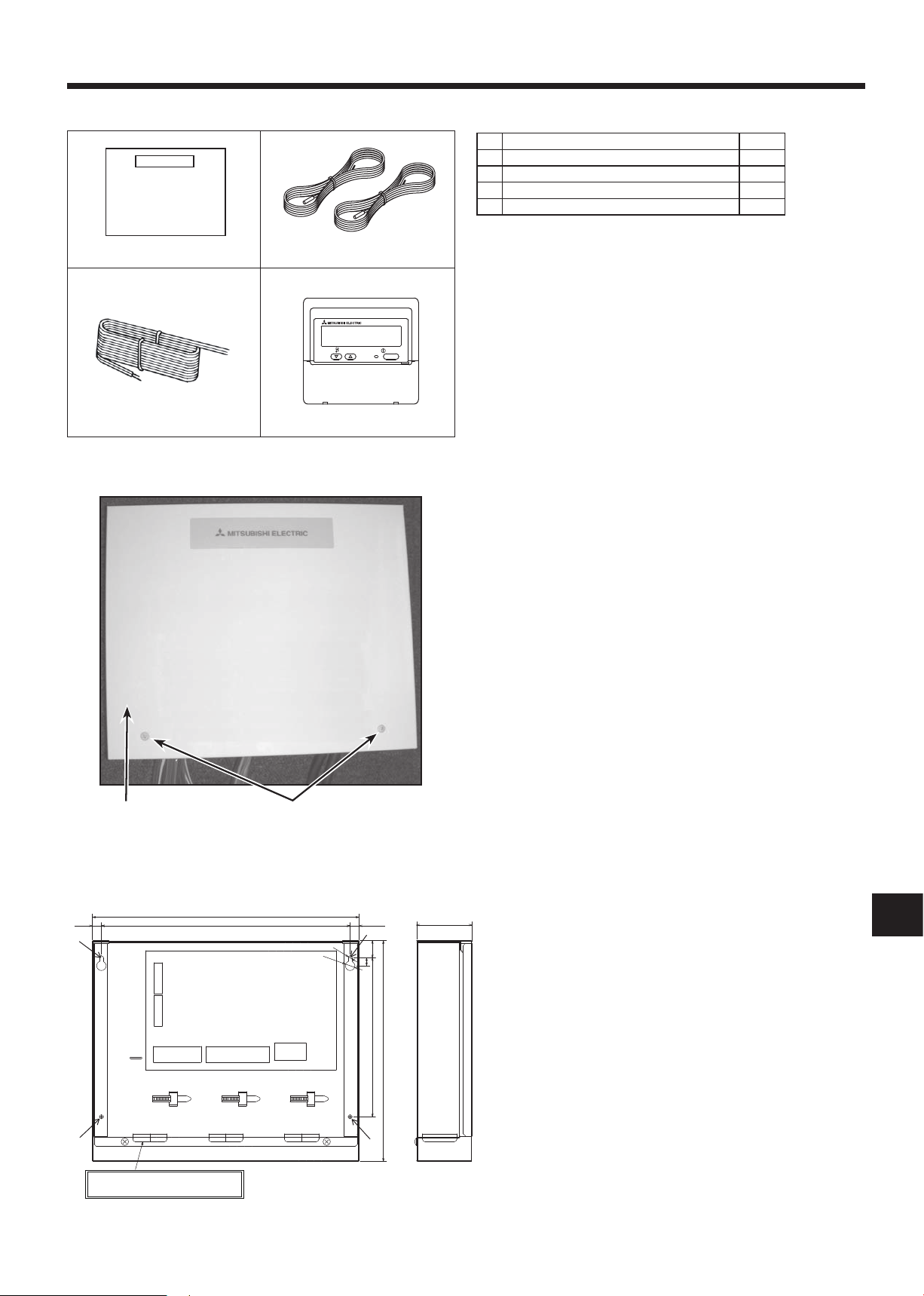
2.1. Check the parts (Fig. 2-1)
The FTC unit should be supplied with the following parts.
Part Name Q'ty
FTC unit 1
1
Thermistor 2
2
Remote controller cable(5m) 1
3
Remote controller 1
4
2.2. Choosing the FTC unit installation location
• Do not install the FTC unit in outdoor location as it is designed for in-
door installation only. (It is not waterproof against raindrop.)
• Avoid locations where the unit is exposed to direct sunlight or other
sources of heat.
• Select a location where easy wiring access to the power source is
available.
• Avoid locations where combustible gases may leak, be produced,
ow,oraccumulate.
• Select a level location that can bear the weight and vibration of the
unit.
• Avoid locations where the unit is exposed to oil, steam, or sulfuric gas.
• Do not install in location that is hot or humid for long periods of time.
B A
Photo.2-1
2.3. Installing the FTC unit (Fig. 2-2, Photo.2-1)
1. Remove 2 screws from FTC unit and remove the cover.
2. Install the 4 screws (locally supplied) in 4 holes.
Screw B Cover
A
Hole for installation
C
Fig.2-2
4
BG
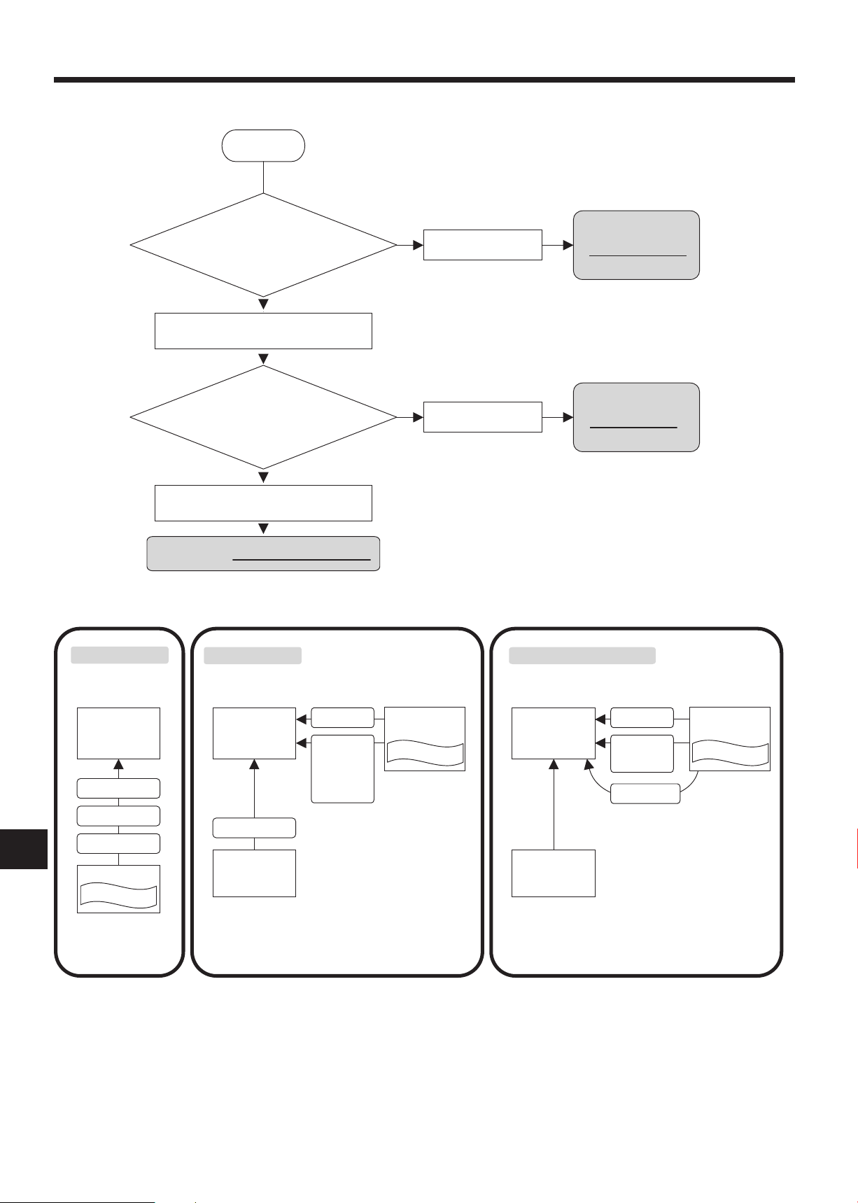
3. System
+In this system,
• Heating ECO mode of FTC is
not available.
• It is NOT necessary to switch
operation mode to realize
Hot water mode, Anti freeze
mode and Heating ECO mode.
Simply change the target temp.
by Analog signal.
Start
‘Target flow temperature’ is set…
By remote controller
By remote controller
Your system is
BASIC SYSTEM.
Your system is
SIMPLE SYSTEM.
Your system is ANALOG TEMP. SYSTEM.
Remote controller
FTC PCB BOX FTC PCB BOX FTC PCB BOX
Remote controller
System controller
(locally supplied)
SIMPLE SYSTEM BASIC SYSTEM ANALOG TEMP. SYSTEM
ON/OFF
Operation mode
Operation mode
- Heating
- Heating ECO
- Hot water
- Anti freeze
- Cooling
Operation mode
- Heating +
- Cooling
Target flow temp.
Target flow temp.
Target flow temp.
ON/OFF
Remote controller
ON/OFF
By Non-voltage
Contact signals
By Non-voltage
Contact signals
End user interface
End user interface
System controller
(locally supplied)
End user interface
Topreset
- target temp. for each mode
- target temp. parameters
(See Page22-23 for details)
Topreset
- analog signal parameters
(See Page24 for details)
Analog signal
4-20mA/1-5V/0-10V
Heat Pump switch ON/OFF
and the operation mode
change is done…
By external signals from local controller
(non-voltage contact signals)
By external signals from local controller
(Analog signal:4-20mA/ 1-5V/ 0-10V)
Tostart,checkyoursystemtypebyfollowingtheowchartbelow.(FTCcanbeusedfor3typesofsystems.)

5
BG
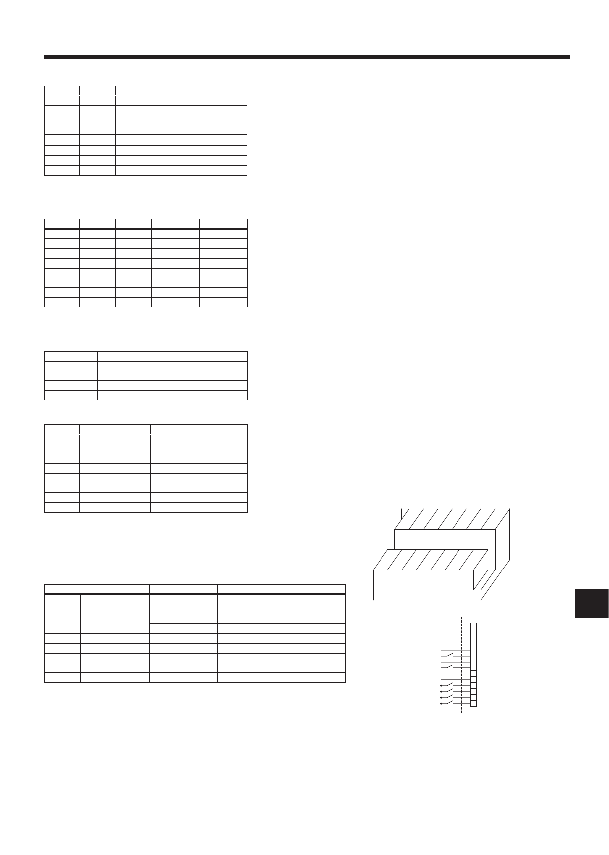
3. System
System System diagram
Power
supplies
Thermistor
(TH1, TH2)
Switch
setting
External
input
External
output
Outdoor
unit
BASIC
SPLIT type
PACKAGED
type
SPLIT type
PACKAGED
type
SPLIT type
PACKAGED
type
ANALOG
TEMP.
SIMPLE
4.6
4.6
4.6
4.6
4.6
4.6
4.6
4.6
4.6
4.6
4.6
4.6
4.4
4.4
4.4
4.4
4.4
4.4
4.4
4.4
4.4
4.4
4.4
4.4
4.2.1
4.2.2
4.2.1
4.2.2
4.2.1
4.2.1
4.2.1
4.2.2
4.2.1
4.2.2
4.2.1
4.2.1
4.2.1
4.2.2
4.2.1
4.2.2
4.2.1
4.2.1
4.1
4.1.1
4.1
4.1.2
4.1
4.1.1
4.1
4.1.2
4.1
4.1.1
4.1
4.1.2
4.1
4.1.1
4.1
4.1.2
4.1
4.1.1
4.1
4.1.2
4.1
4.1.1
4.1
4.1.2
4.5.1
4.5.1
4.5.1
4.5.1
4.5.1
4.5.2
4.5.1
4.5.2
4.5.1
4.5.2
4.5.1
4.5.2
FTC
TH1
FTC Outdoor unit
FTC Outdoor unit
FTC Outdoor unit
FTC Outdoor unit
FTC Outdoor unit
FTC Outdoor unit
FTC Outdoor unit
FTC Outdoor unit
FTC Outdoor unit
FTC Outdoor unit
FTC Outdoor unit
FTC Outdoor unit
TH2
Local controller
ON/OFF
MODE
Remote controller
(PAR-W21MAA)
Remote controller
(PAR-W21MAA)
Remote controller
(PAR-W21MAA)
Remote controller
(PAR-W21MAA)
Remote controller
(PAR-W21MAA)
Remote controller
(PAR-W21MAA)
Remote controller
(PAR-W21MAA)
Remote controller
(PAR-W21MAA)
Remote controller
(PAR-W21MAA)
Remote controller
(PAR-W21MAA)
Remote controller
(PAR-W21MAA)
Remote controller
(PAR-W21MAA)
FTC
TH1
FTC
TH1
FTC
TH1
FTC
TH1
FTC
TH1
TH2
FTC
TH1
TH2
Local controller
ON/OFF
Temp.
FTC
TH1
TH2
FTC
TH1
TH2
FTC
TH1
TH2
FTC
TH1
FTC
TH1
—
—
—
—
( )
Local controller
ON/OFF
MODE
( )
Local controller
ON/OFF
MODE
( )
( )
Local controller
ON/OFF
MODE
( )
Local controller
ON/OFF
Temp.
( )
Local controller
ON/OFF
Temp.
( )
Local controller
ON/OFF
Temp.
( )
Refer to the relevant sections for details according to your system type.
SPLIT type : the standard outdoor unit without a plate HEX(Refrigetant-water HEX) inside
PACKAGED type : the Air to Water outdoor unit with a plate HEX(Refrigetant-water HEX) inside
6
BG
4. Electrical work
S1
S2
L
N
S1
S2
S3
S3
A B C
D
E
F
FTC unit-Outdoor unit
FTC unit model
*1
FTC unit-Outdoor unit earth
*1
FTC unit-Outdoor unit S1-S2
*2
FTC unit-Outdoor unit S2-S3
*2
PAC-IF021B-E
AC 230 V
DC24 V
1 × Min.1.5
3× 1.5 (polar)
Circuit
rating
Wiring
Wire No. × size
(mm
2
)
NL
S2 S3S1
E: FTC unit/outdoor unit
connecting cables
Earth cable
TB6
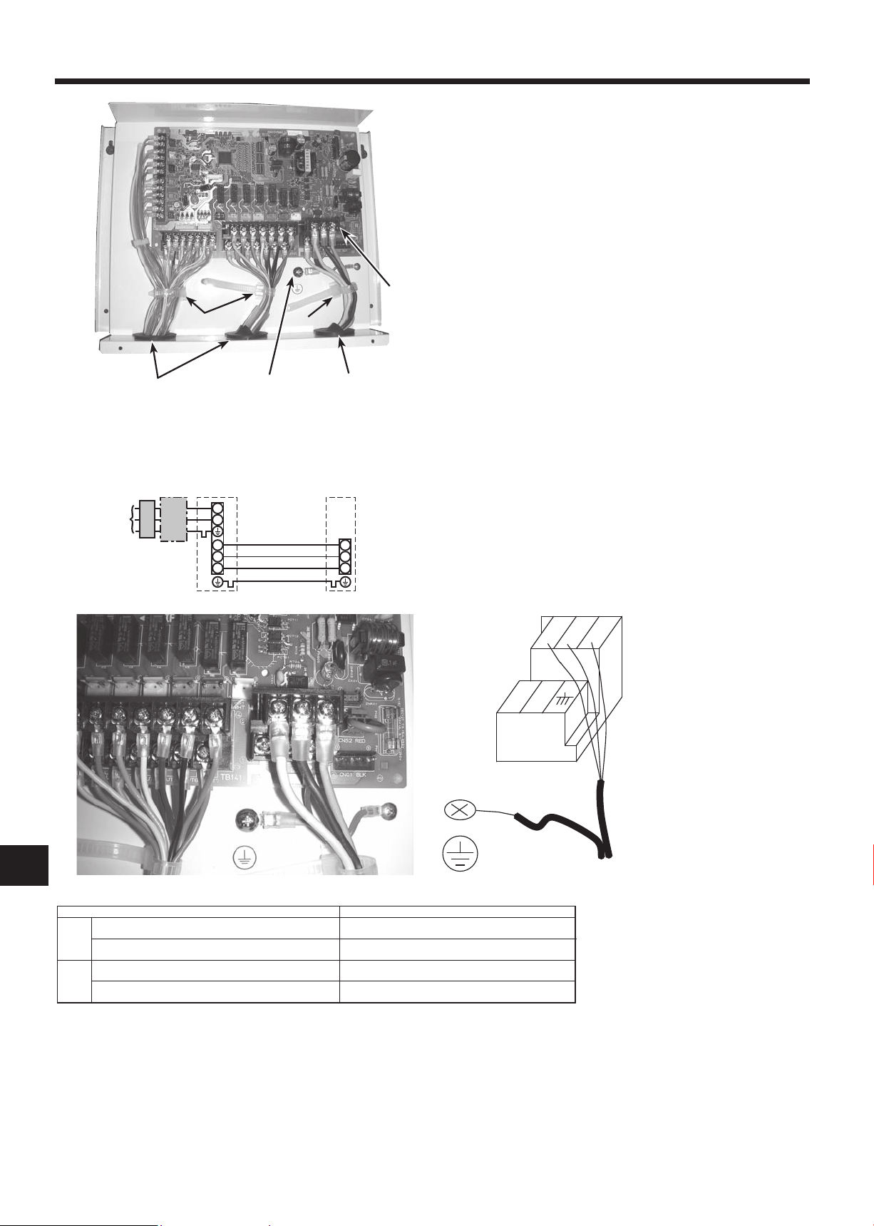
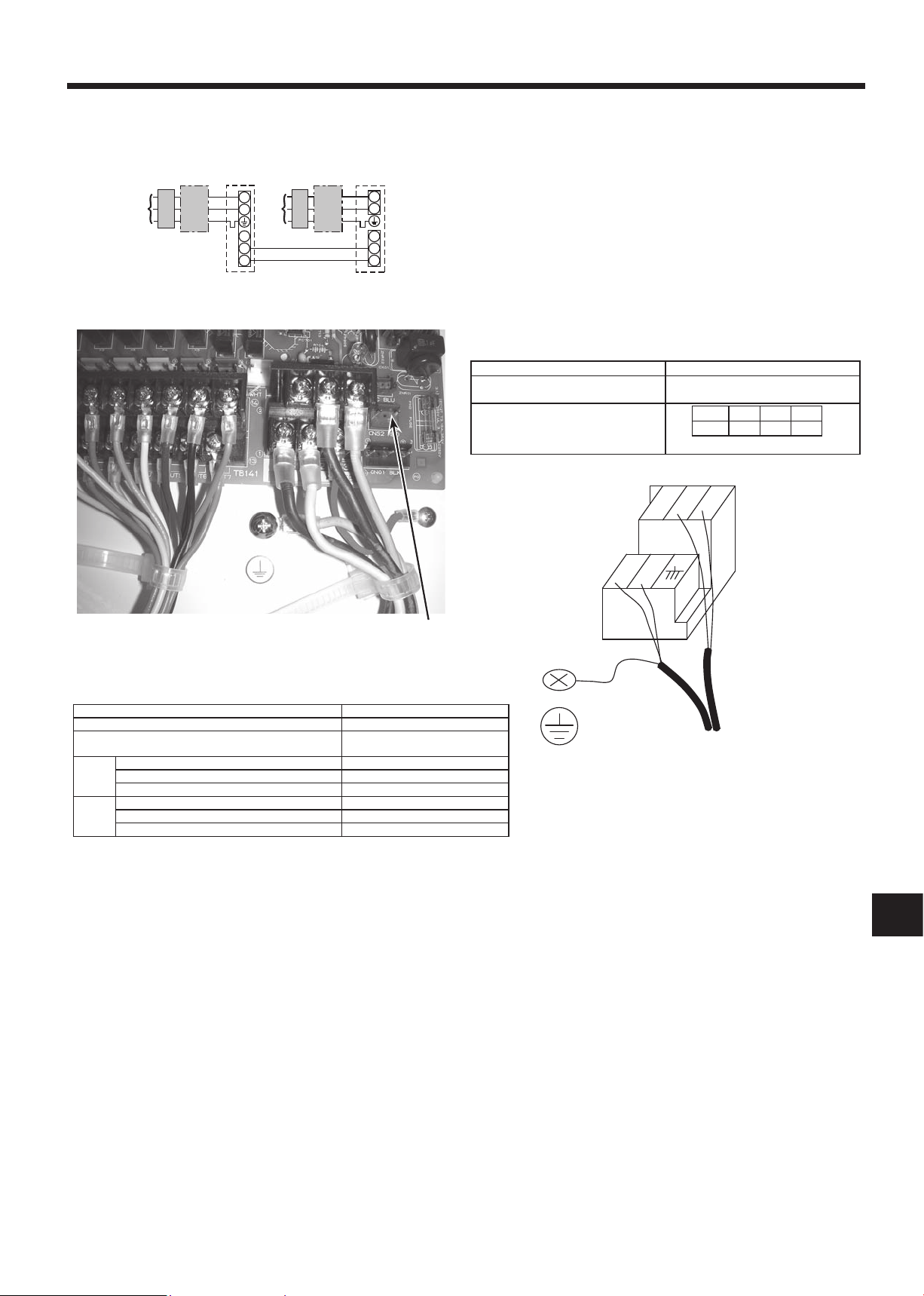
4.1. FTC (Photo. 4-1)
1. Remove the cover.
2. Wire the power cable and control cable separately through the respective wiring inlets given in the photo.
• Make sure to put screws tightly.
Inlet for control cable
A
Inlet for power
B
Clamp
C
FTC / Outdoor unit connecting terminals
D
Earth terminal
E
D
C
C
Photo.4-1
A
E
4.1.1. FTC unit power supplied from outdoor unit
The following connection patterns are available.
The outdoor unit must be powered properly.(Details are shown in its installation manual.)
B
A Outdoor unit power supply
B Earth leakage breaker
C Wiring circuit breaker or isolating switch
D Outdoor unit
E FTC unit/outdoor unit connecting cables
F FTC unit
*1. Max. 80 m
*2.TheguresareNOTalwaysagainsttheground.
S3 terminal has DC 24 V against S2 terminal. However between S3 and S1, these terminals are not electrically insulated by the transformer or other device.
Notes: 1. Wiring size must comply with the applicable local and national codes.
2. Power supply cables and FTC unit/outdoor unit connecting cables shall not be lighter than polychloroprene sheathed exible ca-
3. Install an earth wire longer than other cables.
ble. (Design 60245 IEC 57)
Photo.4-2
7
BG
4. Electrical work
S1
S2
L
N
L
N
S1
S2
S3
S3
A
CB
D
GEB
C
F
NL
S2 S3S1
E: FTC unit/outdoor unit
connecting cable
Power Supply Cables
TB6
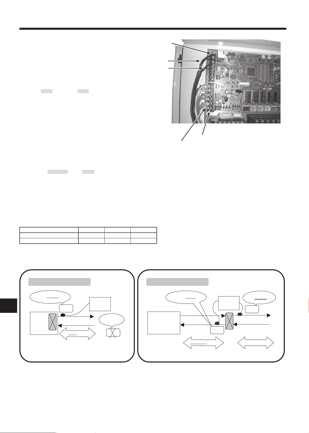
4.1.2. Separate FTC unit/outdoor unit power supplies
The following connection patterns are available.
The outdoor unit power must be powered properly(Details are shown in its installation manual).
A Outdoor unit power supply
B Earth leakage breaker
C Wiring circuit breaker or isolating switch
D Outdoor unit
E FTC unit/outdoor unit connecting cables
F FTC unit
G FTC unit power supply
If the FTC and outdoor units have separate power supplies, refer to the
table below.
FTC unit controller connector (CNS2)
connection change
Outdoor unit DIP switch settings (when
using separate FTC unit/outdoor unit
power supplies only)
Separatepowersupplyspecications
Disconnected
ON 3
OFF 1 2
Set the SW8-3 to ON.
(SW8)
Photo.4-3
FTC unit model PAC-IF021B-E
FTC unit power supply ~/N (Single Phase), 50 Hz, 230 V
FTC unit input capacity
Main switch (Breaker)
)
2
FTC unit power supply & earth 3 × Min. 1.5
(mm
FTC unit-Outdoor unit *2 2 × Min. 0.3
Wiring
Wire No. ×
size
FTC unit-Outdoor unit earth –
FTC unit L-N *3 AC 230 V
FTC unit-Outdoor unit S1-S2 *3 –
rating
Circuit
FTC unit-Outdoor unit S2-S3 *3 DC24 V
*1. A breaker with at least 3.0mm contact separation in each pole shall be provided. Use earth leakage breaker (NV).
*2. Max. 120 m
*3.TheguresareNOTalwaysagainsttheground.
*1 16 A
CNS2
Notes: 1. Wiring size must comply with the applicable local and national code.
2. Power supply cables and FTC unit/outdoor unit connecting cables shall not be lighter than polychloroprene sheathed exible cable. (Design 60245 IEC 57)
3. Install an earth wire longer than other cables.
8
BG
4. Electrical work
FTC
Outdoor unit
TH1
TH2
*1
*1
Water piping
Refrigerant piping
Water OUTLET side
Refrigerant LIQUID side
FTC
Outdoor unit
Packaged type
(with a refrigerant-water HEX inside)
SPLIT type
(without refrigerant-water
HEX inside)
*1 Refrigerant-water HEX
*1 Refrigerant-water HEX
TH1
Water piping
Water OUTLET side
TH2
TH2:
not necessary
PACKAGED type outdoor unit SPLIT type outdoor unit
4.2. Connecting thermistor cable
Connect the thermistor 2 for the FTC controller.
4.2.1. Connecting the actual ow water temp. thermistor (TH1)
Connectthethermistorfortheactualowwatertemp.to1and2onthe
terminal block (TB61) on the FTC controller.
When the thermistor cables are too long, cut them at the appropriate
length.
Do not bind them in the FTC unit.
<Thermistor position>
Put TH1 on water piping (water outlet side).
Note: Be sure to attach the TH1 where it detects Flow temp.(Water
oulet side) correctly.
4.2.2. Connecting the pipe temp. thermistor (TH2)
Connect the thermistor for the refrigerant pipe temp. to 3 and 4 on the
terminal block (TB61) on the FTC (PCB).
For packaged Outdoor unit : It is not necessary to connect TH2.
For split Outdoor unit : Connect TH2.
When the thermistor cables supplied with FTC are too long, cut them to
the appropriate length.
Do not bind them in the FTC unit.
<Thermistor position>
Put the TH2 on refrigerant piping (Liquid side).
It is better to protect the thermistor with heat insulating materials not to be affected by the ambient temperature.
Note: Be sure to attach the TH2 where it detects Refrigerant piping temp. (Liquid side) correctly.
TB61
TH1
TH2
Photo.4-4
TB62
Wired remote controller cable
Caution:
Do not route the thermistor cables together with power cables.
The sensor part of the thermistor should be installed where user must not touch.
(It is separated by the supplementary insulation from where user may touch.)
<Thermistor position and necessity>
Outdoor unit TH1 TH2 TH5
PACKAGED type Ο Х Х
SPLIT type Ο Ο Х
Ο:Necessary.Connectthethermistor.
Х:Notnecessary.Thethermistorisnotneededtoconnect.
9
BG
4. Electrical work
3030
30120
83.5
B-1. B-2.
Fig. 4-2
B TB
Fig. 4-1
Fig. 4-3
46
A 6
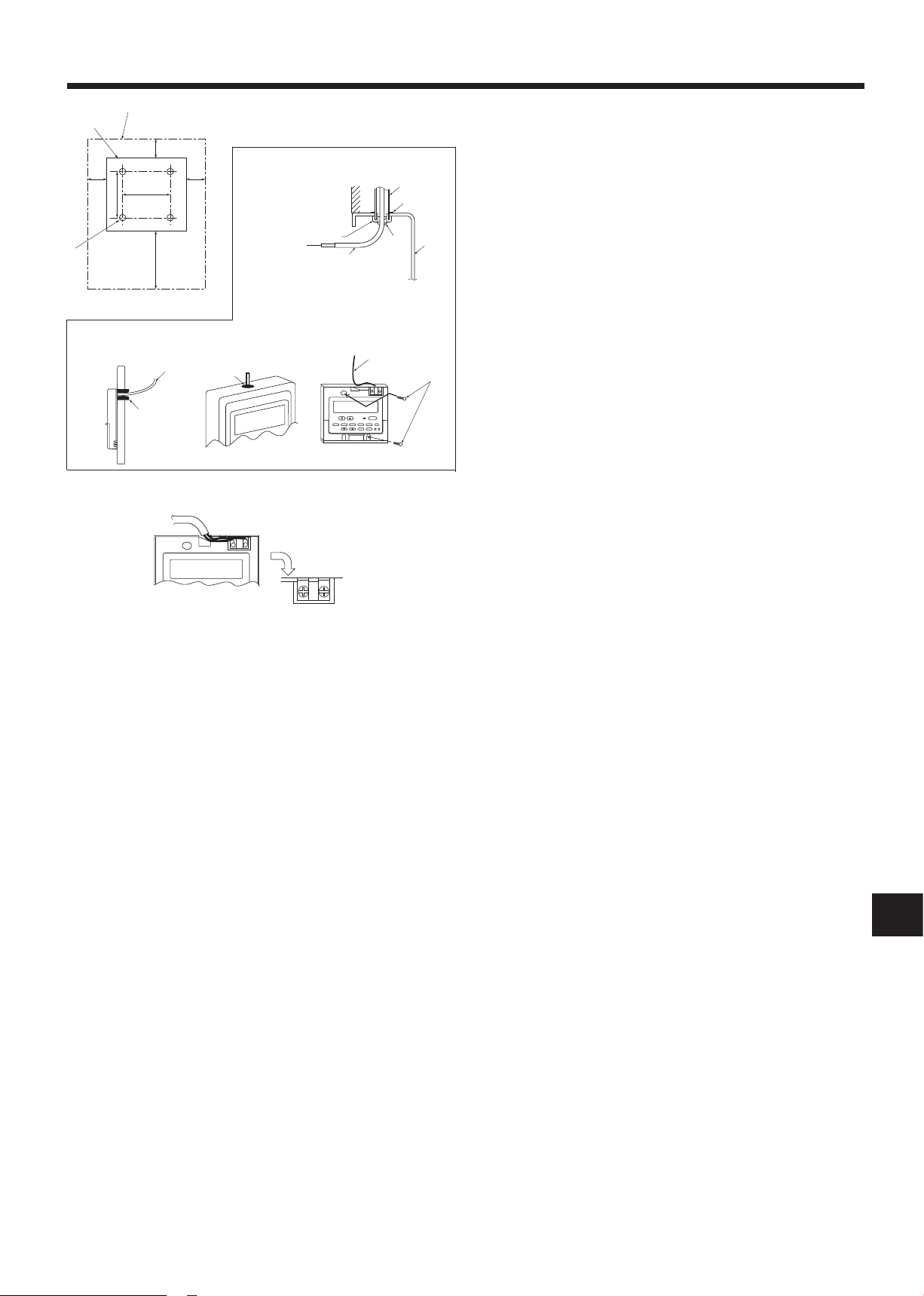
4.3. Connecting the wired remote controller
4.3.1. Connecting the wired remote controller cable to FTC
Connect the wired remote controller cable to 5 and 6 on the terminal
block (TB62) on the FTC controller.(Photo. 4-4)
Wiring wire No.×size(mm2) : 2×0.3(Non-polar)
The 5m wire is attached as an accessory. Max. 500 m
Wiring size must comply with the applicable local and national codes.
Circuit rating: DC12V
Circuit rating is NOT always against the ground.
4.3.2. For wired remote controller
1) Installing procedures
(1) Select an installing position for the remote controller. (Fig. 4-1)
► Procure the following parts locally:
2 piece switch box
Thin copper conduit tube
Lock nuts and bushings
[Fig.4-1]
Remotecontrollerprole
A
Required clearances surrounding the remote controller
B
Installation pitch
C
(2) Seal the service entrance for the remote controller cable with putty
to prevent possible invasion of dew drops, water, cockroaches or insects. (Fig. 4-2)
For installation in the switch box
A
For direct installation on the wall, select one of the followings:
B
• Prepare a hole through the wall to pass the remote controller cable (in
order to take out the remote controller cable from the back), then seal
the hole with putty.
• Take out the remote controller cable through the cut-out upper case,
then seal the cut-out notch with putty.
B-1. To lead the remote controller cable from the back of the con-
troller
B-2. To take out the remote controller cable through the upper por-
tion
[Fig.4-2]
Wall
C
Conduit
D
Lock nut
E
Bushing
F
2) Connecting procedures (Fig. 4-3)
Connect the remote controller cable to the terminal block.
1
To TB62 No.5 and 6 on the FTC unit
A
TB6 (No polarity)
B
Switch box
G
Remote controller cable
H
Seal with putty
I
Wood screw
J
10
BG
4. Electrical work
4.4. Switch setting of FTC
Set the dip switch on the FTC (PCB) according to the following table.
System ON/OFF
BASIC External input
ANALOG
TEMP.
BASIC
and
SIMPLE
SIMPLE Wired remote controller Wired remote controller Wired remote controller SPLIT type OFF OFF OFF OFF OFF OFF
Input
(non-voltage contact)
External input
(non-voltage contact)
External input or
4-20mA *1
External input or
1-5V *2
External input External input
External input and *3
Wired remote controller
External input and *3
Wired remote controller
*1: 4-20mA····OFF:0~2mA
*2: 1-5V····OFF:0~0.5V
*3: The command from the external input is prior to the one from the wired remote controller.
*4: SPLIT type : the standard outdoor unit without a plate HEX(refrigerant-water) inside.
PACKAGED type : the Air to Water outdoor unit with a plate of HEX(refrigerant-water) inside
OTHER SWITCH SETTING
SW1-3 Prohibition of Cooling mode
SW1-3=OFF : Operation mode Heating/HeatingECO/HotWater/Anti-freeze/Cooling
SW1-3=ON : Operation mode Heating/HeatingECO/HotWater/Anti-freeze
SW1-4 SW3-4,5,8 Not in use. Set to OFF. (Initial setting)
SW3-7 Not in use. Set to ON. (Initial setting)
Change mode
Input
External input
(non-voltage contact)
External input
(non-voltage contact)
External input
(non-voltage contact)
External input
(non-voltage contact)
(non-voltage contact)
External input and *3
Wired remote controller
External input and *3
Wired remote controller
Change TEMP.
Input
DIP switch on PCB
SW2-1~8, SW3-1~3
Wired remote controller SPLIT type ON OFF OFF OFF OFF OFF
4-20mA SPLIT type OFF ON OFF OFF ON ON
1-5V SPLIT type OFF ON OFF OFF OFF ON
0-10V SPLIT type ON ON OFF OFF OFF OFF
DIP switch on PCB
SW2-1~8, SW3-1~3
Wired remote controller SPLIT type OFF OFF OFF OFF OFF OFF
Outdoor unit *4 SW1-1 SW1-2 SW1-5 SW1-6 SW6-1 SW6-2
SPLIT type ON OFF OFF ON OFF OFF
PACKAGED type ON OFF ON ON OFF OFF
PACKAGED type ON OFF ON OFF OFF OFF
PACKAGED type OFF ON ON OFF ON ON
PACKAGED type OFF ON ON OFF OFF ON
PACKAGED type ON ON ON OFF OFF OFF
SPLIT type OFF OFF OFF ON OFF OFF
PACKAGED type OFF OFF ON ON OFF OFF
PACKAGED type OFF OFF ON OFF OFF OFF
PACKAGED type OFF OFF ON OFF OFF OFF
SW6
TB61
SW3-6 Logic of Forced Comp. OFF external signal(TB142 5-6)
SW3-6 TB142 No.5-6 input Item
OFF(open) Normal
OFF
ON(short) Forced Comp. OFF
OFF(open) Forced Comp. OFF
ON
ON(short) Normal
SW1-6,7,8 Set temperature range
SW1-6=OFF Set temperature range with wired remote controller
TH1
TH2
Photo.4-5
SW1-6=ON Set temperature table with DIP switch of FTC
SW1-6 SW1-7 SW1-8 Temperature range with wired remote controller Temperature table
OFF OFF OFF Upper55˚C/lower20˚C Upper45˚C/lower5˚C Upper25˚C/lower5˚C —
OFF ON OFF Upper60˚C/lower20˚C*1 Upper45˚C/lower5˚C Upper25˚C/lower5˚C —
OFF OFF ON Upper50˚C/lower20˚C Upper45˚C/lower5˚C Upper25˚C/lower5˚C —
OFF ON ON — — — —
ON OFF OFF — — — Table
ON ON OFF — — — Table
ON OFF ON — — — —
ON ON ON — — — —
Heating/HeatingECO/Hot Water Anti-Freeze Cooling
SW2-1~8, SW3-1~3
1
2
*1.Don’t use this setting when you use the standard outdoor unit without a plate HEX(Refrigerant-water) inside.
SW1
SW2
SW3
11
BG
4. Electrical work
TB142
FTC
11
10
12
13
14
At site
HeatingECO →
Anti-Freeze →
Hot Water →
Heating →
6
5
7
8
9
2
1
3
4
Forced Comp. OFF →
Cooling →
3 5 7 9 11 131
42 6 8 10 12 14
TB142
SW2-1~8 SW3-1~3 Fixed set temperature with DIP switch of FTC (Available when SW1-6 is ON)
SW2-1~3 Fixed set temperature for Heating mode (Table1~2 depends on SW1-7,8.)
SW2-1 SW2-2 SW2-3 Table
1
OFF OFF OFF 25 ºC 25 ºC
ON OFF OFF 30 ºC 30 ºC
OFF ON OFF 35 ºC 35 ºC
ON ON OFF 40 ºC 40 ºC
OFF OFF ON 45 ºC 45 ºC
ON OFF ON 50 ºC 50 ºC
OFF ON ON 55 ºC 55 ºC
ON ON ON 60 ºC *1 60 ºC *1
The selectable temperature range for Heating mode depends on outdoor unit type.
*1 Do not use this setting when you use the standard outdoor unit without a plate HEX(refrigerant-water) inside.
SW2-4~6 Fixed set temperature for Hot Water mode (Table1~2 depends on SW1-7,8.)
SW2-4 SW2-5 SW2-6 Table
OFF OFF OFF 46 ºC 25 ºC
ON OFF OFF 48 ºC 30 ºC
OFF ON OFF 50 ºC 35 ºC
ON ON OFF 52 ºC 40 ºC
OFF OFF ON 54 ºC 45 ºC
ON OFF ON 56 ºC 50 ºC
OFF ON ON 58 ºC 55 ºC
ON ON ON 60 ºC *1 60 ºC *1
1
The selectable temperature range for Hot Water mode depends on outdoor unit type.
*1 Do not use this setting when you use the standard outdoor unit without a plate HEX(refrigerant-water) inside.
Table
Table
2
2
SW2-7,8 Fixed set temperature for Anti-freeze mode (Table1~2 depends on SW1-7,8.)
SW2-7 SW2-8 Table
1
OFF OFF 5 ºC 5 ºC
ON OFF 10 ºC 10 ºC
OFF ON 15 ºC 15 ºC
ON ON 20 ºC 20 ºC
Table
2
SW3-1~3 Fixed set temperature for Cooling mode(Table1~2 depends on SW1-7,8.)
SW3-1 SW3-2 SW3-3 Table
1
OFF OFF OFF 7 ºC 7 ºC
ON OFF OFF 10 ºC 10 ºC
OFF ON OFF 12 ºC 12 ºC
ON ON OFF 15 ºC 15 ºC
OFF OFF ON 18 ºC 18 ºC
ON OFF ON 20 ºC 20 ºC
OFF ON ON 22 ºC 22 ºC
ON ON ON 25 ºC 25 ºC
Table
2
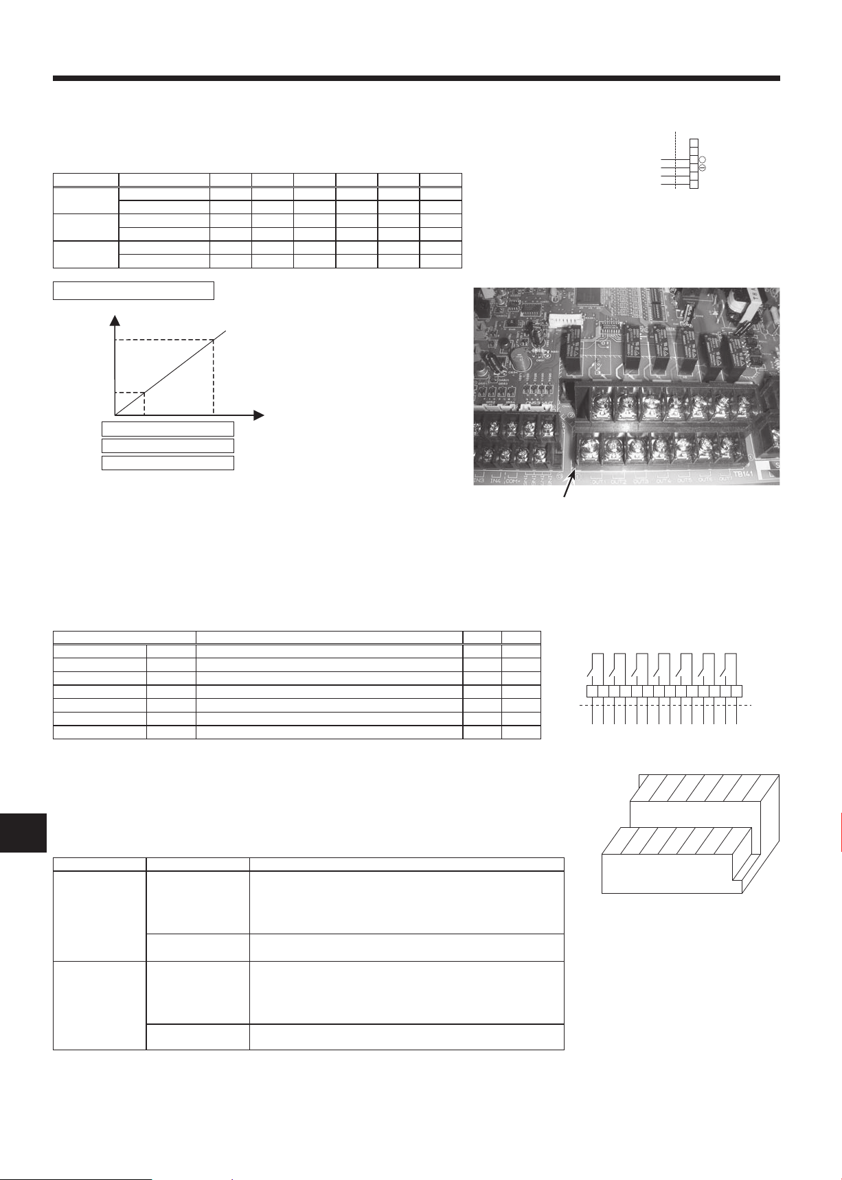
4.5. Connecting external input
FTC can be operated by following external input.
4.5.1 EXTERNAL INPUT ( Contact signal )
TB142 OFF ON Remark
1-2 (IN1) — — Not in use
3-4 (IN2) — — Not in use
5-6 (IN3) Normal Forced Comp. OFF SW3-6=OFF
7-8 (IN4) OFF Cooling
10-11 (COM-IN5) OFF Heating
10-12 (COM-IN6) OFF Heating ECO *1
10-13 (COM-IN7) OFF Hot Water
10-14 (COM-IN8) OFF Anti-Freeze
*1 Heating ECO mode sets the set temperature depending on the outdoor temperature.
Forced Comp. OFF Normal SW3-6=ON
12
BG
4. Electrical work
FTCAt site
6
5
2
1
4
3
TB62
4-20mA/1-5V/0-10V
(
Wired remote controller
(
+
0mA -- 4mA --------------- 20mA
0V-------1V------------------- 5V
0V------------------10V
No.1 Temp.
Stop
4-20mA
Refer to the section 8 for details about No1, 2 Temp.
The selectable set temperature range depends on SW1-7, 8.
1-5V
0-10V
No.2 Temp.
FLOW TEMP.
ANALOG
SIGNAL
1FTC
TB141
At site
X1
2 3X24 5X36 7X48 9
X5 X6 X7
1413121110
3 5 7 9 11 131
42
TB141
6 8 10 12 14
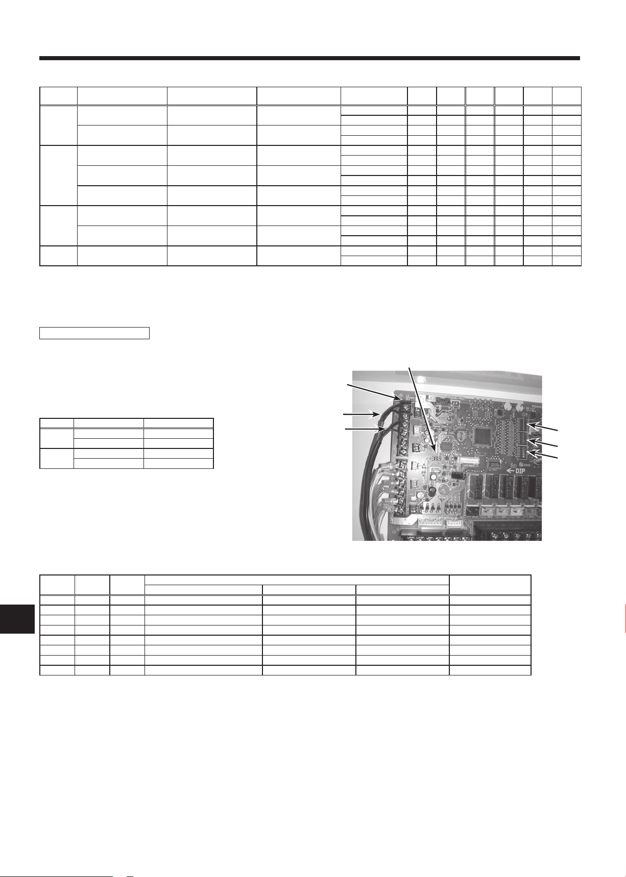
4.5.2 EXTERNAL INPUT ( analog signal ) 4-20mA / 1-5V / 0-10V
Connect the transmission cables to No. 3 and 4 on the terminal block (TB62).
No. 3 on the terminal block(TB62) : Plus side
No. 4 on the terminal block(TB62) : Minus side (Reference side)
Switch setting
Input Outdoor unit SW1-1 SW1-2 SW1-5 SW1-6 SW6-1 SW6-2
4-20mA SPLIT type OFF ON OFF OFF ON ON
1-5V SPLIT type OFF ON OFF OFF OFF ON
0-10V SPLIT type ON ON OFF OFF OFF OFF
4-20mA / 1-5V / 0-10V setting
PACKAGED type OFF ON ON OFF ON ON
PACKAGED type OFF ON ON OFF OFF ON
PACKAGED type ON ON ON OFF OFF OFF
Caution:
The external input signals are separated by basic insulation from power supply for the unit.
The external input signals should be separated by supplementary insulation from where user may touch in case that it is installed where
user may touch.
Connect the terminals by using the ring terminals and also insulate the cables of adjoining terminals when wiring to terminal block.
4.6. Connecting external output (Photo. 4-6)
TB141 Item OFF ON
1-2 (OUT1) X1 Operation Output OFF ON
3-4 (OUT2) X2 Error Output Normal Error
5-6 (OUT3) X3 Comp. Output OFF ON
7-8 (OUT4) X4 Defrost Output OFF ON
9-10 (OUT5) X5 Mode(Cooling) Output OFF ON
11-12 (OUT6) X6 Mode(Heating/HeatingECO/Hot Water/ Anti-Freeze) Output OFF ON
13-14 (OUT7) X7 — — —
Note :
External output signals are separated by basic insulation from other circuit of interface.
Caution :
When 2 or more external outputs are used, the power supply on the output side should be the same.
4.7. Wiring specication of External output / External input
Locally supplied parts
Item Name Modelandspecications
External output
function
External input
function
External output signal
wire
Display lamp, etc. Non-voltage Contact AC220-240V (DC30V), 1A or less
External input signal
wire
Switch Non-voltage "a" contact signals
Use sheathed vinyl coated cord or cable.
Max. 50m
Wire type : CV, CVS or equivalent
Wire size : Stranded wire 0.5mm2 to 1.25mm
Solid wire: {0.65mm to {1.2mm
2
*Connect the surge absorber according to the load at site.
Use sheathed vinyl coated cord or cable.
Max. 10m
Wire type :CV, CVS or equivalent
Wire size : Stranded wire 0.5mm2 to 1.25mm
Solid wire : {0.65mm to {1.2mm
Remote switch : minimum applicable load DC 12V, 1mA
2
TB141
Photo.4-6
13
BG
5. Before test run
ON/OFF
TEMP.
ERROR CODE
5.1. Check
After completing installation and the wiring and piping of the local application and outdoor units, check for refrigerant leakage, looseness in the power
supply or control wiring, wrong polarity, and no disconnection of one phase in the supply.
Usea500-voltmegohmmetertocheckthattheresistancebetweenthepowersupplyterminalsandgroundisatleast1.0MΩ.
Warning:
Do not use the system if the insulation resistance is less than 1.0MΩ.
Caution:
Do not carry out this test on the control wiring (low voltage circuit) terminals.
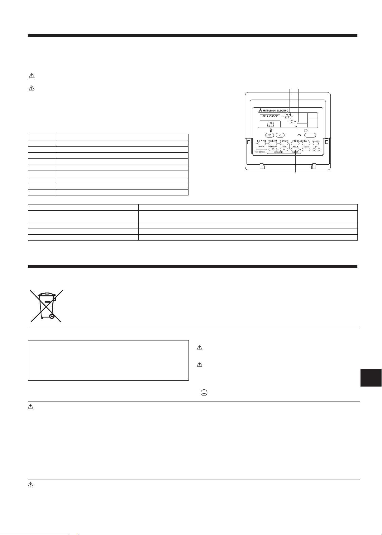
5.2. Self-check
Turn on the power.
1
Press [CHECK] button twice.
2
Press[CHECK]buttontwicetonishself-check.
3
CHECK button
A
Check code Symptom
P1 Flow water (TH1) sensor error
P2 Refrigerant liquid Pipe (TH2) sensor error
P6 Freezing/Overheating protection operation
Fb FTC unit control system error (memory error, etc.)
E0~E5 Signal transmission failure between remote controller and FTC.
E6~EF Signal transmission failure between outdoor unit and FTC.
– – – – No trouble generated in the past.
FFFF No corresponding unit
U*, F* Outdoor unit failure. Refer to the outdoor unit wiring diagram.
For description of each LED(LED1~5) provided on the FTC, refer to the following table.
LED 1 (Power for microcomputer) Indicates whether control power is supplied. Make sure that this LED is always lit.
LED 2 (Power for remote controller) Indicates whether power is supplied to the remote cotroller. This LED lights only in the case of the FTC unit
LED 3(Communication between FTC and outdoor unit) Indicates state of communication between the FTC and outdoor unit. Make sure that this LED is always blinking.
LED 4 —
LED 5 —
IC : FTC unit OC : Outdoor unit C Check code
B
which is connected to the outdoor unit refrigerant address “0“.
6. Remote controller operation
Note (Marking for
WEEE)
6.1 Safety precautions
► Before installing the unit, make sure you read all the “Safety Precau-
tions”.
► The “Safety Precautions” provide very important points regarding
safety. Make sure you follow them.
► Please report to or take consent by the supply authority before connec
tion to the system.
Warning:
• For appliances not accessible to the general public.
• The unit must not be installed by the user. Ask the dealer or an authorized
company to install the unit. If the unit is installed improperly, water leak-
age, electric shock or re may result.
• Do not stand on, or place any items on the unit.
• Do not splash water over the unit and do not touch the unit with wet hands.
An electric shock may result.
• Do not spray combustible gas close to the unit. Fire may result.
• Do not place a gas heater or any other open-ame appliance where it will
be exposed to the air discharged from the unit. Incomplete combustion
may result.
• Do not remove the front panel or the fan guard from the outdoor unit when
it is running.
This symbol mark is for EU countries only.
This symbol mark is according to the directive 2002/96/EC Article 10 Information for users and Annex IV.
Your MITSUBISHI ELECTRIC product is designed and manufactured with high quality materials and components which can be recycled and reused.
This symbol means that electrical and electronic equipment, at their end-of-life, should be disposed of separately from your household waste.
Please, dispose of this equipment at your local community waste collection/recycling centre.
In the European Union there are separate collection systems for used electrical and electronic product.
Please, help us to conserve the environment we live in!
-
Symbols used in the text
Warning:
Describes precautions that should be observed to prevent danger of injury or
death to the user.
Caution:
Describes precautions that should be observed to prevent damage to the
unit.
Symbols used in the illustrations
: Indicates a part which must be grounded.
• When you notice exceptionally abnormal noise or vibration, stop opera
tion, turn off the power switch, and contact your dealer.
• Never insert ngers, sticks etc. into the intakes or outlets.
• If you detect odd smells, stop using the unit, turn off the power switch and
consult your dealer. Otherwise, a breakdown, electric shock or re may
result.
• This air conditioner is NOT intended for use by children or inrm persons
without supervision.
• Young children must be supervised to ensure that they do not play with
the air conditioner.
• If the refrigeration gas blows out or leaks, stop the operation of the air
conditioner, thoroughly ventilate the room, and contact your dealer.
• Do not install in location that is hot or humid for long periods of time.
-
Caution:
• Do not use any sharp object to push the buttons, as this may damage the
remote controller.
• Never block or cover the indoor or outdoor unit’s intakes or outlets.
Disposing of the unit
When you need to dispose of the unit, consult your dealer.
14
BG
˚F˚C
˚F˚C
ERROR CODE
AFTER
TIMER
TIME SUN MON TUE WED THU FRI SAT
ON
OFF
Hr
AFTER
FUNCTION
WEEKLY
ON/OFF
TEMP.
6. Remote controller operation
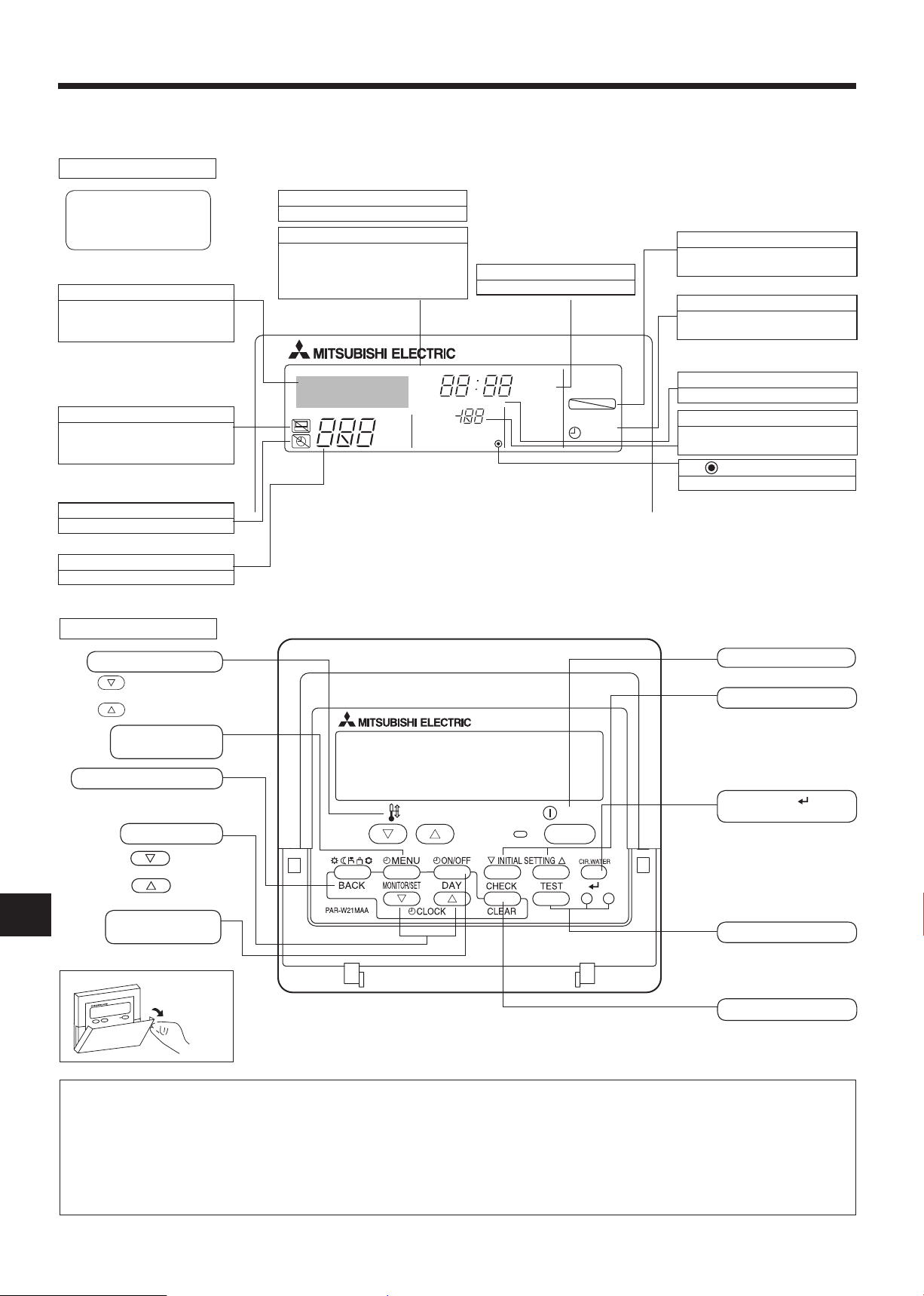
6.2 Parts name
■
Wired Remote-Controller
Display Section
For purposes of this explanation,
all parts of the display are shown.
During actual operation, only the
relevant items will be displayed.
Identies the current operation
Shows the operating mode, etc.
* Multi language display is sup
ported.
“Centrally Controlled” indicator
Indicates that operation of the remote controller has been prohibited
by a master controller.
“Timer is Off” indicator
Indicates that the timer is off.
Temperature Setting
Shows the target temperature.
Operation Section
Shows the current day of the week.
Time/Timer Display
Shows the current time, unless the
simple or Auto Off timer is set.
If the simple or Auto Off timer is set,
shows the time remaining.
ON/OFF indicator
Indicates if timer is set ON/OFF.
“Locked” indicator
Indicates that remote controller buttons have been locked.
Timer indicators
Day-of-Week
-
The indicator comes on if the corresponding timer is set.
Error indicator
Comes on when error occurs.
Temperature indicator
Shows the current water temperature.
(Power On indicator)
Indicates that the power is on.
Set Temperature buttons
Down
Up
Timer Menu button
(Monitor/Set button)
Mode button (Return button)
ON/OFF button
Setting change button
CIR. WATER button
(<Enter> button)
Set Time buttons
Back
Ahead
Timer On/Off button
(Set Day button)
Opening the
lid
Note:
● “PLEASE WAIT” message
This message is displayed for approximately 3 minutes when power is supplied to the FTC unit or when the unit is recovering from a power fail-
ure.
● “NOT AVAILABLE” message
Not available
TEST run function is not
available with this FTC unit.
Self check(Clear) button
This message is displayed if a button is pressed to operate a function that the FTC unit does not have, or a function that is not available due to
the setting.
15
BG
˚F˚C
˚C
TIME SUN
TIME SUN
˚C
˚C
TIME SUN
ON/OFF
TEMP.
˚C
˚C
ON/OFF
TEMP.
6. Remote controller operation
Function Selection of remote
controller
Standard Control Screens
OFF ON
Set Day/Time
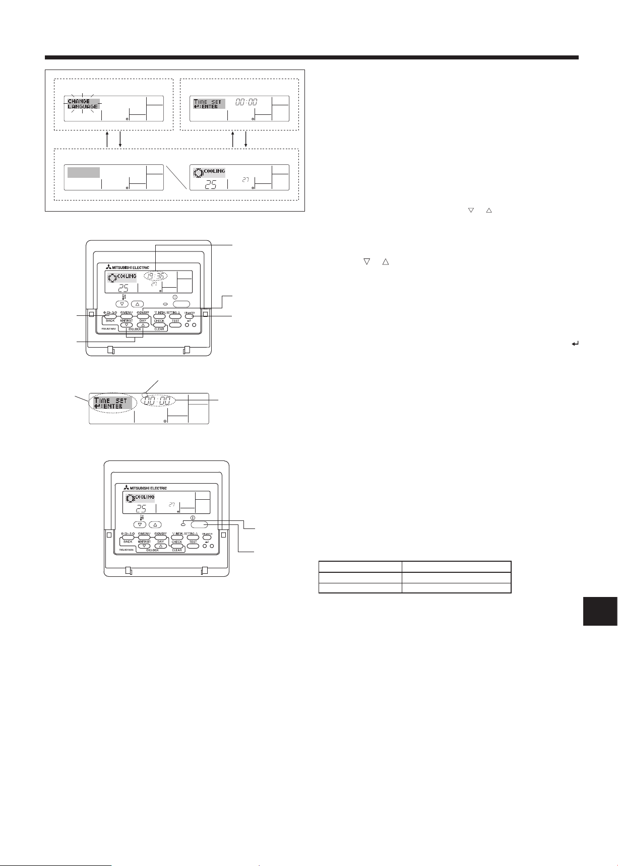
<Screen conguration>
For details on setting the language for the remote controller display, refer
to 6.6. Function Selection.
The initial language setting is English.
● Function Selection of remote controller:
● Set Day/Time:
● Standard Control Screens:
Set the functions and ranges available to the remote
controller (timer functions, operating restrictions, etc.)
Set the current day of the week or time.
View and set the air conditioning system’s operating
status
<How to change the screen>
A : Hold down both the Mode button 2 and the Timer On/Off button 9
for 2 seconds.
B : Press either of the Set Time buttons ( or ) 1.
c : Press the Mode button 2.
1
Day of the Week
& Time display
6.3 Setting the day of the week and time
1. Press the or Set Time button 1 to show display 2.
2. Press the Timer On/Off (Set Day) button 9 to set the day.
* Each press advances the day shown at 3 :
9
42
Sun→Mon→...→Fri→Sat.
3. Press the appropriate Set Time button 1 as necessary to set the time.
* As you hold the button down, the time (at 4) willincrementrstin
one-minute intervals, then in ten-minute intervals, and then in 1-hour
intervals.
1
4. After making the appropriate settings at Steps 2 and 3, press the
button 4 to lock in the values.
Note:
Day of the Week Setting
3
2
Time Setting
4
The day and time will not appear if clock use has been disabled at
Function Selection of remote controller.
6.4 Operation
Available items are different depending on your system.
(Refer to section 3.)
6.4.1 Switching
<To Start Operation>
■ Press the ON/OFF button 1.
• The ON lamp 1 and the display area come on.
1
1
Note:
When the unit restarts, the previous settings are recalled as follows.
Remote controller setting
Mode Last operation mode
Temperature setting Last set temperature
<To Stop Operation>
■
Press the ON/OFF button 1 again.
• The ON lamp 1 and the display area go dark.
Note:
Even if you press the ON/OFF button to restart the system while
turning down the operation, the outdoor unit will not start for about
3 minutes.
This is to prevent the internal components from being damaged.
6. Remote controller operation
˚C
˚C
TIME SUN
FUNCTION
ON/OFF
TEMP.
˚C
˚C
FUNCTION
˚C
˚C
FUNCTION
˚C
˚C
˚C
˚C
ON/OFF
TEMP.
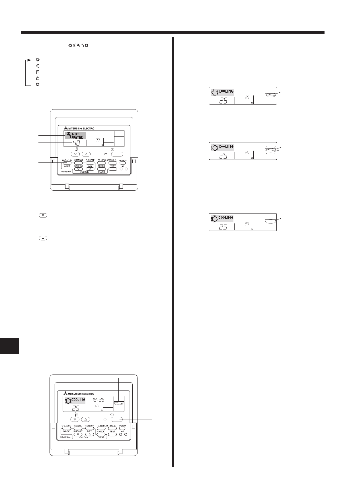
6.4.2. Mode select
Press operation mode ( ) button2 and select operation mode .
Heating mode (Space heating)
Heating ECO mode (
Space heating with weather compensation *1
)
Hot water mode (Sanitary hot water)
Anti freeze mode (
Heating to prevent water pipe from freezing
Cooling mode (Space cooling)
*1
Targetowtemp.variesaccordingtotheoutdoortemperature.(Refer
to 7. for setting.)
2
3
3
2
6.4.3. Temperature setting
► To decrease the target temperature:
Press button 3 to set the desired temperature.
The selected temperature is displayed 3.
<How to Lock the Buttons>
1. While holding down the CIR. WATER button 4, press and hold down
the ON/OFF button 1 for 2 seconds. The “Locked” indication appears
on the screen (at 1), indicating that the lock is now engaged.
* If locking has been disabled in Function Selection of remote control-
ler, the screen will display the “Not Available” message when you
)
press the buttons as described above.
1
• If you press a locked button, the “Locked” indication (at 1) will blink
on the display.
1
<How to Unlock the Buttons>
1. While holding down the CIR. WATER button 4, press and hold down
the ON/ OFF button 1 for 2 seconds—so that the “Locked” indication
disappears from the screen (at 1).
1
► To increase the target temperature:
Press button 3 to set the desired temperature.
The selected temperature is displayed 3.
Note: Heating ECO mode sets the set temperature depending on
the outdoor temperature.
6.5. Other Functions
6.5.1. Locking the Remote Controller Buttons (Operation function
limit)
■ If you wish, you can lock the remote controller buttons. You can use
the Function Selection of remote controller to select which type of lock
to use.
(For information about the lock type, refer to 6.6, item[2].)
Specically,youcanuseeitherofthefollowing2locktypes.
1 Lock All Buttons:
Locks all of the buttons on the remote controller.
2 Lock All Except ON/OFF:
Locks all buttons other than the ON/OFF button.
Note:
BG
The “Locked” indicator appears on the screen to indicate that buttons are currently locked.
Lock Indicator
1
16
1
4
6. Remote controller operation
ON/OFF
ERROR CODE
ON/OFF
˚C
˚C
ERROR CODE
ON/OFF
CALL:XXXX
XXX:XXX
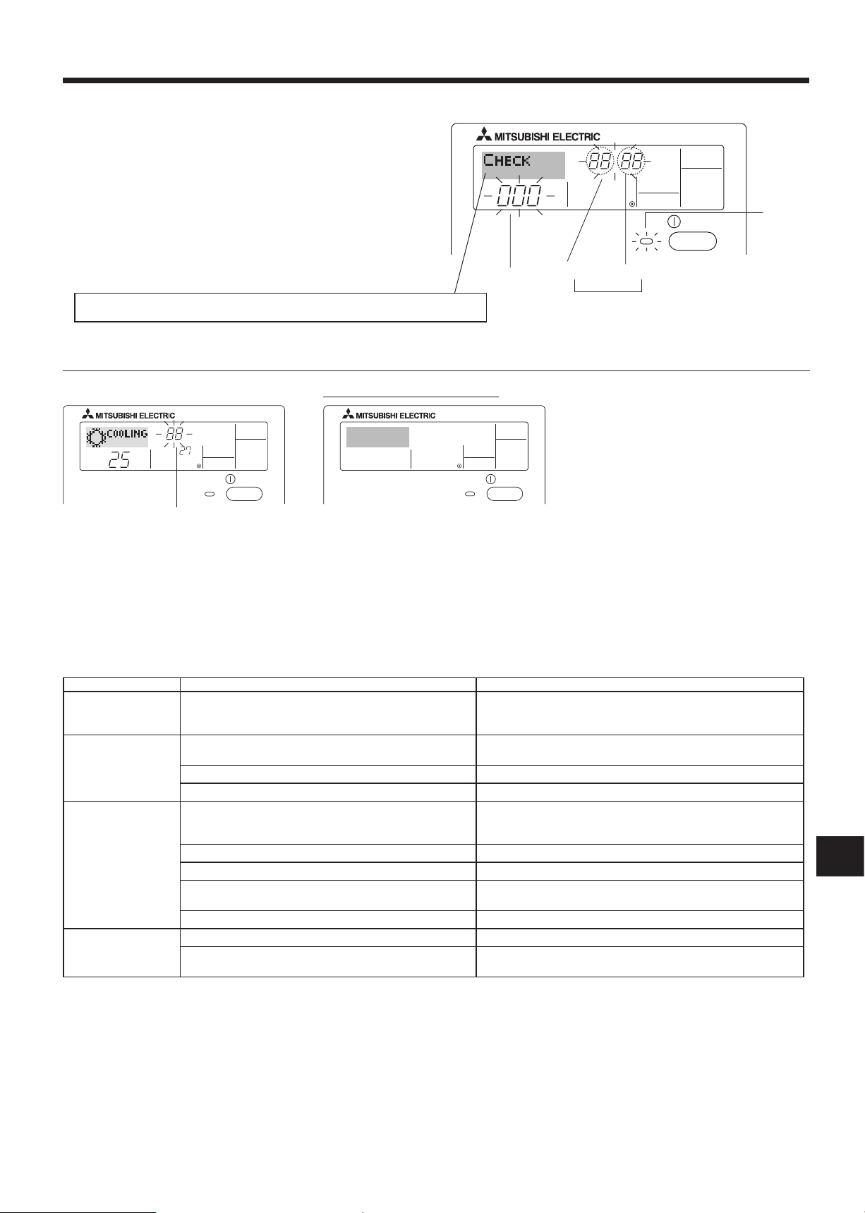
6.5.2. Error Codes indication
ON lamp
(Blinking)
Indoor Unit’s Refrigerant Address
If you have entered contact number to be called in the event of a problem, the screen displays this number.
(You can set this up under Function Selection of remote controller. For information, refer to 6.6.)
●
If the ON lamp and error code are both blinking: This means that the air conditioner is out of order and operation has been stopped (and cannot re-
Error Code Indoor Unit No.
Alternating Display
sume). Take note of the indicated unit number and error code, then switch off the power to the air conditioner and call your dealer or servicer.
When the Check button is pressed:
Error Code
●
If only the error code is blinking (while the ON lamp remains lit): Operation is continuing, but there may be a problem with the system. In this case,
you should note down the error code and then call your dealer or servicer for advice.
* If you have entered contact number to be called in the event of a problem, push the Check button to display it on the screen. (You can set this up
under Function Selection of remote controller. For information, refer to 6.6.)
6.6. Function Selection
Various remote controller functions are selectable in the remote controller function selection mode. Change setting when needed.
Item 1 Item 2 Item 3
1. Change language
(“CHANGE LAN
GUAGE”)
2. Function limit
(“FUNCTION SELEC
TION”)
3. Mode selection
(“MODE SELECTION”)
4. Display change
(“DISP MODE SET
TING”)
Language setting to display • Some European languages are selectable.
-
(1) Operation function limit setting (operation lock) (“LOCKING
-
FUNCTION”)
(2) Use of operation mode setting (“SELECT MODE”) • Setting the use or non-use of operation mode
(3) Temperature range limit setting (“LIMIT TEMP FUNCTION”) • Setting the temperature adjustable range (maximum, minimum)
(1) Remote controller main/sub setting (“CONTROLLER MAIN/
SUB”)
(2) Use of clock setting (“CLOCK”) • To select the use or non-use of clock function
(3) Timer function setting (“TIMER MODE”) • To select the timer type
(4) Contact number setting in case of fault (“CALL.”) • Contact number display in case of error
(5) Temperature offset setting(“TEMP OFFSET FUNCTION”) • To select the use or non-use of the water temperature offset funstion
(1) Temperature display °C/°F setting (“TEMP MODE °C/°F”) • To select the temperature unit (°C or °F) to display
-
(2) Water temperature display setting(“WATER TEMP. DISP.
SELECT”)
• To invalidate some functions.
• Selecting main or sub remote controller
* When 2 remote controllers are connected to 1 group, 1 controller
must be set to sub.
• To select the telephone number
• Toselecttheuseornon-useofthedisplayof“actualowwatertem
perature”
-
BG
17
 Loading...