

Mitsubishi Electric PAC-BH02KTY-E, PAC-BH02EHT-E, PAC-BH03EHT-E, PAC-BH01EHT-E Installation Manual
Air-Conditioners For Building Application
OUTDOOR UNIT
RELAY BOX
PAC-BH02KTY-E
BASE HEATER
PAC-BH01EHT-E, PAC-BH02EHT-E, PAC-BH03EHT-E
MANUEL D’INSTALLATION
Veuillez lire le manuel d’installation en entier avant d’installer ce climatiseur pour éviter tout accident et vous assurer d’une utilisation correcte.
GBDFEINLSV
INSTALLATIONSHANDBUCH
Zum sicheren und ordnungsgemäßen Gebrauch der Klimageräte das Installationshandbuch gründlich durchlesen.
MANUAL DE INSTALACIÓN
Para un uso seguro y correcto, lea detalladamente este manual de instalación antes de montar la unidad de aire acondicionado.
INSTALLATION MANUAL
For safe and correct use, please read this installation manual thoroughly before installing the air-conditioner unit.
MANUALE DI INSTALLAZIONE
Per un uso sicuro e corretto, leggere attentamente questo manuale di installazione prima di installare il condizionatore d’aria.
INSTALLATIEHANDLEIDING
Voor een veilig en juist gebruik moet u deze installatiehandleiding grondig doorlezen voordat u de airconditioner installeert.
RUHGPOSWRO CZ
РУКОВОДСТВО ПО УСТАНОВКЕ
Для осторожного и правильного использования прибора необходимо тщательно ознакомиться с данным руководством по установке
до выполнения установки кондиционера.
PŘÍRUČKA K INSTALACI
V zájmu bezpečného a správného používání si před instalací klimatizační jednotky důkladně pročtěte tuto příručku k instalaci.
NÁVOD NA INŠTALÁCIU
Pre bezpečné a správne použitie si pred inštalovaním klimatizačnej jednotky, prosím, starostlivo prečítajte tento návod na inštaláciu.
TELEPÍTÉSI KÉZIKÖNYV
A biztonságos és helyes használathoz, kérjük, olvassa el alaposan ezt a telepítési kézikönyvet, mielőtt telepítené a légkondicionáló egységet.
PODRĘCZNIK INSTALACJI
W celu bezpiecznego i poprawnego korzystania należy przed zainstalowaniem klimatyzatora dokładnie zapoznać się z niniejszym podręcznikiem instalacji.
INSTALLATIONSHANDBOK
Läs den här installationshandboken noga innan luftkonditioneringsenheten installeras, för säker och korrekt användning.
MANUAL CU INSTRUCŢIUNI DE INSTALARE
Pentru o utilizare corectă şi sigură, vă rugăm să citiţi cu atenţie acest manual înainte de a instala unitatea de aer condiţionat.
2
GB
Contents
1. Safety precautions ........................................................................ 2
1.1. Before installation and electric work .............................. 2
1.2. Before installation .......................................................... 2
1.3. Before installation (relocation) - electrical work ............. 2
1.4. Before starting the test run............................................. 3
2. Parts List....................................................................................... 4
3. Applicable models......................................................................... 6
4. Preparation for installation .............................................................7
5. Installation Procedures ..................................................................9
6. Heater Installation........................................................................ 10
7. Electrical Wiring...........................................................................33
8. Relay Box Installation ..................................................................37
9. Reassembly .................................................................................41
10.Confirmation of proper operation .................................................41
* For information not contained in this booklet, please refer to the Installation Manual of the outdoor unit.
• Consult your dealer for purchasing the Relay Box.
• The base heater is packaged separately from this product.
1. Safety precautions
1.1. Before installation and electric work
Symbols used in the text
Warning:
Describes precautions that should be observed to prevent danger of injury
or death to the user.
Caution:
Describes precautions that should be observed to prevent damage to the
unit.
Symbols used in the illustrations
: Indicates an action that must be avoided.
: Indicates that important instructions must be followed.
: Indicates a part which must be grounded.
: Beware of electric shock. (This symbol is displayed on the main unit label.)
<Color: yellow>
HIGH VOLTAGE WARNING:
• Control box houses high-voltage parts.
• When opening or closing the front panel of the control box, do not let it
come into contact with any of the internal components.
• Before inspecting the inside of the control box, turn off the power, keep
the unit off for at least 10 minutes, and confirm that the voltage between
FT-P and FT-N on INV Board has dropped to DC20V or less.
(It takes about 10 minutes to discharge electricity after the power supply
is turned off.)
Warning:
• Ask the dealer or an authorized technician to install the air conditioner.
- Improper installation b y the user may result in water leakage, electric shock,
or fire.
• This appliance is not intended for use by persons (including children)
with reduced physical, sensory or mental capabilities, or lack of experience and knowledge, unless they have been given supervision or
instruction concerning use of the appliance by a person responsible for
their safety.
• Use the specified cables for wiring. Make the connections securely so
that the outside force of the cable is not applied to the terminals.
- Inadequate connection and fastening may generate heat and cause a fire.
• Always use Relay Box and other accessories specified by Mitsubishi
Electric.
- Ask an authorized tech nician to install the accessories. Improper inst allation
by the user may result in water leakage, electric shock, or fire.
• Never repair the unit. If the air conditioner must be repaired, consult the
dealer.
- If the unit is repaired improperly, water leakage, electric shock, or fire may
result.
• If the supply cord is damaged, it must be replaced by the manufacturer,
its service agent or similarly qualified persons in order to avoid a hazard.
• To reduce the risk of electric shock, do not install the unit when it is
raining.
• Never attempt to repair the unit without the proper qualifications. If the
air conditioner must be repaired consult the dealer, contractor or qualified Refrigeration Engineer.
- If the unit is repaired improperly, water leakage, electric shock, or fire may
result.
• Have all electric work done by a licensed electrician according to the
“Electric Facility Engineering Standard”, the “Wire Regulations in each
area” and the instructions given in this manual and always use a dedicated power supply.
- If the power source capacity is inadequat e or electric work is performed
improperly, electric shock and fire may result.
• Securely install the outdoor unit terminal cover (panel).
- If the terminal cover (panel ) i s not installed properly, dust or water may
enter the outdoor unit and fire or electric shock may result.
• When moving and reinstalling the air conditioner, consult the dealer or
an authorized technician.
- If the air conditioner is installe d improperly, water leakage, electric shock, or
fire may result.
• Do not reconstruct or change the settings of the protection devices.
- If the pressure switch, thermal switch, fuse, or other protecti on device is
shorted or operated forcibly, or parts other than those specified by Mitsubishi Electric are used, fire or explosion may result.
• To dispose of this product, consult your dealer.
• The installer and system specialist shall secure safety against leakage
according to local regulation or standards.
- Choose the appropriate wire size and the switch cap acities for the main
power supply described in this manual if local regulations are not available.
• Children should be supervised to ensure that they do not play with the
appliance.
1.2.
Before installation
Caution:
• Do not use the air conditioner in special environments.
- Oil, steam, sulfuric smoke, etc. ca n significantly reduce the performance of
the air conditioner or damage its parts.
• When installing the unit in a hospital, communication station, or similar
place, provide sufficient protection against noise.
- Inverter equipment, privat e power g enera tor, high-frequency medical equip-
ment, or radio communication equipment may cause the air conditioner to
operate erroneously, or fail to operate. On the other hand, the air conditioner may affect such equipment by creating noise that disturbs medical
treatment or image broadcasting.
• To reduce the risk of injury, wear protective gear when working on the
controller.
1.3. Before installation (relocation) -
electrical work
Caution:
• Ground the unit.
- Do not connect the ground wire to gas or water pipes, lightning rods, or tel-
ephone ground lines. Improper grounding may result in electric shock.
• Install the power cable so that tension is not applied to the cable.
- Tension may cause the cable to break and generate heat and cause a fire.
• Install a leak circuit breaker, as required.
- If a leak circuit breaker is not installed, elect ric shock may result.
• Use power line cables of sufficient current carrying capacity and rating.
- Cables that are too small may leak, generate heat, and cause a fire.
• Use only a circuit breaker and fuse of the specified capacity.
- A fuse or circuit breaker of a larger capacity, or the use of a substitute
simple steel or copper wire may result in a general unit failure or fire.
• Stop the operation and turn off the power before cleaning.
• Do not wash the air conditio ner units.
- Washing them may cause an electric shock.
Before installing the unit, make sure you read all the “Safety
precautions”.
The “Safety precautions” provide very important points
regarding safety. Make sure you follow them.
Warning:
Carefully read the labels affixed to the main unit.

3
GB
• Be very careful about transporting the product.
- One person should not carry the product. Its weight is in excess of 20 kg
[45 LBS].
- Some products u se PP bands for p ackaging. Do not use any PP bands as a
means of transportation. It is dangerous.
• Safely dispose of the packing materials.
- Packing materials, such as nails and other metal or wooden parts, may
cause stabs or other injuries.
- Tear apart and throw away plastic packaging bags so that children will not
play with them. If children play with a plastic bag which has not been torn
apart, they face the risk of suffocation.
• Never connect in reverse phases.
• Install the power cable so that tension is not applied to the cable.
• Do not wash the air conditioner units.
1.4. Before starting the test run
Caution:
• Turn on the power at least 12 hours before starting operation.
- Starting operation immediately after turning on the main power switch can
result in irreversible damage to internal parts. Keep the power switch turned
on during the operational season. Make sure of the phase order of power
supply and voltage between each phase.
• Do not touch the switches with wet fingers.
- Touching a switch with wet fingers can result in an electric shock.
• Do not touch the refrigerant pipes during and immediately after operation.
- During and immediately after operation, the refrigerant pipes may be hot or
cold, depending on the condition of the refrigerant flowing through the
refrigerant piping, compressor, and other refrigeran t cycle parts. Your hands
may suffer burns or frostbite if you touch the refrigerant pipes.
• Do not operate the air conditioner with the panels and guards removed.
- Rotating, hot, or high-voltage parts can cause injuries.
• Do not turn off the power immediately after stopping operation.
- Always wait at least 5 minutes before turning off the power. Otherwise,
drainage water leakage or mechanical failure of sensitive parts may occur.
4
GB
2. Parts List
<PAC-BH02KTY-E>
This kit contains the following parts.
<PAC-BH01EHT-E>
This kit contains the following parts.
-
-
* Use proper mounting brackets according to the outdoor unit model.
Refer to table “Heater mounting bracket list” in section 4. “Preperation for ins tallation” on page 7.
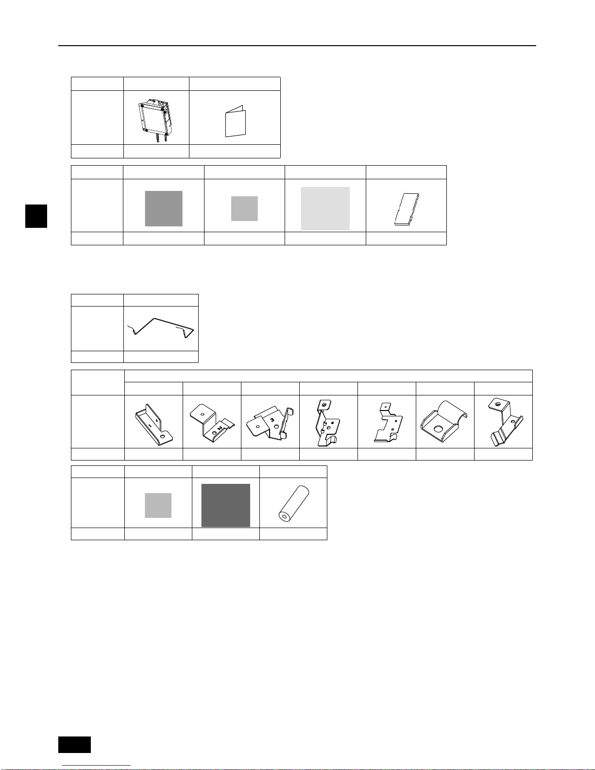
Parts name Relay Box Installation Manual
Shape
Qty. 1 1
Parts name A Cable strap B M5 screw C Cable tie (black) D Wire seal
Shape
Qty. 1 3 4 1
Parts name Base Heater
Shape
Qty. 1
Parts name
* Heater mounting brackets
1234567
Shape
Qty.1111111
Parts name M5 screw Cable tie (blue) Pipe cover
Shape
Qty. 5 (2 for spare) 5 1
5
GB
<PAC-BH02EHT-E>
This kit contains the following parts.
-
* Use proper mounting brackets according to the outdoor unit model.
Refer to table “Heater mounting bracket list” in section 4. “Preperation for ins tallation” on page 8.
<PAC-BH03EHT-E>
This kit contains the following parts.
-
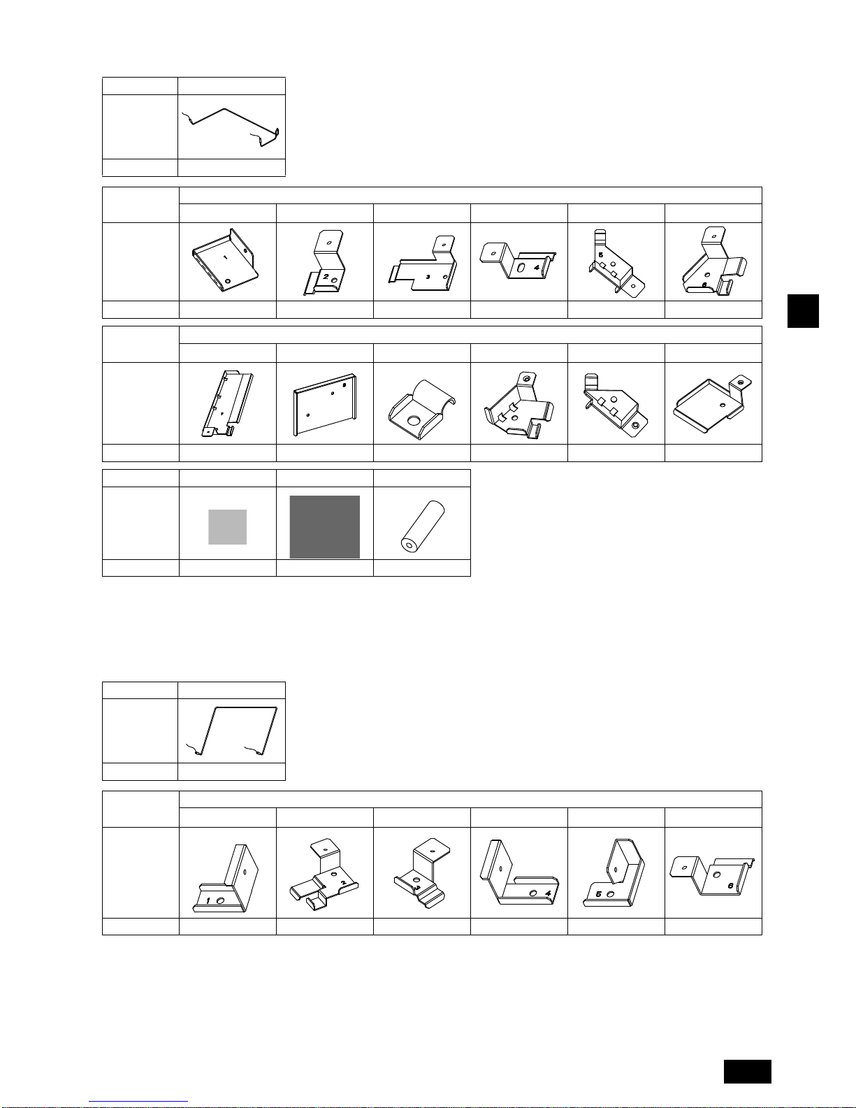
Parts name Base Heater
Shape
Qty. 1
Parts name
* Heater mounting brackets
123456
Shape
Qty.111111
Parts name
* Heater mounting brackets
7890ab
Shape
Qty.113111
Parts name M5 screw Cable tie (blue) Pipe cover
Shape
Qty. 6 5 1
Parts name Base Heater
Shape
Qty. 2
Parts name
* Heater mounting brackets
123456
Shape
Qty.112111

6
GB
-
* Use proper mounting brackets according to the outdoor unit model.
Refer to table “Heater mounting bracket list” in section 4. “Preperation for ins tallation” on page 9.
3. Applicable models
Parts name
* Heater mounting brackets Wiring fixing brackets
7890
Shape
Qty.1311
Parts name Cable strap M5 screw Cable tie (blue)
Shape
Qty . 2 10 (2 for spare) 5
Type
Unit model Target sales area Applicable models S module L module XL module
PAC-BH02KTY-E
Europe and
other countries
PUHY-P○YHM-A 200, 250, 300 350, 400, 450 –
PUHY-EP○YHM-A 200 250, 300 –
PUHY-P○YJM-A 200, 250, 300 350, 400 450
PUHY-EP○YJM-A 200 250 300
PUHY-HP○YHM-A 200, 250 – –
PUHY-RP○YJM-A 200, 250, 300, 350 – –
PURY-P○YHM-A 200, 250, 300 350, 400 –
PURY-EP○YHM-A 200 250, 300 –
PURY-P○YJM-A 200, 250, 300 350, 400 450
PURY-EP○YJM-A 200 250, 300 350
PURY-RP○YJM-A – 200, 250, 300 –
7
GB
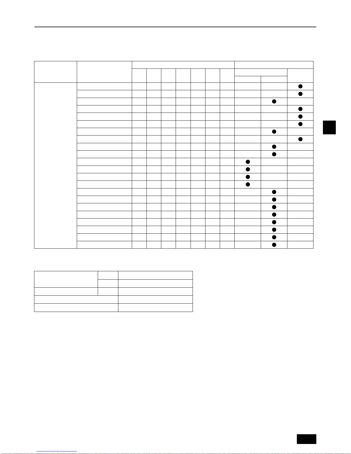
4. Preparation for installation
<PAC-BH01EHT-E>
• This base heater and the Relay Box must be installed by a dealer or certified technician.
• Refer to the table below for the required mounting brackets for the outdoor unit on which the base heater will be installed.
Heater mounting bracket list
* The numbers in the table indicate the number of parts to be used.
Specifications of the outdoor unit base heater
• The following to ols are required to install the base heater. These are field-supplied.
Phillips screwdriver (magnetic tip): Use to remove or install panels.
Phillips screwdriver (Minimum 40 cm, magnetic tip): Use to install or uninstall the mounting brackets, and to screw or unscrew
the screws on the accumulator.
Ratchet, spanner: Use to fix the mounting brackets to the screw holes on the accumulator. Use when the screws on the
accumulator are hard to remove.
Threaded rod (Minimum 60 cm, M5): Use to install the mounting brackets to the base.
Nippers: Use to cut cable ties.
Tester: Use to check the base heater for proper operation.
Gloves: Use to keep your hands out of direct contact with the heat exchanger fins, hot section, etc.
Helmet or cap: Use to keep your head protected when you bump your head against the outdoor unit fan motor.
Head light: Use when it is too dark to see the bracket mounting area.
• Check that the main power on the outdoor unit is turned off.
• Base heater installation requires many screws to be unscrewed. Do not lose these screws.
• Thoroughly remove the dust from the base of the unit.
Target sales area Applicable models
Heater mounting bracket Accumulator type
1234567
Large
Small
With Oil tank Non Oil tank
Europe and
other countries
PUHY-P200YHM-A 1 1 1 1 - 1 - - PUHY-P250YHM-A 1 1 1 1 - 1 - - PUHY-P300YHM-A 1 1 1 - 1 1 - - PUHY-EP200YHM-A 1 1 1 1 - 1 - - PUHY-P200YJM-A 1 1 1 1 - 1 - - PUHY-P250YJM-A 1 1 1 1 - 1 - - PUHY-P300YJM-A 1 1 1 - 1 1 - - PUHY-EP200YJM-A 1 1 1 1 - 1 - - PUHY-HP200YHM-A 1 1 1 - 1 1 - - PUHY-HP250YHM-A 1 1 1 - 1 1 - - PUHY-RP200YJM-A 1 - 1 - 1 1 1 - PUHY-RP250YJM-A 1 - 1 - 1 1 1 - PUHY-RP300YJM-A 1 - 1 - 1 1 1 - PUHY-RP350YJM-A 1 - 1 - 1 1 1 - PURY-P200YHM-A 1 1 1 - 1 1 - - PURY-P250YHM-A 1 1 1 - 1 1 - - PURY-P300YHM-A 1 1 1 - 1 1 - - PURY-EP200YHM-A 1 1 1 - 1 1 - - PURY-P200YJM-A 1 1 1 - 1 1 - - PURY-P250YJM-A 1 1 1 - 1 1 - - PURY-P300YJM-A 1 1 1 - 1 1 - - PURY-EP200YJM-A 1 1 1 - 1 1 - - -
Output
[W] 181 (220)/198 (230)/216 (240)
[W/m] 116 (220)/127 (230)/139 (240)
Power supply voltage [V] 220, 230, 240
Heater length [mm (inch)] 1554 (62.2)
Heater diameter [mm (inch)] ø8 (ø0.32)

8
GB
<PAC-BH02EHT-E>
• This base heater and the Relay Box must be installed by a dealer or certified technician.
• Refer to the table below for the required mounting brackets for the outdoor unit on which the base heater will be installed.
Heater mounting bracket list
* The numbers in the table indicate the number of parts to be used.
Specifications of the outdoor unit base heater
• The following to ols are required to install the base heater. These are field-supplied.
Phillips screwdriver (magnetic tip): Use to remove or install panels.
Phillips screwdriver (Minimum 40 cm, magnetic tip): Use to install or uninstall the mounting brackets, and to screw or unscrew
the screws on the accumulator.
Ratchet, spanner: Use to fix the mounting brackets to the screw holes on the accumulator. Use when the screws on the
accumulator are hard to remove.
Threaded rod (Minimum 60 cm, M5): Use to install the mounting brackets to the base.
Nippers: Use to cut cable ties.
Tester: Use to check the base heater for proper operation.
Gloves: Use to keep your hands out of direct contact with the heat exchanger fins, hot section, etc.
Helmet or cap: Use to keep your head protected when you bump your head against the outdoor unit fan motor.
Head light: Use when it is too dark to see the bracket mounting area.
• Check that the main power on the outdoor unit is turned off.
• Base heater installation requires many screws to be unscrewed. Do not lose these screws.
• Thoroughly remove the dust from the base of the unit.
Target
sales
area
Applicable models
Heater mounting bracket Accumulator type
1234567890ab
Vertical
installation
Horizontal
installation
Europe
and
other
countries
PUHY -P350YHM-A 1 1 - 1 - - 1 1 3 - - - PUHY -P400YHM-A 1 1 - 1 - - 1 1 3 - - - PUHY -P450YHM-A 1 1 - 1 - - 1 1 3 - - - PUHY-EP250YHM-A 1 1 - 1 - - 1 1 3 - - - PUHY-EP300YHM-A 1 1 - 1 - - 1 1 3 - - - PUHY-P350YJM-A 1 1 - 1 - - 1 1 3 - - - PUHY-P400YJM-A 1 1 - 1 - - 1 1 3 - - - PUHY-EP250YJM-A 1 1 - 1 - - 1 1 3 - - - PURY-P350YHM-A 1 - 1 1 - - 1 1 3 - - - PURY-P400YHM-A 1 - 1 1 - - 1 1 3 - - - PURY-EP250YHM-A 1 - 1 1 - - 1 1 3 - - - PURY-EP300YHM-A 1 - 1 1 - - 1 1 3 - - - PURY-P350YJM-A 1 - 1 1 - - 1 1 3 - - - PURY-P400YJM-A 1 - 1 1 - - 1 1 3 - - - PURY-EP250YJM-A 1 - 1 1 - - 1 1 3 - - - PURY-EP300YJM-A 1 - 1 1 - - 1 1 3 - - - PURY-RP200YJM-A 1 - 1 - - - - - 1 1 1 1 PURY-RP250YJM-A 1 - 1 - - - - - 1 1 1 1 PURY-RP300YJM-A 1 - 1 - - - - - 1 1 1 1 -
Output
[W] 181 (220)/198 (230)/216 (240)
[W/m] 89 (220)/98 (230)/107 (240)
Power supply voltage [V] 220, 230, 240
Heater length [mm (inch)] 2024 (81.0)
Heater diameter [mm (inch)] ø8 (ø0.32)
9
GB
<PAC-BH03EHT-E>
• This base heater and the Relay Box must be installed by a dealer or certified technician.
• Refer to the table below for the required mounting brackets for the outdoor unit on which the base heater will be installed.
Heater mounting bracket list
* The numbers in the table indicate the number of parts to be used.
Specifications of the outdoor unit base heater
• The following to ols are required to install the base heater. These are field-supplied.
Phillips screwdriver (magnetic tip): Use to remove or install panels.
Phillips screwdriver (Minimum 40 cm, magnetic tip): Use to install or uninstall the mounting brackets, and to screw or unscrew
the screws on the accumulator.
Ratchet, spanner: Use to fix the mounting brackets to the screw holes on the accumulator. Use when the screws on the
accumulator are hard to remove.
Threaded rod (Minimum 60 cm, M5): Use to install the mounting brackets to the base.
Nippers: Use to cut cable ties.
Tester: Use to check the base heater for proper operation.
Gloves: Use to keep your hands out of direct contact with the heat exchanger fins, hot section, etc.
Helmet or cap: Use to keep your head protected when you bump your head against the outdoor unit fan motor.
Head light: Use when it is too dark to see the bracket mounting area.
• Check that the main power on the outdoor unit is turned off.
• Base heater installation requires many screws to be unscrewed. Do not lose these screws.
• Thoroughly remove the dust from the base of the unit.
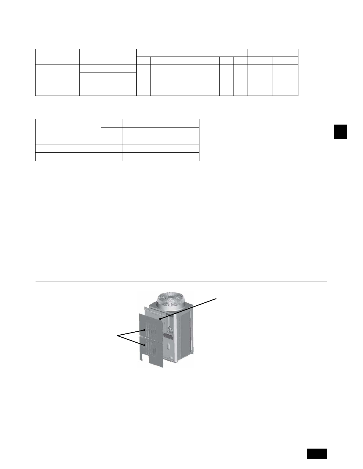
5. Installation Procedures
(1) Removing the panels and the control box
Target sales area Applicable models
Heater mounting bracket Wiring fixing bracket
12345678 9 0
Europe and
other countries
PUHY-P450YJM-A
11211113 1 1
PUHY-EP300YJM-A
PURY-P450YJM-A
PURY-EP350YJM-A
Output
[W] 362 (220)/396 (230)/432 (240)
[W/m] 102 (220)/111 (230)/121 (240)
Power supply voltage [V] 220, 230, 240
Heater length [mm (inch)] 1783 × 2 (71.3 × 2)
Heater diameter [mm (inch)] ø8 (ø0.32)
1. Remove the top and
bottom access panels.
2. Removing the control box
1 Remove the cover.
2 Unplug the cable connectors.
3 Disconnect the compressor wiring from
the terminal block on the compressor.
4 Unplug the power wire from the power
supply terminal block.
5 Remove the control box.
6 Loosen the fan motor power wire.
10
GB
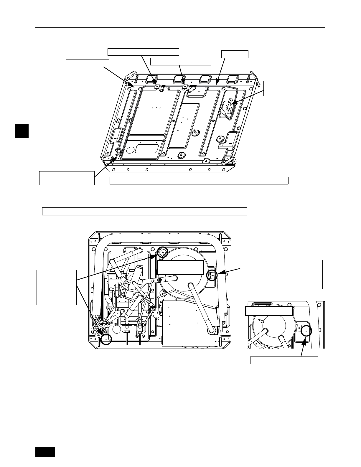
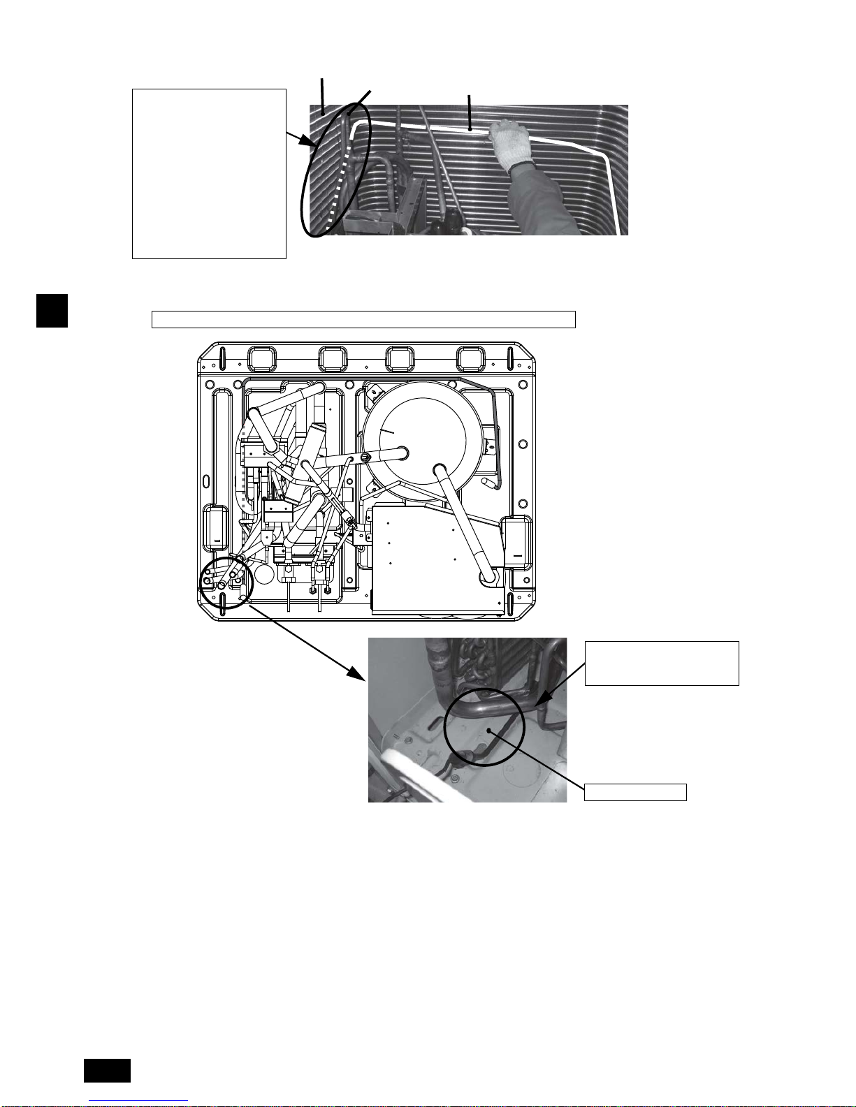
6. Heater Installation
<PAC-BH01EHT-E>
Run the base heater along the groove on the unit base.
● Install the base heater inside the unit by following the procedures (6)-1 through (6)-3 below.
(6)-1 Unscrew the screws as shown in the figure below.
Caution: To reduce the risk of injury, wear protective gear when installing the base heater.
Groove on the base
Heater mounting bracket 2 or 7
Base heater
Heater mounting bracket
1 , 6
Note: The figure shows a simplified view of the unit base without the components on it.
Heater mounting bracket
4 or 5
Heater mounting bracket 3
Unscrew each
screw that is for
the base leg and
accumulator
installation.
(1 pc. each)
For the LARGE Accumulator, remove
the screw (1 pc.).
For the SMALL Accumulator (see the
figure below), do not remove any screw.
Base heater installation position
SMALL Accumulat or
LARGE Accumulator
Non Oil tank
11
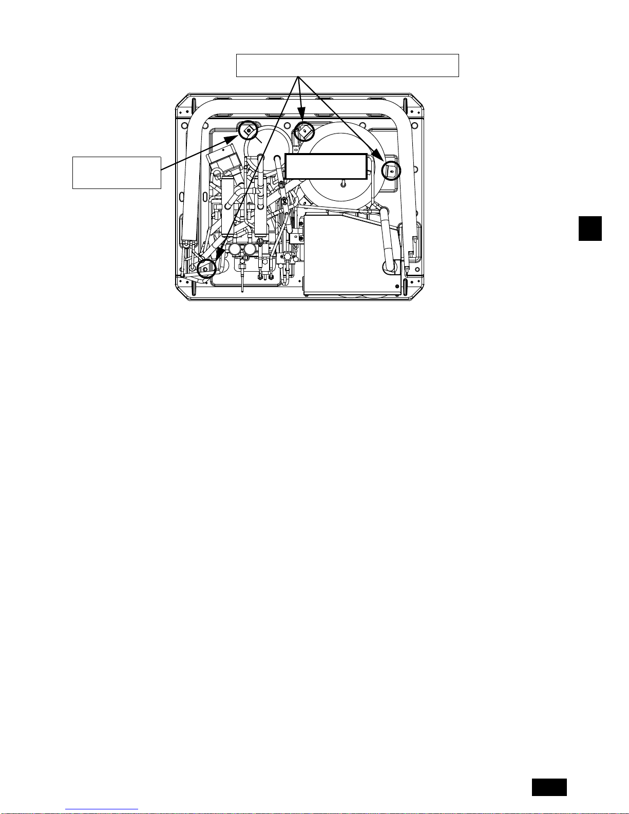
GB
Unscrew a screw that
is for the Oil tank
installation.
LARGE Accumulator
With Oil tank
Unscrew each screw that is for the base leg and accumulator
installation. (1 pc. each)
12
GB
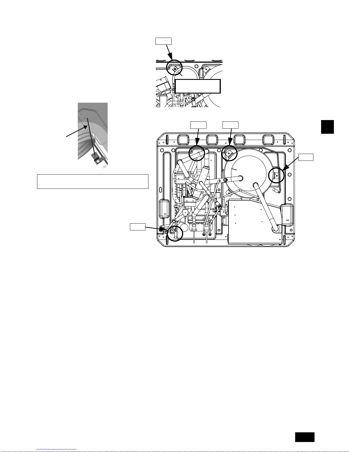
(6)-2 Attac
h the base heater to the outdoor unit base.
Insert the left side of the base
heater (longer ends) between
the heat exchanger and the
refrigerant pipes, and bring the
base heater down to the
outdoor unit base.
Route the wiring on the left side
of the base heater under the
refrigerant pipes to the front of
the unit base. Then, run the tip
of the base heater under the
refrigerant pipes to the front of
the unit base.
Base heater
After the base heater is inserted (before the heater mounting brackets are installed)
Groove on the base
Run the base heater along the
groove on the base to keep it
out of contact with other pipes.
Heat exchanger
Refrigerant pipe
13
GB
(6)-3 Install the heater mounting brackets.
* For easier installation of the heater mounting brackets 2 through 5 and 7, use a threaded rod (M5).
Follow the steps below.
Step 1: Install the heater mounting
bracket
4 or 5.
Step 2: Install the heater mounting
bracket
3.
Step 3: Install the heater mounting
bracket
2 or 7.
Step 4: Install the heater mounting
brackets
1 and 6.
<Usage example of the Threaded rod (M5)>
* Remove the Threaded rod after the use is completed.
Step 3
Step 2
Step 1
Step 4
Threaded rod (M5)
LARGE Accumulator
With Oil tank
Step 3
14
GB
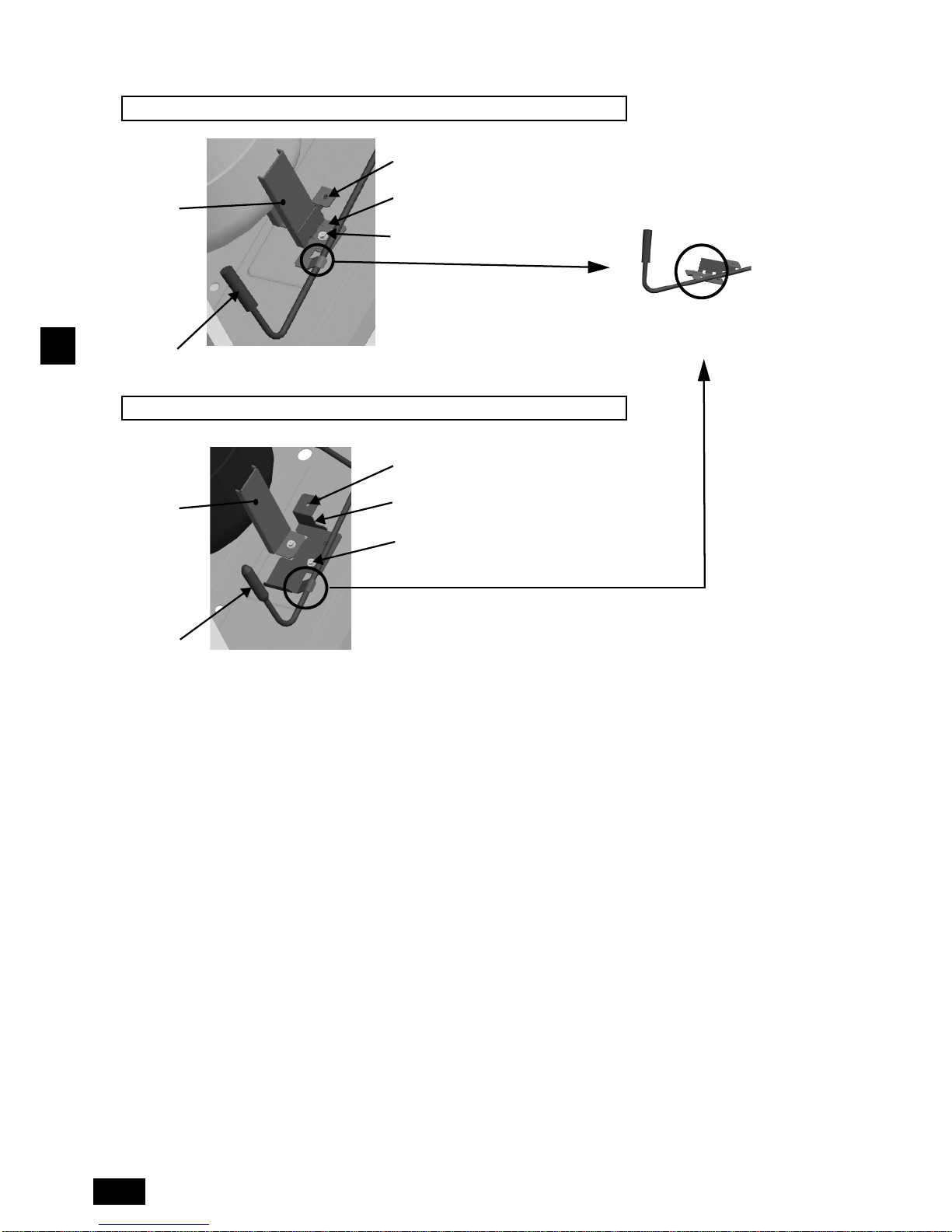
Step 1. Install the heater mounting bracket 4 or 5.
* When using the heater mounting bracket 4
or 5, refer to ”Applicable models” on page 6 and “Heater mounting bracket list” on page 7.
Base heater
For the LARGE Accumulator, install heater mounting bracket 4 as shown in the figure below.
For the SMALL Accumulator, install heater mounting bracket 5 as shown in the figure below.
Base heater
Accumulator
support leg
Thread part for the
Threaded rod (M5)
Heater mounting
bracket
4
Tilt the heater mounting bracket 4 or 5 a little to
attach it to the heater, slide it to the Accumulator
support leg, and secure them together.
Thread part for the
Threaded rod (M5)
Heater mounting
bracket
5
Use the supplied screw (M5).
Use the screw (M5) that
was removed.
Accumulator
support leg
 Loading...