

Page 1
AIR CONDITIONERS CITY MULTI
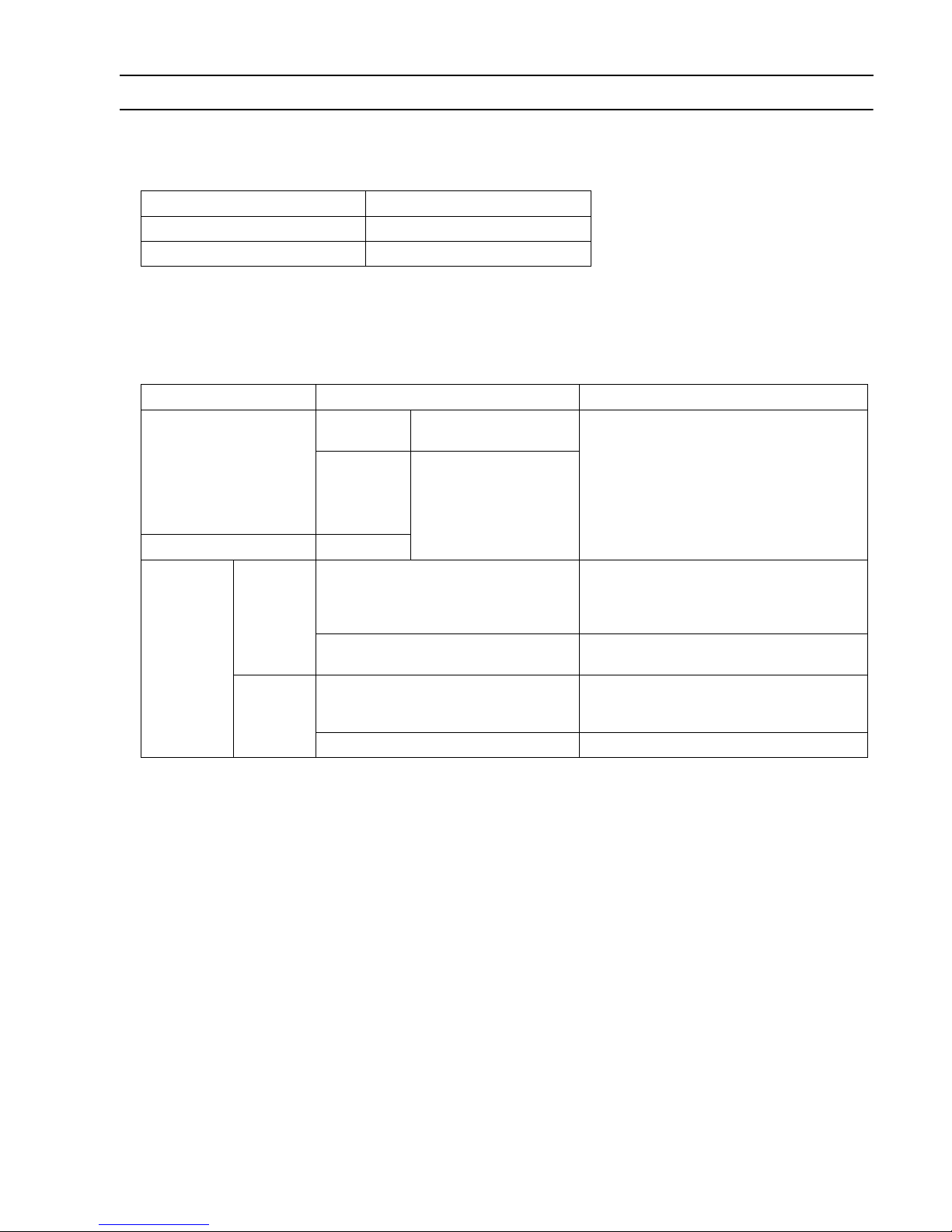
Models
PQHY-P72, P96TGMU-A
PQRY-P72, P96TGMU-A
CMB-P104, P105, P106, P108, P1010, P1013, P1016NU-G
CMB-P108, P1010, P1013, P1016NU-GA
CMB-P104, P108NU-GB
Service Handbook
Page 2
Safety Precautions
Before installing the unit, thoroughly read the following safety precautions.
Observe these safety precautions for your safety.
WARNING
This symbol is intended to alert the user to the presence of important instructions that must be followed to avoid
the risk of serious injury or death.
CAUTION
This symbol is intended to alert the user to the presence of important instructions that must be followed to avoid
the risk of serious injury or damage to the unit.
After reading this manual, give it to the user to retain for future reference.
Keep this manual for easy reference. When the unit is moved or repaired, give this manual to those who provide these ser-
vices.
When the user changes, make sure that the new user receives this manual.
WARNING
Ask your dealer or a qualified technician to install the
unit.
Improper installation by the user may result in water leakage, electric shock, smoke, and/or fire.
Properly install the unit on a surface that can withstand
the weight of the unit.
Unit installed on an unstable surface may fall and cause injury.
Only use specified cables. Securely connect each cable so that the terminals do not carry the weight of the
cable.
Improperly connected or fixed cables may produce heat
and start a fire.
Take appropriate safety measures against strong
winds and earthquakes to prevent the unit from falling.
If the unit is not installed properly, the unit may fall and
cause serious injury to the person or damage to the unit.
Do not make any modifications or alterations to the
unit. Consult your dealer for repair.
Improper repair may result in water leakage, electric shock,
smoke, and/or fire.
In the event of a refrigerant leak, thoroughly ventilate
the room.
If refrigerant gas leaks and comes in contact with an open
flame, poisonous gases will be produced.
When installing the All-Fresh type units, take it into
consideration that the outside air may be discharged
directly into the room when the thermo is turned off.
Direct exposure to outdoor air may have an adverse effect
on health. It may also result in food spoilage.
Properly install the unit according to the instructions in
the installation manual.
Improper installation may result in water leakage, electric
shock, smoke, and/or fire.
Have all electrical work performed by an authorized
electrician according to the local regulations and instructions in this manual, and a dedicated circuit must
be used.
Insufficient capacity of the power supply circuit or improper
installation may result in malfunctions of the unit, electric
shock, smoke, and/or fire.
Page 3
WARNING
Securely attach the terminal block cover (panel) to the
unit.
If the terminal block cover (panel) is not installed properly,
dust and/or water may infiltrate and pose a risk of electric
shock, smoke, and/or fire.
Only use the type of refrigerant that is indicated on the
unit when installing or reinstalling the unit.
Infiltration of any other type of refrigerant or air into the unit
may adversely affect the refrigerant cycle and may cause
the pipes to burst or explode.
When installing the unit in a small room, exercise caution and take measures against leaked refrigerant
reaching the limiting concentration.
Consult your dealer with any questions regarding limiting
concentrations and for precautionary measures before installing the unit. Leaked refrigerant gas exceeding the limiting concentration causes oxygen deficiency.
Consult your dealer or a specialist when moving or reinstalling the unit.
Improper installation may result in water leakage, electric
shock, and/or fire.
After completing the service work, check for a gas leak.
If leaked refrigerant is exposed to a heat source, such as a
fan heater, stove, or electric grill, poisonous gases may be
produced.
Do not try to defeat the safety features of the unit.
Forced operation of the pressure switch or the temperature
switch by defeating the safety features of these devices, or
the use of accessories other than the ones that are recommended by MITSUBISHI may result in smoke, fire, and/or
explosion.
Only use accessories recommended by MITSUBISHI.
Ask a qualified technician to install the unit. Improper installation by the user may result in water leakage, electric
shock, smoke, and/or fire.
Page 4
Precautions for handling units for use with R410A
CAUTION
Do not use the existing refrigerant piping.
A large amount of chlorine that may be contained in the re-
sidual refrigerant and refrigerating machine oil in the existing piping may cause the refrigerating machine oil in the
new unit to deteriorate.
R410A is a high-pressure refrigerant and can cause the
existing pipes to burst.
Use refrigerant pipes made of phosphorus deoxidized
copper. Keep the inner and outer surfaces of the pipes
clean and free of such contaminants as sulfur, oxides,
dust, dirt, shaving particles, oil, and water.
These types of contaminants inside the refrigerant pipes
may cause the refrigerant oil to deteriorate.
Store the pipes to be installed indoors, and keep both
ends of the pipes sealed until immediately before brazing. (Keep elbows and other joints wrapped in plastic.)
Infiltration of dust, dirt, or water into the refrigerant system
may cause the refrigerating machine oil to deteriorate or
cause the unit to malfunction.
Use a small amount of ester oil, ether oil, or alkylbenzene to coat flares and flanges.
Infiltration of a large amount of mineral oil may cause the refrigerating machine oil to deteriorate.
Charge liquid refrigerant (as opposed to gaseous refrigerant) into the system.
If gaseous refrigerant is charged into the system, the composition of the refrigerant in the cylinder will change and
may result in performance loss.
Use a vacuum pump with a reverse-flow check valve.
If a vacuum pump that is not equipped with a reverse-flow
check valve is used, the vacuum pump oil may flow into the
refrigerant cycle and cause the refrigerating machine oil to
deteriorate.
Prepare tools for exclusive use with R410A. Do not use
the following tools if they have been used with the conventional refrigerant (gauge manifold, charging hose,
gas leak detector, reverse-flow check valve, refrigerant
charge base, vacuum gauge, and refrigerant recovery
equipment.).
If the refrigerant or the refrigerating machine oil left on
these tools are mixed in with R410A, it may cause the refrigerating machine oil to deteriorate.
Infiltration of water may cause the refrigerating machine oil
to deteriorate.
Gas leak detectors for conventional refrigerants will not de-
tect an R410A leak because R410A is free of chlorine.
Do not use a charging cylinder.
If a charging cylinder is used, the composition of the refrigerant will change, and the unit may experience power loss.
Exercise special care when handling the tools for use
with R410A.
Infiltration of dust, dirt, or water into the refrigerant system
may cause the refrigerating machine oil to deteriorate.
Only use refrigerant R410A.
The use of other types of refrigerant that contain chlorine
(i.e. R22) may cause the refrigerating machine oil to deteriorate.
Page 5
Before installing the unit
WARNING
Do not install the unit where a gas leak may occur.
If gaseous refrigerant leaks and piles up around the unit, it
may be ignited.
Do not use the unit to keep food items, animals, plants,
artifacts, or for other special purposes.
The unit is not designed to preserve food products.
Do not use the unit in an unusual environment.
Do not install the unit where a large amount of oil or steam
is present or where acidic or alkaline solutions or chemical
sprays are used frequently. Doing so may lead to a remarkable drop in performance, electric shock, malfunctions,
smoke, and/or fire.
The presence of organic solvents or corrosive gas (i.e. am-
monia, sulfur compounds, and acid) may cause gas leakage or water leakage.
When installing the unit in a hospital, take appropriate
measures to reduce noise interference.
High-frequency medical equipment may interfere with the
normal operation of the air conditioner or vice versa.
Do not install the unit on or over things that cannot get
wet.
When the humidity level exceeds 80% or if the drainage
system is clogged, the indoor unit may drip water. Drain water is also discharged from the outdoor unit. Install a centralized drainage system if necessary.
Page 6
Before installing the unit (moving and reinstalling the unit) and performing electrical
work
WARNING
When installing or relocating the unit, make sure that
no substance other than the specified refrigerant
(R410A) enters the refrigerant circuit.
Any presence of foreign substance such as air can cause
abnormal pressure rise or explosion.
CAUTION
Properly ground the unit.
Do not connect the grounding wire to a gas pipe, water pipe,
lightning rod, or grounding wire from a telephone pole. Improper grounding may result in electric shock, smoke, fire,
and/or malfunction due to noise interference.
Do not put tension on the power supply wires.
If tension is put on the wires, they may break and result in
excessive heat, smoke, and/or fire.
Install an earth leakage breaker to avoid the risk of electric shock.
Failure to install an earth leakage breaker may result in
electric shock, smoke, and/or fire.
Use the kind of power supply wires that are specified in
the installation manual.
The use of wrong kind of power supply wires may result in
current leak, electric shock, and/or fire.
Use breakers and fuses (current breaker, remote switch
<switch + Type-B fuse>, moulded case circuit breaker)
with the proper current capacity.
The use of wrong capacity fuses, steel wires, or copper
wires may result in malfunctions, smoke, and/or fire.
Periodically check the installation base for damage.
If the unit is left on a damaged platform, it may fall and
cause injury.
Properly install the drain pipes according to the instructions in the installation manual. Keep them insulated to avoid dew condensation.
Improper plumbing work may result in water leakage and
damage to the furnishings.
Exercise caution when transporting products.
Products weighing more than 20 kg should not be carried
alone.
Do not carry the product by the PP bands that are used on
some products.
Do not touch the heat exchanger fins. They are sharp and
dangerous.
When lifting the unit with a crane, secure all four corners to
prevent the unit from falling.
Properly dispose of the packing materials.
Nails and wood pieces in the package may pose a risk of
injury.
Plastic bags may pose a risk of choking hazard to children.
Tear plastic bags into pieces before disposing of them.
Do not spray water on the air conditioner or immerse
the air conditioner in water.
Otherwise, electric shock and/or fire may result.
Page 7
Before the test run
CAUTION
Turn on the unit at least 12 hours before the test run.
Keep the unit turned on throughout the season. If the unit is
turned off in the middle of a season, it may result in malfunctions.
To avoid the risk of electric shock or malfunction of the
unit, do not operate switches with wet hands.
Do not touch the refrigerant pipes with bare hands during and immediately after operation.
During or immediately after operation, certain parts of the
unit such as pipes and compressor may be either very cold
or hot, depending on the state of the refrigerant in the unit
at the time. To reduce the risk of frost bites and burns, do
not touch these parts with bare hands.
Do not operate the unit without panels and safety
guards.
Rotating, high-temperature, or high-voltage parts on the unit
pose a risk of burns and/or electric shock.
Do not turn off the power immediately after stopping
the operation.
Keep the unit on for at least five minutes before turning off
the power to prevent water leakage or malfunction.
Do not operate the unit without the air filter.
Dust particles may build up in the system and cause malfunctions.
Page 8

I Read Before Servicing
[1] Read Before Servicing............................................................................................................ 3
[2] Necessary Tools and Materials .............................................................................................. 4
[3] Piping Materials...................................................................................................................... 5
[4] Storage of Piping.................................................................................................................... 7
[5] Pipe Processing...................................................................................................................... 7
[6] Brazing ................................................................................................................................... 8
[7] Air Tightness Test................................................................................................................... 9
[8] Vacuum Drying (Evacuation)................................................................................................ 10
[9] Refrigerant Charging ............................................................................................................ 11
[10] Remedies to be taken in case of a Refrigerant Leak............................................................ 11
[11] Characteristics of the Conventional and the New Refrigerants ............................................ 12
[12] Notes on Refrigerating Machine Oil...................................................................................... 13
II Restrictions
[1] Types and Maximum allowable Length of Cables................................................................ 17
[2] Switch Settings and Address Settings.................................................................................. 18
[3] Sample System Connection ................................................................................................. 23
[4] An Example of a System to which an MA Remote Controller is connected ......................... 24
[5] An Example of a System to which an M-NET Remote Controller is connected ................... 46
[6] An Example of a System to which both MA Remote Controller and M-NET Remote
Controller are connected ......................................................................................................50
[7] Restrictions on Pipe Length.................................................................................................. 53
III Heat Source Unit / BC Controller Components
[1] Heat Source Unit Components and Refrigerant Circuit........................................................ 67
[2] Control Box of the Heat Source Unit .................................................................................... 69
[3] Heat Source Unit Circuit Board ............................................................................................ 70
[4] BC Controller (Under the panel)........................................................................................... 73
[5] Control Box of the BC Controller .......................................................................................... 75
[6] BC Controller Circuit Board .................................................................................................. 76
CONTENTS
IV Remote Controller
[1] Functions and Specifications of MA and ME Remote Controllers ........................................ 81
[2] Group Settings and Interlock Settings via the ME Remote Controller.................................. 82
[3] Interlock Settings via the MA Remote Controller.................................................................. 86
[4] Using the built-in Temperature Sensor on the Remote Controller........................................ 89
V Electrical Wiring Diagram
[1] Electrical Wiring Diagram of the Heat Source Unit............................................................... 93
[2] Electrical Wiring Diagram of the BC Controller..................................................................... 94
VI Refrigerant Circuit
[1] Refrigerant Circuit Diagram ................................................................................................ 105
[2] Principal Parts and Functions............................................................................................. 109
VII Control
[1] Functions and Factory Settings of the Dipswitches............................................................ 121
[2] Controlling the Heat Source Unit ........................................................................................ 129
[3] Controlling BC Controller.................................................................................................... 142
[4] Operation Flow Chart ......................................................................................................... 143
VIII Test Run Mode
[1] Items to be checked before a Test Run.............................................................................. 157
[2] Test Run Method................................................................................................................ 158
[3] Operating Characteristic and Refrigerant Amount.............................................................. 159
[4] Adjusting the Refrigerant Amount....................................................................................... 160
[5] Refrigerant Amount Adjust Mode ....................................................................................... 164
[6] The following symptoms are normal................................................................................... 168
[7] Standard Operation Data (Reference Data)....................................................................... 169
Page 9

CONTENTS
IX Troubleshooting
[1] Check Code Lists................................................................................................................ 179
[2] Responding to Error Display on the Remote Controller...................................................... 182
[3] Investigation of Transmission Wave Shape/Noise ............................................................. 265
[4] Troubleshooting Principal Parts.......................................................................................... 268
[5] Refrigerant Leak ................................................................................................................. 298
[6] Servicing the BC controller ................................................................................................. 300
X LED Monitor Display on the Heat Source Unit Board
[1] How to Read the LED on the Service Monitor ....................................................................305
Page 10

I Read Before Servicing
[1] Read Before Servicing....................................................................................................... 3
[2] Necessary Tools and Materials .........................................................................................4
[3] Piping Materials ................................................................................................................. 5
[4] Storage of Piping ............................................................................................................... 7
[5] Pipe Processing................................................................................................................. 7
[6] Brazing............................................................................................................................... 8
[7] Air Tightness Test.............................................................................................................. 9
[8] Vacuum Drying (Evacuation) ...........................................................................................10
[9] Refrigerant Charging ....................................................................................................... 11
[10] Remedies to be taken in case of a Refrigerant Leak....................................................... 11
[11] Characteristics of the Conventional and the New Refrigerants .......................................12
[12] Notes on Refrigerating Machine Oil................................................................................. 13
- 1 -
Page 11

- 2 -
Page 12
[ I Read Before Servicing ]
I Read Before Servicing
[1] Read Before Servicing
1. Check the type of refrigerant used in the system to be serviced.
Refrigerant Type CITY MULTI WY/WR2: R410A
2. Check the symptoms exhibited by the unit to be serviced.
Refer to this service handbook for symptoms relating to the refrigerant cycle.
3. Thoroughly read the safety precautions at the beginning of this manual.
4. Preparing necessary tools: Prepare a set of tools to be used exclusively with each type of refrigerant.
Refer to page 4 for information on the use of tools.
5. Verification of the connecting pipes: Verify the type of refrigerant used for the unit to be moved or replaced.
Use refrigerant pipes made of phosphorus deoxidized copper. Keep the inner and outer surfaces of the pipes clean and
free of such contaminants as sulfur, oxides, dust, dirt, shaving particles, oil, and water.
These types of contaminants inside the refrigerant pipes may cause the refrigerant oil to deteriorate.
6. If there is a leak of gaseous refrigerant and the remaining refrigerant is exposed to an open flame, a
poisonous gas hydrofluoric acid may form. Keep workplace well ventilated.
CAUTION
Install new pipes immediately after removing old ones to keep moisture out of the refrigerant circuit.
The use of refrigerant that contains chloride, such as R22, will cause the refrigerating machine oil to deteriorate.
- 3 -
Page 13

[ I Read Before Servicing ]
[2] Necessary Tools and Materials
Prepare the following tools and materials necessary for installing and servicing the unit.
Tools for use with R410A (Adaptability of tools that are for use with R22)
1. To be used exclusively with R410A (not to be used if used with R22)
Tools/Materials Use Notes
Gauge Manifold Evacuation and refrigerant charging Higher than 5.09MPa[738psi] on the
high-pressure side
Charging Hose Evacuation and refrigerant charging
Refrigerant Recovery Cylinder Refrigerant recovery
Refrigerant Cylinder Refrigerant charging The refrigerant type is indicated. The
cylinder is pink.
Charging Port on the Refrigerant Cylinder Refrigerant charging The charge port diameter is larger than
that of the current port.
Flare Nut Connection of the unit with the pipes Use Type-2 Flare nuts.
2. Tools and materials that may be used with R410A with some restrictions
Tools/Materials Use Notes
Gas Leak Detector Gas leak detection The ones for use with HFC refrigerant
may be used.
Vacuum Pump Vacuum drying May be used if a check valve adapter is
attached.
Flare Tool Flare processing Flare processing dimensions for the pip-
ing in the system using the new refrigerant differ from those of R22. Refer to
page 6.
Refrigerant Recovery Equipment Refrigerant recovery May be used if compatible with R410A.
3. Tools and materials that are used with R22 that may also be used with R410A
Tools/Materials Use Notes
Vacuum Pump with a Check Valve Vacuum drying
Bender Bending pipes
Torque Wrench Tightening flare nuts Only the flare processing dimensions for
pipes that have a diameter of
ø12.70 (1/2") and ø15.88 (5/8") have
been changed.
Pipe Cutter Cutting pipes
Welder and Nitrogen Cylinder Welding pipes
Refrigerant Charging Meter Refrigerant charging
Vacuum Gauge Vacuum level check
4. Tools and materials that must not be used with R410A
Tools/Materials Use Notes
Charging Cylinder Refrigerant charging Prohibited to use
Tools for R410A must be handled with special care to keep moisture and dust from infiltrating the cycle.
- 4 -
Page 14
[ I Read Before Servicing ]
[3] Piping Materials
Do not use the existing piping!
New Piping Existing Piping
NOOK
1. Copper pipe materials
O-material (Annealed) Soft copper pipes (annealed copper pipes). They can easily be bent with hands.
1/2H-material, H-material (Drawn) Hard copper pipes (straight pipes). They are stronger than the O-material (Annealed)
at the same radial thickness.
The distinction between O-materials (Annealed) and 1/2H-materials, H-materials (Drawn) is made based on the strength
of the pipes themselves.
O-materials (Annealed) can easily be bent with hands.
1/2H-materials, H-materials (Drawn) are considerably stronger than O-material (Annealed) at the same thickness.
2. Types of copper pipes
Maximum working pressure Refrigerant type
3.45 MPa[500psi] R22 etc.
4.30 MPa[624psi] R410A etc.
3. Piping materials/Radial thickness
Use refrigerant pipes made of phosphorus deoxidized copper.
The operation pressure of the units that use R410A is higher than that of the units that use R22.
Use pipes that have at least the radial thickness specified in the chart below.
Pipe size (mm[in]) Radial thickness (mm[in]) Type
ø6.35 [1/4"] 0.8t [0.0315]
ø9.52 [3/8"] 0.8t [0.0315]
ø12.7 [1/2"] 0.8t [0.0315]
ø15.88 [5/8"] 1.0t [0.0394]
ø19.05 [3/4"] 1.0t [0.0394]
ø22.2 [7/8"] 1.0t [0.0394]
ø28.58 [1-1/8"] 1.0t [0.0394]
The pipes in the system that uses the refrigerant currently on the market are made with O-material (Annealed), even if the
pipe diameter is less than ø19.05 (3/4"). For a system that uses R410A, use pipes that are made with 1/2H-material, Hmaterial (Drawn) unless the pipe diameter is at least ø19.05 (3/4") and the radial thickness is at least 1.2t.
The figures in the radial thickness column are based on the Japanese standards and provided only as a reference. Use
pipes that meet the local standards.
O-material (Annealed)
1/2H-material,
H-material (Drawn)
- 5 -
Page 15
[ I Read Before Servicing ]
4. Thickness and refrigerant type indicated on the piping materials
Ask the pipe manufacturer for the symbols indicated on the piping material for new refrigerant.
5. Flare processing (O-material (Annealed) only)
The flare processing dimensions for the pipes that are used in the R410A system are larger than those in the R22 system.
Flare processing dimensions (mm[in])
Pipe size (mm[in])
ø6.35 [1/4"] 9.1 [0.358] 9.0 [0.354]
ø9.52 [3/8"] 13.2 [0.520] 13.0 [0.512]
ø12.7 [1/2"] 16.6 [0.654] 16.2 [0.638]
ø15.88 [5/8"] 19.7 [0.776] 19.4 [0.764]
ø19.05 [3/4"] 24.0 [0.945] 23.3 [0.917]
If a clutch-type flare tool is used to flare the pipes in the system using R410A, the length of the pipes must be between 1.0
and 1.5 mm. For margin adjustment, a copper pipe gauge is necessary.
A dimension (mm[in])
R410A R22
Dimension A
6. Flare nut
Type-2 flare nuts instead of type-1 are used to increase the strength. The size of some of the flare nuts have also been
changed.
Flare nut dimensions (mm[in])
Pipe size (mm[in])
ø6.35 [1/4"] 17.0 [0.669] 17.0 [0.669]
ø9.52 [3/8"] 22.0 [0.866] 22.0 [0.866]
ø12.7 [1/2"] 26.0 [1.024] 24.0 [0.945]
ø15.88 [5/8"] 29.0 [1.142] 27.0 [1.063]
ø19.05 [3/4"] 36.0 [1.417] 36.0 [1.417]
The figures in the radial thickness column are based on the Japanese standards and provided only as a reference. Use
pipes that meet the local standards.
B dimension (mm[in])
R410A R22
Dimension B
- 6 -
Page 16
[4] Storage of Piping
OK
NO
OK
NO
1. Storage location
NO
OK
Store the pipes to be used indoors. (Warehouse at site or owner's warehouse)
If they are left outdoors, dust, dirt, or moisture may infiltrate and contaminate the pipe.
2. Sealing the pipe ends
[ I Read Before Servicing ]
OK
Both ends of the pipes should be sealed until just before brazing.
Keep elbow pipes and T-joints in plastic bags.
The new refrigerator oil is 10 times as hygroscopic as the conventional refrigerating machine oil (such as Suniso) and, if not
handled with care, could easily introduce moisture into the system. Keep moisture out of the pipes, for it will cause the oil
to deteriorate and cause a compressor failure.
[5] Pipe Processing
Use a small amount of ester oil, ether oil, or alkylbenzene to coat flares and flanges.
1. Notes
Use a minimum amount of oil.
Use only ester oil, ether oil, and alkylbenzene.
NO
- 7 -
Page 17
[ I Read Before Servicing ]
[6] Brazing
No changes have been made in the brazing procedures. Perform brazing with special care to keep foreign objects (such as
oxide scale, water, and dust) out of the refrigerant system.
Example: Inside the brazed connection
Use of oxidized solder for brazing Use of non-oxidized solder for brazing
1. Items to be strictly observed
Do not conduct refrigerant piping work outdoors if raining.
Use non-oxidized solder.
Use a brazing material (BCuP-3) that requires no flux when brazing between copper pipes or between a copper pipe and
copper coupling.
If installed refrigerant pipes are not immediately connected to the equipment, then braze and seal both ends.
2. Reasons
The new refrigerating machine oil is 10 times as hygroscopic as the conventional oil and is more likely to cause unit failure
if water infiltrates into the system.
Flux generally contains chloride. Residual flux in the refrigerant circuit will cause sludge to form.
3. Notes
Do not use commercially available antioxidants because they may cause the pipes to corrode or refrigerating machine oil
to deteriorate.
- 8 -
Page 18
[ I Read Before Servicing ]
[7] Air Tightness Test
No changes have been made in the detection method. Note that a refrigerant leak detector for R22 will not detect an R410A
leak.
NO NO
Halide torch R22 leakage detector
1. Items to be strictly observed
Pressurize the equipment with nitrogen up to the design pressure (4.15MPa[601psi]), and then judge the equipment's air
tightness, taking temperature variations into account.
When using refrigerant instead of a leak detector to find the location of a leak, use R410A.
Refrigerant R410A must be charged in its liquid state (vs. gaseous state).
2. Reasons
Oxygen, if used for an air tightness test, poses a risk of explosion. (Only use nitrogen to check air tightness.)
Refrigerant R410A must be charged in its liquid state. If gaseous refrigerant in the cylinder is drawn out first, the compo-
sition of the remaining refrigerant in the cylinder will change and become unsuitable for use.
3. Notes
Procure a leak detector that is specifically designed to detect an HFC leak. A leak detector for R22 will not detect an
HFC(R410A) leak.
- 9 -
Page 19
[ I Read Before Servicing ]
[8] Vacuum Drying (Evacuation)
(Photo1) 15010H (Photo2) 14010
Recommended vacuum gauge:
ROBINAIR 14010 Thermistor Vacuum Gauge
1. Vacuum pump with a reverse-flow check valve (Photo1)
To prevent the vacuum pump oil from flowing into the refrigerant circuit during power OFF or power failure, use a vacuum
pump with a reverse-flow check valve.
A reverse-flow check valve may also be added to the vacuum pump currently in use.
2. Standard of vacuum degree (Photos 2)
Use a vacuum pump that attains 0.5Torr(65Pa) or lower degree of vacuum after 5 minutes of operation, and connect it di-
rectly to the vacuum gauge. Use a pump well-maintained with an appropriate lubricant. A poorly maintained vacuum pump
may not be able to attain the desired degree of vacuum.
3. Required precision of vacuum gauge
Use a vacuum gauge that registers a vacuum degree of 5Torr(650Pa) and measures at intervals of 1Torr(130Pa). (A rec-
ommended vacuum gauge is shown in Photo2.)
Do not use a commonly used gauge manifold because it cannot register a vacuum degree of 5Torr(650Pa).
4. Evacuation time
After the degree of vacuum has reached 5Torr(650Pa), evacuate for an additional 1 hour. (A thorough vacuum drying re-
moves moisture in the pipes.)
Verify that the vacuum degree has not risen by more than 1Torr(130Pa) 1hour after evacuation. A rise by less than
1Torr(130Pa) is acceptable.
If the vacuum is lost by more than 1Torr(130Pa), conduct evacuation, following the instructions in section 6. Special vac-
uum drying.
5. Procedures for stopping vacuum pump
To prevent the reverse flow of vacuum pump oil, open the relief valve on the vacuum pump side, or draw in air by loosening
the charge hose, and then stop the operation.
The same procedures should be followed when stopping a vacuum pump with a reverse-flow check valve.
6. Special vacuum drying
When 5Torr(650Pa) or lower degree of vacuum cannot be attained after 3 hours of evacuation, it is likely that water has
penetrated the system or that there is a leak.
If water infiltrates the system, break the vacuum with nitrogen. Pressurize the system with nitrogen gas to
0.5kgf/cm
uum below 5Torr(650Pa) is attained or until the pressure stops rising.
Only use nitrogen gas for vacuum breaking. (The use of oxygen may result in an explosion.)
2
G(0.05MPa) and evacuate again. Repeat this cycle of pressurizing and evacuation either until the degree of vac-
- 10 -
Page 20
[9] Refrigerant Charging
[ I Read Before Servicing ]
Cylinder with a siphon
Cylinder
Cylinder color R410A is pink. Refrigerant charging in the liquid state
Valve Valve
liquid
Cylinder without a siphon
Cylinder
liquid
1. Reasons
R410A is a pseudo-azeotropic HFC blend (boiling point R32=-52°C[-62°F], R125=-49°C[-52°F]) and can almost be han-
dled the same way as a single refrigerant, such as R22. To be safe, however, draw out the refrigerant from the cylinder
in the liquid phase. If the refrigerant in the gaseous phase is drawn out, the composition of the remaining refrigerant will
change and become unsuitable for use.
2. Notes
When using a cylinder with a siphon, refrigerant is charged in the liquid state without the need for turning it upside down.
Check the type of the cylinder on the label before use.
[10] Remedies to be taken in case of a Refrigerant Leak
If the refrigerant leaks out, it may be replenished. The entire refrigerant does not need to be replaced. Charge refrigerant in the
liquid state.)
Refer to "9. (5) Refrigerant leak".
- 11 -
Page 21
[ I Read Before Servicing ]
[11] Characteristics of the Conventional and the New Refrigerants
1. Chemical property
As with R22, the new refrigerant (R410A) is low in toxicity and chemically stable nonflammable refrigerant.
However, because the specific gravity of vapor refrigerant is greater than that of air, leaked refrigerant in a closed room will
accumulate at the bottom of the room and may cause hypoxia.
If exposed to an open flame, refrigerant will generate poisonous gases. Do not perform installation or service work in a con-
fined area.
New Refrigerant (HFC type) Conventional Refrigerant (HFC type)
R410A R22
R32/R125 R22
Composition (wt%) (50/50) (100)
Type of Refrigerant Pseudo-azeotropic Refrigerant Single Refrigerant
Chloride Not included Included
Safety Class A1/A1 A1
Molecular Weight 72.6 86.5
Boiling Point (°C/°F) -51.4/-60.5 -40.8/-41.4
Steam Pressure
(25°C,MPa/77°F,psi) (gauge)
Saturated Steam Density
(25°C,kg/m
3
/77°F,psi)
Flammability Nonflammable Nonflammable
Ozone Depletion Coefficient (ODP)
Global Warming Coefficient (GWP)
*1
*2
Refrigerant Charging Method Refrigerant charging in the liquid
Replenishment of Refrigerant after a Refrigerant Leak
1.557/226 0.94/136
64.0 44.4
0 0.055
1730 1700
Refrigerant charging in the gaseous
state
state
Available Available
*1 When CFC11 is used as a reference
*2 When CO
is used as a reference
2
2. Refrigerant composition
R410A is a pseudo-azeotropic HFC blend and can almost be handled the same way as a single refrigerant, such as R22.
To be safe, however, draw out the refrigerant from the cylinder in the liquid phase. If the refrigerant in the gaseous phase
is drawn out, the composition of the remaining refrigerant will change and become unsuitable for use.
If the refrigerant leaks out, it may be replenished. The entire refrigerant does not need to be replaced.
3. Pressure characteristics
The pressure in the system using R410A is 1.6 times as great as that in the system using R22.
Pressure (gauge)
Temperature (°C/°F)
-20/-4 0.30/44 0.14/20
0/32 0.70/102 0.40/58
20/68 1.34/194 0.81/117
40/104 2.31/335 1.44/209
60/140 3.73/541 2.33/338
65/149 4.17/605 2.60/377
R410A R22
MPa/psi MPa/psi
- 12 -
Page 22
[ I Read Before Servicing ]
[12] Notes on Refrigerating Machine Oil
1. Refrigerating machine oil in the HFC refrigerant system
HFC type refrigerants use a refrigerating machine oil different from that used in the R22 system.
Note that the ester oil used in the system has properties that are different from commercially available ester oil.
Refrigerant Refrigerating machine oil
R22 Mineral oil
R410A Ester oil
2. Effects of contaminants
Refrigerating machine oil used in the HFC system must be handled with special care to keep contaminants out.
The table below shows the effect of contaminants in the refrigerating machine oil on the refrigeration cycle.
*1
3. The effects of contaminants in the refrigerating machine oil on the refrigeration cycle.
Cause Symptoms Effects on the refrigerant cycle
Water infiltration Frozen expansion valve
and capillary tubes
Sludge formation and ad-
Hydrolysis
Air infiltration Oxidization
Adhesion to expansion valve and capillary
tubes
Dust, dirt
Infiltration of
contaminants
Mineral oil
etc.
Infiltration of contaminants into the compressor
Sludge formation and adhesion Clogged expansion valve and capillary tubes
Oil degradation Burn-in on the orbiting scroll
hesion
Acid generation
Oxidization
Oil degradation
Clogged expansion valve and capillary tubes
Poor cooling performance
Compressor overheat
Motor insulation failure
Burnt motor
Coppering of the orbiting scroll
Lock
Burn-in on the orbiting scroll
Clogged expansion valve, capillary tubes, and
drier
Poor cooling performance
Compressor overheat
Burn-in on the orbiting scroll
Poor cooling performance
Compressor overheat
*1. Contaminants is defined as moisture, air, processing oil, dust/dirt, wrong types of refrigerant, and refrigerating machine oil.
- 13 -
Page 23

- 14 -
Page 24

II Restrictions
[1] Types and Maximum allowable Length of Cables ...........................................................17
[2] Switch Settings and Address Settings .............................................................................18
[3] Sample System Connection ............................................................................................23
[4] An Example of a System to which an MA Remote Controller is connected .................... 24
[5] An Example of a System to which an M-NET Remote Controller is connected .............. 46
[6] An Example of a System to which both MA Remote Controller and M-NET Remote
Controller are connected .................................................................................................50
[7] Restrictions on Pipe Length............................................................................................. 53
- 15 -
Page 25

- 16 -
Page 26
II Restrictions
[1] Types and Maximum allowable Length of Cables
1. Wiring work
(1) Notes
1) Have all electrical work performed by an authorized electrician according to the local regulations and instructions
in this manual.
2) Install the control cable at least 5cm[1-31/32"] away from the power supply cable to avoid noise interference. (Do
not put the control cable and power supply cable in the same conduit tube.)
3) Provide class-D grounding on the outdoor (heat source) unit.
4) Run the cable from the electric box of the indoor or outdoor (heat source) unit in such way that the box is accessible
for servicing.
5) Do not connect the terminal block for transmission line to supply voltage of 208V or 230V. Doing so will damage
the electronic components on the terminal block.
6) Use 2-core shielded cables as control cables. (Marked with OK in the figure below) Use a separate 2-core control
cable for each refrigerant system. Do not use a single multiple-core cable to connect indoor units that belong to
different refrigerant systems. The use of a multiple-core cable may result in signal transmission errors and malfunctions. (Marked with NO in the figure below)
[ II Restrictions ]
TB3
Heat source unit
TB7
2-core shielded cable
TB3
Heat source unit
TB7
Indoor unitIndoor unit
Multiple-core cable
Remote ControllerRemote Controller
NOOK
TB3
TB7
2-core shielded cable
TB3:Terminal block for transmission line connection TB7: Terminal block for transmission line for centralized control
(2) Control wiring
Different types of control wiring are used for different systems.
Refer to section "[4] An Example of a System to which an MA Remote Controller is connected - [6] An Example of a Sys-
tem to which both MA Remote Controller and M-NET Remote Controller are connected" before performing wiring work.
[Types and maximum allowable length of cables]
Control lines are categorized into 2 types: transmission line and remote controller line. Use the appropriate type of cables
and observe the maximum allowable length specified for a given system. If a given system has a long transmission line
or if a noise source is located near the unit, place the unit away from the noise source to reduce noise interference.
1) M-NET transmission line
Facility
type
Cable type
Maximum transmission
line distance between the
outdoor (heat source) unit
and the farthest indoor unit
Maximum transmission
line distance for centralized control and Indoor/
outdoor (heat source)
transmission line
(Maximum line distance
via outdoor (heat source)
unit)
Type Shielded cable CVVS, CPEVS, MVVS
Number of
cores
Cable size Larger than 1.25mm
500 m [1640ft] max.
*The maximum overall line length from the power supply unit on the transmission lines for
centralized control to each outdoor (heat source) unit or to the system controller is 200m
[656ft] max.
TB3
TB7
All facility types
2-core cable
2
[AWG16]
200 m [656ft] max.
- 17 -
Page 27
[ II Restrictions ]
2) Remote controller wiring
Cable type
Maximum overall line
length
*1 MA remote controller refers to MA remote controller, MA deluxe remote controller, MA simple remote controller,
and wireless remote controller.
*2 M-NET remote controller refers to ME remote controller.
*3 The use of cables that are smaller than 0.75mm
*4 When connected to the terminal block on the Simple remote controller, use cables that meet the cable size specifications shown in the parenthesis.
Type
Number of
cores
Cable size
MA remote controller
VCTF, VCTFK, CVV, CVS,
*1
10m [32ft] or less
VVR, VVF, VCT
Shielded cable MVVS
2-core cable 2-core cable
0.3 to 1.25mm
[AWG22 to 16]
(0.75 to 1.25mm
0.3 to 1.25mm
[AWG22 to 16]
2 *3
[AWG18 to 14]
200 m [656ft] max. 10 m [32ft] max.
2
(AWG18) is recommended for easy handling.
M-NET remote controller
When the cable length exceeds 10m [32ft]
1) Follow the same specifi-
2 *3
2 ) *4
cations for M-NET
transmission lines.
The section of the cable that
exceeds 10m [32ft] must be
included in the maximum indoor-outdoor (heat source)
transmission line distance.
*2
[2] Switch Settings and Address Settings
1. Switch setting
The need for switch settings depends on the configuration of the system.
Refer to section "[4] An Example of a System to which an MA Remote Controller is connected - [6] An Example of a System
to which both MA Remote Controller and M-NET Remote Controller are connected" before performing wiring work.
Set the switches while the power is turned off.
If the switch settings are changed while the unit is being powered, those changes will not take effect, and the unit will not
function properly.
- 18 -
Page 28
2. Address settings
(1) Address settings table
The need for address settings and the range of address setting depend on the configuration of the system.
[ II Restrictions ]
Unit or controller Address setting
Setting method Ad-
range
*1
Indoor
Main/sub unit 0, 01 to 50
unit
LOSSNAY , OA processing
unit
M-NET
remote
controller
Main remote
controller
Sub remote
controller
101 to 150 Add 100 to the smallest address of all the indoor units in
151 to 200
Assign the smallest address to the main indoor unit in the
group, and assign sequential address numbers to the rest of
the indoor units in the same group.
In an R2 system with a sub BC controller, make the settings
for the indoor units in the following order.
(i) Indoor unit to be connected to the main BC controller
(ii) Indoor unit to be connected to sub BC controller 1
(iii) Indoor unit to be connected to sub BC controller 2
Make the settings for the indoor units in the way that the formula "(i) < (ii) < (iii)" is true.
*5
Assign an arbitrary but unique address to each of these
units after assigning an address to all indoor units.
the same group.
*2
Add 150 to the smallest address of all the indoor units in
the same group.
MA remote controller No address settings required. (The main/sub setting must be made if 2 re-
mote controllers are connected to the system.)
Outdoor (heat source) unit 0, 51 to
100
*1,*3,*4
Assign an address that equals the sum of the smallest address of the indoor units in the same refrigerant system
and 50.
Auxiliary
unit
BC controller
(main)
0, 52 to 100
*3*4
Assign an address that equals the sum of the address of
the outdoor (heat source) unit in the same refrigerant system and 1.
BC controller
(sub)
Assign an address that equals the sum of the smallest address of the indoor units that are connected to the sub BC
controller and 50.
If a sub BC controller is connected, auto-startup function
will not be available.
System
controller
System remote
controller
ON/OFF remote
controller
Schedule timer
(compatible with
201 to 250 Assign an arbitrary but unique address within the range
listed on the left to each unit.
Assign an address that equals the sum of the smallest
group number of the group to be controlled and 200.
Assign an arbitrary but unique address within the range
listed on the left to each unit.
M-NET)
Central controller
G-50
0, 201 to 250 Assign an arbitrary but unique address within the range
listed on the left to each unit. The address must be set to
"0" to control the K-control unit.
LM adapter 201 to 250 Assign an arbitrary but unique address within the range
listed on the left to each unit.
dress
setting
00
00
101
Main
00
201
202
000
247
*1 No address settings are required for units in a system with one outdoor (heat source) unit (with some exceptions).
Address setting is required if a sub BC controller is connected.
*2 To set the M-NET remote controller address to "200", set it to "00".
*3 To set the outdoor (heat source) unit or auxiliary unit address to "100", set it to "50".
*4 If a given address overlaps any of the addresses that are assigned to other outdoor (heat source) units, use a dif-
ferent, unused address within the setting range (with some exceptions).
*5 Some indoor units have 2 or 3 controller boards that require address settings.
(1) The address to be assigned to the No.1 controller board (by the power supply terminal block) must be 1 smaller
than that to the No.2 controller board.
(2) No. 2 controller board address must be equal to the sum of the No. 1 controller board address and 1, and the
No.3 controller board address must equal to the No. 1 controller address and 2.
- 19 -
Page 29
[ II Restrictions ]
(2) Power supply switch connector connection on the outdoor (heat source) unit
(Factory setting: The male power supply switch connector is connected to CN41.)
System configuration
System with one
outdoor (heat
source) unit
System with multiple outdoor (heat
source) units
Connection to the
system controller
Power supply unit for
transmission lines
Group operation of
units in a system with
multiple outdoor (heat
source) units
_ _ _ Leave CN41 as it is
Not connected _ Not grouped
Grouped Disconnect the male con-
With connection to
Not required Grouped/not grouped
the indoor unit system
With connection to
the centralized control system
Not required
(Powered from the
outdoor (heat source)
*1
Grouped/not grouped
unit)
Required Grouped/not grouped Leave CN41 as it is
Power supply switch connector connection
(Factory setting)
nector from the female
power supply switch connector (CN41) and connect it to the female power
supply switch connector
(CN40) on only one of the
outdoor (heat source)
*2
units.
*Connect the S (shielded)
terminal on the terminal
block (TB7) on the outdoor (heat source) unit
whose CN41 was replaced with CN40 to the
ground terminal ( ) on
the electric box.
(Factory setting)
*1 The need for a power supply unit for transmission lines depends on the system configuration.
*2 When connecting a system controller to the transmission line for centralized control or performing a group operation
of units in different refrigerant systems, the replacement of male power supply switch connector (CN41) must be
performed only on one of the outdoor (heat source) units in the system.
(3) Settings for the centralized control switch for the outdoor (heat source) unit (Factory setting: SW2-1 are set to OFF.)
System configuration Centralized control switch settings (SW2-1)
Connection to the system controller Not connected Leave it to OFF. (Factory setting)
Connection to the system controller Connected
*1
ON
*1. When only the LM adapter is connected, leave SW2-1 to OFF (as it is).
(4) Indoor unit port switch setting (R2 or WR2 series (factory setting: "0" ))
Make the setting for the port switch that corresponds to the connected BC (main/sub) controllers.
When more than two ports are used, make the setting on the port with a smaller port number.
The total capacity and the number of connectable indoor units per port is 54 and below, and 3 respectively.
(5) Selecting the position of temperature detection for the indoor unit (Factory setting: SW1-1 set to "OFF".)
1) To use the built-in sensor on the remote controller, set the SW1-1 to ON.
Some models of remote controllers are not equipped with a built-in temperature sensor.
Use the built-in temperature sensor on the indoor unit instead.
When using the built-in sensor on the remote controller, install the remote controller where room temperature can be
detected.
(Note) Factory setting for SW1-1 on the indoor unit of the All-Fresh Models is ON.
2) When an optional temperature sensor is used, set SW1-1 to OFF, and set SW3-8 to ON.
When using an optional temperature sensor, install it where room temperature can be detected.
- 20 -
Page 30
[ II Restrictions ]
(6) Various start-stop controls (Indoor unit settings)
Each indoor unit (or group of indoor units) can be controlled individually by setting SW 1-9 and 1-10.
Function
Power ON/OFF by the plug
*2*3*4
Operation of the indoor unit when the operation is
resumed after the unit was stopped
Indoor unit will go into operation regardless of its oper-
Setting (SW1)
910
OFF ON
ation status before power off (power failure). (In approx. 5 minutes)
Automatic restoration after power failure Indoor unit will go into operation if it was in operation
ON OFF
when the power was turned off (or cut off due to power
failure). (In approx. 5 minutes)
Indoor unit will remain stopped regardless of its opera-
OFF OFF
tion status before power off (power failure).
*1. Requires that the dipswitch settings for all the units in the group be made.
*2. Not applicable to units with a built-in drain pump or humidifier.
*3. Models with a built-in drain pump cannot be turned on/off by the plug individually. All the units in the same refrigerant
circuits will be turned on or off by the plug.
*4. Do not cut off power to the outdoor (heat source) unit. Cutting off the power supply to the outdoor (heat source) unit
will cut off the power supply to the crankcase heater and may cause the compressor to malfunction when the unit is
put back into operation.
*1
(7) Miscellaneous settings
Cooling-only setting for the indoor unit: Cooling only model (Factory setting: SW3-1 "OFF.")
When using indoor unit as a cooling-only unit, set SW3-1 to ON.
(8) Various types of control using input-output signal connector on the outdoor (heat source) unit (various connection op-
tions)
Terminal
Type Usage Function
to be
used
Input Prohibiting cooling/heating operation (thermo OFF) by an external input to
the outdoor (heat source) unit.
Compressor
ON/OFF (level)
CN3D
*It can be used as the DEMAND control device for each system.
Performs a low level noise operation of the outdoor (heat source) unit by
an external input to the outdoor (heat source) unit.
(The unit can perform a NIGHT MODE operation under the following con-
NIGHT MODE or
STEP DEMAND
*1
(level)
ditions: Outdoor air temperature below 30°C during cooling operation/Outdoor air temperature above 3°C during heating operation.)
Forces the outdoor (heat source) unit to perform a fan operation by receiving signals from the snow sensor.
Output How to extract signals from the outdoor (heat source) unit
*It can be used as an operation status display device.
*It can be used for an interlock operation with external devices.
Snow sensor signal
input (level)
Operation status of
the compressor
Error status
CN3S
CN51
*1. NIGHT MODE is valid when Dip SW4-7 on the outdoor (heat source) unit are set to OFF. When Dip SW4-7 are set
to ON, STEP DEMAND control is possible, using different configurations of NIGHT MODE input and compressor ON/
OFF input settings.
- 21 -
Page 31

[ II Restrictions ]
SW4-7:OFF (Compressor ON/OFF, NIGHT MODE)
CN3D 1-3P Compressor ON/OFF CN3D 1-2P NIGHT MODE
Open OFF Open OFF
Short-circuit ON Short-circuit ON
SW4-7:ON (STEP DEMAND)
Open 100% (not on the
CN3D 1-3P
Short-circuit 0% 50%
Note the following steps to be taken when using the STEP DEMAND
(Example) When switching from 100% to 50%
Demand control
steps
If the step listed as the wrong example above is taken, thermo may go off.
The percentage of the demand listed in the table above is an approximate value based on the
compressor volume and does not necessarily correspond with the capacity.
(Wrong)
(Correct)
100%
100%
CN3D 1-2P
Open Short-circuit
on-DEMAND control)
0%
75%
50%
50%
75%
Example of wiring connection
CN51
Remote controller board
Lamp power supply Relay power supply
Field-installed
L1 : Error indicator lamp/freeze prevention output
L2 : Compressor operation display lamp
X,Y : Relay (For 12V DC coil rating 0.9 W or below)
CN3D
Remote controller board
Field-installed
SW1 : NIGHT MODE command or Compressor ON/OFF
SW2 : Compressor ON/OFF command
X,Y
Minimum applied load 1 mA or below)
Relay circuit
L
1
L
2
X
Y
5
X
4
Y
3
Maximum allowable wiring length = 10 m
SW1
SW2
Relay circuit
X
X
Y
Y
1
2
3
Maximum allowable wiring length = 10 m
:
Relay (Rated contact DC 15 V 0.1 A or above
Controller board on
outdoor (heat source) unit
CN51
Controller board on
outdoor (heat source) unit
CN3D
- 22 -
Page 32

[3] Sample System Connection
Examples of typical system connection are shown on pages [4] to [6].
(1) An example of a system to which an MA remote controller is connected
Address start
up for indoor
and outdoor
(heat source)
units
Automatic
address setup
Manual
address setup
Manual
address setup
Manual
address setup
Manual
address setup
Manual
address setup
configuration
System with
one outdoor
1.
(heat source)
System with
one outdoor
2.
(heat source)
Grouping of
units in a system with mul-
3.
tiple outdoor
(heat source)
System with
one outdoor
4.
(heat source)
System with
one outdoor
5.
(heat source)
System with
one outdoor
6.
(heat source)
System
unit
unit
units
unit
unit
unit
Connection to the
system controller
ON
ON
ON
With connection to
transmission line for
centralized control
With connection to
transmission line for
centralized control
With connection to
indoor-outdoor
(heat source)
transmission line
O: Applicable, - : Non-applicable
Unit models
Y,WY
Series
R2,WR2
Series
O O [4] 1.
O O [4] 2.
O O [4] 3.
O O [4] 4.
- O [4] 5.
O O [4] 6.
[ II Restrictions ]
Pages Notes
Connection
of multiple
LOSSNAY
units
Connection
of multiple
BC controllers
(2) An example of a system to which an M-NET remote controller is connected
configuration
System with one
outdoor (heat
1.
source) unit
System
Connection to the
system controller
With connection to
transmission line for
centralized control
(3) An example of a system to which both MA remote controller and M-NET remote controller are connected
System
configuration
System with one
outdoor (heat
1.
source) unit
Connection to the
system controller
With connection to
transmission line for
centralized control
Address start
up for indoor
and outdoor
(heat source)
units
Manual
address setup
Address start
up for indoor
and outdoor
(heat source)
units
Manual
address setup
- 23 -
O: Applicable, - : Non-applicable
Unit models
Y,WY
Series
R2,WR2
Series
Pages Notes
O O [5] 1.
O: Applicable, - : Non-applicable
Unit models
Y,WY
Series
R2,WR2
Series
Pages Notes
OO [6]
Page 33

[ II Restrictions ]
[4] An Example of a System to which an MA Remote Controller is connected
1. System with one outdoor (heat source) unit (automatic address setup for both indoor and outdoor (heat
source) units)
Sample control wiring
Interlock operation with
TB
15
12
the ventilation unit
LC
00
TB5
M1M2
S
In the case of Y or WY
OC
00
TB7
M1M2
S
M1M2
TB3
L2
IC
00
TB5
M1M2
S
L3 L4
15
TB
12
m1
GroupGroup
IC
00
TB5
M1M2
S
In the case of R2 or WR2
TB7
M1M2
*1 BC and BS are found only in the R2 or WR2 system.
When BS is connected to the system, automatic address setup is not available.
OC
00
S
TB3
M1M2
L1 L2
*1 BC
00
TB02
M1M2
S
*1
M1M2
S
TB02
NO
00
BS
A1 B2
NO
MA
IC
TB5
M1M2
S 12
m4
A1 B2
MA
Notes Maximum allowable length
1.M-NET remote controller and MA remote controller cannot
both be connected to the same group of indoor units.
2.No more than 2 MA remote controllers can be connected to
a group of indoor units.
3.A transmission booster must be connected to a system to
which more than 26 indoor units including one or more indoor units of 72 model or above are connected. Neither a BC
or BS can be connected on the TB3 side (expanded side) of
the transmission booster.
4.Automatic address setup is not available if start-stop input
(CN32, CN51, CN41) is used for a group operation of indoor
units, or if a sub BC controller is connected to the system.
Refer to "[4] 2. Manual address setup for both indoor and
outdoor (heat source) units".
5.To connect more than 2 LOSSNAY units to indoor units in
the same system, refer to the next section "[4] 2. An example
of a system with one outdoor (heat source) unit to which 2 or
more LOSSNAY units are connected".
A1 B2
MA
L12 L13
15
TB
m5
A1 B2
MA
(1) Indoor/outdoor (heat source) transmission line
Maximum distance (1.25mm
A1 B2
NO
RC
GroupGroup
TB5
M1M2
S
A1 B2
MA
L11
IC
0000
15
TB
12
m2
A1 B2
MA
IC
00
TB5
15
TB
M1M2
S
12
m3
2
[AWG16] or larger)
(L1)* +L2+L3+L4 200m [656ft]
(L1)* +L2+L12+L13 200m [656ft]
*L1 is applicable only in the R2 or WR2 system.
(2) Transmission line for centralized control
No connection is required.
(3) MA remote controller wiring
Maximum overall line length
(0.3 to 1.25mm
2
[AWG22 to 16])
m1 200m [656ft]
m2+m3 200m [656ft]
m4+m5 200m [656ft]
When connected to the terminal block on the MA simple remote
controller, use cables that meet the cable size specifications
0.75-1.25mm
2
[AWG18 to 14].
- 24 -
Page 34

[ II Restrictions ]
Wiring method/address setting method
1) Indoor/outdoor (heat source) transmission line
Daisy-chain terminals M1 and M2 on the terminal block for indoor-outdoor (heat source) transmission line (TB3) on
the outdoor (heat source) unit (OC), terminals M1 and M2 of the terminal block for indoor-outdoor (heat source)
transmission line (TB02) on the BC controller (BC), and terminals M1 and M2 on the terminal block for indoor-outdoor (heat source) transmission line (TB5) on each indoor unit (IC). (Non-polarized 2-core cable)
Only use shielded cables.
[Shielded cable connection]
To ground the shielded cable, daisy-chain the ground terminal ( )on the outdoor (heat source) unit (OC), S termi-
nals on the terminal block (TB3) on the terminal block (TB1) on the BC controller (BC), and the S terminal on the
terminal block (TB5) on the indoor unit (IC).
2) Transmission line for centralized control
No connection is required.
3) MA remote controller wiring
Connect terminals 1 and 2 on the terminal block for MA remote controller line (TB15) on the indoor unit (IC) to the
terminal block on the MA remote controller (MA). (Non-polarized 2-core cable)
MA remote controllers can be connected to the indoor units of type C or later.
[When 2 remote controllers are connected to the system]
When 2 remote controllers are connected to the system, connect terminals 1 and 2 of the terminal block (TB15) on
the indoor unit (IC) to the terminal block on the two MA remote controllers.
Set one of the MA remote controllers to sub. (Refer to MA remote controller function selection (4 [3]2.) or the in-
stallation manual for the MA remote controller for the setting method.)
[Group operation of indoor units]
To perform a group operation of indoor units (IC), daisy-chain terminals 1 and 2 on the terminal block (TB15) on all
indoor units (IC) in the same group, and then connect terminals 1 and 2 on the terminal block (TB15) on the indoor
unit on one end to the terminal block on the MA remote controller. (Non-polarized 2-core cable)
To perform a group operation of indoor units that have different functions, refer to [4] 2.
4) LOSSNAY connection
Connect terminals M1 and M2 on the terminal block (TB5) on the indoor unit (IC) to the appropriate terminals on
the terminal block for indoor-outdoor (heat source) transmission line (TB5) on LOSSNAY (LC). (Non-polarized 2core cable)
Interlock operation setting with all the indoor units in the same system will automatically be made.
Refer to "[4] 2. Manual address setup for both indoor and outdoor (heat source) units" in the following cases: per-
forming an interlock operation of part of the indoor units in the system with a LOSSNAY unit, using LOSSNAY
alone without interlocking it with any units, performing an interlock operation of more than 16 indoor units with a
LOSSNAY unit, or connecting two or more LOSSNAY units to indoor units in the same system.
5) Switch setting
No address settings required.
Pro
cedures
1 Indoor
2 LOSSNAY LC No settings
3MA
4 Outdoor (heat source)
5 Auxiliary
Unit or controller
unit
remote
controller
unit
unit
Main unit IC No settings
Sub unit IC
Main
remote
controller
Sub
remote
controller
BC
controller
MA No settings
MA Sub
OC No settings
BC
Address
setting
range
required.
required.
required.
remote
controller
required.
Setting method Notes
- Port number setting is required by an R2 or WR2
system.
To perform a group opera-
tion of indoor units that
have different functions,
refer to [4] 2.
-00
-Main
Settings to be made according to the remote controller function selection
-00
Factory set-
ting
00
- 25 -
Page 35

[ II Restrictions ]
2. An example of a system with one outdoor (heat source) unit to which 2 or more LOSSNAY units are
connected (manual address setup for both indoor and outdoor (heat source) units)
Sample control wiring
Interlock operation with
15
the ventilation unit
LC
05
TB5
M1M2
S
In the case of Y or WY
OC
51
TB7
M1M2
S
M1M2
TB3
L2
IC
01
TB5
M1M2
S
L3 L4
15
TB
12
GroupGroup
IC
02
TB
TB5
M1M2
S
12
Group
M1M2
TB5
A1 B2
IC
TB
S 12
A1 B2
In the case of R2 or WR2
TB7
M1M2
OC
51
S
TB3
M1M2
L1 L2
*1 BC
52
TB02
M1M2
S
M1M2
S
TB02
53
*1 BS
*1 BC and BS are found only in the R2 or WR2 system.
Notes Maximum allowable length
1.M-NET remote controller and MA remote controller cannot
both be connected to the same group of indoor units.
2.No more than 2 MA remote controllers can be connected to
a group of indoor units.
3.A transmission booster must be connected to a system to
which more than 26 indoor units including one or more indoor units of 72 model or above are connected. Neither a BC
or BS can be connected on the TB3 side (expanded side) of
the transmission booster.
A1 B2
MA
L12 L13
15
MA
M1M2
TB5
MA
TB5
M1M2
*1 LC
06
S
IC
0403
TB
15
S
12
(1) Indoor/outdoor (heat source) transmission line
Same as [4] 1.
(2) Transmission line for centralized control
No connection is required.
(3) MA remote controller wiring
Same as [4] 1.
L11
- 26 -
Page 36

[ II Restrictions ]
Wiring method
1) Indoor/outdoor (heat source) transmission line
Same as [4] 1.
[Shielded cable connection]
Same as [4] 1.
2) Transmission line for centralized control
No connection is required.
3) MA remote controller wiring
Same as [4] 1.
[When 2 remote controllers are connected to the system]
Same as [4] 1.
[Group operation of indoor units]
Same as [4] 1.
4) LOSSNAY connection
Connect terminals M1 and M2 on the terminal block (TB5) on the indoor unit (IC) to the appropriate terminals on the
terminal block (TB5) on LOSSNAY (LC). (Non-polarized 2-core cable)
Interlock setting between the indoor units and LOSSNAY units must be entered on the remote controller. (Refer to
"Entering the Interlock Settings into the MA Remote Controller" or the installation manual for the MA remote controller for the setting method.)
5) Switch setting
Address setting is required as follows.
- 27 -
Page 37

[ II Restrictions ]
Wiring method/address setting method
Pro
ce-
du-
res
1 Indoor
2 LOSSNAY LC 01 to 50 Assign an arbitrary but unique ad-
3MA
4 Outdoor (heat
5 Auxiliary
Unit or controller
unit
remote
controller
source) unit
unit
Main unit IC 01 to 50 Assign the smallest address to
Sub unit Assign sequential numbers start-
Main
remote
controller
Sub
remote
controller
BC
controller
(main)
BC
controller
(sub)
Address
setting
range
In an R2 or WR2 system with a
Make the settings for the indoor
units in the way that the formula
"(i) < (ii) < (iii)" is true.
ing with the address of the main
unit in the same group +1. (Main
unit address +1, main unit address
+2, main unit address +3, etc.)
dress to each of these units after
assigning an address to all indoor
units.
MA No
settings
required.
MA Sub
remote
controller
OC 51 to 100 The sum of the smallest address
BC 52 to 100 outdoor (heat source) unit address
BS Assign an address that equals the
Settings to be made according to
the remote controller function selection
of the indoor units in the same system and 50
+ 1
sum of the smallest address of the
indoor units that are connected to
the sub BC controller and 50.
Setting method Notes
the main unit in the group.
sub BC controller, make the settings for the indoor units in the
following order.
(i) Indoor unit to be connected to
the main BC controller
(ii) Indoor unit to be connected
to sub BC controller 1
(iii) Indoor unit to be connected
to sub BC controller 2
-Main
Port number setting is
required by an R2 or
WR2 system.
To perform a group op-
eration of indoor units
that have different functions, set the indoor unit
in the group with the
greatest number of
functions as the main
unit.
None of these addresses
may overlap any of the indoor unit addresses.
To set the address to
100, set it to 50.
If a given address over-
laps any of the addresses that are
assigned to the outdoor
(heat source) units or to
the sub BC controller,
use a different, unused
address within the setting range.
The use of a sub BC
controller requires the
connection of a main
BC controller.
Factory set-
ting
00
00
00
- 28 -
Page 38

[ II Restrictions ]
- 29 -
Page 39

[ II Restrictions ]
3. Group operation of units in a system with multiple outdoor (heat source) units
Sample control wiring
Interlock operation with
the ventilation unit
In the case of R2 or WR2
CN41 CN40
Replace
M1M2
Connect
TB7
OC
51
S
M1M2
TB3
L1 L2
*1 BC
53
TB02
M1M2
M1M2
S
TB02
S
55
54
TB02
L31
S
In the case of R2 or WR2
Leave the male
connector
on CN41 as it is.
L21 L22
OC
52
TB3
TB7
M1M2
M1M2
S
*1 BS
*1 BC
M1M2
NO
*1 BC and BS are found only in the R2 or WR2 system.
In the case of Y or WY
CN41 CN40
Replac
e
TB7
M1M2
Connect
In the case of Y or WY
Leave the male
connector on CN41 as it is.
TB7
M1M2
L2
OC
51
TB3
M1M2
S
L22
OC
52
TB3
M1M2
S
M1M2
M1M2
TB5
TB5
IC
01
S
IC
S 12
TB
12
A1 B2
MA
TB
15
15
L3 L4
GroupGroup
IC
05
TB5
M1M2
S
m2
m3
L23 L24
Group
IC
0302
TB
TB5
M1M2
S
12 12
TB
12
A1 B2
MA
15
LC
06
15
TB5
M1M2
S
NO
IC
04
TB5 TB15
M1M2
S
NO
A1 B2
MA
Notes Maximum allowable length
1.M-NET remote controller and MA remote controller cannot
both be connected to the same group of indoor units.
2.No more than 2 MA remote controllers can be connected to
a group of indoor units.
3.Do not connect the terminal blocks (TB5) on the indoor units
that are connected to different outdoor (heat source) units
with each other.
4.Replacement of male power supply switch connector
(CN41) must be performed only on one of the outdoor (heat
source) units.
5.Provide grounding to S terminal on the terminal block for
transmission line for centralized control (TB7) on only one of
the outdoor (heat source) units.
6.A transmission booster must be connected to a system to
which more than 26 indoor units including one or more indoor units of 72 model or above are connected. Neither a BC
or BS can be connected on the TB3 side (expanded side) of
the transmission booster.
(1) Indoor/outdoor (heat source) transmission line
Maximum distance (1.25mm
2
[AWG16] or larger)
(L1)* +L2+L3+L4 200m [656ft]
(L21)* +L22+L23+L24 200m [656ft]
*L1 and L21 are applicable only in the R2 or WR2 system.
(2) Transmission line for centralized control
Maximum line distance via outdoor (heat source) unit
(1.25mm
2
[AWG16] or larger)
(L1)* +L2+L3+L4+L31
+(L21)* +L22+L23+L24 500m [1640ft]
*L1 and L21 are applicable only in the R2 or WR2 system.
(3) MA remote controller wiring
Same as [4] 1.
- 30 -
Page 40

[ II Restrictions ]
Wiring method
1) Indoor/outdoor (heat source) transmission line
Daisy-chain terminals M1 and M2 on the terminal block for indoor-outdoor (heat source) transmission line (TB3) on
the outdoor (heat source) unit (OC), terminals M1 and M2 of the terminal block for indoor-outdoor (heat source)
transmission line (TB02) on the BC controller (BC and BS), and terminals M1 and M2 on the terminal block for indoor-outdoor (heat source) transmission line (TB5) on each indoor unit (IC). (Non-polarized 2-core cable)
Only use shielded cables.
[Shielded cable connection]
Same as [4] 1.
2) Transmission line for centralized control
Daisy-chain terminals M1 and M2 on the terminal block for centralized control transmission line (TB7). Disconnect
the male connector on the controller board from the female power supply switch connector (CN41), and connect it
to the female power supply switch connector (CN40).
Only use shielded cables.
[Shielded cable connection]
To ground the shielded cable, daisy-chain the S-terminals on the terminal block (TB7) on each of the outdoor (heat
source) units. Connect the S (shielded) terminal on the terminal block (TB7) on the outdoor (heat source) unit whose
CN41 was replaced with CN40 to the ground terminal ( ) on the electric box.
3) MA remote controller wiring
Same as [4] 1.
[When 2 remote controllers are connected to the system]
Same as [4] 1.
[Group operation of indoor units]
Same as [4] 1.
4) LOSSNAY connection
Same as [4] 2.
5) Switch setting
Address setting is required as shown on the next page.
- 31 -
Page 41

[ II Restrictions ]
Address setting method
Pro
cedures
1 Indoor
2 LOSSNAY LC 01 to 50 Assign an arbitrary but unique ad-
3MA
4 Outdoor (heat
5 Auxiliary
Unit or controller
unit
remote
controller
source) unit
unit
Main unit IC 01 to 50 Assign the smallest address to the
Sub unit Assign sequential numbers starting
Main
remote
controller
Sub
remote
controller
BC
controller
(main)
BC
controller
(sub)
Address
setting
range
main unit in the group.
In an R2 or WR2 system with a sub
BC controller, make the settings
for the indoor units in the following
order.
(i) Indoor unit to be connected to
(ii) Indoor unit to be connected to
(iii) Indoor unit to be connected to
Make the settings for the indoor
units in the way that the formula
"(i) < (ii) < (iii)" is true.
with the address of the main unit in
the same group +1. (Main unit address +1, main unit address +2,
main unit address +3, etc.)
dress to each of these units after assigning an address to all indoor
units.
MA No
settings
required.
MA Sub
remote
controller
OC 51 to 100 The sum of the smallest address of
BC 52 to 100 Outdoor (heat source) unit address
BS Assign an address that equals the
Settings to be made according to the
remote controller function selection
the indoor units in the same system
and 50
+ 1
sum of the smallest address of the
indoor units that are connected to
the sub BC controller and 50.
Setting method Notes
the main BC controller
sub BC controller 1
sub BC controller 2
-Main
Port number setting is required by an R2 or WR2
system.
None of these addresses
may overlap any of the indoor unit addresses.
To set the address to 100,
set it to 50.
To set the address to
100, set it to 50.
If a given address over-
laps any of the addresses that are assigned to
the outdoor (heat
source) units or to the
sub BC controller, use a
different, unused address within the setting
range.
The use of a sub BC
controller requires the
connection of a main
BC controller.
Factory set-
ting
00
00
00
00
- 32 -
Page 42

[ II Restrictions ]
- 33 -
Page 43

[ II Restrictions ]
4. An example of a system in which a system controller is connected to the transmission line for centralized control
Sample control wiring
Interlock operation with
the ventilation unit
In the case of R2 or WR2
CN41 CN40
Replace
SW2-1 OFF ON
Note1
TB7
M1M2
Connect
OC
51
S
M1M2
TB3
L1 L2
*1 BC
52
TB02
M1M2
M1M2
TB02
S
S
55
In the case of R2 or WR2
Leave the male
connector on
CN41 as it is.
SW2-1 OFF ON
Note1
OC
53
TB3
TB7
M1M2
S
M1M2
*1 BS
L21 L22
*1 BC
M1M2
54
TB02
L31
S
NO
Note1 When only the LM adapter is connected,
leave SW2-1 to OFF (as it is).
Note2 LM adapters require the power supply
capacity of single-phase AC 208/230V.
In the case of Y or WY
CN41 CN40
Replace
SW2-1 OFF ON
Note1
TB7
M1M2
Connect
In the case of Y or WY
Leave the male connector
on CN41 as it is.
SW2-1 OFF ON
Note1
TB7
M1M2
L32
L2
OC
51
TB3
M1M2
S
L22
OC
53
TB3
M1M2
S
NO
System controller
M1M2
S
Note2
L3 L4
Group
TB5
M1M2
Group
IC
01
TB
15
S
12
A1 B2
MA
IC
Group
IC
05
TB
15
TB5
M1M2
S
12
A1 B2
MA
L23 L24
IC
0403
TB
TB5
TB
15
M1M2
S 12
A1 B2
MA
*1 BC and BS are found only in the R2 or WR2 system.
M1M2
TB5
15
S
12
TB5
M1M2
M1M2
TB5
LC
07
S
NO
LC
06
S
Notes Maximum allowable length
1.M-NET remote controller and MA remote controller cannot
both be connected to the same group of indoor units.
2.No more than 2 MA remote controllers can be connected to
a group of indoor units.
3.Do not connect the terminal blocks (TB5) on the indoor units
that are connected to different outdoor (heat source) units
with each other.
4.Replacement of male power supply switch connector
(CN41) must be performed only on one of the outdoor (heat
source) units.
5.Provide grounding to S terminal on the terminal block for
transmission line for centralized control (TB7) on only one of
the outdoor (heat source) units.
6.A transmission booster must be connected to a system to
which more than 26 indoor units including one or more indoor units of 72 model or above are connected. Neither a BC
or BS can be connected on the TB3 side (expanded side) of
the transmission booster.
(1) Indoor/outdoor (heat source) transmission line
Same as [4] 3.
(2) Transmission line for centralized control
Maximum line distance via outdoor (heat source) unit
(1.25mm
2
[AWG16] or larger)
L32+L31+(L1)* +L2+L3+L4 500m [1640ft]
L32+(L21)* +L22+L23+L24 500m [1640ft]
L1+L2+L3+L4+L31
+(L21)* +L22+L23+L24 500m [1640ft]
*L1 and L21 are applicable only in the R2 or WR2 system.
(3) MA remote controller wiring
Same as [4] 1.
- 34 -
Page 44

[ II Restrictions ]
Wiring method
1) Indoor/outdoor (heat source) transmission line
Same as [4] 3.
[Shielded cable connection]
Same as [4] 1.
2) Transmission line for centralized control
Daisy-chain terminals M1 and M2 on the terminal block for transmission line for centralized control (TB7) on each out-
door (heat source) unit (OC). Disconnect the male connector on the controller board from the female power supply
switch connector (CN41), and connect it to the female power supply switch connector (CN40) on only one of the outdoor (heat source) units (OC). Set the central control switch (SW2-1) on the controller board on all OC to ON.
Only use shielded cables.
[Shielded cable connection]
Same as [4] 3.
3) MA remote controller wiring
Same as [4] 1.
[When 2 remote controllers are connected to the system]
Same as [4] 1.
[Group operation of indoor units]
Same as [4] 1.
4) LOSSNAY connection
Connect terminals M1 and M2 on the terminal block (TB5) on the indoor unit (IC) to the appropriate terminals on the
terminal block for indoor-outdoor (heat source) transmission line (TB5) on LOSSNAY (LC). (Non-polarized 2-core cable)
Indoor units must be interlocked with the LOSSNAY unit using the system controller. (Refer to the operation manual
for the system controller for the setting method.) Interlock setting from the remote controller is required if the ON/OFF
remote controller alone or the LM adapter alone is connected.
5) Switch setting
Address setting is required as shown on the next page.
- 35 -
Page 45

[ II Restrictions ]
Address setting method
Pro
ce-
du-
res
1 Indoor
2 LOSSNAY LC 01 to 50 Assign an arbitrary but unique ad-
3MA
4 Outdoor (heat
5 Auxiliary
Unit or controller
unit
remote
controller
source) unit
unit
Main unit IC 01 to 50 Assign the smallest address to
Sub unit Assign sequential numbers start-
Main
remote
controller
Sub
remote
controller
BC
controller
(main)
BC
controller
(sub)
Address
setting
range
In an R2 or WR2 system with a
Make the settings for the indoor
units in the way that the formula
"(i) < (ii) < (iii)" is true.
ing with the address of the main
unit in the same group +1. (Main
unit address +1, main unit address
+2, main unit address +3, etc.)
dress to each of these units after
assigning an address to all indoor
units.
MA No
settings
required.
MA Sub
remote
controller
OC 51 to 100 The sum of the smallest address of
BC 52 to 100 Outdoor unit (heat source) ad-
BS Assign an address that equals the
Settings to be made according to
the remote controller function selection
the indoor units in the same system and 50
dress + 1
sum of the smallest address of the
indoor units that are connected to
the sub BC controller and 50.
Setting method Notes
the main unit in the group.
sub BC controller, make the settings for the indoor units in the
following order.
(i) Indoor unit to be connected to
the main BC controller
(ii) Indoor unit to be connected to
sub BC controller 1
(iii) Indoor unit to be connected
to sub BC controller 2
- Enter the same indoor
Port number setting is
required by an R2 or
WR2 system.
None of these addresses may overlap any of
the indoor unit addresses.
unit group settings on
the system controller as
the ones that were entered on the MA remote
controller.
To set the address to
100, set it to 50.
To set the address to
100, set it to 50.
If a given address
overlaps any of the
address that are assigned to the outdoor
(heat source) units or
to the sub BC controller, use a different,
unused address within the setting range.
The use of a sub BC
controller requires
the connection of a
main BC controller.
Factory set-
ting
00
00
Main
00
00
- 36 -
Page 46

[ II Restrictions ]
- 37 -
Page 47

[ II Restrictions ]
5. An example of an R2 or WR2 system to which multiple BC controllers are connected
(a system in which a system controller is connected to the transmission line for centralized control).
Sample control wiring
CN41 CN40
Replace
SW2-1 OFF ON
*1
M1M2
Connect
Leave the male connector
on CN41 as it is.
SW2-1 OFF ON
L31
*1
M1M2
L1
OC
51
TB3
TB7
M1M2
S
L21
OC
53
TB3
TB7
M1M2
S
L2
BC
1 1 2 1 222 12
52 57
TB5
TB02
M1M2 S
M1M2
L22
Group Group
BC
1 1 2 4 4323 4
54 59
TB5
TB02
M1M2
M1M2
S
L3
IC
01
TB
15
S
12
A1 B2
MA
IC
IC
02
TB
TB5
M1M2
S
12
L23 L24 L25
IC
0503
TB
TB5
15
TB
S 12
M1M2
S
12
L4
GroupGroup
IC
04
M1M2
TB
15
TB5
S
12
A1 B2
MA
IC
15
06
15
M1M2
15
TB
TB5
S
12
BS
M1M2
M1M2
TB02
BS
TB02
S
S
L6L5 L7
Group
IC
07
TB
15
TB5
M1M2
S
12
A1 B2
MA
L26 L27
Group
IC
09
15
TB
TB5
M1M2
S
12
M1M2
M1M2
BS
61
TB02
M1M2
S
L9 L10
Group
IC
1 212
11
15
TB
TB5
M1M2
S
12
A1 B2
MA
M1M2
TB5
L8
IC
08
TB
15
TB5
S
12
IC
10
15
TB
TB5
S
12
IC
12
15
TB
S
12
NO
A1 B2
L32
System controller
M1M2
*2
S
MA
*1 When only the LM adapter is connected, leave SW2-1 to OFF (as it is).
A1 B2
MA
*2 LM adapters require the power supply capacity of single-phase AC 208/230V.
Notes Maximum allowable length
1.M-NET remote controller and MA remote controller cannot
both be connected to the same group of indoor units.
2.No more than 2 MA remote controllers can be connected to
a group of indoor units.
3.Do not connect the terminal blocks (TB5) on the indoor units
that are connected to different outdoor (heat source) units
with each other.
4.Replacement of male power supply switch connector
(CN41) must be performed only on one of the outdoor (heat
source) units.
5.Provide grounding to S terminal on the terminal block for
transmission line for centralized control (TB7) on only one of
the outdoor (heat source) units.
A1 B2
MA
(1) Indoor/outdoor (heat source) transmission line
Maximum distance (1.25mm
Numbers in the indicate port numbers.
Connection to BC controllers
2
[AWG16] or larger)
L1+L2+L3+L4+L5+L6+L7+L8+L9+L10 200m [656ft]
L21+L22+L23+L24+L25+L26+L27 200m [656ft]
(2) Transmission line for centralized control
Maximum line distance via outdoor (heat source) unit
(1.25mm
2
[AWG16] or larger)
L32+L31+L1+L2+L3+L4
+L5+L6+L7+L8+L9+L10 500m [1640ft]
L32+L21+L22+L23+L24+L25+L26+L27 500m [1640ft]
L1+L2+L3+L4+L5+L6+L7+L8+L9+L10+L31
+L21+L22+L23+L24+L25+L26+L27 500m [1640ft]
(3) MA remote controller wiring
Same as [4] 1.
- 38 -
Page 48

[ II Restrictions ]
Wiring method
1) Indoor/outdoor (heat source) transmission line
Daisy-chain terminals M1 and M2 on the terminal block for indoor-outdoor (heat source) transmission line (TB3) on
the outdoor (heat source) unit (OC), terminals M1 and M2 of the terminal block for indoor-outdoor (heat source) transmission line (TB02) on the main BC controller (BC) and the sub BC controller (BS), and terminals M1 and M2 on the
terminal block for indoor-outdoor (heat source) transmission line (TB5) on each indoor unit (IC). (Non-polarized 2core cable)
Only use shielded cables.
[Shielded cable connection]
Same as [4] 1.
2) Transmission line for centralized control
Same as [4] 4.
[Shielded cable connection]
Same as [4] 3.
3) MA remote controller wiring
Same as [4] 1.
[When 2 remote controllers are connected to the system]
Same as [4] 1.
[Group operation of indoor units]
Same as [4] 1.
4) LOSSNAY connection
Same as [4] 4.
5) Switch setting
Address setting is required as shown on the next page.
- 39 -
Page 49

[ II Restrictions ]
Address setting method
Pro
cedures
1 Indoor
2 LOSSNAY LC 01 to 50 Assign an arbitrary but unique ad-
3MA
4 Outdoor (heat
5 Auxiliary
Unit or controller
unit
remote
controller
source) unit
unit
Main unit IC 01 to 50 Assign the smallest address to
Sub unit Assign sequential numbers starting
Main
remote
controller
Sub
remote
controller
BC
controller
(main)
BC
controller
(sub)
Address
setting
range
In an R2 or WR2 system with a
Make the settings for the indoor
units in the way that the formula
"(i) < (ii) < (iii)" is true.
with the address of the main unit in
the same group +1. (Main unit address +1, main unit address +2,
main unit address +3, etc.)
dress to each of these units after
assigning an address to all indoor
units.
MA No
settings
required.
MA Sub
remote
controller
OC 51 to 100 The sum of the smallest address of
BC 52 to 100 Outdoor (heat source) unit address
BS 51 to 100 Assign an address that equals the
Settings to be made according to
the remote controller function selection
the indoor units in the same system
and 50
+ 1
sum of the smallest address of the
indoor units that are connected to
the sub BC controller and 50.
Setting method Notes
the main unit in the group.
sub BC controller, make the settings for the indoor units in the following order.
(i) Indoor unit to be connected to
the main BC controller
(ii) Indoor unit to be connected to
sub BC controller 1
(iii) Indoor unit to be connected to
sub BC controller 2
- Enter the same indoor
Port number setting is required by an R2 or WR2
system.
None of these addresses
may overlap any of the indoor unit addresses.
unit group settings on the
system controller as the
ones that were entered
on the MA remote controller.
To set the address to
100, set it to 50.
To set the address to
100, set it to 50.
If address that is as-
signed to the main BC
controller overlaps any
of the addresses that
are assigned to the outdoor (heat source)
units or to the sub BC
controller, use a different, unused address
within the setting
range.
The use of a sub BC
controller requires the
connection of a main
BC controller.
Factory set-
ting
00
00
Main
00
00
- 40 -
Page 50

[ II Restrictions ]
- 41 -
Page 51

[ II Restrictions ]
6. An example of a system in which a system controller is connected to the indoor-outdoor (heat source)
transmission line (except LM adapter)
Sample control wiring
Interlock operation with
IC
05
TB
12
15
the ventilation unit
LC
07
TB5
M1M2
S
In the case of R2 or WR2
CN41 CN40
Replace
SW2-1 OFF ON
OC
51
TB3
TB7
M1M2
M1M2
S
L1 L2
*1 BC
52
TB02
M1M2
In the case of Y or WY
CN41 CN40 Replace
SW2-1 OFF ON
S
M1M2
TB7
L2
TB3
Group
TB5
M1M2
IC
01
S
OC
51
M1M2
S
TB
12
15
L3 L4
Group
TB5
M1M2
S
Connect
M1M2
TB02
S
Connect
55
54
TB02
L31
In the case of Y or WY
Leave the male connector
on CN41 as it is.
SW2-1 OFF ON
OC
53
TB3
TB7
S
M1M2
M1M2
S
In the case of R2 or WR2
Leave the male
connector
on CN41 as it is.
SW2-1 OFF ON
L21 L22
OC
53
TB3
TB7
M1M2
M1M2
S
*1 BS
*1 BC
M1M2
NO NO
L25
*1 BC and BS are found only in the R2 or WR2 system.
System controller
M1M2
S
Notes Maximum allowable length
1. M-NET remote controller and MA remote controller cannot both
be connected to the same group of indoor units.
2. No more than 2 MA remote controllers can be connected to a
group of indoor units.
3. Do not connect the terminal blocks (TB5) on the indoor units
that are connected to different outdoor (heat source) units with
each other.
4. Replacement of male power supply switch connector (CN41)
must be performed only on one of the outdoor (heat source)
units.
5. Provide grounding to S terminal on the terminal block for transmission line for centralized control (TB7) on only one of the outdoor (heat source) units.
6. A maximum of 3 system controllers can be connected to the indoor-outdoor (heat source) transmission line, with the exception
that only one G-50 may be connected.
7. When the total number of indoor units exceeds 26, it may not be
possible to connect a system controller on the indoor-outdoor
(heat source) transmission line.
8. In a system to which more than 18 indoor units including one or
more indoor units of 72 model or above are connected, there
may be cases in which the system controller cannot be connected to the indoor-outdoor (heat source) transmission line. Neither a BC or BS can be connected on the TB3 side (expanded
side) of the transmission booster.
A1 B2
MA
A1 B2
MA
NO
L22
Group
IC
TB5
M1M2
S 12
Note1
A1 B2
(1) Indoor/outdoor (heat source) transmission line
Maximum distance (1.25mm
(L1)* +L2+L3+L4 200m [656ft]
(L21)* +L22+L23+L24 200m [656ft]
L25 200m [656ft]
*L1 and L21 are applicable only in the R2 or WR2 system.
(2) Transmission line for centralized control
Maximum line distance via outdoor (heat source) unit
(1.25mm
L25+L31+(L1)* +L2+L3+L4 500m [1640ft]
(L1)* +L2+L3+L4+L31
+(21)* +L22+L23+L24 500m [1640ft]
*L1 and L21 are applicable only in the R2 or WR2 system.
(3) MA remote controller wiring
Same as [4] 1.
L23 L24
IC
0403
TB
TB5
15
TB
MA
2
[AWG16] or larger)
15
M1M2
S
12
Note1 LM adapters cannot be connected to the
indoor-outdoor transmission line.
LC
06
TB5
M1M2
S
2
[AWG16] or larger)
- 42 -
Page 52

[ II Restrictions ]
Wiring method
1) Indoor/outdoor (heat source) transmission line
Daisy-chain terminals M1 and M2 on the terminal block for indoor-outdoor (heat source) transmission line (TB3)
on the outdoor (heat source) unit (OC), terminals M1 and M2 of the terminal block for indoor-outdoor (heat
source) transmission line (TB02) on the BC controller (BC and BS), terminals M1 and M2 on the terminal block
for indoor-outdoor (heat source) transmission line (TB5) on each indoor unit (IC), and terminals M1 and M2 on
the system controller. (Non-polarized 2-core cable)
Only use shielded cables.
[Shielded cable connection]
To ground the shielded cable, daisy-chain the ground terminal on the outdoor (heat source) unit and on the ter-
minal block (TB1) on the BC and BC, the S terminal on the terminal block (TB5) on the indoor unit, and the S
terminal on the system controller.
2) Transmission line for centralized control
Same as [4] 4.
[Shielded cable connection]
Same as [4] 3.
3) MA remote controller wiring
Same as [4] 1.
[When 2 remote controllers are connected to the system]
Same as [4] 1.
[Group operation of indoor units]
Same as [4] 1.
4) LOSSNAY connection
Connect terminals M1 and M2 on the terminal block (TB5) on the indoor units (IC) to the appropriate terminals
on the terminal block for indoor-outdoor (heat source) transmission line (TB5) on LOSSNAY (LC). (Non-polarized 2-core cable)
Indoor units must be interlocked with the LOSSNAY unit using the system controller. (Refer to the operation
manual for the system controller for the setting method.) Interlock setting from the remote controller is required
if the ON/OFF remote controller alone is connected.
5) Switch setting
Address setting is required as shown on the next page.
- 43 -
Page 53

[ II Restrictions ]
Address setting method
Pro
cedures
1 Indoor
2 LOSSNAY LC 01 to 50 Assign an arbitrary but unique ad-
3MA
4 Outdoor (heat
5 Auxiliary
Unit or controller
unit
remote
controller
source) unit
unit
Main unit IC 01 to 50 Assign the smallest address to
Sub unit Assign sequential numbers start-
Main
remote
controller
Sub
remote
controller
BC
controller
(main)
BC
controller
(sub)
MA No
MA Sub
OC 51 to 100 The sum of the smallest address
BC 52 to 100 Outdoor unit (heat source) ad-
BS Assign an address that equals the
Address
setting
range
settings
required.
remote
controller
Setting method Notes
the main unit in the group.
In an R2 or WR2 system with a
sub BC controller, make the settings for the indoor units in the
following order.
(i) Indoor unit to be connected to
the main BC controller
(ii) Indoor unit to be connected
to sub BC controller 1
(iii) Indoor unit to be connected
to sub BC controller 2
Make the settings for the indoor
units in the way that the formula
"(i) < (ii) < (iii)" is true.
ing with the address of the main
unit in the same group +1. (Main
unit address +1, main unit address
+2, main unit address +3, etc.)
dress to each of these units after
assigning an address to all indoor
units.
- Enter the same indoor
Settings to be made according to
the remote controller function selection
of the indoor units in the same system and 50
dress + 1
sum of the smallest address of the
indoor units that are connected to
the sub BC controller and 50.
Port number setting is
required by an R2 or
WR2 system.
None of these addresses may overlap any of
the indoor unit addresses.
unit group settings on
the system controller as
the ones that were entered on the MA remote
controller.
To set the address to
100, set it to 50.
To set the address to
100, set it to 50.
If a given address
overlaps any of the
addresses that are
assigned to the outdoor (heat source)
units or to the sub BC
controller, use a different, unused address within the
setting range.
The use of a sub BC
controller requires
the connection of a
main BC controller.
Facto-
ry set-
ting
00
00
Main
00
00
- 44 -
Page 54

[ II Restrictions ]
- 45 -
Page 55

[ II Restrictions ]
[5] An Example of a System to which an M-NET Remote Controller is connected
1. An example of a system in which a system controller is connected to the transmission line for central
control
Sample control wiring
In the case of R2 or WR2
CN41 CN40
Replace
SW2-1 OFF ON
Note1
TB7
M1M2
Connect
OC
51
S
TB3
M1M2
L1 L2
*1 BC
52
TB02
M1M2
S
M1M2
S
TB02
55
In the case of R2 or WR2
Leave the male
connector
on CN41 as it is.
SW2-1 OFF ON
Note1
L21 L22
OC
53
TB3
TB7
M1M2
M1M2
S
*1 BS
*1 BC
TB02
M1M2
54
L31
S
NO
Note1 When only the LM adapter is connected,
leave SW2-1 to OFF (as it is).
Note2 LM adapters require the power supply
capacity of single-phase AC 208/230V.
In the case of Y or WY
CN41 CN40
Replace
SW2-1 OFF ON
Note1
M1M2
Connect
In the case of Y or WY
Leave the male connector
on CN41 as it is.
SW2-1 OFF ON
L32
Note1
M1M2
OC
51
TB3
TB7
M1M2
S
OC
53
TB3
TB7
M1M2
S
NO
System controller
M1M2
S
Note2
L22
L2
IC
01
TB5
M1M2
S
m1
A1 B2
101
RC
IC
L3 L4
GroupGroup
TB
15
12
L23 L24
Group
IC
TB5
M1M2
A1 B2
102
RC
IC
05
S
0403
TB5
TB
15
M1M2
S 12
m2
A1 B2
153
RC
*1 BC and BS are found only in the R2 or WR2 system.
m3
A1 B2
103
RC
TB5
M1M2
TB
15
S
12
TB
12
Interlock operation with
the ventilation unit
LC
07
15
TB5
M1M2
S
NO
LC
06
TB5
M1M2
S
Notes Maximum allowable length
1. M-NET remote controller and MA remote controller cannot both be connected to the
same group of indoor units.
2. No more than 2 M-NET remote controllers can be connected to a group of indoor
units.
3. Do not connect the terminal blocks (TB5) on the indoor units that are connected to
different outdoor (heat source) units with each other.
4. When connecting a system controller to the transmission line for centralized control
or performing a group operation of units in a system with multiple outdoor (heat
source) units, the replacement of male power supply switch connector (CN41) with
CN40 must be performed only on one of the outdoor (heat source) units in the system.
5. Connect the S (shielded) terminal of the terminal block for transmission line for centralized control (TB7) on the outdoor (heat source) unit whose male connector of the
CN41 was plugged into CN40 to the ground terminal ( ) on the unit.
6. A transmission booster must be connected to a system in which the total number of
connected indoor units exceeds 20 (19 with one BC, 18 with one BC and BS each).
7. A transmission booster must be connected to a system to which more than 16 indoor
units (15 with one BC, 14 with one BC and BS each) including one or more indoor
units of 72 model or above are connected. Neither a BC or BS can be connected on
the TB3 side (expanded side) of the transmission booster.
- 46 -
(1) Indoor/outdoor (heat source) transmission line
Same as [4] 3.
(2) Transmission line for centralized control
Same as [4] 4.
(3) M-NET remote controller wiring
Maximum overall line length
(0.3 to 1.25mm
2
[AWG22 to 16])
m1 10m [32ft]
m2+m3 10m [32ft]
If the standard-supplied cable must be extend-
ed, use a cable with a diameter of 1.25mm
2
[AWG16]. The section of the cable that exceeds 10m [32ft] must be included in the maximum indoor-outdoor (heat source)
transmission line distance described in (1).
Page 56

[ II Restrictions ]
Wiring method
1) Indoor/outdoor (heat source) transmission line
Same as [4] 3.
[Shielded cable connection]
Same as [4] 1.
2) Transmission line for centralized control
Same as [4] 4.
[Shielded cable connection]
Same as [4] 3.
3) M-NET remote controller wiring
Connect terminals M1 and M2 on the terminal block for indoor-outdoor (heat source) transmission line (TB5) on
the indoor units (IC) to appropriate terminals on the terminal block on M-NET remote controller (RC). (Non-polarized 2-core cable)
[When 2 remote controllers are connected to the system]
When 2 remote controllers are connected to the system, connect terminals M1 and M2 of the terminal block on the
IC (TB5) to the terminal block on the two RC remote controllers.
[Group operation of indoor units]
To perform a group operation of indoor units, connect terminals M1 and M2 on the terminal block (TB5) on the main
indoor unit in the group, to the terminal block on the M-NET remote controller. (Non-polarized 2-core cable)
M-NET remote controller is connectable anywhere on the indoor-outdoor (heat source) transmission line.
To perform a group operation of indoor units that have different functions, set the indoor unit in the group with the
greatest number of functions as the main unit.
4) LOSSNAY connection
Same as [4] 4.
5) Switch setting
Address setting is required as shown on the next page.
- 47 -
Page 57

[ II Restrictions ]
Address setting method
Pro
ce-
du-
res
1 Indoor
2 LOSSNAY LC 01 to 50 Assign an arbitrary but unique
3M-NET
4 Outdoor (heat
5 Auxiliary
Unit or controller
unit
remote
controller
source) unit
unit
Main unit IC 01 to 50 Assign the smallest address to
Sub unit Assign sequential numbers start-
Main
remote
controller
Sub
remote
controller
BC
controller
(main)
BC
controller
(sub)
Address
setting
range
In an R2 or WR2 system with a
Make the settings for the indoor
units in the way that the formula
"(i) < (ii) < (iii)" is true.
ing with the address of the main
unit in the same group +1. (Main
unit address +1, main unit address +2, main unit address +3,
etc.)
address to each of these units after assigning an address to all indoor units.
RC 101 to
150
RC 151 to
200
OC 51 to 100 The sum of the smallest address
BC 52 to 100 Outdoor (heat source) unit ad-
BS Assign an address that equals
Add 100 to the main unit address
in the group
Add 150 to the main unit address
in the group
of the indoor units in the same
system and 50
dress + 1
the sum of the smallest address
of the indoor units that are connected to the sub BC controller
and 50.
Setting method Notes
the main unit in the group.
sub BC controller, make the
settings for the indoor units in
the following order.
(i) Indoor unit to be connected
to the main BC controller
(ii) Indoor unit to be connected
to sub BC controller 1
(iii) Indoor unit to be connected
to sub BC controller 2
Enter the indoor unit
group settings on the
system controller
(MELANS).
Port number setting is
required by an R2 or
WR2 system.
None of these addresses
may overlap any of the
indoor unit addresses.
It is not necessary to
set the 100s digit.
To set the address to
200, set it to 00.
To set the address to
100, set it to 50.
To set the address to
100, set it to 50.
If address that is as-
signed to the main BC
controller overlaps any
of the addresses that
are assigned to the
outdoor (heat source)
units or to the sub BC
controller, use a different, unused address
within the setting
range.
The use of a sub BC
controller requires the
connection of a main
BC controller.
Factory set-
ting
00
00
101
00
00
- 48 -
Page 58

[ II Restrictions ]
- 49 -
Page 59

[ II Restrictions ]
[6] An Example of a System to which both MA Remote Controller and M-NET Remote Controller are connected
Sample control wiring
In the case of R2 or WR2
CN41 CN40
Replace
SW2-1 OFF ON
Note1
L1 L2
OC
51
TB3
TB7
M1M2
S
M1M2
Connect
*1 BC
M1M2
M1M2
55
TB02
TB02
S
S
In the case of Y or WY
CN41 CN40 Replace
SW2-1 OFF ON
52
54
TB02
L31
In the case of Y or WY
Leave the male connector
on CN41 as it is.
SW2-1 OFF ON
S
In the case of R2 or WR2
Leave the male
connector
on CN41 as it is.
SW2-1 OFF ON
Note1
L21 L22
OC
53
TB3
TB7
M1M2
S
M1M2
*1 BS
*1 BC
M1M2
NO NO
Note1 When only the LM adapter is connected,
leave SW2-1 to OFF (as it is).
Note2 LM adapters require the power supply
capacity of single-phase AC 208/230V.
L32
M1M2
Connect
Note1
M1M2
L2
Note1
OC
51
TB3
TB7
M1M2
S
L22
OC
53
TB3
TB7
M1M2
S
System controller
M1M2
S
L3 L4
GroupGroup
IC
01
TB5
15
TB
M1M2
S
12
A1 B2
MA
L23 L24
Group Group
IC
TB5
M1M2
IC
02
15
TB
S
12
IC
0503
TB5
TB
15
M1M2
S 12
A1 B2
MA
Note2
*1 BC and BS are found only in the R2 or WR2 system.
TB5
M1M2
A1 B2
105
RC
15
TB
S
12
TB5
M1M2
TB5
M1M2
A1 B2
104
RC
IC
06
S
04
S
TB
12
IC
15
TB
12
NO
15
Notes Maximum allowable length
1. Be sure to connect a system controller.
2. M-NET remote controller and MA remote controller cannot both
be connected to the same group of indoor units.
3. No more than 2 M-NET remote controllers can be connected to
a group of indoor units.
4. No more than 2 MA remote controllers can be connected to a
group of indoor units.
5. Do not connect the terminal blocks (TB5) on the indoor units
that are connected to different outdoor (heat source) units with
each other.
6. Replacement of male power supply switch connector (CN41)
must be performed only on one of the outdoor (heat source)
units.
7. Provide grounding to S terminal on the terminal block for transmission line for centralized control (TB7) on only one of the outdoor (heat source) units.
8. A transmission booster must be connected to a system in which
the total number of connected indoor units exceeds 20 (19 with
one BC, 18 with one BC and BS each).
9. A transmission booster must be connected to a system to which
more than 16 indoor units (15 with one BC, 14 with one BC and
BS each) including one or more indoor units of 72 model or
above are connected. Neither a BC or BS can be connected on
the TB3 side (expanded side) of the transmission booster.
(1) Indoor/outdoor (heat source) transmission line
Same as [4] 3.
(2) Transmission line for centralized control
Same as [4] 4.
(3) MA remote controller wiring
Same as [4] 1.
(4) M-NET remote controller wiring
Same as [4] 1.
- 50 -
Page 60

Wiring method/address setting method
1) Indoor/outdoor (heat source) transmission line
Same as [4] 3.
[Shielded cable connection]
Same as [4] 1.
2) Transmission line for centralized control
Same as [4] 4.
[Shielded cable connection]
Same as [4] 3.
3) MA remote controller wiring
Same as [4] 1.
[When 2 remote controllers are connected to the system]
Same as [4] 1.
[Group operation of indoor units]
Same as [4] 1.
4) M-NET remote controller wiring
Same as [4] 1.
[When 2 remote controllers are connected to the system]
Same as [4] 1.
[Group operation of indoor units]
Same as [4] 1.
5) LOSSNAY connection
Same as [4] 4.
6) Switch setting
Address setting is required as shown on the next page.
[ II Restrictions ]
Pro
ce-
du-
res
1 Opera-
tion with
the MA
remote
controller
Unit or controller
Indoor
unit
Main
unit
Sub
unit
MA
remote
controller
Main
remote
controller
Sub
remote
controller
Address
setting
range
IC 01 to 50
MA No
settings
required.
MA Sub
remote
controller
Setting method Notes
Assign the smallest address to
the main unit in the group.
In an R2 or WR2 system with a
sub BC controller, make the
settings for the indoor units in
the following order.
(i) Indoor unit to be connected
to the main BC controller
(ii) Indoor unit to be connected
to sub BC controller 1
(iii) Indoor unit to be connected
to sub BC controller 2
Make the settings for the indoor
units in the way that the formula
"(i) < (ii) < (iii)" is true.
Assign sequential numbers starting with the address of the main
unit in the same group +1. (Main
unit address +1, main unit address +2, main unit address +3,
etc.)
-
Settings to be made according to
the remote controller function selection
Assign an address
smaller than that of the
indoor unit that is connected to the M-NET
remote controller
Enter the same indoor
unit group settings on
the system controller as
the ones that were entered on the MA remote
controller.
Port number setting is
required by an R2 or
WR2 system.
Factory set-
ting
00
Main
- 51 -
Page 61

[ II Restrictions ]
Wiring method/address setting method
Pro
ce-
du-
res
2 Opera-
tion with
Unit or controller
Indoor
unit
Main
unit
Address
setting
range
IC 01 to 50
the
M-NET
remote
controller
Sub
unit
M-NET
remote
controller
Main
remote
controller
Sub
RC 101 to 150
RC 151 to 200
remote
controller
3 LOSSNAY LC 01 to 50
4 Outdoor (heat source) unit OC 51 to 100
5 Auxilia-
ry unit
BC controller
(main)
BC controller
BC 52 to 100
BS
(sub)
Setting method Notes
After assigning an address to all
indoor units to be controlled
from the MA remote controller,
assign the smallest address to
the main indoor unit in the
group.
In an R2 or WR2 system with a
sub BC controller, make the
settings for the indoor units in
the following order.
(i) Indoor unit to be connected
to the main BC controller
(ii) Indoor unit to be connected
to sub BC controller 1
(iii) Indoor unit to be connected
to sub BC controller 2
Make the settings for the indoor
units in the way that the formula
"(i) < (ii) < (iii)" is true.
Assign sequential numbers starting with the address of the main
unit in the same group +1. (Main
unit address +1, main unit address +2, main unit address +3,
etc.)
Add 100 to the main unit address
in the group.
Add 150 to the main unit address
in the group.
Assign an arbitrary but unique address to each of these units after
assigning an address to all indoor
units.
The sum of the smallest address
of the indoor units in the same
system and 50
Outdoor (heat source) unit address + 1
Assign an address that equals the
sum of the smallest address of
the indoor units that are connected to the sub BC controller and
50.
Enter the indoor unit
group settings on the
system controller
(MELANS).
Port number setting is
required by an R2 or
WR2 system.
It is not necessary to set
the 100s digit.
To set the address to
200, set it to 00.
None of these addresses
may overlap any of the indoor unit addresses.
To set the address to 100,
set it to 50.
To set the address to
100, set it to 50.
If a given address over-
laps any of the addresses that are assigned to
the outdoor (heat
source) units or to the
sub BC controller, use a
different, unused address within the setting
range.
The use of a sub BC
controller requires the
connection of a main
BC controller.
Factory set-
ting
00
101
00
00
00
- 52 -
Page 62

[ II Restrictions ]
[7] Restrictions on Pipe Length
The refrigerant pipe from the outdoor (heat source) unit is branched at the pipe end, and each branch is then connected to an
indoor unit. Flare connections are used for the pipes on the indoor units and for the liquid pipes on the outdoor (heat source)
units. Flange connections are used for gas pipes on the outdoor (heat source) units. Branched sections are brazed together.
WARNING
Do not let refrigerant (R410A) leak in the presence of an
open flame or other heat source. When exposed to an open
flame or other heat source, refrigerant will break down, generate poisonous gas, and pose a risk of gas poisoning. Do
not weld in a confined space. Perform an air tightness test
at the completion of pipe work.
CAUTION
Do not use the existing refrigerant piping.
A large amount of chlorine that may be contained in the residual refrigerant and refrigerating machine oil in the existing piping may cause the refrigerating machine oil in the
new unit to deteriorate.
Use refrigerant pipes made of phosphorus deoxidized
copper. Keep the inner and outer surfaces of the pipes
clean and free of such contaminants as sulfur, oxides,
dust, dirt, shaving particles, oil, and water.
These types of contaminants inside the refrigerant pipes
may cause the refrigerant oil to deteriorate.
Only use the type of refrigerant (R410A) that is indicated on the unit when installing or reinstalling the unit.
Infiltration of any other type of refrigerant or air into the unit
may adversely affect the refrigerant cycle and may cause
the pipes to burst or explode.
Store the pipes to be installed indoors, and keep both
ends of the pipes sealed until immediately before brazing. (Keep elbows and other joints wrapped in plastic.)
Infiltration of dust, dirt, or water into the refrigerant system
may cause the refrigerating machine oil to deteriorate or
cause the unit to malfunction.
Charge liquid refrigerant (as opposed to gaseous refrigerant) into the system.
If gaseous refrigerant is charged into the system, the composition of the refrigerant in the cylinder will change and
may result in performance loss.
Do not use a charging cylinder.
If a charging cylinder is used, the composition of the refrigerant will change, and the unit may experience power loss.
- 53 -
Page 63

[ II Restrictions ]
1. PQHY
(1) Line branching
Length Total pipe length A+B+C+D
Height
difference
Heat source unit
To downstream units
A
Note : "Total sum of downstream unit model numbers"
in the table is the sum of the model numbers
of the units after point A in the figure.
e
d
Indoor
5
+a+b+c+d+e
A+B+C+D+e 150 [492] or less
B+C+D+e 40 [131] or less
H 50 [164] or less
H' 40 [131] or less
Unit: m [ft]
Allowable length of
pipes
300 [984] or less
H
H'
First branch
h
A
BCD
a
Indoor
Indoor Indoor Indoor
1
2
b
L
c
34
Operation Pipe sections
Total pipe length (L) from the heat source unit to
the farthest indoor unit
Total pipe length from the first branch to the farthest indoor unit ( )
Between indoor and
heat source units
Heat source unit above
indoor unit
Heat source unit below
indoor unit
Between indoor units h 15 [49] or less
- 54 -
Page 64

(2) Header branching
[ II Restrictions ]
Heat source unit
Note:Pipes from the header may not be re-branched.
H
A
First branch
H'
h
a
b
Indoor Indoor
12
L
c
Indoor Indoor Indoor
34
e
d
5
cap
f
Indoor
6
Unit: m [ft]
Operation Pipe sections
Allowable length of
pipes
Length Total pipe length A+a+b+c+d+e+f 300 [984] or less
Total pipe length (L) from the heat source unit to
A+f 150 [492] or less
the farthest indoor unit
Total pipe length from the first branch to the far-
f 40 [131] or less
thest indoor unit ( )
Height
difference
Between indoor and
heat source units
Heat source unit above
indoor unit
Heat source unit below
H 50 [164] or less
H' 40 [131] or less
indoor unit
Between indoor units h 15 [49] or less
- 55 -
Page 65

[ II Restrictions ]
(3) A combination of line and header branching
Heat source unit
A
Note : "Total sum of downstream unit model numbers"
A
C
First branch
(Branch joint)
H
H'
Branch joint
B
a
1
Indoor
c
Indoor Indoor Indoor
34
d
L
b
Operation Pipe sections
Length Total pipe length A+B+C
Total pipe length (L) from the heat source unit to
the farthest indoor unit
Total pipe length from the first branch to the farthest indoor unit ( )
Height
difference
Between indoor and
heat source units
Heat source unit above
indoor unit
Heat source unit below
indoor unit
Between indoor units h 15 [49] or less
in the table is the sum of the model numbers
of the units after point A in the figure.
Branch header
Note : Pipes from the header may not be
cap
e
5
2
re-branched.
h
Indoor
+a+b+c+d+e
A+B+b 150 [492] or less
B+b 40 [131] or less
H 50 [164] or less
H' 40 [131] or less
To downstream units
Unit: m [ft]
Allowable length of
pipes
300 [984] or less
- 56 -
Page 66

2. PQRY
(1) Line branching
System that requires 16 BC controller ports or fewer
<System with only the main BC controller or standard BC controller>
Heat source unit
110 m [360ft] or less
A
BC controller
[ II Restrictions ]
40 m [131ft] or less
a
Indoor unit
b
Indoor unit
h1=15 m [49ft] or less
Junction pipe
H=50 m [164ft] or less (Heat source unit below indoor unit)
H'=40 m [131ft] or less (Heat source unit below indoor unit)
(Optional accessory)
h2=15 m [49ft] or less
(P161-P280 models:
2 ports merged with
a junction pipe)
B
Branch joint
(For use with the Y series)
CMY-Y102S-G
c
Indoor unit
Maximum of 3 units per port
Total capacity of P160 or below
(All units connected to the same
port must be in the same
operating mode)
d
Indoor unit
e
Indoor unit
Operation Pipe sections Allowable length of pipes
Length Total pipe length A+B+a+b+c+d+e 300 [984] or less
Total pipe length from the heat source unit to the
farthest indoor unit
A+e 150 [492] or less
(Equivalent length 175 [574] or less)
Between heat source unit and BC controller A 110 [360] or less
Between BC controller and indoor unit e 40 [131] or less
Height
difference
Between indoor and
heat source units
Heat source unit above
indoor unit
Heat source unit below
H 50 [164] or less
H' 40 [131] or less
indoor unit
Between indoor unit and BC controller h1 15 [49] or less (10 [32] or less)
Between indoor units h2 15 [49] or less (10 [32] or less)
Unit: m [ft]
*1
*2
*3
*3
*1. When the aggregate length of all pipes exceeds 300m [984ft], observe the restrictions in the figure titled "Restrictions
on pipe length" below.
*2. When the overall pipe length between the BC controller and the farthest indoor unit exceeds 40m [131ft], observe the
restrictions in the figure titled "Restrictions on pipe length" below. (Except the P96 models)
*3. When the capacity of the connected indoor units is P72 or above, use the figures in the parentheses as a reference.
* In the system to which indoor units of P72 model or above are connected, neither a branch joint nor a branch header
may be used.
* Do not connect the P72 or P96 models of indoor units with other models of indoor units to the same port.
Restrictions on pipe length
400[1312]
350[1148]
300[984]
250[820]
200[656]
30
Aggregate length of all pipes (m[ft])
[98]40[131]50[164]60[196]70[229]80[262]90[295]
Pipe length between heat source unit and BC controller (m[ft])
100
[328]
110
[360]
The height difference and the pipe length between BC controller and indoor units (A)
70[229]
60[196]
50[164]
40[131]
30[98]
20[65]
10[32]
Pipe length between main BC
0
0
controller and farthest indoor unit (m[ft])
Height difference between main BC controller and farthest indoor unit (m[ft])
[16]
5
[32]
10
[49]
15
- 57 -
Page 67

[ II Restrictions ]
(2) Line branching
System that requires more than 16 BC controller ports or with multiple BC controllers
<System with both main and sub BC controllers>
Heat source unit
A
110 m [360ft] or less
BC controller
main unit
<System that requires more than 16 BC controller ports>
Indoor unit
f
C
Note1)
Indoor unit
BC controller
sub unit
40 m [131ft] or less
g
h3
a
Indoor unit
h1=15m [49ft] or less
Junction pipe
H=50 m [164ft] or less(Heat source unit above indoor unit)
H'=40 m [131ft] or less(Heat source unit below indoor unit)
Note1) When connecting 2 sub BC controllers to a system, install them in parallel.
(Optional accessory)
h2=15m [49ft] or less
b
Indoor unit
(P161 - P280 models:
2 ports merged with
a junction pipe)
Branch joint
(For use with the Y series)
CMY-Y102S-G
B
c
Maximum of 3 units per port
Total capacity of P160 or below
(All units connected to the same port
must be in the same operating mode)
d
Indoor unitIndoor unit
Indoor unit
h4
e
Unit: m [ft]
Operation Pipe sections Allowable length of pipes
Length Total pipe length A+B+C
300 [984] or less
*1
+a+b+c+d+e+f+g
Total pipe length from the heat source unit to the
farthest indoor unit
A+C+g or C+g 150 [492] or less
(Equivalent length 175 [574] or less)
Between heat source unit and BC controller A 110 [360] or less
*2
Height
difference
Between BC controller and indoor unit e or C+g 40 [131] or less
Between indoor and
heat source units
Heat source unit above
indoor unit
Heat source unit below
H 50 [164] or less
H' 40 [131] or less
indoor unit
Between indoor unit and BC controller h1 15 [49] or less (10 [32] or less)
Between indoor units h2 15 [49] or less (10 [32] or less)
*3
*3
Between main BC controller and sub BC controller h3 15 [49] or less
Between indoor unit (main BC controller) and
h4 15 [49] or less (10 [32] or less)
*3*4
indoor unit (sub BC controller)
*1. When the aggregate length of all pipes exceeds 300m [984ft], observe the restrictions in the figure titled "Restrictions
on pipe length" below.
*2. When the overall pipe length between the BC controller and the farthest indoor unit exceeds 40m [131ft], observe the
restrictions in the figure titled "Restrictions on pipe length" below. (Except the P96 models)
*3. When the capacity of the connected indoor units is P72 or above, use the figures in the parentheses as a reference.
*4. When connecting 2 sub BC controllers to a system, observe the allowable length in the table above.
* A system that requires more than 16 BC controller ports requires two or three BC controllers (main and sub), and
three pipes will be used between the main and the sub BC controllers.
* In the system to which indoor units of P72 model or above are connected, neither a branch joint nor a branch header
may be used.
Restrictions on pipe length
400[1312]
350[1148]
300[984]
250[820]
200[656]
30
Aggregate length of all pipes (m[ft])
[98]40[131]50[164]60[196]70[229]80[262]90[295]
Pipe length between heat source unit and BC controller (m[ft])
100
[328]
110
[360]
The height difference and the pipe length between BC controller and indoor units (A)
70[229]
60[196]
50[164]
40[131]
30[98]
20[65]
10[32]
Pipe length between main BC
0
0
controller and farthest indoor unit (m[ft])
Height difference between main BC controller and farthest indoor unit (m[ft])
[16]
5
[32]
10
[49]
15
- 58 -
Page 68

3. Refrigerant pipe size
(1) Between heat source unit and BC controller (Part A)
Operation
Refrigerant
pipe size
Connection
to heat
source unit
and BC controller
(Note) Flanges with a short copper pipe are attached to the low-pressure pipes on the heat source units.
Highpressure
pipe
Lowpressure
pipe
Highpressure
pipe
Lowpressure
pipe
PQRY-P72TGMU-A PQRY-P96TGMU-A
ø15.88 [5/8"] ø19.05 [3/4"]
ø19.05 [3/4"] ø22.2 [7/8"]
ø15.88 [5/8"]
(Brazed
connection)
ø19.05 [3/4"]
(Brazed
connection)
Heat source unit
(Brazed connection)
(Brazed connection)
[ II Restrictions ]
Unit: mm [in]
ø19.05 [3/4"]
ø22.2 [7/8"]
- 59 -
Page 69

[ II Restrictions ]
(2) Between BC controller and indoor unit (Parts a, b, c, d, and e)
Operation
Refrigerant pipe
size
Connection to indoor unit (Flare
connection for all
models)
(3) Between main BC controller and sub BC controller (Part C)
Operation
Refrigerant pipe
size
(Brazed connection for all models)
Liquid
pipe
Gas
pipe
Liquid
pipe
Gas
pipe
Liquid pipe ø9.52 [3/8"] ø12.7 [1/2"]
High-pressure gas
pipe
Low-pressure gas
pipe
06,08,12,15,18 24,27,30,36,48 72 96
ø6.35 [1/4"] ø9.52 [3/8"]
ø12.7 [1/2"] ø15.88 [5/8"] ø19.05 [3/4"] ø22.2 [7/8"]
ø6.35 [1/4"] ø9.52 [3/8"]
ø12.7 [1/2"] ø15.88 [5/8"] ø19.05 [3/4"] ø22.2 [7/8"]
-P72 P73-P108 P109-P126
ø15.88 [5/8"] ø19.05 [3/4"]
ø19.05 [3/4"] ø22.2 [7/8"] ø28.58 [1-1/8"]
Unit: mm [in]
Indoor unit
Unit: mm [in]
Indoor unit
Select the proper size pipes for the main BC controller based on the total capacity of the indoor units that are connected
to both of the sub BC controllers, and for the sub BC controller, on the total capacity of the indoor units that are connected to each sub BC controller.
(Note) Use the piping that is specified in Section "[3] Piping Materials" under "Read Before Servicing".
- 60 -
Page 70

4. Connecting the BC controller
(1) Size of the pipe that fits the standard BC controller ports
P72 and P96 models
[ II Restrictions ]
To heat source unit
BC controller
*1
Reducer
(Standard
supplied parts)
IndoorIndoor
P18 model or below
The ports of the BC controller accommodates the pipes on P18-P54 models of indoor units.
To connect other types of indoor units, follow the procedure below.
P24-P54 models P72-P96 models
*2
Junction pipe kit
(Model name:
CMY-R160-J)
(Optional accessory)
Indoor
Connection: Brazed connection
Branch joint (Model name:CMY-Y102S-G)
(Optional accessory)
A
B
3*
Maximum of 3 units per port
Total capacity of P160 or below
(All units connected to the same port
must be in the same operating mode.)
IndoorIndoorIndoor
Unit: mm [in]
Pipe sections
Operation
High-pressure side (gas) Low-pressure side (gas)
Heat source unit
side
PQRY-P72TGMU-A ø15.88 [5/8"] (Brazed connection) ø19.05 [3/4"] (Brazed connection)
PQRY-P96TGMU-A ø19.05 [3/4"] (Brazed connection) ø22.2 [7/8"] (Brazed connection)
Indoor unit side ø9.52 [3/8"] (Flare connection) ø15.88 [5/8"] (Flare connection)
- 61 -
Page 71

[ II Restrictions ]
1) To connect P06-P18 models of indoor units use the
reducer that is supplied with the BC controller.
2) To connect P72 or P96 models of indoor units (or when the
total capacity of indoor units exceeds P55), use a junction
pipe kit (model name: CMY-R160J) and merge the two
nozzles.
70 [2-25/32"]
Liquid pipe side:3/8F
(Flare connection)
Gas pipe side:5/8F
(Flare connection)
Note) Use the flare nut that is supplied with the BC controller.
Liquid pipe side: 6.35[1/4"]ID
Gas pipe side: 12.7[1/2"]ID
Liquid pipe side:3/8F
(Flare connection)
Gas pipe side:5/8F
(Flare connection)
3) To connect multiple indoor units to a port (or to a junction pipe)
Maximum total capacity of connected indoor units: P54 or below (in a system with a junction pipe: P96 or
below)
Maximum number of connectable indoor units: 3 units
Branch joint: Use CMY-Y102S-G (optional accessory).
Refrigerant pipe selection (size of the pipes in sections A and B in the figure above): Select the proper
size pipes based on the total capacity of the downstream indoor units, using the table below as a reference.
234 [9-7/32"]
Liquid pipe side: 9.52[3/8]ID
Gas pipe side: 19.05[3/4]ID(*1)
*1 To connect P280 models of indoor units, use
the 22.2
[7/8"]
ID reducer that is supplied.
Supplied with a thermal insulation cover
Total capacity of indoor units Liquid pipe Gas pipe
P54 or below
P55-P72 ø19.05 [3/4"]
ø9.52 [3/8"]
P73-P96 ø22.2 [7/8"]
*1. Use the pipe that is supplied.
Unit: mm [in]
ø15.88 [5/8"]
*1
- 62 -
Page 72

[ II Restrictions ]
(2) Size of the pipe that fits the main BC controller ports
P72 and P96 models
Branch joint (Model name:CMY-Y102S-G)
(Optional accessory
for use with the Y series
of City Multi)
A B
To heat source unit
*1
Reducer
(Standard
supplied parts)
Connection: brazed connection
Main BC controller
*2
Junction pipe kit
(Model name:
CMY-R160-J)
(Optional accessory)
Indoor unit Indoor unit Indoor unit Indoor unit Indoor unitIndoor unit
P18 model or below
The ports of the BC controller accommodates the pipes on P24-P54 models of indoor units. To connect other types of
indoor units, follow the procedure below.
1) To connect P06-P18 models of indoor units use the reducer that is supplied with the BC controller.
2) To connect P72 or P96 models of indoor units (or when the total capacity of indoor units exceeds P55), use a junction pipe kit (model name: CMY-R160J) and merge the two nozzles.
3) To connect multiple indoor units to a port (or to a junction pipe)
Maximum total capacity of connected indoor units: P54 or below (in a system with a junction pipe: P96 or below)
Maximum number of connectable indoor units: 3 units
Refrigerant pipe selection (size of the pipes in sections A and B in the figure above): Select the proper size pipes
based on the total capacity of the downstream indoor units, using the table below as a reference.
P24-P54models P72-P96 models
Maximum of 3 units per port
Total capacity of P54 or below
(All units connected to the same port
must be in the same operating mode.)
Unit: mm [in]
Total capacity of indoor units Liquid pipe Gas pipe
P54 or below
P55-P72 ø19.05 [3/4"]
ø9.52 [3/8"]
P73-P96 ø22.2 [7/8"]
ø15.88 [5/8"]
*1
*1. Use the pipe that is supplied.
Unit: mm [in]
Pipe sections
Operation
High pressure side Low-pressure side
Heat source unit
side
PQRY-P72TGMU-A ø15.88 [5/8"] (Brazed connection) ø19.05 [3/4"] (Brazed connection)
PQRY-P96TGMU-A ø19.05 [3/4"] (Brazed connection) ø22.2 [7/8"] (Brazed connection)
Indoor unit side ø9.52 [3/8"] (Flare connection) ø15.88 [5/8"] (Flare connection)
- 63 -
Page 73

[ II Restrictions ]
(3) Size of the pipe that fits the sub BC controller ports
P72 and P96 models
Main BC controller
*1
Reducer
(Standard
supplied parts)
Connection: brazed connection
*2
Sub BC controller
Junction pipe kit
(Model name:
CMY-R160-J)
(Optional accessory)
A B
Branch joint (Model name:CMY-Y102S-G)
(Optional accessory
for use with the Y series
of City Multi)
Indoor unit Indoor unit Indoor unit Indoor unit Indoor unitIndoor unit
P18 model or below
The ports of the BC controller accommodates the pipes on P24-P54 models of indoor units. To connect other types of
indoor units, follow the procedure below.
1) To connect P06-P18 models of indoor units use the reducer that is supplied with the BC controller.
2) To connect P72 or P96 models of indoor units (or when the total capacity of indoor units exceeds P55), use a junction pipe kit (model name: CMY-R160J) and merge the two nozzles.
3) To connect multiple indoor units to a port (or to a junction pipe)
Maximum total capacity of connected indoor units: P54 or below (in a system with a junction pipe: P96 or below)
Maximum number of connectable indoor units: 3 units
Refrigerant pipe selection (size of the pipes in sections A and B in the figure above): Select the proper size pipes
based on the total capacity of the downstream indoor units, using the table below as a reference.
Total capacity of indoor units Liquid pipe Gas pipe
P54 or below
P55-P72 ø19.05 [3/4"]
P73-P96 ø22.2 [7/8"]
P24-P54 models P72-P96 models
ø9.52 [3/8"]
Maximum of 3 units per port
Total capacity of P54 or below
(All units connected to the same port
must be in the same operating mode.)
Unit: mm [in]
ø15.88 [5/8"]
*1
*1. Use the pipe that is supplied.
Operation Pipe sections
Total capacity of the
indoor units that are
connected to the BC
controller in question
On the BC controller
P72 model or below ø15.88 [5/8"]
side
P73-P108 models
P109 model or above ø28.58 [1-1/8"]
High-pressure side
(gas)
(Brazed connection)
ø19.05 [3/4"]
(Brazed connection)
- 64 -
Low-pressure side
(gas)
ø19.05 [3/4"]
(Brazed connection)
ø22.2 [7/8"]
(Brazed connection)
(Brazed connection)
Unit: mm [in]
Liquid pipe side
ø9.52 [3/8"]
(Brazed connection)
ø12.7 [1/2"]
(Brazed connection)
Page 74

III Heat Source Unit / BC Controller Components
[1] Heat Source Unit Components and Refrigerant Circuit ...................................................67
[2] Control Box of the Heat Source Unit................................................................................ 69
[3] Heat Source Unit Circuit Board........................................................................................ 70
[4] BC Controller (Under the panel) ......................................................................................73
[5] Control Box of the BC Controller .....................................................................................75
[6] BC Controller Circuit Board ............................................................................................. 76
- 65 -
Page 75

- 66 -
Page 76

III Heat Source Unit / BC Controller Components
r
[1] Heat Source Unit Components and Refrigerant Circuit
1. PQHY-P72 and P96 models
Sub box
Heat exchanger
[ III Heat Source Unit / BC Controller Components ]
Control box
4-way valve
Check valve block
Solenoid valve block
Fusible plug
Accumulator
Solenoid
valve
(SV7a~7c)
Compresso
- 67 -
Page 77

[ III Heat Source Unit / BC Controller Components ]
2. PQRY-P72 and P96 models
Sub box
Heat exchanger
4-way valve
Control box
Check valve block
Solenoid valve block
Fusible plug
Accumulator
Solenoid
valve
(SV7a~7c)
Compressor
- 68 -
Page 78

[2] Control Box of the Heat Source Unit
1. PQHY/PQRY-P72 and P96 models
(1) Under the circuit board cover
[ III Heat Source Unit / BC Controller Components ]
Gateamp board
Power circuit board
Bleeder resistance(R2)
Transformer(T)
ACCT-U phase
Choke coil
(L1,L2)
ACCT-W phase
DCL
DCCT
Smoothing capacitor(C1)
Electromagnetic relay(52C)
In-rush current protection(R1)
Diode stack(DS)
Control circuit board
Noise filter(NF)
Terminal block for centralized
control system
transmission line(TB7)
Terminal block for
indoor/outdoor (heat source)
transmission line(TB3)
Terminal block for power supply(TB1)
...
Rear
(2) Sub box
Pump interlock input
Terminal block for
operation-ON signal output (TB8)
Relay board
- 69 -
Page 79

[ III Heat Source Unit / BC Controller Components ]
[3] Heat Source Unit Circuit Board
1. Heat source MAIN board
(1) PQHY/PQRY
CN38
High-pressure
switch (63H)
CN52C
52C1 driving output
1 - 3
CN51
3 - 4
Compressor operation
3 - 5
Outdoor (heat source)
unit operation
error signal output
Output from solenoid
valve for unit control etc.
CNOUT1
Relay drive output
to relay board
AC 208/230V
(208/230V)
CNRS3B
Serial communication input from
and output to inverter board
CNS1
For indoor/outdoor (heat source)
transmission line (DC30V)
LD2
CNS2
For centralized control
system (DC30V)
CN40(with power supply
to centralized system)
CN41(without power supply to
centralized system)
CNVCC1
Control power supply input
1 - 2 DC 30V
DC 30V
1 - 3
4 - 5
DC 12V
4 - 6
DC 7V
7 - 8
CN63PW
Pump interlock signal input
1 - 2
from relay board
CN3D
NIGHT MODE input
1 - 2
1 - 3
Compressor ON/OFF input
LD1
Service LED
CNLVC
LEV2 Output
CNLVB
LEV1 Output(WY only)
DC 7V
CNAC3
Power output
3 L1 phase
1 L2 phase
CN20
Power input
5 L1 phase
1 Ground
CN21
Power input
3 L2 phase
1 L3 phase
F1,F2 Fuse
AC 250V/6A
Address SW
Dip switch
SW1 - SW5
Control sensor input
- 70 -
Page 80

2. Heat source unit inverter board
(1) PQHY/PQRY
[ III Heat Source Unit / BC Controller Components ]
LED3 charge lamp
CNDC2
DC bus voltage input
1 - 3
DC 280V
CN15V2
Power output for IPM control
1 - 2
DC 15V
5 - 6
DC 15V
9 - 10 DC 15V
13
- 14
DC 15V
CN30V
Bleeder
resistance
connection
SW1
SW2
Address
setting
F01
Fuse
AC 250V/2A
CNAC2
Power input (AC 208/230V)
5 L1 phase
3 L3 phase
1 Ground
CNFAN
Cooling fan output
1 - 3
AC 208/230V
CNRS1
CN52C
52C2 driving output
1 - 3
AC 208/230V
CNRS2
Serial communication input from
and output to main circuit board
CNFG
Ground
CNL2
Choke coil for transmission line
CNL1
Choke coil for transmission line
CNVCC1 Power supply for control circuit
1 - 2 DC 30V
1 - 3 DC 30V
4 - 5 DC 7V
4 - 6 DC 12V
7 - 8 DC 7V
CNDR2
IPM control signal output
CNCT
DCCT input
CNTH
Inverter heatsink
CNCT2
ACCT input
LED2
LED1
Inverter operation
(THHS)
Inverter error
- 71 -
Page 81

[ III Heat Source Unit / BC Controller Components ]
3. RELAY BOARD
(1) PQHY/PQRY
CNAC4
Power input
4 L1 phase
1 L2 phase
CN81
Solenoid valve output for
unit control(208/230V)
CN83
1 - 3 Operation-ON signal output
5 - 7 Pump interlock input
CNPWCNOUT2
Relay drive input
from main board
1 - 2 Pump interlock signal
output to main board
- 72 -
Page 82

[4] BC Controller (Under the panel)
1. CMB-P NU-G (A)
(1) Front
(2) Rear view <GA type>
LEV2 PS1PS3
TH16
[ III Heat Source Unit / BC Controller Components ]
Liquid pipe (Indoor unit side)
Gas pipe (Indoor unit side)
Gas/Liquid separator
Tube in tube heat exchanger
(3) Rear view <G type>
TH11
TH12
TH15
PS1
LEV3
LEV1
SVM2
SVM1
TH11
SVM1
LEV3
LEV1
Gas/Liquid separator
Tube in tube heat exchanger
PS3
TH16
TH12
TH15
- 73 -
Page 83

[ III Heat Source Unit / BC Controller Components ]
2. CMB-P NU-GB
(1) Front
(2) Rear view
Liquid pipe (Indoor unit side)
Gas pipe (Indoor unit side)
TH22
LEV3a
TH25
- 74 -
Page 84

[5] Control Box of the BC Controller
1. CMB-P1016NU-GA
Transformer
[ III Heat Source Unit / BC Controller Components ]
Terminal block for
power supply
Terminal block for
transmission line
Relay board
BC controller board
- 75 -
Page 85

[ III Heat Source Unit / BC Controller Components ]
[6] BC Controller Circuit Board
1. BC controller circuit board (BC board)
SW4
SW5
SW1SW2
- 76 -
Page 86

2. RELAY BOARD (RELAY 4 board)
3. RELAY BOARD (RELAY 10 board)
[ III Heat Source Unit / BC Controller Components ]
- 77 -
Page 87

- 78 -
Page 88

IV Remote Controller
[1] Functions and Specifications of MA and ME Remote Controllers ...................................81
[2] Group Settings and Interlock Settings via the ME Remote Controller .............................82
[3] Interlock Settings via the MA Remote Controller .............................................................86
[4] Using the built-in Temperature Sensor on the Remote Controller................................... 89
- 79 -
Page 89

- 80 -
Page 90

[ IV Remote Controller ]
IV Remote Controller
[1] Functions and Specifications of MA and ME Remote Controllers
There are two types of remote controllers: M-NET (ME) remote controller, which is connected on the indoor-outdoor (heat
source) transmission line, and MA remote controller, which is connected to each indoor unit.
1. Comparison of functions and specifications between MA and ME remote controllers
Functions/specifications MA remote controller
*1*2
M-NET (ME) remote controller
Remote controller address settings Not required Required
Indoor/outdoor (heat source) unit
address settings
Not required (required only by a system
with one outdoor (heat source) unit)
Wiring method Non-polarized 2-core cable
Required
*4
Non-polarized 2-core cable
∗To perform a group operation, dai-
sy-chain the indoor units using
non-polarized 2-core cables.
Remote controller connection Connectable to any indoor unit in the
group
Interlock with the ventilation unit Each indoor unit can individually be in-
terlocked with a ventilation unit. (Set up
via remote controller in the group.)
Changes to be made upon grouping change
MA remote controller wiring between indoor units requires rewiring.
Connectable anywhere on the indoor-outdoor (heat source) transmission line
Each indoor unit can individually be interlocked with a ventilation unit. (Set up via
remote controller.)
Either the indoor unit address and remote
controller address must both be changed,
or the registration information must be
changed via MELANS.
*2*3
*1. MA remote controller refers to MA remote controller, MA simple remote controller, and wireless remote controller.
*2. Either the MA remote controller or the M-NET remote controller can be connected when a group operation of units in a
system with multiple outdoor (heat source) units is conducted or when a system controller is connected.
*3. M-NET remote controller refers to ME remote controller.
*4. Depending on the system configuration, some systems with one outdoor (heat source) unit may require address settings.
2. Remote controller selection criteria
MA remote controller and M-NET remote controller have different functions and characteristics. Choose the one that better
suits the requirements of a given system. Use the following criteria as a reference.
MA remote controller
There is little likelihood of system expansion and
grouping changes.
Grouping (floor plan) has been set at the time of in-
stallation.
*1*2
M-NET (ME) remote controller
There is a likelihood of centralized installation of re-
mote controllers, system expansion, and grouping
changes.
Grouping (floor plan) has not been set at the time of
installation.
To connect the remote controller directly to the OA
processing unit.
*1. M-NET remote controller and MA remote controller cannot both be connected to the same group of indoor units.
*2. A system controller must be connected to a system to which both MA remote controller and M-NET remote controller are
connected.
<System with MA remote controller> <System with M-NET remote controllers>
*1*2
Heat source unit
MA remote controller
M-NET transmission line
(indoor/outdoor (heat source) transmission line)
groupgroup
Indoor unit
- 81 -
Heat source unit
M-NET remote controller
M-NET transmission line
(indoor/outdoor (heat source) transmission line)
groupgroup
Indoor unit
Page 91

[ IV Remote Controller ]
[2] Group Settings and Interlock Settings via the ME Remote Controller
1. Group settings/interlock settings
Make the following settings to perform a group operation of units that are connected to different outdoor (heat source) units or to manually set up the
indoor/outdoor (heat source) unit address.
(A) Group settings...........Registration of the indoor units to be controlled with the remote controller,
and search and deletion of registered information.
(B) Interlock settings........Registration of LOSSNAY units to be interlocked with the indoor units,
and search and deletion of registered information
[Operation Procedures]
(1) Address settings
Register the indoor unit to be controlled with the remote controller.
1
Bring up either one of the following displays on the remote controller:
The blinking display of HO, which appears when the power is turned on, or the
normal display, which appears when the unit is stopped. The display window must
look like one of the two figures below to proceed to the next step.
C
G
E
MODE TIMER
PAR-F27MEA-US
SET TEMP.
CLOCKONOFF
TIMER SET
FAN SPEED
LOUVER
ON/OFF
FILTER
AIR DIRECTION
CHECK
VENTILATION
TEST
F
A
D
[Blinking display of HO ]
Bring up the Group Setting window.
2
-Press and hold buttons [FILTER] and [Louver]
A
B
[Normal display]
simultaneously for 2 seconds to bring up the display as
shown below.
Indoor unit address display window
3
Select the unit address.
Select the address of the indoor unit to be registered by pressing
button
C
[SET TEMP. ( ) or ( )] to advance or go back
through the addresses.
4
Register the indoor unit whose address appears on the
display.
- Press button [TEST] to register the indoor unit address
D
whose address appears on the display.
- If registration is successfully completed, unit type will appear
on the display as shown in the figure below.
- If the selected address does not have a corresponding indoor
unit, an error message will appear on the display. Check the
address, and try again.
<Successful completion of registration>
Unit type (Indoor unit in this case)
<Deletion error>
H
B
(B) Interlock Settings (A) Group Settings
6
Bring up the Interlock Setting window.
-Press button [MODE] to bring up the following display.
G
Press again to go back to the Group Setting window as shown
under step .
Indoor unit
address
display window
7
Bring up the address of the indoor unit and the address of the
2
Interlocked unit
address
display window
Both the indoor unit address and
interlocked unit address will be
displayed together.
To search for an address,
go to section (2) Address Search.
LOSSNAY to be interlocked on the display.
- Select the address of the indoor unit to be registered by pressing
C
button [SET TEMP. ( ) or ( )] to advance or go back through
the addresses.
- Select the address of the LOSSNAY unit to be interlocked by
pressing button [TIMER SET ( ) or ( )] to advance or go back
H
through the interlocked unit addresses.
8
Make the settings to interlock LOSSNAY units with indoor
units.
- Press button [TEST] while both the indoor unit address and
D
the address of the LOSSNAY units to be interlocked
are displayed to enter the interlock setting.
- Interlock setting can also be made by bringing up the
LOSSNAY address in the indoor unit address display
window and the indoor unit address in the interlocked unit
address display window.
blinks to indicate a registration error.
(Indicates that selected address does not have a
corresponding unit.)
5
To register the addresses for multiple indoor units, repeat
steps and above.
3
4
To search for an address,
go to section (2) Address Search.
If registration is successfully
completed, the two displays as
shown on the left will appear
alternately.
(Displayed alternately)
If the registration fails,
will blink on the display.
(Indicates that the selected
address does not have a
corresponding unit.)
NOTE : Interlock all the indoor units in the group with the
LOSSNAY units; otherwise, the LOSSNAY units will
not operate.
- 82 -
Page 92

[ IV Remote Controller ]
(C) To return to the normal display
When all the group settings and interlock settings are made, take the
following step to go back to the normal display.
10
Press and hold buttons [FILTER] and [Louver]
simultaneously for 2 seconds to go back to the
window as shown in step .
A
1
B
(2) Address search
To search for the address of indoor units that have been entered into
the remote controller, follow steps and .
1
2
(A) To search group settings
11
Bring up the Group Setting window.
- Each pressing of button [TIMER ] will bring up the address of a
E
registered indoor unit and its unit type on the display.
<Entry found>
Unit type
(Indoor unit in this case)
<No entries found>
- When only one unit address is registered, the same address
will remain on the display regardless of how many times the
button is pressed.
- When the address of multiple units are registered
(i.e. 011, 012, 013 ), they will be displayed one at a time in
an ascending order with each pressing of button [TIMER ] .
E
Repeat steps and in the previous page to interlock
9
all the indoor units in a group with the LOSSNAY unit.
To go back to the normal display,
follow step .
7
8
To search for an address,
10
go to section (2) Address Search.
(B) Interlock setting search
After performing step , proceed as follows:
12
Bring up the address of the indoor unit to be searched on
6
the display.
- Select the address of the indoor unit to be searched by pressing
H
button [TIMER SET ( ) or ( )] to advance or go back
through the interlocked addresses.
LOSSNAY can be searched in the same manner by bringing up
the LOSSNAY address in the Interlocked unit address display window.
13
Bring up on the display the address of the LOSSNAY unit
that was interlocked with the indoor unit in step .
- With each pressing of button [TIMER], the address of the
E
LOSSNAY and indoor unit that is interlocked with it will be
displayed alternately.
Address of an interlocked
LOSSNAY unit
(Displayed alternately)
12
14
To delete an address, go to
section (3) Address Deletion.
Bring up the address of another registered unit on the
display.
- After completing step , a subsequent pressing of button
E
[TIMER] will bring up the address of another registered
13
unit.
(The display method is the same as the one in step .)
To go back to the normal display,
follow step .
10
Address of another
interlocked unit
(Displayed alternately)
To delete an address,
(3) Address deletion
go to section (3) Address Deletion .
The addresses of the indoor units that have been entered into the remote controller can be deleted by deleting the group settings.
The interlock settings between units can be deleted by deleting the interlock settings.
Follow the steps in section (2) Address Search to find the address to be deleted and perform deletion with the address being displayed in the
display window. To delete an address, the address must first be bought up on the display.
15
Delete the registered indoor unit address or the interlock setting between units.
- Press button [CLOCK ON OFF] twice while either the indoor unit address or the address of the interlocked unit is displayed on the
F
display to delete the interlock setting.
13
- 83 -
Page 93

[ IV Remote Controller ]
FAN
SPEED
NOT AVAILABLE
(A) To delete group settings
(B) To delete interlock settings
<Successful completion of deletion>
will be displayed in the room temperature display window.
(Displayed alternately)
- If a transmission error occurs, the selected setting will not be
deleted, and the display will appear as shown below.
In this case, repeat the steps above.
<Deletion error>
will be displayed in the room temperature display window.
To go back to the normal display, follow step .
10
(4) Making (A) Group settings and (B) Interlock settings of a group from any arbitrary remote controller
(A) Group settings and (B) Interlock settings of a group can be made from any arbitrary remote controller.
Refer to (B) Interlock Settings under section 1 Group Settings/Interlock Settings for operation procedures.
Set the address as shown below.
(A) To make group settings
Interlocked unit address display window...Remote controller address
Indoor unit address display window...........The address of the indoor unit to be controlled with the remote controller
(B) To make interlock settings
Interlocked unit address display window...LOSSNAY address
Indoor unit address display window..........The address of the indoor unit to be interlocked with the LOSSNAY
If deletion is successfully
completed, will appear in
the unit type display window.
If the deletion fails, will
appear in the unit type display
window. In this case, repeat the
steps above.
- -
2. Remote controller function selection via the ME remote controller
In the remote controller function selection mode, the settings for three types of functions can be made or changed as necessary.
1) Operation mode display selection mode (Display or non-display of COOL/HEAT during automatic operation mode)
When the automatic operation mode is selected, the indoor unit will automatically perform a cooling or heating operation based on the room
temperature. In this case, AUTO COOL or AUTO HEAT will appear on the remote controller display.
This setting can be changed so that only AUTO will appear on the display.
2) Room temperature display selection mode (Display or non-display of room temperature)
Although the suction temperature is normally displayed on the remote controller, the setting can be changed so that it will not appear on the
remote controller.
3) Narrowed preset temperature range mode
The default temperature ranges are 19 C to 30 C (67 F to 87 F) in the cooling/dry mode and 17 C to 28 C (63 F to 83 F) in the heating mode.
By changing these ranges (raising the lower limit for the cooling/dry mode and lowering the upper limit for the heating mode), energy can be
saved.
NOTE
On the PAR-F27MEA-US model, automatic operation mode cannot be selected while the unit is in the narrowed preset temperature range mode.
Only the lower limit can be set for cooling/dry mode, and upper limit for heating mode.
[Function selection mode sequence on the remote controller]
Normal Display (Stopped unit)
1
CENTRALLY CONTROLLED
COOL
DRY
DAILY
AUTO OFF
AUTO
FAN
SET TEMP.
CHECK
HEAT
STAND BY
2
3
1
DEFROST
MODE TIMER
PAR-F27MEA-US
SET TEMP.
TIMER SET
AUTOONAUTO
TIMER
CLOCK
REMAINDER
ERROR CODE
CLOCK ON OFF
OFF
FAN
SPEED
VENTILATION
FUN SPEED
LOUVER
1Hr.
AIR DIRECTION
VENTILATION
SENSOR
INSIDE
FILTER
CHECK MODE
TEST RUN
LIMIT TEMP.
ON/OFF
CHECK TEST
FILTER
4
1
Remote controller function selection mode
Operation mode display selection mode
2
Room temperature display selection mode
3
2
2
3
3
Narrowed preset temperature range mode (cooling/dry mode)
2
Narrowed preset temperature range mode
3
(heating
mode)
[Normal display]
1
: Press and hold the [CHECK] and
[MODE] buttons simultaneously
for two seconds.
( ) ]
: [SET TEMP.
2
: [SET TEMP.
3
( ) ]
button
button
- 84 -
Page 94

[ IV Remote Controller ]
[Operation Procedures]
1. Press the [ON/OFF] button on the remote controller to bring the unit to a stop. The display will appear as shown in the previous page (Normal
display).
2. Press buttons [CHECK] and [MODE] simultaneously for 2 seconds to go into the operation mode display selection mode
under the remote controller function selection mode. Press button [SET TEMP. ( )] or [SET TEMP. ( )] to go into the other three modes
1
2
3
under the remote controller function selection mode.
Operation mode display selection mode (Display or non-display of room temperature on the remote controller.)
SET TEMP.
TIMER
CLOCK
AUTOONAUTO
REMAINDER
ERROR CODE
4
OFF
FAN
SPEED
VENTILATION
1Hr.
NOT AVAILABLE
SENSAOR
INSIDE
FILTER
CHECK MODE
TEST RUN
LIMIT TEMP.
AUTO COOL/HEAT will blink, and either ON or OFF will light up.
Press button [TIMER SET ( ) or ( )] in this
state to switch between ON and OFF.
DRY COOL
AUTO FAN
STAND BY
DEFROST
CENTRALLY CONTROLLED
AUTO OFF
CHECK
HEAT
1Hr.
DAILY
AUTOONAUTO
TIMER
OFF
CLOCK
SET TEMP.
REMAINDER
ERROR CODE
FAN
SPEED
VENTILATION
NOT AVAILABLE
SENSAOR
INSIDE
FILTER
CHECK MODE
TEST RUN
[TIMER SET ( ) (( ))] button
LIMIT TEMP.
DRY COOL
AUTO FAN
STAND BY
DEFROST
CENTRALLY CONTROLLED
DAILY
AUTO OFF
CHECK
HEAT
When it is set to ON, AUTO and COOL or AUTO and HEAT will appear on the display during automatic operation mode.
When it is set to OFF, only AUTO will appear on the display during automatic operation mode.
Room temperature display selection mode (Display or non-display of room temperature)
88 F will blink in the room temperature display window, and either ON or OFF will light up. Press button [TIMER SET ( ) or ( )]
in this state to switch between ON and OFF.
DRY COOL
AUTO FAN
STAND BY
DEFROST
AUTO OFF
CHECK
HEAT
CENTRALLY CONTROLLED
DAILY
AUTOONAUTO
TIMER
CLOCK
SET TEMP.
REMAINDER
ERROR CODE
OFF
FAN
SPEED
1Hr.
VENTILATION
NOT AVAILABLE
SENSAOR
INSIDE
FILTER
CHECK MODE
TEST RUN
[TIMER SET ( ) (( ))] button
LIMIT TEMP.
DRY COOL
AUTO FAN
STAND BY
DEFROST
AUTO OFF
CHECK
HEAT
CENTRALLY CONTROLLED
DAILY
AUTOONAUTO
TIMER
CLOCK
SET TEMP.
REMAINDER
ERROR CODE
OFF
FAN
SPEED
1Hr.
VENTILATION
NOT AVAILABLE
SENSAOR
INSIDE
FILTER
CHECK MODE
TEST RUN
LIMIT TEMP.
When it is set to ON, the room temperature will stay in the operation display window during operation.
When it is set to OFF, the room temperature will not appear in the operation display window during operation.
Narrowed preset temperature range mode (The range of preset temperature can be changed.)
1) Temperature range setting for the cooling/dry mode
COOL/DRY and LIMIT TEMP. will light up in the display window, and the temperature range for the cooling/dry mode will appear on the display.
The lower limit temperature will be blinking in the preset temperature display window. While it is blinking, the temperature setting can be changed.
[Selection range for the lower limit temperature] : 67 F 87 F (
Medium temperature range indoor unit 57 F 87 F)
(The upper limit temperature is fixed at 87 F. Only the lower limit temperature is changeable.)
DRY COOL
AUTO FAN
STAND BY
DEFROST
CENTRALLY CONTROLLED
AUTO OFF
CHECK
HEAT
DAILY
TIMER
CLOCK
SET TEMP.
AUTOONAUTO
REMAINDER
ERROR CODE
OFF
FAN
SPEED
VENTILATION
1Hr.
NOT AVAILABLE
SENSAOR
INSIDE
FILTER
CHECK MODE
TEST RUN
LIMIT TEMP.
[When the temperature range for the cooling or dry mode is set to 67 F to 87 F]
4
STAND BY
DEFROST
4
CHECK
TIMER
1Hr.
VENTILATION
NOT AVAILABLE
2) Press button [TIMER SET ( ) or ( )] to set the lower limit temperature to the desired temperature.
[When the temperature range is changed to 75 F - 87 F]
3) After completing the step above, press button [SET TEMP. ( )] to go into the temperature range setting mode to set the temperature
2
range for the heating operation.
HEAT and LIMIT TEMP will light up, and the temperature range for the heating mode will appear on the screen.
The upper limit temperature can be changed with button [TIMER SET ( ) or ( )].
[Selection range for the upper limit temperature] : 63 F 83 F (
4
Medium temperature range indoor unit 63 F 83 F)
(The lower limit temperature is fixed at 63 F. Only the upper limit temperature is changeable.)
3. When all the necessary settings have been made, exit the remote controller function selection mode and go back to the Normal display by
pressing and holding buttons [CHECK] and [MODE] simultaneously for 2 seconds.
1
- 85 -
Page 95

[ IV Remote Controller ]
[3] Interlock Settings via the MA Remote Controller
1. LOSSNAY interlock setting (Make this setting only when necessary.)
Make this setting only when necessary.
*When an upper controller is connected, make the settings on the upper controller.
NOTE : To perform an interlocked operation with LOSSNAY units, interlock all the indoor units in the group with the LOSSNAY units.
Perform this operation to enter the interlock setting between the LOSSNAY and the indoor units to which the remote controller is connected, or to
search and delete registered information.
In the following example, the address of the indoor unit is 05 and the address of the LOSSNAY unit is 30.
[Operation Procedures]
Press the [ON/OFF] button on the remote controller to bring the unit to a stop.
1
The display window on the remote controller must look like the figure below to proceed to step .
Press and hold the [FILTER] and [ ] buttons simultaneously for two seconds to perform a search for the LOSSNAY that is interlocked with the
2
indoor unit to which the remote controller is connected.
Search result
3
- The indoor unit address and the interlocked LOSSNAY address will appear alternately.
2
<Indoor unit address and indoor unit> <LOSSNAY address and LOSSNAY>
- Without interlocked LOSSNAY settings
If no settings are necessary, exit the window by pressing and holding the [FILTER] and [ ] buttons simultaneously for 2 seconds.
4
Go to step 1. Registration Procedures to make the interlock settings with LOSSNAY units, or go to step 2. Search Procedures to search for a
particular LOSSNAY unit.
Go to step 3. Deletion Procedures to delete any LOSSNAY settings.
< 1. Registration Procedures >
5
To interlock an indoor unit with a LOSSNAY unit, press the [ TEMP. ( ) or ( )] button on the remote controller that is connected to the
indoor unit, and select its address (01 to 50).
6
Press the [ CLOCK ( ) or ( )] button to select the address of the LOSSNAY to be interlocked (01 to 50).
Indoor unit address LOSSNAY address
7
Press the [TEST] button to register the address of the selected indoor unit and the interlocked LOSSNAY unit.
- Registration completed
The registered indoor unit address and IC, and the interlocked LOSSNAY address and LC will appear alternately.
- Registration error
If the registration fails, the indoor unit address and the LOSSNAY address will be displayed alternately.
Registration cannot be completed: The selected unit address does not have a corresponding indoor unit or a LOSSNAY unit.
Registration cannot be completed: Another LOSSNAY has already been interlocked with the selected indoor unit.
- 86 -
Page 96

[ IV Remote Controller ]
< 2. Search Procedures >
8
To search for the LOSSNAY unit that is interlocked with a particular indoor unit, enter the address of the indoor unit into the remote controller that is
connected to it.
<Indoor unit address>
9
Press the [ MENU] button to search for the address of the LOSSNAY unit that is interlocked with the selected indoor unit.
- Search completed (With a LOSSNAY connection)
The indoor unit address and IC, and the interlocked LOSSNAY address and LC will appear alternately.
- Search completed (No interlocked settings with a LOSSNAY exist.)
- The selected address does not have a corresponding indoor unit.
< 3. Deletion Procedures >
Take the following steps to delete the interlock setting between a LOSSNAY unit and the interlocked indoor unit from the remote controller
that is connected to the indoor unit.
Find the address of the LOSSNAY to be deleted (See section 2. Search Procedures. ), and bring up the result of the search for both the
10
indoor unit and LOSSNAY on the display.
11
Press the [ ON/OFF] button twice to delete the address of the LOSSNAY unit that is interlocked with the selected indoor unit.
- Registration completed
The indoor unit address and , and the interlocked LOSSNAY address and will appear alternately.
-Deletion error
If the deletion fails
- 87 -
Page 97

[ IV Remote Controller ]
2. Remote controller function selection via the MA remote controller
(1) Remote controller function
The settings for the following remote controller functions can be changed in the remote controller function selection mode.
Change the settings as necessary.
Category 1 Category 3 (Setting content)
1.Language selection
( CHANGE LANGUAGE )
2.Function lock
( FUNCTION SELECTION )
3.Mode selection
( MODE SELECTION )
4.Display mode
( DISP MODE SETTING )
Select the language in which the menu appears.
(1)
Function lock setting ( LOCKING FUNCTION )
(2) Use of automatic mode ( SELECT AUTO MODE )
(3) Temperature range setting ( LIMIT TEMP FUNCTION )
(1) Remote controller main/sub setting ( CONTROLLER MAIN/SUB )
(2) Clock enable/disable function ( CLOCK )
(3) Timer function setting ( WEEKLY TIMER )
(4)Technical assistance contact number setting ( CALL )
(1) Temperature unit selection ( TEMP MODE C/ F )
(2)
Suction air temperature display setting ( ROOM TEMP DISP SELECT )
(3)
Automatic cooling/heating display setting ( AUTO MODE DISP C/H )
[Function selection flowchart]
[1] Stop the air conditioner to start the remote controller function selection mode. [2] Select from category 1. [3] Select from category 2.
[4] Make the setting. [5] Setting completed [6] Go back to the normal display (Finish)
Category 2
F
E
G
TEMP.
MENU
MONITOR/SET
BACK DAY
PAR-21MAA
CLOCK
ON/OFF
Multi-language display is supported.
Sets the type of locking to put into effect
Enables or disables automatic operation mode
Sets the adjustable temperature range (maximum, minimum)
Sets the remote controller as main or sub
*
When two remote controllers are connected to the same group, one controller must be set as sub.
Enables or disables clock function
Sets the timer type
Contact number can be set to appear in case of error.
Sets the telephone number
Sets the temperature unit ( C or F) for display
Switches between display and non-display of indoor (suction) air temperature
Switches between display and non-display of Cool or Heat during
automatic mode
Dot display
Messages are displayed in the
selected language.
All examples in this manual are
given in English
OPERATION
ON/OFF
CHECK
CLEAR
FILTER
I
A
TEST
B
H
C
D
Normal display (Display that appears
when the air condition is stopped)
(Press and hold the button and button simultaneously
for two seconds.)
*The display cannot be changed during function selection,
test run, and self-diagnosis.
Category 1 Remote controller function
Language selection
( CHANGE LANGUAGE )
Press the button.
E D
G
selection mode
Category 2
Function lock
( FUNCTION
SELECTION )
Press the
button.
E
Mode selection
( MODE
SELECTION )
Press the
button.
E
Press the
Press the
button.
E
Press the
Press the
button.
E
button.
G
G
button.
Function lock setting ( LOCKING FUNCTION )
Use of automatic mode ( SELECT AUTO MODE )
Temperature range setting ( LIMIT TEMP FUNCTION )
Remote controller main/sub setting ( CONTROLLER MAIN/SUB )
Clock enable/disable function ( CLOCK )
Timer function setting ( WEEKLY TIMER )
Technical assistance contact number setting ( CALL )
Temperature unit selection ( TEMP MODE C/ F )
Display mode
( DISP MODE
SETTING )
Press the
G
button.
Suction air temperature display setting ( ROOM TEMP DISP SELECT )
Automatic cooling/heating display setting ( AUTO MODE DISP C/H )
(Press and hold the button and
E D
button simultaneously for two seconds.)
*The settings that are made according to
this procedure are stored in the remote
controller memory.
Press the button.
Press the button.
Press the button.
G
G
G
Press the
button.
DDD
Press the
button.
Press the
button.
D
See [4]-1
Category 3
(Setting content)
See [4]-2. (1)
See [4]-2. (2)
See [4]-2. (3)
See [4]-3. (1)
See [4]-3. (2)
See [4]-3. (3)
See [4]-3. (4)
See [4]-4. (1)
See [4]-4. (2)
See [4]-4. (3)
NOTE
Timer operation stops when the display is changed from remote controller function selection to normal display.
- 88 -
Page 98

[ IV Remote Controller ]
[Setting details]
[4] -1. Language selection
The language that appears on the dot display can be selected from among
the following.
Press the [ MENU] button to change the following setting.
1 2
Japanese (JP), English (GB), German (D), Spanish (E),
5
Russian (RU), Italian (I), Chinese (CH), French (F)
6
3
7 8
4
[4] -2. Function lock
(1) Function lock setting
Press the [ ON/OFF] button to change the following setting.
no1:
All buttons except the [ ON/OFF] button are locked.
1
2
no2: All buttons are locked.
3
OFF (Initial setting): No buttons are locked.
* To enable locking from the normal display, press and hold the
[FILTER] and [ ON/OFF] buttons simultaneously for two seconds
on the normal display after the above setting is made.
(2) Automatic mode display selection
When the remote controller is connected to a unit with an automatic
operation mode, the following settings can be made.
Press the [ ON/OFF] button to change the following setting.
1
ON (Initial setting) : Automatic mode is displayed when the
operation mode is selected.
2
OFF
(3) Temperature range setting
After this setting is made, the temperature can be changed within the set
range.
: Automatic mode is not displayed when the
operation mode is selected.
Press the [ ON/OFF] button to change the following setting.
1
LIMIT TEMP COOL MODE:
The temperature range for the cooling/dry mode can be changed.
2
LIMIT TEMP HEAT MODE:
The temperature range for the heating mode can be changed.
3
LIMIT TEMP AUTO MODE:
The temperature range for the automatic mode can be changed.
4
OFF (Initial setting): The temperature range is not set.
When any setting other than OFF is selected, the temperature range
*
setting for cooling, heating, and automatic mode is also made. The range
setting will not take effect if the temperature range has not been set.
To increase or decrease the temperature, press the [ TEMP ( ) or ( )]
button.
To switch between the upper limit setting and the lower limit setting, press
the button. The selected setting will flash, allowing the temperature to
be set.
Settable range
Cooling/Dry mode Lower limit: 19
Upper limit: 30
Heating mode
Lower limit: 17 C ~ 28 C [63 F ~ 83 F]
Upper limit: 28
Automatic mode Lower limit: 19
Upper limit: 28
The settable range varies depending on the unit to be connected.
*
(Mr. Slim units, Free-plan units, and medium temperature range units)
C ~ 30 C [67 F ~ 87 F]
C ~ 19 C [87 F ~ 67 F]
C ~ 17 C [83 F ~ 63 F]
C ~ 28 C [67 F ~ 83 F]
C ~ 19 C [83 F ~ 67 F]
[4] -3. Mode selection
(1) Remote controller main/sub setting
Press the [ ON/OFF] button to change the following setting.
Main: Designates the controller as the main controller.
1
Sub: Designates the controller as the sub controller.
2
(2) Clock enable/disable function
Press the [ ON/OFF] button to change the following setting.
1
ON: Clock function is enabled.
2
OFF: Clock function is disabled.
(3) Timer function setting
Press the [ ON/OFF] button to change the following setting.
(Select one of the following.)
1
WEEKLY TIMER (Initial setting):
2
3
4
When the clock setting is set to OFF, the WEEKLY TIMER is
*
Auto off timer function is enabledAUTO OFF TIMER:
Simple timer function is enabled.SIMPLE TIMER:
Timer function is disabled.TIMER MODE OFF:
Weekly timer function is enabled
disabled.
(4) Technical assistance contact number setting
Press the [ ON/OFF] button to change the following setting.
1
CALL OFF: The set contact numbers are not displayed in an error
situation.
2
CALL **** *** ****: The set contact numbers are displayed in an
error situation.
CALL_: Contact numbers can be entered when the display
appears as shown on the left.
Setting the contact numbers
To set the contact numbers, follow the following procedures.
Move the flashing cursor to set the numbers. Press the [ TEMP. ( )
or ( )] button to move the cursor right (left).
Press the [ CLOCK( ) or ( )] button to set the numbers.
[4] -4. Display mode change
(1) Temperature unit selection
Press the [ ON/OFF] button to change the following setting.
1
C (Initial setting): Temperature is displayed in C.
2
F: Temperature is displayed in F.
(2) Suction air temperature display setting
Press the [ ON/OFF] button to change the following setting.
1
ON: Suction air temperature is displayed.
2
OFF: Suction air temperature is not displayed.
(3) Automatic cooling/heating display setting
Press the [ ON/OFF] button to change the following setting.
1
ON: Either COOL or HEAT is displayed during
automatic mode.
2
OFF: Only AUTO is displayed during automatic mode.
[4] Using the built-in Temperature Sensor on the Remote Controller
1. Selecting the position of temperature detection (Factory setting: SW1-1 on the controller board on the
indoor unit is set to OFF.)
To use the built-in sensor on the remote controller, set the SW1-1 on the controller board on the indoor unit to ON.
Some models of remote controllers are not equipped with a built-in temperature sensor. Use the built-in temperature sen-
sor on the indoor unit instead.
When using the built-in sensor on the remote controller, install the remote controller where room temperature can be de-
tected.
- 89 -
Page 99

- 90 -
Page 100

V Electrical Wiring Diagram
[1] Electrical Wiring Diagram of the Heat Source Unit ..........................................................93
[2] Electrical Wiring Diagram of the BC Controller................................................................ 94
- 91 -
 Loading...