

Page 1
SPLIT-TYPE, HEAT PUMP AIR CONDITIONERS
SPLIT-TYPE, AIR CONDITIONERS
SERVICE MANUAL
R410A
Outdoor unit
[model names]
PU-P71VHA PUH-P71VHA
PU-P71YHA PUH-P71YHA
July 2009
No.OC379
REVISED EDITION-E
Revision:
• PU(H)-P71/100V/YHAR3.UK,
PU(H)-P125/140YHAR3.UK
are added in REVISED
EDITION-E.
• Some descriptions have
been modified.
PU-P100VHA PUH-P100VHA
PU-P100YHA PUH-P100YHA
PU-P125YHA PUH-P125YHA
PU-P140YHA PUH-P140YHA
[Service Ref.]
Service Ref. is on page 2.
CONTENTS
1. TECHNICAL CHANGES
2. REFERENCE MANUAL
3. SAFETY PRECAUTION
4. FEATURES
5. SPECIFICATIONS
6. DATA
7. OUTLINES AND DIMENSIONS
8. WIRING DIAGRAM
9. WIRING SPECIFICATIONS
10.
11. TROUBLESHOOTING
12. FUNCTION SETTING
13. DISASSEMBLY PROCEDURE
14. PARTS LIST
15. RoHS PARTS LIST
.............................................................
REFRIGERANT SYSTEM DIAGRAM
• Please void OC379
REVISED EDITION-D.
Note:
• This manual describes only
service data of the outdoor
units.
• RoHS compliant products
have <G> mark on the spec
nameplate.
• For servicing of RoHS com-
pliant products, refer to the
RoHS Parts List.
.................................
..................................
..................................
......................................................
...........................................
11
....................
.......................................
..........................
...............
...................................
....................................
.....................
..................................................
.......................................
16
20
24
29
30
66
73
82
88
3
4
5
8
9
PU(H)-P71VHA(1).UK PU(H)-P71VHA#2.UK
PU(H)-P71YHA
PU(H)-P100VHA
PU(H)-P100YHA
(1).UK PU(H)-P71YHA#2.UK
(1).UK PU(H)-P100VHA#2.UK
(1).UK PU(H)-P100YHA#2.UK
Page 2

[Service Ref.]
PU-P71VHA.UK PU-P71VHA1.UK PU-P71VHA#2.UK PU-P71VHAR3.UK
PU-P71YHA.UK PU-P71YHA
PU-P100VHA.UK PU-P100VHA
PU-P100YHA.UK PU-P100YHA
PU-P125YHA.UK PU-P125YHA
PU-P140YHA.UK PU-P140YHA
1.UK PU-P71YHA#2.UK PU-P71YHAR3.UK
1.UK PU-P100VHA#2.UK PU-P100VHAR3.UK
1.UK PU-P100YHA#2.UK PU-P100YHAR3.UK
1.UK PU-P125YHA#2.UK PU-P125YHAR3.UK
1.UK PU-P140YHA#2.UK PU-P140YHAR3.UK
PUH-P71VHA.UK PUH-P71VHA
PUH-P71YHA.UK PUH-P71YHA
PUH-P100VHA.UK PUH-P100VHA
PUH-P100YHA.UK PUH-P100YHA
PUH-P125YHA.UK PUH-P125YHA
PUH-P140YHA.UK PUH-P140YHA
1.UK PUH-P71VHA#2.UK PUH-P71VHAR3.UK
1.UK PUH-P71YHA#2.UK PUH-P71YHAR3.UK
1.UK PUH-P100VHA#2.UK PUH-P100VHAR3.UK
1.UK PUH-P100YHA#2.UK PUH-P100YHAR3.UK
1.UK PUH-P125YHA#2.UK PUH-P125YHAR3.UK
1.UK PUH-P140YHA#2.UK PUH-P140YHAR3.UK
2
Page 3
1
PU-P71VHA#2.UK PU-P71VHAR3.UK
PU-P71YHA#2.UK PU-P71YHAR3.UK
PU-P100VHA#2.UK PU-P100VHAR3.UK
PU-P100YHA#2.UK PU-P100YHAR3.UK
PU-P125YHA#2.UK PU-P125YHAR3.UK
PU-P140YHA#2.UK PU-P140YHAR3.UK
PUH-P71VHA#2.UK PUH-P71VHAR3.UK
PUH-P71YHA#2.UK PUH-P71YHAR3.UK
PUH-P100VHA#2.UK PUH-P100VHAR3.UK
PUH-P100YHA#2.UK PUH-P100YHAR3.UK
PUH-P125YHA#2.UK PUH-P125YHAR3.UK
PUH-P140YHA#2.UK PUH-P140YHAR3.UK
• Fan grille has been changed.
• Structural parts have been changed. (Munsell 5Y 7/1 → 3Y 7.8/1.1)
PU-P71VHA1.UK PU-P71VHA#2.UK
PU-P71YHA1.UK PU-P71YHA#2.UK
PU-P100VHA1.UK PU-P100VHA#2.UK
PU-P100YHA1.UK PU-P100YHA#2.UK
PU-P125YHA
PU-P140YHA
TECHNICAL CHANGES
1.UK PU-P125YHA#2.UK
1.UK PU-P140YHA#2.UK
PUH-P71VHA
PUH-P71YHA
PUH-P100VHA1.UK PUH-P100VHA#2.UK
PUH-P100YHA1.UK PUH-P100YHA#2.UK
PUH-P125YHA1.UK PUH-P125YHA#2.UK
PUH-P140YHA1.UK PUH-P140YHA#2.UK
• CONTACTOR (52C) has been changed.
PU-P71VHA.UK PU-P71VHA1.UK
PU-P71YHA.UK PU-P71YHA1.UK
PU-P100VHA.UK PU-P100VHA1.UK
PU-P100YHA.UK PU-P100YHA1.UK
PU-P125YHA.UK PU-P125YHA1.UK
PU-P140YHA.UK PU-P140YHA1.UK
PUH-P71VHA.UK PUH-P71VHA1.UK
PUH-P71YHA.UK PUH-P71YHA1.UK
PUH-P100VHA.UK PUH-P100VHA1.UK
PUH-P100YHA.UK PUH-P100YHA1.UK
PUH-P125YHA.UK PUH-P125YHA1.UK
PUH-P140YHA.UK PUH-P140YHA1.UK
• OUTDOOR CONTROLLER BOARD (O.B) has been changed.
1.UK PUH-P71VHA#2.UK
1.UK PUH-P71YHA#2.UK
3
Page 4
2
REFERENCE MANUAL
2-1. INDOOR UNIT’S SERVICE MANUAL
Model name Service Ref.
PLA-RP35/50/60/71AA
PLA-RP35/50/60/71/100/125/40BA
PLA-RP100/125/140AA2
PCA-RP50/60/71/100/125/140GA PCA-RP50/60/71/100/125/140GA(#1)
PCA-RP50GA2
PKA-RP35/50GAL PKA-RP35/50GAL(#1)
PKA-RP60/71/100FAL
PKA-RP50FAL2
PEAD-RP50/60/71/125/140EA
PEAD-RP35/100EA2
PEAD-RP60/71/100GA PEAD-RP60/71/100GA(#1).UK
PKA-RP35/50HAL
PKA-RP60/71/100KAL
PCA-RP50/60/71/100/125/140KA
PEAD-RP35/50/60/71/100/125/140JA(L)
PLA-RP35/50/60/71AA.UK
PLA-RP35/50/60/71/100/125/40BA(#1).UK
PLA-RP100/125/140AA2.UK
PCA-RP50GA2(#1)
PKA-RP60/71/100FAL(#1)
PKA-RP50FAL2(#1)
PEAD-RP50/60/71/125/140EA(#1).UK
PEAD-RP35/100EA2(#1).UK
PKA-RP35/50HAL
PKA-RP60/71/100KAL.TH
PCA-RP50/60/71/100/125/140KA
PEAD-RP35/50/60/71/100/125/140JA(L).UK
Service
Manual No.
OC335
OCH412
OCB412
OC357
OC328
OC330
OC331
HWE0521
HWE0506
OCH453
OCB453
OCH452
OCB452
OCH454
OCB454
HWE08130
BWE08240
2-2.TECHNICAL DATA BOOK
Manual No. OCS07
4
Page 5
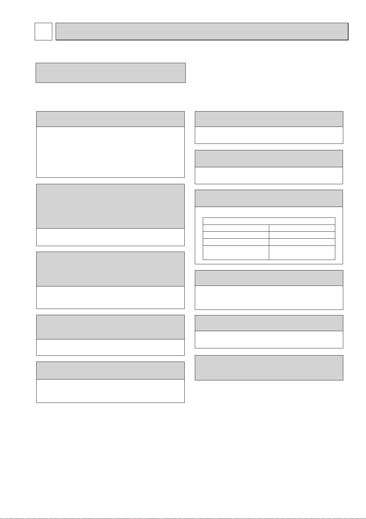
3 SAFETY PRECAUTION
3-1. ALWAYS OBSERVE FOR SAFETY
Before obtaining access to termnal, all supply
ciucuits must disconnected.
3-2. CAUTIONS RELATED TO NEW REFRIGERANT
Cautions for units utilizing refrigerant R410A
Use new refrigerant pipes.
In case of using the existing pipes for R22, be careful with
the followings.
· Be sure to clean the pipes and make sure that the insides
of the pipes are clean.
· Change flare nut to the one provided with this product.
Use a newly flared pipe.
· Avoid using thin pipes.
Make sure that the inside and outside of refrigerant piping is clean and it has no contamination
such as sulfur hazardous for use, oxides, dirt,
shaving particles, etc.
In addition, use pipes with specified thickness.
Contamination inside refrigerant piping can cause deterioration of refrigerant oil etc.
Store the piping to be used indoors during
installation and both ends of the piping sealed
until just before brazing. (Leave elbow joints, etc.
in their packaging.)
If dirt, dust or moisture enter into refrigerant cycle, that can
cause deterioration of refrigerant oil or malfunction of compressor.
Do not use refrigerant other than R410A.
If other refrigerant (R22 etc.) is used, chlorine in refrigerant can cause deterioration of refrigerant oil etc.
Use a vacuum pump with a reverse flow check
valve.
Vacuum pump oil may flow back into refrigerant cycle and
that can cause deterioration of refrigerant oil etc.
Use the following tools specifically designed for
use with R410A refrigerant.
The following tools are necessary to use R410A refrigerant.
Tools for R410A
Gauge manifold
Charge hose
Gas leak detector
Torque wrench
Flare tool
Size adjustment gauge
Vacuum pump adaptor
Electronic refrigerant
charging scale
Handle tools with care.
If dirt, dust or moisture enter into refrigerant cycle, that can
cause deterioration of refrigerant oil or malfunction of compressor.
Use ester oil, ether oil or alkylbenzene oil (small
amount) as the refrigerant oil applied to flares
and flange connections.
If large amount of mineral oil enter, that can cause deterioration of refrigerant oil etc.
Do not use a charging cylinder.
If a charging cylinder is used, the composition of refrigerant will change and the efficiency will be lowered.
Ventilate the room if refrigerant leaks during
Charge refrigerant from liquid phase of gas
cylinder.
If the refrigerant is charged from gas phase, composition
change may occur in refrigerant and the efficiency will be
lowered.
operation. If refrigerant comes into contact with
a flame, poisonous gases will be released.
[1] Cautions for service
(1) Perform service after collecting the refrigerant left in unit completely.
(2) Do not release refrigerant in the air.
(3) After completing service, charge the cycle with specified amount of refrigerant.
(4) When performing service, install a filter drier simultaneously.
Be sure to use a filter drier for new refrigerant.
[2] Additional refrigerant charge
When charging directly from cylinder
· Check that cylinder for R410A on the market is syphon type.
· Charging should be performed with the cylinder of syphon stood vertically. (Refrigerant is charged from liquid phase.)
5
Page 6
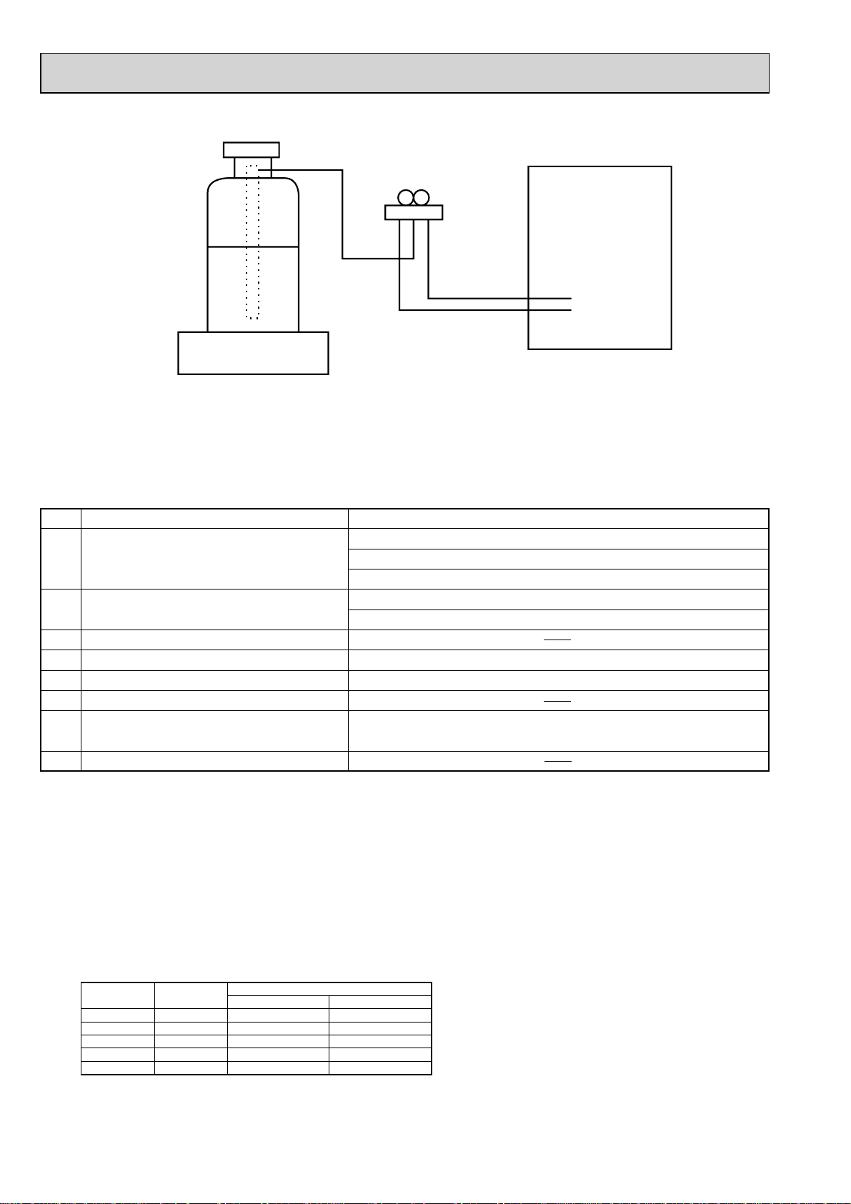
Unit
Gravimeter
[3] Service tools
Use the below service tools as exclusive tools for R410A refrigerant.
No. Tool name Specifications
1 Gauge manifold ·Only for R410A
·Use the existing fitting
·Use high-tension side pressure of 5.3MPa·G or over.
2 Charge hose ·Only for R410A
·Use pressure performance of 5.09MPa·G or over.
3 Electronic scale
4 Gas leak detector ·Use the detector for R134a, R407C or R410A.
5 Adaptor for reverse flow check ·Attach on vacuum pump.
6 Refrigerant charge base
7 Refrigerant cylinder ·Only for R410A Top of cylinder (Pink)
Cylinder with syphon
8 Refrigerant recovery equipment
specifications
. (UNF1/2)
Cautions for refrigerant piping work
New refrigerant R410A is adopted for replacement inverter series. Although the refrigerant piping work for R410A is same
as for R22, exclusive tools are necessary so as not to mix with different kind of refrigerant. Furthermore as the working
pressure of R410A is 1.6 time higher than that of R22, their sizes of flared sections and flare nuts are different.
1Thickness of pipes
Because the working pressure of R410A is higher compared to R22, be sure to use refrigerant piping with thickness
shown below. (Never use pipes of 0.7mm or below.)
Diagram below: Piping diameter and thickness
Nominal
dimensions
1/4”
3/8”
1/2”
5/8”
3/4”
Outside
diameter
6.35
9.52
12.70
15.88
19.05
(mm)
Thickness
R410A R22
0.8
0.8
0.8
1.0
—
(mm)
0.8
0.8
0.8
1.0
1.0
6
Page 7
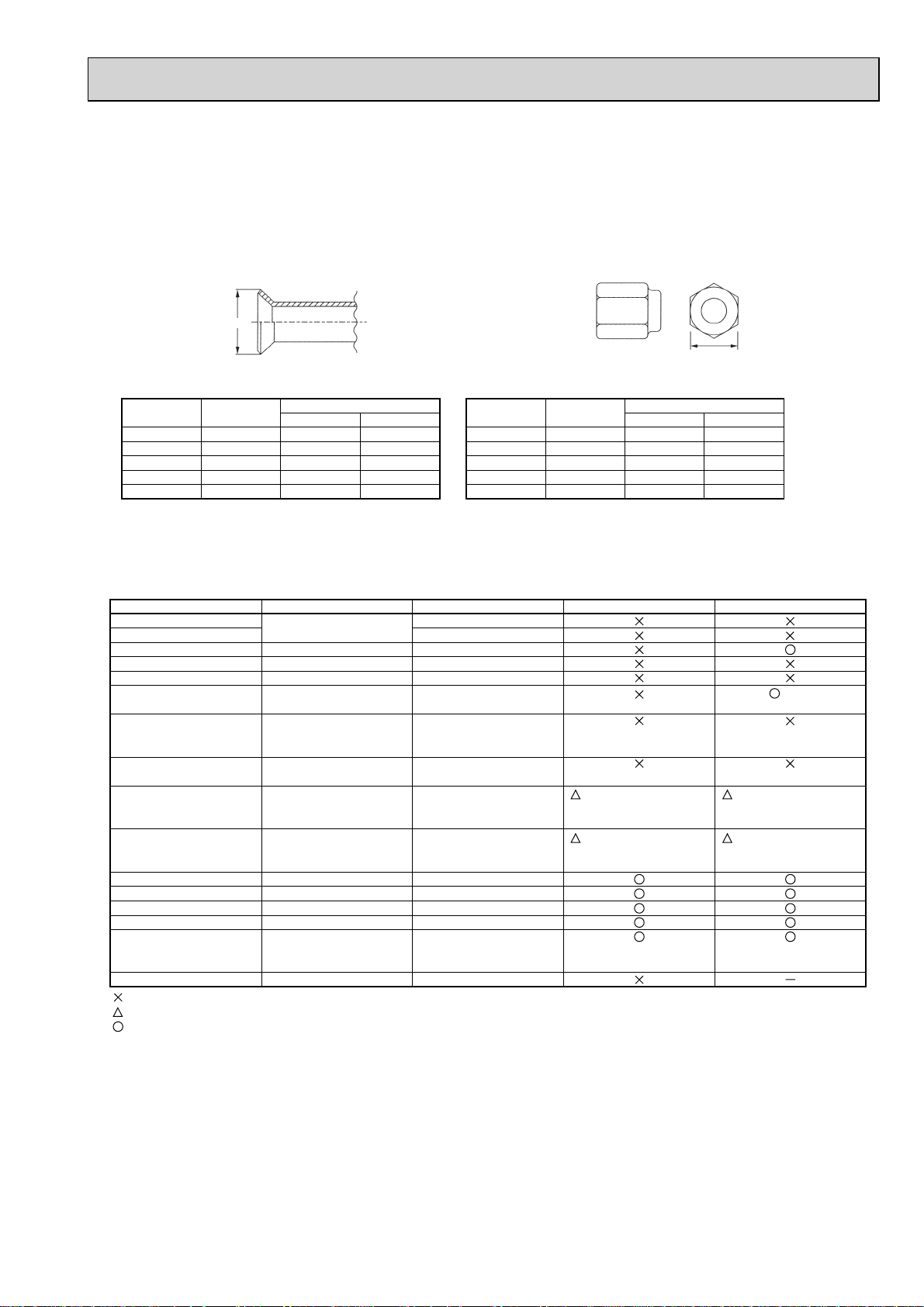
2Dimensions of flare cutting and flare nut
The component molecules in HFC refrigerant are smaller compared to conventional refrigerants. In addition to that,
R410A is a refrigerant, which has higher risk of leakage because of its working pressure higher than that of other refriger ants. Therefore, to enhance airtightness and intensity, flare cutting dimension of copper pipe for R410A have been speci fied separately from the dimensions for other refrigerants as shown below. The dimension B of flare nut for R410A also
have partly been changed to increase intensity as shown below. Set copper pipe correctly referring to copper pipe flaring
dimensions for R410A below. For 1/2” and 5/8”, the dimension B changes.
Use torque wrench corresponding to each dimension.
Dimension A
Dimension B
Flare cutting dimensions
Nominal
dimensions
1/4”
3/8”
1/2”
5/8”
3/4”
Outside
diameter
6.35
9.52
12.70
15.88
19.05
Dimension A
R410A R22
9.1
13.2
16.6
19.7
—
+0
( )
-0.4
9.0
13.0
16.2
19.4
23.3
(mm)
Flare nut dimensions
Nominal
dimensions
1/4"
3/8"
1/2"
5/8"
3/4"
Outside
diameter
6.35
9.52
12.70
15.88
19.05
Dimension B
R410A
17.0
22.0
26.0
29.0
+
–
3Tools for R410A (The following table shows whether conventional tools can be used or not.)
Tools and materials Use R410A tools Can R22 tools be used?
Gauge manifold
Charge hose
Gas leak detector
Refrigerant recovery equipment
Refrigerant cylinder
Applied oil
Safety charger
Charge valve
Vacuum pump
Flare tool
Bender
Pipe cutter
Welder and nitrogen gas cylinder
Refrigerant charging scale
Vacuum gauge or thermistor vacuum gauge and
vacuum valve
Charging cylinder
: Prepare a new tool. (Use the new tool as the tool exclusive for R410A.)
: Tools for other refrigerants can be used under certain conditions.
: Tools for other refrigerants can be used.
Air purge, refrigerant charge and
Operation check
Gas leak check
Collection of refrigerant
Refrigerant charge
Apply to flared section
Prevent compressor malfunction
when charging refrigerant by
spraying liquid refrigerant
Prevent gas from blowing out
when detaching charge hose
Vacuum drying and air
purge
Flaring work of piping
Bend the pipes
Cut the pipes
Weld the pipes
Charge refrigerant
Check the degree of vacuum. (Vacuum
valve prevents back flow of oil and refrigerant to thermistor vacuum gauge)
Charge refrigerant
Tool exclusive for R410A
Tool exclusive for R410A
Tool for HFC refrigerant
Tool exclusive for R410A
Tool exclusive for R410A
Ester oil and alkylbenzene
oil (minimum amount)
Tool exclusive for R410A
Tool exclusive for R410A
Tools for other refrigerants can
be used if equipped with adopter for reverse flow check
Tools for other refrigerants
can be used by adjusting
flaring dimension
Tools for other refrigerants can be used
Tools for other refrigerants can be used
Tools for other refrigerants can be used
Tools for other refrigerants can be used
Tools for other refrigerants
can be used
Tool exclusive for R410A
(Usable if equipped
with adopter for rever se flow)
(Usable by adjusting
flaring dimension)
(mm)
R22
17.0
22.0
24.0
27.0
36.0
Can R407C tools be used?
Ester oil:
Alkylbenzene oil: minimum amount
(Usable if equipped
with adopter for rever se flow)
(Usable by adjusting
flaring dimension)
+36.0mm for
indoor unit
of RP100,
125 and 140
7
Page 8
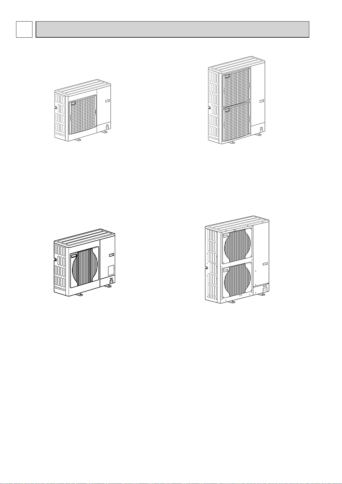
4 FEATURES
PU(H)-P71VHA(1).UK PU(H)-P71VHA#2.UK
PU(H)-P71YHA(1).UK PU(H)-P71YHA#2.UK
PU(H)-P100VHA(1).UK PU(H)-P100VHA#2.UK
PU(H)-P100YHA(1).UK PU(H)-P100YHA#2.UK
PU(H)-P71VHAR3.UK
PU(H)-P71YHAR3.UK
PU(H)-P100VHAR3.UK
PU(H)-P100YHAR3.UK
PU(H)-P125YHA(1).UK
PU(H)-P140YHA
PU(H)-P125YHA#2.UK
PU(H)-P140YHA#2.UK
PU(H)-P125YHAR3.UK
PU(H)-P140YHAR3.UK
(1).UK
CHARGELESS SYSTEM
PRE-CHARGED REFRIGERANT IS SUPPLIED FOR PIPING LENGTH AT SHIPMENT. (Max.30m)
The refrigerant circuit with LEV(Linear Expansion Valve) and Accumlator always control the optimal refrigerant
level regardless of the length (30m max. and 5m min.) of piping. The additional refrigerant charging work during
installation often causes problems. Heretofore it is completely eliminated. This unique system improves the quality
and reliability of the work done. It also helps to speed up the installation time.
8
Page 9
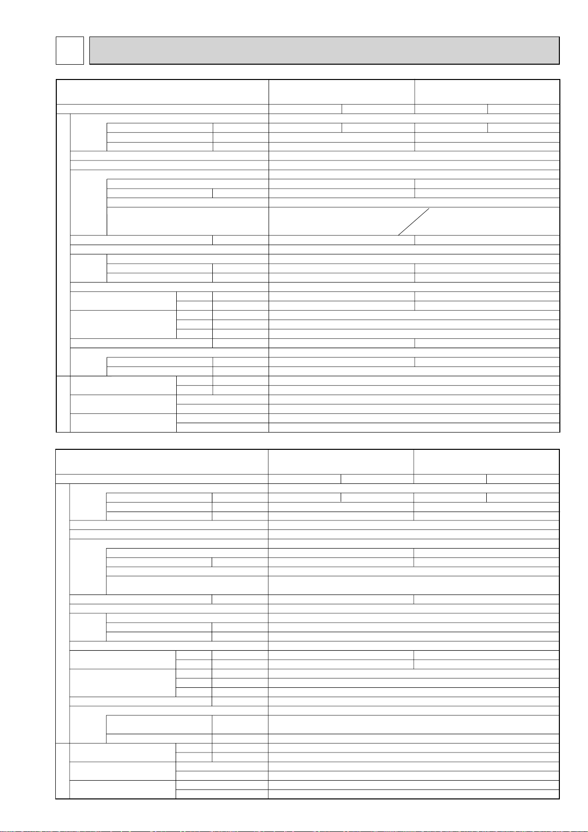
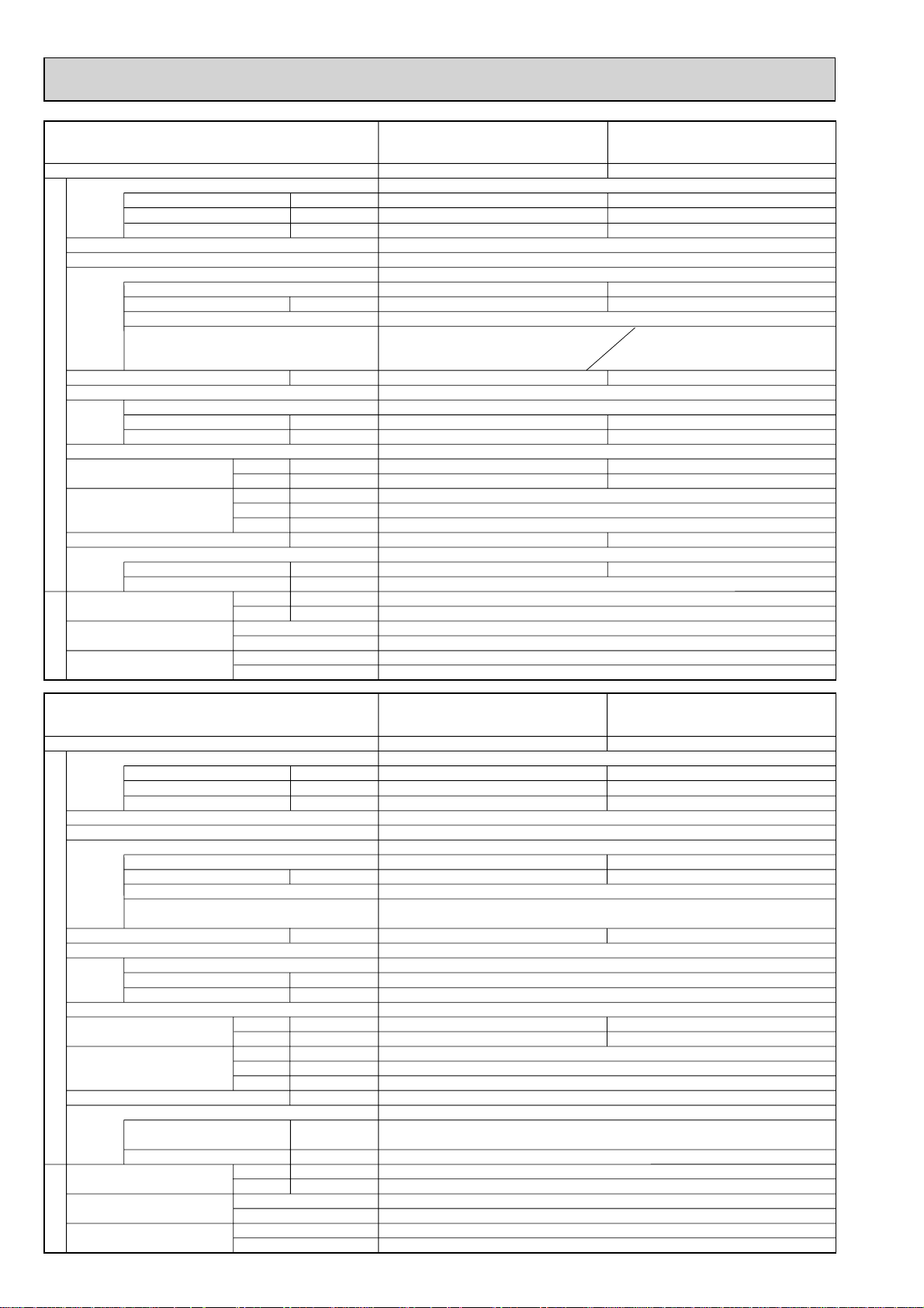
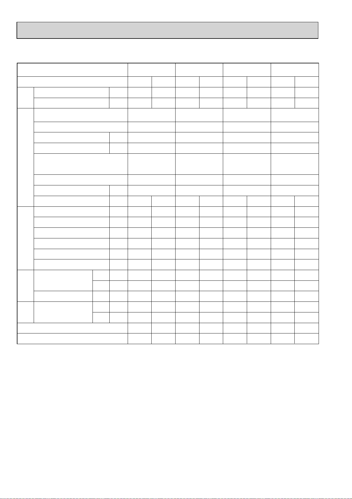
5 SPECIFICATIONS
Service Ref.
Mode
Power supply (phase, cycle, voltage)
Running current
Max. current
Protection current
External finish
Refrigerant control
Compressor
Model
Motor output
Starter type
Protection devices
Crankcase heater
Heat exchanger
Fan Fan(drive) % No.
Fan motor output
OUTDOOR UNIT
Airflow
Defrost method
Noise level
Dimensions
Weight
Refrigerant
Charge
Oil (Model)
Pipe size O.D.
Connection method
Between the indoor &
outdoor unit
REFRIGERANT PIPING
*
/min(CFM
Cooling
Heating
W
D
H
mm(in.)
mm(in.)
mm(in.)
kg(lbs)
kg(lbs)
Liquid
Gas
mm(in.)
mm(in.)
Indoor side
Outdoor side
Height difference
Piping length
A
A
A
kW
W
kW
dB
dB
PUH-P71VHA/YHA
PUH-P71VHA/YHA#2.UK
PUH-P71VHA/YHAR3.UK
Cooling
(1).UK
Heating
PUH-P100VHA/YHA
PUH-P100VHA/YHA#2.UK
PUH-P100VHA/YHAR3.UK
Cooling
(1).UK
Heating
Single, 50Hz, 230V/ 3Phase, 50Hz, 400V(4wires)
12.03/4.29
23.5/7.8
25.5/9.4
11.98/4.28
15.07/5.39
14.48/5.18
28.5/9.4
30.5/11.3
Munsell 5Y 7/1 / Munsell 3Y 7.8/1.1 (V/YHAR3)
Linear Expansion Valve
Hermetic
NN33VAAMT/ NN33YCAMT
2.2
NN40VAAMT/ NN40YCAMT
2.7
Line start
(V) Internal thermostat
HP switch
Discharge thermo
25
(Y) Thermal relay
HP switch
Discharge thermo
25
Plate fin coil
Propeller fan % 1
)
55(1940)
0.070
0.110
65(2290)
Reverse cycle
49
50
50
52
950(37-3/8)
330+30(13+1-3/16)
943(37-1/8)
93(205)
94(207)
R410A
3.6(7.9)
L
1.30(MEL56)
4.4(9.7)
9.52(3/8)
15.88(5/8)
Flared
Flared
Max. 50m
Max. 50m
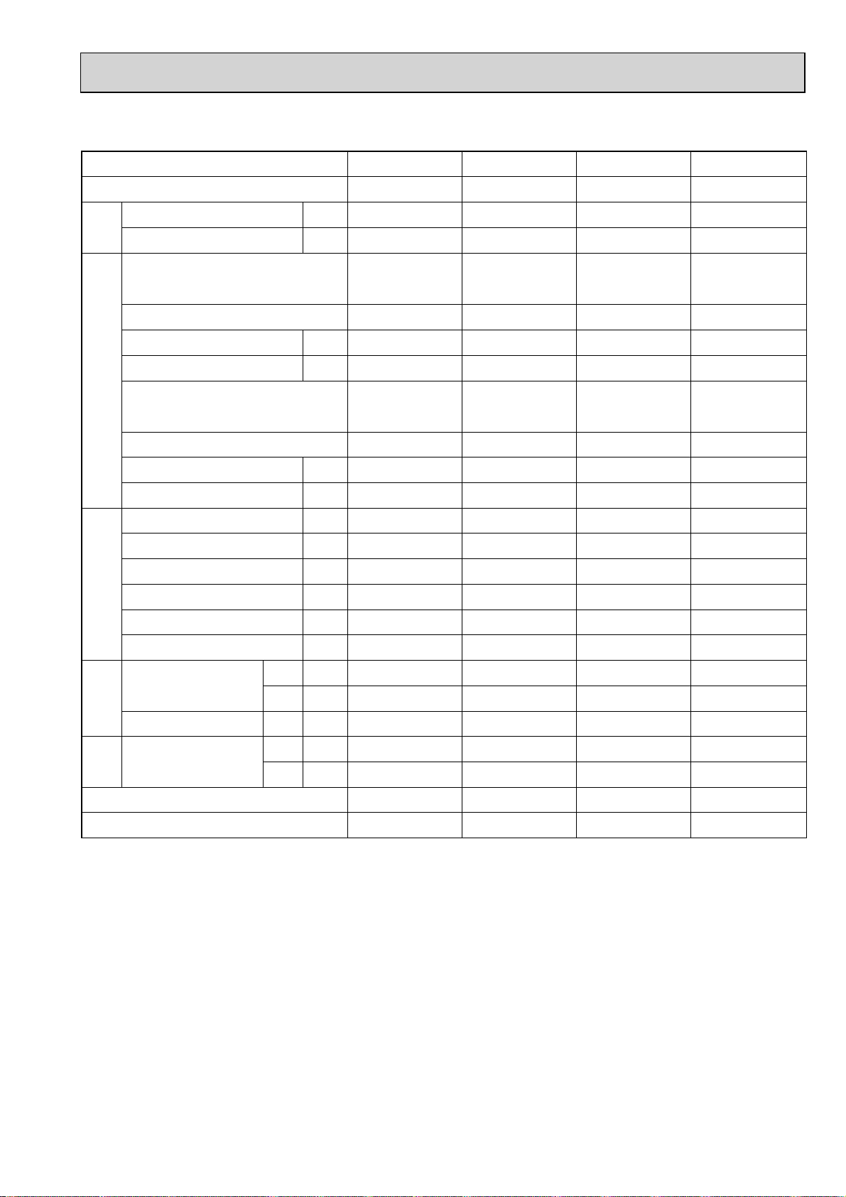
Service Ref.
Mode
Power supply (phase, cycle, voltage)
Running current
Max. current
Protection current
External finish
Refrigerant control
Compressor
Model
Motor output
Starter type
Protection devices
Crankcase heater
Heat exchanger
Fan Fan(drive) % No.
Fan motor output
Airflow
OUTDOOR UNIT
Defrost method
Noise level
Dimensions
Weight
Refrigerant
Charge
Oil (Model)
Pipe size O.D.
Connection method
Between the indoor &
outdoor unit
REFRIGERANT PIPING
*
/min(CFM
Cooling
Heating
W
D
H
Liquid
Gas
Indoor side
Outdoor side
Height difference
Piping length
mm(in.)
mm(in.)
mm(in.)
kg(lbs)
kg(lbs)
mm(in.)
mm(in.)
A
A
A
kW
W
kW
dB
dB
PUH-P125YHA
PUH-P125YHA#2.UK
PUH-P125YHAR3.UK
Cooling
6.79
BN52YEGMT or BN52YELMT
)
L
(1).UK
Heating
3Phase, 50Hz, 400V
12.6
15.1
Munsell 5Y 7/1
3.7
25
50
52
6.57
/ Munsell 3Y 7.8/1.1 (YHAR3)
Linear Expansion Valve
Hermetic
Line start
Discharge thermo, HP switch
Thermal relay
Plate fin coil
Propeller fan % 2
0.070+0.070
100(3,530)
Reverse cycle
950(37-3/8)
330+30(13+1-3/16)
1,350(53-1/8)
131(289)
5.0(11.0)
2.10(MEL56)
9.52(3/8)
15.88(5/8)
Max. 50m
Max. 50m
R410A
Flared
Flared
PUH-P140YHA
PUH-P140YHA#2.UK
PUH-P140YHAR3.UK
Cooling
8.55
BN65YEGMT or BN65YELMT
(1).UK
Heating
8.45
15.6
18.7
4.6
25
51
53
9
Page 10
Service Ref.
Mode
Power supply (phase, cycle, voltage)
Running current
Max. current
Protection curent
External finish
Refrigerant control
Compressor
Model
Motor output
Starter type
Protection devices
Crankcase heater
Heat exchanger
Fan Fan(drive) % No.
Fan motor output
OUTDOOR UNIT
Airflow
Defrost method
Noise level
Dimensions
Weight
Refrigerant
Charge
Oil (Model)
Pipe size O.D.
Connection method
Between the indoor &
outdoor unit
REFRIGERANT PIPING
*
/min(CFM
Cooling
Heating
W
D
H
mm(in.)
mm(in.)
mm(in.)
kg(lbs)
kg(lbs)
Liquid
Gas
mm(in.)
mm(in.)
Indoor side
Outdoor side
Height difference
Piping length
A
A
A
kW
W
kW
dB
dB
L
PU-P71VHA/YHA
PU-P71VHA/YHA#2.UK
PU-P71VHA/YHAR3.UK
Cooling
(1).UK
PU-P100VHA/YHA(1).UK
PU-P100VHA/YHA#2.UK
PU-P100VHA/YHAR3.UK
Cooling
Single, 50Hz, 230V / 3Phase, 50Hz, 400V(4wires)
12.03/4.29
23.5/7.8
25.5/9.4
15.07/5.18
28.5/9.4
30.5/11.3
Munsell 5Y 7/1 / Munsell 3Y 7.8/1.1(V/YHAR3)
Linear Expansion Valve
Hermetic
NN33VAAMT/ NN33YCAMT
2.2
NN40VAAMT/ NN40YCAMT
2.7
Line start
(V) Internal thermostat
HP switch
Discharge thermo
25
(Y) Thermal relay
HP switch
Discharge thermo
25
Plate fin coil
Propeller fan % 1
)
55(1940)
0.070
0.110
65(2290)
–
49
–
50
–
950(37-3/8)
330+30(13+1-3/16)
943(37-1/8)
93(205)
94(207)
R410A
3.6(7.9)
4.4(9.7)
1.30(MEL56)
9.52(3/8)
15.88(5/8)
Flared
Flared
Max. 50m
Max. 50m
Service Ref.
Mode
Power supply (phase, cycle, voltage)
Running current
Max. current
Protection current
External finish
Refrigerant control
Compressor
Model
Motor output
Starter type
Protection devices
Crankcase heater
Heat exchanger
Fan Fan(drive) % No.
Fan motor output
Airflow
OUTDOOR UNIT
Defrost method
Noise level
Dimensions
Weight
Refrigerant
Charge
Oil (Model)
Pipe size O.D.
Connection method
Between the indoor &
outdoor unit
REFRIGERANT PIPING
*
/min(CFM
Cooling
Heating
W
D
H
mm(in.)
mm(in.)
mm(in.)
kg(lbs)
kg(lbs)
Liquid
Gas
mm(in.)
mm(in.)
Indoor side
Outdoor side
Height difference
Piping length
A
A
A
kW
W
kW
dB
dB
L
PU-P125YHA
PU-P125YHA#2.UK
PU-P125YHAR3.UK
Cooling
BN52YEGMT or BN52YELMT
)
(1).UK
PU-P140YHA
PU-P140YHA#2.UK
PU-P140YHAR3.UK
Cooling
3Phase, 50Hz, 400V
6.79
12.6
15.5
8.55
15.6
18.7
Munsell 5Y 7/1 / Munsell 3Y 7.8/1.1(YHAR3)
Linear Expansion Valve
Hermetic
BN65YEGMT or BN65YELMT
3.7
Line start
Discharge thermo, HP switch
Thermal relay
25
Plate fin coil
Propeller fan % 2
0.070+0.070
100(3,530)
–
50
–
950(37-3/8)
330+30(13+1-3/16)
1,350(53-1/8)
131(289)
R410A
5.0(11.0)
2.10(MEL56)
9.52(3/8)
15.88(5/8)
Flared
Flared
Max. 50m
Max. 50m
(1).UK
4.6
25
51
–
10
Page 11
6 DATA
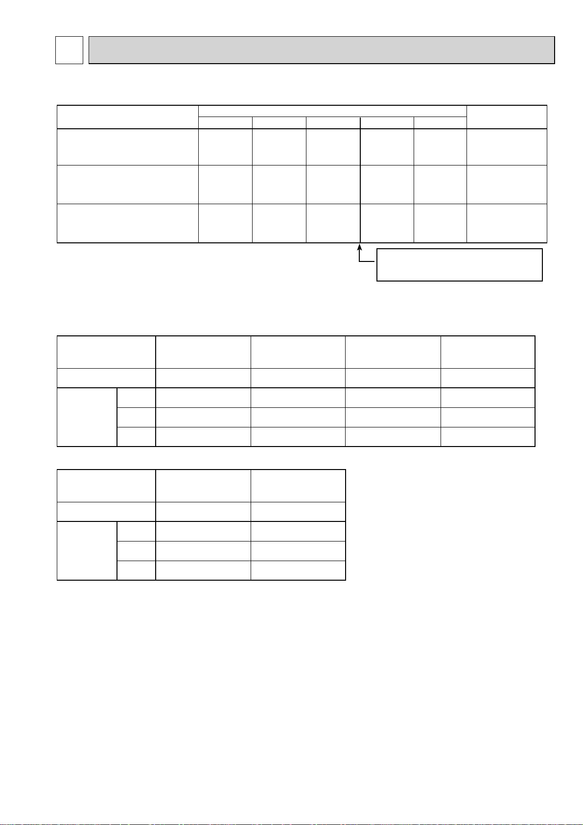
6-1. REFILLING REFRIGERANT CHARGE (R410A : kg)
Service Ref.
PU(H)-P71VHA/YHA(1).UK
PU(H)-P71VHA/YHA#2.UK
PU(H)-P71VHA/YHAR3.UK
PU(H)-P100VHA/YHA
PU(H)-P100VHA/YHA#2.UK
PU(H)-P100VHA/YHAR3.UK
PU(H)-P125/140YHA
PU(H)-P125/140YHA#2.UK
PU(H)-P125/140YHAR3.UK
(1).UK
(1).UK
10m
3.4
4.2
4.8
6-2. COMPRESSOR TECHNICAL DATA
Unit
Compressor model
U-V
Winding
Resistance
( )
(R-C)
U-W
(S-C)
W-V
PU(H)-P71VHA
PU(H)-P71VHA#2.UK
PU(H)-P71VHAR3.UK
NN33VAAMT
0.68
1.80
–
(1).UK
PU(H)-P71YHA(1).UK
PU(H)-P71YHA#2.UK
PU(H)-P71YHAR3.UK
Piping length (one way)
20m
3.5
4.3
4.9
NN33YCAMT
4.64
4.64
4.64
30m
3.6
4.4
5.0
PU(H)-P100VHA
PU(H)-P100VHA#2.UK
PU(H)-P100VHAR3.UK
40m
4.2
5.0
5.6
Longer pipe than 30m, additional
charge is required.
NN40VAAMT
0.63
1.55
–
50m
4.8
5.6
6.2
PU(H)-P100YHA
(1).UK
PU(H)-P100YHA#2.UK
PU(H)-P100YHAR3.UK
NN40YCAMT
Factory
charged
3.6
4.4
5.0
(at 20°C)
(1).UK
3.32
3.32
3.32
Unit
Compressor model
Winding
Resistance
( )
U-V
U-W
W-V
PU(H)-P125YHA(1).UK
PU(H)-P125YHA#2.UK
PU(H)-P125YHAR3.UK
BN52YEGMT
BN52YELMT
2.149
2.149
2.149
(at 20°C)
PU(H)-P140YHA(1).UK
PU(H)-P140YHA#2.UK
PU(H)-P140YHAR3.UK
BN65YEGMT
BN65YELMT
1.794
1.794
1.794
11
Page 12
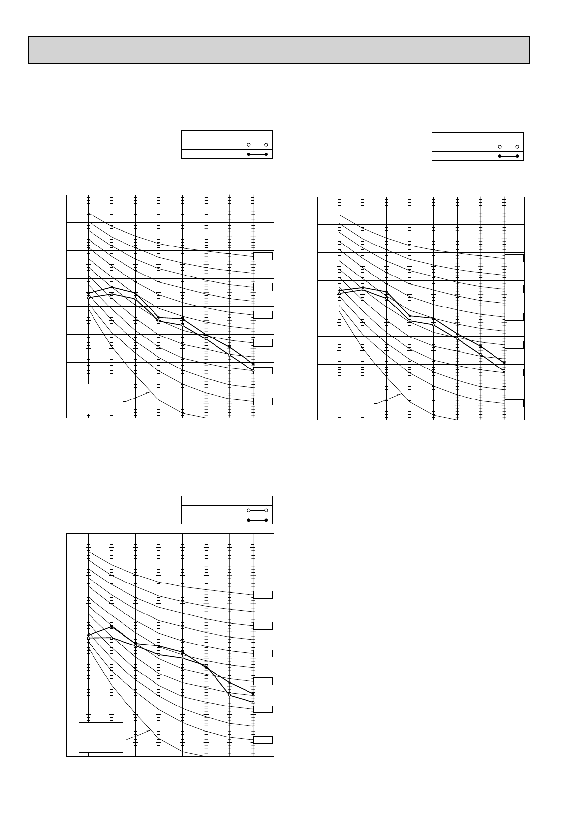
6-3. NOISE CRITERION CURVES
PU(H)-P71VHA(1).UK
PU(H)-P71YHA
(1).UK
PU(H)-P71VHA#2.UK
PU(H)-P71YHA#2.UK
PU(H)-P71VHAR3.UK
PU(H)-P71YHAR3.UK
90
80
70
60
50
40
30
APPROXIMATE
20
THRESHOLD OF
HEARING FOR
CONTINUOUS
OCTAVE BAND SOUND PRESSURE LEVEL, dB (0 dB = 0.0002 μbar)
NOISE
10
63 125 250 500 1000 2000 4000 8000
BAND CENTER FREQUENCIES, Hz
MODE
COOLING
HEATING
SPL(dB)
49
51
LINE
NC-70
NC-60
NC-50
NC-40
NC-30
NC-20
PU(H)-P100VHA(1).UK
PU(H)-P100YHA(1).UK
PU(H)-P100VHA#2.UK
PU(H)-P100YHA#2.UK
PU(H)-P100VHAR3.UK
PU(H)-P100YHAR3.UK
90
80
70
60
50
40
30
APPROXIMATE
20
THRESHOLD OF
HEARING FOR
CONTINUOUS
OCTAVE BAND SOUND PRESSURE LEVEL, dB (0 dB = 0.0002 μbar)
NOISE
10
63 125 250 500 1000 2000 4000 8000
BAND CENTER FREQUENCIES, Hz
MODE
COOLING
HEATING
SPL(dB)
50
52
LINE
NC-70
NC-60
NC-50
NC-40
NC-30
NC-20
PU(H)-P125YHA(1).UK
PU(H)-P125YHA#2.UK
PU(H)-P125YHAR3.UK
90
80
70
60
50
40
30
APPROXIMATE
20
THRESHOLD OF
HEARING FOR
CONTINUOUS
OCTAVE BAND SOUND PRESSURE LEVEL, dB (0 dB = 0.0002 μbar)
NOISE
10
63 125 250 500 1000 2000 4000 8000
BAND CENTER FREQUENCIES, Hz
MODE
COOLING
HEATING
SPL(dB)
50
52
LINE
NC-70
NC-60
NC-50
NC-40
NC-30
NC-20
12
Page 13
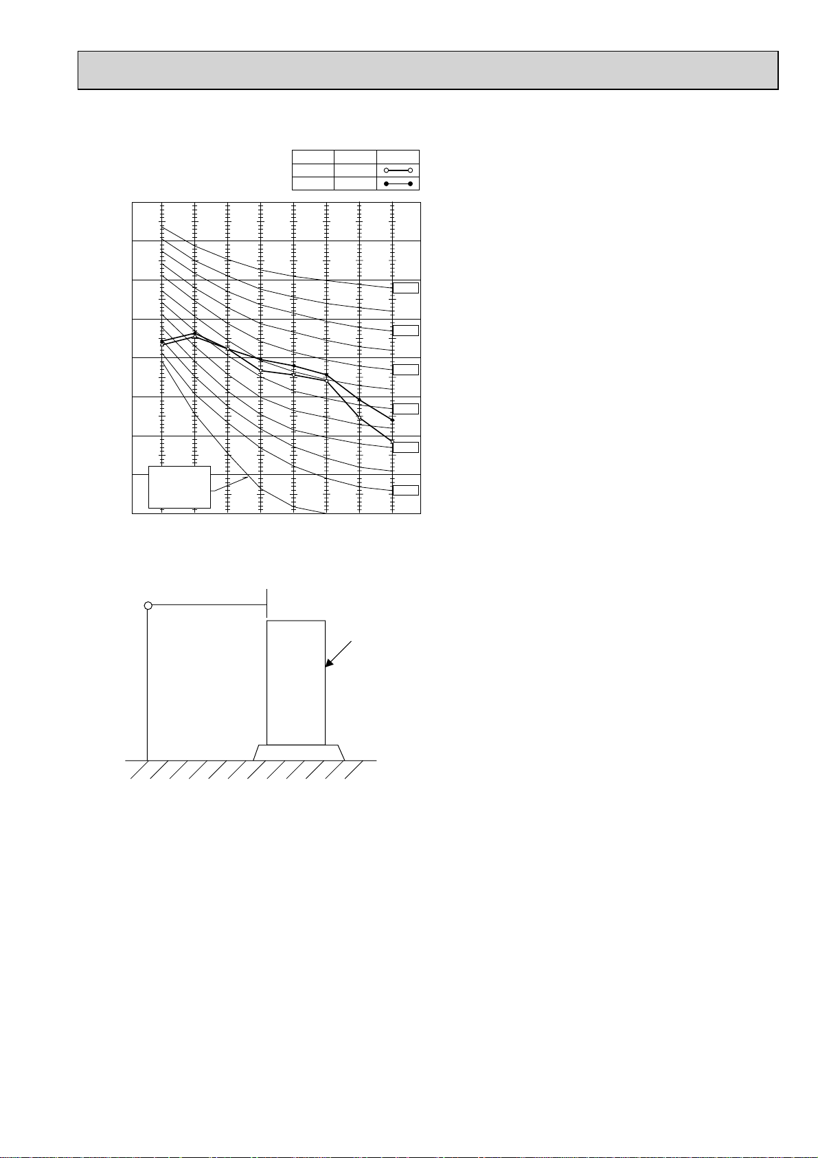
PU(H)-P140YHA(1).UK
PU(H)-P140YHA#2.UK
PU(H)-P140YHAR3.UK
90
80
MODE
COOLING
HEATING
SPL(dB)
51
53
LINE
70
60
50
40
30
APPROXIMATE
20
THRESHOLD OF
HEARING FOR
CONTINUOUS
OCTAVE BAND SOUND PRESSURE LEVEL, dB (0 dB = 0.0002 μbar)
NOISE
10
63 125 250 500 1000 2000 4000 8000
MICROPHONE
NC-70
NC-60
NC-50
NC-40
NC-30
NC-20
BAND CENTER FREQUENCIES, Hz
1m
UNIT
1.5m
GROUND
13
Page 14
6-4. STANDARD OPERATION DATA
Representative matching
Mode
Capacity
To ta lElectrical circuitRefrigerant circuitIndoor side
Input
Indoor unit
Phase , Hz
Volts
Amperes
Outdoor unit
Phase , Hz
Volts
Amperes
Discharge pressure
Suction pressure
Discharge temperature
W
kW
V
A
V
A
MPa
(.f/%)
MPa
(.f/%)
C
PLA-RP71AA PLA-RP100AA2
Cooling
8,000
2.83
PLA-RP71AA PLA-RP100AA2
PUH-P71VHA
PUH-P71YHA
12.03/4.29
2.99
(30.4)
0.79
(8.0)
76.9
Heating
1 , 50
230
0.79
1/3 , 50
230/400
11.98/4.28
9,000
2.82
2.55
(26.0)
0.53
(5.4)
85.1
Cooling
10,000
3.53
1 , 50
230
0.92
PUH-P100VHA
PUH-P100YHA
1/3 , 50
230/400
15.07/5.39
3.16
(32.2)
0.91
(9.3)
78.2
14.48/5.18
Heating
11,500
3.40
2.67
(27.2)
0.74
(7.5)
81.4
PLA-RP125AA2
Cooling
12,300
4.36
PLA-RP125AA2
PUH-P125YHA
6.79
3.00
(30.6)
0.75
(7.7)
80.5
1 , 50
230
0.92
3 , 50
400
Heating
14,300
4.23
6.57
2.97
(30.3)
0.74
(7.5)
78.1
PLA-RP140AA2
Cooling
14,200
5.41
PLA-RP140AA2
PUH-P140YHA
8.55
3.05
(31.1)
0.94
(9.6)
78.0
1 , 50
230
0.92
3 , 50
400
Heating
17,000
5.35
8.45
3.68
(37.5)
0.61
(6.2)
82.4
Condensing temperature
Suction temperature
Ref. pipe length
Intake air temperature
Discharge air temperature
Intake air temperature
side
Outdoor
SHF
BF
D.B.
W.B.
D.B.
D.B.
W.B.
C
C
m
C
C
C
C
C
49.7
3.8
5
27
19
12.8
35
24
0.74
0.11
41.0
6.5
5
20
15
44.5
7
6
—
—
49.9
4.2
5
27
19
13.4
35
24
0.78
0.06
40.9
4.0
5
20
15
42.2
7
6
—
—
38.7
2.4
5
27
19
12.3
35
24
0.74
0.05
The unit of pressure has been changed to MPa based on international SI system.
The conversion factor is : 1(MPa)=10.2(kgf/cm2)
46.2
-0.5
5
20
15
46.1
7
6
—
—
49.9
-0.8
5
27
19
11. 2
35
24
0.70
0.08
56.3
-1.2
5
20
15
51.6
7
6
—
—
14
Page 15
Representative matching
Mode
Capacity
To ta lElectrical circuitRefrigerant circuitIndoor side
Input
W
kW
PLA-RP71AA PLA-RP100AA2
Cooling
8,000
2.83
Cooling
10,000
3.53
PLA-RP125AA2
Cooling
12,300
4.36
PLA-RP140AA2
Cooling
14,200
5.41
Indoor unit
Phase , Hz
Volts
Amperes
Outdoor unit
Phase , Hz
Volts
Amperes
Discharge pressure
Suction pressure
Discharge temperature
Condensing temperature
Suction temperature
Ref. pipe length
Intake air temperature
Discharge air temperature
Intake air temperature
side
Outdoor
SHF
BF
D.B.
W.B.
D.B.
D.B.
W.B.
V
A
V
A
MPa
(.f/%)
MPa
(.f/%)
C
C
C
m
C
C
C
C
C
PLA-RP71AA PLA-RP100AA2
1 , 50
230
0.79
PU-P71VHA
PU-P71YHA
1/3 , 50
230/400
12.03/4.29
2.99
(30.4)
0.79
(8.0)
76.9
49.7
3.8
5
27
19
12.8
35
24
0.74
0.11
1 , 50
230
0.92
PU-P100VHA
PU-P100YHA
1/3 , 50
230/400
15.07/5.39
3.16
(32.2)
0.91
(9.3)
78.2
49.9
4.2
5
27
19
13.4
35
24
0.78
0.06
PLA-RP125AA2
1 , 50
230
0.92
PU-P125YHA PU-P140YHA
3 , 50
400
6.79
3.00
(30.6)
0.75
(7.7)
80.5
38.7
2.4
5
27
19
12.3
35
24
0.74
0.05
PLA-RP140AA2
1 , 50
230
0.92
3 , 50
400
8.55
3.05
(31.1)
0.94
(9.6)
78.0
49.9
-0.8
5
27
19
11. 2
35
24
0.70
0.08
The unit of pressure has been changed to MPa based on international SI system.
The conversion factor is : 1(MPa)=10.2(kgf/cm2)
15
Page 16
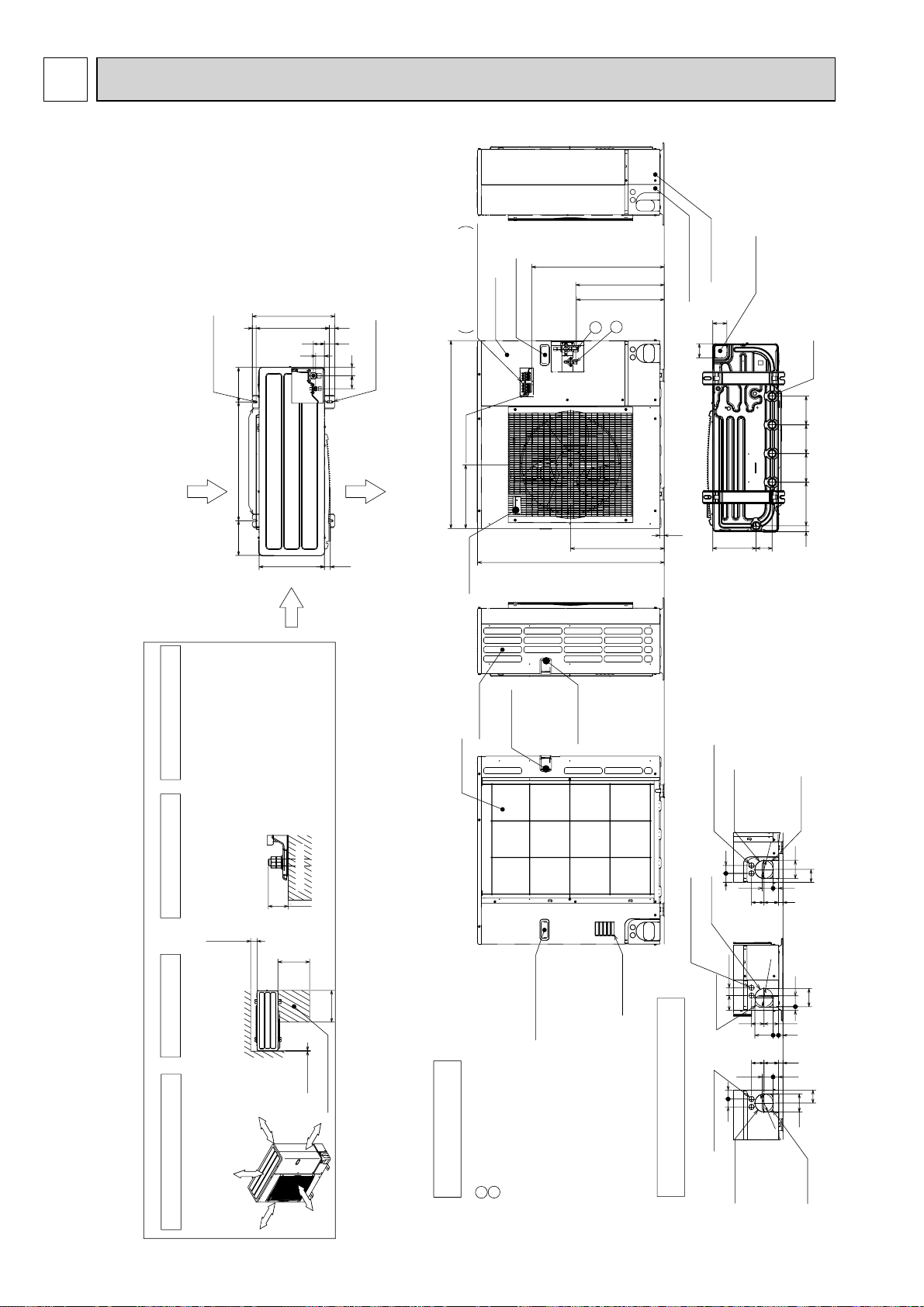
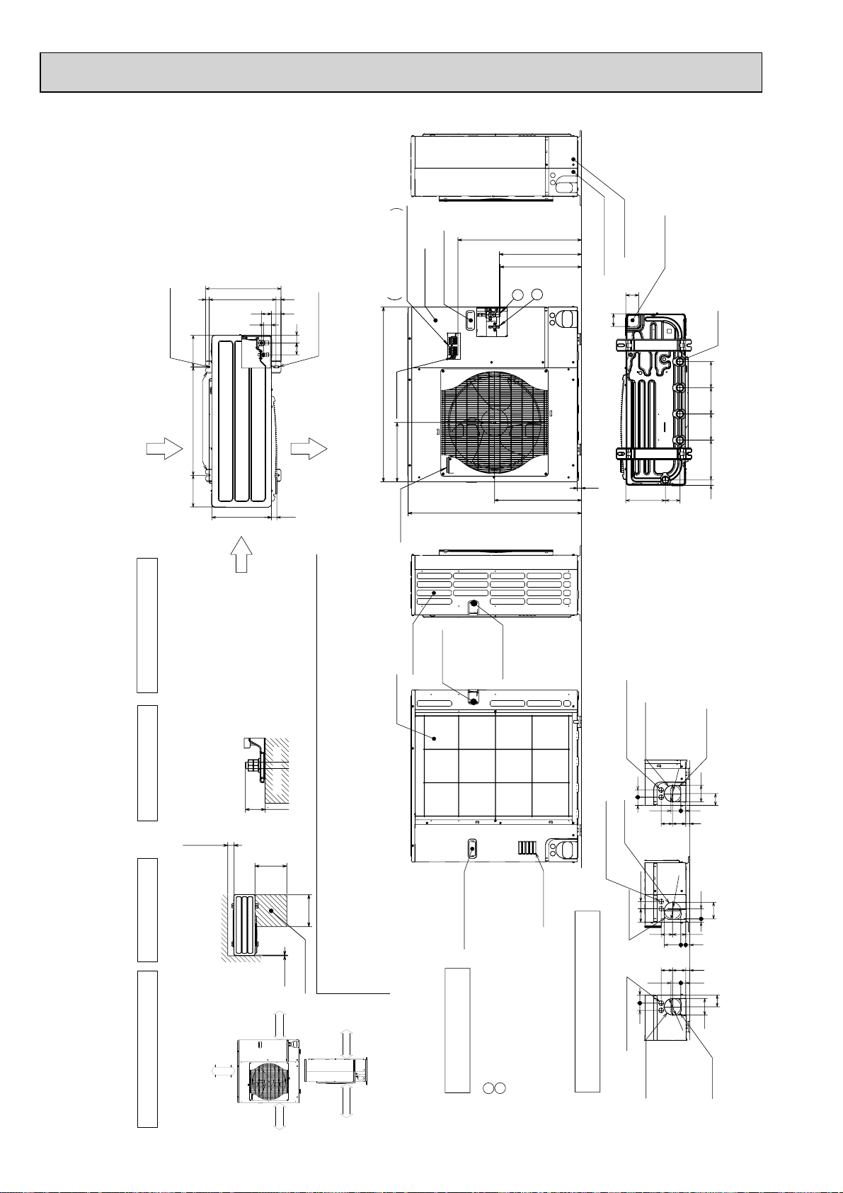
7 OUTLINES AND DIMENSIONS
417
66 42
45
56
(19)370
28
53
175600175
330
2-12%36 oval holes
(Foundation Bolt M10)
Air Discharge
Rear Air Intake
Side Air Intake
2-U Shaped notched holes
(Foundfation Bolt M10)
Installation Feet
30
Over
Over
Less than
Piping and wiring connections
can be made from 4 directions:
FRONT,Right,Rear and Below.
4 PIPING-WIRING DIRECTIONS
3 FOUNDATION BOLTS2 SERVICE SPACE
1 FREE SPACE (Around the unit)
Piping Knockout Hole Details
Example of Notes
···Refrigerant GAS pipe connction (FLARE)W15.88(5/8F)
···Refrigerant LIQUID pipe connection (FLARE)W 9.52(3/8F)
+1 ···Indication of STOP VALVE connection location.
1
2
Over 10mm
Ove
r 500mm
The diagram below shows a
basic example.
Explantion of particular details are
given in the installation manuals etc.
Over 10mm
Over 100mm
FREE
Over10
500
500
Over100
Dimensions of space needed
for service access are
shown in the below diagram.
Service space
30
Please secure the unit firmly
with 4 foundation (M10) bolts.
(Bolts and washers must be
purchased locally.)
<Foundation bolt height>
Handle for moving
Side Air Intake
Front piping cover
Rear piping cover
14522030 145
81 219
145
71
71
Drain hole
(5-W33)
Bottom piping hole
(Knockout)
Air Intake
Rear Air Intake
Handle for moving
Handle for moving
23
943
473
950
322
+1 447
+1 443
670
Terminal Connections
Left···Power supply wiring
Reight···Indoor/Outdoor wiring
Earth terminal
Service panel
Handle for moving
Handle for moving
1
2
19 55
23 27 92
92
4075
73 63
Right piping hole
(Knockout)
Right trunking hole
(Knockout)
Power supply wiring hole
(2-W27Knockout)
W
92
27 55
73
23
63
40
92
65
45
Front piping hole
(Knockout)
Front trunking hole
(Knockout)
Power supply wiring hole
(2-W27Knockout)
W
92
4045
65
92
27 55
23
73 63
Rear piping hole
(Knockout)
Rear trunking hole
(Knockout)
Power supply wiring hole
(2-W27Knockout)
W
92
FOUNDATION
PU(H)-P71VHA.UK PU(H)-P71VHA#2.UK
PU(H)-P71YHA.UK PU(H)-P71YHA#2.UK
PU(H)-P100VHA.UK PU(H)-P100VHA#2.UK
PU(H)-P100YHA.UK PU(H)-P100YHA#2.UK
PU(H)-P71VHA
1.UK
PU(H)-P71YHA1.UK
PU(H)-P100VHA1.UK
PU(H)-P100YHA1.UK
Unit : mm
16
Page 17
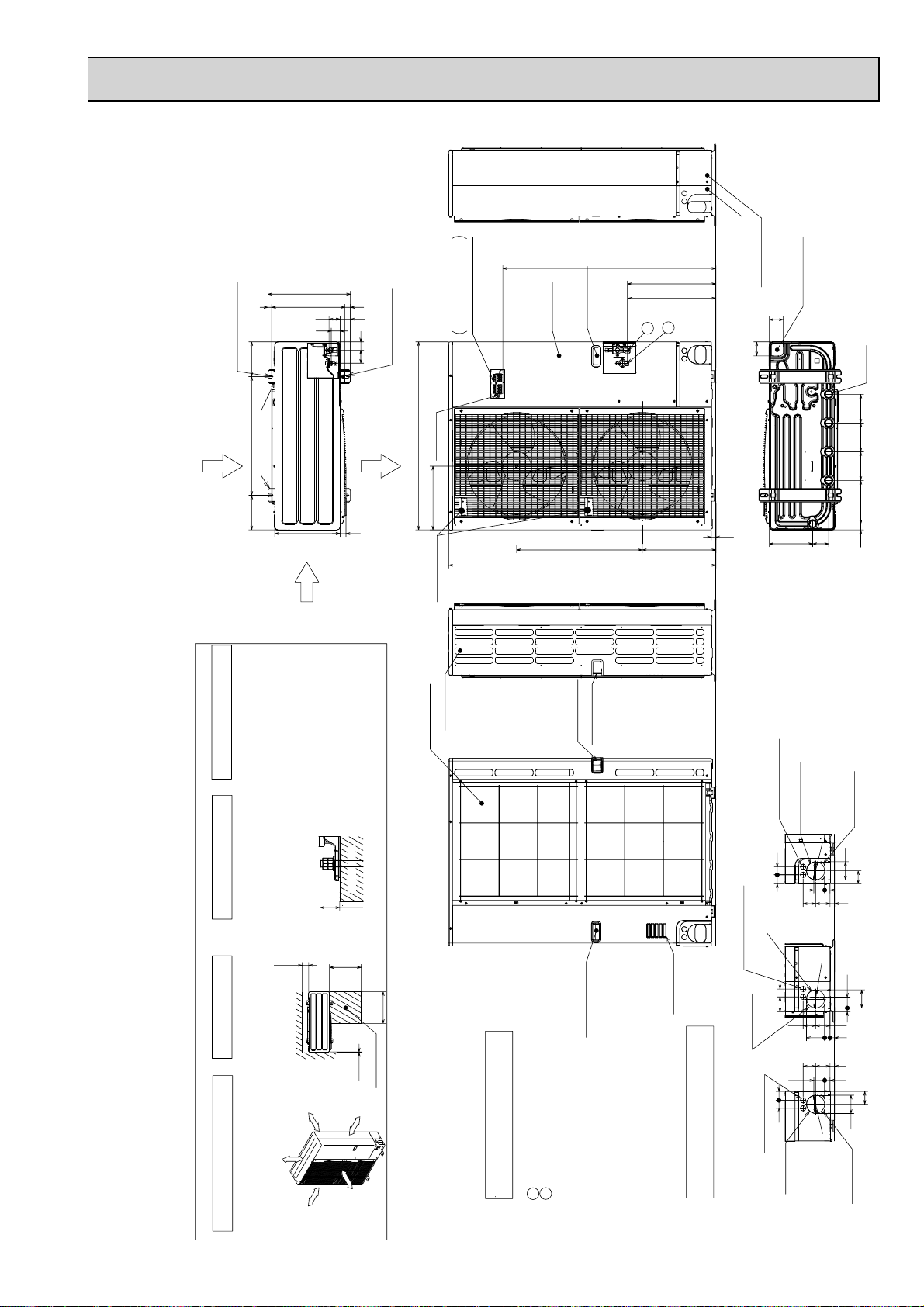
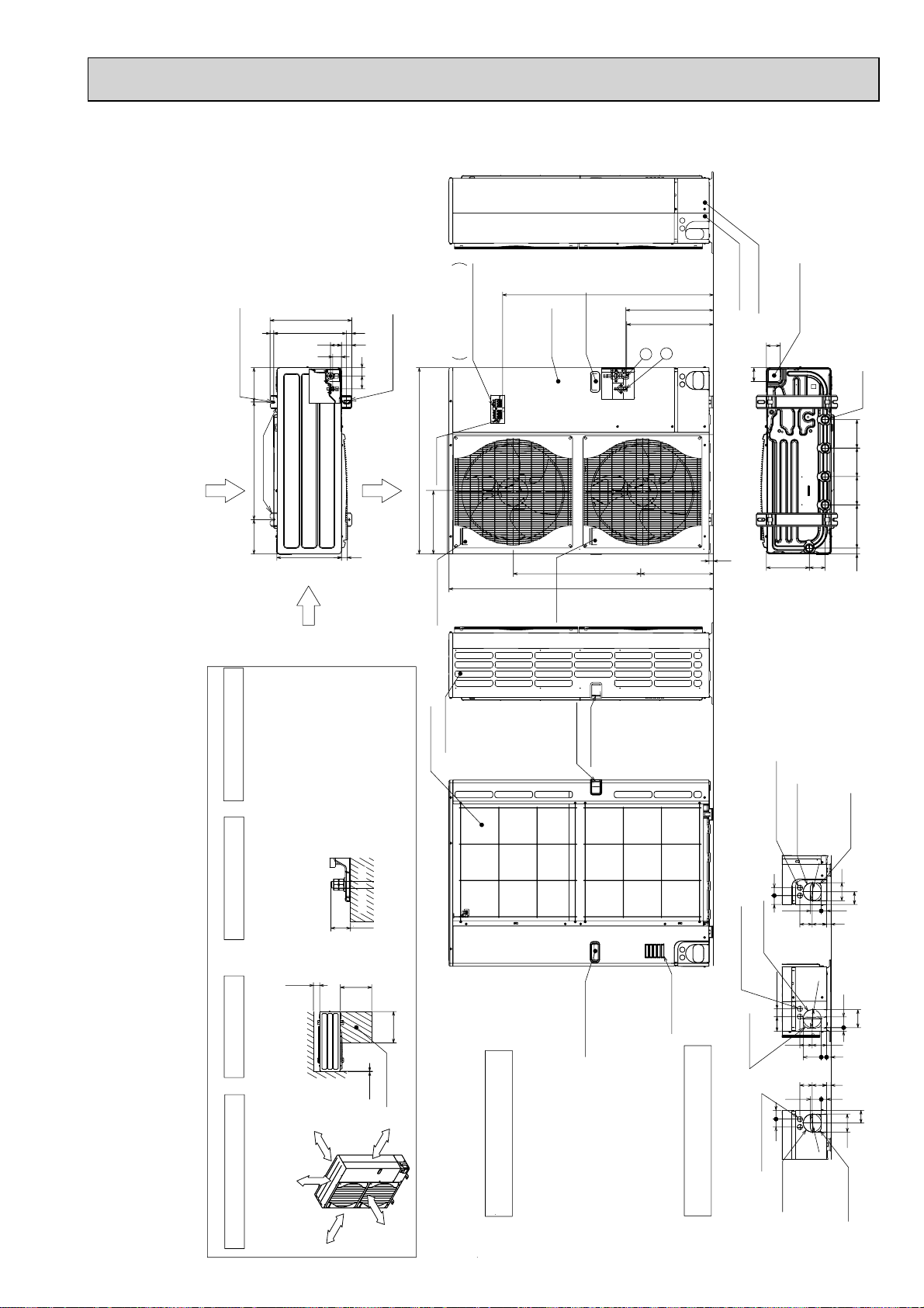
PU-P125YHA.UK PUH-P125YHA.UK
Less than
Over
Over
Over
Over
Handle for moving
Side Air Intake
Front piping cover
Rear piping cover
Air intake
Rear Air Intake
Handle for moving
Handle for moving
Terminal connection
Left···Power supply wiring
Right···Indoor/Outdoor wiring
Earth terminal
Service panel
Handle for moving
1
2
The diagram below shows a
basic example.
Explantion of particular details are
given in the installation manuals etc.
Dimensions of space needed
for service access are
shown in the below diagram.
<Foundation bolt height>
Please secure the unit firmly
with 4 foundation (M10) bolts.
(Bolts and washers must be
purchased locally.)
Air Discharge
Rear Air Intake
Side Air Intake
2
1
···Refrigerant GAS pipe connction (FLARE)W15.88(5/8F)
···Refrigerant LIQUID pipe connection (FLARE)W 9.52(3/8F)
+1 ···Indication of STOP VALVE connection location.
Example of Notes
Piping Knockout Hole Details
1 FREE SPACE (Around the unit)
2 SERVICE SPACE
3 FOUNDATION BOLTS
4 PIPING-WIRING DIRECTIONS
Piping and wiring connections
can be made from 4 directions:
FRONT,Right,Rear and Below.
Ove
r1000mm
Ove
r 1
50mm
Over 1
0mm
Over 10mm
FREE
30
FOUNDATION
150
500
500
10
Service space
600175 175
330
417
42
66
53 56
45
(19)28 370
2-U Shaped notched holes
(Foundation Bolt M10)
2-12 x 36 Oval holes
(Foundation Bolt M10)
Installation Feet
30
45 40
65
92
27 55
23 73 63
Rear piping hole
(Knockout)
Rear trunking hole
(Knockout)
Power supply wiring hole
(2-
W
27Knockout)
W
92
19 55
92
75 40
73 63
23 27 92
Right piping hole
(Knockout)
Right trunking hole
(Knockout)
Power supply wiring hole
(2-
W
27Knockout)
W
92
92
65
4540
27 55
23
73 63
Front piping hole
(Knockout)
Front trunking hole
(Knockout)
Power supply wiring hole
(2-
W
27Knockout)
W
92
14514522030 145
81 219
71
71
Bottom piping hole
(Knockout)
Drain hole
(5-W33)
1350
23
950
1076
+1 447
+1 443
371 635
322
Handle for moving
PU-P140YHA.UK PUH-P140YHA.UK
PU-P125YHA
PU-P140YHA
1.UK PUH-P125YHA1.UK
1.UK PUH-P140YHA1.UK
PU-P125YHA#2.UK PUH-P125YHA#2.UK
PU-P140YHA#2.UK PUH-P140YHA#2.UK
Unit : mm
17
Page 18
417
66 42
45
56
(19)37028
53
175600175
330
2-12%36 oval holes
(Foundation Bolt M10)
Air Discharge
Rear Air Intake
Side Air Intake
2-U Shaped notched holes
(Foundfation Bolt M10)
Installation Feet
30
Piping Knockout Hole Details
Example of Notes
···Refrigerant GAS pipe connction (FLARE)W15.88(5/8F)
···Refrigerant LIQUID pipe connection (FLARE)W 9.52(3/8F)
+1 ···Indication of STOP VALVE connection location.
1
2
Handle for moving
Side Air Intake
Front piping cover
Rear piping cover
14522030 145
81 219
145
71
71
Drain hole
(5-W33)
Bottom piping hole
(Knockout)
Air Intake
Rear Air Intake
Handle for moving
Handle for moving
19 55
23 27 92
92
4075
73 63
Right piping hole
(Knockout)
Right trunking hole
(Knockout)
Power supply wiring hole
(2-W27Knockout)
W
92
27 55
73
23
63
40
92
65
45
Front piping hole
(Knockout)
Front trunking hole
(Knockout)
Power supply wiring hole
(2-W27Knockout)
W
92
4045
65
92
27 55
23
73 63
Rear piping hole
(Knockout)
Rear trunking hole
(Knockout)
Power supply wiring hole
(2-W27Knockout)
W
92
Over
Over
Less than
Piping and wiring connections
can be made from 4 directions:
front, right, rear and below.
4 PIPING-WIRING DIRECTIONS
3 FOUNDATION BOLTS2 SERVICE SPACE
1 FREE SPACE (Around the unit)
The diagram below shows a
basic example.
Explantion of particular details is
given in the installation manuals etc.
Over10
500
500
Over100
Dimensions of space needed
for service access are
shown in the below diagram.
Service space
30
Please secure the unit firmly
with 4 foundation (M10) bolts.
(Bolts and washers must be
purchased locally.)
<Foundation bolt height>
FOUNDATION
over 100mm
over 500mm
over 10mm
FREE
over 10mm
322
950
473
943
23
*1 447
*1 443
670
2
1
Handle for moving
Handle for moving
Service panel
Earth terminal
Left···Power supply wiring
Reight···Indoor/Outdoor wiring
Terminal Connections
PU-P71VHAR3.UK PUH-P71VHAR3.UK
PU-P71YHAR3.UK PUH-P71YHAR3.UK
PU-P100VHAR3.UK PUH-P100VHAR3.UK
PU-P100YHAR3.UK PUH-P100YHAR3.UK
Unit : mm
18
Page 19
PU-P125YHAR3.UK PUH-P125YHAR3.UK
PU-P140YHAR3.UK PUH-P140YHAR3.UK
Unit : mm
(19)
2-U Shaped notched holes
(Foundation Bolt M10)
600175 175
Rear Air Intake
Installation Feet
Side Air Intake
417
330
1076
28 370
53 56
45
42
66
2-12 × 36 Oval holes
(Foundation Bolt M10)
Air Discharge
30
Terminal connection
950
Earth terminal
322
Left···Power supply wiring
Right···Indoor/Outdoor wiring
Handle for moving
Service panel
Handle
for
moving
Handle for moving
635
1350
2
1
371
+1 447
+1 443
Front piping cover
Rear piping cover
71
71
23
Bottom piping hole
(Knockout)
81 219
Drain hole
(5-W33)
14514522030 145
Piping and wiring connections
can be made from 4 directions:
front, right, rear and below.
4 PIPING-WIRING DIRECTIONS
FOUNDATION
Please secure the unit firmly
with 4 foundation (M10) bolts.
(Bolts and washers must be
3 FOUNDATION BOLTS
2 SERVICE SPACE
purchased locally.)
150
Over
Dimensions of space needed
for service access are
shown in the below diagram.
FREE
30
<Foundation bolt height>
Less than
500
Over
500
Over
10
Over
Service space
50mm
Over 1
0mm
Over 1
Rear Air Intake
Side Air Intake
Handle for moving
Handle for moving
Handle for moving
Air intake
27Knockout)
W
Power supply wiring hole
(2-
Rear trunking hole
(Knockout)
45 40
Right trunking hole
(Knockout)
27Knockout)
W
Power supply wiring hole
(2-
75 40
Right piping hole
(Knockout)
4540
27Knockout)
W
Power supply wiring hole
(2-
92
W
73 63
92
W
73 63
92
W
Rear piping hole
(Knockout)
92
65
27 55
23
92
19 55
73 63
23 27 92
23
27 55
65
92
1 FREE SPACE (Around the unit)
The diagram below shows a
basic example.
Explantion of particular details is
given in the installation manuals etc.
Over 10mm
Over 1000mm
19
Example of Notes
···Refrigerant GAS pipe connction (FLARE)W15.88(5/8F)
···Refrigerant LIQUID pipe connection (FLARE)W 9.52(3/8F)
+1 ···Indication of STOP VALVE connection location.
Piping Knockout Hole Details
Front trunking hole
(Knockout)
Front piping hole
(Knockout)
Page 20
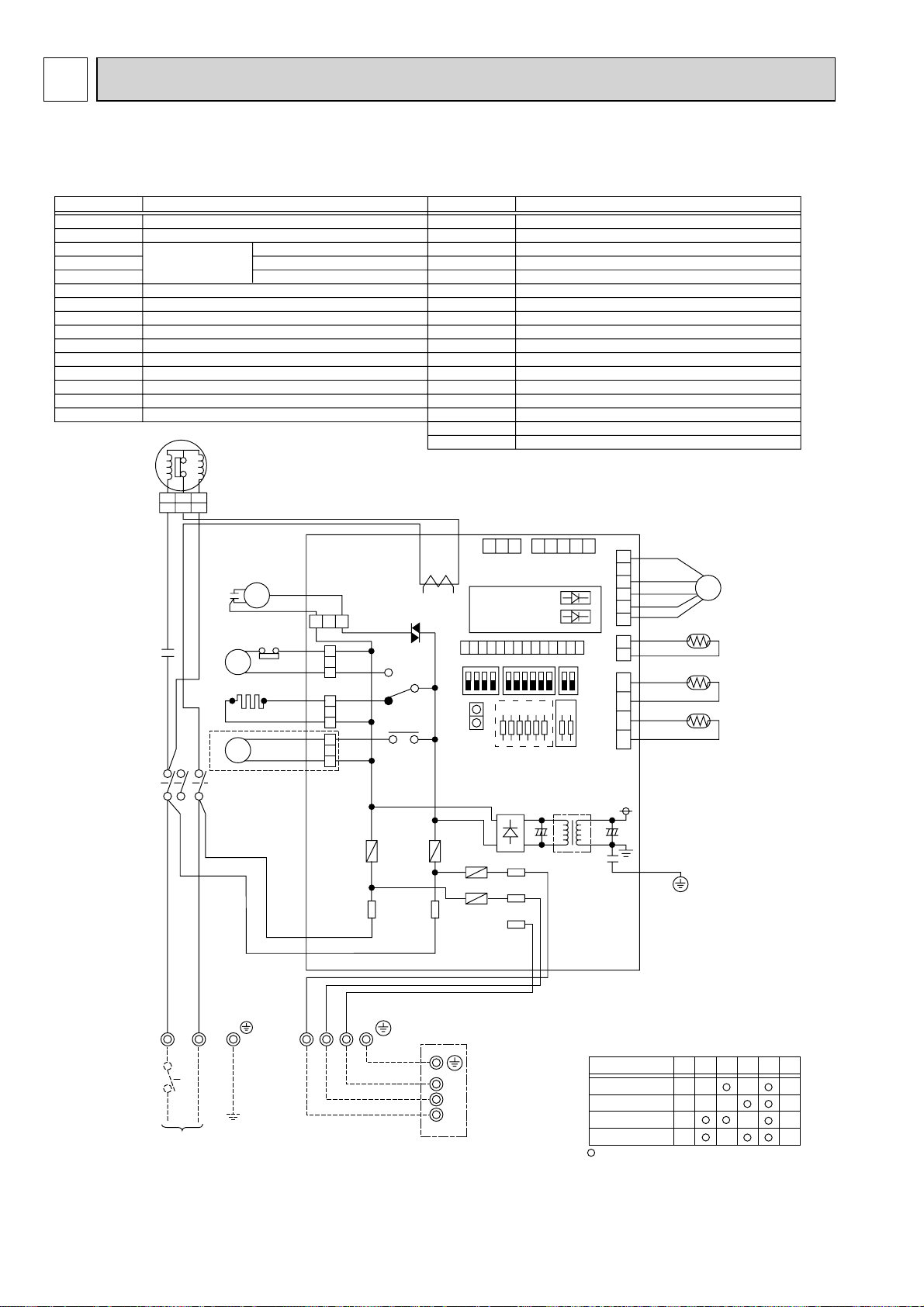
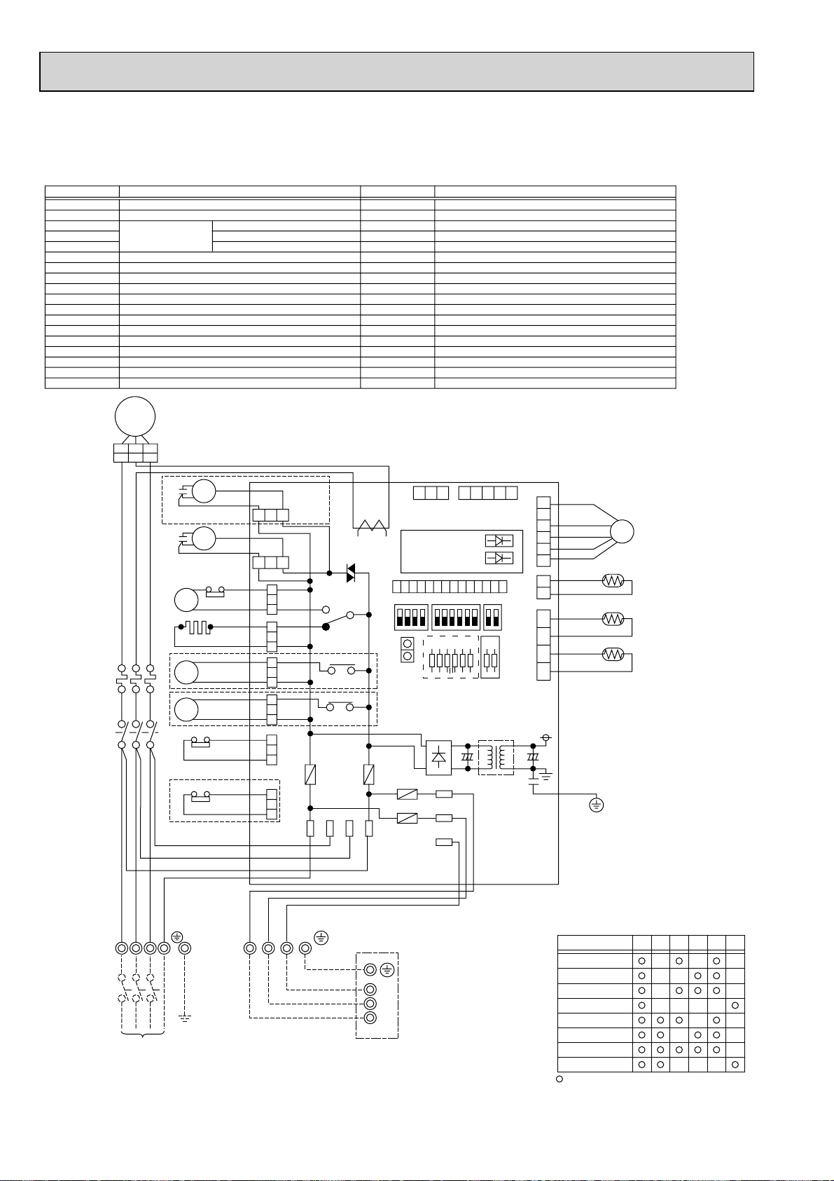
8 WIRING DIAGRAM
PU-P71VHA.UK PUH-P71VHA.UK PU-P100VHA.UK PUH-P100VHA.UK
PU-P71VHA
1.UK PUH-P71VHA1.UK PU-P100VHA1.UK PUH-P100VHA1.UK
SYMBOL
MC
MF
TH3
TH4
TH6
C3
C5
CH
52C
21S4
63H
49C
TB1
LEV
O.B
NAME
COMPRESSOR(INNER THERMOSTAT)
FAN MOTOR(INNER THERMOSTAT)
THERMISTOR
LIQUID TEMP
DISCHARGE TEMP
COND./EVA.TEMP
MF CAPACITOR
MC CAPACITOR
CRANKCASE HEATER
MC CONTACTOR
4-WAY VALVE SOLENOID COIL
HIGH PRESSURE PROTECT SWITCH
INNER THERMOSTAT FOR MC
TERMINAL BLOCK
LINEAR EXPANSION VALVE
OUTDOOR CONTROLLER BOARD
49C
MC
A1A1A2A2B1
B1
S
C
R
R
W
B
E
H
C5
L
D
T
U
2
6
/
/
T
T
1
3
1
5
/
/
L
L
1
3
C3
CH
52C
52C
21S4
MF
a
b
63H
BLU
RED
MF3
(WHT)
13
52C
(PNK)
3131 31
CH
(BLU)
21S4
(GRN)
+1
4/S R
X51
X52
FUSE2
FUSE1(O.B)
FUSE2(O.B)
FUSE3(O.B)
FUSE4(O.B)
X51 (O.B)
X52 (O.B)
F.C (O.B)
SW1 (O.B)
SW4 (O.B)
SW5 (O.B)
JA,JB (O.B)
JI~J6 (O.B)
T (O.B)
CT (O.B)
LED1 (O.B)
LED2 (O.B)
CN31 (O.B)
CT
F. C
CNM
SYMBOL
321 12345
CNVMNT
(WHT)
LED1(GRN)
LED2(RED)
1011121314
SW5
ON
OFF
J1J2J3J4J5
CN31
FUSE1
FUSE4
FUSE3
NAME
FUSE (6.3A 250V)
FUSE (6.3A 250V)
FUSE (6.3A 250V)
FUSE (6.3A 250V)
MC/CH RELAY
21S4 RELAY
FAN CONTROLLER
GROUP NUMBER ADDRESS
TEST RUN
FUNCTION SELECTION
JUMPER WIRE
MODEL SELECTION +2
TRANSFORMER
CURRENT TRANS
OPERATION CHECK DISPLAY LED
OPERATION CHECK DISPLAY LED
EMERGENCY OPERATION CONNECTER
O.B
CNMNT
SW1 SW4
S1
S2
S3
(WHT)
J6
+2
CNLEV
(WHT)
123456789
(WHT)
TH3/TH6
JA
JB
(RED)
T
TH4
634
12 12 23145
LEV
TH4
TH6
TH3
R
B
E
D
TB1
POWER SUPPLY
~/N
230V 50Hz
L
U
NL
Y
O
B
L
R
R
W
N
N
S3S2S1
S3
INDOOR
UNIT
S2
S1
TB4
+1 PUH-P71/P100VHA MODEL ONLY
+2 MODEL SELECTION
MODEL
PUH-P71VHA
PUH-P100VHA
PU-P71VHA
PU-P100VHA
: with jumper wire : without jumper wire
J1
J2
J4
J5 J6
J3
<Notes when servicing>
Some fastening terminals have a lock mechanism:When removing the fastening terminal, push the projection (locking lever)on a
terminal with your finger and pull it out.
20
Page 21
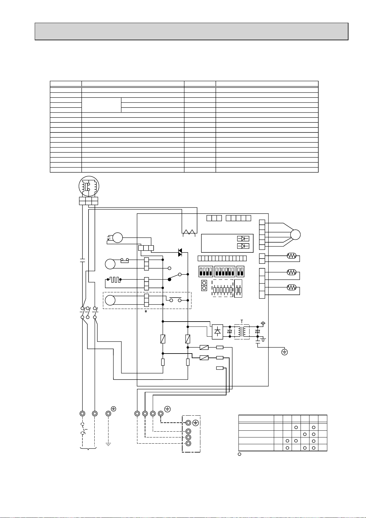
PU-P71VHA#2.UK PUH-P71VHA#2.UK PU-P100VHA#2.UK PUH-P100VHA#2.UK
PU-P71VHAR3.UK PUH-P71VHAR3.UK PU-P100VHAR3.UK PUH-P100VHAR3.UK
SYMBOL
MC
MF
TH3
TH4
TH6
C3
C5
CH
52C
21S4
63H
49C
TB1
LEV
JA, JB(O.B)
NAME SYMBOL
COMPRESSOR (INNER THERMOSTAT)
FAN MOTOR (INNER THERMOSTAT)
THERMISTOR
MF CAPACITOR
MC CAPACITOR
CRANKCASE HEATER
MC CONTACTOR
4-WAY VALVE SOLENOID COIL
HIGH PRESSURE PROTECT SWITCH
INNER THERMOSTAT FOR MC
TERMINAL BLOCK
LINER EXPANSION VALVE
JUMPER WIRE
49C
MC
A1 A2 B1
A1 A2 B1
S
C
R
R
W
B
C3
H
L
T
U
CH
6
/
T
3
52C
5
/
L
3
C5
E
D
2
/
T
1
1
/
L
1
LIQUID TEMP
DISCHARGE TEMP
2-PHASE PIPE TEMP
MF
63H
A1
52C
A2
21S4
BLU
RED
NAME
O.B
FUSE1 (O.B)
FUSE2 (O.B)
FUSE3 (O.B)
FUSE4 (O.B)
X51 (O.B)
X52 (O.B)
F.C (O.B)
SW1 (O.B)
SW4 (O.B)
SW5 (O.B)
J1~J6 (O.B)
T (O.B)
CT (O.B)
LED1 (O.B)
LED2 (O.B)
CN31 (O.B)
OUTDOOR CONTROLLER BOARD
FUSE (6.3A 250V)
FUSE (6.3A 250V)
FUSE (6.3A 250V)
FUSE (6.3A 250V)
MC/CH RELAY
21S4 RELAY
FAN CONTROLLER
GROUP NUMBER ADDRESS
TEST RUN
FUNCTION SELECTION
MODEL SELECTION
TRANSFORMER
CURRENT TRANS
OPERATION CHECK DISPLAY LED
OPERATION CHECK DISPLAY LED
EMERGENCY OPERATION CONNECTOR
+2
O.B
3 2 1
CNVMNT
(WHT)
X51
X52
F.C
CT
CNM
ON
OFF
FUSE1
1413121110
SW5
CN31
MF3
(WHT)
3
1
52C
1
(PNK)
33
CH
(BLU)
1
3
21S4
1
(GRN)
1
FUSE2
FUSE4
FUSE3
4/S
R
1 2 3 4 5
CNMNT
(WHT)
LED1 (GRN)
LED2 (RED)
9 8 7 6 5 4 3 2 1
J1J2J3J4J5
SW1
SW4
J6
+2
S1
S2
S3
CNVEV
(WHT)
(WHT)
TH3/TH6
JA
JB
(RED)
TH4
6 5 4 3 2 1
TH4
1 2
TH6
TH3
1 2 3 4
LEV
B
R
L
E
U
D
LN
TB1
POWER SUPPLY
~/N
230V 50Hz
Y
O
B
L
R
R
W
N
N
S3
S2
S1
S3
INDOOR
UNIT
S2
S1
TB4
+1 PUH-P71/P100VHA MODEL ONLY
+2 MODEL SELECTION
MODEL
PUH-P71VHA
PUH-P100VHA
PU-P71VHA
PU-P100VHA
: with jumper wire : without jumper wire
J1
J2
J4
J3
<Notes when servicing>
Some fastening terminals have a lock mechanism : When removing the fastening terminal, push the projection (locking lever) on the
terminal with your finger and pull it out.
21
J5 J6
Page 22
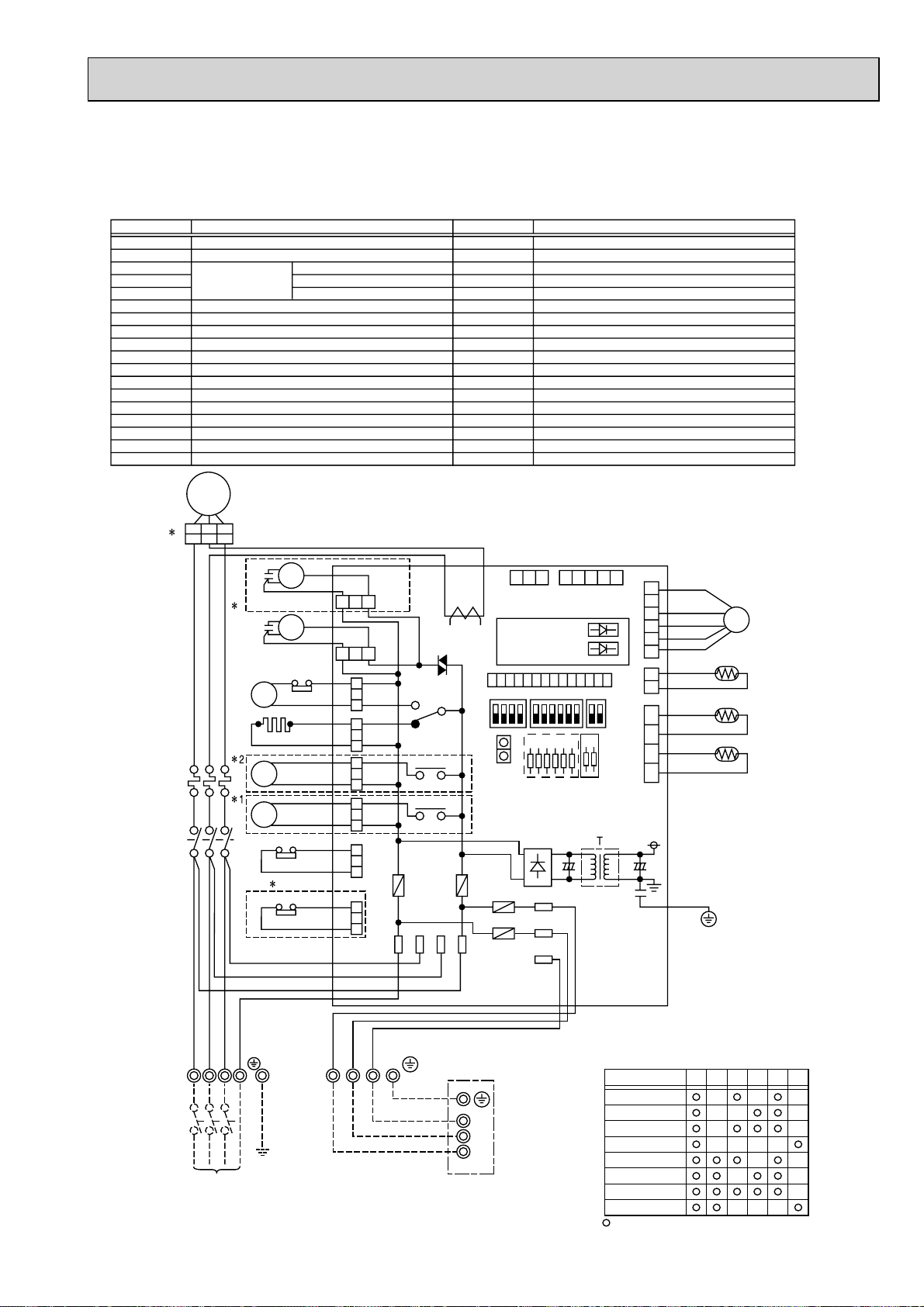
PU-P71YHA(1).UK PU-P100YHA(1).UK PU-P125YHA(1).UK PU-P140YHA(1).UK
PUH-P71YHA
(1).UK PUH-P100YHA(1).UK PUH-P125YHA(1).UK PUH-P140YHA(1).UK
SYMBOL
MC
MF
TH3
TH4
TH6
C3
C4
CH
52C
21S4
SV
63H
51C
TB1
LEV
TB2
63L
O.B
COMPRESSOR
FAN MOTOR(INNER THERMOSTAT)
THERMISTOR
MF CAPACITOR
MF CAPACITOR
CRANKCASE HEATER
MC CONTACTOR
4-WAY VALVE SOLENOID COIL
BYPASS VALVE SOLENOID COIL
HIGH PRESSURE PROTECT SWITCH
THERMAL RELAY
TERMINAL BLOCK
LINEAR EXPANSION VALVE
TERMINAL BLOCK
LOW PRESSURE PROTECT SWITCH
OUTDOOR CONTROLLER BOARD
NAME
LIQUID TEMP
DISCHARGE TEMP
COND./EVA.TEMP
SYMBOL
FUSE1(O.B)
FUSE2(O.B)
FUSE3(O.B)
FUSE4(O.B)
X51 (O.B)
X52 (O.B)
X53 (O.B)
F.C (O . B )
SW1 (O.B)
SW4 (O.B)
SW5 (O.B)
JA,JB(O.B)
JI~J6 (O.B)
T (O.B)
CT (O.B)
LED1 (O.B)
LED2 (O.B)
CN31 (O.B)
FUSE (6.3A 250V)
FUSE (6.3A 250V)
FUSE (6.3A 250V)
FUSE (6.3A 250V)
MC/CH RELAY
21S4 RELAY
SV RELAY
FAN CONTROLLER
GROUP NUMBER ADDRESS
TEST RUN
FUNCTION SELECTION
JUMPER WIRE
MODEL SELECTION +4
TRANSFORMER
CURRENT TRANS
OPERATION CHECK DISPLAY LED
OPERATION CHECK DISPLAY LED
EMERGENCY OPERATION CONNECTER
NAME
MC
A1A1A2A2B1
+
3
51C
TB1 TB2
<Notes when servicing>
Some fastening terminals have a lock mechanism:When removing the fastening terminal, push the projection(locking lever)on a terminal with
your finger and pull it out.
B1
U
V
W
C4
+1
R
E
D
2
/
T
1
C3
W
B
H
L
T
K
CH
4
6
/
/
T
T
2
3
+2
+1
52C
1
3
5
/
/
/
L
L
L
1
2
3
BLK
WHT
RED
R
W
B
B
E
H
L
L
D
T
K
U
L3NL2L1
POWER SUPPLY
3N~
400V 50Hz
52C
21S4
SV
51C
+1
MF
MF
a
b
63L
63H
13
13
Y
O
L
R
W
N
MF4
(WHT)
(WHT)
MF3
52
(PNK)
3131 31
CH
(BLU)
21S4
(GRN)
31
SV
(BLK)
51CM
(ORN)
3131
63L
(RED)
4/S T S R
B
R
N
S3S2S1
X51
X52
X53
FUSE2
F. C
CT
CNM
TB4
321 12345
CNVMNT
(WHT)
1011121314
SW5
ON
OFF
CN31
FUSE1
FUSE4
FUSE3
S3
INDOOR
UNIT
S2
S1
CNMNT
(WHT)
LED1(GRN)
LED2(RED)
SW1 SW4
J1J2J3J4J5J6JA
+4
S1
S2
S3
CNLEV
(WHT)
TH4
123456789
(WHT)
TH3/TH6
JB
(RED)
T
O.B
LEV
634
12 12 23145
+1 PU(H)-P125/140YHA MODEL ONLY
+2 PUH-P71/P100/P125/P140YHA MODEL ONLY
+3 PU(H)-P71/100YHA MODEL ONLY
+4 MODEL SELECTION
MODEL
PUH-P71YHA
PUH-P100YHA
PUH-P125YHA
PUH-P140YHA
PU-P71YHA
PU-P100YHA
PU-P125YHA
PU-P140YHA
TH4
TH6
TH3
J1 J2
: with jumper wire : without jumper wire
J3
J4
J5
J6
22
Page 23
PU-P71YHA#2.UK PU-P100YHA#2.UK PU-P125YHA#2.UK PU-P140YHA#2.UK
PUH-P71YHA#2.UK PUH-P100YHA#2.UK PUH-P125YHA#2.UK PUH-P140YHA#2.UK
PU-P71YHAR3.UK PU-P100YHAR3.UK PU-P125YHAR3.UK PU-P140YHAR3.UK
PUH-P71YHAR3.UK PUH-P100YHAR3.UK PUH-P125YHAR3.UK PUH-P140YHAR3.UK
SYMBOL
MC
MF
TH3
TH4
TH6
C3
C4
CH
52C
21S4
SV
63H
51C
TB1
LEV
TB2
63L
JA, JB(O.B)
NAME
COMPRESSOR
FAN MOTOR (INNER THERMOSTAT)
THERMISTOR
MF CAPACITOR
MC CAPACITOR
CRANKCASE HEATER
MC CONTACTOR
4-WAY VALVE SOLENOID COIL
BYPASS VALVE SOLENOID COIL
HIGH PRESSURE PROTECT SWITCH
THERMAL RELAY
TERMINAL BLOCK
LINER EXPANSION VALVE
TERMINAL BLOCK
LOW PRESSURE PROTECT SWITCH
JUMPER WIRE
LIQUID TEMP
DICHARGE TEMP
2-PHASE PIPE TEMP
MC
A1 A2 B1
3
A1 A2 B1
U
V
51C
W
R
W
B
E
H
L
D
T
K
4
2
6
/
/
/
T
T
T
2
1
3
52C
3
1
5
/
/
/
L
L
L
2
1
3
1
CH
BLK
WHT
RED
C4
C3
52C
21S4
SV
MF
MF
63H
A1
A2
51C
95
96
1
63L
3
1
3
1
131313131313
(PNK)
(BLU)
21S4
(GRN)
(BLK)
51CM
(ORN)
(RED)
MF4
(WHT)
(WHT)
MF3
52
X51
CH
X52
SV
63L
X53
FUSE2 FUSE1
4/S T S R
O.B
FUSE1 (O.B)
FUSE2 (O.B)
FUSE3 (O.B)
FUSE4 (O.B)
X51 (O.B)
X52 (O.B)
X53 (O.B)
F.C (O.B)
SW1 (O.B)
SW4 (O.B)
SW5 (O.B)
J1~J6 (O.B)
T (O.B)
CT (O.B)
LED1 (O.B)
LED2 (O.B)
CN31 (O.B)
CT
F.C
SYMBOL
CNM
ON
OFF
FUSE4
FUSE3
3 2 1
CNVMNT
(WHT)
LED1 (GRN)
LED2 (RED)
1413121110
SW5
CN31
OUTDOOR CONTROLLER BOARD
FUSE (6.3A 250V)
FUSE (6.3A 250V)
FUSE (6.3A 250V)
FUSE (6.3A 250V)
MC/CH RELAY
21S4 RELAY
SV RELAY
FAN CONTROLLER
GROUP NUMBER ADDRESS
TEST RUN
FUNCTION SELECTION
MODEL SELECTION
TRANSFORMER
CURRENT TRANS
OPERATION CHECK DISPLAY LED
OPERATION CHECK DISPLAY LED
EMERGENCY OPERATION CONNECTOR
NAME
+4
O.B
1 2 3 4 5
CNMNT
CNVEV
(WHT)
(WHT)
6 5 4 3 2 1
J6
TH3/TH6
JA
JB
(RED)
TH4
(WHT)
1 2
1 2 3 4
9 8 7 6 5 4 3 2 1
SW1 SW4
J1J2J3J4J5
+4
S1
S2
S3
LEV
TH4
TH6
TH3
R
W
B
B
E
H
L
D
T
L1NL2 L3
TB1
POWER SUPPLY
3N~
400V 50Hz
L
U
K
Y
L
W
TB2
S1 S2 S3
O
B
R
R
N
N
S3
INDOOR
UNIT
S2
S1
TB4
+1 PU(H)-P125/140YHA MODEL ONLY
+2 PUH-P71/P100/P125/P140YHA MODEL ONLY
+3 PU(H)-P71/100YHA MODEL ONLY
+4 MODEL SELECTION
MODEL
PUH-P71YHA
PUH-P100YHA
PUH-P125YHA
PUH-P140YHA
J1 J2
J3
PU-P71YHA
PU-P100YHA
PU-P125YHA
PU-P140YHA
: with jumper wire : without jumper wire
<Notes when servicing>
Some fastening terminals have a lock mechanism: When removing the fastening termina, push the projection (locking lever) on
the terminal with your finger and pull it out.
23
J6
J4
J5
Page 24
9 WIRING SPECIFICATIONS
9-1. FIELD ELECTRICAL WIRING (power wiring specifications)
Outdoor unit model
Outdoor unit Power supply
Outdoor unit input capacity
Main switch (Breaker)
Max. Permissive System Impedance ()
Outdoor unit power supply
)
2
Outdoor unit power supply earth
Indoor unit-Outdoor unit *2
Wiring
Indoor unit-Outdoor unit earth
Wire No. %
size (mm
Remote controller-Indoor unit *3
Outdoor unit L-N
Outdoor unit L1-N, L2-N, L3-N
Indoor unit-Outdoor unit S1-S2 *4
rating
Circuit
Indoor unit-Outdoor unit S2-S3 *4
Remote controller-Indoor unit *4
*1. A breaker with at least 3.0 mm contact separation in each pole shall be provided. Use earth leakage breaker (NV).
*2. Max. 45 m
*3. The 10 m wire is attached in the remote controller accessory.
*4. The figures are NOT always against the ground.
Notes: 1. Wiring size must comply with the applicable local and national code.
2
If 2.5 mm
used, Max. 50 m
2
used and S3 separated, Max. 80 m
If 2.5 mm
S3 terminal has DC 24 V against S2 terminal. However between S3 and S1, these terminals are NOT electrically insulataed by the transformer or other device.
2. Power supply cords and Indoor/Outdoor unit connecting cords shall not be lighter than polychloroprene sheathed flexible cord. (Design 60245 IEC 57)
3. Install an earth longer than other cables.
*1
*4
P71V P100V P71Y P100Y P125Y P140Y
~/N (single), 50 Hz, 230 V 3N~(3phase), 50 Hz, 400 V
32 A 16 A 25 A
0.06 0.23 0.22 0.14 0.12
2 % Min. 4 4 % Min. 1.5 4 % Min. 2.5
1 % Min. 4 1 % Min. 1.5 1 % Min. 2.5
3 % 1.5 (polar)
1 % Min. 1.5
2 % 0.3 (Non-polar)
AC 230 V
AC 230 V
DC 24 V
DC 12 V
Caution:
Do not push the contactor button (52C) on the outdoor unit, otherwise the compressor may be damaged.
Power supply
Isolator
3 poles isolator
A-Control
Outdoor Unit
S1
S2
S3
S1
S2
S3
A-Control
Indoor Unit
1:1 system Synchronized twin and triple system Electrical wiring
• Synchronized twin
Indoor
unit
S1
S2
S3
Outdoor
1
Remote
controller
2
Unit
power
supply
Earth leakage breaker
wiring circuit breaker or
isolating switch
unit
L
N
Indoor/outdoor
unit connection
cable
S1
S2
S3
Indoor
unit
S1
S2
S3
1
Remote
controller
2
Indoor
unit
1
2
S1
S2
S3
• Synchronized triple
Unit
power
supply
Earth leakage breaker
wiring circuit breaker or
isolating switch
Outdoor
unit
L
N
Indoor/outdoor
unit connection
cable
S1
S2
S3
Unit
power
supply
Earth leakage breaker
wiring circuit breaker or
isolating switch
24
Outdoor
unit
L
N
Indoor/outdoor
connection cable
S1
S2
S3
Indoor
unit
S1
S2
S3
1
2
Remote
controller
Indoor
unit
1
2
S1
S2
S3
Indoor
unit
1
2
S1
S2
S3
Page 25
.
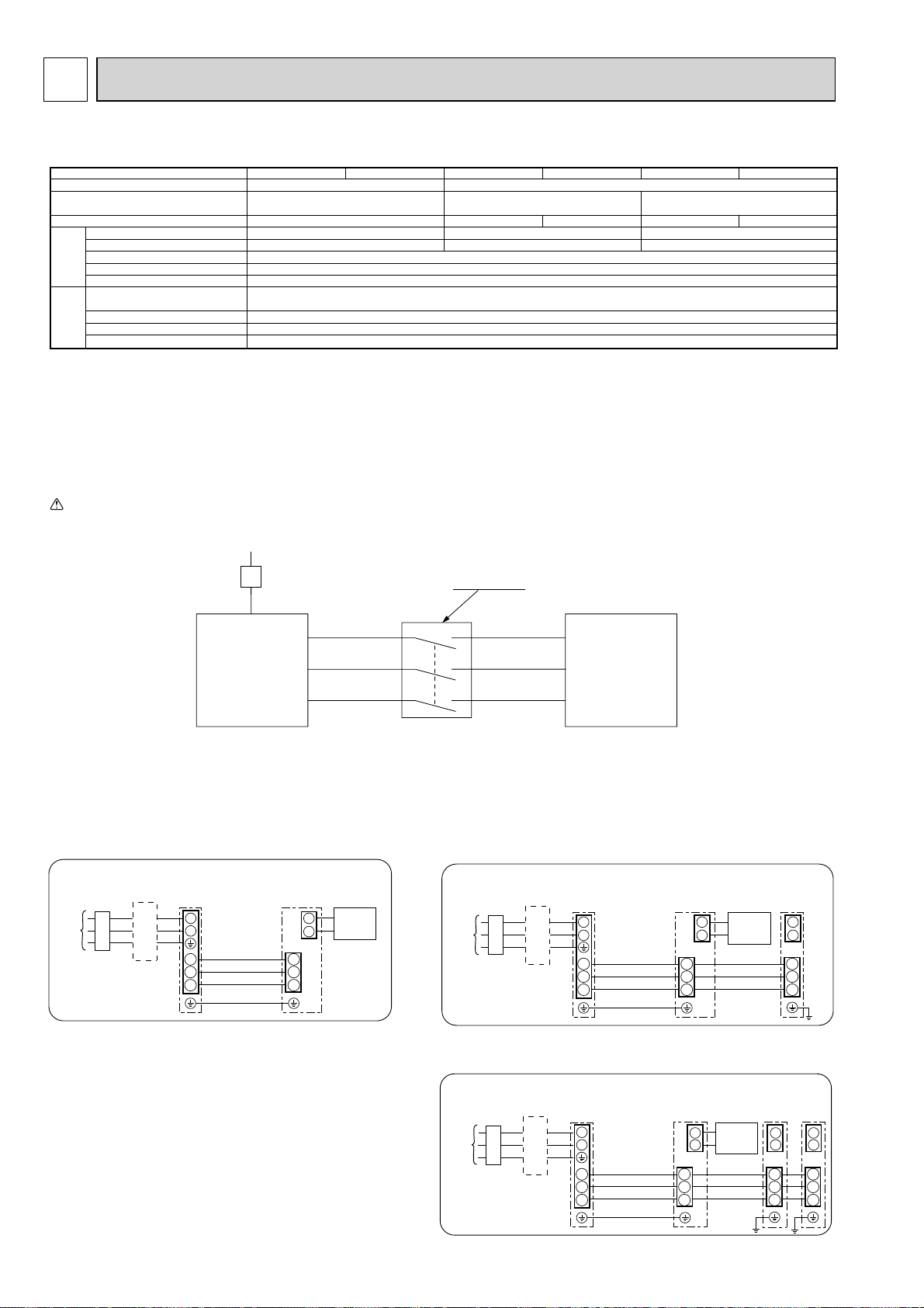
9-2. SEPARATE INDOOR UNIT/ OUTDOOR UNIT POWER SUPPLIES
The following connection patterns are available.
The outdoor unit power supply patterns vary on models.
1:1 System
<For models without heater>
* The optional indoor power supply terminal kit is required.
L
N
S1
S2
S3
L
N
S1
S2
S3
1
2
* Affix a label B that is included with the manuals near each wiring diagram for the indoor and outdoor units.
Simultaneous twin/triple system
<For models without heater>
* The optional indoor power supply terminal kits are required.
L
N
S1
S2
S3
L
N
S1
S2
S3
1
2
* Affix a label B that is included with the manuals near each wiring diagram for the indoor and outdoor units.
L
L
N
N
S1
S1
S2
S2
S3
S3
1
1
2
2
L
N
S1
S2
S3
1
2
Outdoor unit power supply
Earth leakage breaker
Wiring circuit breaker or isolating switch
Outdoor unit
Indoor unit/outdoor unit connecting cords
Remote controller
Indoor unit
Option
Indoor unit power supply
Outdoor unit power supply
Earth leakage breaker
Wiring circuit breaker or isolating switch
Outdoor unit
Indoor unit/outdoor unit connecting cales
Remote controller
Indoor unit
Option
Indoor unit power supply
Indoor unit earth
Indoor unit model
Indoor unit power supply
Indoor unit input capacity
Main switch (Breaker)
Indoor unit power supply
Indoor unit power supply earth
)
2
Indoor unit-Outdoor unit
(mm
Wiring
Indoor unit-Outdoor unit earth
Wire No. % size
Remote controller-Indoor unit *3
Indoor unit L-N *4
Indoor unit-Outdoor unit S1-S2 *4
Indoor unit-Outdoor unit S2-S3 *4
rating
Circuit
Remote controller-Indoor unit *4
*1
*2
RP35~140
~/N (single), 50 Hz, 230 V
16 A
2 % Min. 1.5
1 % Min. 1.5
2 % Min. 0.3
–
2 % 0.3 (Non-polar)
AC 230 V
–
DC24 V
DC12 V
*1. A breaker with at least 3 mm contact separation in each pole shall be provided. Use earth leakage breaker (NV).
*2. Max. 120 m
*3.The 10 m wire is attached in the remote controller accessory. Max. 500 m
*4.The figures are NOT always against the ground.
Notes: 1. Wiring size must comply with the applicable local and national code.
2. Power supply cords and indoor unit/outdoor unit connecting cords shall not be lighter than polychloroprene sheathed flexible cord
(Design 60245 IEC 57)
3. Install an earth longer than other cables.
If the indoor and outdoor units have separate power supplies, refer to the table
below. Change the indoor unit electrical box wiring referring to the figure in the
right and the Jumper wire JB settings of the outdoor unit control board.
Electric heater
(For models with
heater)
L
N
S1
S2
S3
Indoor unit power supplied from outdoor unit
(when shipped from factory)
Indoor unit electrical box connector
connection change
Label affixed near each wiring diagram
for the indoor and outdoor units
Outdoor unit jumper wire (when using
separate indoor unit/outdoor unit
power supplies only)
Indoor unit specifications
Required
Required
Jumper wire JB is cut.
* There are three types of labels (labels A, B, and C). Affix the appropriate labels to
the units according to the wiring method.
Please turn on the power supply of the outdoor unit first. Afterward, please turn on
the power supply of the indoor unit.
Connectors (connections when shipped
from the factory are for indoor unit power
supplied from outdoor unit)
BLUE
BLUE
YELLOW
YELLOW
ORANGE
CND
CND
Indoor unit
control board
Electric heater
(For models with
heater)
Separate indoor unit/outdoor unit power
supplies
L
N
S1
S2
S3
YELLOW
BLUE
If the indoor and
outdoor units have
separate power
supplies, change the
connections of the
connectors as shown
in the following
figure.
Connectors
BLUE
YELLOW
ORANGE
CND
CND
Indoor unit
control board
25
Page 26
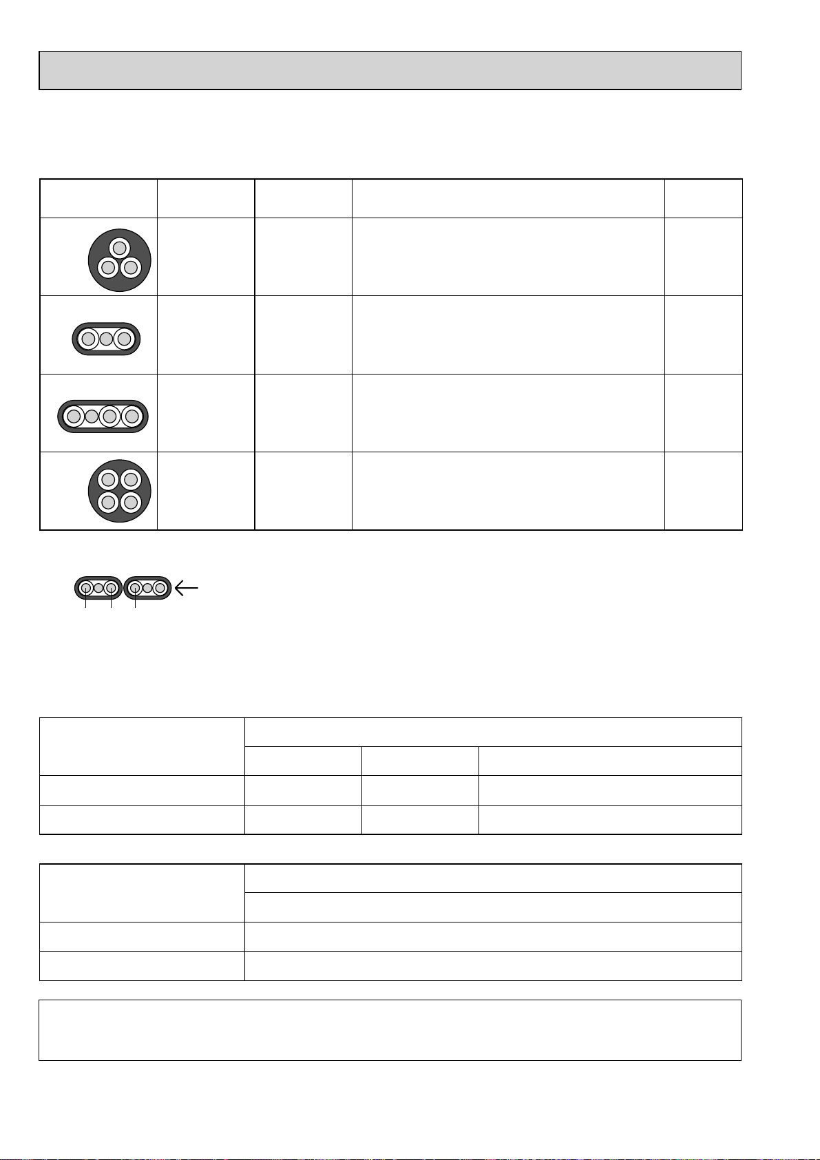
9-3. INDOOR – OUTDOOR CONNECTING CABLE
The cable shall not be lighter than design 60245 IEC or 227 IEC.
The cable length may vary depending on the condition of installation, humidity or materials, etc.
Cross section
of cable
Round
Wire size
2
(mm
)
2.5
Number
of wires
3
Polarity L(m) *5
Clockwise : S1-S2-S3
50
*1
Flat
2.5
Flat
1.5
Round
2.5
*1 : In case that cable with stripe of yellow and green is available.
*2 : In case that flat cables are connected as this picture, they can be used up to 80m.
3
4
4
Not applicable
(Because center wire has no cover finish)
From left to right : S1-Open-S2-S3
Clockwise : S1-S2-S3-Open
Connect S1 and S3 to the opposite angle
(3C Flat cable × 2)
S1 S2 S3
*3 : In case of regular polarity connection (S1-S2-S3), wire size is 1.5mm
*4 : In case of regular polarity connection (S1-S2-S3).
*5 : Mentioned cable length is just a reference value.
It may be different depending on the condition of installation, humidity or materials, etc.
2
.
Not
applicable
*2
45
*3
60
*4
Wire No. % Size ($)
Outdoor power supply
Max. 45m
Indoor unit-Outdoor unit
Indoor unit-Outdoor unit earth
+ The Max. cable length may vary depending on the condition of installation, humidity or materials, etc.
Indoor/Outdoor separate
power supply
Indoor unit-Outdoor unit
Indoor unit-Outdoor unit earth
3 % 1.5 (polar)
1 % Min. 1.5
Max. 50m
3 % 2.5 (polar)
1 % Min. 2.5
Wire No. % Size ($)
3 % 2.5 (polar) and S3 separated
Max. 120m
2 % Min. 0.3
—
Max. 80m
1 % Min. 2.5
+ The optional indoor power supply terminal kit is necessary
Be sure to connect the indoor-outdoor connecting cables directly to the units (no intermediate connections).
Intermediate connections can lead to communication errors if water enters the cables and causes insufficient insulation to
ground or a poor electrical contact at the intermediate connection point.
26
Page 27
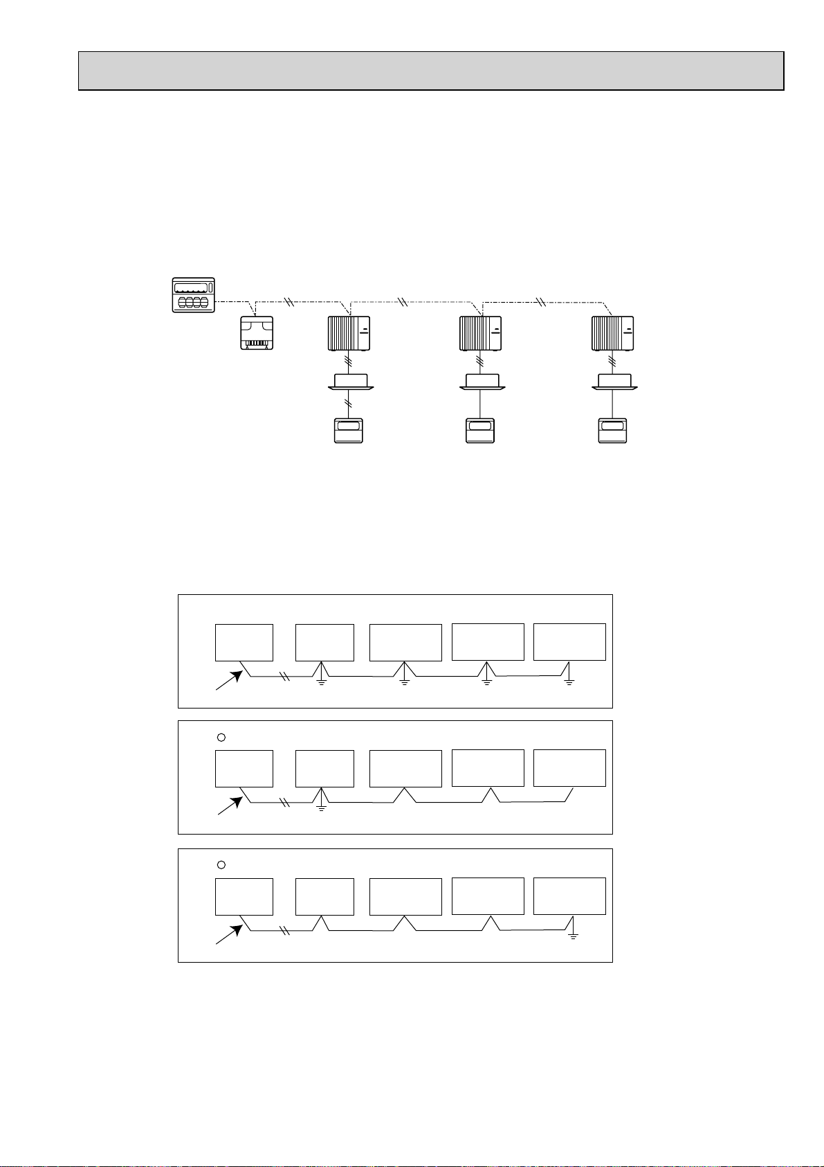
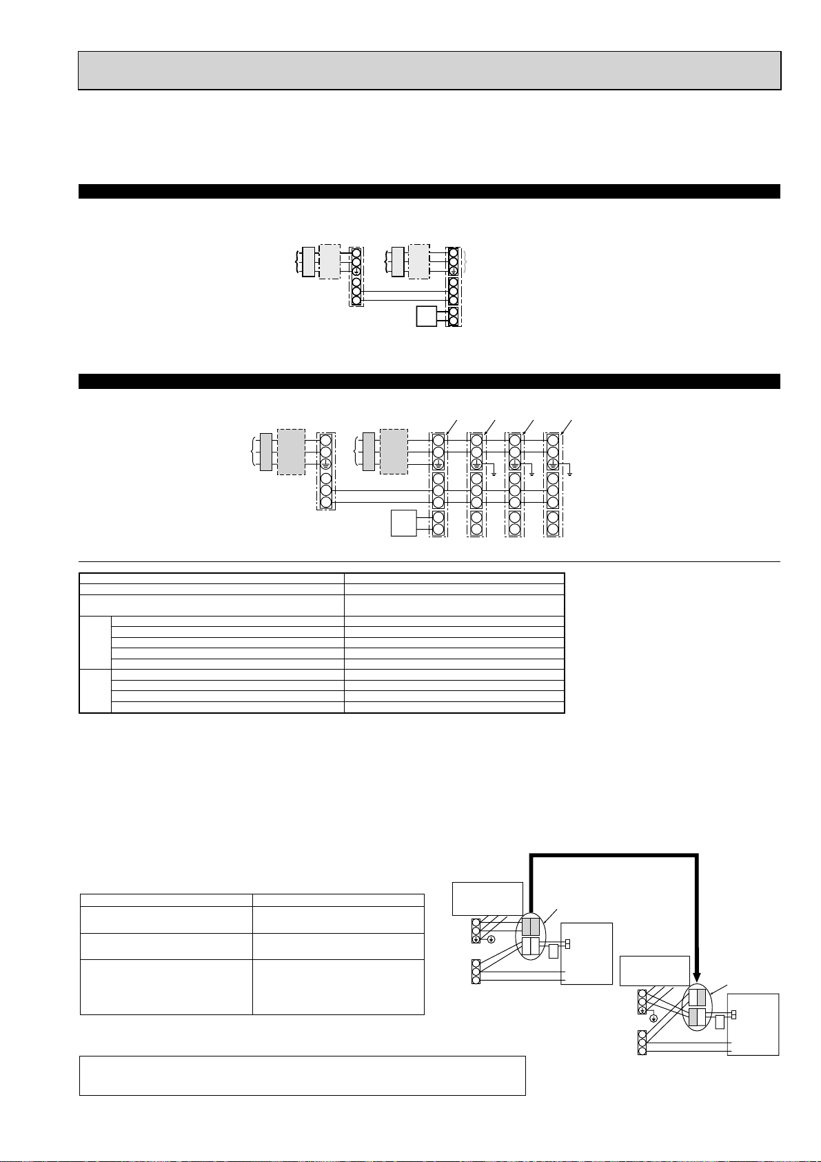
9-4. M-NET WIRING METHOD
(Points to note)
(1) Outside the unit, transmission wires should stay away from electric wires in order to prevent electromagnetic noise from
making an influence on the signal communication. Place them at intervals of more than 5cm. Do not put them in the same
conduit tube.
(2) Terminal block (TB7) for transmission wires should never be connected to 220~240V power supply. If it is connected,
electronic parts on M-NET P.C. board may be burn out.
(3) Use 2-core x 1.25mm
received normally if different types of transmission wires are put together in the same multi-conductor cable. Never do this
because this may cause a malfunction.
2
shield wire (CVVS, CPEVS) for the transmission wire. Transmission signals may not be sent or
A-control
remote
controller
Refrigerant
address 00
M-NET
address 03
Group
remote
controller
Power
supply
unit for
transmission
wire
A-control
remote
controller
Refrigerant
address 00
M-NET
address 01
A-control
remote
controller
Refrigerant
address 00
M-NET
address 02
It would be ok if M-NET wire (non-polar, 2-cores) is arranged in addition to the wiring for A-control.
(4) Earth only one of any appliances through M-NET transmission wire (shield wire). Communication error may occur due to
the influence of electromagnetic noise.
“Ed” error will appear on the LED display of outdoor unit.
“0403” error will appear on the central-control remote controller.
Bad example (Multi spot grounding of shield wire)
×
Central
remote
controller
Power
supply
appliance
M-NET type
outdoor unit
M-NET type
outdoor unit
M-NET type
outdoor unit
M-NET transmission wire
Good example 1 (Single spot grounding of shield wire)
Central
remote
controller
Power
supply
appliance
M-NET type
outdoor unit
M-NET type
outdoor unit
M-NET type
outdoor unit
M-NET transmission wire
Good example 2 (Single spot grounding of shield wire)
Central
remote
controller
Power
supply
appliance
M-NET type
outdoor unit
M-NET type
outdoor unit
M-NET type
outdoor unit
M-NET transmission wire
If there are more than two earthing spots on the shield wire, noise may enter into the shield wire because the earth wire
and shield wire form one circuit and the electric potential difference occurs due to the impedance difference among earth-
ing spots. In case of single spot earthing, noise does not enter into the shield wire because the earth wire and shield wire
do not form one circuit.
To avoid communication errors caused by noise, make sure to observe the single spot earthing method described in the
installation manual.
27
Page 28
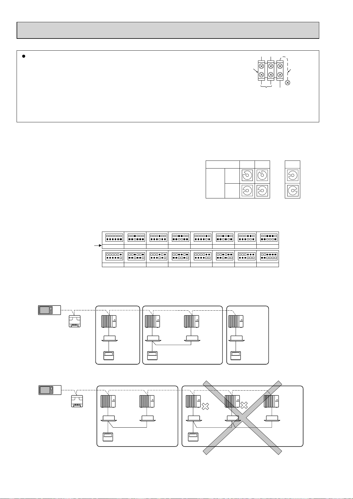
M-NET wiring
(1) Use 2-core × 1.25mm² shield wire for electric wires.
(Excluding the case connecting to system controller.)
M-NET
terminal
block
Earth
wire
(2) Connect the wire to the M-NET terminal block.Connect one core of the
transmission wire (non-polar) to A terminal and the other to B. Peel the
shield wire, twist the shield part to a string and connect it to S terminal.
(3) In the system which several outdoor units are being connected, the terminal
ABS
Transmission
wire
Shield
part
(A, B, S) on M-NET terminal block should be individually wired to the other
outdoor unit’s terminal, i.e. A to A, B to B and S to S.In this case, choose one of those outdoor units and drive a screw
to fix an ground wire on the plate as shown on the right figure.
9-4-1. M-NET address setting
In A-control models, M-NET address and refrigerant address should be set only for the outdoor unit. Similar to CITY MULTI
system, there is no need to set the address of outdoor unit and remote controller. To construct a central control system, the
setting of M-NET address should be conducted only upon the outdoor unit. The setting range should be 1 to 50 (the same as
that of the indoor unit in CITY MULTI system), and the address number should be consecutively set in a same group.
Address number can be set by using rotary switches
(SW11 for ones digit and SW12 for tens digit), which
is located on the M-NET board of outdoor unit.
(Initial setting: all addresses are set to “0”.)
<Setting example>
M-NET Address No.
SW11
Switch
setting
ones
digit
SW12
tens
digit
12
3
3
4
4
2
2
5
1
0
9
2
1
0
9
5
1
6
0
6
7
7
9
8
8
3
3
4
4
2
5
5
1
0
6
6
7
7
9
8
8
50
3
4
2
5
1
0
6
7
9
8
~
3
4
2
5
1
0
6
7
9
8
9-4-2. Refrigerant address setting
In case of multiple grouping system (multiple refrigerant circuits in one group), indoor units should be connected by remote
controller wiring (TB5) and the refrigerant address needs to be set. Leave the refrigerant addresses to “00” if the group setting is not conducted. Set the refrigerant address by using DIP SW1-3 to -6 on the outdoor controller board. [Initial setting: all
switches are OFF. (All refrigerant addresses are “00”.)]
Refrigerant
address
ON
OFF
1
ON
OFF
1
ON
OFF
1
3
4
5
2
6
0
ON
OFF
1
3
4
5
2
6
8
ON
OFF
1
3
4
5
2
6
1
ON
OFF
1
3
4
5
2
6
9
ON
OFF
1
3
4
5
2
6
2
ON
OFF
1
3
4
5
2
6
10
ON
OFF
1
3
4
5
2
6
3
ON
OFF
1
3
4
5
2
6
11
ON
OFF
1
3
4
5
2
6
4
ON
OFF
1
3
4
5
2
6
12
ON
OFF
1
3
4
5
2
6
5
ON
OFF
1
3
4
5
2
6
13
ON
OFF
1
3
4
2
6
3
4
2
14
3
5
5
4
5
2
6
ON
OFF
6
6
7
1
3
4
5
2
6
15
9-4-3. Regulations in address settings
In case of multiple grouping system, M-NET and refrigerant address settings should be done as explained in the above section. Set the lowest number in the group for the outdoor unit whose refrigerant address is “00” as its M-NET address.
Group A Group B Group C
System
controller
Power
supply
unit for
transmission
wire
Refrigerant
address 00
M-NET
address 01
A-control
remote
controller
w Refrigerant addresses can be overlapped if they are in the different group.
Group A Group B
System
controller
Power
supply
unit for
transmission
wire
Refrigerant
address 00
M-NET
address 01
A-control
remote
controller
Refrigerant
address 00
M-NET
address 02
A-control
remote
controller
Refrigerant
address 01
M-NET
address 02
Refrigerant
address 01
M-NET
address 03
TB5
TB5
A-control
remote
controller
Refrigerant
address 00
M-NET
address 04
Refrigerant
address 00
M-NET
address 04
A-control
remote
controller
Refrigerant
address 01
M-NET
address 03
Refrigerant
address 02
M-NET
address 05
w In group B, M-NET address of the outdoor unit whose refrigerant address is “00” is not set to the minimum in the group. As
“3” is right for this situation, the setting is wrong. Taking group A as a good sample, set the minimum M-NET address in the
group for the outdoor unit whose refrigerant address is “00”.
28
Page 29
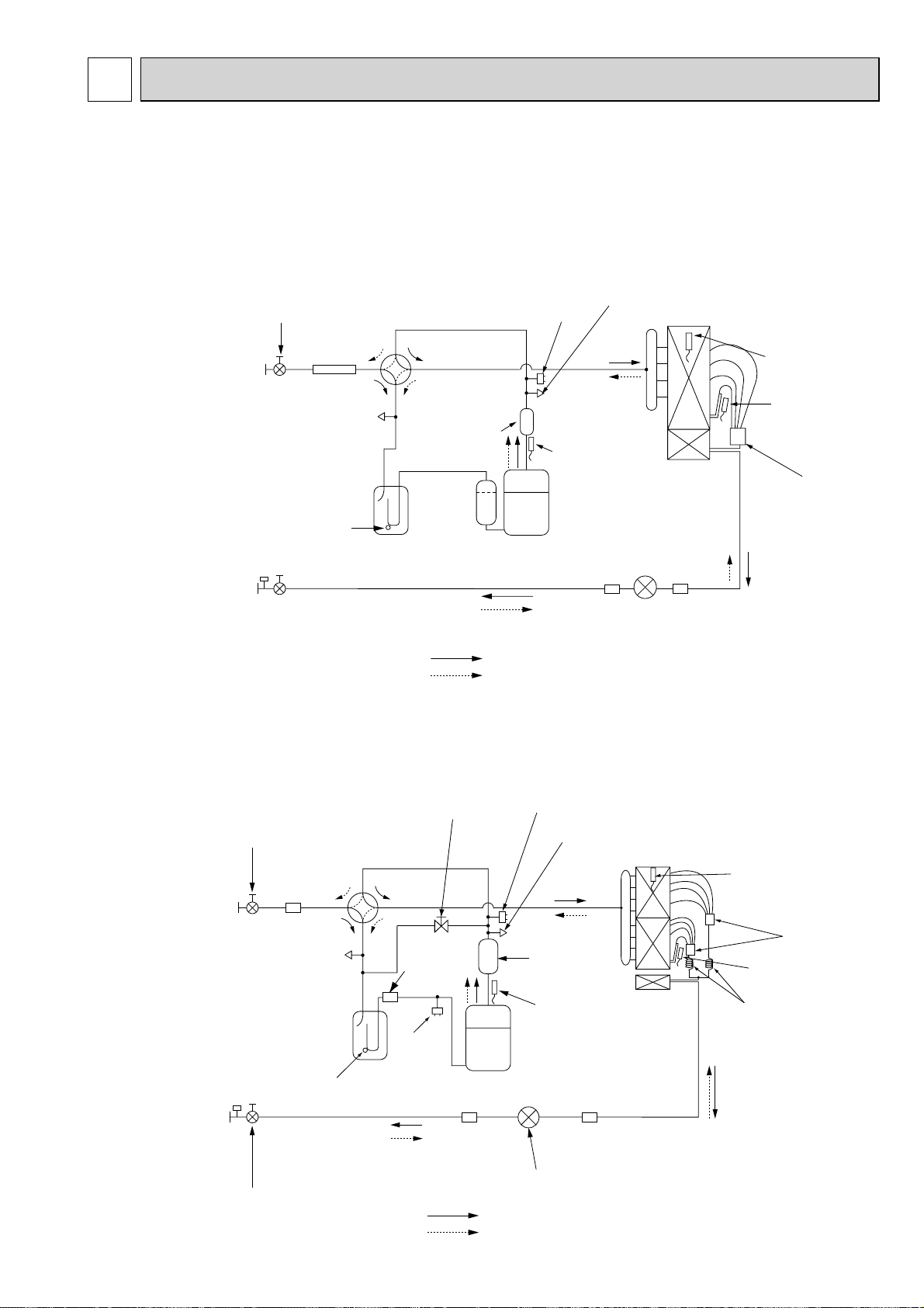
10 REFRIGERANT SYSTEM DIAGRAM
PUH-P71VHA(1).UK PU-P71VHA(1).UK PUH-P71YHA(1).UK PU-P71YHA(1).UK
PUH-P71VHA#2.UK PU-P71VHA#2.UK PUH-P71YHA#2.UK PU-P71YHA#2.UK
PUH-P71VHAR3.UK PU-P71VHAR3.UK PUH-P71YHAR3.UK PU-P71YHAR3.UK
PUH-P100VHA
PUH-P100VHA#2.UK PU-P100VHA#2.UK PUH-P100YHA#2.UK PU-P100YHA#2.UK
PUH-P100VHAR3.UK PU-P100VHAR3.UK PUH-P100YHAR3.UK PU-P100YHAR3.UK
Refrigerant GAS pipe
15.88 (W5/8")
(1).UK PU-P100VHA(1).UK PUH-P100YHA(1).UK PU-P100YHA(1).UK
Service port
Ball valve
Strainer
(#50)
4-way valve
High pressure
protect switch
(check)
Outdoor heat exchanger
Thermistor
(TH6)
Service
port
(check)
Accumulator
Muffler
Thermistor
(TH4)
Thermistor
(TH3)
Distributor
Strainer
(#40)
Refrigerant LIQUID pipe
9.52 (W3/8")
Stop valve
Compressor
(#100)
Strainer
(#100)
Strainer
Linear expansion valve
(with service port)
Refrigerant flow in cooling
Refrigerant flow in heating
PUH-P125YHA.UK PU-P125YHA.UK PUH-P125YHA1.UK PU-P125YHA1.UK
PUH-P140YHA.UK PU-P140YHA.UK PUH-P140YHA1.UK PU-P140YHA1.UK
PUH-P125YHA#2.UK PU-P125YHA#2.UK PUH-P140YHA#2.UK PU-P140YHA#2.UK
PUH-P125YHAR3.UK PU-P125YHAR3.UK PUH-P140YHAR3.UK PU-P140YHAR3.UK
Ball valve
Refrigerant GAS pipe
15.88 (W5/8")
Refrigerant LIQUID pipe
9.52 (W3/8")
(#50)
Strainer
Service
port
(check)
Accumulator
Strainer(#40)
Bypass valve
4-way
valve
Strainer
(#100)
Low
pressure
protect
switch
Compressor
Strainer
(#100)
High pressure protect switch
Service port (check)
Muffler
Thermistor
(TH4)
Strainer
(#100)
Thermistor
(TH6)
Distributor
Thermistor (TH3)
Capillary tube
(:4.0%:3.0-L200)%2
Stop valve
(with service port)
Linear expansion valve
Refrigerant flow in cooling
Refrigerant flow in heating
29
Page 30
11 TROUBLESHOOTING
11-1. TROUBLESHOOTING
<Error code display by self-diagnosis and actions to be taken for service (summary)>
Present and past error codes are logged and displayed on the wired remote controller and control board of outdoor unit.
Actions to be taken for service, which depends on whether or not the inferior phenomenon is reoccurring at service, are summarized in the table below. Check the contents below before investigating details.
Unit conditions at service
The inferior phenomenon is
reoccurring.
The inferior phenomenon is
not reoccurring.
Error code
Displayed
Not displayed
Logged
Not logged
Actions to be taken for service (summary)
Judge what is wrong and take a corrective action according
to “11-4. Self-diagnosis action table”.
Conduct trouble shooting and ascertain the cause of the
inferior phenomenon according to “11-5. Troubleshooting
by inferior phenomena”.
Consider the temporary defects such as the work of
protection devices in the refrigerant circuit including
compressor, poor connection of wiring, noise and etc.
Re-check the symptom, and check the installation
environment, refrigerant amount, weather when the
inferior phenomenon occurred, matters related to wiring
and etc.
Reset error code logs and restart the unit after finishing
service.
There is no abnormality concerning of parts such as
electrical component, controller board, remote controller
and etc.
Re-check the abnormal symptom.
Conduct trouble shooting and ascertain the cause of the
inferior phenomenon according to “11-5. Troubleshooting
by inferior phenomena”.
Continue to operate unit for the time being if the cause
is not ascertained.
There is no abnormality concerning of parts such as
electrical component, controller board, remote controller
and etc.
11-2. CHECK POINT UNDER TEST RUN
(1) Before test run
• After installation of indoor and outdoor units, piping work and electric wiring work, re-check that there is no refrigerant leak-
age, loosened connections and incorrect polarity.
• Measure impedance between the ground and the power supply terminal block (L, N) on the outdoor unit by 500V Megger
and check that it is 1.0M" or over.
wDo not use 500V Megger to indoor/outdoor connecting wire terminal block (S1, S2, S3) and remote controller terminal block
(1, 2). This may cause malfunction.
• Make sure that test run switch (SW4) is set to OFF before turning on power supply.
• Turn on power supply 12 hours before test run in order to protect compressor.
• For specific models which requires higher ceiling settings or auto-recovery feature from power failure, make proper changes
of settings referring to the description of “12. FUNCTION SETTING”.
Make sure to read operation manual before test run. (Especially items to secure safety.)
30
Page 31

"TEST RUN" and the currently selected
operation mode are displayed altemately.
Displays the remaining
test run time.
[TEST] button
Pipe (liquid) temperature
Operating procedures
1. Turn on the main power supply.
2. Press TEST button twice.
3. Press OPERATION SWITCH
button.
4. Press AIR DIRECTION button.
5. Check the outdoor unit fan for
correct running.
6. Press the ON/OFF button to reset the test run in progress.
7. Register the contact number.
While the room temperature display on the remote
controller is “PLEASE WAIT”, the remote controller is disabled.
Wait until “PLEASE WAIT” disappears before using remote controller.
“PLEASE WAIT” appears for about 2 minutes after power
supply is turned on. +1
The TEST RUN appears on the screen.
Cooling mode:
Heating mode: Check if warm air blows. (It takes a little
while until warm air blows.)
Check for correct motion of auto-vanes.
The outdoor unit features automatic capacity control to
provide optimum fan speeds. Therefore, the fan keeps
running at a low speed to meet the current outside air
condition unless it exceeds its available maximum power.
Then, in actuality, the fan may stop or run in the reverse
direction depending on the outside air, but this does not
mean malfunction.
Check if cool air blows and water is drained.
• In case of test run, the OFF timer will be activated, and the test run will automatically stop after two hours.
• The room temperature display section shows the pipe temperature of indoor units during the test run.
• Check that all the indoor units are running properly in case of simultaneous twin and triple operation. Malfunctions may not
be displayed regardless of incorrect wiring.
w1 After turning on the power supply, the system will go into startup mode, “PLEASE WAIT” will blink on the display section of
the room temperature, and lamp(green) of the remote controller will flash.
As to INDOOR BOARD LED, LED1 will be lit up, LED2 will either be lit up in case the address is 0 or turned off in case the
address is not 0. LED3 will blink.
As to OUTDOOR BOARD LED, LED1(green) and LED2(red) will light up. (After the startup mode of the system finishes,
LED2(red) will be turned off.)
In case OUTDOOR BOARD LED is digital display, — and — will be displayed alternately every second.
• If one of the above operations does not function correctly, the causes written below should be considered. Find causes from
the symptoms.
The below symptoms are under test run mode. “startup” in the table means the display status of w1 written above.
Symptoms in test run mode
Remote Controller Display
Remote controller displays “PLEASE
WAIT”, and
After power is turned on, “PLEASE WAIT”
is displayed for 3 minutes, then error code
is displayed.
No display appears even when remote
controller operation switch is turned on.
(Operation lamp does not light up.)
Display appears but soon disappears
even when remote controller is operated.
cannot be operated.
OUTDOOR BOARD LED Display
< > indicates digital display.
After “startup” is displayed, only
green lights up. <00>
After “startup” is displayed,
green(once) and red(once) blink
alternately. <F1>
After “startup” is displayed,
green(once) and red(twice) blink
alternately. <F3, F5, F9>
After “startup” is displayed,
green(twice) and red(once) blink
alternately. <EA. Eb>
After “startup” is displayed, only
green lights up. <00>
After “startup” is displayed, only
green lights up. <00>
• After power is turned on, “PLEASE WAIT” is displayed for 2
minutes during
• Incorrect connection of outdoor terminal block (L
S1, S2, S3.)
• Outdoor unit’s protection device connector is open.
• Incorrect wiring between the indoor and outdoor unit (Polarity
is wrong for S1, S2, S3.)
• Remote controller transmission wire short.
• There is no outdoor unit of address 0.
(Address is other than 0.)
• Remote controller transmission wire open.
• After canceling function selection, operation is not possible for
about 30 seconds. (Normal)
system startup. (Normal)
Cause
1, L2, L3 and
w Press the remote controller’s CHECK button twice to perform self-diagnosis. See the table below for the contents of LCD
display.
LCD
Abnormality of room temperature thermistor
P1
Abnormality of pipe temperature thermistor/Liquid
P2
Abnormality of drain sensor/Float switch connector open
P4
Drain overflow protection is working.
P5
Freezing/overheating protection is working.
P6
Abnormality of pipe temperature
P8
Abnormality of pipe temperature thermistor/Cond./Eva
P9
Abnormality of indoor controller board
Fb
Contents of inferior phenomena
LCD
Malfunction outdoor unit
U1~UP
Malfunction
F3~F9
E0~E5
Remote controller transmitting error
Indoor/outdoor unit communication error
E6~EF
No error history
---No applied unit
FFFF
Forced compressor stop (due to water leakage abnormality)
PA
Contents of inferior phenomena
outdoor unit
See the table below for details of the LED display (LED 1, 2, 3) on the indoor controller board.
(microprocessor power supply)
LED1
(remote controller)
LED2
(indoor/outdoor communication)
LED3
Lights when power is supplied.
Lights when power is supplied for wired remote controller.
The indoor unit should be connected to the outdoor unit with address "0" setting.
Flash when indoor and outdoor unit are communicating.
31
Page 32

N
N
,
ON/OFF
MODE
CHECK
TEST RUN
SET
TEST RUN
FAN
VAN E
LOUVER
RESET
CLOCK
TEMP
AUTO STOP
AUTO START
h
min
Test run [for wireless remote controller]
Measure an impedance between the power supply terminal block on
the outdoor unit and ground with a 500V Megger and check that it is
equal to or greater than 1.0M".
1 Turn on the main power to the unit.
2 Press the button twice continuously.
(Start this operation from the status of remote controller display
turned off.)
TEST RU
A and current operation mode are displayed.
3 Press the ( ) button to activate mode, then
check whether cool air is blown out from the unit.
4 Press the ( ) button to activate mode, then
check whether warm air is blown out from the unit.
5 Press the button and check whether strong air is blown out
from the unit.
6 Press the button and check whether the auto vane operates
properly.
7 Press the ON/OFF button to stop the test run.
Note:
• Point the remote controller towards the indoor unit receiver
while following steps 2 to 7.
• It is not possible to run the in FAN, DRY or AUTO mode.
TEST RU
MODE
MODE
FAN
VAN E
COOL
HEAT
(2) Outdoor Unit
1) Check Items
• After installation of indoor and outdoor units, and tubing and electric wiring work, check that the unit is free from leaks of refrigerant, loosened
connections, and incorrect polarity.
• Check that there is no negative phase and open phase. (The F1 message for negative phase and the F2 message for open phase will flash
at digital indicator LED 1 on the outdoor substrate. If this happens, rewire correctly.)
• Measure the impedance between power terminals (Single phase: L,N,;/ 3 phase: L1,L2,L3,;) and the ground with a 500V Megger and
check that it is 1.0M
door connection wiring terminals (S1,S2,S3) as this causes damage.
• When there is no error at the outdoor unit.
(If there is an error at the outdoor unit, it can be evaluated at LED 1 [digital display] of the outdoor substrate.)
• The stop valves are open both the liquid and gas sides.
After checking the above, execute the test run in accordance with the following.
2) Test run start and finish
• Operation from the indoor unit
Execute the test run using the installation manual for the indoor unit.
• Operation from the outdoor unit.
Execute settings for test run start, finish and operation mode (cooling, heating) using the DIP switch SW 4 on the outdoor substrate.
1 Set the operation mode (cooling, heating) using SW4-2.
2 Turn ON SW 4-1, The operation mode for SW 4-2 will be adhered to, and the test run will commence.
3 Turn OFF SW 4-1 to finish the test run.
• There may be a faint knocking noise emitted from the proximity of the fan during the test run. This is torque fluctuation occurring due to control of fan revolutions. There is no problem with the product.
Note:
The SW 4-2 operation mode cannot be changed during the test run. (To change run mode, stop the equipment with SW 4-1, change
the operation mode, then restart test run with SW 4-1.)
or more. Do not operate the equipment if measurement is less than 1.0m . *Never conduct this operation on the out-
SW4
(Initial setting)
ON
Stop
Cooling
Operation
12
Heating
32
Page 33

11-3. HOW TO PROCEED "SELF-DIAGNOSIS"
11-3-1. When a Problem Occurs During Operation
If a problem occurs in the air conditioner, the indoor and outdoor units will stop,
and the problem is shown in the remote controller display.
[CHECK] and the refrigerant address are displayed on the temperature
display, and the error code and unit number are displayed alternately as
shown below.
If the outdoor unit is malfunctioning, the unit number will be "00".
In the case of group control, for which one remote controller controls
multiple refrigerant systems, the refrigerant address and error code of the
unit that first experienced trouble (i.e., the unit that transmitted the error
code) will be displayed.
To clear the error code, press the
ON/OFF
button.
(Alternating Display)
Error code (2 or 4 digits)
Address (3 digits) or unit number (2 digits)
When using remote-/local-controller combined operation, cancel the error code after turning off remote operation. During
central control by a MELANS controller, cancel the error code by pressing the
ON/OFF
button.
11-3-2. Self-Diagnosis During Maintenance or Service
Since each unit has a function that stores error codes, the latest check code can be recalled even if it is cancelled by the remote
controller or power is shut off.
Check the error code history for each unit using the remote controller.
Switch to self-diagnosis mode.
Press the
will change as shown below.
CHECK
button twice within 3 seconds. The display content
Unit number or refrigerant address
to be diagnosed
Set the unit number or refrigerant address you want to diagnose.
Press the [TEMP] buttons ( and ) to select the desired number
or address. The number (address) changes between [01] and [50] or [00]
an d
[15].
The refrigerant address will begin to flash
approximately 3 seconds after being
selected and the self-diagnosis process will begin.
Display self-diagnosis results.
<When there is error code history>
(For the definition of each error code, refer to the indoor unit's installation manual or service handbook.)
(Alternating Display)
Error code (2 or 4 digits)
<When there is no error code history> <When there is no corresponding unit>
Address (3 digits) or unit number (2 digits)
Reset the error history.
Display the error history in the diagnosis result display screen (see step
).
33
Page 34

Press the
address or refrigerant address will flash.
Cancel self-diagnosis.
Self-diagnosis can be cancelled by the following two methods.
Press the
Press the
ON/OFF
CHECK
ON/OFF
button twice within 3 seconds. The self-diagnosis
button twice within 3 seconds. → Self-diagnosis will be cancelled and the screen will return to the previous state in effect before the start
button. → Self-diagnosis will be cancelled and the indoor unit will stop.
of self-diagnosis.
When the error history is reset, the display will look like the one shown below.
However, if you fail to reset the error history, the error content will be displayed again.
11-3-3. Remote Controller Diagnosis
If the air conditioner cannot be operated from the remote controller, diagnose the remote controller as explained below.
First, check that the power-on indicator is lit.
If the correct voltage (DC12 V) is not supplied to the remote controller, the
indicator will not light.
If this occurs, check the remote controller's wiring and the indoor unit.
Power on indicator
Switch to the remote controller self-diagnosis mode.
Press the
change as shown below.
CHECK
button for 5 seconds or more. The display content will
Press the
FILTER
button to start self-diagnosis.
Remote controller self-diagnosis result
[When the remote controller is functioning correctly]
Check for other possible causes, as there is no problem with the remote
controller.
[Where the remote controller is not defective, but cannot be operated.]
(Error display 2) [E3], [6833] or [6832] flashes.→ Transmission is not possible.
There might be noise or interference on the transmission path, or the indoor unit
or other remote controllers are defective. Check the transmission path and other
controllers.
[When the remote controller malfunctions]
(Error display 1) "NG" flashes. → The remote controller's transmitting-receiv-
The remote controller must be replaced with a new one.
(Error display 3)
The number of data errors is the difference between the number of bits sent from
the remote controller and the number actually transmitted through the transmission path. If such a problem is occurring, the transmitted data is affected by noise,
etc. Check the transmission path.
ing circuit is defective.
"ERC" and the number of data errors are displayed.
→ Data error has occurred.
When the number of data errors is "02":
Transmission data from remote controller
Transmission data on transmission path
To cancel remote controller diagnosis
Press the
approximately 30 seconds, the state in effect before the diagnosis will be restored.
CHECK
button for 5 seconds or more. Remote controller diagnosis will be cancelled, "PLEASE WAIT" and operation lamp will flash. After
34
Page 35

11-3-4. Malfunction-diagnosis method by wireless remote controller
<In case of trouble during operation>
When a malfunction occurs to air conditioner, both indoor unit and outdoor unit will stop and operation lamp blinks to inform
unusual stop.
<Malfunction-diagnosis method at maintenance service>
[Procedure]
CHECK
display
ON/OFF
button
CHECK
button
ON/OFF
MODE
CHECK
TEST RUN
SET
CHECK
FAN
VAN E
LOUVER
RESET
TEMP
AUTO STOP
AUTO START
CLOCK
h
min
Refrigerant
address
display
Temperature
button
HOUR
button
1. Press the CHECK button twice.
2. Press the temperature
buttons.
3. Point the remote controller at the
sensor to the indoor unit and
press the HOUR button.
• "CHECK" lights, and refrigerant
address "00" flashes.
• Check that the remote controller's
display has stopped before continuing.
• Select the refrigerant address of the
indoor unit for the self-diagnosis.
Note: Set refrigerant address using the
outdoor unit’s DIP switch (SW1).
(For more information, see the
outdoor unit installation manual.)
• If an air conditioner error occurs, the
indoor unit's sensor emits an intermit tent buzzer sound, the operation light
flashes, and the error code is
output.
(It takes 3 seconds at most for error
code to appear.)
4. Point the remote controller at the
sensor to the indoor unit and
press the ON/OFF button.
• The check mode is cancelled.
35
Page 36

• Refer to the following tables for details on the check codes.
[Output pattern A]
Beeper sounds
OPERATION
INDICATOR
lamp blink
pattern
Beep
Self-check
starts
(Start signal
received)
Beep Beep Beep Beep Beep Beep
1st2nd3
Off
Approx. 2.5 sec.On0.5 sec.On0.5 sec.On0.5 sec.
Number of blinks/beeps in pattern indicates the check
code in the following table (i.e., n=5 for “P5”)
rd
0.5 sec.
n
On
th
[Output pattern B]
Beeper sounds
OPERATION
INDICATOR
lamp blink
pattern
Beep Beep Beep Beep Beep Beep Beep
1st2nd3
Off
Self-check
starts
(Start signal
received)
Approx. 2.5 sec.OnApprox. 3 sec.On0.5 sec.On0.5 sec.On0.5 sec.On0.5 sec.
Number of blinks/beeps in pattern indicates the check
code in the following table (i.e., n=5 for “U2”)
[Output pattern A] Errors detected by indoor unit
Wireless remote controller
Wired remote controller
Beeper sounds/OPERATION
INDICATOR lamp blinks Check code
(Number of times)
1P1
2
P2 Pipe (TH2) sensor error
P9 Pipe (TH5) sensor error
3E6,E7
Intake sensor error
Indoor/outdoor unit communication error
4 P4 Drain sensor error/Float switch connector open
5
P5
PA
Drain pump error
Forced compressor stop
6 P6 Freezing/Overheating protection operation
7 EE Communication error between indoor and outdoor units
8 P8 Pipe temperature error
9 E4, E5 Remote controller signal receiving error
10
11
–
–
–
–
12 Fb Indoor unit control system error (memory error, etc.)
–
E0, E3
Remote controller transmission error
– E1, E2 Remote controller control board error
nd
1st2
Off
Approx. 2.5 sec.On0.5 sec.On0.5 sec.
Number of blinks/beeps in pattern indicates
the check code in the following table
rd
th
n
Off
Approx. 2.5 sec.OnApprox. 3 sec.On0.5 sec.On0.5 sec.
Symptom Remark
· · · Repeated
nd
1st2
Number of blinks/beeps in pattern indicates
the check code in the following table
· · · Repeated
As for indoor
unit, refer to
indoor unit's
service manual.
[Output pattern B]
Wireless remote controller
Beeper sounds/OPERATION
INDICATOR lamp blinks Check code
Errors detected by unit other than indoor unit (outdoor unit, etc.)
Wired remote controller
Symptom Remark
(Number of times)
1
2
3
4
5
6
7
8
9
10
11
12
13
14
E9
–
U3,U4
UF
U2
U1,Ud
–
–
U6
–
UH
–
–
UA, UE, UL
*1 If the beeper does not sound again after the initial
the OPERATION INDICATOR lamp does not come on,
Indoor/outdoor unit communication error
(Transmitting error) (Outdoor unit)
–
Open/short of thermistor(TH4/TH3) / Abnormal thermistor (TH6)
Compressor overcurrent interruption (When compressor locked)
Abnormal discharge temperature
Abnormal high pressure (63H worked)/Overheating protection.
(over-load operation protection / abnormal fan)
–
–
Compressor overcurrent interruption
–
Current sensor error
–
–
Thermal relay (51C) has been tripped/ Abnormal high pressure
(Ball valves close)/ Abnormal low pressure (63L worked)
2 beeps to confirm the self-check start signal was received and
there are no error records.
For details, check
the LED display
of the outdoor
controller board.
*2 If the beeper sounds 3 times continuously “beep, beep, beep (0.4 + 0.4 + 0.4 sec.)” after the initial 2 beeps to confirm
the self-check start signal was received, the specified refrigerant address is incorrect.
36
Page 37

11-4. SELF-DIAGNOSIS ACTION TABLE
<Abnormalities detected when the power is turned on>
Error Code
None —
Meaning of error code and detection method
1 No voltage is supplied to termi-
nal block (TB1) of indoor unit.
a) Power supply breaker is off.
b) Contact failure or discon-
nection of power supply
terminal
c) L1-phased open phase
2 Electric power is not charged
to power supply terminal of
controller board.
a) Contact failure of power
supply terminal
b) Disconnection of terminal R
or 4/S on controller board
3 Defective outdoor controller
board
a) Fuse 6.3A on controller
board is blown.
b) Defective parts
(Note 1) The number in ( ) is the error cord of upper remote controller (M-NET)
Case Judgment and action
1 Check following items.
a) Power supply breaker
b) Connection of power supply terminal block
(TB1)
c) Connection of power supply terminal block
(TB1)
2 Check following items.
a) Connection of power supply terminal block
(TB1)
b) Connection of terminal on controller board
3 Replace following items.
a) Fuse 6.3A
b) Controller board (When items above are
checked but the units can not be repaired)
F1
(4103)
F2
(4102)
F3
(5202)
F7
(4118)
F9
(4119)
Reverse phase detection, Power supply
and indoor/outdoor unit connecting wire
converse connection
1. 3 seconds after power on, judge reverse
phase by detecting voltage phase of
each phase.
2. Abnormal 4 minutes after power on if
power supply and indoor/outdoor unit
connecting wire have converse connection.
L3-phased open phase detection
Detect open phase 2 seconds after power
on.
63L connector open
Abnormal if 63L connector circuit is open
for 3 minutes continuously after power supply.
63L: Low-pressure switch
(PU(H)-P125, 140 only)
Reverse phase detector circuit
(controller board) fault
Abnormal if some of each phase detection
signal is not input 3 seconds after power
supply.
2 or more connectors open
Abnormal if two more out of connector (63L,
51CM) circuits are open for 3 minutes continuously after power on.
1 L1, L2, L3 are not connected
correctly.
2 Converse wiring of outdoor
power supply line (TB1) and
indoor power supply wire (TB4)
1 L3-phased open-phase
1 Disconnection or contact fail-
ure of 63L connector on outdoor controller board
2 Disconnection or contact fail-
ure of 63L
3 63L is working due to refrigerant
leakage or defective parts.
4 Defective outdoor controller
board
Defective outdoor controller
board
1 Disconnection or contact fail-
ure of connector (63L, 51CM)
on outdoor controller board
2 Disconnection or contact fail-
ure of (63L, 51C)
3 Defective (63L, 51C) (defective
parts)
4 Defective outdoor controller
board
1
• Check outdoor power supply connection (TB1)
• Replace two phases (for example phase L1
and phase L2) out of three phases of outdoor
power supply line (TB1)
2 Check wiring connection.
1 Check power supply.
1 Check connection of 63L connector on
outdoor controller board.
Refer to 11-7.
2 Check the 63L side of connecting wire.
3 Check refrigerant pressure.
Charge additional refrigerant.
Check continuity by tester.
Replace the parts if the parts are defective.
4 Replace outdoor controller board.
Replace outdoor controller board.
1 Check connection of (63L, 51CM)
connector on outdoor controller board.
Refer to 11-7.
2 Check the (63L, 51CM) side of
connecting wire.
3 Check continuity by tester.
Replace the parts if the parts are defective.
4 Replace outdoor controller board.
FA
(4108)
51CM connector open
Abnormal if 51CM connector circuit is open
for 3 minutes continuously after power on.
51CM: Thermal Relay
1 Disconnection or contact
failure of 51CM connector
on outdoor controller board
2 Disconnection or contact
failure of 51CM
3 Defective 51CM (defective
parts)
4 Defective outdoor controller
37
1 Check connecting wire.
2 Check connecting wire.
3 Check continuity by tester.
Replace the parts if the parts are defective.
4 Replace outdoor controller board.
Page 38

Error Code
EA
(6844)
Eb
(6845)
EC
(6846)
Ed
(0403)
Meaning of error code and detection method
Indoor/outdoor unit connector mis-wir-
ing, excessive number of units (5 units
or more)
1. Outdoor controller board can automatically check the number of connected
indoor units. Abnormal if the number of
connected indoor units can not be set
within 4 minutes after power on because
of mis-wiring of indoor/outdoor unit connecting wire and the like.
2. Abnormal if outdoor controller board
recognizes excessive number of indoor
unit.
Miswiring of indoor/outdoor unit connecting wire (converse wiring or disconnection)
Outdoor controller board can automatically
set the unit number of indoor units.
Abnormal if the indoor unit number can
not be set within 4 minutes after power on
because of miswiring (converse wiring or
disconnection) of indoor/outdoor unit connecting wire.
Start-up time over
The unit can not finish start-up process
within 4 minutes after power on.
Serial communication error
The communication between outdoor controller board and M-NET P.C. board is not
available.
1
2 Diameter or length of indoor/
3 Excessive number of indoor
4 Defective transmitting receiv-
5 Defective transmitting receiv-
6 Noise has entered into power
7 Remote controller is wired up
8 Two or more outdoor units has
(In case of group control).
1 Contact failure or mis-wiring of
2 Diameter or length of indoor/
4 Defective transmitting receiving
5 Defective transmitting receiving
6 Noise has entered into power
7 Remote controller is wired up
8 Two or more outdoor units has
(In case of group control).
9 Outdoor power supply board is
1 Contact failure of indoor/out-
2 Diameter or length of indoor/
6 Noise has entered into power
7 Remote controller is wired up
8 Two or more outdoor units has
(In case of group control).
1 Breaking of wire or contact
2 Contact failure of M-NET P.C.
3 Entrance of noise into trans-
4 Defective transmitting receiv-
5 Defective serial transmitting
Case
Contact failure or mis-wiring of
indoor/outdoor unit connecting wire.
outdoor unit connecting wire is
out of specified capacity.
units are connected to 1 outdoor unit. (5 units or more)
ing circuit of outdoor controller
board
ing circuit of indoor controller
board
supply or indoor/outdoor unit
connecting wire.
among indoor units (twin, triple
or quadro units).
refrigerant address “0.”
indoor/outdoor unit connecting
wire
outdoor unit connecting wire is
out of specified capacity.
circuit of outdoor controller board
circuit of indoor controller board
supply or indoor/outdoor unit
connecting wire.
among indoor units (twin, triple
or quadro units).
refrigerant address “0.”
defective.
door unit connecting wire
outdoor unit connecting wire is
out of specified capacity.
supply or indoor/outdoor unit
connecting wire.
among indoor units (twin, triple
or quadro units).
refrigerant address “0.”
failure of connector between
outdoor controller board and
M-NET P.C. board.
board power supply line
mission wire
ing circuit of M-NET P.C. board
receiving circuit of outdoor
controller board
1 Check disconnection or looseness or polar-
2 Check diameter and length of indoor/outdoor
Outdoor-indoor units’ interval: 50m maximum
Indoor-indoor units’ interval: 30m maximum
Also check if the connection order of flat
3 Check the number of indoor units that are
45 Turn the power off, and on again to check.
Replace outdoor controller board or indoor
Check the indoor/ outdoor unit connecting
6 Inspect transmission line to solve the problem.
7 Wire the remote controller to one of the mul-
8 Set the refrigerant address of outdoor units
9 Unless the wire has contact failure, discon-
w The descriptions above, 1-9, are for EA, Eb
1 Check disconnection, looseness, or breaking
2 Check departure or looseness of M-NET P.C.
3 Replace M-NET P.C. board.
4 Replace outdoor controller board.
Judgment and action
ity of indoor/outdoor unit connecting wire of
indoor and outdoor units.
unit connecting wire.
cable (VVF etc.) is S1, S2, S3.
connected to one outdoor unit. (If EA is
detected.)
controller board if abnormality is displayed
again.
wire.
tiple indoor units.
with different number starting from “0.”
nect CN2S on indoor power supply board to
measure the voltage. When CN2S does not
have a current of DC12V to DC16V, replace
the indoor power supply board.
and EC.
of connecting wire between outdoor controller board CN1 and M-NET P.C. board CN5.
board power supply line (CND-TB1).
38
Page 39

Error Code
U1
(1302)
Meaning of error code and detection method
Abnormal high pressure (High-pressure
switch 63H worked)
Abnormal if high-pressure switch 63H
worked (more than 4.14 MPa) during compressor operation.
63H: High-pressure switch
* Use current sensor to detect work or
return of 63H.
1 Short cycle of indoor unit
2 Clogged filter of indoor unit
3 Decreased airflow caused by
4 Dirt of indoor heat exchanger
5 Locked indoor fan motor
6 Malfunction of indoor fan motor
7 Defective operation of stop
8 Clogged or broken pipe
9 Locked outdoor fan motor
0 Malfunction of outdoor fan
1 Short cycle of outdoor unit
2 Dirt of outdoor heat exchanger
3 Disconnection or contact failure
4 Defective outdoor controller
5 Defective action of liner expan-
6 Refrigerant overcharge
Case
dirt of indoor fan
valve (Not full open)
motor
of 63H connection
board
sion valve
Judgment and action
1-6 Check indoor unit and repair defectives.
7 Check full open stop valve.
8 Check piping and repair defectives.
9-2 Check indoor unit and repair defectives.
3,4 Turn the power off and check UH display
when the power is turned on again.
Follow the UH display if UH is displayed.
5 Check linear expansion valve.
Refer to 11-6.
6 Replace refrigerant.
U1
Abnormal low current or open phase
• An extreme degradation of current value
causes abnormal stop.
• Abnormal if current detected phase
(V-phase) is open phase after first compressor start-up after supplying the power
by three phase power supply model.
• When compressor is operating, compressor is suspended under the following
condition: and when current detector (CT)
detects a current, which is lower than the
detected current specified in the table
below, under the following condition:
<Condition>
1 For PU/PUH-P71~P100V
Current detector (CT) has detected a
current, which is lower than the detected
current specified in the table below, for
0.7-0.8 second.
2 For PU/PUH-P71 ~ P140Y
Current detector (CT) has detected a
current, which is lower than the detected
current specified in the table below, for
0.4-0.5 second.
Model
P71V
P71Y,P100V,P100Y
P125Y
P140Y
Detected current
2.4 A
1.0 A
1.2 A
1.6 A
1 Shortage of refrigerant
2 Abnormal pressure degrada-
tion by pump down operation
3 V-phased open phase of com-
pressor
4 Abnormal compressor
Not abnormal if V is instantly
displayed when the main
power is off.
1 Check if refrigerant pressure is not degraded.
Check current of compressor operation when
2
abnormality occurred.
3 Check wiring of compressor.
4 Check or replace compressor.
U2
(1102)
U2
(1501)
Abnormal high discharging temperature
Abnormal if discharging temperature thermistor (TH4) exceeds following temperature during compressor operation.
Normal operation: 115:(P71-P100)/
125:(P125,P140)
or more for three min-
utes continuously or
135:
During defrosting: 135:
Abnormal shortage of refrigerant
Abnormal if intake super heat exceeds
following temperature during heating compressor operation.
70: or more, and indoor pipe <condenserevaporator> temperature (TH5) is 35: or
less.
1 Over-heated compressor
operation caused by shortage
of refrigerant
2 Defective operation of stop
valve
3 Defective thermistor
4 Defective outdoor controller
board
5 Defective action of linear
expansion valve
1 Leakage or shortage of refrig-
erant
2 Defective operation of stop
valve (not full open)
3 Defective thermistor (TH4,
TH5, TH6)
4 Defective outdoor controller
board
5 Defective action of electric
expansion valve
39
1 Check intake super heat.
Check leakage of refrigerant.
Charge refrigerant.
2 Check if stop valve is full open.
34
Turn the power off and check if U3 is displayed when the power is turned on again.
When U3 is displayed, refer to “Judgement
and action” for U3.
5 Check linear expansion valve.
Refer to 11-6.
1 Check leakage of refrigerant.
Charge refrigerant.
2 Check if stop valve is full open.
34 Turn the power off and check if U3 or U4 is
displayed when the power is put again.
When U3 or U4 is displayed, refer to
“Judgement and action” for U3 or U4.
6 Check linear expansion valve.
Refer to 11-6
Page 40

Error Code
U3
(5104)
Meaning of error code and detection method
Open/short circuit of discharging ther-
1 Disconnection or contact fail-
mistor (TH4)
Abnormal if open (0: or less) or short
(216: or more) is detected during compressor operation.
2 Defective thermistor
3 Defective outdoor controller
(Detection is inoperative for 5 minutes of
compressor starting process and for 10
minutes after defrosting.)
Case
ure of connector (TH4) on the
indoor controller board
board
Judgment and action
1 Check contact of connector (TH4) on the
indoor controller board.
Refer to 11-7
Check breaking of the lead wire for thermistor
(TH4). Refer to 11-6
2 Check resistance value of thermistor
(Refer to 11-6.), or check temperature by
microprocessor (Mode switch of SW2).
3 Replace outdoor controller board.
U4
(5105)
(5107)
U6
(4101)
UA
(4101)
Ud
(1504)
Open/short circuit of the liquid pipe
thermistor (TH3) or outdoor CondenserEvaporator pipe thermistor (TH6)
Abnormal if open (-39: or less) or short
(88: or more) is detected during compressor operation.
(Detection is inoperative for 7 minutes after
10 seconds of compressor starting and for
10 minutes after defrosting.)
Compressor over current (overload)
breaking
Abnormal if current value exceeds overload
set value during compressor operation.
P71V
P100V
P125Y
• • •
23.5A P71Y
• • •
28.5A P100Y
• • •
12.6A P140Y
• • •
7.8A
• • •
• • •
9.4A
15.6A
Thermal relay (51C) worked
Abnormal if 51C is open.
Over heat protection (over-load operation protection/abnormal fan)
Abnormal if pipe thermistor detects the
value that exceeds set value during compressor operation.
P71-P140
• • •
70:
1 Disconnection or contact failure
of connector (TH3/TH6) on the
indoor controller board
2 Defective thermistor
3 Defective outdoor controller
board
1 Gas pipe side ball valve and
liquid pipe side stop valve are
shut during operation.
2 Abnormal compressor
3 Abnormal power supply voltage
4 Overload operation
1 Ball valve and stop valve are
closed during operation.
2 Abnormal compressor
3 Abnormal power supply volt-
age
4 Short interruption.
1 In cooling mode: defective
outdoor fan (fan motor) or
short cycle of air path
2 Defective thermistor
3 Defective outdoor controller
board
1 Check contact of connector (TH3/TH6) on
the indoor controller board.
Refer to 11-7.
Check breaking of the lead wire for thermistor
(TH3/TH6). Refer to 11-6.
2 Check resistance value of thermistor
(Refer to 11-6.), or check temperature by
microprocessor (Mode switch of SW2).
3 Replace outdoor controller board.
1 Open ball valve and stop valve.
2 Check or replace compressor.
Refer to 6-2.
3 Check power supply voltage.
4 Check short cycle.
1 Open ball valve and stop valve.
2 Check or replace compressor.
Refer to 6-2.
3,4Check power supply voltage.
1 Check outdoor fan (fan motor)
Refer to 11-6.
24 Turn the power off and operate again to
check if U4 is displayed.
If U4 is displayed, follow the U4 processing
direction.
UE
(1302)
UL
(1300)
Abnormal High pressure
This error is detected (4.14MPa) from
63H action within 20 seconds of compressor starting in the first heating mode after
power on.
63H: high-pressure switch
Abnormal low pressure (63L worked)
Abnormal if connector (63L) is open (under-
0.03MPa) during compressor operation.
1 Gas pipe side ball valve and
liquid pipe side stop valve are
shut during operation.
2 Disconnection or contact failure
of 63H
3 Defective outdoor controller
board
4 Power supply reset is detected
while indoor filter clogs and
overload heating operation.
5 Defective outdoor controller
board
6 Defective action of linear
expansion valve
1 Gas pipe side ball valve and
liquid pipe side stop valve are
shut during operation.
2 Disconnection or contact fail-
ure of connector (63L) on outdoor controller board
3 Disconnection or contact fail-
ure of 63L
4 Defective outdoor controller
board
5 Leakage or defective of refrig-
erant
6 Defective action of linear
expansion valve
1 Open ball valve and stop valve.
23 Turn the power off, and operate again to
check if F5 is displayed.
If F5 is displayed, follow the F5 processing
direction.
4 Check indoor filter.
5 Replace outdoor controller board.
6 Check linear expansion valve.
Refer to 11-6.
1 Open ball valve and stop valve.
234 Turn the power off and on again to check
if F3 is displayed on restarting.
If F3 is displayed, follow the F3 process-
ing direction.
5 Leakage or defective of refrigerant
6 Check linear expansion valve
Refer to 11-6.
40
Page 41

Note: E1, E2 and E4 to E7, refer to indoor unit service manual.
Error Code
UF
(4100)
Meaning of error code and detection method
Compressor over current (start-up
locked) breaking
Abnormal if compressor current exceeds
1.2 times of overload set value.
1 Abnormal compressor
2 Clogged indoor filter
3 Open-phase compressor
Case
Judgment and action
1 Check compressor.
Refer to 6-2.
2 Check indoor unit and repair defective.
3 Check connection.
UH
(5300)
E0
(No display)
Current sensor error
Abnormal if compressor current is not
detected on first compressor start-up after
power supply is turned on.
Remote controller communication error
(Signal receiving error)
(1) Abnormal if any signal from IC of refrig-
erant address “0” could not normally
received for 3 minutes.
(2) Abnormal if sub remote controller could
not receive any signal for 2 minutes.
1 Disconnection or contact fail-
ure of connector (52C) on outdoor controller board
2 Disconnection or contact fail-
ure of coil 52C
3 Defective outdoor controller
board
4 Defective parts of 52C
5 Compressor V-phased wire
does not penetrate through
current detector.
1 Defective communication cir-
cuit of remote controller
2 Defective communication cir-
cuit of indoor controller board
of refrigerant address “0”
3 Noise has entered transmis-
sion wire of remote controller.
4 All remote controllers are set
as “sub” remote controller. In
this case, E4 is displayed at
outdoor LED, and E0 is displayed at remote controller.
5 Wiring regulations are not
observed.
• Length of wires
• Number of remote controllers
• Diameter of wires
• Number of indoor units
12 Check connection.
3 Replace outdoor controller board.
4 Check 52C.
5 Check wiring.
123 Diagnose remote controller
Dispose as follows according to diagno-
sis result.
a) When “RC OK” is displayed,
Remote controllers have no problem.
Turn the power off, and on again to
check. If, “PLEASE WAIT” is displayed
for 4 minutes or more, replace indoor
controller board.
b) When “RC NG” is displayed,
Replace remote controller.
c) When “RC E3” or “ERC 00-66” is dis-
played, noise may be causing abnormality.
4 Set one of the remote controllers “main”, if
outdoor LED is E4 while E0 is displayed at
remote controller.
E3
(No display)
E8
(6840)
E9
(6841)
Remote controller communication error
(Transmitting error)
(1) Abnormal if sub remote controller could
not find blank of transmission path for 6
seconds.
(2) Abnormal if remote controller could not
finish transmitting 30 times continuously.
Indoor/outdoor unit communication
error (Signal receiving error)
(Outdoor unit)
(1) Abnormal if outdoor controller could not
receive anything normally for 3 minutes.
Indoor/outdoor unit communication
error (Transmitting error)
(Outdoor unit)
(1) Abnormal if “0” receiving is detected 30
times continuously though indoor controller has transmitted “1”.
(2) Abnormal if outdoor controller could not
find blank of transmission path for 3
minutes.
1 Defective communication cir-
cuit of remote controller
2 Noise has entered transmis-
sion wire of remote controller.
3 Two or more remote control-
lers are set as "main."
1 Contact failure of indoor/out-
door unit connecting wire
2 Defective communication cir-
cuit of indoor controller board
3 Defective communication cir-
cuit of indoor controller board
4 Noise has entered indoor/ out-
door unit connecting wire.
1 Defective communication circuit
of outdoor controller
2 Noise has entered power supply.
3 Noise has entered indoor/
outdoor unit connecting wire.
4 Indoor/ outdoor unit connecting
wire has contact failure.
5 Defective communication circuit
between indoor and outdoor
unit on indoor controller board
1 Check disconnection or looseness of indoor/
outdoor unit connecting wire of indoor or outdoor units.
234 Turn the power off, and on again to
check. Replace indoor controller board
or outdoor controller board if abnormality
is displayed again.
123 Turn the power off, and on again to
check. Replace outdoor controller board
if abnormality is displayed again.
41
Page 42

Error Code
EF
(6607
or
6608)
Ed
(0403)
Meaning of error code and detection method
Not defined error code
This code is displayed when not defined
error code is received.
Serial communication error
Abnormal if communication between
outdoor controller circuit board and
M-NET board is not available.
1 Noise has entered transmis-
2 Noise has entered indoor/
outdoor unit connecting wire.
1 Breaking of wire or contact
failure of connector between
2 Contact failure of M-NET
3 Noise has entered into M-NET
Case
sion wire of remote controller.
outdoor controller circuit board
and M-NET board
board power supply line
transmission wire.
Judgment and action
12 Turn the power off, and on again to check.
Replace indoor controller board or outdoor
controller board if abnormality is displayed
again.
1 Check disconnection, looseness, or breaking of
connection wire between outdoor controller circuit board (CNMNT) and M-NET board (CN5).
2 Check disconnection, looseness, or breaking
of connection wire between outdoor controller
circuit board(CNMNT) and M-NET board (CND).
3 Check M-NET transmission wiring method.
<M-NET communication error>
Error Code
A0
(6600)
A2
(6602)
A3
(6603)
A6
(6606)
Meaning of error code and detection method
Address duplicate definition
This error is displayed when transmission
from the units of same address is detected.
Note) The address and attribute displayed
at remote controller indicate the controller that detected abnormality.
Hard ware error of transmission Pline
Transmission processor intended to transmit “0”, but “1” appeared on transmission
wire.
Note) The address and attribute display at
remote controller indicate the controller that detected abnormality.
BUS BUSY
1. Over error by collision damage
Abnormal if transmitting is not possible
for 8-10 minutes continuously because
of collision of transmission.
2. Data could not reach transmission wire
for 8-10 minutes continuously because
of noise or etc.
Note) The address and attribute displayed
at remote controller indicate the controller that detected abnormality.
Communication error with communication Pline
Defective communication between unit
processor and transmission processor
Note) The address and attribute display at
remote controller indicate the controller that detected abnormality.
(Note) “Indoor unit” in the text indicates M-NET P.C. board in outdoor unit.
Case Judgment and action
1 There are two or more same
address of controller of outdoor unit, indoor unit, FRESH
MASTER, or LOSSNAY.
2 Noise has entered into trans-
mission signal and signal was
transformed.
1 Error is detected if waveform is
transformed when wiring works
of transmission wire of outdoor unit, indoor unit, FRESH
MASTER or LOSSNAY are
done, or polarity is changed
with the power on and transmission data collide each
other.
2
Defective transmitting receiving
circuit of transmission processor
3 Transmission data is changed
by the noise on transmission.
1 Transmission processor could
not transmit because short
cycle voltage of noise and the
like have entered into transmission wire continuously.
2 Transmission quantity has
increased and transmission
is not possible because there
was wiring mistake of terminal
block for transmission wire
(TB3) and terminal block for
central control (TB7) in outdoor
unit.
3 Transmission are mixed with
others and occupation rate
on transmission wire rose
because of defective repeater
(a function to connector or
disconnect transmission of
control and central control
system) of outdoor unit, then
abnormality is detected.
1 Data of transmission proces-
sor or unit processor is not
transmitted normally because
of accidental trouble such as
noise or thunder surge.
2 Address forwarding from unit
processor is not transmitted
normally because of defective
transmission processor hardware.
Search the unit with same address as abnormality occurred. If the same address is found,
shut of the power supply of outdoor unit and
indoor unit and FRESH MASTER or LOSSNAY
at the same time for 2 minutes or more after
the address is corrected, and turn the power on
again.
Check transmission waveform or noise on
transmission wire.
1 If the works of transmission wire is done
with the power on, shut off the power supply
of outdoor unit and indoor unit and FRESH
MASTER or LOSSNAY at the same time for
2 minutes or more, and turn the power on
again.
2 Check transmission waveform or noise on
transmission wire.
1 Check if transmission wire of indoor unit,
FRESH MASTER, LOSSNAY, or remote
controller is not connected to terminal block
for central control (TB7) of outdoor unit.
2 Check if transmission wire of indoor unit,
FRESH MASTER or LOSSNAY is not
connected to terminal block for transmission
wire of outdoor unit.
3 Check if terminal block for transmission wire
(TB3) and terminal block for central control
(TB7) is not connected.
4 Check transmission waveform or noise on
transmission wire.
Turn off the power supply of outdoor unit and
indoor unit and FRESH MASTER or LOSSNAY
at the same time for 2 minutes or more, and put
the power on again. System returns normally if
abnormality was accidental malfunction. If the
same abnormality generates again, abnormality-generated controller may be defective.
42
Page 43

Error Code
A7
(6607)
Meaning of error code and detection method
NO ACK
1. Transmitting side controller detects
abnormal if a message was transmitted
but there is no reply (ACK) that a message was received. Transmitting side
detects abnormality every 30 seconds,
six times continuously.
Note) The address and attribute displayed
at remote controller indicate the controller that did not reply (ACK).
2. If displayed address or attribute is outdoor unit, indoor unit detects abnormality
when indoor unit transmitted to outdoor
unit and there was no reply (ACK).
3. If displayed address or attribute is indoor
unit, remote controller detects abnormality when remote controller transmitted to
indoor unit and there was no reply (ACK).
Common factor that has no relation with abnormality source.
1 The unit of former address
2 Extinction of transmission wire
3 Extinction of transmission wire
4 Extinction of transmission wire
voltage and signal is caused by
over-numbered units.
5 Accidental malfunction of
6 Defective of abnormality-gen-
1 Contact failure of transmission
2 Disconnection of transmission
3 Defective transmitting receiving
1 During group operation with
2 Contact failure of transmission
3 Disconnection of transmission
4 Defective trnamsitting receiving
Case Judgment and action
does not exist as address
switch has changed while the
unit was energized.
voltage and signal is caused
by over-range transmission
wire.
• Maximum distance
Remote controller line
•
voltage and signal is caused
by type-unmatched transmission wire.
.....
Type
With shield wire CVVS, CPEVS
With normal wire (no shield) VCTF, VCTFK, CVV
CVS, VVR, VVF, VCT
Diameter
abnormality-detected controller
(noise, thunder surge)
erated controller
wire of outdoor unit or indoor
unit
connector (CN2M) of outdoor
unit
circuit of outdoor unit or indoor
unit
indoor unit of multi- refrigerant
system, if remote controller
transmit to indoor unit while
outdoor unit power supply of
one refrigerant system is off
or within 2 minutes of restart,
abnormality is detected.
wire of remote controller or
indoor unit
connector (CN2M) of indoor
unit
circuit of indoor unit or remote
controller
.....
.......
200m
....
(12m)
1.25mm2 or more
Always try the followings when the error
“A7” occures.
1 Turn off the power supply of outdoor
unit, indoor unit,and FRESH MASTER or
LOSSNAY at the same time for 2 minutes or
more, and turn the power on again. If malfunction was accidental, the unit returns to
normal.
2 Check address switch of abnormality-gener-
ated address.
3 Check disconnection or looseness of abnor-
mality-generated or abnormality-detected
transmission wire (terminal block and connector).
4 Check if tolerance range of transmission wire
is not exceeded.
5 Check if type of transmission wire is correct
or not.
If there were some troubles of 1-5 above,
repair the defective, then turn off the power
supply of outdoor unit and indoor unit and
FRESH MASTER or LOSSNAY at the same
time for 2 minutes or more, and turn the power
on again.
• If there was no trouble with 1-5 above in
single refrigerant system (one outdoor unit),
controller of displayed address or attribute is
defective.
• If there was no trouble with 1-5 above in dif-
ferent refrigerant system (two or more outdoor
units), judge with 6.
6 If address of abnormality source is the
address that should not exist, there is the
unit that memorizes nonexistent address
information. Delete useless address information with manual setting function of remote
controller.
Only the system FRESH MASTER or
LOSSNAY are connected to, or the system
that is equipped with group setting of different refrigerant system.
If there was no trouble with 1-6 above, replace
the controller board of displayed address or
attribute.
If the unit does not return normally, multi-controller board of outdoor unit may be defective
(repeater circuit).
Replace multi-controller board one by one to
check if the unit returns normally.
4. If displayed address or attribute is
remote controller, indoor unit detects
abnormality when indoor unit transmitted
to remote controller and there was no
reply (ACK).
1 During group operation with
indoor unit of multi- refrigerant
system, if indoor unit transmit to remote controller while
outdoor unit power supply of
one refrigerant system is off
or within 2 minutes of restart,
abnormality is detected.
2 Contact failure of transmission
wire of remote controller or
indoor unit
3 Disconnection of transmission
connector (CN2M) of indoor
unit
4 Defective trnamsitting receiving
circuit of indoor unit or remote
controller
Continued to the next page.
43
Page 44

From the previous page.
Error Code
A7
(6607)
A8
(6608)
Meaning of error code and detection method
5. If displayed address or attribute is
FRESH MASTER,
Indoor unit detects abnormality when
indoor unit transmitted to FRESH
MASTER and there was no reply (ACK).
6. If displayed address or attribute is
LOSSNAY,
Indoor unit detects abnormality when
indoor unit transmitted to LOSSNAY and
there was no reply (ACK).
7. If displayed address or attribute is nonexistent
M-NET•NO RESPONSE
Abnormal if a message was transmitted
and there were reply (ACK) that message
was received, but response command
does not return. Transmitting side detects
abnormality every 30 seconds, six times
continuously.
Note) The address and attribute displayed
at remote controller is indicate the
controller that did not reply (ACK).
Case Judgment and action
1 During sequential operation
of indoor unit and FRESH
MASTER of other refrigerant
system, if indoor unit transmits
to FRESH MASTER while
outdoor unit power supply
of same refrigerant system
with FRESH MASTER is off
or within 2 minutes of restart,
abnormality is detected.
2 Contact failure of transmission
wire of indoor unit or FRESH
MASTER
3 Disconnection of transmission
connector (CN2M) of indoor
unit or FRESH MASTER
4 Defective transmitting receiving
circuit of indoor unit or FRESH
MASTER
1 If the power supply of
LOSSNAY is off, indoor unit
detects abnormality when it
transmits to LOSSNAY.
2 During sequential operation
of indoor unit and LOSSNAY
of other refrigerant system,
if indoor unit transmits to
LOSSNAY while outdoor unit
power supply of same refrigerant system with LOSSNAY
is off or within 2 minutes of
restart, abnormality is detected.
3 Contact failure of transmis-
sion wire of indoor unit of
LOSSNAY
4 Disconnection of transmission
connector (CN2M) of indoor
unit
5 Defective transmitting receiv-
ing circuit of indoor unit or
LOSSNAY
1 The unit of former address
does not exist as address
switch has changed while the
unit was energized.
2 Abnormality is detected
when indoor unit transmitted because the address
of FRESH MASTER and
LOSSNAY are changed after
sequential operation of FRESH
MASTER and LOSSNAY by
remote controller.
1 Transmitting condition is
repeated fault because of
noise and the like.
2 Extension of transmission wire
voltage and signal is caused by
over-range transmission wire.
• Maximum distance
•
Remote controller line
3 Extension of transmission wire
voltage and signal is caused
by type-unmatched transmission wire.
.....
Type
With shield wire CVVS, CPEVS
With normal wire (no shield) VCTF, VCTFK, CVV
CVS, VVR, VVF, VCT
Diameter.....1.25mm
4 Accidental malfunction of
abnormality-generated
controller
........
200m
....
(12m)
2
or more
Same as mentioned in “A7” of the previous
page
1 Check transmission waveform or noise on
transmission wire.
2 Turn off the power supply of outdoor unit
and indoor unit and FRESH MASTER or
LOSSNAY at the same time for 2 minutes or
more, and turn the power on again. If malfunction was accidental, the unit returns to
normal. If the same abnormality generates
again, controller of displayed address and
attribute may be defective.
44
Page 45

11-5. TROUBLESHOOTING BY INFERIOR PHENOMENA
Phenomena Factor Countermeasure
(1) Remote controller display does not
work.
(Electric current marker “ ” is not
displayed on the remote controller.)
Indoor control P.C. board LED
LED1
off off off
1
Lighting off
2
Lighting
3
(2) Remaining “PLEASE WAIT” display
on the remote controller
(3) When pressing the remote controller
operation switch the OPERATION
display is appeared but it will be
turned off soon.
(4) Even controlling by the wireless
remote controller no beep and not
working (Display is available on the
wireless remote controller.)
(5) When operating by the wireless
remote controller, beep sound is
heard without working.
(6) Upward/downward vane perform-
ance fault
LED2 LED3
(or blinking)
Blinking
(or lighting)
off
–
1 Main power is not turned on. (Power supply inferior)
2 Mis-wiring, breaking or contact failure of the connect-
1 Refrigerant address excepts “0”
2 Mis-wiring, breaking or contact failure of the connect-
1 Short circuit, miswiring and breaking
1 At longest 2 minutes after the power supply “PLEASE
1 Communication fault between the remote controller
2 Communication fault between the indoor and outdoor
3 Outdoor unit protection device is opened.
(Abnormal code will be displayed after 2~6 minutes.)
1 After cancelling to select function from the remote
1 The pair number settings of the wireless remote
controller and indoor control PCB are mismatched
2 Disconnecting of wireless receiving board and con-
3 Factor of the above (1)
1 No operation for max. 2 minutes after the power sup-
2 Remote operation is prohibited.
3 Factor of the above (2)
1 When the unit is as follows in the HEAT mode, the
(Working of COOL protection function)
2 When setting the downward vane in the cool/dry
3 Vane motor does mot rotate.
4 Standard position reading fault (Vane motor does not
Reference (Meaning of the indoor control board LED)
LED1 : Microprocessor power supply
....Display of DC14V is supply or not from indoor power.
LED2 : Power output supplied to remote controller
....Displays the power condition supplied to wired remote controller. When the
refrigerant address is “0” supplied power output ON.
LED3 : Indoor outdoor communication monitor
....Blinking, when receiving the signal normally from the outdoor unit.
ing line
ing line
WAIT” is displayed to start up.
and indoor
controller, the remote controller operation switch will
be not accepted for approx 30 seconds.
tact failure
ply ON
• Remote controlling adaptor is connected to the
indoor controller board (CN32).
• Remote operation is prohibited by centralised controller etc. since it is connected to MELANS.
vane is not downward.
• During HEAT preparation
• During defrosting
• During compressor stop
mode, the vane changes to Horizontal position after
1 hour
A) Vane motor fault
B) Disconnecting, breaking and contact fault of the
connector
C) Setting to no vane unit
stop.)
A) Limited switch fault
B) Disconnecting breaking and contact fault of the
connector
w Only AC timing motor adopting mode (No limited
switch for stepping motor adopting model)
1
Check the power wiring to the outdoor unit and the breaker.
2
Check for incorrect wiring, wiring breaks and poor connections between the indoor and outdoor units.
1
Set the refrigerant address to "0" (only 1 refrigerant can be
"0" for group control).
2
Check for incorrect wiring, wiring breaks and poor connections between the indoor and outdoor units.
Check for shorts, incorrect wiring and wiring breaks in the
1
remote controller wires.
2
Replace the remote controller if the voltage to the remotecontroller terminal block (TB6) is between 10 and 16V DC.
Normal operation
Turn the power supply OFF/ON, and check
the following:
1 If an error is displayed on the remote
controller or outdoor unit's LED within 6
minutes:Refer to the self-diagnosis table
to take appropriate action.
2 If "H0" display remains for 6 minutes:
Failure in indoor control PCB or remote
controller
Normal operation
1 Check the pair number settings.
2 Check the indoor controller board connec-
tor (CN90).
Check the wireless receiving board con-
nector (CNB).
3 Check the details of above (1).
1Normal operation
2Normal operation
3Check the details of above (2).
1 Normal operation
2 Normal operation
3 A) Vane motor resistance value check
B) Disconnecting, breaking, and contact
fault of the connector
Stepping motor adopting model
.... CN6V check
AC timing motor adopting model
.... CNV check
C) Check the setting details by selecting
the remote controller function.
Setting check of the indoor controller
board J11~J15 (SW1).
4 A) Limited switch (LS) conductance check
B) Check the removing of indoor control-
ler board (CN23), breaking line and
contact fault.
45
Page 46

Phenomena Factor Countermeasure
(7) Left/right louver performance fault
1 Louver motor fault
2 Disconnecting, breaking and contact fault of the con-
nector
1 Louver motor resistance value check
2 Check the removing of indoor controller
board (CNL) breaking line and contact
fault.
(8) Though the remote controller dis-
play is normal in cool mode, the
capacity is not enough.
(9) Though the remote controller dis-
play is normal in Heat mode, the
capacity is not enough.
1 Filter clogging (dirt)
2 Heat exchanger clogging (dirt)
3 Air duct short cycle
4 Refrigerant shortage
5 Operation failure in electronic expansion valve
6 Thermistor connection failure
7 Incorrect piping size
8 Piping is too long.
1 Filter clogging (dirt)
2 Heat exchanger clogging (dirt)
3 Air duct short cycle
4 Refrigerant shortage
5 Outdoor unit bypass circuit failure
6 Indoor reverse check valve failure
Reverse check valve failure may cause refrigerant
leakage and restrictor failure.
7 Heat insulator of refrigerant pipes is defective.
8 Malfunction of LEV
9 Loose connection in thermistor
1 Open the grille to check the filter.
Clean the filter and remove dust or dirt
away.
2 Clean the heat exchanger.
Lowering the indoor piping temperature
and intake pressure means clogging in
the heat exchanger.
3 Remove screen in the air duct (air outlet/
intake).
4 Check if gas leaks or not in the piping
joint.
5,6 Check the refrigerant circuit operation
status.
7 Check the piping size.
8 Check the capacity loss characteristic for
the piping length.
1 Open the grille to check the filter.
Clean the filter and remove dust or dirt
away.
2 Clean the heat exchanger.
Rising the indoor piping temperature and
outlet pressure means clogging in the
heat exchanger.
3 Remove screen in the air duct (air outlet/
intake).
4 Check if gas leaks or not in the piping
joint.
5 Operating condition check in the refriger-
ant cycle.
6 Since outlet temperature and indoor heat
exchanger temperature does not rise,
measure the outlet pressure and determine the countermeasure.
7 Check the heat insulator.
8,9 Check the function of refrigerant circuit.
46
Page 47

[for wired remote controller]
Check the following table to see whether there is a simple solution to your problem.
The room neither gets cool nor
Problem
warm very much.
The unit does not blow air out right
away in the heating mode.
The unit stops operating before
arriving at the set temperature in
the heating mode.
The airflow direction suddenly
changes.
Air direction does not move
(change).
(Up/down vane, left/right louver)
When changing the airflow direction, the vanes make at least a
complete rotation before stopping
in place.
There is a “swishing” noise that
occurs from the unit when water
flows.
Unit occasionally makes a gurgling
sound.
Unit occasionally thuds.
Outdoor unit occasionally rattles.
Clean the filter. (Dust and debris
that are collected in the filter will
decrease air-flow.)
Check the temperature setting and
adjust it if necessary.
Increase the space surrounding
the outdoor unit.
Is the air intake or air outlet
blocked?
Is a window or door open?
The unit is preparing to deliver
warm air.
Frost forms when the outdoor
temperature is low and humidity is
high.
Wait for about 10 minutes for the
frost to melt.
After 1 hour of cooling-mode operation with the airflow in a downward direction, the unit will automatically change to the “Horizontal
air-flow” mode. This is to prevent
any moisture that may have collected from dripping.
When the unit is in the heating or
defrosting mode, it will automatically change to the “Horizontal airflow
mode”.
The vanes will go through a test
run before they situate into the
specified angle.
1) Check whether the vane has
been set to a fixed position (check
whether the vane motor connector
has been removed).
2) Check whether the unit has a
function for switching the air direction. If the unit does not have this
function, "FUNCTION DOESN'T
EXIST" appears when you press
the remote control's UP/DOWN
VANE or LOUVER button.
The vanes will go through a test
run before they situate into the
specified angle.
This sound is made when refrigerant inside of the unit is flowing or
refilling.
Not an error. This sound is caused
by the flow of the refrigerant in the
air conditioner being switched.
Not an error. This sound is emitted
when the air conditioner (outdoor
unit) starts operating.
Not an error. This sound is caused
by the blower air volume control
that the outdoor unit performs to
maintain the optimum operation
status.
Solution Problem Solution
A ticking noise is heard from
inside of the unit.
An odour is detected in the room.
A white mist is expelled from the
indoor unit.
Water or moisture is expelled from
the outdoor unit.
The indicators of the remote controller do not light up when operated.
CENTRALLY CONTROLLED indicator is displayed in the remote
controller.
The start and stop functions are
not available just after restarting
the unit.
Fan speed does not match set
fan speed during DRY operation.
(Sometimes no air comes out during DRY operation.)
Fan speed does not match set
fan speed during HEAT operation.
(Sometimes no air comes out during HEAT operation.)
Air sometimes comes out when
operation is stopped after HEAT
operation.
This sound is made when internal
parts of the unit expand or contract
when the temperature changes.
This is caused when the unit
expels odours that have been
absorbed from the walls, carpets,
furniture or clothing.
This may occur just after the unit
is turned on when a high level of
humidity is present in the room.
This occurs to expel water or moisture that may have collected in the
pipes or around piping fixtures.
This occurs to dispel water from
the heat exchanger.
Turn on the power switch “ “ will
be displayed.
The start and stop function of
the remote controller are not
available when the CENTRALLY
CONTROLLED indicator is displayed.
Wait about three minutes (operation
has stopped to prevent damage to
the air conditioner).
Not an error.
During the DRY operation, blower
ON/OFF is controlled by a microprocessor to prevent overcooling
and to ensure efficient dehumidification. The fan speed can't be
set by the remote controller during
DRY operation.
Not an error.
1) When the HEAT operation
starts, to prevent the unit from
emitting cold air, the fan speed is
gradually increased from zero to
the set speed, in proportion to the
temperature rise of the air emitted.
2) When the room temperature
reaches the set temperature and
the outdoor unit stops, the unit
starts the LOW AIR operation.
3) During the HEAT operation, the
DEFROST operation is performed
to melt the frost adhering to the
outdoor unit. During the DEFROST
operation, the blower is stopped to
prevent cold air coming from the
indoor unit.
Not an error.
The blower operates to eliminate
the residual heat in the heated air
conditioner. It stops after about 1
minute. This operation is performed
when operation is stopped with the
electric heater ON.
47
Page 48

The unit started even though the
Problem
start/stop button was not pushed.
The unit stopped even though the
start/stop button was not pushed.
The remote controller`s timer cannot be set.
“PLEASE WAIT” is displayed in the
remote controller.
"FILTER" is displayed.
"STAND BY" is displayed.
Solution Problem Solution
Is this timer on?
Press the start/stop button to stop
the unit.
Was a distant commend sent from
the remote controller?
Find out if the remote controller
was used.
Is the CENTRALLY CONTROLLED
indicator displayed?
Find out if the remote controller
was used.
Is the automatic (cooling/heating)
mode selected?
Press the start/ stop button to stop
the unit.
Is the timer on?
Press the start/stop button to
restart the unit.
Was a distant command sent from
the remote controller?
Find out if the remote controller
was used.
Is the CENTRALLY CONTROLLED
indicator displayed?
Find out if the remote controller
was used.
Set the schedule timer if one is
connected.
An automatic startup test is being
performed (will last for about 2
minutes).
Indicates that it is time to clean the
air filter. Clean the air filter. Press
the FILTER button on the remote
controller twice to make the display
disappear.
See the instruction manual that
came with the product for how to
clean the filter.
Displayed when the unit starts
HEAT operation, when the air
conditioning function puts the
compressor in operation mode,
or when the outdoor unit ends
DEFROST operation and returns
to HEAT operation. The display
disappears after about 10 minutes.
"STAND BY" displayed on the
remote controller indicates that the
indoor unit's heat exchanger hasn't
fully heated up, so the blower air
volume is restricted. To prevent
cold air from being felt at this time,
the up/down vane is automatically set to horizontal blow. When
"STAND BY" is released, the up/
down vane returns to the setting
specified by the remote controller.
"DEFROST" is displayed (no air
comes out the unit).
An error code is displayed in the
remote controller.
No display appears on the wireless remote controller. Signals are
not received by the thin sensor
unless sent from close up.
The operating display of the wireless remote controller`s receiver is
flashing.
Frost adheres to the outdoor unit
when the outside air temperature
is low and the humidity is high.
This display indicates that the
DEFROST operation is being
performed to melt this frost. The
DEFROST operation ends after
about 10 minutes (15 minutes
maximum).
During the DEFROST operation,
the indoor unit's heat exchanger
becomes cold, so the blower is
stopped. The up/down vane is
automatically set to horizontal
blow. When the DEFROST operation ends, the unit switches to the
HEAT SETUP operation.
A self-diagnostic function is being
performed to preserve the air conditioner.
* Do not attempt to make repairs
yourself. Turn the main switch
off and contact the dealer from
whom you bought the air conditioner. Provide him or her with the
name of the unit and the information displayed in the remote controller.
The batteries are becoming weak.
Replace the batteries and press
the reset button.
* If the display does not appear
after replacing the batteries,
make sure that the (+,–) cells are
aligned correctly.
A self-diagnostic function is being
performed to preserve the air conditioner.
* Do not attempt to make repairs
yourself. Turn the main switch
off and contact the dealer from
whom you bough the air conditioner. Provide him or her with the
name of the unit.
48
Page 49

[for wireless remote controller]
Check the following table to see whether there is a simple solution to your problem.
Problem
Unit does not operate at all.
Unit discharges air well, but fails to
cool or heat the room well.
When POWER ON/OFF button
is pushed, there is not beep and
nothing is displayed.
Liquid-crystal display indicates that
the unit operates.
Display reading Cause Solution
Main power switch is turned off.
Main power fuse has blown.
Outdoor unit`s ground fault breaker
is open.
A power cut has occurred (see
NOTE below).
Improper temperature setting.
Turn main power on. Then press
the POWER ON/OFF button to
turn the unit on.
Replace the fuse.
Replace the ground fault breaker.
Wait until power is restored, then
press the POWER ON/OFF button
to turn the unit on.
After checking the temperature setting.
Filters are clogged.
Outdoor unit`s intake or outlet is
obstructed.
Unit does not start immediately.
NOTE: After a power cut, the unit will not restart automatically. You will have to restart it by pressing the POWER - ON/OFF button
on the remote controller.
If none of the above apply, turn the main switch off and contact the dealer from whom you bought the air-conditioner, telling him the model
name and the nature of the problem. Do not try to fix the unit yourself.
In any of the following cases, turn off the main power switch and contact your local dealer for service:
• The operation lamp (on the main unit) flashes.
• The switches do not work properly.
• The circuit breaker trips frequently (or the fuse blows frequently).
• Water has accidentally been splashed into the unit.
• Water leaks from the unit.
• Something is accidentally dropped into the air-conditioner.
• An unusual noise is heard during operation.
The following do not indicate any malfunction:
· Odours : Smells such as tobacco or cosmetic odours may persist after they have been sucked into
the unit.
· Sound of liquid flowing inside indoor unit : This can occur during or after operation and is simply the sound of refrigerant being
circulated inside the unit.
· Ticking sound coming from indoor unit : This can occur when cooling or heating has just begun or has just stopped. It is caused by
the indoor unit shrinking or expanding slightly due to the change in temperature.
· The CENTRALLY CONTROLLED indicator
appearing on the LCD panel : From time to time, this message may come up on the LCD panel.
This does not indicate any malfunction.
Liquid-crystal display indicates that
the unit operates.
A door or window has been open.
Unit is waiting 3 minutes before
restarting.
Clean the filter and resume operation.
Remove the obstruction.
Shut door or window.
Wait until the unit restarts automatically. The compressor may
hesitate resuming because a
3-minute resume prevention circuit
is incorporated in the outdoor unit
for protection of the compressor.
49
Page 50

11-6. HOW TO CHECK THE PARTS
PU(H)-P71VHA(1).UK PU(H)-P100VHA(1).UK PU(H)-P71YHA(1).UK PU(H)-P100YHA(1).UK
PU(H)-P125YHA
(1).UK PU(H)-P140YHA(1).UK
PU(H)-P71VHA#2.UK PU(H)-P100VHA#2.UK PU(H)-P71YHA#2.UK PU(H)-P100YHA#2.UK
PU(H)-P125YHA#2.UK PU(H)-P140YHA#2.UK
PU(H)-P71VHAR3.UK PU(H)-P100VHAR3.UK PU(H)-P71YHAR3.UK PU(H)-P100YHAR3.UK
PU(H)-P125YHAR3.UK PU(H)-P140YHAR3.UK
Parts name
Thermistor (TH3)
<Outdoor pipe>
Thermistor (TH4)
<Discharge>
Thermistor (TH6)
<Outdoor 2-phase pipe>
Disconnect the connector then measure the resistance using a tester.
(Surrounding temperature 10~30)
Normal
TH4
TH3
TH6
160k~410k
4.3k~9.6k
Check points
Abnormal
Open or short
FAN MOTOR(MF)
P71, P125, P140
Black
Red
White
FUSE
OPEN : 141
Protector
OPEN :135$5
Black
Orange
Red
White
Protector
P100
OPEN :140$5
CLOSE :90$15
Solenoid valve coil
<Four-way valve>
(21S4)
Motor for compressor
(MC)
U
Measure the resistance between the terminals using a tester.
(Surrounding temperature 20
Motor lead wire
P71, P125, P140
White — Black
White — Red
82.5 ±10%
102.0±10%
)
Normal
P100
44.5 ±7%
43.7 ±7%
Abnormal
Open or short
Measure the resistance between the terminals using a tester.
(Surrounding temperature 20
)
Normal
P71,P100 P125,P140
1500 ± 150 1435 ± 150
Measure the resistance between the terminals using a tester.
(Winding temperature 20)
Normal Abnormal
Abnormal
Open or short
V
W
Linear expansion valve
(LEV)
M
Gray
Orange
Red
Yellow
Black
1
2
3
4
5
6
Solenoid valve coil
<Bypass valve>
(SV)
For P125, P140
CRNKCASE HEATER
(CH)
Refer to 6-2.
Disconnect the connector then measure the resistance using a tester.
(Winding temperature 20)
Normal
Gray - Black Gray - Red
Gray - Yellow
Gray - Orange
46 ± 3
Measure the resistance between the terminals using a tester.
(Surrounding temperature 20)
Normal
1450 ± 150
Measure the resistance between the terminals using a tester.
Normal
P71,P100,P125,P140
2304±7%
50
Open or short
Abnormal
Open or short
Abnormal
Open or short
Abnormal
Open or short
Page 51

11-7. HOW TO CHECK THE COMPONENTS
<Thermistor feature chart>
Low temperature thermistors
• Thermistor <Outdoor pipe> (TH3)
• Thermistor <Outdoor 2-phase pipe> (TH6)
50
40
Thermistor R0 = 15k' ± 3%
B constant = 3480 ± 2%
1
Rt =15exp{3480(
0: 15k'
10: 9.6k'
1
273+t – 273
30: 4.3k'
40: 3.0k'
)}
20: 6.3k'
25: 5.2k'
High temperature thermistor
• Thermistor <Discharge> (TH4)
Thermistor R120 = 7.465k' ± 2%
B constant = 4057 ± 2%
1
t =7.465exp{4057(
R
20: 250k'
30: 160k'
40: 104k'
50: 70k'
60: 48k'
1
273+t – 393
70: 34k'
80: 24k'
90: 17.5k'
100: 13.0k'
110: 9.8k'
30
20
Resistance (k)
10
0
-20-100 1020304050
Temperature ()
500
400
)}
300
200
Resistance (k)
100
0
25
50 75 100 120
Temperature ()
51
Page 52

Linear expansion valve
(1) Operation summary of the linear expansion valve
• Linear expansion valve open/close through stepping motor after receiving the pulse signal from the outdoor controller board.
• Valve position can be changed in proportion to the number of pulse signal.
<Connection between the outdoor controller board and the linear expansion valve>
Outdoor controller board
DC12V
1
:4
:3
:2
:1
Gray
Orange
Red
Yellow
Black
Drive circuit
3
4
5
6
:4
:3
:2
:1
LEV
3
2
M
5
1
6
4
<Output pulse signal and the valve operation>
Connector CNLEV
OFF
ON
OFF
OFF
Output
5678
OFF
OFF
OFF
ON
ON
ON
OFF
OFF
Output
(Phase)
:1
:2
:3
:4
234
1
ON
ON
OFF
ON
OFF
OFF
OFF
OFF
(2) Linear expansion valve operation
Valve position (capacity)
Close
Open
OFF
OFF
ON
ON
OFF
OFF
OFF
ON
ON
OFF
OFF
ON
Opening a valve : 8 → 7 → 6 → 5 → 4 → 3 → 2 → 1 → 8
Closing a valve : 1 → 2 → 3 → 4 → 5 → 6 → 7 → 8 → 1
The output pulse shifts in above order.
* 1. When linear expansion valve operation stops, all output phase
become OFF.
* When the switch is turned on, 700 pulse closing valve signal will
be sent till it goes to A point in order to define the valve position.
(The pulse signal is being sent for about 20 seconds.)
When the valve moves smoothly, there is no noise or vibration
occurring from the linear expansion valve ; however, when the
pulse number moves from B to A or when the valve is locked,
more noise can be heard than normal situation.
No noise is heard when the pulse number moves from B to A in
case coil is burn out or motor is locked by open-phase.
* Noise can be detected by placing the ear against the screw driv-
er handle while putting the screw driver to the linear expansion
valve.
Extra tightning (about 32 pulse)
500 pulse
Opening a valve
all the way
Pulse number
52
Page 53

y
(3) How to attach and detach the coil of linear expansion valve
<Composition>
Linear expansion valve is separable into the main body and the coil as shown in the diagram below.
Stopper
Coil
Lead wire
<How to detach the coil>
Hold the lower part of the main body (shown as A) firmly so that
the main body does not move and detach the coil by pulling it
upward.
Be sure to detach the coil holding main body firmly. Otherwise
pipes can bend due to pressure.
Main bod
<How to attach the coil>
Hold the lower part of the main body (shown as A) firmly so that
the main body does not move and attach the coil by inserting it
downward into the main body. Then securely attach the coil stopper to main body. (At this time, be careful that stress is not added
to lead wire and main body is not wound by lead wire.) If the
stopper is not firmly attached to main body, coil may be detached
from the main body and that can cause defective operation of linear expansion valve.
To prevent piping stress, be sure to attach the coil holding the
main body of linear expansion valve firmly. Otherwise pipe may
break.
A
Be sure to attach
the stopper.
A
53
Page 54

11-8. TEST POINT DIAGRAM
Outdoor controller board
PU(H)-P71VHA(1).UK PU(H)-P100VHA(1).UK PU(H)-P71YHA(1).UK PU(H)-P100YHA(1).UK
PUH-P125YHA
(1).UK PUH-P140YHA(1).UK PU-P125YHA(1).UK PU-P140YHA(1).UK
PU(H)-P71VHA#2.UK PU(H)-P100VHA#2.UK PU(H)-P71YHA#2.UK PU(H)-P100YHA#2.UK
PUH-P125YHA#2.UK PUH-P140YHA#2.UK PU-P125YHA#2.UK PU-P140YHA#2.UK
PU(H)-P71VHAR3.UK PU(H)-P100VHAR3.UK PU(H)-P71YHAR3.UK PU(H)-P100YHAR3.UK
PUH-P125YHAR3.UK PUH-P140YHAR3.UK PU-P125YHAR3.UK PU-P140YHAR3.UK
CNLEV
Linear expansion valve
CNM
When connecting A-control
Service Tool [ PAC-SK52ST ],
operation mode can be displayed
by means of 7SEG
TH4
Discharge temperature
thermistor
TH3
Liquid temperature
thermisor
TH6
Condenser/Evaporator
temperature thermisor
SW4
Test run
Jumper wire
JA, JB
Jumper wire
J1~J6
Model
selection
MF4, MF3
Connect to fan motor
Between 1 and 3
220V~240V AC
(MF4 is only for
PU(H)-P125,140)
52C
MC contactor
Between 1 and 3
220V~240V AC
CH
Crankcase heater
Between 1 and 3
220V~240V AC
SV
w2
Baypass valve
solenoid coil
Between 1 and 3
220V~240V AC
21S4
w1
R.V. coil
Between 1 and 3
220V~240V AC
63L
w3
Low pressure
switch
51CM
w4
Themal relay
SW5
Fan 100% fix
Outdoor LEV opening
fix
–
+
Communication
power supply
D71 Voltage
developed across:
16-30V DC
SW1
Group number
address
w1. 21S4 is only for PUH type.
w2. SV is only for PUH-P125, P140.
w3. 63L is only for PU(H)-P125, P140.
w4. Themal relay is only for PU(H)-P71,P100, P125, P140Y.
54
Page 55

11-9. EMERGENCY OPERATION
1. When the outdoor unit becomes under mentioned inspection display. Also when the wired remote controller or microprocessor in the indoor unit is broken. If there is not any wrong section, short-circuited connector (CN31) in the outdoor controller
board is possible to emergency operation.
Trouble to which emergency operation can be set
Display
U4
E8
E9
E0~E7
2. Check items and notices as the emergency operation
(1) Be sure that there is no trouble in the outdoor unit any more besides above mentioned.
(When there is trouble besides above mentioned, emergency operation is not available.)
(2) When the emergency operation, their switch (SWE) setting in the indoor controller board is necessary.
(3) Emergency operation will be serial operation by the power supply ON/OFF.
ON/OFF or temperature, etc. adjustment is not operated by the remote controller.
(4) Do not operate for a long time as cold air is blown from the indoor unit, when the outdoor unit starts defrosting operation
during heating emergency operation.
(5) Cool emergency operation must be within 10 hours at most. It may cause heat exchanger frosting in the indoor unit.
(6) After completing the emergency operation, return the switch setting, etc. in former state.
Piping thermistor (TH3) or condenser thermistor (TH6) open/short
Transmission between indoor and outdoor unit Receiving trouble (outdoor unit)
Transmission between indoor and outdoor unit Transmission trouble (outdoor unit)
Transmission trouble except for outdoor unit
Inspections details
3. How to operate the emergency operation
(1) Turn off the main power supply.
(2) Turn on the emergency switch (SWE) in the indoor controller board.
(3) Short-circuit the CN31 (emergency operation connector) in the outdoor controller board.
(4) Set the operation mode (COOL or HEAT) with the SW4-2 in the outdoor controller board.
(SW4-1 cannot be used.)
(5) Turn on the main power supply.
(6) The emergency operation starts and be sure of blinking the operation mode display.
4. Emergency operation details
(1) Operate with the operation mode which has set (COOL or HEAT) by the SW4-2.
(2) In the fan operation conditions, the fan is always operated by 100 percent.
(3) The operation mode display blinks at intervals of 1 second.
5. How to release the emergency operation
(1) Turn off the main power supply.
(2) Turn off the emergency switch (SWE) in the indoor controller board.
(3) Open the CN31 (emergency operation connector) in the outdoor controller board.
(4) Set the SW4-2 on the outdoor controller board as in the right.
Unit operation during emergency operation
Parts name Operation
SW4
ON
1 2 Cooling
SW4
ON
12
Heating
Compressor
Four way valve
Outdoor fan motor
LEV
Indoor fan motor
Always ON
Changeable with SW 4-2
Max. speed
Full opening
High
55
Page 56

11-10. FUNCTION OF SWITCHS, CONNECTORS AND JUMPERS
Outdoor switch for a new freon function table
Switch
Signal
SW1 1
SW4 1
SW5 1
Action by the switch operation
ON OFF
No.
Function Effective timing
Compulsory defrosting +1 Start Normal Heat compressor operating
2
Abnormal history clear
123
3
~
Refrigerant address setting When power supply ON
6
123
123
123
Test run ON/OFF ON OFF
2
Test run mode setting Heat Cool
Fan 100% fix 100% fix Normal
2
Outdoor LEV opening fix +2 Fix Normal
3
4
Length of defrost operation 20 minutes 15 minutes (Normal)
No function No function No function
Clear Normal off or operating
ON
456ON123456ON123456ON123456
012 3
ON
456ON123456ON123456ON123456
456 7
ON
456ON123456ON123456ON123456
891011
ON
456ON123456ON123456ON123456
12 13 14 15
off or operating
off or operating
OFF
–
Always
w1 Compulsory defrosting should be done as follows.
1Change the DIP SW1-1 in the outdoor controller board OFF→ON (compulsory defrosting start).
According to the 1 operation,
• Heat mode setting • Compressor operating • The defrosting starts when the piping temperature is 8˚C and below.
• When the stated condition is satisfied, the defrosting operation will be completed.
w2 Ignore the change of LEV opening, which is subject to change of subcooling, and fix DIP SW 5-2 in the on position. Then
LEV opening is fixed. When air conditioner is overloaded for some reasons, ignore the change of subcooling and adjust the
LEV opening in accordance with overload condition.
56
Page 57

Jumper connector function table
Switch
Signal
J1
J2
J3
J4
J5
J6
CN31
JA
JB
No.
Switch of single phase and
Function
3 phase power supply
Switch of cooling only/
heat pump
Capacity switch
Emergency operation Emergency operation Normal
Auto restart Auto restart
Separate inoor / outdoor
power supply
Action by the switch operation
ON
(With jumper wire)
Model
P71
P100
P125
P140
Normal
Ineffective
J3 J4 J5 J6
OFF
(Without jumper wire)
Single phase3 phase
Heat pumpCooling only
: with jumper wire
: without jumper wire
Setting
Effective
Effective timing
When power supply ON
When power supply ON
When power supply ON
When power supply ON
When power supply ON
11-11. OPTIONAL PARTS
A-control Service Tool [ PAC-SK52ST ]
● Function of switches
Type of
switches
DIP SW SW2
Note : Do not use CN33.
Switch Function
No.
1
2
Changing of LED
3
display
4
<Self-diagnosis>
5
6
Operation monitor Operation monitor
Action by the switch operation
ON
OFF
Effective timing
Under operation or
suspension
57
Page 58

Outdoor unit operation monitor function
Operation indicator SW2 : Indicator change of self diagnosis
SW2 setting
1ON23456
<Digital indicator LED1 working details>
· Lighting (Normal operation) : Indicating the operation mode.
(Be sure the 1 to 6 in the SW2 are set to OFF)
(1) Display when the power supply ON.
When the power supply ON, blinking displays by turns.
Wait for 4 minutes at the longest.
(2) When the display lights. (Normal operation)
1Operation mode display.
Display detail
1 second
interval
(Lighting)
LED1
Explanation for display Unit
Code
indication
SW2
(Initial setting)
1ON23456
The tens digit : Operation mode The units digit : Relay output
Display Operation mode
O
C
H
d
2Error postponing display
(Compressor stop by the protection device
working) : Display the postponement code.
Postponement code is display during the error
postponing.
(3) When the display blinks (Operation stop by the protection device working) : Display the inspection code.
An error unit number and code are displayed by turns.
<Abnormal unit number> <Abnormal code>
OFF
COOL
HEAT
DEFROSTING
1 second
interval
Display
0
1
2
3
4
5
6
7
Compressor 4-way valve
—
—
—
—
ON
ON
ON
ON
Display
0
1
2
3
4
—
—
ON
ON
—
—
ON
ON
Inspection unit
Outdoor unit
Indoor unit 1
Indoor unit 2
Indoor unit 3
Indoor unit 4
Bypass solenoid valve
—
ON
—
ON
—
ON
—
ON
(4) When 7SEG display lights up (Protective device stops compressor operating.):
The screen displays the corresponding code when abnormality is being recorded.
58
Page 59

SW2 setting
1ON23456
Display detail
Piping temperature (TH3)
– 40~90
Explanation for display Unit
– 40~90
(When the coil thermistor is 0:or below, “–” and
temperature displays by turns.)
(Example) When -10:
One second interval
– 10
:
1ON23456
1ON23456
1ON23456
1ON23456
Discharge temperature (TH4)
0~216
FAN output step
0~16
The number of ON / OFF times
0~9999
Compressor integrating operation times
0~9999
0~216
(When the discharge thermistor is 100 or more, the
hundreds digit and tens, unit digits are displayed by
turns.)
(Example) When 150:
One second interval
1 50
0~16
0~9999
(When the number of times is 100 or more, the
hundreds digit and tens, unit digits are displayed by
turns.)
(Example) When 42500 times
One second interval
4 25
0~9999
(When the time is 100 or more, the hundreds digit
and tens, unit digits are displayed by turns.)
(Example) When 2450 hours
One second interval
2 45
:
Step
100 times
10 hours
1ON23456
1ON23456
1ON23456
1ON23456
Compressor operating current
0~40
0~40
LEV opening
0~500
0~500
New error postponement code
New outdoor unit error postponement
display
No postponement code is “00”.
blink : during new error postponement
light : new error
Operation mode on error occurring Operation mode on error stop.
SW2 setting is displayed at below code.
(SW2)
1ON23456
A
Pulse
Code
display
Code
display
59
Page 60

SW2 setting
1ON23456
Display detail
Piping temperature (TH3) on error
occurring
– 40~90
Explanation for display
– 40~90
(When the coil thermistor is 0:and less, “–” and
temperature are displayed by turns)
(Example) When –15:
One second interval
– 15
Unit
:
1ON23456
1ON23456
1ON23456
1ON23456
Compressor temperature (TH4) or
discharge temperature (TH4) on error
occurring
0~216
Compressor operating current on error
occurring
0~40
Error code history (1) (latest)
Alternate display of abnormal unit
number and code
Error code history (2)
Alternate display of error unit number
and code
0~216
(When the temperature is 100 or more, the hundreds
digit and tens, unit digits are displayed by turns.)
(Example) When 130:
One second interval
1 30
0~40
When no error history,
“ 0 ” and “– –” and displayed by turns.
When no error history,
“ 0 ” and “– –” and displayed by turns.
:
A
Code
display
Code
display
1ON23456
1ON23456
Thermo ON time
0~999
Trial run elapsed time
0~120
The number of connected indoor unit
0~4
0~999
(When the time is 100 or more, the hundreds digit
and tens, unit digits are displayed by turns.)
(Example) When 245 minutes
One second interval
2 45
0~120
(When the time is 100 or more, the hundreds digit
and tens, unit digits are displayed by turns.)
(Example) When 105 minutes
One second interval
1 05
0~4
Minute
Minute
Unit
60
Page 61

SW2 setting
1ON23456
Display detail
Capacity setting display
Explanation for display
Display as an outdoor
capacity code
Capacity
P71
P100
P125
P140
Code
14
20
25
28
Unit
Code
display
1ON23456
1ON23456
1ON23456
Outdoor unit setting advice
Indoor unit piping temperature / LIQUID
(TH2)
Indoor 1
– 39~88
Indoor unit piping temperature / LIQUID
(TH2)
Indoor 2
– 39~88
●
The tens digit (Total display for applied setting)
Setting details
H·P /
Cooling only
Single phase / Three phase
Display details
0 : H·P 1 : Cooling only
0 :
Single phase
2 :
3 phase
● The units digit
Setting details
Defrosting switch
(Example) When switching cooling and heat pump,
three phase, defrosting (normal)
“20”
– 39~88
(When the temperature is 0: or less, “–” and
temperature are displayed by turns.)
– 39~88
(When the temperature is 0: or less, “–” and
temperature are displayed by turns.)
When no indoor unit, “00” is displayed.
Display details
0 :
Normal
1 :
High humidity region
Code
display
:
:
1ON23456
1ON23456
1ON23456
Indoor unit piping temperature / LIQUID
(TH2)
Indoor 3
– 39~88
Indoor unit piping temperature / LIQUID
(TH2)
Indoor 4
– 39~88
Indoor room temperature (TH1)
8~39
61
– 39~88
(When the temperature is 0: or less, “–” and
temperature are displayed by turns.)
:
When no indoor unit, “00” is displayed.
– 39~88
(When the temperature is 0: or less, “–” and
temperature are displayed by turns)
:
When no indoor unit, “00” is displayed.
8~39
:
Page 62

SW2 setting
1ON23456
Display detail
Indoor setting temperature
17~30
Explanation for display Unit
17~30
:
1ON23456
1ON23456
1ON23456
1ON23456
1ON23456
1ON23456
Outdoor piping temperature/Cond./Eva.
(TH6)
– 39~88
Discharge super heat. SHd
0~255
Cool = TH4-TH6
Heat = TH4-TH5
Sub cool. SC
0~130
Cool = TH6-TH3
Heat = TH5-TH2
Communication demanded capacity
0~255
When air conditioners are
connected to M-NET and
under central control.
When no communication demanded
setting, “100” is displayed.
Error thermistor display
Fan step on error occurring
0~16
– 39~88
(When the temperature is 0: or less, “–” and
temperature are displayed by turns)
0~255
(When the temperature is 100 or more, the hundreds
digit and tens, unit digits are displayed by turns.)
(Example) 115 :
One second interval.
1 15
0~130
(When the temperature is 100 or more, the hundreds
digit and tens, unit digits are displayed by turns.)
0~255
(When the capacity is 100 or more, the hundreds
digit and tens, unit digits are displayed by turns)
(Example) When 100
One second interval.
1 00
3: Outdoor liquid piping thermistor (TH3)
6: Outdoor condenser thermistor (TH6)
When no error thermistor, “–” is
displayed.
0~16
:
:
:
%
Code
Step
1ON23456
1ON23456
1ON23456
1ON23456
LEV opening on error occurring
0~500
Outdoor piping temperature/Cond./Eva.
on error occurring (TH6)
– 39~88
Discharge super heat on error occurring
SHd
0~255
Cool = TH4-TH6
Heat = TH4-TH5
Sub cool on error occurring SC
0~130
Cool = TH6-TH3
Heat = TH5-TH2
0~500
– 39~88
(When the thermistor is 0:and less, “–” and
temperature are displayed by turns.)
(Example) When –15:
One second interval
– 15
0~255
(When the temperature is 100 or more, the hundreds
digit and tens, unit digits are displayed by turns.)
(Example) When 150:
One second interval
1 50
0~130
(When the temperature is 100 or more, the hundreds
digit and tens, unit digits are displayed by turns.)
(Example) When 115:
One second interval
1 15
Pulse
:
:
:
62
Page 63

SW2 setting
1ON23456
1ON23456
Display detail
Thermo-ON time to error stop
0~999
Indoor unit piping temperature / cond. /
Eva. (TH5) indoor 1
–39~88
Explanation for display Unit
0~999
(When the time is 100 or more, the hundreds
digit and tens, unit digits are displayed by turns.)
(Example) When 415 minutes
One second interval
4 15
–39~88
(When the temperature is 0°C or less, “–” and
temperature are displayed by turns.)
Minute
°C
Indoor unit piping temperature / cond. /
Eva. (TH5) indoor 2
–39~88
1ON23456
Indoor unit piping temperature / cond. /
Eva. (TH5) indoor 3
–39~88
1ON23456
Indoor unit piping temperature / cond. /
Eva. (TH5) indoor 4
–39~88
1ON23456
–39~88
(When the temperature is 0°C or less, “–” and
temperature are displayed by turns.)
When no indoor unit, “00” is displayed.
–39~88
(When the temperature is 0°C or less, “–” and
temperature are displayed by turns.)
When no indoor unit, “00” is displayed.
–39~88
(When the temperature is 0°C or less, “–” and
temperature are displayed by turns.)
When no indoor unit, “00” is displayed.
°C
°C
°C
● For A-control Service Tool [ PAC-SK52ST ]
[Operation for A-control Service Tool]
1. By operating the dip switch SW2 on A-control Service Tool, the digital display of light-emitting diode (LED1) indicates the
operation mode and types of inspection with a two-digit number and symbol.
2. After the inspection, A-control Service Tool shall be removed out of outdoor unit control board.
63
Page 64

<Display function of inspection for outdoor unit>
• The blinking patterns of two LEDs—LED1(Green) and LED2(Red)—show the diagnoses of troubles in case of malfunction.
• By 7SEG indicator board indicates the operation mode and inspection types.
LED1 (Green)
LED2 (Red)
Indication (O.B)
LED1
(Green)
1 blink
2 blinks
LED2
(Red)
1 blink
2 blinks
1 blink
2 blinks
3 blinks
4 blinks
Error Name Inspection method
•Negative phase detection
•The wires of power supply and connecting
wires of indoor / outdoor units are crossed
with one another.
•51CM connector open
•63L connector open
•Indoor / outdoor unit connector mis-wiring
•Excessive numbers of indoor units per an
outdoor unit (five or more)
•Miswiring of indoor / outdoor unit connection
wires (crossed wiring or disconnection)
•Start-up time is up.
•Indoor / outdoor unit transmission error
(Signal receiving error: Indoor controller side)
•Indoor / outdoor unit transmission error
(Transmitting error: Indoor controller side)
•Indoor / outdoor unit transmission error
(Signal receiving error :Outdoor controller side)
•Indoor / outdoor unit transmission error
(Transmitting error: Outdoor controller side)
•Remote controller transmission error
(Signal receiving error: Remote controller side)
•Remote controller transmission error
(Transmitting error: Remote controller side)
•Remote controller transmission error
(Signal receiving error: Indoor controller side)
•Remote controller transmission error
(Transmitting error: Indoor controller side)
•Undefined error code
Check if the wires of power supply are connected to their
corresponding terminals on TB1.
Check if the wirings are correct on power supply (TB1) and
outdoor power supply board (TB2).
Check if the connectors of 51CM (51C) on
outdoor controller board are disconnected.
Check the continuity of connector 51CM (51C) with a tester.
Check connection of 63L(63L) connector on outdoor
controller board.
Check the 63L side of connecting wire.
Check refrigerant pressure.
Charge additional refrigerant.
Check continuity with a tester.
Replace outdoor controller board.
Replace outdoor controller board.
Check if the wirings are correct on the connecting wires of
indoor / outdoor units.
Check if a single outdoor unit connects 5 or more indoor
units.
Check if the wirings are correct on the connecting wires of
indoor / outdoor units.
Check if there is noise on the wires of power supply and
connecting wires of indoor / outdoor units.
Check if there is noise on both indoor and outdoor
controller board.
Turn the power off and let the units operate again to confirm.
Check if the wirings are correct on indoor units or remote
controllers.
Check if there is noise on the transmission lines of remote
controllers.
Turn the power off and let the units operate again to confirm.
Check if there is noise on the transmission lines of remote
controllers.
Check if there is noise on the connecting wires of
indoor/outdoor units.
Turn the power off and let the units operate again to confirm.
To be continued on the next page.
64
Page 65

From the preceding page.
Indication (O.B)
LED1
(Green)
3 blinks
4 blinks
LED2
(Red)
1 blink
2 blinks
3 blinks
4 blinks
5 blinks
1 blinks
2 blinks
3 blinks
•Abnormal high discharge temperature(TH4)
•Abnormal high pressure (High pressure
switch 63H worked)
•Abnormal low pressure (Low pressure
switch 63L worked)
•Protection from overheat operation (TH3)
•Compressor's overcurrent (Overload)
•Thermal relay (51C) has been tripped
•Overcurrent has locked the operation of
compressor in start-up.
•Open / short circuit of discharge thermistor (TH4)
•Open / short circuit of liquid pipe thermistor (TH3)
•Open / short circuit of EVA / COND pipe
thermistor (TH6)
•Abnormality of room temperature thermistor
(Indoor unit side: TH1)
•Abnormality of Liquid pipe thermistor
(Indoor unit side:TH2)
•Abnormality of EVA / COND pipe thermistor
(Indoor unit side: TH5)
•Abnormality of drain sensor
(Indoor unit side : (DS))
•Malfunction of drain-up machine
•Float switch (FS) connector open
•Abnormality of pipe temperature
Error Name Inspection method
Check if ball valves are open.
Check the continuity of connector (TH4) on outdoor controller
board by using a tester.
Check if the unit fills the refrigerant at the same amount as
specified.
Check if indoor / outdoor units have a short cycle on their air
ducts.
Check if the connector of 52C (63H) on outdoor controller
board is disconnected.
Check if the units get their heat exchanger and filter dirty and
clogged.
Measure resistance values among terminals on linear
expansion valve with a tester.
Check stop valve.
Turn the power off and on again to check if F3 is displayed
on restarting. If F3 is displayed, follow the F3 processing
direction.
Correct to proper amount of refrigerant.
Check linear expansion valve. Refer to 11-6.
Check if outdoor unit has a short cycle on its air duct.
Check if the connector of TH3 on outdoor controller board is
disconnected.
Check if ball valves are open.
Measure resistance values among terminals on compressor
with a tester.
Check if outdoor unit has a short cycle on its air duct.
Check if the connector of 51CM (51C) on outdoor controller
board is disconnected.
Check if the units get their heat exchanger and filter dirty and
clogged.
Check if the connectors of TH4, TH3, and TH6 on outdoor
controller board are disconnected.
Measure the resistance values of each thermistor
(TH4, TH3, and TH6).
Check if the connectors of CN20, CN21, CN29 and CN44 on
indoor controller board are disconnected.
Measure the resistance values of each thermistor
(TH1, TH2, and TH5).
Check if the connector of CN31, CN4F on indoor controller
board is disconnected.
Measure the resistance value of drain sensor.
Measure resistance values among terminals on drain-up
machine with a tester.
Check if the connectors of CN20, CN21, CN29 and CN44 on
indoor controller board are disconnected.
Check if ball valves are open.
Check if the wirings are correct on the connecting wires of
indoor / outdoor units.
65
Page 66

12 FUNCTION SETTING
12-1. UNIT FUNCTION SETTING BY THE REMOTE CONTROLLER
Each function can be set as necessary using the remote controller. The setting of function for each unit can only be done by
the remote controller. Select function available from the table 1.
<Table 1> Function selections
(1) Functions available when setting the unit number to 00 (Select 00 referring to 4 setting the indoor unit number.)
Function
Power failure
automatic recovery
Indoor temperature
detecting 1
LOSSNAY
connectivity
Power supply
voltage
Frost prevention
temperature
Humidifier control
Change of
defrosting control
Settings
OFF
ON
Average data from each indoor unit
Data from the indoor unit with remote controller
Data from main remote controller
Not supported
Supported
Supported
240V
220V,230V
2 (Normal)
3
When the compressor operates, the humidifier also operates.
When the fan operates, the humidifier also operates.
Standard
For high humidity
(Indoor unit does not intake outdoor air through LOSSNAY
(Indoor unit intakes outdoor air through LOSSNAY)
Mode No.
01
02
)
03
04
15
16
17
Setting No.
1
2
1
2
3
1
2
3
1
2
1
2
1
2
1
2
Initial setting
(when sent from the factory)
Remarks
The setting is
applied to all
the units in the
same
refrigerant
system.
W1 The functions above are available only when the wired remote controller is used. The functions are not available for floor
standing models.
Meaning of "Function setting"
mode02:indoor temperature detecting
OUTDOOR
OUTDOOR
OUTDOOR
OUTDOOR
No
Indoor temperature(ta)=
No1.
Average data of the
sensor on all the
indoor units
No2.
The data of the sensor
on the indoor unit that
connected
with remote controller
No3
The data of the sensor
on main remote
controller.
INDOOR
REMOTE
(MAIN)
Initial
ta=(A+B)/2 ta=(A+B)/2 ta=A ta=A
INDOOR
REMOTE
(SUB)
INDOOR
REMOTE
(MAIN)
INDOOR
REMOTE
(SUB)
INDOOR
REMOTE
(MAIN)
REMOTE
(SUB)
setting
ta=A ta=B ta=A ta=A
ta=C ta=C ta=C ta=C
INDOOR
REMOTE
(MAIN)
66
Page 67

(2) Functions available when setting the unit number to 01-03 or AL (07 in case of wireless remote controller)
When setting functions for an indoor unit in an independent system, set the unit number to 01 referring to 4 setting the
indoor unit number.
When setting functions for a simultaneous- Twin Triple indoor unit system, set the unit number to 01 to 03 for each indoor
unit in case of selecting different functions for each unit referring to 4 setting the indoor unit number.
When setting the same functions for an entire simultaneous Twin Triple-indoor unit system, set refrigerant address to AL
(07 in case of wireless remote controller) referring to 4 setting the indoor unit number.
Initial setting (Factory setting
- : Not available
Ceiling suspended
PCA-GA
PCH-GAH
----
----
----
----
----
-----
-----
-- -
-- -
-----
-----
PCA-KA
PCA-HA
Setting
)
PLA-BA
}
Mode
No.
No.
1
2
3
2
08
3----
3----1
10
)
2
1----
11 2 - - - -
3---1
12
2
1
13
2
1---
14 2 - - -
3--1
23
2
1
24
2
25 2
3
1
26
2
1
27
2
1
28
2
Function Settings
Filter sign 100Hr
Air flow Quiet Standard 1 - - - (
No.of air outlets 4 directions 1 - - - - -
Optional high efficiency
filter
Vane setting
Energy saving air Disabled
flow(Heating mode
Optional humidifier Not supported
(
Vane differential setting
in heating mode
(
Swing Not available
Set temperature in heating
mode(4 deg up
Fan speed when the Extra low 1
heating thermostat is OFF
Quiet operation mode Disabled(Standard
of PLA-AA(Fan speed
Fan speed when the
cooling thermostat is OFF
Detection of abnormality of
the pipe temperature (P8
)
Fan speed
PLA-AA only
cold wind prevention
)
)
2500Hr 07
No filter sign indicator
)
PLA-AA, PLH
}
)
)
)
Standard
High ceiling
3 directions 09 2 - - - - 2 directions
Not supported
Supported
No vanes (Vane No.3 setting : PLA, PLH only
Vane No.1 setting
Vane No.2 setting
)
Enabled
Supported
No.1 setting (TH5: 24-28
No.2 setting (Standard,TH5:28-32
)
No.3 setting (TH5: 32-38
Available
Available
Not available
Stop
Set fan speed
)
Enabled(Quiet operation mode
Set fan speed
Stop
Available
)
Not available
High ceiling
High ceiling
Swing
Wave air flow
cassette
PLA-BA
4-Way
PLA-AA(2)
PLH-AAH
Ceiling
concealed
PEAD-EA(2)
PEHD-EAH
PEAD-GA
)
Wall
mounted
PKA-GAL
PKH-GALH
PKA-FAL
PKH-FALH
Floor
standing
PSA-GA
PSH-GAH
1-Way
Casette
PMH-BA
-
-
-
-
-
-
-
-
-
-
-
-
-
-
Function Settings
Mode
No.
Filter sign 100h 1
2500h 07 2
No filter sign indicator
Air flow
(
Fan speed
Vane differential setting
in heating mode
(
cold wind prevention
)
Swing
Set temperature in heating
mode(2 deg up
)
Fan speed during the
heating thermo OFF
Fan speed during the
cooling thermo OFF
Detection of abnormality of
the pipe temperature (P8
Quiet
Standard
High ceiling
No.1 setting (TH5: 24-28)
No.2 setting (Standard, TH5:28-32)
)
No.3 setting (TH5: 32-38)
Not available
Available
Available
Not available
Extra low 1
Stop
Set fan speed
Set fan speed
Stop
Available
)
Not available
08 2
14 2
23
24
25
27
28
PEAD-RP•JA(L)
Function Settings
Filter sign 100h 1
2500h 07 2
External static pressure
External static pressure
Set temperature in heating
mode(4 deg up
)
Fan speed during the
heating thermo OFF
Fan speed during the
cooling thermo OFF
Detection of abnormality
of the pipe
No filter sign indicator
35/50/70/100/150Pa
35/50/70/100/150Pa
Available
Not available
Extra low
Stop
Set fan speed
Set fan speed
Stop
Available
Not available
Mode
No.
08
10
24
25
27
28
: Initial setting (Factory setting
Setting
No.
- : Not available
Wall mounted
PKA-HAL PKA-KAL
3
1
3
1
-
3
1
2
1
2
2
3
1
2
1
2
: Initial setting
Setting
No.
(
Factory setting
3
Refer to the right table
Refer to the right table
1
2
1
2
3
1
2
1
2
67
)
)
-
External static
pressure
35Pa
50Pa
70Pa
100Pa
150Pa
Setting No.
Mode No. 08 Mode No. 10
2
3
1
2
3
1
1
2
2
2
Initial setting
(
Factory setting
)
Page 68

12-1-1. Selecting functions using the wired remote controller
First, try to familiarize yourself with the flow of the function selection procedure. In this section, an example of setting the room
temperature detection position is given.
For actual operations, refer to steps to .
Setting number
Mode number
Refrigerant address Unit number
Modes 01 to 14 can be activated
by pressing buttons
simultaneously, and modes 15 to
28 by pressing buttons
The flow of the function selection procedure is shown below.
This example shows how to use the remote controller’s internal sensor.
(Mode No. 2: setting No. 3)
Check the function selection setting.
Switch to function setting mode.
(Press
and at the same time
For modes 15 and higher,
and at the same time.
press
with the remote controller stopped.)
Specify refrigerant address 00 (outdoor unit)
Specify unit No. 00. (indoor unit)
(Use
Select mode No. 02
and .)
Enter the setting.
(Press
(Specified indoor unit:
.)
FAN operation)
NO
Change refrigerant
address unit No.
(room temperature detection position).
Select setting No. 03 (remote controller fixed).
(Use
and .)
YES
and
and .
Enter the setting.
(Press
.)
Example:
Selecting room temperature
detection position
NO
Finished
YES
Ending function display
(Press
and at the same time.)
The above procedure must be carried out only if changes are necessary.
68
Page 69

[Operating Procedure]
Check the setting items provided by function selection.
If settings for a mode are changed by function selection, the functions of that mode will be changed accordingly. Check all the current settings according to steps
to , fill in the "Check" column in Table 1, and then change them as necessary. For factory settings, refer to the indoor unit's installation manual.
Switch off the remote controller.
Hold down the ( mode is 15 to 28)and
buttons simultaneously for atleast 2 seconds. will start to flash,
and then the remote controller's display content will change as shown below.
* If the unit stops after
Check to see if there are any sources of noise or interference near the transmission path.
Note
If you have made operational mistakes during this procedure, exit function selection (see step ), and then restart from step .
Set the indoor unit number.
Press the
area.
Confirm the refrigerant address and unit number.
Press the
number.
After a while, "- - " will start to flash in the mode number display area.
* "88" will flash in the room temperature display area if the selected refrigerant
address does not exist in the system.
Furthermore, if
refrigerant address display area also flashes, there are no units that correspond to the selected unit number. In this case, the refrigerant address and unit
number may be incorrect, so repeat steps and to set the correct ones.
Select the mode number.
Press the [
number.
(Only the selectable mode numbers can be selected.)
Select the setting content for the selected mode.
Press the
flash, so check the currently set content.
FILTER
Refrigerant address
display section
FUNCTION
flashed for 2 seconds or "88" flashes in the room temperature display area for 2 seconds, a transmission error may have occurred.
SELECTION
ON/OFF
MODE
Mode number
display section
"F"
TEMP] buttons ( and ) to set the desired mode
MENU
button so that "- -" flashes in the unit number display
Unit number
display section
button to confirm the refrigerant address and unit
appears and flashes in the unit number display area and the
button. The currently selected setting number will
FUNCTION
SELECTION
TEST
Set the outdoor unit's refrigerant address.
Press the [
refrigerant address. The refrigerant address changes from "00" to "15".
(This operation is not possible for single refrigerant systems.)
Press the [
of the indoor unit for which you want to perform function selection. The unit
number changes to "00", "01", "02","03",04" and "AL" each time a button is
pressed.
* To set modes 01 to 06 or 15 to 22 select unit number "00".
* To set modes 07 to 14 or 23 to 28 carry out as follows:
• To set each indoor unit individually, select " 01" to "04".
• To set all the indoor units collectively, select " AL".
When the refrigerant address and unit number are confirmed by pressing the
MODE
helps you find the location of the indoor unit for which you want to perform function
selection. However, if "00" or "AL" is selected as the unit number, all the indoor
units corresponding to the specified refrigerant address will start fan operation.
Example) When the refrigerant address is set to 00 and the unit number is 02.
* When grouping different refrigerant systems, if an indoor unit other than the
one to which the refrigerant address has been set performs fan operation,
there may be another refrigerant address that is the same as the specified one.
In this case, check the DIP switch of the outdoor unit to see whether such a
refrigerant address exists.
Mode number
display section
Press the [
number.
CLOCK] buttons ( and ) to select the desired
CLOCK] buttons ( and ) to select the unit number
button, the corresponding indoor unit will start fan operation. This
00 refrigerant address
Outdoor unit
Indoor unit
Confirm
TEMP] buttons ( and ) to select the desired setting
Remote controller
No. 02No. 01
Fan mode
Mode number 02 = Indoor tempreture detection
No. 03
Setting number display section
Register the settings you have made in steps to .
Press the
to flash and registration starts.
* If " - - - " is displayed for both the mode number and setting number and "
Check to see if there are any sources of noise or interference near the transmission path.
To make additional settings in the FUNCTION SELECTION screen, repeat the steps through .
Note. After setting the modes 07 through 14, the modes 23 through 28 cannot be set continuously, or vice versa. In this case, after completing the settings for the
modes 07 through 14 or 23 through 28, go to the step 10 to finish setting, and restart setting from the step 1.
At this point, wait for 30 seconds or more before restarting setting. Otherwise, the temperature may indicate “”.
Complete function selection.
Hold down the ( mode is 15 to 28) and buttons
simultaneously for at least 2 seconds.
After a while, the function selection screen will disappear and the air condi-
tioner OFF screen will reappear.
Note
If a function of an indoor unit is changed by function selection after installation is complete, make sure that a " " mark, etc., is given in the "Check" column of Table
1 to indicate the change.
MODE
button. The mode number and setting number will start
FILTER
Setting number 1 = Indoor unit operating average
The mode number and setting number will stop flashing and remain lit, indicating the
end of registration.
" flashes in the room temperature display area, a transmission error may have occurred.
TEST
* Do not operate the remote controller for at least 30 seconds after completing
function selection. (No operations will be accepted even if they are made.)
Setting number 3 = Remote controller built-in sensor
69
Page 70

12-1-2. Selecting functions using the wireless remote controller (Type C)
h
K
minhh
min
Functions can be selected with the wireless remote controller. Function selection using wireless remote controller is available only for refrigerant system with wireless function. Refrigerant address cannot be specified by the wireless remote controller.
[Flow of function selection procedure]
The flow of the function selection procedure is shown below. This example shows how to turn off
the function that raises the set temperature by 4 degrees during HEAT operation. (Mode 24: 2)
The procedure is given after the flow chart.
Check the function selection setting.
Switch to function selection mode.
(Enter address "50" in check mode,
then press the button.)
h
Specify unit No. "01" (since the function applies to unit 01).
(Set address "01" while still in check mode, then press the button.)
Check mode is the mode entered when
you press the CHECK button twice to display
"CHECK".
min
Note: You cannot specify the refrigerant address.
Select mode No. "24" (function that raises set temperature by 4 degrees during HEAT operation).
(Set address "24" while still in check mode, then press the button.)
Select setting No. "02" (OFF).
(Set address "02" while still in check mode, then press the button.)
NO
Finished
h
h
YES
End function selection mode.
(End check mode.)
Note: When you switch to function selection mode
on the wireless remote controller's operation
area, the unit ends function selection mode
automatically if nothing is input for 10 minutes
or longer.
NO
YES
Change
unit No.
ON/OFF
MODE
CHECK
TEST RUN
SET
CHECK
FAN
VAN E
LOUVER
RESET
TEMP
AUTO STOP
AUTO START
h
min
CLOCK
[Operating instructions]
1 Check the function settings.
2 Press the button twice continuously. → CHECK is lit and “00” blinks.
Press the temp
CHEC
button once to set “50”. Direct the wireless remote controller toward the receiver of the indoor unit and press
the button.
3 Set the unit number.
Press the temp button to set the unit number. (Press “01” to specify the indoor unit whose unit number is 01.)
Direct the wireless remote controller toward the receiver of the indoor unit and press the button.
By setting unit number with the button, specified indoor unit starts performing fan operation.
Detect which unit is assigned to which number using this function. If unit number is set to AL, all the indoor units in same
refrigerant system start performing fan operation simultaneously.
* If a unit number that cannot be recognized by the unit is entered, 3 beeps of 0.4 seconds will be heard. Reenter the unit number
setting.
* If the signal was not received by the sensor, you will not hear a beep or a “double beep” may be heard. Reenter the unit number
setting.
4 Select a mode.
Press the temp button to set a mode. Press “24” to turn on the function that raises the set temperature by 4 degree
during heat operation. Direct the wireless remote controller toward the sensor of the indoor unit and press the button.
→ The sensor-operation indicator will flash and beeps will be heard to indicate the current setting number.
Current setting number: 1 = 1 beep (one second)
2 = 2 beeps (one second each)
3 = 3 beeps (one second each)
* If a mode number that cannot be recognized by the unit is entered, 3 beeps of 0.4 seconds will be heard. Reenter the mode
number.
* If the signal was not received by the sensor, you will not hear a beep or a “double beep” may be heard. Reenter the mode
number.
5 Select the setting number.
Press the temp button to select the setting number. (02: Not available)
Direct the wireless remote controller toward the receiver of the indoor unit and press the button.
→ The sensor-operation indicator will flash and beeps will be heard to indicate the the setting number.
Setting number: 1 = 2 beeps (0.4 seconds each)
2 = 2 beeps (0.4 seconds each, repeated twice)
3 = 2 beeps (0.4 seconds each, repeated three times)
* If a setting number that cannot be recognized by the unit is entered, the setting will turn back to the original setting.
* If the signal was not received by the sensor, you will not hear a beep or a “double beep” may be heard. Reenter the setting number.
6 Repeat steps 4 and 5 to make an additional setting without changing unit number.
7 Repeat steps 3 to 5 to change unit number and make function settings on it.
8 Complete the function settings
Press button.
* Do not use the wireless remote controller for 30 seconds after completing the function setting.
70
Page 71

12-2. FUNCTION SELECTION OF REMOTE CONTROLLER
The setting of the following remote controller functions can be changed using the remote controller function selection mode.
Change the setting when needed.
Item 1
1.Change Language
("CHANGE LANGUAGE")
2.Function limit
("FUNCTION SELECTION")
3.Mode selection
("MODE SELECTION")
4.Display change
("DISP MODE SETTING")
Language setting to display
Operation function limit setting (operation lock) ("LOCKING FUNCTION")
(1)
(2)
Use of automatic mode setting ("SELECT AUTO MODE")
(3)
Temperature range limit setting ("LIMIT TEMP FUNCTION")
(1)
Remote controller main/sub setting ("CONTROLLER MAIN/SUB")
(2) Use of clock setting ("CLOCK")
(3) Timer function setting ("WEEKLY TIMER")
(4) Contact number setting for error situation ("CALL.")
(1) Temperature display /
Room air temperature display setting ("ROOM TEMP DISP SELECT")
(2)
(3)
Automatic cooling/heating display setting ("AUTO MODE DISP C/H")
[Function selection flowchart] Refer to next page.
[1] Stop the air conditioner to start remote controller function selection mode. [2] Select from item1. [3] Select from item2. [4] Make the setting.
(Details are specified in item3) [5] Setting completed. [6] Change the display to the normal one. (End)
→→
[Detailed setting]
[4] -1. CHANGE LANGUAGE setting
The language that appears on the dot display can be selected.
• Press the [
MENU] button to change the language.
Japanese (JP), English (GB), German (D), Spanish (E),
Russian (RU), Italian (I), Chinese (CH), French (F)
[4] -2. Function limit
(1) Operation function limit setting (operation lock)
• To switch the setting, press the [ ON/OFF] button.
no1 : Operation lock setting is made on all buttons other than
ON/OFF] button.
the [
no2 : Operation lock setting is made on all buttons.
OFF (Initial setting value) : Operation lock setting is not made
* To make the operation lock setting valid on the normal screen, it is
necessary to press buttons (Press and hold down the [FILTER]
and [ ON/OFF] buttons at the same time for 2 seconds.) on
the normal screen after the above setting is made..
(2) Use of automatic mode setting
When the remote controller is connected to the unit that has automatic operation mode, the following settings can be made.
• To switch the setting, press the [ ON/OFF] button.
ON (Initial setting value) : The automatic mode is displayed when
the operation mode is selected.
OFF : The automatic mode is not displayed
when the operation mode is selected.
(3) Temperature range limit setting
After this setting is made, the temperature can be changed within the set range.
• To switch the setting, press the [ ON/OFF] button.
LIMIT TEMP COOL MODE :
The temperature range can be changed on cooling/dry mode.
LIMIT TEMP HEAT MODE :
The temperature range can be changed on heating mode.
LIMIT TEMP AUTO MODE :
The temperature range can be changed on automatic mode.
OFF (initial setting) : The temperature range limit is not active.
*
When the setting, other than OFF, is made, the temperature range limit setting
on cooling, heating and automatic mode is made at the same time. However
the range cannot be limited when the set temperature range has not changed.
•
To increase or decrease the temperature, press the [ TEMP ( ) or ( )] button.
•
To switch the upper limit setting and the lower limit setting, press the
button. The selected setting will flash and the temperature can be set.
• Settable range
Cooling/Dry mode : Lower limit: 19 ~ 30 Upper limit: 30 ~ 19
Heating mode : Lower limit: 17 ~ 28 Upper limit: 28 ~ 17
Automatic mode : Lower limit: 19 ~ 28 Upper limit: 28 ~ 19
Item 2
°F setting ("TEMP MODE /°F")
[ ]
• Display in multiple languages is possible.
• Setting the range of operation limit (operation lock)
• Setting the use or non-use of "automatic" operation mode
• Setting the temperature adjustable range (maximum, minimum)
• Selecting main or sub remote controller
When two remote controllers are connected to one group, one controller must be set to sub.
*
• Setting the use or non-use of clock function
• Setting the timer type
• Contact number display in case of error
• Setting the telephone number
• Setting the temperature unit ( or
• Setting the use or non-use of the display of indoor (suction) air temperature
• Setting the use or non-use of the display of "Cooling" or "Heating" display during
operation with automatic mode
Item 3 (Setting content)
°F) to display
→→→
[4] -3. Mode selection setting
(1) Remote controller main/sub setting
• To switch the setting, press the [
ON/OFF] button.
Main : The controller will be the main controller.
Sub : The controller will be the sub controller.
(2) Use of clock setting
• To switch the setting, press the [
ON/OFF] button.
ON : The clock function can be used.
OFF : The clock function cannot be used.
(3) Timer function setting
• To switch the setting, press the [
ON/OFF] button (Choose one of
the followings.).
WEEKLY TIMER (initial setting):
The weekly timer can be used.
AUTO OFF TIMER: The auto off timer can be used.
SIMPLE TIMER:
The simple timer can be used.
TIMER MODE OFF: The timer mode cannot be used.
* When the use of clock setting is OFF, the "WEEKLY TIMER" cannot be
used.
(4) Contact n
• To switch the setting, press the [
CALL OFF :
umber setting for error situation
ON/OFF] button.
The set contact numbers are not displayed in case of error.
CALL **** *** **** : The set contact numbers are displayed in case
of error.
CALL_ : The contact number can be set when the display is as
shown on the left.
• Setting the contact numbers
To set the contact numbers, follow the following procedures.
Move the flashing cursor to set numbers. Press the [
(
)] button to move the cursor to the right (left). Press the [ CLOCK
(
) and ( )] button to set the numbers.
TEMP. ( ) and
[4] -4. Display change setting
(1) Temperature display / °F setting
• To switch the setting, press the [
ON/OFF] button.
: The temperature unit is used.
°F : The temperature unit °F is used.
(2) Room air temperature display setting
• To switch the setting, press the [
ON/OFF] button.
ON : The room air temperature is displayed.
OFF : The room air temperature is not displayed.
(3) Automatic cooling/heating display setting
• To switch the setting, press the [
ON/OFF] button.
ON : One of "Automatic cooling" and "Automatic heating" is displayed
under the automatic mode is running.
OFF : Only "Automatic" is displayed under the automatic mode.
71
Page 72

[Function selection flowchart]
Setting language (English)
Change
Language
Normal display
(Display when the air conditioner is not running)
Hold down the button and press the button for 2 seconds.
Remote controller function selection mode
Item 2Item 1
English
German
Spanish
Russian
Italian
Chinese
Fren ch
Hold down the button and press the button for 2 seconds.
Press the operation mode button.
Press theTIMER MENU button.
Press theTIMER ON/OFF button.
Dot display
TEMP.
MENU
PAR-21MAA
BACK DAY
MONITOR/SET
CLOCK
ON/OFF
OPERATION
ON/OFF
CHECK
CLEAR
FILTER
TEST
Function
selection
Mode
selection
Display
mode setting
Japanese
Item 3
OFF
no1
Operation lock setting is not used.
(Initial setting value)
Operation lock setting is except On/Off button.
no2
ON
OFF
OFF
ON
OFF
OFF
CALL-
°C
°F
ON
OFF
ON
OFF
Operation lock setting is All buttons.
The automatic mode is displayed when the operation
mode is selected. (Initial setting value)
The automatic mode is not displayed when the operation mode
is selected.
The temperature range limit is not active. (Initial setting value)
The temperature range can be changed on cooling/dry mode.
The temperature range can be changed on heating mode.
The temperature range can be changed on automatic mode.
Automatic filter elevation panel up/down operation mode
Not necessary to set this mode. Refer to OPERATION MANUAL of
Optional Parts (Panel) for details on operation.
Fixed air flow direction mode
Not necessary to set this mode. Refer to OPERATION MANUAL of
indoor unit for details on operation.
The remote controller will be the main controller. (Initial setting value)
The remote controller will be the sub controller.
The clock function can be used. (Initial setting value)
The clock function can not be used.
Weekly timer can be used. (Initial setting value)
Auto off timer can be used.
Simple timer can be used.
Timer mode can not be used.
The set contact numbers are not displayed in case of error.
(Initial setting value)
The set contact numbers are displayed in case of error.
The temperature unit °C is used. (Initial setting value)
The temperature unit °F is used.
Room air temperature is displayed. (Initial setting value)
Room air temperature is not displayed.
One of “Automatic cooling” and “Automatic heating” is displayed
under the automatic mode is running. (Initial setting value)
Only “Automatic” is displayed under the automatic mode.
72
Page 73

13 DISASSEMBLY PROCEDURE
PU(H)-P71VHA.UK PU(H)-P100VHA.UK PU(H)-P71YHA.UK PU(H)-P100YHA.UK
PU(H)-P71VHA1.UK PU(H)-P100VHA1.UK PU(H)-P71YHA1.UK PU(H)-P100YHA1.UK
PU(H)-P71VHA#2.UK PU(H)-P100VHA#2.UK PU(H)-P71YHA#2.UK PU(H)-P100YHA#2.UK
PU(H)-P71VHAR3.UK PU(H)-P100VHAR3.UK PU(H)-P71YHAR3.UK PU(H)-P100YHAR3.UK
OPERATING PROCEDURE
1. Removing the service panel and top panel
(1) Remove 3 service panel fixing screws (5 × 10) and slide
the hook on the right downward to remove the service
panel.
(2) Remove screws (3 for front, 3 for rear/5 × 10) of the top
panel and remove it.
2. Removing the fan motor (MF)
(1) Remove the service panel. (See Figure 1.)
(2) Remove the top panel. (See Figure 1.)
(3) Remove 5 fan grille fixing screws (5 × 10) to detach the
fan grille. (See Figure 1.)
(4) Remove a nut (for right handed screw of M6) to detach
the propeller. (See Photo 1.)
(5) Disconnect the connector MF3 on controller circuit
board in electrical parts box.
(6) Remove 3 fan motor fixing screws (5 × 16) to detach the
fan motor. (See Photo 2.)
Figure 1
Fan grille
Photo 1
Nut
PHOTOS & ILLUSTRATION
Top panel fixing screws
Slide
Grill fixing screws
Front panel
Propeller
Top panel
Service panel
Service panel
fixing screws
73
Front panel fixing screws
Photo 2
Fan motor fixing screws
Fan motor fixing screws
Fan motor
(MF)
P100
Fan motor(MF)
Page 74

OPERATING PROCEDURE PHOTOS
3. Removing the electrical parts box
(1) Remove the service panel. (See Figure 1.)
(2) Remove the top panel. (See Figure 1.)
(3) Disconnect the indoor/outdoor connecting wire from
terminal block.
(4) Remove all the following connectors from controller circuit board;
fan motor, linear expansion valve, thermistor<Outdoor pipe>,
thermistor<Discharge>, thermistor<Outdoor 2-phase pipe>,
crankcase heater, high pressure switch, four-way valve.
Then remove a screw (4 × 8) from the valve bed to
remove the lead wire.
Pull out the disconnected wire from the electrical parts box.
<Diagram symbol in the connector housing>
• Fan motor (MF3)
• Linear expansion valve (CNLEV)
• Thermistor <Discharge> (TH4)
•
Thermistor <Outdoor 2-phase pipe, Outdoor pipe> (TH3/TH6)
• Crankcase heater (CH)
• High pressure switch (63H)
• Solenoid valve coil <Four-way valve> (21S4)
(5) Disconnect the compressor relay connector.
(6) Remove 2 electrical parts box fixing screws (4 × 10) and
detach the electrical parts box by pulling it upward. The
electrical parts box is fixed with 2 hooks on the left and 1
hook on the right.
4. Removing the thermistor <Outdoor 2-phase pipe> (TH6)
and thermistor <outdoor pipe> (TH3)
(1) Remove the service panel. (See Figure 1.)
(2) Remove the top panel. (See Figure 1.)
(3) Disconnect the connector TH3/6(Red), on the
controller circuit board in the electrical parts box.
Photo 3
Valve bed
Cover panel
fixing screws
Photo 4
Electrical parts box
Controller circuit
board
(O.B.)
Electrical parts
box fixing screws
Terminal block
(TB1)
Cover panel
(Front)
Thermistor
<Outdoor 2-phase pipe>(TH6)
(4) Loosen the clamp for the lead wire of the electrical parts box.
(5) Pull out the thermistor <Outdoor 2-phase pipe> (TH6)
and thermistor <outdoor pipe> (TH3) from the sensor holder.
Note: In case of replacing thermistor <Outdoor 2-phase
pipe> (TH6), replace it together with thermistor
<Outdoor pipe> (TH3), since they are combined together.
5. Removing the thermistor <Discharge> (TH4)
(1) Remove the service panel. (See Figure 1.)
(2) Disconnect the connector TH4 (white) on the controller
circuit board in the electrical parts box.
(3) Loosen the clamp for the lead wire.
(4) Pull out the thermistor <Discharge> (TH4) from the
sensor holder.
Electrical
parts box
Photo 5
Clamp
Thermistor
<Outdoor pipe>(TH3)
74
Thermistor <Discharge> (TH4)
Page 75

OPERATING PROCEDURE
PHOTOS
6. Removing the solenoid valve coil <Four-way valve> (21S4),
linear expansion valve coil (LEV)
(1) Remove the service panel. (See Figure 1.)
(2) Remove the top panel. (See Figure 1.)
(3) Remove the electrical parts box. (See Photo 3.)
[Removing the solenoid valve coil <Four-way valve>]
(4) Remove solenoid valve coil <Four-way valve> fixing screw
(M4 × 6).
(5) Remove the solenoid valve coil <Four-way valve> by
sliding the coil toward you.
(6) Disconnect the connector 21S4 (green) on the controller
board in the electrical parts box.
[Removing the linear expansion valve coil] (See Photo 7.)
(4) Remove the linear expansion valve coil by sliding the coil
upward.
(5) Disconnect the connector CNLEV (white) on the controller
circuit board in the electrical parts box.
7. Removing the four-way valve
(1) Remove the service panel. (See Figure 1.)
(2) Remove the top panel. (See Figure 1.)
(3) Remove the electrical parts box. (See Photo 3.)
(4) Remove 3 valve bed fixing screws (4 × 10) and 4 ball
valve and stop valve fixing screws (5 × 16) and then
remove the valve bed.
(5) Remove 3 right side panel fixing screws (5 × 10) in the
rear of the unit and then remove the right side panel.
(6) Remove the solenoid valve coil <Four-way valve>.
(See Photo 6.)
(7) Collect the refrigerant.
(8) Remove the welded part of four-way valve.
Note 1: Collect refrigerant without spreading it in the air.
Note 2: The welded part can be removed easily by remov-
ing the right side panel.
Note 3: When installing the four-way valve, cover it with a wet
cloth to prevent it from heating (120°C or more), then
braze the pipes so that the inside of pipes are not oxidized.
Photo 6
solenoid valve coil
<Four-way valve> fixing screw
Four-way valve
8. Removing the linear expansion valve
(1) Remove the service panel. (See Figure 1.)
(2) Remove the top panel. (See Figure 1.)
(3) Remove the electrical parts box. (See Photo 3.)
(4) Remove 3 valve bed fixing screws (4 × 10) and 4 ball
valve and stop valve fixing screws (5 × 16) and then
remove the valve bed.
(5) Remove 3 right side panel fixing screw (5 × 10) in the
rear of the unit and then remove the right side panel.
(6) Remove the linear expansion valve coil.
(7) Collect the refrigerant.
(8) Remove the welded part of linear expansion valve.
Note 1: Collect refrigerant without spreading it in the air.
Note 2: The welded part can be removed easily by remov-
ing the right side panel.
Note 3:
When installing the linear expansion valve, cover
it with a wet cloth to prevent it from heating (120°C
or more), then braze the pipes so that the inside of
pipes are not oxidized.
75
Photo 7
Linear expansion
valve coil (LEV)
Thermistor (TH6)
Thermistor
(TH3)
Page 76

OPERATING PROCEDURE
9. Removing the high pressure switch (63H)
(1) Remove the service panel. (See Figure 1.)
(2) Remove the top panel. (See Figure 1.)
(3) Remove the electrical parts box. (See Photo 3.)
(4) Remove 3 right side panel fixing screws (5 × 10) in the
rear of the unit and remove the right side panel.
(5) Pull out the lead wire of high pressure switch.
(6) Collect the refrigerant.
(7) Remove the welded part of high pressure switch.
Note 1: Collect refrigerant without spreading it in the air.
Note 2: The welded part can be removed easily by
removing the right side panel.
Note 3: When installing the high pressure switch, cover it
with a wet cloth to prevent it from heating (100°C
or more), then braze the pipes so that the inside
of pipes are not oxidized.
Photo 8
PHOTOS
Lead wire of
high pressure switch
High pressure switch (63H)
10. Removing the motor for compressor (MC)
(1) Remove the service panel. (See Figure 1.)
(2) Remove the top panel. (See Figure 1.)
(3) Remove 2 front cover panel fixing screws (5 × 10) and
remove the front cover panel. (See Photo 3.)
(4) Remove 2 back cover panel fixing screws (5 × 10) and
remove the back cover panel.
(5) Remove the electrical parts box. (See Photo 3.)
(6) Remove 3 valve bed fixing screws (4 × 10) and 4 ball valve
and stop valve fixing screws (5 × 16) and then remove the
valve bed.
(7) Remove 3 right side panel fixing screws (5 × 10) in the
rear of the unit and then remove the right side panel.
(8) Remove 3 separator fixing screws (4 × 10) and remove
the separator.
(9) Collect the refrigerant.
(10) Remove the 3 points of the motor for compressor fixing
nut using a spanner or a monkey wrench.
(11) Remove the welded pipe of motor for compressor inlet
and outlet and then remove the compressor.
Note: Collect refrigerant without spreading it in the air.
11. Removing the Accumulator
(1) Remove the service panel. (See Figure 1.)
(2) Remove the top panel. (See Figure 1.)
(3) Remove 2 front cover panel fixing screws (5 × 10) and
remove the front cover panel. (See Photo 3.)
(4) Remove 2 back cover panel fixing screws (5 × 10) and
remove the back cover panel.
(5) Remove the electrical parts box. (See Photo 3.)
(6) Remove 3 valve bed fixing screws (4 × 10) and 4 ball valve
and stop valve fixing screws (5 × 16) and then remove the
valve bed.
(7) Remove 3 right side panel fixing screws (5 × 10) in the
rear of the unit and then remove the right side panel.
(8) Collect the refrigerant.
(9) Remove welded pipes of Accumulator inlet and outlet.
Note: Collect refrigerant without spreading it in the air.
Photo 9
Photo 10
Separator
fixing screw
Separator
Compressor(MC)
Compressor
fixing nut
Inlet
Outlet
Accumulator
Accumulator leg
fixing screws
76
Page 77

PU(H)-P125YHA.UK PU(H)-P140YHA.UK PU(H)-P125YHA1.UK PU(H)-P140YHA1.UK
PU(H)-P125YHA#2.UK PU(H)-P140YHA#2.UK PU(H)-P125YHAR3.UK PU(H)-P140YHAR3.UK
OPERATING PROCEDURE
1. Removing the service panel and top panel
(1) Remove 3 service panel fixing screws (5 × 10) and slide
the hook on the right downward to remove the service
panel.
(2) Remove screws (3 for front, 3 for rear/5 × 10) of the top
panel and remove it.
2. Removing the fan motor (MF)
(1) Remove the service panel. (See Figure 1.)
(2) Remove the top panel. (See Figure 1.)
(3) Remove 5 fan grille fixing screws (5 × 10) to detach the
fan grille. (See Figure 1.)
(4) Remove a nut (for right handed screw of M6) to detach
the propeller. (See Photo 1.)
(5) Disconnect the connectors, MF3, MF4 on controller
circuit board in electrical parts box.
(6) Remove 3 fan motor fixing screws (5 × 16) to detach the
fan motor. (See Photo 2.)
Figure 1
Photo 1
Nut
PHOTOS & ILLUSTRATION
Top panel fixing screws
Grille
fixing
screws
Grille
fixing
screws
Front panel
Propeller
Slide
Photo 2
Top panel
Service panel
Fan grille
Service panel
fixing screws
Fan motor
(MF)
3. Removing the electrical parts box
(1) Remove the service panel. (See Figure 1.)
(2) Remove the top panel. (See Figure 1.)
(3) Disconnect the indoor/outdoor connecting wire from
terminal block.
(4) Remove all the following connectors from controller circuit board;
fan motor, linear expansion valve, thermistor <Outdoor pipe>,
thermistor <Discharge>, thermistor <Outdoor 2-phase pipe>,
high pressure switch, solenoid valve coil <Four-way valve>
and solenoid valve coil <Bypass valve>.
Then remove a screw (4 × 8) from the valve bad to remove
the lead wire.
Pull out the disconnected wire from the electrical parts box.
<Diagram symbol in the connector housing>
• Fan motor (MF3, MF4)
• Linear expansion valve (CNLEV)
• Thermistor <Discharge> (TH4)
•
Thermistor <Outdoor 2-phase pipe, Outdoor pipe> (TH3/ TH6)
• Crankcase heater (CH)
• High pressure switch (63H)
• Solenoid valve coil <Four-way valve> (21S4)
• Low pressure switch (63L)
• Solenoid valve coil <Bypass valve> (SV)
(5) Remove the terminal cover and disconnect the
compressor lead wire.
(6) Remove an electrical parts box fixing screw (4 × 10) and
detach the electrical parts box by pulling it upward. The
electrical parts box is fixed with 2 hooks on the left and 1
hook on the right.
Front panel fixing screws
Photo 3
Cover panel fixing screws
Fan motor fixing screws
Electrical parts box
Controller circuit
board (O.B.)
Terminal block
(TB1) (TB2)
Valve bed
Cover panel (Front)
77
Page 78

OPERATING PROCEDURE PHOTOS
4. Removing the thermistor <Outdoor 2-phase pipe> (TH6)
(1) Remove the service panel. (See Figure 1.)
(2) Remove the top panel. (See Figure 1.)
(3) Disconnect the connector TH3/ TH6 (red) on the
controller circuit board in the electrical parts box.
(4) Loosen the clamp for the lead wire in the rear of the
electrical parts box.
(5) Pull out the thermistor <Outdoor 2-phase pipe> (TH6)
from the sensor holder.
Note: In case of replacing thermistor <Outdoor 2-phase
pipe> (TH6), replace it together with thermistor
<Outdoor pipe> (TH3), since they are combined together.
Refer to No.5 below to remove thermistor <Outdoor pipe>.
Photo 4
Thermistor
<Outdoor 2-phase pipe>
(TH6)
5. Removing the thermistor <Outdoor pipe> (TH3) and
thermistor <Discharge> (TH4)
(1) Remove the service panel. (See Figure 1.)
(2) Disconnect the connectors, TH3/TH6 (red) and TH4 (white),
on the controller circuit board in the electrical parts box.
(3) Loosen the clamp for the lead wire.
(4) Pull out the thermistor <Outdoor pipe> (TH3) and
thermistor <Discharge> (TH4) from the sensor holder.
Note: In case of replacing thermistor <Outdoor pipe> (TH3),
replace it together with thermistor <Outdoor 2-phase
pipe> (TH6), since they are combined together.
Refer to No.4 above to remove thermistor
<Outdoor 2-phase pipe>.
Photo 5
Electrical
parts box
Clamp
Thermistor
<Outdoor pipe>
(TH3)
Thermistor
<Discharge>
(TH4)
78
Page 79

OPERATING PROCEDURE
PHOTOS
6. Removing the solenoid valve coil <Four-way valve> (21S4),
linear expansion valve coil (LEV) and
solenoid valve coil <Bypass valve> (SV)
(1) Remove the service panel. (See Figure 1.)
(2) Remove the top panel. (See Figure 1.)
(3) Remove the electrical parts box. (See Photo 3.)
[Removing the solenoid valve coil <Four-way valve>]
(4) Remove solenoid valve coil <Four-way valve> fixing screw
(M4 × 6).
(5) Remove the solenoid valve coil <Four-way valve> by
sliding the coil toward you.
(6) Disconnect the connector 21S4 (green) on the controller
board in the electrical parts box.
[Removing the linear expansion valve coil]
(4)
(5) Disconnect the connector CNLEV (white) on the controller
circuit board in the electrical parts box.
[Removing the solenoid valve coil <Bypass valve>]
(4) Remove the solenoid valve coil <Bypass valve> fixing screw
(M5 × 6).
(5) Remove the solenoid valve coil <Bypass valve> by sliding the
coil upward.
(6) Disconnect the connector SV (black) on the controller
circuit board in the electrical parts box.
7. Removing the four-way valve
(1) Remove the service panel. (See Figure 1.)
(2) Remove the top panel. (See Figure 1.)
(3) Remove 3 valve bed fixing screws (4 × 10) and 4 ball
valve and stop valve fixing screws (5 × 16) and then
remove the valve bed.
(4) Remove 4 right side panel fixing screws (5 × 10) in the
rear of the unit and then remove the right side panel.
(5) Remove the solenoid valve coil <Four-way valve>.
(6) Collect the refrigerant.
(7) Remove the welded part of four-way valve.
Remove the linear expansion valve coil by sliding the coil upward.
Note 1: Collect refrigerant without spreading it in the air.
Note 2: The welded part can be removed easily by remov-
ing the right side panel.
Note 3: When installing the four-way valve, cover it with a
wet cloth to prevent it from heating (120°C or more),
then braze the pipes so that the inside of pipes
are not oxidized.
Photo 6
Solenoid valve coil
<Bypass valve>
(SV)
Solenoid valve coil
<Four-way valve>
fixing screw
Solenoid valve coil
<Four-way valve>
(21S4)
Four-way valve
8. Removing linear expansion valve
(1) Remove the service panel. (See Figure 1.)
(2) Remove the top panel. (See Figure 1.)
(3) Remove 3 valve bed fixing screws (4 × 10) and 4 ball
valve and stop valve fixing screws (5 × 16) and then
remove the valve bed.
(4) Remove 4 right side panel fixing screws (5 × 10) in the
rear of the unit and then remove the right side panel.
(5) Remove the linear expansion valve.
(6) Collect the refrigerant.
(7) Remove the welded part of linear expansion valve.
Note 1: Collect refrigerant without spreading it in the air.
Note 2: The welded part can be removed easily by remov-
ing the right side panel.
Note 3:
When installing the linear expansion valve, cover
it with a wet cloth to prevent it from heating (120°C
or more), then braze the pipes so that the inside of
pip-es are not oxidized.
79
Page 80

OPERATING PROCEDURE
9. Removing the bypass valve
(1) Remove the service panel. (See Figure 1.)
(2) Remove the top panel. (See Figure 1.)
(3) Remove the electrical parts box. (See Photo 3.)
(4) Remove 3 right side panel fixing screws (5 × 10) in the
rear of the unit and remove the right side panel.
(5) Remove the bypass valve solenoid coil. (See Photo 7.).
(6) Collect the refrigerant.
(7) Remove the welded part of bypass valve.
Note 1: Collect refrigerant without spreading it in the air.
Note 2: The welded part can be removed easily by
removing the right side panel.
Photo 7
PHOTOS
Solenoid valve coil
<Four-way valve>
fixing screw
10. Removing the high pressure switch (63H)
(1) Remove the service panel. (See Figure 1.)
(2) Remove the top panel. (See Figure 1.)
(3) Remove the electrical parts box. (See Photo 3.)
(4) Remove 3 right side panel fixing screws (5 × 10) in the
rear of the unit and remove the right side panel.
(5) Pull out the lead wire of high pressure switch.
(6) Collect the refrigerant.
(7) Remove the welded part of high pressure switch.
Note 1: Collect refrigerant without spreading it in the air.
Note 2: The welded part can be removed easily by
removing the right side panel.
Note 3: When installing the high pressure switch, cover it
with a wet cloth to prevent it from heating (100°C
or more), then braze the pipes so that the inside
of pipes are not oxidized.
11. Removing the low pressure switch
(1) Remove the service panel. (See Photo 1)
(2) Remove the top panel. (See Photo 1)
(3) Remove the electrical box. (See Photo 3)
(4) Disconnect the lead wire of the low pressure switch.
(5) Remove the braze part of the low pressure switch.
Solenoid valve coil
<Bypass valve>
(SV)
Solenoid valve coil
<Four-way valve>
(21S4)
Photo 8
Lead wire of high pressure switch
Photo 9
High pressure switch (63H)
Four-way valve
High pressure switch (63H)
Lead wire of low pressure switch
Note : When installing the pressure switch, cover the pressure
switch with a wet cloth to prevent the pressure switch
from heating, then braze it.
Note 1: Collect refrigerant without spreading it in the air.
Note 2: The welded part can be removed easily by
removing the right side panel.
Note 3: When installing the high/low pressure switch,
cover it with a wet cloth to prevent it from heating
(100°C or more), then braze the pipes so that the
inside of pipes are not oxidized.
80
Low
pressure
switch
(63L)
Page 81

OPERATING PROCEDURE
PHOTOS
12. Removing the motor for compressor (MC)
(1) Remove the service panel. (See Figure 1.)
(2) Remove the top panel. (See Figure 1.)
(3) Remove 2 front cover panel fixing screws (5 × 10) and
remove the front cover panel. (See Photo 3.)
(4) Remove 2 back cover panel fixing screws (5 × 10) and
remove the back cover panel.
(5) Remove the electrical parts box. (See Photo 3.)
(6) Remove 3 valve bed fixing screws (4 × 10) and 4 ball valve
and stop valve fixing screws (5 × 16) and then remove the
valve bed.
(7) Remove 3 right side panel fixing screws (5 × 10) in the
rear of the unit and then remove the right side panel.
(8) Remove 3 separator fixing screws (4 × 10) and remove
the separator.
(9) Collect the refrigerant.
(10) Remove the 3 points of the motor for compressor fixing
nut using a spanner or a adjustable wrench.
(11) Remove the welded pipe of motor for compressor inlet
and outlet and then remove the compressor.
Note: Collect refrigerant without spreading it in the air.
Photo 10
Terminal
cover
Separator
Separator fixing screw
Compressor
(MC)
Compressor
fixing nut
13. Removing the Accumulator
(1) Remove the service panel. (See Figure 1.)
(2) Remove the top panel. (See Figure 1.)
(3) Remove 2 front cover panel fixing screws (5 × 10) and
remove the front cover panel. (See Photo 3.)
(4) Remove 2 back cover panel fixing screws (5 × 10) and
remove the back cover panel.
(5) Remove the electrical parts box. (See Photo 3.)
(6) Remove 3 valve bed fixing screws (4 × 10) and 4 ball valve
and stop valve fixing screws (5 × 16) and then remove the
valve bed.
(7) Remove 3 right side panel fixing screws (5 × 10) in the
rear of the unit and then remove the right side panel.
(8) Remove 2 accumulator fixing screws.
(9) Collect the refrigerant.
(10) Remove welded pipes of Accumulator inlet and outlet.
Note: Collect refrigerant without spreading it in the air.
Photo 11
Inlet pipe
Outlet pipe
Accumulator
Accumulator
drain pan
81
Page 82

14
PARTS LIST ( non-RoHS compliant )
STRUCTURAL PARTS
PUH-P71VHA/YHA.UK
PUH-P100VHA/YHA.UK
PU-P71VHA/YHA.UK
PU-P100VHA/YHA.UK
16
1
17
2
15
14
13
12
9
5
6
7
8
9
3
4
10
11
No.
10
11
12
13
14
15
16
17
Part No. Specification
1
2
S70 E10 662
3
S70 E20 675
4
S70 E10 668
5
6
S70 E30 686
7
S70 E50 130
8
9
S70 30L 655
S70 E10 658
S70 E20 658
S70 E30 662
S70 E30 661
S70 001 699
S70 E10 698
S70 E10 641
S70 E10 655
—
—
—
Part Name
F.ST SCREW
SIDE PANEL (L)
FAN GRILLE
FRONT PANEL
SEPARATOR
BASE ASSY
MOTOR SUPPORT
VALVE BED ASSY
HANDLE
COVER PANEL (FRONT)
COVER PANEL (REAR)
SIDE PANEL (R)
SERVICE PANEL
LABEL
REAR GUARD
TOP PANEL
HANDLE
(5×10)
Q,ty/set
PUH-P/ PU-P
71/ 100
VHA/ YHA.UK
31
1
1
1
1
1
1
1
2
1
1
1
1
1
1
1
1
Remarks
(Drawing No.)
(DG12F536H10)
(BK00C456G04)
(BK00C493G01)
Wiring
Diagram
Symbol
Recom-
mended
Q,ty
82
Page 83

STRUCTURAL PARTS
PUH-P125YHA.UK
PUH-P140YHA.UK
PU-P125YHA.UK
PU-P140YHA.UK
3
16
1
2
17
14
15
13
12
9
No.
Part No. Part Name
1
2
S70 E20 662
3
S70 E20 675
4
S70 E20 668
5
S70 E40 686
6
S70 E60 130
7
8
S70 30L 655
9
S70 E10 658
10
S70 E20 658
11
S70 E40 662
12
S70 E40 661
13
S70 001 699
14
S70 E20 698
15
S70 E10 641
16
S70 E10 655
17
—
—
—
F.ST SCREW
SIDE PANEL (L)
FAN GRILLE
FRONT PANEL
SEPARATOR
BASE ASSY
MOTOR SUPPORT
VALVE BED ASSY
HANDLE
COVER PANEL (FRONT)
COVER PANEL (REAR)
SIDE PANEL (R)
SERVICE PANEL
LABEL
REAR GUARD
TOP PANEL
HANDLE
4
Specification
(5×10)
5
6
7
Q,ty/set
PUH-P/ PU-P
125/ 140
YHA.UK
46
1
2
1
1
1
1
1
2
1
1
1
1
1
2
1
1
8
9
11
10
Remarks
(Drawing No.)
(DG12F536H10)
(BK00C456G05)
(BK00C493G01)
Wiring
Diagram
Symbol
Recom-
mended
Q,ty
83
Page 84

FUNCTIONAL PARTS
PUH-P71VHA/YHA.UK
PUH-P100VHA/YHA.UK
PU-P71VHA/YHA.UK
PU-P100VHA/YHA.UK
1920 18
17
(TH6)
17(TH3)
1
16
15
2
14
13
12
11
10
26 25
21
P71/P100VHA
345 7689
23
24
21
25
22
24
23
P71/P100YHA
84
Page 85

No.
Part No. Part Name
1
S70 K04 115
2
S70 K01 097
S70 E40 763
3
S70 E50 763
4
S70 E41 202
S70 E72 400
S70 E73 400
5
S70 E74 400
S70 E75 400
6
S70 E10 236
7
S70 E30 401
8
S70 500 418
9
S70 E04 411
10
S70 E41 440
11
S70 36L 450
12
S70 E02 413
13
S70 E10 403
14
S70 E41 242
S70 E80 401
15
S70 E90 401
16
S70 E91 402
17
S70 E42 202
18
S70 42H 467
19
S70 E10 208
S70 E41 408
20
S70 E51 408
S70 E05 716
21
S70 E10 716
22
S70 E04 716
S70 E41 255
23
S70 E51 255
S70 FV1 315
24
S70 FY2 315
S70 330 708
25
S70 440 708
S70 331 708
S70 E41 723
26
S70 E51 723
Specification
PROPELLER FAN
NUT
M6
FAN MOTOR
FAN MOTOR
THERMISTOR (DISCHARGE)
COMPRESSOR
COMPRESSOR
COMPRESSOR
COMPRESSOR
NN33VAAMT
NN33YCAMT
NN40VAAMT
NN40YCAMT
CRANKCASE HEATER
RUBBER MOUNT
STOP VALVE
BALL VALVE
3/8
5/8
ACCUMULATOR
STRAINER
#50
CHARGE PLUG
FOUR-WAY VALVE
SOLENOID VALVE COIL <FOUR-WAY VALVE>
EXPANSION VALVE
EXPANSION VALVE
LINEAR EXPANSION VALVE COIL
THERMISTOR
MUFFLER
HIGH PRESSURE SWITCH
HEAT EXCHANGER
HEAT EXCHANGER
TERMINAL BLOCK
TERMINAL BLOCK
TERMINAL BLOCK
FAN CAPACITOR
FAN CAPACITOR
6P(L,N,,S1,S2,S3)
4P(L1,L2,L3,N)
3P(S1,S2,S3)
3 440V
6 440V
CONTROLLER CIRCUIT BOARD
CONTROLLER CIRCUIT BOARD
CONTACTOR
CONTACTOR
CONTACTOR
RUN CAPACITOR
RUN CAPACITOR
55 420V
60 450V
PUH-P71
VHA
YHA
1
1
1
1
1
1
1
1
1
1
1
1
4
4
1
1
1
1
1
1
1
1
2
2
1
1
1
1
1
1
1
1
1
1
1
1
1
1
1
1
1
1
1
1
1
1
1
1
1
1
Q,ty/set
PUH-P100
VHA
PU-P71
YHA YHA YHA
VHA VHA
.UK
1
1
1
1
1
1
1
1
1
1
1
1
1
1
1
1
1
1
1
1
1
1
1
1
4
4
4
4
1
1
1
1
1
1
1
1
1
1
1
1
1
1
1
1
2
2
2
2
1
1
1
1
1
1
1
1
1
1
1
1
1
1
1
1
1
1
1
1
1
1
1
1
1
1
1
1
1
1
1
1
1
1
1
1
1
1
1
1
1
1
1
1
1
1
1
1
1
1
PU-P100
1
1
1
1
1
1
1
1
1
1
1
1
4
4
1
1
1
1
1
1
1
1
2
2
1
1
1
1
1
1
1
1
1
1
1
1
1
1
1
1
1
1
1
1
1
1
1
1
Remarks
(Drawing No.)
Wiring
Diagram
Symbol
MF
MF
TH4
MC
MC
MC
MC
CH
21S4
LEV
TH3,6
63H
TB1
TB1
TB2
C3
C3
O.B
O.B
52C
51C,52C
51C,52C
C5
C5
Recom-
mended
Q,ty
85
Page 86

FUNCTIONAL PARTS
PUH-P125YHA.UK
PUH-P140YHA.UK
PU-P125YHA.UK
PU-P140YHA.UK
1
2
3
(TH6)
16
26
25
4
24
23
22
21
20
5
17
19
18
17
16
(TH3)
15
14
13
(TH4)
12
11
10
6
9
8
31
30
7
27 28
29
86
Page 87

No.
10
11
12
13
14
15
16
17
18
19
20
21
22
23
24
25
26
27
28
29
Part No. Specification
S70 E40 763
1
S70 E81 408
2
S70 K04 115
3
S70 K01 097
4
S70 E82 408
5
S70 E60 763
6
S70 E02 004
7
S70 E20 236
8
S70 E76 400
9
S70 E77 400
S70 E04 411
S70 500 418
S70 E43 202
S70 36L 450
S70 42H 467
S70 B01 529
S70 E44 202
S70 E02 413
S70 282 403
S70 E03 242
S70 E90 401
S70 E91 401
S70 E03 403
S70 E43 241
S70 E10 208
S70 H20 209
S70 E61 440
S70 E10 716
S70 E04 716
S70 E41 255
S70 31L 255
S70 FY2 315
30
S70 640 708
31
S70 540 708
Part Name
FAN MOTOR
HEAT EXCHANGER (TOP)
PROPELLER FAN
NUT
HEAT EXCHANGER (UNDER)
FAN MOTOR
RUBBER MOUNT
CRANKCASE HEATER
COMPRESSOR
COMPRESSOR
BALL VALVE
STOP VALVE
THERMISTOR (DISCHARGE)
STRAINER
MUFFLER
ACCUMULATOR DRAIN PAN
THERMISTOR
CHARGE PLUG
BYPASS VALVE
SOLENOID COIL (BYPASS VALVE)
EXPANSION VALVE
LINEAR EXPANSION VALVE COIL
FOUR-WAY VALVE
SOLENOID COIL (FOUR-WAY VALVE)
HIGH PRESSURE SWITCH
LOW PRESSURE SWITCH
ACCUMULATOR
TERMINAL BLOCK
TERMINAL BLOCK
FAN CAPACITOR
FAN CAPACITOR
CONTROLLER CIRCUIT BOARD
CONTACTOR
CONTACTOR
M6
BN52YEGMT
BN65YEGMT
5/8
3/8
#50
4P(L1,L2,L3,N)
3P(S1,S2,S3)
3 440V
3.5 440V
Q,ty/set
PUH-P PU-P
125 140 125 140
YHA.UK
1
1
1
1
1
1
1
1
2
2
2
2
2
2
2
2
1
1
1
1
1
1
1
1
4
4
4
4
1
1
1
1
1
1
1
1
1
1
1
1
2
1
1
1
1
1
1
1
1
1
1
1
2
1
1
1
1
1
1
1
1
1
1
1
2
1
1
1
1
1
1
1
1
1
1
1
1
1
1
1
1
1
1
1
1
2
2
1
1
1
1
1
1
1
1
1
1
1
1
1
1
1
1
1
1
1
1
1
1
1
1
1
1
2
2
1
2
1
1
1
1
1
Remarks
(Drawing No.)
Wiring
Diagram
Symbol
MF3
MF4
CH
MC
MC
TH4
TH3,6
SV
LEV
21S4
63H
63L
TB1
TB2
C3,C4
C3,C4
O.B.
51C,52C
51C,52C
Recom-
mended
Q,ty
87
Page 88

15 RoHS PARTS LIST
STRUCTURAL PARTS
PUH-P71VHA/YHA.UK PU-P71VHA/YHA.UK PUH-P100VHA/YHA.UK PU-P100VHA/YHA.UK
PUH-P71VHA/YHA1.UK PU-P71VHA/YHA1.UK PUH-P100VHA/YHA1.UK PU-P100VHA/YHA1.UK
PUH-P71VHA/YHA#2.UK PU-P71VHA/YHA#2.UK PUH-P100VHA/YHA#2.UK PU-P100VHA/YHA#2.UK
15
16
14
13
12
1
17
2
9
5
6
7
8
3
4
9
11
10
No.
1
2
3
4
5
6
7
8
9
10
11
12
13
14
15
16
17
Part No.
RoHS
G
G
G
G
G
G
G
G
G
G
G
G
G
G
G
G
G
—
S70 E10 662
S70 E20 675
S70 E10 668
—
S70 E30 686
S70 E50 130
—
S70 30L 655
S70 E10 658
S70 E20 658
S70 E30 662
S70 E30 661
S70 001 699
S70 E10 698
S70 E10 641
S70 E10 655
Part Name
F.ST SCREW
SIDE PANEL (L)
FAN GRILLE
FRONT PANEL
SEPARATOR
BASE ASSY
MOTOR SUPPORT
VALVE BED ASSY
HANDLE
COVER PANEL (FRONT)
COVER PANEL (REAR)
SIDE PANEL (R)
SERVICE PANEL
LABEL
REAR GUARD
TOP PANEL
HANDLE
Specification
(5×10)
Q,ty/set
PUH-P/ PU-P
71/ 100
VHA/ YHA(1).UK
31
1
1
1
1
1
1
1
2
1
1
1
1
1
1
1
1
(Drawing No.)
VHA/ YHA#2.UK
31
1
1
1
1
1
1
1
2
1
1
1
1
1
1
1
1
(DG12F536H10)
(BK00C456G07)
(BK00C493G01)
Remarks
Wiring
Diagram
Symbol
Recommended
Q,ty
88
Page 89

STRUCTURAL PARTS
PUH-P125YHA.UK PUH-P140YHA.UK PU-P125YHA.UK PU-P140YHA.UK
PUH-P125YHA
1.UK PUH-P140YHA1.UK PU-P125YHA1.UK PU-P140YHA1.UK
PUH-P125YHA#2.UK PUH-P140YHA#2.UK PU-P125YHA#2.UK PU-P140YHA#2.UK
1
2
17
16
15
14
13
12
9
3
6
5
7
8
9
11
10
No.
1
2
3
4
5
6
7
8
9
10
11
12
13
14
15
16
17
Part No. Part Name
RoHS
G
G
G
G
G
G
G
G
G
G
G
G
G
G
G
G
G
—
S70 E20 662
S70 E20 675
S70 E20 668
—
S70 E40 686
S70 E60 130
—
S70 30L 655
S70 E10 658
S70 E20 658
S70 E40 662
S70 E40 661
S70 001 699
S70 E20 698
S70 E10 641
S70 E10 655
4
F.ST SCREW
SIDE PANEL (L)
FAN GRILLE
FRONT PANEL
SEPARATOR
BASE ASSY
MOTOR SUPPORT
VALVE BED ASSY
HANDLE
COVER PANEL (FRONT)
COVER PANEL (REAR)
SIDE PANEL (R)
SERVICE PANEL
LABEL
REAR GUARD
TOP PANEL
HANDLE
Specification
(5×10)
Q,ty/set
PUH-P/ PU-P
125/ 140
YHA
(1)
.UK
46
1
2
1
1
1
1
1
2
1
1
1
1
1
2
1
1
YHA#2.UK
46
1
2
1
1
1
1
1
2
1
1
1
1
1
2
1
1
Remarks
(Drawing No.)
(DG12F536H10)
(BK00C456G10)
(BK00C493G01)
Wiring
Diagram
Symbol
Recom-
mended
Q,ty
89
Page 90

STRUCTURAL PARTS
PUH-P71VHA/YHAR3.UK PU-P71VHA/YHAR3.UK
PUH-P100VHA/YHAR3.UK PU-P100VHA/YHAR3.UK
15
16
14
13
12
1
17
2
9
5
6
7
8
3
4
9
11
10
No.
1
2
3
4
5
6
7
8
9
10
11
12
13
14
15
16
17
Part No.
RoHS
G
G
S70 E11 662
G
S70 E30 675
S70 E30 668
G
G
S70 E21 686
G
S70 E50 130
G
S71 0VB 001
G
S70 30L 655
G
S70 E30 658
G
S70 E40 658
G
S70 E31 662
G
S70 E50 661
G
S70 001 699
G
S70 E10 698
G
S70 E20 641
G
S70 E10 655
G
—
—
Part Name
F.ST SCREW
SIDE PANEL (L)
FAN GRILLE
FRONT PANEL
SEPARATOR
BASE ASSY
MOTOR SUPPORT
VALVE BED ASSY
HANDLE
COVER PANEL (FRONT)
COVER PANEL (REAR)
SIDE PANEL (R)
SERVICE PANEL
LABEL
REAR GUARD
TOP PANEL
HANDLE
Specification
(5×10)
Q,ty/set
PUH-P/ PU-P
71/ 100
VHA/ YHAR3.UK
31
1
1
1
1
1
1
1
2
1
1
1
1
1
1
1
1
Remarks
(Drawing No.)
(DG12F536H10)
(BK00C456G13)
Wiring
Diagram
Symbol
Recommended
Q,ty
90
Page 91

STRUCTURAL PARTS
PUH-P125YHAR3.UK PU-P125YHAR3.UK
PUH-P140YHAR3.UK PU-P140YHAR3.UK
2
1
16
17
15
141213
9
3
5
6
7
8
9
11
10
No.
1
2
3
4
5
6
7
8
9
10
11
12
13
14
15
16
17
Part No. Part Name
RoHS
G
G
G
G
G
G
G
G
G
G
G
G
G
G
G
G
G
—
S70 E21 662
S70 E30 675
S70 E40 668
—
S70 E31 686
S70 E60 130
S71 0VB 001
S70 30L 655
S70 E30 658
S70 E40 658
S70 E41 662
S70 E60 661
S70 001 699
S70 E20 698
S70 E20 641
S70 E10 655
4
F.ST SCREW
SIDE PANEL (L)
FAN GRILLE
FRONT PANEL
SEPARATOR
BASE ASSY
MOTOR SUPPORT
VALVE BED ASSY
HANDLE
COVER PANEL (FRONT)
COVER PANEL (REAR)
SIDE PANEL (R)
SERVICE PANEL
LABEL
REAR GUARD
TOP PANEL
HANDLE
Specification
(5×10)
Q,ty/set
PUH-P/ PU-P
125/ 140
YHAR3.UK
46
1
2
1
1
1
1
1
2
1
1
1
1
1
2
1
1
Remarks
(Drawing No.)
(DG12F536H10)
(BK00C456G14)
Wiring
Diagram
Symbol
Recommended
Q,ty
91
Page 92

FUNCTIONAL PARTS
PUH-P71VHA/YHA.UK
PUH-P100VHA/YHA.UK
PU-P71VHA/YHA.UK
PU-P100VHA/YHA.UK
1920 18
17
(TH6)
17(TH3)
1
16
15
2
14
13
12
11
10
26 25
21
P71/P100VHA
345 7689
23
24
21
25
22
24
23
P71/P100YHA
92
Page 93

No.
1
2
3
4
5
6
7
8
9
10
11
12
13
14
15
16
17
18
19
20
21
22
23
24
25
26
Part No. Part Name
RoHS
G
S70 K04 115
G
S70 K01 097
G
S70 E40 763
G
S70 E50 763
G
S70 E41 202
G
S70 E72 400
G
S70 E73 400
G
S70 E74 400
G
S70 E75 400
G
S70 E10 236
G
S70 E30 401
G
S70 500 418
G
S70 E04 411
G
S70 E41 440
G
S70 36L 450
G
S70 E02 413
G
S70 E10 403
G
S70 E41 242
G
S70 E80 401
G
S70 E90 401
G
S70 E91 402
G
S70 E42 202
G
S70 42H 467
G
S70 E10 208
G
S70 E41 408
G
S70 E51 408
G
S70 E05 716
G
S70 E10 716
G
S70 E04 716
G
S70 E41 255
G
S70 E51 255
G
S70 FV1 315
G
S70 FY2 315
G
S70 330 708
G
S70 440 708
G
S70 331 708
G
S70 E41 723
G
S70 E51 723
PROPELLER FAN
NUT
FAN MOTOR
FAN MOTOR
THERMISTOR (DISCHARGE)
COMPRESSOR
COMPRESSOR
COMPRESSOR
COMPRESSOR
CRANKCASE HEATER
RUBBER MOUNT
STOP VALVE
BALL VALVE
ACCUMULATOR
STRAINER
CHARGE PLUG
FOUR-WAY VALVE
SOLENOID VALVE COIL <FOUR-WAY VALVE>
EXPANSION VALVE
EXPANSION VALVE
LINEAR EXPANSION VALVE COIL
THERMISTOR
MUFFLER
HIGH PRESSURE SWITCH
HEAT EXCHANGER
HEAT EXCHANGER
TERMINAL BLOCK
TERMINAL BLOCK
TERMINAL BLOCK
FAN CAPACITOR
FAN CAPACITOR
CONTROLLER CIRCUIT BOARD
CONTROLLER CIRCUIT BOARD
CONTACTOR
CONTACTOR
CONTACTOR
RUN CAPACITOR
RUN CAPACITOR
Specification
PUH-P71
VHA YHA YHA YHA YHAVHA VHA VHA
1
M6
1
1
1
NN33VAAMT
1
NN33YCAMT
NN40VAAMT
NN40YCAMT
1
4
3/8
5/8
1
1
1
#50
1
2
1
1
1
1
1
1
1
1
6P(L,N,,S1,S2,S3)
1
4P(L1,L2,L3,N)
3P(S1,S2,S3)
3 440V
1
6 440V
1
1
55 420V
1
60 450V
PUH-P100
1
1
1
1
1
1
1
1
1
1
1
1
4
4
1
1
1
1
1
1
1
1
2
2
1
1
1
1
1
1
1
1
1
1
1
1
1
1
1
1
1
1
1
1
1
1
1
1
1
1
Q,ty/set
PU-P71 PU-P100
.UK
1
1
1
1
1
1
1
1
1
1
1
1
4
4
1
1
1
1
1
1
1
1
2
2
1
1
1
1
1
1
1
1
1
1
1
1
1
1
1
1
1
1
1
1
1
1
1
1
1
Remarks
(Drawing No.)
1
1
1
1
1
1
Wiring
Diagram
Symbol
1
1
1
1
1
1
TH4
Recommended
Q,ty
MF
MF
MC
1
1
1
1
1
1
4
4
4
1
1
1
1
1
1
1
1
1
1
1
1
2
2
2
1
1
1
MC
MC
MC
CH
21S4
1
1
1
1
1
1
1
1
1
1
1
1
1
1
1
LEV
TH3,6
63H
1
1
1
1
1
1
1
1
1
1
1
1
1
1
1
1
1
TB1
TB1
TB2
C3
C3
O.B
O.B
52C
51C,52C
51C,52C
C5
1
C5
93
Page 94

FUNCTIONAL PARTS
PUH-P71VHA/YHA
1.UK
PUH-P100VHA/YHA1.UK
PU-P71VHA/YHA1.UK
PU-P100VHA/YHA1.UK
1920 18
17
(TH6)
17(TH3)
1
16
15
2
14
13
12
11
10
345 7689
26 25
21
P71/P100VHA
23
24
94
21
22
25
P71/P100YHA
24
23
Page 95

No.
1
2
3
4
5
6
7
8
9
10
11
12
13
14
15
16
17
18
19
20
21
22
23
24
25
26
Part No. Part Name
RoHS
G
S70 K04 115
G
S70 K01 097
G
S70 E40 763
G
S70 E50 763
G
S70 E41 202
G
S70 E72 400
G
S70 E73 400
G
S70 E74 400
G
S70 E75 400
G
S70 E10 236
G
S70 E30 401
G
S70 500 418
G
S70 E04 411
G
S70 E41 440
G
S70 36L 450
G
S70 E02 413
G
S70 E10 403
G
S70 E41 242
G
S70 E80 401
G
S70 E90 401
G
S70 E91 402
G
S70 E42 202
G
S70 42H 467
G
S70 E10 208
G
S70 E41 408
G
S70 E51 408
G
S70 E05 716
G
S70 E10 716
G
S70 E04 716
G
S70 E41 255
G
S70 E51 255
G
S70 FV8 315
G
S70 FY9 315
G
S70 330 708
G
S70 440 708
G
S70 331 708
G
S70 E41 723
G
S70 E51 723
PROPELLER FAN
NUT
FAN MOTOR
FAN MOTOR
THERMISTOR (DISCHARGE)
COMPRESSOR
COMPRESSOR
COMPRESSOR
COMPRESSOR
CRANKCASE HEATER
RUBBER MOUNT
STOP VALVE
BALL VALVE
ACCUMULATOR
STRAINER
CHARGE PLUG
FOUR-WAY VALVE
SOLENOID VALVE COIL <FOUR-WAY VALVE>
EXPANSION VALVE
EXPANSION VALVE
LINEAR EXPANSION VALVE COIL
THERMISTOR
MUFFLER
HIGH PRESSURE SWITCH
HEAT EXCHANGER
HEAT EXCHANGER
TERMINAL BLOCK
TERMINAL BLOCK
TERMINAL BLOCK
FAN CAPACITOR
FAN CAPACITOR
CONTROLLER CIRCUIT BOARD
CONTROLLER CIRCUIT BOARD
CONTACTOR
CONTACTOR
CONTACTOR
RUN CAPACITOR
RUN CAPACITOR
Specification
PUH-P71
VY Y Y YVVV
1
M6
1
1
1
NN33VAAMT
1
NN33YCAMT
NN40VAAMT
NN40YCAMT
1
4
3/8
5/8
1
1
1
#50
1
2
1
1
1
1
1
1
1
1
6P(L,N,,S1,S2,S3)
1
4P(L1,L2,L3,N)
3P(S1,S2,S3)
3 440V
1
6 440V
1
1
55 420V
1
60 450V
PUH-P100
1
1
1
1
1
1
1
1
1
1
1
1
4
4
1
1
1
1
1
1
1
1
2
2
1
1
1
1
1
1
1
1
1
1
1
1
1
1
1
1
1
1
1
1
1
1
1
1
1
1
Q,ty/set
PU-P71 PU-P100
HA1.UK
1
1
1
1
1
1
1
1
1
1
1
1
4
4
1
1
1
1
1
1
1
1
2
2
1
1
1
1
1
1
1
1
1
1
1
1
1
1
1
1
1
1
1
1
1
1
1
1
1
Remarks
(Drawing No.)
1
1
1
1
1
1
Wiring
Diagram
Symbol
1
1
1
1
1
1
TH4
Recom-
mended
Q,ty
MF
MF
MC
1
1
1
1
1
1
4
4
4
1
1
1
1
1
1
1
1
1
1
1
1
2
2
2
1
1
1
MC
MC
MC
CH
21S4
1
1
1
1
1
1
1
1
1
1
1
1
1
1
1
LEV
TH3,6
63H
1
1
1
1
1
1
1
1
1
1
1
1
1
1
1
1
1
TB1
TB1
TB2
C3
C3
O.B
O.B
52C
51C,52C
51C,52C
C5
1
C5
95
Page 96

FUNCTIONAL PARTS
PUH-P71VHA/YHA#2.UK
PUH-P100VHA/YHA#2.UK
PU-P71VHA/YHA#2.UK
PU-P100VHA/YHA#2.UK
1920 18
17
(TH6)
17(TH3)
1
16
15
2
14
13
12
11
10
345 7689
26 25
21
P71/P100VHA
23
24
96
21
22
25
P71/P100YHA
24
23
Page 97

No.
1
2
3
4
5
6
7
8
9
10
11
12
13
14
15
16
17
18
19
20
21
22
23
24
25
26
Part No. Part Name
RoHS
G
S70 K04 115
G
S70 K01 097
G
S70 E40 763
G
S70 E50 763
G
S70 E41 202
G
S70 E72 400
G
S70 E73 400
G
S70 E74 400
G
S70 E75 400
G
S70 E10 236
G
S70 E30 401
G
S70 500 418
G
S70 E04 411
G
S70 E41 440
G
S70 36L 450
G
S70 E02 413
G
S70 E10 403
G
S70 E41 242
G
S70 E80 401
G
S70 E90 401
G
S70 E91 401
G
S70 E42 202
G
S70 42H 467
G
S70 E10 208
G
S70 E41 408
G
S70 E51 408
G
S70 E07 716
G
S70 E10 716
G
S70 E04 716
G
S70 E41 255
G
S70 E51 255
G
S70 FV8 315
G
S70 FY9 315
G
S70 541 708
G
S70 542 708
G
S70 546 708
G
S70 E41 723
G
S70 E51 723
PROPELLER FAN
NUT
FAN MOTOR
FAN MOTOR
THERMISTOR (DISCHARGE)
COMPRESSOR
COMPRESSOR
COMPRESSOR
COMPRESSOR
CRANKCASE HEATER
RUBBER MOUNT
STOP VALVE
BALL VALVE
ACCUMULATOR
STRAINER
CHARGE PLUG
FOUR-WAY VALVE
SOLENOID VALVE COIL <FOUR-WAY VALVE>
EXPANSION VALVE
EXPANSION VALVE
LINEAR EXPANSION VALVE COIL
THERMISTOR
MUFFLER
HIGH PRESSURE SWITCH
HEAT EXCHANGER
HEAT EXCHANGER
TERMINAL BLOCK
TERMINAL BLOCK
TERMINAL BLOCK
FAN CAPACITOR
FAN CAPACITOR
CONTROLLER CIRCUIT BOARD
CONTROLLER CIRCUIT BOARD
CONTACTOR
CONTACTOR
CONTACTOR
RUN CAPACITOR
RUN CAPACITOR
Specification
PUH-P71
V
1
M6
1
1
1
NN33VAAMT
1
NN33YCAMT
NN40VAAMT
NN40YCAMT
1
4
3/8
5/8
1
1
1
#50
1
2
1
1
1
1
1
1
1
1
6P(L,N,,S1,S2,S3)
1
4P(L1,L2,L3,N)
3P(S1,S2,S3)
3 440V
1
6 440V
1
1
55 420V
1
60 450V
Q,ty/set
PUH-P100
PU-P71
PU-P100
YYYYVVV
HA#2.UK
1
1
1
1
1
1
1
1
1
1
1
1
1
1
1
1
1
1
1
1
1
1
1
1
1
1
1
1
1
1
1
1
1
1
1
4
4
4
1
1
1
1
1
1
1
1
1
1
1
1
2
2
2
1
1
1
1
1
1
1
1
1
1
1
1
1
1
1
1
1
1
1
1
1
1
1
1
1
1
1
1
1
1
1
1
1
1
1
1
1
1
1
1
1
1
1
1
1
4
4
4
4
1
1
1
1
1
1
1
1
1
1
1
1
1
1
1
1
2
2
2
2
1
1
1
1
1
1
1
1
1
1
1
1
1
1
1
1
1
1
1
1
1
1
1
1
1
1
1
1
1
1
1
1
1
1
1
1
1
1
1
1
1
1
1
1
1
1
1
1
1
Remarks
(Drawing No.)
Wiring
Diagram
Symbol
MF
MF
TH4
MC
MC
MC
MC
CH
21S4
LEV
TH3,6
63H
TB1
TB1
TB2
C3
C3
O.B
O.B
51C,52C
51C,52C
52C
C5
C5
Recom-
mended
Q,ty
97
Page 98

FUNCTIONAL PARTS
PUH-P125YHA.UK
PUH-P140YHA.UK
PU-P125YHA.UK
PU-P140YHA.UK
PUH-P125YHA
PUH-P140YHA
PU-P125YHA
PU-P140YHA
1.UK
1.UK
1.UK
1.UK
PUH-P125YHA#2.UK
PUH-P140YHA#2.UK
PU-P125YHA#2.UK
PU-P140YHA#2.UK
1
2
3
(TH6)
16
26
25
4
24
23
22
21
20
5
17
19
18
17
16
(TH3)
15
14
13
(TH4)
12
11
10
6
9
8
31
30
27 28
7
29
98
Page 99

No.
1
2
3
4
5
6
7
8
9
10
11
12
13
14
15
16
17
18
19
20
21
22
23
24
25
26
27
28
29
30
31
Part No. Specification
Part Name
RoHS
S70 E40 763
G
S70 E81 408
G
S70 K04 115
G
S70 K01 097
G
S70 E82 408
G
S70 E60 763
G
S70 E02 004
G
S70 E20 236
G
S70 E76 400
G
S70 E77 400
G
S70 E04 411
G
S70 500 418
G
S70 E43 202
G
S70 36L 450
G
S70 42H 467
G
S70 B01 529
G
S70 E44 202
G
S70 E02 413
G
S70 282 403
G
S70 E03 242
G
S70 E90 401
G
S70 E91 401
G
S70 E03 403
G
S70 E43 241
G
S70 E10 208
G
S70 H20 209
G
S70 E61 440
G
S70 E10 716
G
S70 E04 716
G
S70 E41 255
G
S70 31L 255
G
S70 FY2 315
G
S70 FY9 315
G
S70 640 708
G
S70 540 708
G
S70 543 708
G
S70 544 708
G
FAN MOTOR
HEAT EXCHANGER (TOP)
PROPELLER FAN
NUT
HEAT EXCHANGER (UNDER)
FAN MOTOR
RUBBER MOUNT
CRANKCASE HEATER
COMPRESSOR
COMPRESSOR
BALL VALVE
STOP VALVE
THERMISTOR (DISCHARGE)
STRAINER
MUFFLER
ACCUMULATOR DRAIN PAN
THERMISTOR
CHARGE PLUG
BYPASS VALVE
SOLENOID COIL (BYPASS VALVE)
EXPANSION VALVE
LINEAR EXPANSION VALVE COIL
FOUR-WAY VALVE
SOLENOID COIL (FOUR-WAY VALVE)
HIGH PRESSURE SWITCH
LOW PRESSURE SWITCH
ACCUMULATOR
TERMINAL BLOCK
TERMINAL BLOCK
FAN CAPACITOR
FAN CAPACITOR
CONTROLLER CIRCUIT BOARD
CONTROLLER CIRCUIT BOARD
CONTACTOR
CONTACTOR
CONTACTOR
CONTACTOR
PUH-P PU-P
125 140 125 140
YHA.UK YHA1.UK
1
1
1
1
2
2
M6
BN52YEGMT/YELMT
BN65YEGMT/YELMT
5/8
3/8
#50
4P(L1,L2,L3,N)
3P(S1,S2,S3)
3 440V
3.5 440V
2
2
1
1
1
1
4
4
1
1
1
1
1
1
1
1
1
1
1
1
1
1
1
1
1
1
2
2
1
1
1
1
1
1
1
1
1
1
1
1
1
1
1
1
1
1
1
1
1
1
2
2
1
1
1
1
125 140 125 140
1
1
1
1
2
2
2
2
1
1
1
1
4
4
1
1
1
1
1
1
1
1
1
1
1
1
1
1
1
1
1
1
2
2
1
1
1
1
1
1
1
1
1
1
1
1
1
1
1
1
1
1
1
1
2
2
1
1
1
1
Q,ty/set
PUH-P PU-P
1
1
1
1
1
1
1
1
2
2
2
2
2
2
2
2
1
1
1
1
1
1
1
1
4
4
4
4
1
1
1
1
1
1
1
1
1
1
1
1
1
1
1
1
1
1
1
1
1
1
1
1
1
1
1
1
1
1
1
1
1
1
1
1
2
2
2
2
1
1
1
1
1
1
1
1
1
1
1
1
1
1
1
1
1
1
1
1
1
1
1
1
1
1
1
1
1
1
1
1
1
1
1
1
1
1
1
1
1
1
2
2
2
2
1
1
1
1
1
1
1
1
PUH-P PU-P
125 140 125 140
YHA#2.UK
1
1
1
1
1
1
1
1
2
2
2
2
2
2
2
2
1
1
1
1
1
1
1
1
4
4
4
4
1
1
1
1
1
1
1
1
1
1
1
1
1
1
1
1
1
1
1
1
1
1
1
1
1
1
1
1
1
1
1
1
1
1
1
1
2
2
2
2
1
1
1
1
1
1
1
1
1
1
1
1
1
1
1
1
1
1
1
1
1
1
1
1
1
1
1
1
1
1
1
1
1
1
1
1
1
1
1
1
1
1
1
1
1
1
1
1
1
1
1
1
1
1
Remarks
(Drawing No.)
Diagram
Symbol
TH3,6
C3,C4
C3,C4
51C,52C
51C,52C
51C,52C
51C,52C
Wiring
MF3
MF4
CH
MC
MC
TH4
SV
LEV
21S4
63H
63L
TB1
TB2
O.B.
O.B.
Recom-
mended
Q,ty
99
Page 100

FUNCTIONAL PARTS
PUH-P71VHA/YHAR3.UK
PUH-P100VHA/YHAR3.UK
PU-P71VHA/YHAR3.UK
PU-P100VHA/YHAR3.UK
1920 18
17
(TH6)
17(TH3)
1
16
15
2
14
13
12
11
10
345 7689
26 25
21
P71/P100VHA
23
24
100
21
22
25
P71/P100YHA
24
23
 Loading...