

Page 1

SPLIT-TYPE, HEAT PUMP AIR CONDITIONERS
ON/OFF
TEMP.
SERVICE MANUAL
July 2005
No. OC333
Indoor unit
[Model names] [Service Ref.]
PMH-P25BA PMH-P25BA
PMH-P35BA PMH-P35BA
PMH-P50BA PMH-P50BA
NOTE:
• This manual describes only
service data of the indoor
units.
CONTENTS
INDOOR UNIT
REMOTE CONTROLLER
1. REFERENCE MANUAL······································2
2. SAFETY PRECAUTION···································2
3. PART NAMES AND FUNCTIONS ···················4
4. SPECIFICATIONS············································6
5. NOISE CRITERION CURVES··························7
6. OUTLINES AND DIMENSIONS·······················8
7.
WIRING DIAGRAM
8.
REFRIGERANT SYSTEM DIAGRAM
9. TROUBLESHOOTING ···································11
10. DISASSEMBLY PROCEDURE ······················22
11. PARTS LIST ···················································25
··············································9
··················10
Page 2

1
Series (Outdoor unit)
PU(H)-P·VGAA.UK
PU(H)-P·YGAA.UK
Manual No.
OCS02
Do not use the existing refrigerant piping.
The old refrigerant and lubricant in the existing piping
contains a large amount of chlorine which may cause the
lubricant deterioration of the new unit.
Use “low residual oil piping”
If there is a large amount of residual oil (hydraulic oil, etc.)
inside the piping and joints, deterioration of the lubricant
will result.
Use ESTER , ETHER or HAB as the lubricant to
coat flares and flange connection parts.
If large amount of mineral oil enter, that can cause
deterioration of refrigerant oil etc.
Use liquid refrigerant to charge the system.
If gas refrigerant is used to seal the system, the composition
of the refrigerant in the cylinder will change and performance
may drop.
Do not use a refrigerant other than R407C.
If another refrigerant (R22, etc.) is used, the chlorine in the
refrigerant may cause the lubricant deterioration.
Use a vacuum pump with a reverse flow check valve.
The vacuum pump oil may flow back into the refrigerant
cycle and cause the lubricant deterioration.
Store the piping to be used during installation
indoors with keep both ends sealed until just
before brazing.
(Store elbows and other joints in a plastic bag.)
If dust, dirt, or water enters the refrigerant cycle,
deterioration of the oil and compressor trouble may result.
Ventilate the room if refrigerant leaks during
operation. If refrigerant comes into contact with
a flame, poisonous gases will be released.
REFERENCE MANUAL
1-1. OUTDOOR UNIT’S SERVICE MANUAL
Service Ref.
PU(H)-P·VGAA.UK
PU(H)-P·YGAA.UK
1-2. TECHNICAL DATA BOOK
2
SAFETY PRECAUTION
CAUTIONS RELATED TO NEW REFRIGERANT
Cautions for units utilising refrigerant R407C
Service Manual No.
OC336
2
Page 3

[1] Cautions for service
Gravimeter
Unit
·After recovering the all refrigerant in the unit, proceed to working.
·Do not release refrigerant in the air.
·After completing the repair service, recharge the cycle with the specified amount of
liquid refrigerant.
[2] Refrigerant recharging
(1) Refrigerant recharging process
1Direct charging from the cylinder.
·R407C cylinder are available on the market has a syphon pipe.
·Leave the syphon pipe cylinder standing and recharge it.
(By liquid refrigerant)
(2) Recharge in refrigerant leakage case
·After recovering the all refrigerant in the unit, proceed to working.
·Do not release the refrigerant in the air.
·After completing the repair service, recharge the cycle with the specified amount of
liquid refrigerant.
[3] Service tools
Use the below service tools as exclusive tools for R407C refrigerant.
No. Tool name Specifications
1 Gauge manifold ·Only for R407C.
·Use the existing fitting SPECIFICATIONS. (UNF7/16)
·Use high-tension side pressure of 3.43MPa·G or over.
2 Charge hose ·Only for R407C.
·Use pressure performance of 5.10MPa·G or over.
3 Electronic scale
4 Gas leak detector ·Use the detector for R134a or R407C.
5 Adapter for reverse flow check. ·Attach on vacuum pump.
6 Refrigerant charge base.
7 Refrigerant cylinder. ·For R407C ·Top of cylinder (Brown)
·Cylinder with syphon
8 Refrigerant recovery equipment.
3
Page 4

3
PAR-21MAA
ON/OFF
FILTER
CHECK
OPERATION
CLEAR
TEST
TEMP.
MENU
BACK DAY
MONITOR/SET
CLOCK
ON/OFF
Set Temperature buttons
Down
Up
Timer Menu button
(Monitor/Set button)
Mode button (Return button)
Set Time buttons
Back
Ahead
Timer On/Off button
(Set Day button)
Opening the
door.
ON/OFF button
Fan Speed button
Filter button
(<Enter> button)
Test Run button
Check button (Clear button)
Airflow Up/Down button
Louver button
( Operation button)
To preceding operation
number.
Ventilation button
(
Operation button)
To next operation number.
PART NAMES AND FUNCTIONS
● Indoor Unit
Horizontal Air Outlet
Auto Air Swing Vane
Disperses airflow up and
down and adjusts the angle
of airflow direction.
Guide vane
Air flow can be changed to horizontally
by moving the Guide vane to the left or right.
Filters
Remove dust and pollutants
Inhales air from room.
Air intake
from inhaled air.
● Remote controller
Once the controls are set, the same operation mode can be repeated by simply pressing the ON/OFF button.
● Operation buttons
4
Page 5

● Display
For purposes of this explanation,
all parts of the display are shown
as lit. During actual operation, only
the relevant items will be lit.
˚F˚C
˚F˚C
ERROR CODE
AFTER
TIMER
TIME SUN MON TUE WED THU FRI SAT
ON
OFF
Hr
AFTER
FILTER
FUNCTION
ONLY1Hr.
WEEKLY
SIMPLE
AUTO OFF
Identifies the current operation
Shows the operating mode, etc.
* Multilanguage display is sup-
ported.
“Centrally Controlled” indicator
Indicates that operation of the remote controller has been prohibited by a master controller.
“Timer Is Off” indicator
Indicates that the timer is off.
Temperature Setting
Shows the target temperature.
Day-of-Week
Shows the current day of the week.
Time/Timer Display
Shows the current time, unless the simple or Auto Off
timer is set.
If the simple or Auto Off timer is set, shows the time
remaining.
“Sensor” indication
Displayed when the remote controller
sensor is used.
“Locked” indicator
Indicates that remote controller buttons have been locked.
“Clean The Filter” indicator
Comes on when it is time to clean the
filter.
Timer indicators
The indicator comes on if the corresponding timer is set.
Up/Down Air Direction indicator
The indicator shows the direction of the outcoming airflow.
“One Hour Only” indicator
Displayed if the airflow is set to
weak and downward during COOL
or DRY mode. (Operation varies
according to model.)
The indicator goes off after one
hour, at which time the airflow direction also changes.
Room Temperature display
Shows the room temperature.
Louver display
Indicates the action of the swing
louver. Does not appear if the
louver is stationary.
(Power On indicator)
Indicates that the power is on.
Fan Speed indicator
Shows the selected fan speed.
Ventilation indicator
Appears when the unit is running in
Ventilation mode.
Caution
● Only the Power on indicator lights when the unit is stopped and power supplied to the unit.
● If you press a button for a feature that is not installed at the indoor unit, the remote controller will display the “Not Available”
message.
If you are using the remote controller to drive multiple indoor units, this message will appear only if he feature is not
present at the parent unit.
● When power is turned ON for the first time, it is normal that “PLEASE WAIT” is displayed on the room temperature indication (For max. 2minutes). Please wait until this “PLEASE WAIT” indication disappear then start the operation.
5
Page 6
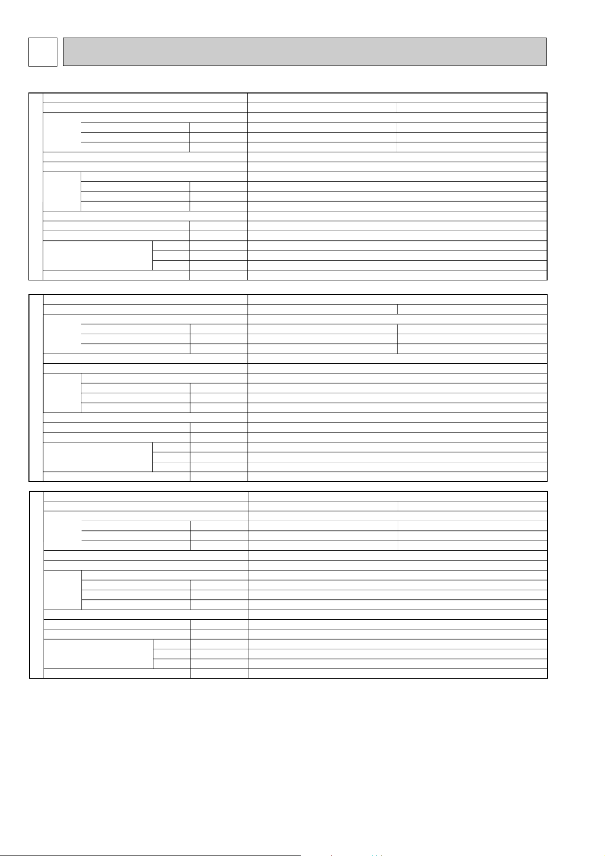
4
kW
A
A
kW
K/min(CFM)
Pa(mmAq)
dB
mm(in.)
mm(in.)
mm(in.)
mm(in.)
kg(lbs)
Service Ref.
Mode
Power supply(phase, cycle, voltage)
Input
Running current
Starting current
External finish
Heat exchanger
Fan Fan(drive) o No.
Fan motor output
Airflow(Low-Medium2-Medium1-High)
External static pressure
Operation control & Thermostat
Noise level(Low-Medium2-Medium1-High)
Unit drain pipe I.D.
Dimensions
Weight
W
D
H
INDOOR UNIT
PMH-P35BA
Cooling
0.06
0.29
0.32
Heating
0.06
0.29
0.32
Single phase, 50Hz, 230V
Unit : Galvanized sheets with gray heat insulation, Grille munsell 0.98Y 8.99/0.63
Plate fin coil
Lineflow fan (direct) o 1
0.028
7.0-8.0-9.0-10.0(247-282-318-353)
0(direct blow)
Remote controller & built-in
34-36-38-40
26(1)
UNIT : 854(33-5/8) PANEL : 1000(39-3/8)
UNIT : 395(15-9/16) PANEL : 470(18-1/2)
UNIT : 230(9-1/16) PANEL : 30(1-3/16)
UNIT : 14(31) PANEL : 3(6.6)
Cooling
0.04
0.19
0.21
Heating
0.04
0.19
0.21
Single phase, 50Hz, 230V
Unit : Galvanized sheets with gray heat insulation, Grille munsell 0.98Y 8.99/0.63
Plate fin coil
Lineflow fan (direct) o 1
0.028
6.3-6.8-7.6-8.4(222-240-268-297)
0(direct blow)
Remote controller & built-in
29-31-33-35
26(1)
PMH-P25BA
kW
A
A
kW
K/min(CFM)
Pa(mmAq)
dB
mm(in.)
mm(in.)
mm(in.)
mm(in.)
kg(lbs)
Service Ref.
Mode
Power supply(phase, cycle, voltage)
Input
Running current
Starting current
External finish
Heat exchanger
Fan Fan(drive) o No.
Fan motor output
Airflow(Low-Medium2-Medium1-High)
External static pressure
Operation control & Thermostat
Noise level(Low-Medium2-Medium1-High)
Unit drain pipe I.D.
Dimensions
Weight
W
D
H
INDOOR UNIT
UNIT : 854(33-5/8) PANEL : 1000(39-3/8)
UNIT : 395(15-9/16) PANEL : 470(18-1/2)
UNIT : 230(9-1/16) PANEL : 30(1-3/16)
UNIT : 14(31) PANEL : 3(6.6)
Cooling
0.06
0.29
0.32
Heating
0.06
0.29
0.32
Single phase, 50Hz, 230V
Unit : Galvanized sheets with gray heat insulation, Grille munsell 0.98Y 8.99/0.63
Plate fin coil
Lineflow fan (direct) o 1
0.028
8.0-9.0-10.0-11.0(282-318-353-388)
0(direct blow)
Remote controller & built-in
36-38-40-42
26(1)
PMH-P50BA
kW
A
A
kW
K/min(CFM)
Pa(mmAq)
dB
mm(in.)
mm(in.)
mm(in.)
mm(in.)
kg(lbs)
Service Ref.
Mode
Power supply(phase, cycle, voltage)
Input
Running current
Starting current
External finish
Heat exchanger
Fan Fan(drive) o No.
Fan motor output
Airflow(Low-Medium2-Medium1-High)
External static pressure
Operation control & Thermostat
Noise level(Low-Medium2-Medium1-High)
Unit drain pipe I.D.
Dimensions
Weight
W
D
H
INDOOR UNIT
UNIT : 854(33-5/8) PANEL : 1000(39-3/8)
UNIT : 395(15-9/16) PANEL : 470(18-1/2)
UNIT : 230(9-1/16) PANEL : 30(1-3/16)
UNIT : 14(31) PANEL : 3(6.6)
SPECIFICATIONS
6
Page 7
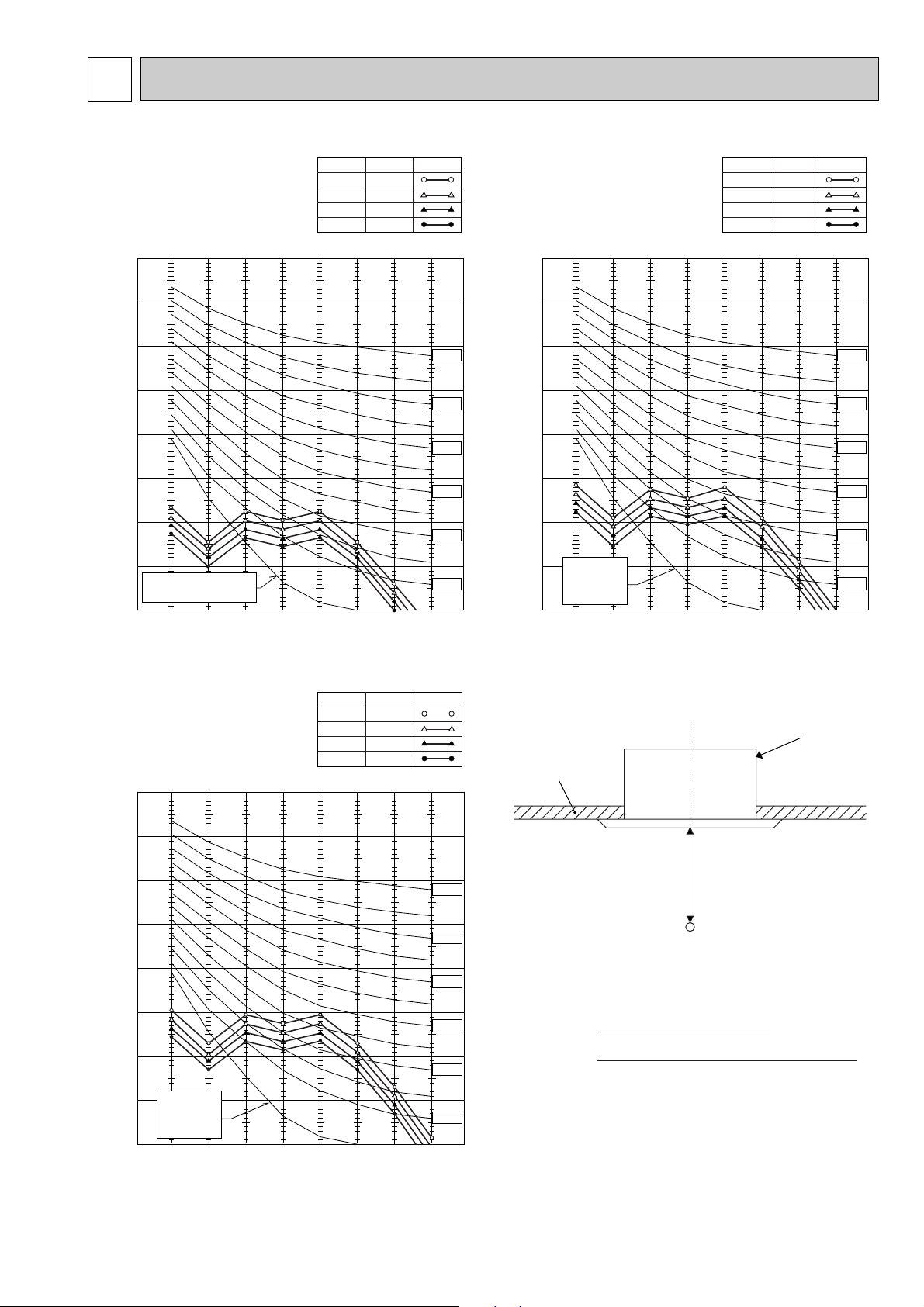
NOISE CRITERION CURVES5
90
80
70
60
50
40
30
20
10
63 125 250 500 1000 2000 4000 8000
APPROXIMATE
THRESHOLD OF
HEARING FOR
CONTINUOUS
NOISE
NC-60
NC-50
NC-40
NC-30
NC-20
NC-70
OCTAVE BAND SOUND PRESSURE LEVEL, dB re 0.002 µ BAR
BAND CENTER FREQUENCIES, Hz
PMH-P35BA
High
NOTCH
Medium1
Medium2
Low
40
SPL(dB)
38
36
34
LINE
90
80
70
60
50
40
30
20
10
63 125 250 500 1000 2000 4000 8000
APPROXIMATE THRESHOLD OF
HEARING FOR CONTINUOUS
NOISE
NC-60
NC-50
NC-40
NC-30
NC-20
NC-70
OCTAVE BAND SOUND PRESSURE LEVEL, dB re 0.002 µ BAR
BAND CENTER FREQUENCIES, Hz
PMH-P25BA
High
NOTCH
Medium1
Medium2
Low
35
SPL(dB)
33
31
29
LINE
Ambient temperature 27:
Test conditions are based on JIS Z8731
UNIT
1.5m
MICROPHONE
CEILING
90
80
70
60
50
40
30
20
10
63 125 250 500 1000 2000 4000 8000
APPROXIMATE
THRESHOLD OF
HEARING FOR
CONTINUOUS
NOISE
NC-60
NC-50
NC-40
NC-30
NC-20
NC-70
OCTAVE BAND SOUND PRESSURE LEVEL, dB re 0.002 µ BAR
BAND CENTER FREQUENCIES, Hz
PMH-P50BA
High
NOTCH
Medium1
Medium2
Low
42
SPL(dB)
40
38
36
LINE
7
Page 8
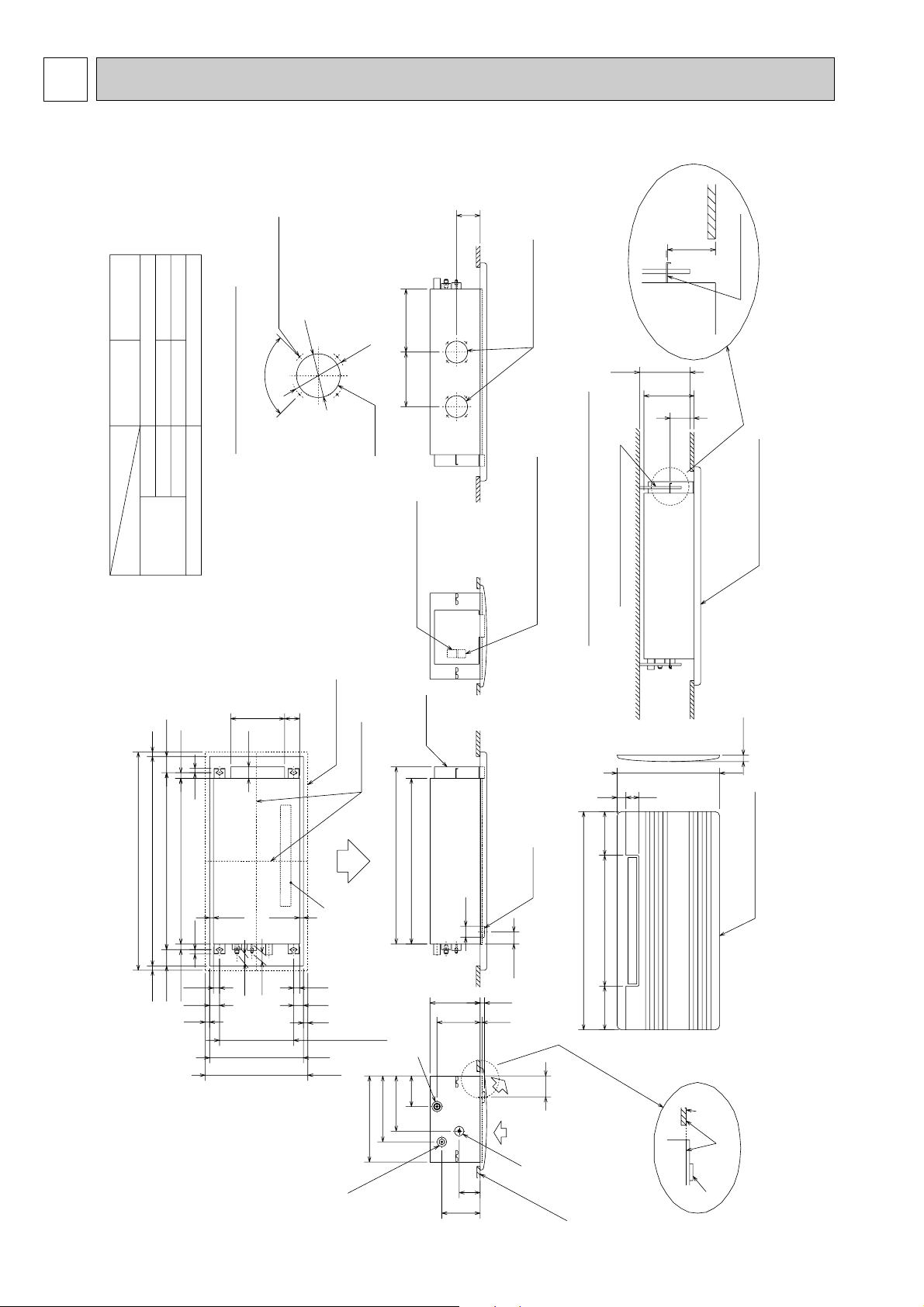
6
OUTLINES AND DIMENSIONS
PMH-P25BA
PMH-P35BA
PMH-P50BA
PMH-P50BA
PMH-P35BA
PMH-P25BA
O.D.{35
O.D.{12.7(1/2") O.D.{15.88(5/8")
O.D.{6.35(1/4") O.D.{9.52(3/8")
Gas pipe
Liquid pipe
pipe cover
Refrigerant
piping
4-{2.8 Burring hole
100
{
90-
PVC pipe:VP-20[O.D.{25(1")]
Details of fresh air intake hole
Drainage piping
122
{
250 288.5
Knock out
Unit : mm
108
110
mounting plate
Flesh air intake hole
235 or more
230
110
Panel(grille):PMP-40BM
74.5
26
20
75926
960 ceiling opening20 20
1000 outer side of grille
811 suspension bolt pitch74.5
20
2828
45
20
Top
247
69
53
17.517.5
43
46
outer line of grille
center of unit
Air outlet(lower)
45
20
340 suspension bolt pitch
430 ceiling opening
470 outer side of grille
302
395
Terminal block for
indoor/outdoor connection
elect box
812
759
{50
230
198
Drainage pipe
PVC pipe:VP-20[O.D.{25]
141
254
Right side
Terminal block for remote controller
suspension bolt(M10 or W3/8)
Installation space required around indoor unit
200600200
drain pan
(56)
Front
(20)
(10)
1000 outer side of grille
(96)
30
470 outer side of grille
60 40
Panel(grille):PMP-40BM
Lower view
ceiling
panel
Refrigerant pipe(gas)
same line
drain pan
96
176
Refrigerant
pipe(liquid)
Left side
ceiling panel
8
Page 9
6 5 4 3 251
MF
FAN
(WHT)
LED1 CN90 CN32
I.B
LED2
LED3
CN41
2 1
REMOTE
CONTROLLER
CN22
(BLU)
BLU
BLU
TB5
TB4
S1
S2
S3
TB6
R.B
TRANSMISSION WIRES DC12V
2
1
12
2
1
TH1
3
2
1
DS
D.SENSOR
CN31
(WHT)
INTAKE
CN20
(RED)
BLK
BLK
BLK
BLK
2
1
TH2
LIQUID
CN21
(WHT)
BLK
BLK
2
1
TH5
PIPE
CN29
(BLK)
BLK
BLK
VANE
CN6V
(WHT)
6
5
4
3
2
1
1
2
3
4
5
MV
BRN
RED
ORN
YLW
GRN
CN2L
See fig :w1
SW1SWE
ON
OFF
SW2
J24
J23
J22
J21
J15
J14
J13
J12
J11
3
1
1
3
5
DP
X1
X1
D.U.M
CNP
(YLW)
POWER
CN03
(RED)
FUSE
ZNR
T
BRN
ORN
YLW
BLU
BLU
TO OUTDOOR UNIT
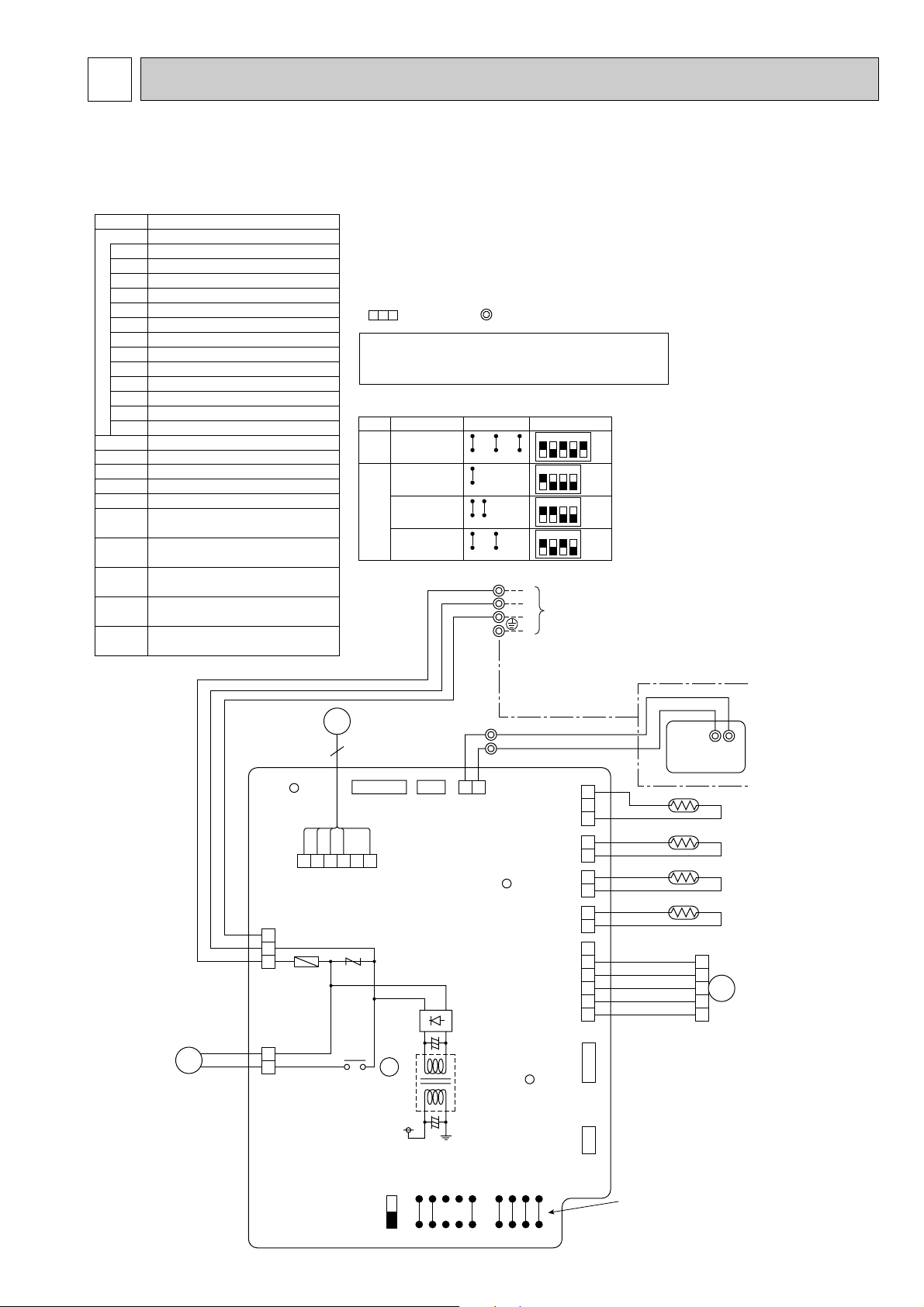
MODELS
SW1
<w1>
PMH-P25/35/50BA
Manufacture
J11 J12 J13 J14 J15
Service board
SW2
PMH-P25BA
J21 J22 J23 J24
ON
OFF
1234
12345
ON
OFF
PMH-P35BA
J21 J22 J23 J24
ON
OFF
1234
PMH-P50BA
J21 J22 J23 J24
ON
OFF
1234
NOTES:
1.Since the outdoor side electric wiring may change be sure
to check the outdoor unit electric wiring for servicing.
2.Indoor and outdoor connecting wires are made with polarities,
make wiring matching terminal numbers (S1, S2, S3).
3.Symbols used in wiring diagram above are,
: Connector, : Terminal (block).
Please set the voltage using the remote controller.
For the setting method, please refer to the indoor
unit Installation Manual.
SYMBOL
[LEGEND]
I.B INDOOR CONTROLLER BOARD
CN2L CONNECTOR(LOSSNAY)
CN32 CONNECTOR(REMOTE SWITCH)
R.B
WIRED REMOTE CONTROLLER BOARD
DP DRAIN-UP MACHINE
DS DRAIN SENSOR
MF FAN MOTOR
MV
TB4
VANE MOTOR
TERMINAL BLOCK
(INDOOR / OUTDOOR CONNECTING LINE)
TB5,TB6 TERMINAL BLOCK
(REMOTE CONTROL TRANSMISSION LINE)
TH1 ROOM TEMP, THERMISTOR
(0:/15k", 25:/5.4k" DETECT)
TH2 PIPE TEMP, THERMISTOR / LIQUID
(0:/15k", 25:/5.4k" DETECT)
TH5 COND, / EVA, TEMP, THERMISTOR
(0:/15k", 25:/5.4k" DETECT)
CN41 CONNECTOR(HA TERMINAL-A)
FUSE FUSE(6.3A , 250V)
LED1 POWER SUPPLY(I.B)
LED2 POWER SUPPLY(R.B)
LED3 TRANSMISSION(INDOOR-OUTDOOR)
SW1 JUMPER WIRE(MODEL SELECTION)
SW2 JUMPER WIRE(CAPACITY CORD)
SWE SWITCH(EMERGENCY OPERATION)
T TRANSFORMER
X1 RELAY(DRAIN PUMP)
ZNR VARISTOR
NAME
7
WIRING DIAGRAM
PMH-P25BA
PMH-P35BA
PMH-P50BA
9
Page 10

Pipe temperature
thermistor/liquid
(TH2)
Distributor
with strainer
#50
Condenser/evaporator
temperature thermistor
(TH5)
Room temperature
thermistor (TH1)
Refrigerant flow in cooling
Refrigerant flow in heating
Strainer
#50
Strainer
#50
Heat exchanger
Refrigerant GAS pipe connection
(Flare)
Refrigerant LIQUID pipe connection
(Flare)
8
REFRIGERANT SYSTEM DIAGRAM
PMH-P25BA
PMH-P35BA
PMH-P50BA
Unit : mm
10
Page 11

9 TROUBLESHOOTING
Unit conditions at service
Error code
Actions to be taken for service (summary)
The inferior phenomenon is
reoccurring.
Displayed
Not displayed
Judge what is wrong and take a corrective action
according to “SELF-DIAGNOSIS ACTION TABLE” (9-2).
Identify the cause of the inferior phenomenon and take
a corrective action according to “TROUBLESHOOTING
BY INFERIOR PHENOMENA ” (9-3).
The inferior phenomenon is
not reoccurring.
Logged
Not logged
1Consider the temporary defects such as the work of
protection devices in the refrigerant circuit including
compressor, poor connection of wiring, noise and etc.
Re-check the symptom, and check the installation
environment, refrigerant amount, weather when the
inferior phenomenon occurred, and wiring related.
2Reset error code logs and restart the unit after finishing
service.
3There is no abnormality in electrical components,
controller boards, and remote controller.
1Recheck the abnormal symptom.
2Identify the cause of the inferior phenomenon and take
a corrective action according to “TROUBLESHOOTING
BY INFERIOR PHENOMENA ” (9-3).
3Continue to operate unit for the time being if the cause
is not ascertained.
4There is no abnormality in electrical components,
controller boards, remote controller etc.
9-1. TROUBLESHOOTING
<Error code display by self-diagnosis and actions to be taken for service (summary)>
Present and past error codes are logged and displayed on the wired remote controller or controller board of outdoor unit.
Actions to be taken for service and the inferior phenomenon reoccurrence at field are summarized in the table below. Check
the contents below before investigating details.
11
Page 12

9-2. SELF-DIAGNOSIS ACTION TABLE
Error Code
P1
P2
Meaning of error code and detection method
Abnormality of room temperature
thermistor (TH1)
1 The unit is in three-minute resume
prevention mode if short/open of
thermistor is detected. Abnormal if the
unit does not reset normally after three
minutes. (The unit returns to normal
operation, if it has normally reset.)
2 Constantly detected during cooling,
drying, and heating operation.
Short: 90: or more
Open: -40: or less
Abnormality of pipe temperature
thermistor/Liquid (TH2)
1 The unit is in three-minute resume
prevention mode if short/open of
thermistor is detected. Abnormal if the
unit does not reset normally after three
minutes. (The unit returns to normal
operation, if it has normally reset.)
2 Constantly detected during cooling,
drying, and heating (except defrosting)
operation.
Short: 90: or more
Open: -40: or less
Note: Refer to the manual of outdoor unit for the details of display
such as F, U, and other E.
Cause
1 Defective thermistor
characteristics.
2 Contact failure of connector
(CN20) on the indoor controller
board. (Insert failure)
3 Breaking of wire or contact
failure of thermistor wiring.
4 Defective indoor controller
board.
1 Defective thermistor
characteristics.
2 Contact failure of connector
(CN21) on the indoor controller
board. (Insert failure)
3 Breaking of wire or contact
failure of thermistor wiring.
4 Defective refrigerant circuit is
causing thermistor temperature
of 90: or more or -40: or
less.
5 Defective indoor controller board.
Countermeasure
1–3 Check resistance value of thermistor.
0: ······15.0k"
10: ····9.6k"
20: ····6.3k"
30: ····4.3k"
40: ····3.0k"
If you put force on (draw or bend) the lead wire
with measuring resistance value of thermistor
breaking of wire or contact failure can be
detected.
2 Check contact failure of connector (CN20) on
the indoor controller board. Refer to 9-6.
Turn the power on again and check restart
after inserting connector again.
4 Check room temperature display on remote
controller.
Replace indoor controller board if there is
abnormal difference with actual room
temperature.
Turn the power off, and on again to operate
after check.
1–3 Check resistance value of thermistor.
For characteristics, refer to (P1) above.
2 Check contact failure of connector (CN21) on
the indoor controller board. Refer to 9-6. Turn
the power on and check restart after inserting
connector again.
4 Check pipe <liquid> temperature with remote
controller in test run mode. If pipe <liquid>
temperature is exclusively low (in cooling
mode) or high (in heating mode), refrigerant
circuit may have defective.
5 Check pipe <liquid> temperature with remote
controller in test run mode. If there is exclusive
difference with actual pipe <liquid> temperature,
replace indoor controller board.
P4
P5
Abnormality of drain sensor (DS)
1 Suspensive abnormality, if short/open of
thermistor is detected for 30 seconds
continuously.
Turn off compressor and indoor fan.
2 Short/open is detected for 30 seconds
continuously during suspensive
abnormality.
(The unit returns to normal operation,
if it has normally reset.)
3 Detect the following condition.
• During cooling and drying operation.
• In case that pipe <liquid> temperature
- room temperature <-10deg
(Except defrosting)
• When pipe <liquid> temperature or
room temperature is short/open
temperature.
• During drain pomp operation.
Malfunction of drain pump (DP)
1 Suspensive abnormality, if thermistor
of drain sensor is let heat itself and
temperature rises slightly. Turn off
compressor and indoor fan.
2 Drain pomp is abnormal if the condition
above is detected during suspensive
abnormality.
3 Constantly detected during drain pomp
operation.
1 Defective thermistor
characteristics
2 Contact failure of connector
(CN31) on the indoor controller
board. (Insert failure).
3 Breaking of wire or contact
failure of drain sensor wiring.
4 Defective indoor controller board.
1 Malfunction of drain pump
2 Defective drain
Clogged drain pump
Clogged drain pipe
3 Attached drop of water at the
drain sensor
• Drops of drain trickles from
lead wire.
• Clogged filter is causing
wave of drain.
4 Defective indoor controller board.
Turn the power off, and on again to operate
after check.
1–3 Check resistance value of thermistor.
0: ······6.0k"
10: ····3.9k"
20: ····2.6k"
30: ····1.8k"
40: ····1.3k"
2 Check contact failure of connector (CN31) on
the indoor controller board. Refer to 9-6. Turn
the power on again and check restart after
inserting connector again.
4 Replace indoor controller board if drain
pump operates with the line of drain sensor
connector CN31-1 and 2 is short-circuited,
and abnormality reappears.
Turn the power off, and on again to operate
after check.
1 Check if drain-up machine works.
2 Check drain function.
3 Check the setting of lead wire of drain sensor
and check clogs of the filter.
4 Replace indoor controller board if drain
pump operates with the line of drain sensor
connector CN31-1 and 2 is short-circuited
and abnormality reappears.
Refer to 9-6.
Turn the power off, and on again to operate
after check.
12
Page 13

Error Code
P6
Meaning of error code and detection method
Freezing/overheating protection is
working
1 Freezing protection (Cooling mode)
The unit is in six-minute resume prevention
mode if pipe <liquid or condenser/evaporator> temperature stays under
-15: for three minutes, three minutes
after the compressor started. Abnormal
if it stays under -15: for three minutes
again within 16 minutes after six-minute
resume prevention mode.
<Frost prevention mode>
If pipe <liquid or condenser-evaporator>
temperature is 2: or below when 16
minutes has passed after compressor
starts operating, unit will start operating
in frost prevention mode which stops
compressor operation. After that, when
pipe <liquid or condenser/evaporator>
temperature stays 10: or more for 3
minutes, frost prevention mode will be
released and compressor will restart its
operation.
2 Overheating protection (Heating mode)
The units is in six-minute resume
prevention mode if pipe <condenser /
evaporator> temperature is detected as
over 70: after the compressor started.
Abnormal if the temperature of over
70: is detected again within 10 minutes
after six-minute resume prevention
mode.
(Cooling or drying mode)
1 Clogged filter (reduced airflow)
2 Short cycle of air path
3 Low-load (low temperature)
4 Defective indoor fan motor
• Fan motor is defective.
• Indoor controller board is
5 Defective outdoor fan control
6 Overcharge of refrigerant
7 Defective refrigerant circuit
(Heating mode)
1 Clogged filter (reduced airflow)
2 Short cycle of air path
3 Over-load (high temperature)
4 Defective indoor fan motor
• Fan motor is defective.
• Indoor controller board is
5 Defective outdoor fan control
6 Overcharge of refrigerant
7 Defective refrigerant circuit
8 Bypass circuit of outdoor unit
Cause
operation beyond the tolerance
range
defective.
(clogs)
operation beyond the tolerance
range
defective.
(clogs)
is defective.
Countermeasure
(Cooling or drying mode)
1 Check clogs of the filter.
2 Remove shields.
4 Refer to 9-5.
5 Check outdoor fan motor.
67 Check operating condition of refrigerant
circuit.
(Heating mode)
1 Check clogs of the filter.
2 Remove shields.
4 Refer to 9-5.
5 Check outdoor fan motor.
6~8 Check operating condition of refrigerant
circuit.
P8
Abnormality of pipe temperature
<Cooling mode>
Detected as abnormal when the pipe temperature is not in the cooling range 3 minutes later of compressor start and 6 minutes later of the liquid or condenser/evaporator pipe is out of cooling range.
Note 1) It takes at least 9 min. to detect.
Note 2) Abnormality P8 is not detected in
drying mode.
Cooling range : -3 deg ] (TH-TH1)
TH: Lower temperature between: liquid
pipe temperature (TH2) and condenser/evaporator temperature (TH5)
TH1: Intake temperature
<Heating mode>
When 10 seconds have passed after the
compressor starts operation and the hot
adjustment mode has finished, the unit is
detected as abnormal when
condenser/evaporator pipe temperature is
not in heating range within 20 minutes.
Note 3) It takes at least 27 minutes to
detect abnormality.
Note 4) It excludes the period of defrosting
(Detection restarts when defrosting
mode is over)
Heating range : 3 deg [ (TH5-TH1)
1 Slight temperature difference
between indoor room
temperature and pipe <liquid
or condenser / evaporator>
temperature thermistor
• Shortage of refrigerant
• Disconnected holder of pipe
<liquid or condenser /
evaporator> thermistor
• Defective refrigerant circuit
2 Converse connection of
extension pipe (on plural units
connection)
3 Converse wiring of indoor/
outdoor unit connecting wire
(on plural units connection)
4 Defective detection of indoor
room temperature and pipe
<condenser / evaporator>
temperature thermistor
5 Stop valve is not opened
completely.
1~4 Check pipe <liquid or condenser /
evaporator> temperature with room
temperature display on remote
controller and outdoor controller circuit
board.
Pipe <liquid or condenser / evaporator>
temperature display is indicated by
setting SW2 of outdoor controller circuit
board as follows.
Conduct temperature check with outdoor
controller circuit board after connecting
(
‘A-Control Service Tool(PAC-SK52ST)’.
23Check converse connection of extension
pipe or converse wiring of indoor/outdoor
unit connecting wire.
)
13
Page 14

Error Code
P9
E0
or
E4
E3
or
E5
Meaning of error code and detection method
Abnormality of pipe temperature thermistor / Condenser-Evaporator (TH5)
1 The unit is in three-minute resume pro-
tection mode if short/open of thermistor
is detected. Abnormal if the unit does
not get back to normal within three minutes. (The unit returns to normal operation, if it has normally reset.)
2 Constantly detected during cooling, dry-
ing, and heating operation (except
defrosting)
Short: 90: or more
Open: -40: or less
Remote controller transmission
error(E0)/signal receiving error(E4)
1 Abnormal if main or sub remote con-
troller can not receive normally any
transmission from indoor unit of refrigerant address “0” for three minutes.
(Error code : E0)
2 Abnormal if sub remote controller could
not receive for any signal for two minutes. (Error code: E0)
1 Abnormal if indoor controller board can
not receive normally any data from
remote controller board or from other
indoor controller board for three minutes.
(Error code: E4)
2 Indoor controller board cannot receive
any signal from remote controller for two
minutes. (Error code: E4)
Remote controller transmission
error(E3)/signal receiving error(E5)
1 Abnormal if remote controller could not
find blank of transmission path for six
seconds and could not transmit.
(Error code: E3)
2 Remote controller receives transmitted
data at the same time, compares the
data, and when detecting it, judges
different data to be abnormal 30
continuous times. (Error code: E3)
1 Abnormal if indoor controller board could
not find blank of transmission path.
(Error code: E5)
2 Indoor controller board receives trans-
mitted data at the same time, compares
the data,and when detecting it, judges
different data to be abnormal 30
continuous times. (Error code: E5)
1 Defective thermistor
2 Contact failure of connector
3 Breaking of wire or contact
4 Temperature of thermistor is
5 Defective indoor controller
1 Contact failure at transmission
2 All remote controllers are set
3 Mis-wiring of remote controller.
4 Defective transmitting receiving
5 Defective transmitting receiving
6 Noise has entered into the
1 Two remote controller are set
2 Remote controller is connected
3 Repetition of refrigerant
4 Defective transmitting receiving
5 Defective transmitting receiving
6 Noise has entered into trans-
Cause
characteristics
(CN29) on the indoor controller
board. (Insert failure)
failure of thermistor wiring.
90: or more or -40: or less
caused by defective refrigerant
circuit.
board.
wire of remote controller
as “sub” remote controller. In
this case, E0 is displayed on
remote controller, and E4 is
displayed at LED (LED1, LED2)
on the outdoor controller circuit
board.
circuit of remote controller
circuit of indoor controller board
of refrigerant address “0”.
transmission wire of remote
controller.
as “main.”
(In case of 2 remote con-
trollers)
with two indoor units or more.
address.
circuit of remote controller.
circuit of indoor controller
board.
mission wire of remote con-
troller.
Countermeasure
1–3 Check resistance value of thermistor.
For characteristics, refer to (P1) above.
2 Check contact failure of connector (CN29)
on the indoor controller board.
Refer to 9-6.
Turn the power on and check restart after
inserting connector again.
4 Operate in test run mode and check pipe
<condenser / evaporator> temperature with
outdoor controller circuit board. If pipe
<condenser / evaporator> temperature is
exclusively low (in cooling mode) or high (in
heating mode), refrigerant circuit may have
defective.
5 Operate in test run mode and check pipe
<condenser / evaporator> temperature with
outdoor control circuit board. If there is
exclusive difference with actual pipe
<condenser / evaporator> temperature
replace indoor controller board.
There is no abnormality if none of above
comes within the unit.
Turn the power off and on again to operate.
In case of checking pipe temperature
with outdoor controller circuit board,
be sure to connect A-control service
(
tool (PAC-SK52ST).
1 Check disconnection or looseness of indoor
unit or transmission wire of remote controller.
2 Set one of the remote controllers “main”.
If there is no problem with the action above.
3 Check wiring of remote controller.
• Total wiring length: max.500m
(Do not use cablex 3 or more)
• The number of connecting indoor units:
max.16units
• The number of connecting remote controller: max.2units
When it is not the above-mentioned problem of
1~3
4 Diagnose remote controllers.
a) When “RC OK” is displayed,
Remote controllers have no problem.
Put the power off, and on again to check.
If abnormality generates again, replace
indoor controller board.
b) When “RC NG” is displayed,
Replace remote controller.
c) When “RC E3” is displayed,
d) When “ERC 00-06” is displayed,
[ c),d)→Noise may be causing abnormality. ]
∗ If the unit is not normal after replacing
indoor controller board in group control,
indoor controller board of address “0”
may be abnormal.
1 Set a remote controller to main, and the
other to sub.
2 Remote controller is connected with only one
indoor unit.
3 The address changes to a separate setting.
4~6 Diagnose remote controller.
a) When “RC OK”is displayed, remote con-
trollers have no problem.
Put the power off,and on again to check.
When becoming abnormal again, replace
indoor controller board.
b)When “RC NG”is displayed, replace
remote controller.
c)When “RC E3”or “ERC 00-66”is displayed,
noise may be causing abnormality.
)
14
Page 15

Error Code
E6
E7
E1
or
E2
Meaning of error code and detection method
Indoor/outdoor unit communication
error (Signal receiving error)
1 Abnormal if indoor controller board
cannot receive any signal normally for
six minutes after putting the power on.
2 Abnormal if indoor controller board
cannot receive any signal normally for
three minutes.
3 Consider the unit abnormal under the
following condition: When two or more
indoor units are connected to one
outdoor unit, indoor controller board
cannot receive a signal for three minutes
from outdoor controller circuit board, a
signal which allows outdoor controller
circuit board to transmit signals.
Indoor/outdoor unit communication
error (Transmitting error)
Abnormal if “1” receiving is detected 30
times continuously though indoor controller
board has transmitted “0”.
Abnormality of remote controller control board
1 Abnormal if data cannot be normally
read from the nonvolatile memory of the
remote controller control board.
(Error code: E1)
2 Abnormal if the clock function of remote
controller cannot be normally operated.
(Error code: E2)
1 Contact failure, short circuit or,
2 Defective transmitting receiving
3 Defective transmitting receiving
4 Noise has entered into indoor/
1 Defective transmitting receiving
2 Noise has entered into power
3 Noise has entered into outdoor
1 Defective remote controller. 1 Replace remote controller.
Cause
mis-wiring (converse wiring) of
indoor/outdoor unit connecting
wire
circuit of indoor controller board
circuit of indoor controller board
outdoor unit connecting wire.
circuit of indoor controller board
supply.
control wire.
Countermeasure
∗ Check LED display on the outdoor control cir-
cuit board. (Connect A-control service tool,
PAC-SK52ST.)
Refer to EA-EC item if LED displays EA-EC.
1 Check disconnection or looseness of indoor/
outdoor unit connecting wire of indoor unit or
outdoor unit.
Check all the units in case of twin triple
indoor unit system.
2-4 Turn the power off, and on again to
check. If abnormality generates again,
replace indoor controller board or outdoor
controller circuit board.
∗ Other indoor controller board may have
defective in case of twin triple indoor unit
system.
1-3 Turn the power off, and on again to
check. If abnormality generates again,
replace indoor controller board.
15
Page 16

9-3. TROUBLESHOOTING BY INFERIOR PHENOMENA
Note: Refer to the manual of outdoor unit for the detail of remote
controller.
Phenomena
(1)LED2 on indoor controller board
is off.
• When LED1 on indoor controller board is also off.
1 Power supply of 220~240V is not supplied to outdoor
unit.
2 Defective outdoor controller circuit board.
3 Power supply of 220~240V is not supplied to indoor
unit.
4 Defective indoor controller board.
• When LED1 on indoor controller board is lit.
1 Mis-setting of refrigerant address for outdoor unit
(There is no unit corresponding to refrigerant
address “0”.)
Factor
Countermeasure
1 Check the voltage of outdoor power
supply terminal block (L, N)
• When AC 220~240V is not detected.
Check the power wiring to outdoor unit
and the breaker.
• When AC 220~240V is detected.
—Check 2 (below).
2 Check the voltage between outdoor
terminal block S1 and S2.
• When AC 220~240V is not detected.
Check the fuse on outdoor controller
circuit board (10A).
Check the wiring connection.
• When AC 220~240V is detected.
—Check 3 (below).
3 Check the voltage between indoor terminal
block S1 and S2.
• When AC 220~240V is not detected.
Check indoor/outdoor unit connecting
wire for mis-wiring.
• When AC 220~240V is detected.
—Check 4 (below).
4 If no problems are found(1~3), indoor
controller board is defective.
1 Reconfirm the setting of refrigerant
address for outdoor unit
Set the refrigerant address to “0”.
(For grouping control system under
which 2 or more outdoor units are
connected, set one of the units to “0”.)
Set refrigerant address using SW1
on outdoor controller circuit board.
(2)LED2 on indoor controller board
is blinking.
(3)Upward/downward vane perfor-
mance failure
• When LED1 on indoor controller board is also blinking.
Connection failure of indoor/outdoor unit connecting
wire
• When LED1 is lit.
Mis-wiring of remote controller wires
Under twin triple indoor unit system, 2 or more indoor
units are wired together.
1 Refrigerant address for outdoor unit is wrong or not
set.
Under grouping control system, there are some units
whose refrigerant address is 0.
2 Short-cut of remote controller wires
3 Defective remote controller
1 The vane is not downward during defrosting and
heat preparation and when the thermostat is OFF in
HEAT mode. (Working of COOL protection function)
2 Vane motor does not rotate.
• Defective vane motor
• Breaking of wire or connection failure of connector
3 Upward/downward vane does not work.
• The vane is set to fixed position.
Check indoor/outdoor unit connecting wire
for connection failure. Check the connection
of remote controller wires in case of twin
triple indoor unit system. When 2 or more
indoor units are wired in one refrigerant
system, connect remote controller wires to
one of those units.
1 Check the setting of refrigerant address
in case of grouping control system.
If there are some units whose refrigerant
addresses are 0 in one group, set one of
the units to 0 using SW1 on outdoor
controller circuit board.
23 Remove remote controller wires and
check LED2 on indoor controller board.
• When LED2 is blinking, check the
short-cut of remote controller wires.
• When LED2 is lit, connect remote
controller wires again and:
if LED2 is blinking, remote controller
is defective; if LED2 is lit, connection
failure of remote controller terminal
block etc. has returned to normal.
1 Normal operation (The vane is set to hor-
izontal regardless of remote control.)
2 Check 2 (left).
• Check the vane motor. (Refer to “How
to check the parts”.)
• Check for breaking of wire or connection failure of connector.
3 Normal operation (Each connector on
vane motor side is disconnected.)
16
Page 17

9-4. WHEN WIRED REMOTE CONTROLLER OR INDOOR UNIT MICRO COMPUTE TROUBLES
Parts name Check points
Disconnect the connector then measure the resistance using a tester.
(Surrounding temperature 10:~30:)
Measure the resistance between the terminals using a tester.
(Surrounding temperature 20:~30:)
Measure the resistance between the terminals using a tester.
(Surrounding temperature 20:)
Measure the resistance between the terminals using a tester.
(Surrounding temperature 20:~30:)
Vane motor
Drain-up
mechanism
Drain sensor
(Refer to <Thermistor Characteristic graph> in detail.)
(Refer to <Thermistor Characteristic graph> in detail.)
Room temperature
thermistor (TH1)
Pipe temperature
thermistor (TH2)
Condenser/evaporator
temperature thermistor
(TH5)
1
3
Blue
Blue
1
2
3
Normal
4.3k"~9.6k"
Abnormal
Open or short
Abnormal
Open or short
Normal
0.6k"~6.0k"
NormalConnector Abnormal
380" i7% Open or short
Normal Abnormal
400"~480" Open or short
MV
Orange
Red
Brown
Brown — Yellow
Brown — Red
Brown — Orange
Brown — Green
Green
Yellow
31
5
4
2
1. If there is not any other wrong when trouble occurs, emergency operation starts as the indoor controller board switch (SWE)
is set to ON.
During the emergency operation the indoor unit is as follows;
(1) Indoor fan high speed operation (2) Drain-up machine operation
2. When emergency operating for COOL or HEAT, setting of the switch (SWE) in the indoor controller board and outdoor unit
emergency operation are necessary.
3. Check items and notices as the emergency operation
(1) Emergency operation cannot be used as follows;
• When the outdoor unit is something wrong.
• When the indoor fan is something wrong.
• When drain over flow protected operation is detected during self-diagnosis. (Error code : P5)
(2) Emergency operation will be serial operation by the power supply ON/OFF.
ON/OFF or temperature, etc. adjustment is not operated by the remote controller.
(3) Do not operate for a long time as cold air is blown when the outdoor unit starts defrosting operation during heat emer-
gency operation.
(4) Cool emergency operation must be within 10 hours. Otherwise, heat exchanger of indoor unit may get frosted.
(5) After completing the emergency operation, return the switch setting, etc. in former state.
(6) Since vane does not work at emergency operation, position the vane slowly by hand.
9-5. HOW TO CHECK THE PARTS
PMH-P25BA
PMH-P35BA
PMH-P50BA
17
Page 18

Notes
· High voltage is applied to the connecter (FAN) for the fan motor. Give attention to the service.
· Do not pull out the connector (Fan) for the motor with the power supply on.
(It causes trouble of the control
p.c.board)
Self check
Conditions : The indoor fan cannot turn around.
No
Wiring contact check
Contact of fan motor connector (FAN)
Contact of power supply cable.
Fan motor check
Measure the resistance between the fan motor connecter 1(+) and 3( ).
(With the connecter is pulled out from the
p.c.board)
Power supply check
Check the voltage in the indoor control
p.c.board
Approx. 310~340V between the connecter (FAN) 1(+) and 3( ).
Approx. 1~3V between the connecter (FAN) 5(+) and 3( ).
The voltage between the 5 and 3 is a value during the fan motor operation.
In the case that the fan motor off, the voltage is 0V.
Fan motor position sensor signal check
Turn around the fan motor more than one revolution slowly, and check
the voltage between the connecter (FAN) 6(+) and 3( ).
Check method of indoor fan motor (fan motor / control p.c.board)
Wiring recovery
Trouble of the fan motor Replacement of the motor
Is the resistance 1M" or more?
Trouble of the indoor
p.c.board
Replacement of the indoor control
p.c.board
Trouble of the fan motor
Replacement of the motor
Dose the voltage repeat DC0V and DC15V?
Replacement of the indoor control
p.c.board
Is the voltage normal?
Was contact caused good?
Yes
1
2
No
Yes
No
Yes
No
Yes
18
Page 19

<Thermistor Characteristic graph>
-200 20406080
< Thermistor for drain sensor >
Temperature (:)
0
1
2
3
4
5
6
7
8
9
10
Resistance (K")
Thermistor for
lower temperature
Room temperature thermistor(TH1)
Pipe temperature thermistor(TH2)
Condenser/evaporator temperature
thermistor(TH5)
Thermistor R0=15kΩ ±3%
Fixed number of B=3480 ± 2%
Rt=15exp { 3480( ) }
1
273+t
1
273
0: 15kΩ
10: 9.6kΩ
20: 6.3kΩ
25: 5.4kΩ
30: 4.3kΩ
40: 3.0kΩ
Thermistor for
drain sensor
< Thermistor for lower temperature >
50
40
30
20
Resistance (K")
10
0
-20 -10 0 10 20 30 40 50
Temperature (:)
Thermistor R0=6.0kΩ ±5%
Fixed number of B=3390 ±2%
Rt=6exp { 3390( ) }
0: 6.0kΩ
10: 3.9kΩ
20: 2.6kΩ
25: 2.2kΩ
30: 1.8kΩ
40: 1.3kΩ
1
273+t
1
273
19
Page 20

9-6. TEST POINT DIAGRAM
Indoor controller board
PMH-P25BA
PMH-P35BA
PMH-P50BA
FAN
Fan motor output (MF)
Between 1 to 5
220~240V AC
CN03
Connect to the outdoor unit
Between 1 to 3
220~240V AC
Between 3 to 5
0~24V DC
}
CN90
Connect to the wireless
remote controller board
CN32
Connector
(Remote switch)
CN22
Connect to the terminal block (TB5)
(Remote controller connecting wire)
(10~16V DC)
}
+
–
CN31
Drain sensor (DS)
CN20
Room temperature
thermistor (TH1)
CN21
Pipe temperature
thermistor/Liquid (TH2)
CN29
Condenser/Evaporator
temperature thermistor
(TH5)
CN6V
Vane motor output
(MV)
CN41
Connector
(HA terminal-A)
+
–
CNP
Drain-up machine
output (DP)
Between 1 to 3
220~240V AC
Jumper wire J41, J42
Pair number setting with
wireless remote controller
SWE
Emergency
operation
Jumper wire J11~J15
Model setting
CN2L
Connector
(LOSSNAY)
CN25
–
Humidifier output
}
+
(12~16V DC)
Jumper wire J21~J24
Capacity setting
20
Page 21

9-7. FUNCTIONS OF JUMPER WIRE
J11~J15
(SW1)
Open/short of jumper wire
Functions
Jumper wire
Model
settings
Capacity
settings
Pair number
setting with
wireless
remote
controller
Remarks
J21~J24
(SW2)
J41
J42
0
1
2
3 ~ 9
Wireless remote
controller setting
Control PCB setting
J41 J42
<Settings at time of factory shipment>
Wireless remote controller: 0
Control PCB: (for both J41 and J42)
Four pair number settings are supported.
The pair number settings of the wireless remote
controller and indoor control PCB (J41/J42) are
given in the table on the left.
(' ' in the table indicates the jumper line is disconnected.)
(Marks in the table below) Jumper wire ( : Short : Open)
DIP switch ( : ON : OFF)
MODELS
SW1
PMH-P25/35/50BA
Manufacture
J11 J12 J13 J14 J15
Service board
12345
ON
OFF
MODELS Manufacture Service board
SW2
PMH-P25BA
J21 J22 J23 J24
ON
OFF
1234
PMH-P35BA
J21 J22 J23 J24
ON
OFF
1234
PMH-P50BA
J21 J22 J23 J24
ON
OFF
1234
Each function is controlled by the jumper wire on control p.c. board. For service parts, J11- J15 and J21-J24, DIP switches
(SW1 and SW2) are equipped with jumper wire.
21
Page 22

10
DISASSEMBLY PROCEDURE
PMH-P25BA
PMH-P35BA
PMH-P50BA
Be careful on removing heavy parts.
OPERATING PROCEDURE PHOTOS&ILLUSTRATIONS
1. Removing the intake grille
Opening the air intake grille
(1) Press the of the air intake grille.(See figure 1)
(2) Put your figure on the both end of nut of the air intake grille
and put it down after the grille clicked.
Removing the air intake grille
(1) Press the of air intake grille, and pull down the both
end of nut with your fingers after the grille clicked.
(See figure 1)
(2) Pull out the handle of air intake grille strong toward you.
(See figure 2)
(3) Draw the string of air intake grille to prevent the grille from
dropping.(see figure 3)
PUSH
PUSH
Photo 1
Air filter
Figure 1
Figure 2
Figure 3
22
Page 23

OPERATING PROCEDURE PHOTOS&ILLUSTRATIONS
2. Removing the electrical parts box
(1) Remove the panel.
(2) Remove the cover.
(3) Remove the electrical parts cover.
(4) Disconnect the connectors of fan motor, vane motor, drain
pump, room temperature thermistor, pipe temperature
thermistor, condenser/evaporator temperature thermistor
and drain sensor on the electrical controller board.
(5) Disconnect the lead wire and earth wire from terminal
block.
(6) Remove the electrical parts box.
3. Removing the stabilizer
Note when the stabilizer is removed
Photo 2
Drain pan
Photo 3
Photo 4
Claw in middle
of stabilizer
Stabilizer
Stabilizer
Heat exchanger
Electrical parts
cover
Electrical parts
cover
• Since the insulation material (white) which prevents
water-drops from putting is mounted to the side of vane
motor, remove the insulation material when the stabilizer
is removed.(See figure 4)
• After completing the service, mount the insulation material
as before as shown in right figure.
• The insulation material consists of soft and hard layers.
Mount the insulation with the hard layer on the stabilizer
side.
(1) Remove the panel.
(2) Remove the room temperature thermistor.
(3) Unhook the claw in the middle of stabilizer and remove
the drain pan. (5 screws) (See photo 2)
(4) Remove the stabilizer side of the heat exchanger. (2 screws)
(5) Remove the cover.
(6) Remove the electrical parts cover.
(7) Disconnect the connector of vane motor.
(8) Remove the insulation material (white) on the right side of
stabilizer.
(9)Remove the stabilizer. (6 screws)
4. Removing the vane motor
(1) Remove the stabilizer. Refer to above-mentioned (3)
Removing the stabilizer.
(2) Remove the vane motor.
Figure 4
Stabilizer
Photo 5
Room temperature thermistor
Hard material
Insulation material
Vane motor
Soft material
Vane motor
23
Page 24

OPERATING PROCEDURE PHOTOS&ILLUSTRATIONS
5. Removing the drain pump
(1) Remove the panel.
(2) Unhook the claw in the middle of stabilizer and remove
the drain pan.
(3) Remove the cover.
(4) Remove the electrical parts cover.
(5) Disconnect the connector of drain pump.
(6) Remove the drain hose.
(7) Remove the drain pump.(2 screws)
6. Removing the fan motor and line flow fan
(1) Remove the panel.
(2) Unhook the claw in the middle of stabilizer and remove
the drain pan.
(3) Remove 2 screws at the stabilizer side of the heat
exchanger
(4) Remove the cover.
(5) Remove the electrical parts cover.
(6) Disconnect the connectors of vane motor, fan motor and
drain pump.
(7) Remove the stabilizer side of the heat exchanger. (2 screws)
(8) Remove the stabilizer.
(9) Remove the drain pump.
(10) Remove 2 screws in the motor support.
(11) Remove the fan motor and line flow fan (The fan motor
and line flow fan can be removed without removing the
heat exchanger.)
Photo 6
Photo 7
Drain sensor
Line flow fan
Drain pump
Fan motor
Fan motor
7. Removing the thermistor<Room temperature thermistor>
(1) Remove the panel.
(2) Bring down the electrical parts box and remove the cover.
(3) Remove the thermistor <Room temperature thermistor>
(4) Disconnect the lead wire from the cord clamp (5 points)
(5) Disconnect the connector (CN20) on the indoor controller
board.
8. Removing the thermistor<Pipe temperature thermistor/liquid>
<Condenser/evaporator temperature thermistor>
(1) Remove the panel.
(2) Bring down the electrical parts box and remove the cover.
(3) Remove the drain pan.
(4) Remove the thermistor <Pipe temperature thermistor/liquid>
/<Condenser/evaporator temperature thermistor>.
(5) Disconnect the lead wire from the cord clamp
(6) Disconnect the connector (CN29)/(CN21) on the indoor
controller board.
24
Page 25

11
1
2
3
4
5
6
7
8
9
10
11
12
13
14
1
2
2
2
2
1
1
1
2
1
2
1
1
1
(DT88D360H03)
AIR OUTLET GRILLE
LATCH
HANGER
PANEL HOOK
GRILLE CATCH
LL.FILTER
LL.FILTER
INTAKE GRILLE
GRILLE CATCH
RECEIVER COVER
MAGNET
SCREW CAP
REMOTE CONTROLLER
REMOTE CONTROLLER CABLE
No. Part No. Part Name
Specification
Q'ty/set
Price
Unit
Amount
Remarks
(Drawing No.)
Wiring
Diagram
Symbol
Recommended
Q'ty
PMH-P25/35/50BA
T7W E11 003
R01 E00 055
—
R01 E00 099
R01 E01 054
R01 E01 500
R01 E02 500
T7W E01 691
R01 E00 054
R01 E00 648
R01 E00 044
R01 E00 096
T7W E08 713
T7W E01 305
ON/OFF
TEMP.
PARTS LIST
PANEL PARTS
PMH-P25BA
PMH-P35BA
PMH-P50BA
11
12
11
2
1
3
4
5
2
3
4
10
5
6
9
13
7
8
25
14
Page 26

FUNCTIONAL PARTS
1
2
3
4
5
6
7
8
9
10
11
12
13
14
15
16
17
18
19
20
21
22
23
24
25
1
1
1
1
1
1
1
1
1
1
1
1
1
1
1
1
1
1
1
1
1
1
1
1
1
1
1
1
1
1
1
1
1
1
1
1
1
1
1
1
1
1
1
1
1
1
1
1
1
1
PMH-P·BA
TH1
TH2
TH5
MV
DS
DP
MF
(DT00A478G81)
(RG02L277H02)
(RG00L311G19)
CABINET
COVER
BEARING MOUNT
SLEEVE BEARING
LINE FLOW FAN
STABILIZER ASSY
VANE SLEEVE
HEAT EXCHANGER
HEAT EXCHANGER
DRAIN PAN
ROOM TEMPERATURE THERMISTOR
GUIDE VANE
PIPE TEMPERATURE THERMISTOR / LIQUID
CONDENSER / EVAPORATOR TEMPERATURE THERMISTOR
VANE
VANE MOTOR
CASING
SENSOR HOLDER
DRAIN SENSOR
DRAIN PUMP
MOTOR SUPPORT
FAN MOTOR
MOTOR MOUNT
DRAIN PIPE
CONTROL BOX COVER
SCREW ASSY
No.
Part No. Part Name Specification
Q'ty/set Price
Unit
Amount
Remarks
(Drawing No.)
Wiring
Diagram
Symbol
Recom-
mended
Q'ty
35
1
1
1
1
1
1
1
1
1
1
1
1
1
1
1
1
1
1
1
1
1
1
1
1
1
25 50
—
—
R01 22A 102
R01 005 103
R01 E02 114
T7W E01 079
R01 E00 092
T7W E69 480
T7W E70 480
R01 E10 529
R01 E00 202
R01 E00 038
R01 E41 202
R01 E44 202
R01 E01 002
R01 E01 223
R01 E00 110
R01 31K 241
R01 E01 266
T7W E02 355
R01 E00 130
R01 E14 220
R01 E07 105
R01 E00 527
—
R01 E01 673
PMH-P25BA
PMH-P35BA
PMH-P50BA
24
23
1
2
3
SLEEVE
BEARING
4
5
6
VANE
SLEEVE
7
8
9
TEMPERATURE
Part number that is circled is not shown in the figure.
ROOM
THERMISTOR
10
22
21
20
17
18
19
16
VANE MOTOR
15
14
CONDENSER / EVAPORATOR
13
TEMPERATURE THERMISTOR
PIPE TEMPERATURE
12
THERMISTOR / LIQUID
11
26
Page 27

ELECTRICAL PARTS
PMH-P25BA
PMH-P35BA
PMH-P50BA
1
2
3
5
4
No. Part No. Part Name
1
2
T7W E13 716
3
T7W 515 716
4
T7W 520 239
5
T7W E26 310
—
CONTROL BOX
TERMINAL BLOCK
TERMINAL BLOCK
FUSE
INDOOR CONTROLLER BOARD
Specification
3P (S1, S2, S3)
2P (1, 2)
250V 6.3A
Q'ty/set
PMH-P25/35/50
BA
1
1
1
1
1
(Drawing No.)
(RG02B337G16)
Remarks
Wiring
Diagram
Symbol
TB4
TB5
FUSE
I.B
Recommended
Q'ty
Unit
Price
Amount
27
Page 28

TM
HEAD OFFICE : MITSUBISHI DENKI BLDG., 2-2-3, MARUNOUCHI, CHIYODA-KU, TOKYO 100-8310, JAPAN
CCopyright 2005 MITSUBISHI ELECTRIC ENGINEERING CO., LTD.
Distributed in Jul. 2005 No.OC333 PDF 9
Made in Japan.
New publication, effective Jul. 2005.
Specifications subject to change without notice.
 Loading...