

Page 1

AUTO-SCANNING WITH DIGITAL CONTROL
COLOR DISPLAY MONITOR
MODEL : N0701
USER'S MANUAL
For future reference, record the serial
number of your display monitor in the
space below:
SERIAL No.
The serial number is located on the
rear cover of the monitor.
Page 2

IBM is registered trademark of International Business Machines Corporation
Apple and Macintosh are registered trademarks of Apple Computer Inc.
Microsoft and Windows are registered trademarks of the Microsoft Corporation.
ENERGY STAR is a U.S. registered mark.
All other trademarks or registered trademarks are property of their respective owners.
Page 3
ENERGY STAR®Product
As an ENERGY STAR Partner, NEC-Mitsubishi Electronics Display has determined
that this product meets the ENERGY STAR guidelines for energy efficiency. The
ENERGY STAR emblem does not represent EPA endorsement of any product or
service.
RADIO INTERFERENCE REGULATIONS STATEMENT FOR U.S.A.
This equipment has been tested and found to comply with the limits for a
Class B digital device, pursuant to Part 15 of the FCC Rules. These limits are
designed to provide reasonable protection against harmful interference in a
residential installation. This equipment generates, uses and can radiate radio
frequency energy and, if not installed and used in accordance with the
instructions, may cause harmful interference to radio communications.
However, there is no guarantee that interference will not occur in a particular
installation. If this equipment does cause harmful interference to radio or
television reception, which can be determined by turning the equipment off
and on, the user is encouraged to try to correct the interference by one or
more of the following measures:
- Reorient or relocate the receiving antenna.
- Increase the separation between the equipment and receiver.
- Connect the equipment into an outlet on a circuit different from that to
which the receiver is connected.
- Consult the dealer or an experienced radio/TV technician for help.
NO USER SERVICEABLE PARTS INSIDE. DO NO ATTEMPT TO
MODIFY THIS EQUIPMENT. IF MODIFIED, YOUR AUTHORITY TO
OPERATE THIS EQUIPMENT MIGHT BE VOIDED BY FCC.
Declaration of Conformity-United States only
Product Name: 17in.(43cm)Color Display Monitor
Type: N0701
Brand Name: MITSUBISHI
This device complies with Part 15 of the FCC Rules. Operation is subject to the
following two conditions : (1) this device may not cause harmful interference,
and (2) this device must accept any interference received, including
interference that may cause undesired operation.
U.S Responsible party: NEC-Mitsubishi Display of America,Inc.
Adress: 1250 N. Arlington Heights Road
ltasca, illinois 60143
Tel. No.: (630)467-3000
To identify this product, refer to the model number found on the product.
Page 4

TCO'99
Congratulations!
You have just purchased a TCO’99 approved and
labelled product! Your choice has provided you with
a product developed for professional use. Your
purchase has also contributed to reducing the burden
on the environment and also to the further
development of environmentally adapted electronics
products.
Why do we have environmentally labelled computers?
In many countries, environmental labelling has become an established
method for encouraging the adaptation of goods and services to the
environment. The main problem, as far as computers and other electronics
equipment are concerned, is that environmentally harmful substances are
used both in the products and during their manufacture. Since it is not so
far possible to satisfactorily recycle the majority of electronics equipment,
most of these potentially damaging substances sooner or later enter
nature.
There are also other characteristics of a computer, such as energy
consumption levels, that are important from the viewpoints of both the
work (internal) and natural (external) environments. Since all methods of
electricity generation have a negative effect on the environment
(e.g.acidic and climate-influencing emissions, radioactive waste), it is vital
to save energy. Electronics equipment in offices is often left running
continuously and thereby consumes a lot of energy.
What does labelling involve?
This product meets the requirements for the TCO’99 scheme which
provides for international and environmental labelling of personal
computers. The labelling scheme was developed as a joint effort by the
TCO (The Swedish Confederation of Professional Employees), Svenska
Naturskyddsforeningen (The Swedish Society for Nature Conservation)
and Statens Energimyndighet (The Swedish National Energy
Administration).
Approval requirements cover a wide range of issues: environment,
ergonomics, usability, emission of electric and magnetic fields, energy
consumption and electrical and fire safety.
The environmental demands impose restrictions on the presence and use
of heavy metals, brominated and chlorinated flame retardants, CFCs
(freons) and chlorinated solvents, among other things. The product must
T-1
Page 5

be prepared for recycling and the manufacturer is obliged to have an
environmental policy which must be adhered to in each country where the
company implements its operational policy.
The energy requirements include a demand that the computer and/or
display, after a certain period of inactivity, shall reduce its power
consumption to a lower level in one or more stages. The length of time to
reactivate the computer shall be reasonable for the user.
Labelled products must meet strict environmental demands, for example,
in respect of the reduction of electric and magnetic fields, physical and
visual ergonomics and good usability.
Below you will find a brief summary of the environmental requirements
met by this product. The complete environmental criteria document may
be ordered from:
TCO Development
SE-114 94 Stockholm, Sweden
Fax: +46 8 782 92 07
Email (Internet): development@tco.se
Current information regarding TCO’99 approved and labelled
products
may also be obtained via the Internet, using the address:
http://www.tco-info.com/
Environmental requirements
Flame retardants
Flame retardants are present in printed circuit boards, cables, wires,
casings and housings. Their purpose is to prevent, or at least to delay the
spread of fire. Up to 30% of the plastic in a computer casing can consist
of flame retardant substances. Most flame retardants contain bromine or
chloride, and those flame retardants are chemically related to another
group of environmental toxins, PCBs. Both the flame retardants containing
bromine or chloride and the PCBs are suspected of giving rise to severe
health effects, including reproductive damage in fish-eating birds and
mammals, due to the bio-accumulative* processes. Flame retardants have
been found in human blood and researchers fear that disturbances in
foetus development may occur.
The relevant TCO’99 demand requires that plastic components weighing
more than 25 grams must not contain flame retardants with organically
bound bromine or chlorine. Flame retardants are allowed in the printed
circuit boards since no substitutes are available.
T-2
Page 6

Cadmium**
Cadmium is present in rechargeable batteries and in the colourgenerating layers of certain computer displays. Cadmium damages the
nervous system and is toxic in high doses. The relevant TCO’99
requirement states that batteries, the colour-generating layers of display
screens and the electrical or electronics components must not contain any
cadmium.
Mercury**
Mercury is sometimes found in batteries, relays and switches. It damages
the nervous system and is toxic in high doses. The relevant TCO’99
requirement states that batteries may not contain any mercury. It also
demands that mercury is not present in any of the electrical or electronics
components associated with the labelled unit.
CFCs (freons)
The relevant TCO’99 requirement states that neither CFCs nor HCFCs may
be used during the manufacture and assembly of the product. CFCs
(freons) are sometimes used for washing printed circuit boards. CFCs
break down ozone and thereby damage the ozone layer in the
stratosphere, causing increased reception on earth of ultraviolet light with
e.g. increased risks of skin cancer (malignant melanoma) as a
consequence.
Lead**
Lead can be found in picture tubes, display screens, solders and
capacitors. Lead damages the nervous system and in higher doses, causes
lead poisoning. The relevant TCO’99 requirement permits the inclusion of
lead since no replacement has yet been developed.
* Bio-accumulative is defined as substances which accumulate within
living organisms.
** Lead, Cadmium and Mercury are heavy metals which are
Bio-accumulative.
T-3
Page 7
English
Deutsch
Français
Español
Italiano
Page 8

Page 9
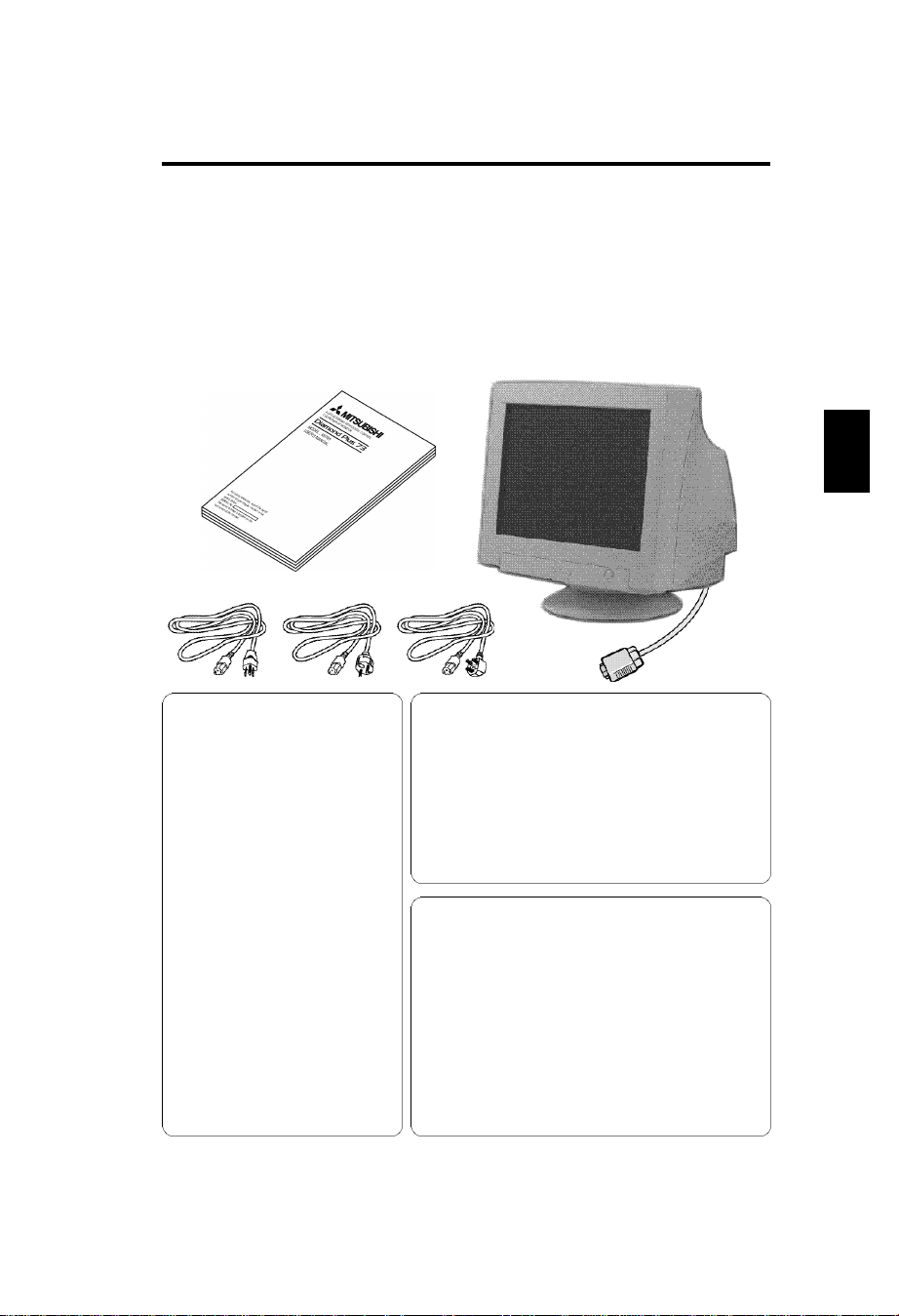
Contents
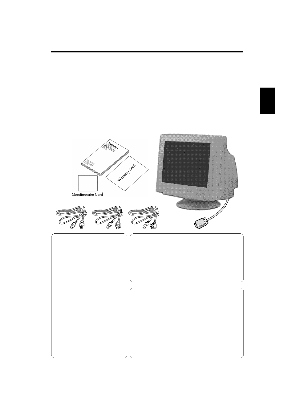
Monitor box* should contain the following:
* Remember to save your original box and packing material to transport
or ship the monitor.
* Complete and mail in warranty card. (for North America)
• Color Monitor Diamond Plus 73
• Warranty card (for North America)
• Questionnaire card (for North America)
• User‘s manual
• Power cord (Put only one Type)
UL/CSA (or) Europe (or) UK
MANUFATURER DECLARATION
FOR CE-MARKING:
We, NEC-Mitsubishi Electric Vi s u a l
Systems Corporation, declare under our
sole re s p o n s i b i l i t y, that this product is in
c o n f o rmity with the following standard s :
EN60950
EN55022(Class B)
EN61000-3-2
EN61000-3-3
EN55024
(IEC61000-4-2)
(IEC61000-4-3)
(IEC61000-4-4)
(IEC61000-4-5)
(IEC61000-4-6)
(IEC61000-4-8)
(IEC61000-4-11)
following the provisions of:
73/23/EEC Low Voltage Directive
89/336/EEC EMC Directive
The power cord provided with this monitor is
designed for safety and must be used with a properly
grounded outlet to avoid possible electrical shock.
Do not remove the monitor cabinet as this can expose
you to very high voltages and other hazards.
This product is not designed for use in life support
devices and
C o r p o r a t i o n
Life support devices are those devices which are used
to measure, diagnose, or evaluate the tissue, systems
or functions of the human body; or other devices
employed to support or sustain life or good health.
makes no representations to the contrary.
E
CAUTION
WARNING!
NEC-Mitsubishi Electric Visual Systems
E-1
Page 10

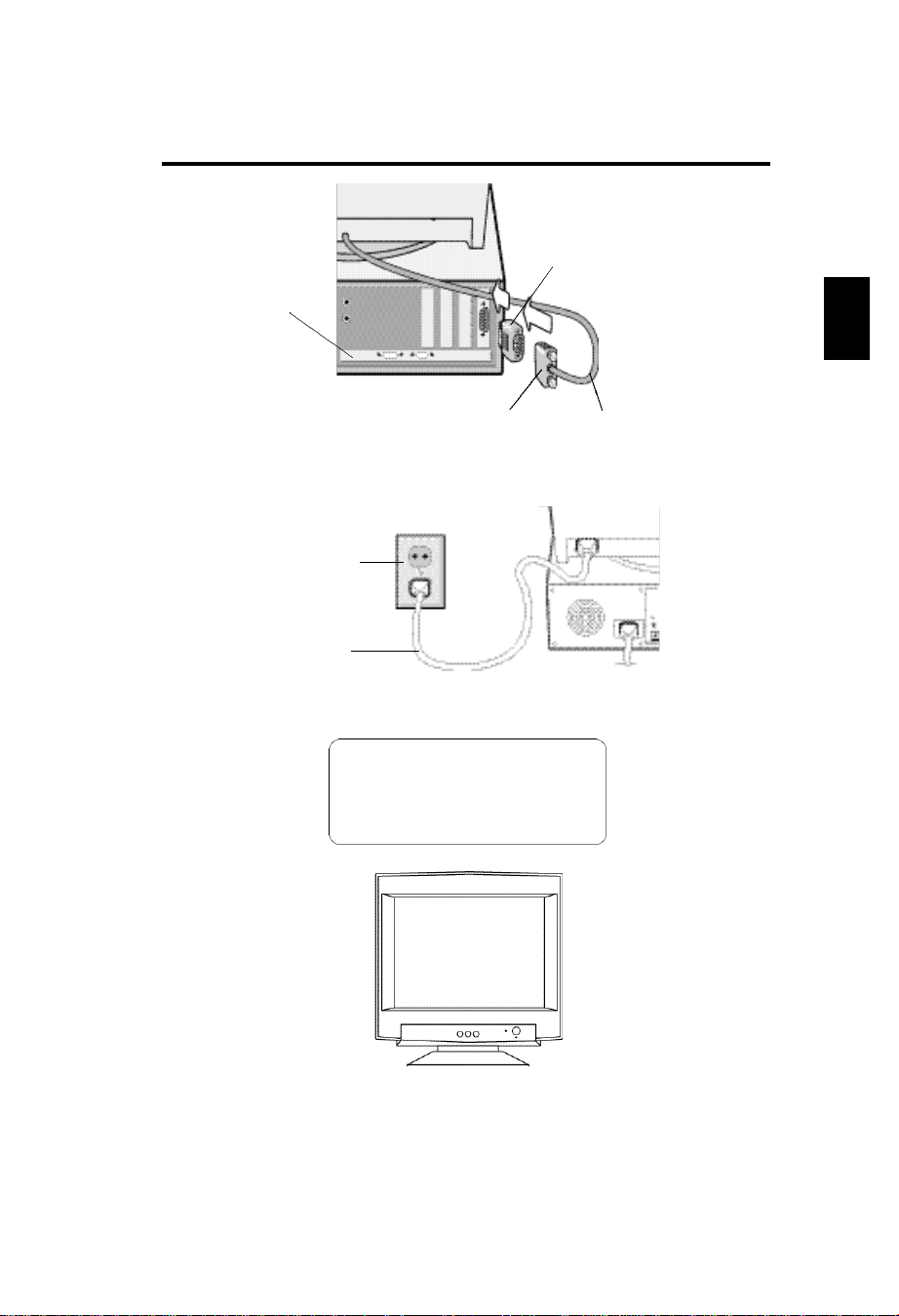
Quick Start
To attach the Monitor to your system, follow
these instruction:
1 Turn off the power to your computer and the monitor.
2 If necessary, install the display card. For more information, refer to the
display card manual.
3 For the PC: Connect the 15-pin mini D-SUB of the captive signal
cable to the connector of the display card in your system (Figure A.1)
Tighten all screws.
For the Mac: Connect the Macintosh Cable Adapter (not included)
to the monitor connector on the Macintosh (Figure B.1). Attach the 15pin mini D-SUB end of the captive signal cable to the Macintosh cable
adapter on the computer (Figure B.1). Tighten all screws.
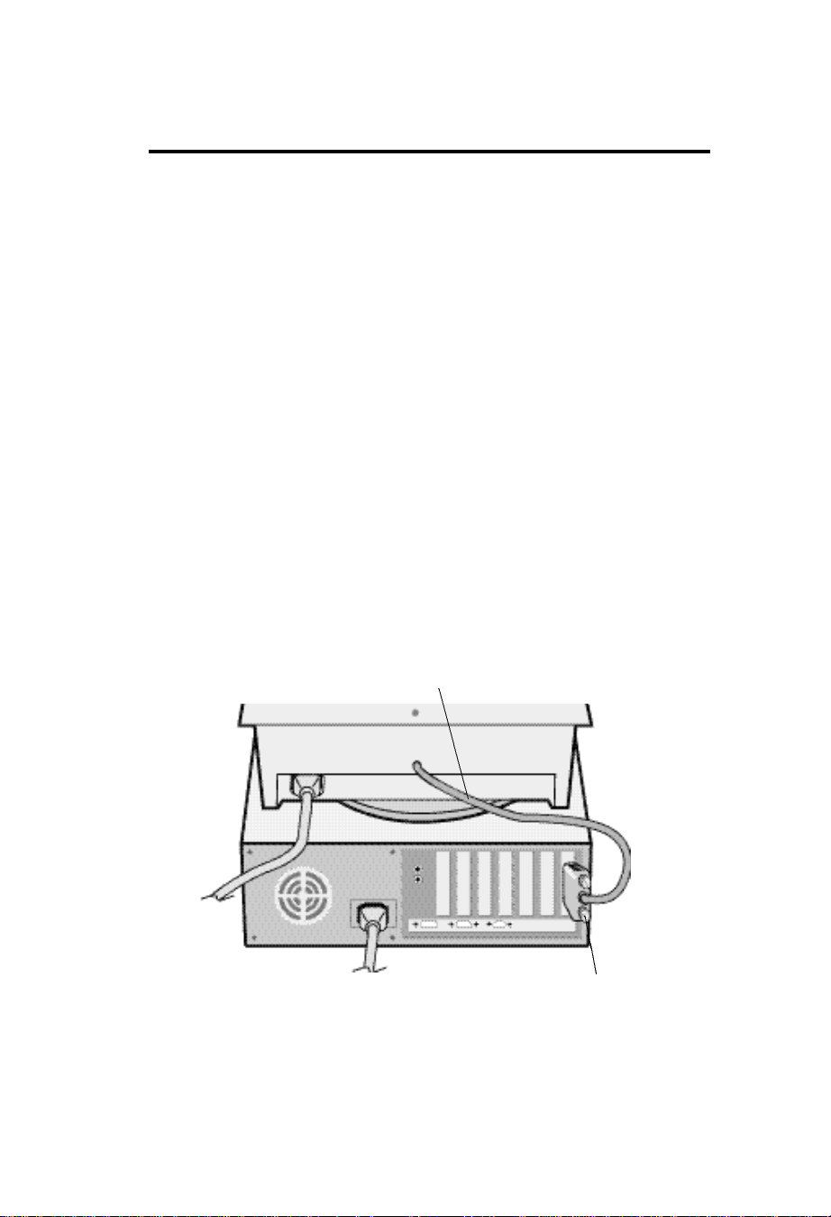
4 Connect one end of the power cord to the monitor and the other end to
the power outlet (Figure C.1).
5 Turn on the monitor (Figure D.1) and the computer.
6 This completes the installation.
NOTE: If you have any problems, please refer to the
Troubleshooting section of this User's Manual.
Captive Signal Cable
Figure A.1
E-2
15-pin-mini-D-SUB
Page 11
Computer
Mac Adapter
(not included)
*For Mac Adapter
contact your dealer
E
Power Outlet
Power cord
The socket-outlet shall be installed near
the equipment and shall be easily
accessible. During servicing, disconnect
the plug from the socket-outlet.
15-pin mini D-SUB
Figure B.1
Figure C.1
CAUTION:
Captive Signal Cable
Figure D.1
E-3
Page 12
Controls
OSD(On-screen Display) control buttons on the
front of the monitor function as follows:
SELECT Enters and exits the OSD menu.
-/+ Selects one of the controls and decreases or increases the
adjustment.
RESET Resets the highlighted control to the factory setting.
Press -/+ button at the same time for approximately 1 sec.
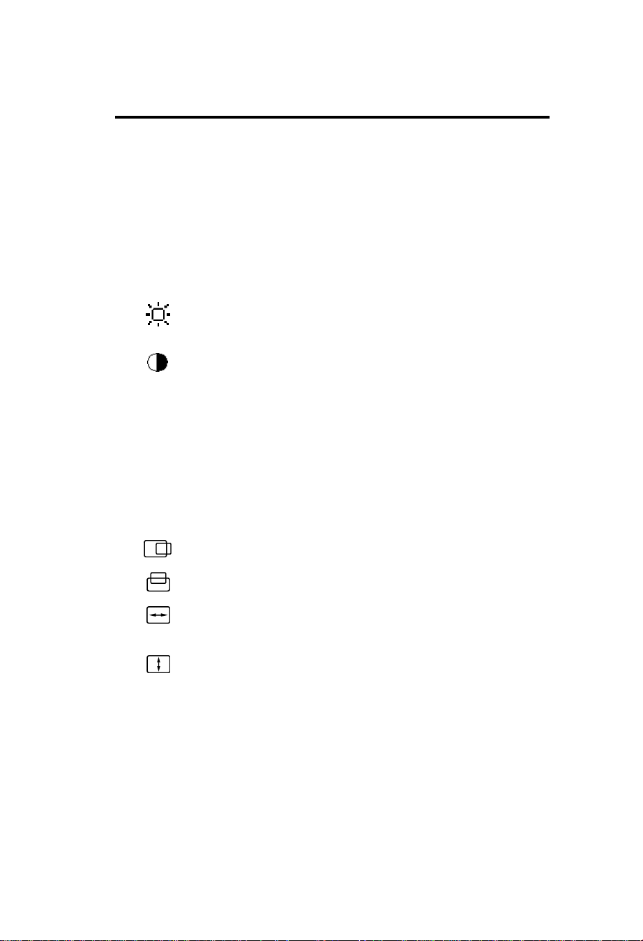
Brightness: Adjusts the overall image and background
screen brightness.
Contrast: Adjusts the image brightness in relation to the
background.(Contrast control is also effective with “-,+”
button even though OSD window is not visible.)
R Red Color Control: Adjust the red contrast of the display.
G Green Color Control: Adjust the green contrast of the
display.
B Blue Color Control: Adjust the blue contrast of the display.
Horizontal: Moves the image horizontally left or right.
Vertical position: Moves the image vertically up or down.
Horizontal size: Decreases or increases the horizontal size
of the image.
Vertical size: Decreases or increases the vertical size of the
image.
The Geometry controls allow you to adjust the curvature or angle of the
sides of your display.
E-4
Page 13
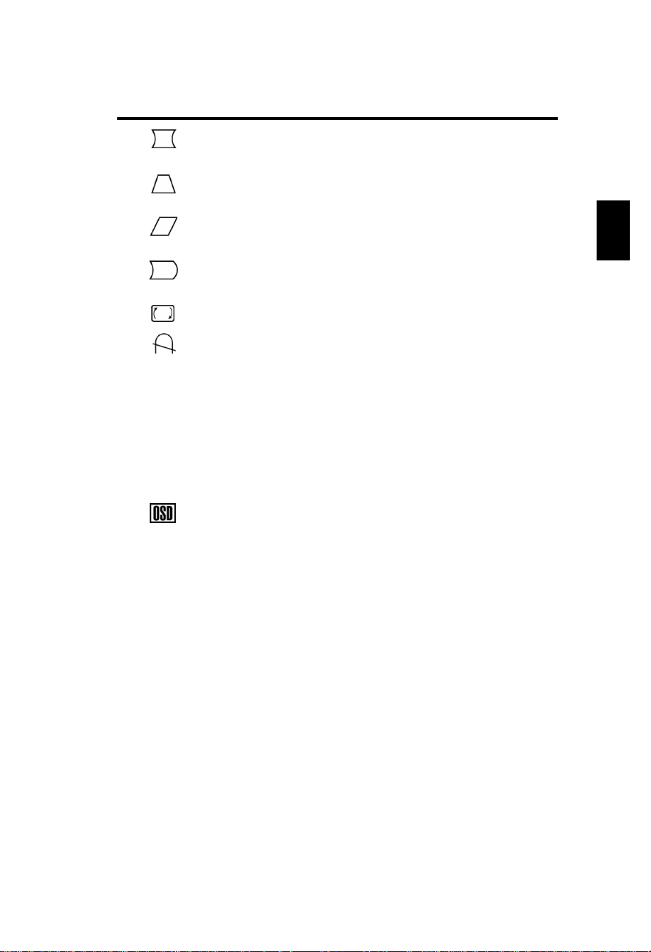
Pincushion/Barrel: Decreases or increases the curvature
of the sides either inward or outward.
Trapezoid: Decreases or increases the bottom of the screen
to be the same as the top.
Parallelogram: Decreases or increases the tilt of the sides
either to the left or right.
Bow (Pincushion Balance): Decreases or increases the
curvature of the sides either to the left or right.
Rotates: Rotates the image.
Degauss: Select the degauss icon on “Icon select window”
and push “SELECT” button.
It will eliminate the stray magnetic field and correct the scan
of the electron beam, which affect the purity, focus and
convergence.
Note: Allow a minimum interval of 20 minutes to elapse
between uses of the degauss function.
9300K Color Temperature: Select the Color Temperature icon on
“Icon Select Window” and push “SELECT” button.
OSD: There are 3 background colours (Blue, Black, and
white). These can be selected by “SELECT” button after the
selection of “OSD” on ”Icon select window”.
exit EXIT: To exit OSD window. Select EXIT on “Icon select
window”, then push “SELECT” button.
Note:If you do not push buttons within 10 seconds in OSD
condition, the window will automatically disappear.
E
E-5
Page 14
Recommended use
Safety Precautions and Maintenance
FOR OPTIMUM PERFORMANCE, PLEASE NOTE THE
FOLLOWING WHEN SETTING UP AND USING
THE COLOR MONITOR:
• DO NOT OPEN THE MONITOR. There are no user serviceable
parts inside and opening or removing covers may expose you to
dangerous shock hazards or other risks. Refer all servicing to
qualified service personnel.
• Use the monitor in a clean, dry area.
• Do not spill any liquids into the cabinet or use your monitor near
water.
• Do not insert objects of any kind into the cabinet slots, as the may
touch dangerous voltage points, which can be harmful or fatal or
may cause electric shock, fire or equipment failure.
• Do not place any heavy objects on the power cord. Damage to the
cord may cause shock or fire.
• Do not place this product on a sloping or unstable cart, stand or
table, as the monitor may fall, causing serious damage to the
monitor.
• Keep the monitor away from high capacity transformers, electric
monitors and other devices such as external speakers or fans, which
may create strong magnetic fields.
• If possible, position the monitor so that it is facing the east to
minimize the effects of the earth‘s magnetic field.
• Changing the direction of the monitor while it is powered on may
cause image discoloration. To correct this, turn the monitor off for 20
minutes before powering it back on.
• To separate the equipment from the power source you have to
remove the plug from the inlet socket.
• When operating the Diamond Plus 73 with its AC 220-240V
worldwide power supply, use a power supply cord that matches the
power supply voltage of the AC power outlet being used. The power
supply cord you use must have been approved by and comply with
the safety standards of your country.
Immediately unplug your monitor from the wall outlet and refer servicing
to qualified service personnel under the following conditions:
• When the power supply cord or plug is damaged.
• If liquit has been spilled, or objects have fallen into the monitor.
• If the monitor has been exposed to rain or water.
• If the monitor has been dropped or the cabinet damaged.
E-6
Page 15
• If the monitor does not operate normally by following operating
instructions.
• Allow adequate ventilation around the monitor so
that heat can properly dissipate. Do not block
ventilated openings or place them monitor near a
radiator or other heat sources. Do not put an thing
on top of monitor.
• The power cable connector is the primary means of
CAUTION
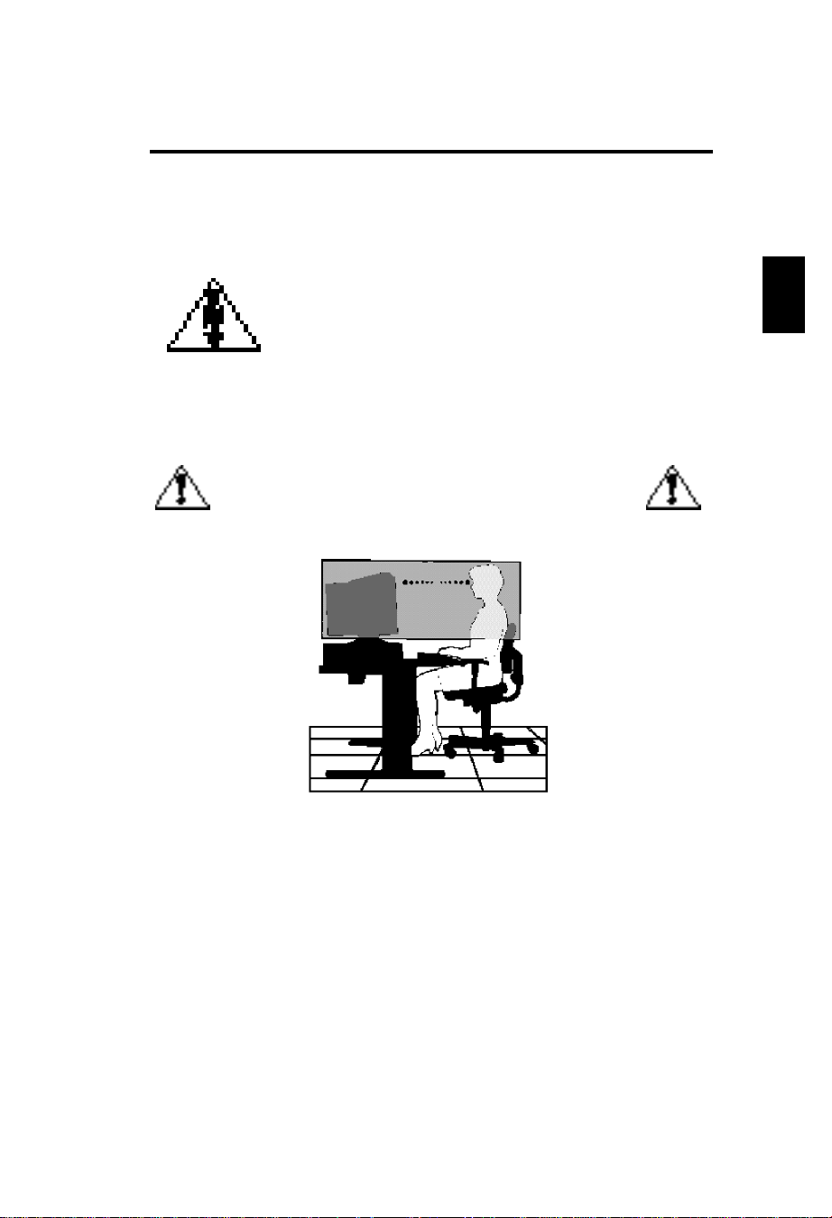
CORRECT PLACEMENT AND ADJUSTMENT OF THE
MONITOR CAN REDUCE EYE, SHOULDER AND NECK
FATIGUE. CHECK THE FOLLOWING WHEN YOU •
detaching the system from the power supply. The
monitor should be installed close to a power outlet
which is easily accessible.
• Handle with care when transporting.
Save packaging for transporting .
POSITION THE MONITOR:
E
• Adjust the monitor height so that the top of the screen is at or slightly
below eye level. Your eyes should look slightly downward when
viewing the middle of the screen.
• Position your monitor no closer than 40 cm and no further away
than 70 cm from your eyes. The optimal distance is 50 cm.
• Rest your eyes periodically by focusing on an object at least 6 m
away. Blink often.
• Position the monitor at a 90˚ Xangle to windows and other light
sources to minimize glare and reflections. Adjust the monitor tilt so
that ceiling lights do not reflect on your screen.
E-7
Page 16
• If reflected light makes it hard for you to see your screen, use an
anti-glare filter.
• Adjust the monitorís brightness and contrast controls to enhance
readability.
• Use a document holder placed close to the screen.
• Position whatever you are looking at most of the time (the screen or
reference material) directly in front of you to minimize turning your
head while you are typing .
• Get regular eye checkups.
Cleaning Your Monitor
When cleaning the monitor, please follow these guidelines:
• Always unplug the monitor before cleaning.
• Wipe the screen and cabinet front and sides with a soft cloth.
• If the screen requires more than dusting, apply a household window
cleaner to a soft cloth to clean the monitor screen.
• Do not use benzene, thinner or any volatile
substances to clean the unit as the finish may be
permanently marked.
• Never leave the monitor in contact with rubber or
vinyl for an extended time period.
CAUTION
• Do not spray directly on the screen as cleaner may
drip into the monitor and damage the circuitry.
• Never use an abrasive cleaner on the screen
surface as this will damage the anti-reflection
coating.
Ergonomics
To realize the maximum ergonomics benefits, we recommend the
following :
• Adjust the brightness until the background raster disappears .
• Do not position the contrast controls to its maximum setting .
• Use the preset size and position controls with standard signals .
• Use the preset color setting and sides Left / Right controls.
• Use non-interlaced signals with a vertical refresh rate between
75-120Hz.
• Do not use primary color blue on a dark background, as it is
difficult to see and may produce eye fatigue due to insufficient
contrast.
E-8
Page 17
Specifications
Monitor
Specifications
Picture Tube Diagonal :
Viewable Image Size:
Radius:
Input Signal Video:
Sync:
Display Colors Analog input:
Synchronization Horizontal:
Range Vertical:
Resolutions Supported
Resolution based on horizontal
and vertical frequencies only
Active Display Area Horizont:
(Factory setting) Vertical:
Active Display Area
(Full scan)
Power Supply
Current Rating
Dimensions
Weight
Environmental Considerations
Operating Temperature:
Humidity:
Altitude:
Storage Temperature:
Humidity:
Altitude:
Diamond Plus 73
Monitor
43cm(17inch)
41cm(16inch)
50000mm
ANALOG 0.7 Vp-p/75 Ohms
Separate sync. TTL Level
Horizontal sync. Positive/Negative
Vertical sync. Positive/Negative
Unlimited number of Colors
31kHz to 70kHz
55Hz to 120Hz
640 x 480 @60 to 120Hz
800 x 600 @55 to 110Hz
832 x 624 @55 to 105Hz
1024 x768 @55 to 87Hz....
1280 x 1024 @55 to 66Hz
310mm
232mm
325mm
243mm
AC 100-240V, 50-60Hz
1.5A @ 100-240V
403(W)x420(H)x420(D)mm
16.4kg
0˚C to +35˚C
30% to 80%
0 to 3000m
-20˚C to + 60˚C
10% to 90%
0 to 13700m
90˚ deflection, 0.25mm grille pitch,
medium short persistence phosphor,
aperture grille CRT, multi-layered, antistaticscreen coating, dark-tint screen.
Depends on the display card used.
Automatically
Automatically
Some systems may not support all
modes listed
Recommended resolution at 85 Hz for
optimal display performance.
Dependent upon signal timing used,
and does not include border area.
Dependent upon signal timing used,
and does not include border area.
Notes
E
NOTE: Technical specifications are subject to change without notice.
E-9
Page 18

Features
Flat Aperture Grille CRT:
Delivers an unparalleled viewing experience with a virtually flat image,
eliminating distortion and reducing glare so that what you see on-screen is
what you get on your printed output. The striped phosphor alignment of the
CRT delivers superior vertical definition with improved brightness for more
uniform image contrast.
Screen Surface
Reduces reflection and glare and increases contrast without sacrificing
focus level, clarity or brightness. Along with the flat square technology
CRT, a high contrast screen with 0.25 mm grille pitch delivers crisp, clean
text and graphics.
Dual Dynamic Beam Focus :
Provides precise, continuous focus adjustment of the electron beams and
optimum image quality, even to the far edge of the screen.
Color Control System: Allows you to change between five color
settings on your display to match your personal preference.
OSD(On-Screen Display) Controls: Allow you to quickly and
easily adjust all elements of your screen image via simple to use onscreen menus.
Ergonomice Features: Enhance human ergonomics to improve the
working environment, protect the health of the user and save money and
is compliant with TCO'99 and MPRII for lower emissions .
Plug and Play: The Microsoft
operating system facilitates setup and installation by allowing the monitor
to send its capabilities (such as screen size and resolutions supported)
directly to your computer, automatically optimizing display performance.
Power Management System: Provides innovative power-saving
methods that allow the monitor to shift to a lower power consumption
level when on but not in use, saving your monitor energy costs, reducing
emissions and lowering the air conditioning costs of the workplace and is
compliant with VESA DPMS and EPA ENERGY STAR®.
:
®
solution with the Windows®95/98
Mode LED Indicator Power Saving
On Green None
Off (IPM Mode) Orange Maximum(<5 Watts, Slow Recovery)
Off(Power Switch, Off) No Light No Power Used(Fully Off)
E-10
Page 19

Reduced Magnetic Field Technology: Reduces magnetic and
alternating electric field emissions and static electricity, addressing
ergonomic concerns regarding potential risks from extended computer
monitor use and is compliant with MPRII and TCO‘99.
Multiple Frequency Technology: Automatically adjusts monitor
to the display card‘s scanning frequency, thus displaying the resolution
required.
FullScan Capability: Allows you to use the entire screen area in
most resolutions, significantly expanding image size.
E
E-11
Page 20

Troubleshooting
No Picture
• The display card should be completely seated in its slot.
• Power Switch and computer power switch should be in the ON
position.
• The signal cable should be completely connected to the display
card/computer.
• Check the connector for bent or pushed-in pins.
Image is scrolling or unstable
• Signal cable should be completely attached to the computer.
• Check the pin assignment and signal timing of your monitor and
display card with respect to the recommended timing and pin
assignment .
• If the MAC adapter is used, check for proper connection or make
sure the display card is MAC compatible and that the card is
properly seated in the computer.
LED on the monitor is not lit
(no green or orange color can be seen)
• Power Switch should be in the ON position and the power cord
should be connected.
Picture is fuzzy or Color looks blotchy
• Adjust the Brightness and Contrast Controls.
• Access the Degauss Control through OSD.
Activate the Degauss Control.
CAUTION: A minimum interval of 20 minutes should exist before the
Degauss Function is used a second time.
P i c t u re bounces or a waving pattern is present in the picture
• Move electrical devices that may be causing electrical interference
away from the monitor.
Edges of the display image are not square
• Use the OSD Geometry Controls to straighten the edges.
• If possible, position the front of the monitor facing east.
Display image is not centered, too small, or too large
• Use the OSD Size and Position controls to adjust the image.
E-12
Page 21
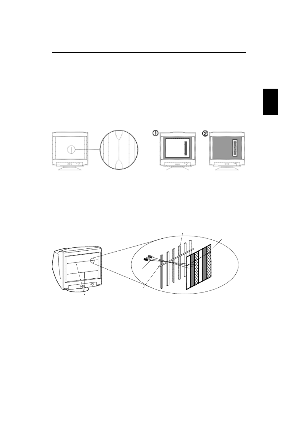
Black vertical lines are visible on the screen
• Thin vertical black lines on one or both sides of the screen. This
minor condition is caused by grille element overlap which can occur
during shipping.
• Position an open white window over the affected area of the screen
and maximize the brightness and contrast controls. This will cause
localized heating of the overlap which will clear in a few minutes. Be
sure to readjust the brightness and contrast controls back to the
normal viewing level after this procedure.
Two fine horizontal lines are visible on the screen
• The 2 very faint thin lines across the screen are normal. They are
caused by the aperture grille stabilization filaments(Damper
Wires)which are required for all aperture grille CRTs'.
E
Shadow of Damper Wires
Aperture Grille
Electron Gun
Damper Wires
Aperture Grille Type
Shadow of
Damper Wires
A buzzing sound when power on
• A brief vibration or hum sound that is heard just after power up is
normal. This is caused by the automatic degaussing function. This
sound will be heard each time the monitor is powered up from a
cold start and each time the manual degauss button is used.
E-13
Page 22

Röntgenstrahlung
Die in diesem Gerät erzeugten Röntgenstrahlen sind durch die
eigensichere Kathodenstrahlröhre ausreichend abgeschirmt.
Unsachgemäße Eingriffe, insbesondere Verändern der Hochspannung
oder Einbau eines anderen Bildröhrentyps, können dazu führen, daß
Röntgenstrahlung in erheblicher Stärke auftritt. So veränderte Geräte
entsprechen nicht mehr dieser Zulassung und dürfen nicht betrieben
werden.
Page 23
Lieferumfang
Monitor Karton* sollte folgendes enthalten sein:
* Bewahren Sie die Originalverpackung für einen möglichen Transport
oder Versand des Geruätes unbedingt auf.
• Monitor
• Bedienerhandbuch
• Netzkabel
UL/CSA (oder) Europa (oder) UK
D
KONFORMITÄTSERKLÄRUNG
ZUR CE-KENNZEICHUNUNG:
Wi r, NEC-Mitsubishi Electric Vi s u a l
Systems Corporatation, erklären in
alleiniger Verantworlung, daß das
P rodukt auf das sich diese Erkläru n g
bezieht, mit der/den folgenden
N o rmen oder norm a t i v e n
Dokumenten übere i n s t i m m t :
Gemäß den Bestimmungen der
R i c h t l i n i e n :
7 3 / 2 3 / E E C
N i e d e r s p a n n u n g s r i c h t l i n i e
89/336/EEC EMV Richtlinie
HERSTELLER-
EN60950
EN55022(Klasse B)
E N 6 1 0 0 0 - 3 - 2
E N 6 1 0 0 0 - 3 - 3
EN55024
(IEC61000-4-2)
(IEC61000-4-3)
(IEC61000-4-4)
(IEC61000-4-5)
(IEC61000-4-6)
(IEC61000-4-8)
(IEC61000-4-11)
ACHTUNG
Das mitgelieferte Netzkabel wurde konzipiert, um
größtmögliche Sicherheit zu gewährleisten. Es darf
nur an eine ordnungsgemäß geerdete Steckdose
angeschlossen werden, um eventuelle Stromschläge
zu vermeiden.
Entfernen Sie nie die Rückwand dieses Gerätes, da
Sie sich dadurch sehr hohen Spannungen und
anderen Gefahren aussetzen können.
ACHTUNG!
Dieses Produkt ist nicht für den Gebrauch in
Zusammenhang mit lebenserhaltenden Geräten
geeignet und die NEC-Mitsubishi Electric Visual Systems
C o r p o r a t a t i o n macht keinerlei gegensätzliche
Darstellungen. Lebenserhaltende Geräte sind solche,
die zum Messen, Diagnostizieren oder für die
Auswertung von Gewebe, Systemen oder Funktionen
des menschlichen Körpers benutzt werden; oder
andere Geräte die angewendet werden, um das
Leben oder die Gesundheit zu unterstützen oder zu
erhalten.
D-1
Page 24
Inbetriebnahme
Beim Anschluß eines Monitors an Ihren Computer
sind folgende Punkte zu beachten:
1 Schalten Sie die Stromversorgung von Computer und Monitor aus.
2 Falls notwendig, installieren Sie eine Grafikkarte nach den
Anweisungen im Benutzerhandbuch der Grafikkarte.
3 Für den PC: Verbinden Sie den 15-pin mini D-SUB Stecker des fest
montierten Signalkabels mit der entsprechenden Buchse der
Grafikkarte Ihres Rechners (Abbildung A.1). Ziehen Sie alle Schrauben
fest.
Für den Macintosh: Stecken Sie den Macintosh Signaladapter
(Option) auf die entsprechende Buchse der Grafikkarte des Macintosh
(Abbildung B.1). Stecken Sie den 15-pin mini D-SUB Stecker des fest
montierten Signalkabels auf den Adapter am Rechner (Abbildung B1).
Ziehen Sie alle Schrauben fest.
4 Verbinden Sie das mitgelieferte Netzkabel auf einer Seite mit dem
Monitor und auf der anderen Seite mit einer geerdeten Wandsteckdose
in der Nähe des Monitor (Abbildung C.1).
5 Schalten Sie Monitor (Abbildung D.1) und Computer ein.
6 Hiermit ist der Anschluß des Monitors abgeschlossen.
Hinweis: Sollten sich hierbei Probleme ergeben, so lesen Sie bitte den
Abschnitt “Hilfe bei Problemen”.
Fest montiertes Signalkabel
15-pin mini D-SUB
Abbildung A.1
D-2
Page 25

Computer
Mac Adapter
(optional erhältlich)
15-pin mini D-SUB
Abbildung B.1
Wandsteckdose
Netzkabel
Abbildung C.1
Achtung
Die Stromversorgung dieses Monitors bleibt auch bei ausgeschaltetem Gerät
aktiv. Daher sollte sich die Netzsteckdose in der Nähe des Gerätes befinden
und leicht zugänglich sein.
Fest montiertes Signalkabel
D
Abbildung D.1
D-3
Page 26

Bedientasten
Die OSD(On-screen Darstellbare) Tasten, an der
Vorderseite des monitor, haben folgende Funktionen:
SELECT Beginn und Ende des OSD Menüs.
-/+ Selektiert eine der OSD-Funktionen und verringert bzw.
erhöht den markierten Parameter im Adjustment.
RESET Setzt den aktuellen markierten Parameter auf
Werkseinstellung zurück. Drücken Sie den -/+
Knopfgleichzeitig für ungefähr eine Sekunde.
Helligkeit: Erlaubt die Einstellung der generellen Bild-und
Hintergrundhelligkeit.
Kontrast: Ändert die Helligkeit des Bildinhaltes im Verhältnis
zum Bildhintergrund. (Obwohl das OSD Fenster nicht
vorhanden ist, kann die Kontraststeuerung mit den Knöpfen “,+” benutzt werden)
R Red Colour Control: Erlaubt eine individuelle Anpassung
des roten Farbanteiles.
G Green Colour Control: Erlaubt eine individuelle
Anpassung des grünen Farbanteiles.
B Blue Colour Control: Erlaubt eine individuelle Anpassung
des blauen Farbanteiles.
Horizontale Position: Bewegt das Bild horizontal nach
links oder rechts.
Vertikale Position: Bewegt das Bild vertikal nach oben
oder unten.
Horizontale Größe: Ändert die Breite der Abbildung.
Vertikale Größe: Ändert die Höhe der Abbildung.
Die Geometrie-Einstellungen ermöglichen Ihnen die Krümmung oder die
Neigung der Bildseite zu justieren.
Kissenentzerrung: Justiert die Krümmung der Bildseiten
nach innen oder außen.
D-4
Page 27

Trapez: Justiert die Breite des oberen Bildrandes gleich der
Breite des unteren Bildrandes.
Parallel: Justiert die Neigung der Bildseiten nach links oder
rechts.
Tonnen-Verzerrung: Justiert die Krümmung der Bildseiten
nach links oder rechts.
Drehen: Erlaubt eine Drehung des Bildes.
Entmagnetisierung: Wählen Sie das “Degauss” Icon im
“Icon-select-Fenster” und drücken Sie “SELECT”. Entfernt sich
aufbauende Magnetfelder, die den korrekten Weg des
Elektronenstrahl behindern und so Farbreinheit, Konvergenz
und Schärfe negativ beeinflussen.
Anmerkung: Z wischen jedem erneuten Betätigen der
Funktion sollten mindestens 20 Minuten verstreichen.
9300K Farbtemperatur: Wählen Sie das Farbtemperatur Icon im
“lcon-select-Fensterüc und drücken Sie I“SELECT”.
OSD: Es gibt 3 Hintergrundfarben (blau, schwarz und weiß).
Diese können nach der Wahl von “OSD” im “Icon-selectFenster” mit “SELECT” gewählt werden.
exit EXIT: Verlassen des OSD Fensters. Wählen Sie “EXIT” im
“Icon-select-Fenster” und drücken dann “SELECT” um das
OSD Fenster zu verlassen.
D
Anmerkung:Wenn Sie lähger als 10 Sekunden keinen
Knopf im OSD-Men¸ betätigen, verschwindet das Fenster
automatisch.
D-5
Page 28

Aufstellen
Sicherheitsvorkehrungen und Vorschriften.
UM EINE OPTIMALE ABBILDUNGSQUALITÄT IHRES
MULTISYNC V SERIE FARBMONITORS ZU
GEWÄHRLEISTEN; SOLLTEN SIE FOLGENDE PUNKTE
BEI DER AUFSTELLUNG UND BENUTZUNG DES
MONITORS BEACHTEN:
• ÖFFNEN SIE DEN MONITOR NICHT. Im Inneren des Gerätes
befinden sich keine Teile, die vom Benutzer selbst gewartet werden
können. Um einen Stromschlag oder andere Verletzungen zu
vermeiden, sollte das Gerät nicht geöffnet werden. ‹berlassen Sie
sämtliche Wartungsarbeiten ausschließlich qualifiziertem ServicePersonal.
• Benutzen Sie den Monitor nur in einer trockenen, sauberen
Umgebung.
• Vermeiden Sie das Eindringen von Flüssigkeiten in das Gehäuse und
benutzen Sie den Monitor nicht in der Nähe von Wasser.
• Stecken Sie keinerlei Gegenstände in das Gerät. Diese könnten
gefährliche Spannungspunkte im Geräteinneren berühren und einen
Stromschlag, Brand oder Fehlfunktionen des Gerätes verursachen.
• Stellen Sie keine schweren Gegenstände auf das
Netzkabel.Beschädigte Netzkabel können zu Brand oder
Stromschlag führen.
• Stellen Sie dieses Gerät nicht auf einer unebenen, instabilen
Unterlage auf. Der Monitor können herunterfallen und schwer
beschädigt werden.
• Plazieren Sie Ihren Monitor nicht in der Nähe von Elektromotoren
oder anderen Geräten wie z. B. externe Lautsprecher oder Lüfter, die
starke elektromagnetische Felder erzeugen können.
• Nach Möglichkeit sollten Sie den Monitor nach Osten zeigend
aufstellen, um die Wirkungen der Erdmagnetfelder zu minimieren.
• Eine Änderung des Aufstellungsortes bei eingeschaltetem Monitor
kann zu Verfärbungen bei der Bilddarstellung führen. Um dies zu
korrigieren, mufl im OSD die Funktion “Entmagnetisieren” aktiviert
werden, die diese Verfärbungen aufhebt.
• Zur vollständigen Trennung vom Stromnetz ist der Netz- bzw.
Gerätestecker zu ziehen.
D-6
Page 29

• Der Diamond Plus 73 ist mit einem für den weltweiten Einsatz
geeigneten 220-224V Netzteil ausgerüstet. Verwenden Sie ein
geeignetes Netzkabel, um das Gerät mit der lokal verwendeten
Netzsteckdose zu verbinden. Das verwendete Netzkabel, muß
geprüft sein und den in Ihrem Land geltenden
Sicherheitsbestimmungen entsprechen.
In den folgenden Fällen muß der Monitor sofort vom Netz getrennt
werden und ein Service-Techniker hinzugezogen werden:
• Wenn das Netzkabel oder der Netzstecker beschädigt sind.
• Wenn Flüssigkeit über dem Gerät verschüttet wurde, oder
Gegenstände in den Monitor gelangten.
• Wenn der Monitor Regen ausgesetzt war oder mit Wasser in
Berührung kam.
• Wenn der Monitor fallengelassen oder das Gehäuse beschädigt
wurde.
• Wenn der Monitor trotz Aufstellung und Bedienung gemäß
Bedienungsanleitung nicht ordnungsgemäß funktioniert.
• Achten Sie auf eine ausreichende RundumBelüftung des Monitor, damit die Wärme richting
entweichen kann. Lüftungsschlitze im Gehäuse
dürfen nicht blockiert sein. Der Monitor sollte nicht
in der Nähe einer Heizung oder sonstiger
VORSICHT
Wärmequellen aufgestellt werden. Stellen sie keine
Gegenstände auf den Monitor.
• Der Netzstecker ist das vorrangige Mittel zum
Trennen des Monitors vom Spannungsnetz. Der
Monitor sollte in der Nähe einer leicht
zugänglichen Netzsteckdose installiert werden.
• Transportieren Sie den Monitor mit äußerster
Vorsicht. Bewahren Sie das Verpackungsmaterial
für einen erneuten Transport auf.
D
DAMIT AUGEN; NACKEN- UND
SCHULTERMUSKULATUR BEIM ARBEITEN AM
BILDSCHIRM ENTLASTET WERDEN, BEACHTEN SIE
BEIM AUFSTELLEN IHRES MONITORS BITTE DIE
NACHFOLGENDEN HINWEISE:
D-7
Page 30

• Stellen sie die Höhe des Monitors so ein, daß sich der obere Rand
des Bild-schirms in Augenhöhe oder etwas tiefer als Augenhöhe
befindet. Ihre Augen sollten leicht nach unten blicken, wenn Sie auf
die Bildschirmmitte sehen.
• Der Abstand vom Auge zum Monitor sollte nicht weniger als 40cm
und nicht mehr als 70 cm betragen. Der optimale Abstand beträgt
50 cm.
• Entspannen Sie Ihre Augen regelmäßig durch Fixieren eines
Gegenstandes in mindestens 6m Abstand. Öffnen und Schließen Sie
Ihre Augen mehrmals.
• Stellen Sie den Monitor in einem Winkel von 90˚ zum Fenster und
anderen Lichtquellen auf, damit Blendungen und Reflexionen auf
dem Bildschirm soweit wie möglich vermieden werden. Stellen Sie
den Schwenk-/Neigefuß Ihres Monitors so ein, daß durch
Deckenbeleuchtung verursachte Spiegelungen auf dem Bildschirm
vermieden werden.
• Wenn reflektierendes Licht es Ihnen erschwert, Ihren Bildschirm zu
erkennen, benutzen Sie einen zusätzlichen Anti-Reflektionsfilter. (Im
Computer-Zubehörhandel erhältlich)
• Stellen Sie die Helligkeit und den Kontrast so ein, daß die Lesbarkeit
des Bildschirminhalts verbessert wird.
• Bringen Sie in der Nähe des Monitors einen Vorlagenhalter an.
• Stellen das, worauf Sie die meiste Zeit blicken (den Bildschirm oder
das Referenzmaterial) direkt vor sich, damit Kopfbewegungen
während des Tippens minimiert werden.
• Lassen Sie Ihre Augen regelmäßig untersuchen.
D-8
Page 31

Reinigung Ihres Monitors
Beachten Sie bei der Reinigung Ihres Monitors bitte folgende Hinweise:
• Ziehen Sie vor der Reinigung immer den Netzstecker aus der
Steckdose.
• Reinigen Sie den Bildschirm und das Gehäuse mit einem weichen
Tuch.
• Verwenden Sie bei einer stärkeren Verschmutzung des Bildschirms
ein weiches Tuch mit Haushalts-Fensterreiniger für die Reinigung.
• Reinigen Sie das Gerät nicht mit Benzol,
Verdünnern oder anderen flüchtigen Stoffen, da die
Oberfläche durch diese Stoffe beschädigt werden
könnte.
• Vermeiden Sie längeren Kontakt mit Gummi- oder
Vinylprodukten.
VORSICHT
• Sprühen Sie Reinigungsmittel niemals direkt auf den
Monitor, da übermäßige Flüssigkeit in den Monitor
eindringen und zu Schäden führen könnte.
• Benutzen Sie niemals ein Scheuermittel auf der
Bildröhrenoberfläche, da dies zur Beschädigung
der Anti-Reflexionsbeschichtung führt.
Ergonomics
Aus ergonomischebn Gründen empfehlen wir folgendes:
• Stellen Sie die Helligkeit der Bildröhre so ein, daß das
Hintergrundraster der Röhre nicht sichtbar ist.
• Bringen Sie die Kontrasteinstellung nicht auf ihren maximalen Wert.
• Benutzen Sie die Standardeinstellungen für Bildlage und Bildgröße.
• Benutzen Sie die Standardeinstellung für die Farbeinstellung und die
Kissenentzerrung.
• Benutzen Sie Non-Interlaced-Signale mit einer Vertikalfrequenz
zwischen 75 bis 120 Hz .
(abhänging vom Treiber des Grafikkartenherstellers)
• Arbeiten Sie nicht mit der Primärfarbe Blau auf dunklem
Hintergrund. Der mangelnde Kontrast erschwert die Lesbarkeit der
Abbildung und strapaziert die Augen sehr stark.
D
D-9
Page 32

Technische Daten
Technische Daten
des Monitor
Bildröre Diagonal :
Sichtbarer Bildgröße:
Radius:
Eingangssignal Video:
Sync:
Darstellbare Farben Analoges
Eingangssignal:
Synchronisation Horizontal:
Vertikal:
Unterstützte Auflösungen
Auflösungen, ausschließlich
basierend auf
Horizontalen und vertikalen
Frequenzen.
Nutzbare Bildfläche Horizonat:
(Werksvoreinstellung) Vertikal:
Nutzbare Bildfläche
(Full scan)
Nennspannung
Nennstrom
Abmessungen
Gewicht
Betriebs- und Lagerbedingungen
Betriebs-Temperatur:
Feuchtigkeit:
Höe:
Lager-Temperatur:
Feuchtigkeit:
Höe:
Diamond Plus 73
Anmerkungen
Monitor
43cm(17inch)
41cm(16inch)
50000mm
ANALOG 0.7 Vp-p/75 Ohms
Separate sync. TTL Pegel
Horizontal sync. Positive/Negativ
Vertical sync. Positiv/Negativ
Unbegrenzte Anzahl von Farben Hängt von der Grafikkarte ab
31kHz bis 70kHz
55Hz bis 120Hz
640 x 480 @60 bis 120Hz
800 x 600 @55 bis 110Hz
832 x 624 @55 bis 105Hz
1024 x768 @55 bis 87Hz....
1280 x 1024 @55 bis 66Hz
310mm
232mm
325mm
243mm
AC 100 -240V, 50-60Hz
1.5 A@100 - 240V
403(B)x420(H)x420(T)mm
16.4kg
0˚C bis +35˚C
30% bis 80%
0 bis 3000m
-20˚C bis +60˚C
10% bis 90%
0 bis 13700m
90° Ablenkung, 0,25 mm grille pitch,
mittel/kurz nachleuchtender Phosphor,
flache Bildröhre mit Streifenmaske,
mehrschichtige antistatische
Bildschirmoberflächenvergütung, darktint screen.
Automatisch
Automatisch
Nicht alle Computersysteme
unterstützen die aufgeführten Modi.
Für beste Bildqualität eine
Bildwiederholrate von 85Hz bei der
empfohlenen Auflösung zu verwenden.
Die nutzbare Bildfläche hängt vom
Signaltiming ab.
Die nutzbare Bildfläche hängt vom
Signaltiming ab.
NOTE: Technische Änderungen vorbehalten.
D-10
Page 33

Merkmale
Flache Bildröhre mit Streifenmaske:
Liefert ein total flaches Bild, welches Verzerrungen und Spiegelungen
eliminiert. Was Sie auf dem Bildschirm sehen, erhalten Sie auf dem
Ausdruck. Der in Streifen angeordnete Phosphor liefert höchste vertikale
Genauigkeit mit verbesserter Helligkeit für mehr gleichförmigen Kontrast
des Bildes.
Bildschirmoberfläche :
Reduziert Reflexionen und Blendung und erhöht den Kontrast ohne
Einbußen an Schärfe, Klarheit oder Helligkeit. In Kombination mit der
Flat-Square-Technologie sorgt ein kontraststarker Bildschirm mit 0,25 mm
grille pitch für eine brillante und scharfe Darstellung von Text und Bild.
Zweifache dynamische Strahlfokussierung :
Die zweifache dynamische Strahlfokussierung reguliert dynamisch den
Fokus jedes Elektronenstrahls über die gesamte Fläche der Bildröhre
hinweg. So erhalten Sie selbst in den äußerten Ecken des Bildschirmes die
beste Bildqualität in punkto Schärfe und Klarheit der Abbildung.
Farbtemperaturkontrolle:
Erlaubt die Auswahl zwischen 5 verschiedenen Farbeinstellungen.
OSD (On-Screen Darstellbare) Menü: Erlaubt leichte und
schnelle Einstellung aller Eigenschaften der Bilddarstellung des Monitors
über das OSD-Men.
Ergonomie: Verbesserung der Ergonomie und damit Verbesserung
der Arbeitsplatzumgebung, Gesundheitsvorsorge und Einhaltung der
Emissionswerte gemäß den Standards TCO'99 und MPRII für geringe
Emissionswerte.
Plug and Play: Die Lösung von Microsoft
Windows®98 Betriebssystem. Vereinfacht die Installation eines neuen
Monitors, da der Monitor nach Abfrage seine Leistungsdaten (wie z. B.
Auflösungen und Bildwiederholraten) an das Betriebssystem sendet.
Entsprechend wird die Bildschirmdarstellung automatisch optimiert.
Power Management System: Erlaubt die Steuerung von Strom-
sparfunktionen im Monitor, wenn dieser nicht verwendet wird, was sich in
Energiekosteneinsparung sowie reduzierten Wärme- und
Strahlungsemissionen auswirkt. Diese Funktion entspricht den Standards
nach VESA DPMS und EPA ENERGY STAR®.
®
im Windows®95 und
D
D-11
Page 34

Mode Farbe Stromeinsparung
On Grün Keine
Off Orange Maximum(<5 Watts)
Ausgeschaltet aus (dunkel) Kein Stromverbrauch (ausgeschaltet)
Reduzierte Magnetfeldeinflüsse: Reduziert wurden sowohl
magnetische als auch elektrische Felder sowie die statische Elektrizität,
um erhöhten ergonomischen Ansprüchen bei Dauernutzung eines
Computermonitors zu genügen. Alle Eigenschaften entsprechend den
Standards MPRII und TCO‘99.
Multifrequenztechnik: Der Monitor wird automatisch an die von
einer Grafikkarte ausgegebenen Zeilen- und Bildfrequenzen angepaßt.
Damit wird immer die gewünschte Auflösung dargestellt. (Leistungsgrenze
des Monitors beachten)
Full Scan Darstellung: Erlaubt die Nutzung der vollen aktiven
Bildschirmfläche in den meisten Auflösungen.
D-12
Page 35

Hilfe bei Problemen
Kein Bild
• Überprüfen Sie den festen Sitz der Grafikkarte.
• Die Netzschalter von Monitor und Computer müssen in Stellung ON
stehen.
• Das Signalkabel muß fest mit dem Ausgang der Grafikkarte
verbunden sein.
• Prüfen Sie den Anschlußstecker auf verbogene Steckkontakte.
Das Bild läuft in horizontaler oder vertikaler Richtung
• Das Signalkabel muß vollständing in den Computer eingesteckt
werden.
• Prüfen Sie die Steckerzuordnung und die Signalkompatibilität des
Monitors und Ihrer Grafikkarte hinsichtlich der empfohlenen
Kompatibilität und Steckerzuordnung.
• Wenn der MAC Adapter verwendet wird, üBerprüfen Sie, ob der
Anschluß korrekt ist und vergewissern Sie sich, daß die Videokarte
MAC-kompatibel ist und dafl die karte im Computer korrekt
eingesteckt ist.
Die Netz LED leuchtet nicht (nicht grün oder orange)
• Bringen Sie den Netzschalter des Monitors in die ON-Position und
prüfen Sie die korrekte Installation des Netzkabels.
Das Bild ist verschwommen oder die Farbe sieht fleckig aus.
• Justieren Sie Kontrast und Helligkeit.
• Betätigen Sie die Entmagnetisierungs Funktion.
ACHTUNG: Warten Sie ca. 20 Minuten bevor Sie diese Funktion erneut
ausführen.
Abbildung ist verzerrt
• Entfernen Sie Geräte, die ein elektromagnetisches Feld in der Nähe
des Monitors erzeugen.
Ecken der Abbildung sind nach innen oder außen gewölbt.
• Justieren Sie die Kissenentzerrung über das OSD-Menü.
• Wenn möglich richten Sie die Monitor-Oberfläche nach Osten aus.
Das Bild ist nicht mittig, zu klein oder zu groß.
• Nutzen Sie die OSD-Regler zur Einstellung von vertikaler und
horizontaler Größe und Lage der Abbildung.
D
D-13
Page 36

Schwarze vertikale Linien sind auf dem Bildschirm
sichtbar
• Auf dem Bildschirm erscheinen auf einer oder beiden Seiten dünne
schwarze vertikale Linien.Dieses Bild wird durch eine Überlappung
der Streifen während des Transports verursacht.
• Sollte dies nicht zum Erfolg führen, positionieren Sie ein weißes
Fenster über die betroffene Stelle und stellen Sie die Helligkeits- und
Kontrastkontrollen auf ihre Maximalwerte. Dadurch wird die
Überlappung in wenigen Minuten beseitigt. Die Helligkeits- und
Kontrastwerte müssen nach diesem Vorgang wieder auf den
Normalwert reduziert werden.
Zwei feine horizontale Linien sind auf dem
Bildschirm sichtbar
• Diese beiden feinen horizontalen Linien stellen keinen Defekt dar,
sondern sind für Streifenmasken normal. Bei diesen feinen Linien
handelt es sich um die Schatten der Stabilisierungsdrähte, die bei
allen Streifenmasken-Bildröhren zur Stabilisierung der Maske
verwendet werden.
Elektronenkanone
Streifenmaske
Schatten der
stabilisierungsdrähte
Stabilisierungsdrähte
Schatten der stabilisierungsdrähte Aufbau der streifenmasken Bildröher
Surrendes Geräusch beim Einschalten des Gerätes
• Ein kurzes Vibrieren oder Summen nach dem Einschalten ist normal.
Dies wird durch die automatische DEGAUSS-Funktion verursacht.
Dieses Geräusch tritt immer bei einem Kaltstart und bei Drücken der
DEGAUSS-Taste auf.
D-14
Page 37

Contenu de l‘emballage
Contenu de l‘emballage* de votre moniteur:
* Ne pas oublier de conserver tous les emballages d‘origine pour
transporter ou pour expédier le moniteur.
• Moniteur couleur
• Manuel d‘utilisation
• Un Câble d‘alimentation
(Mettre seulement un type)
UL/CSA (ou) Léurope (ou) Royaume Uni
DÉCLARATION DE
CONFORMITÉ POUR
MARQUAGE CE:
N o u s ,NEC-Mitsubishi Electric Vi s u a l
Systems Corporatation,
n o l re seule responsabililé que le pro d u i t
auquel se rétére celte déclaration est
c o n f o rme a la aux normes ou autre s
documents norm a t i f s :
c o n f o rmément aux dispositions de
D i re c t i v e s :
73/23/EEC Lage-netspanningsrichtlijn
89/336/EEC EMC-richtlijn
EN60950
EN55022(Classe B)
E N 6 1 0 0 0 - 3 - 2
E N 6 1 0 0 0 - 3 - 3
EN55024
(IEC61000-4-2)
(IEC61000-4-3)
(IEC61000-4-4)
(IEC61000-4-5)
(IEC61000-4-6)
(IEC61000-4-8)
(IEC61000-4-11)
d é c l a rons sous
Le moniteur est livré avec un cordon d’alimentation de
sécurité qui doit s’utiliser sur une prise correctement
mise à la terre afin d’éviter d’éventuels chocs
électriques.
Ne pas retirer le boîtier du moniteur : vous pouvez
être exposé à des tensions élevées et à d’autres
risques.
Ce produit n'a pas été désigné pour fonctionner dans
des systèmes qui permettent de mesurer, d'évaluer ou
d'assurer le bon fonctionnement des fonctions du
corps humain. NEC-Mitsubishi Electric Visual Systems
C o r p o r a t a t i o n ne peut en aucun cas être tenu
responsable en cas d'utilisation de ce produit sur de
tels systémes.
F
ATTENTION !
ATTENTION!
F-1
Page 38

Installation Rapide
Connexion du moniteur à votre système Ssuivez
la procédure ci-aprés:
1 Éeignez votre moniteur et votre ordinateur.
2 Si nécessaire, installez votre carte graphique. Pour plus d‘information,
reportez-vous au manuel d‘utilisation.
3 Sur PC: Connectez la mini sub-D 15 broches du câble vidéo à la
carte vidéo de votre système (Figure A.1). Bloquez les vis de fixations.
Sur Mac: Connectez l‘adaptateur Macintosh de votre (fourni sur
demande) sur le connecteur vidéo du Macintosh (Figure B.1).
Connectez la prise sub-D 15 du câble vidéo sur l‘adaptateur. (Figure
B.1) Bloquez les vis de fixations.
4 Connectez le câble d‘alimentation secteur à la prise murale et au
moniteur (Figure C.1).
5 Mettez le moniteur (Figure D.1) et votre ordinateur sous tension.
6 Votre installation est maintenant terminée.
NOTE: En cas de problèmes, reportez-vous à la section
“Problèmes et solutions” de ce manuel.
Cordon de signal captif
Figure A.1
F-2
mini sub-D 15
Page 39

système
adaptateur Macintosh
(fourni sur demande)
mini sub-D 15
Figure B.1
prise murale
câble
d‘alimentation
Figure C.1
ATTENTION !
L’alimentation secteur de ce moniteur reste sous tension même lorsque le commutateur
Marche/Arrêt est en position “Arrêt”(OFF). De ce fait, il est nécessaire que la prise secteur
soit facilement accessible, en cas d’urgence.
Méme si le moniteur est mis hors tension il reste toujours alimenté. La prise secteur devrait
ainsi ètre facilement accessible en cas d’urgence.
Cordon de signal captif
F
Figure D.1
F-3
Page 40

Controles
Fonctions des touches de contrôles en face avant
du moniteur:
SELECT Entrée et sortie du menu OSD.
-/+ Sélection d‘un des contrôles, augmentation ou diminution du
réglage.
RESET Remise par défaut du contrôle sélectionné aux valeurs d‘usine.
Appuyer sur le bouton -/+ en même temps pendant 1
seconde.
Luminosité: régle la luminance globale du fond de l‘écran
et de l‘image.
Contraste: régle la luminance de l‘image par rapport au
fond (le contrôle du contraste ést egalement possible avec le
bouton “-, +” même si le menu OSD n‘est pas activé.)
R Contrôle de la couleur rouge: Ajuste le contraste rouge
de l‘affichage.
G Contrôle de la couleur verte: Ajuste le contraste vert de
l‘affichage.
B Contrôle de la couleur bleue: Ajuste le contraste bleu
de l‘affichage.
Position horizontale: déplace l‘image vers la droite ou la
gauche.
Position verticale: déplace l‘image vers le haut ou le bas.
Taille horizontale: Diminue ou augmente la taille
horizontale de l‘image.
Taille verticale: Diminue ou augmente la taille verticale de
l‘image.
Les contrôles de géométrie vous permettent d‘ajuster les courbes ou les
angles des côtés de votre écran.
INT/EXT (coussin): augmente ou diminue l‘incurvation des
flancs de l‘image vers l‘intérieur ou l‘extérieur.
F-4
Page 41

ALIGNEMENT(distorsion de Trapéze): augmente ou
diminue le bas de l‘écran pour le faire coincider avec le haut.
PENTE(distorsion de Parallélogramme): augmente ou
diminue la pente des flancs vers la gauche ou vers la droite.
GAUCHE/DROITE(blance de la distorsion du coussin):
augmente ou diminue l‘incurvation des flancs de l‘image vers
la droite ou vers la gauche.
Rotation: Rotation de l‘image.
Démagnétisation: Sélectionner l‘icône degauss dans le
menu et appuyer sur le bouton “SELECT”, pour éliminer les
champs magnétiques qui s‘accumulent sur le masque de
l‘écran. Ceux-ci altérent la direction des faisceaux d‘électrons
et génerènt des impuretés de couleurs, de nettete et de
convergence. En appuyant sur le bouton, l‘image tremblera
pendant toute la durée de la démagnétisation, environ deux
secondes.
Attention: priére de laisser s‘écouler un minimum de 20
minutes entre chaque utilisation de la commande Degauss.
9300K Reglages des couleurs: Sélectionner l‘icône de réglage
des couleurs et appuyer sur le bouton “SELECT” pour changer
de température.
OSD: trois couleurs de fond sont disponibles (bleu, noir et
blanc). Dans le menu des icônes, selectionner OSD et appuyer
sur le bouton “SELECT”.
F
exit EXIT: Pour sortir du menu OSD. Dans le menu des icônes,
selectionner “EXIT”, puis appuyer sur le bouton “SELECT”.
Attention:si aucune touche n‘est enforncée après 10
secondes dans l‘OSD, la fenêtre disparaît automatiquement.
F-5
Page 42

Utilisation Recommandée
Précautions d‘emploi et maintenance
POUR UN FONCTIONNEMENT OPTIMAL, PRIERE DE
NOTER CE QUI SUIT POUR LE REGLAGE ET
L‘UTILISATION DU MONITEUR COULEUR
• NE PAS OUVRIR LE MONITEUR. Aucune pièce intérieure ne
nécessite l‘intervention de l‘utilisateur, et l‘ouverture ou la dépose
des couvercles peut vous exposer à des risques de décharges
dangereuses ou d‘autres risques. Confier tous travaux à du
personnel technique qualifié.
• Utiliser ce moniteur dans un environnement sec et propre.
• Ne pas renverser de liquide dans le boîtier, ni utiliser le moniteur
près de l‘eau.
• Ne pas introduire d‘objets de quelque nature que ce soit dans les
fentes du boîtier, car ceux-ci pourraient toucher des endroits sous
tension dangereuse, ce qui peut provoquer des blessures, voire être
fatal, ou peut occasionner une décharge électrique, un incendie ou
une panne de l‘appareil.
• Ne pas placer d‘objets lourds sur le cordon d‘alimentation. Un
cordon endommagé peut provoquer une décharge ou un incendie.
• Ne pas placer cet appareil sur un chariot, un support ou une table
inclinée ou instable, afin d‘éviter que le moniteur ne tombe,
occasionnant de sérieux dommages.
• Maintenir le moniteur éloigné de transformateurs à haute
capacité,de moteurs électriques et d‘autres dispositifs tels que des
haut-parleurs ou ventilateurs externes, lesquels peuvent créer des
champs magnétiques puissants.
• Si possible, positionner le moniteur de sorte qu‘il soit orienté vers
l‘est, afin de minimiser les effets du champ magnétique terrestre.
• Changer le moniteur d‘orientation alors qu‘il est sous tension peut
provoquer une décoloration de l‘image. Pour éviter cela, mettre le
moniteur hors tension pendant 20 minutes avant de le remettre sous
tension.
• Pour débrancher le moniteur, débrancher la prise de courant.
• Pour l‘utilisation du moniteur Diamond Plus 73 avec l‘alimentation
CA mondiale de 220-240 V, utiliser un cordon d‘alimentation qui
correspond à la tension de l‘alimentation fournie à la prise de
courant CA. Le cordon d‘alimentation utilisé doit être agréé et en
conformité avec les normes de sécurité de son pays.
F-6
Page 43

Débrancher immédiatement le moniteur de la prise murale et confier la
réparation à du personnel technique qualifié dans les cas suivants:
• Lorsque le cordon d‘alimentation ou la fiche est endommagé.
• Si du liguide a été renversé, ou des objets sont tombés à l‘intérieur
du moniteur.
• Si le moniteur a été exposé à la pluie ou à de l‘eau.
• Si le moniteur est tombé ou le boîtier est endommagé.
• Si le moniteur ne fonctionne pas normalement en suivant les
instructions d‘utilisation.
• Veiller à fournir une aération suffisante autour du
moniteur pour que la chaleur puisse correctement
se dissiper. Ne pas obstruer les ouvertures de
ventilation ou placer le moniteur près d‘un
radiateur ou detoute autre source de chaleur. Ne
rien poser sur le moniteur.
ATTENTION
LA MODIFICATION DE LA POSITION ET DU REGLAGE
CE QUI SUIT LORS DU POSITIONNEMENT DU MONITEUR:
• La fiche du cordon d‘alimentation est le moyen
principal de débrancher le systéme de
l‘alimentation. Le moniteur doit être installé à
proximité d‘une prise de courant dont l‘accès est
aisé.
• Manipuler avec soin lors du transport.
Conserver l‘emballage pour le transport.
DU MONITEUR PEUT REDUIRE LA FATIGUE DES
YEUX, DES EPAULES ET DE LA NUQUE. CONTROLER
F
F-7
Page 44

• Régler la hauteur du moniteur de sorte que le dessus de l‘écran soit
au niveau ou légèrement en-dessous du niveau des yeux. Les yeux
doivent regarder légèrement vers le bas lorsque l‘on regarde le
milieu de l‘écran.
• Positionner le moniteur à une distance de minimum 40 cm et de
maximum 70 cm des yeux. La distance optimale est de 50 cm.
• Reposer ses yeux régulièrement en regardant un objet situé à au
moins 6 m. Cligner des yeux régulièrement.
• Positionner le moniteur à un angle de 90˚ par rapport aux fenÍtres et
autres sources de lumiére, afin de réduire au maximum les reflets et
l‘eblouissement. Régler l‘inclinaison du moniteur de sorte que
l‘éclairage du plafond ne se refléte sur l‘écran.
• Si une lumière réfléchie rend la vision de l‘écran difficile, utiliser un
filtre anti-reflet.
• Régler les commandes de luminosité et de contraste du moniteur
pour améliorer la lisibilité.
• Utiliser un support de document placé près de l‘écran.
• Positionner ce que l‘on regarde le plus souvent (l‘écran ou les
documents de référence) directement devant soi pour réduire au
maximum les mouvements de la tête lorsque l‘on dactylographie.
• Faire contrôler régulièrement sa vue.
Nettoyage de votre moniteur
Lorsque vous nettoyez votre moniteur, appliquez ces quelques règles de
base:
• Toujours débrancher le moniteur avant de le nettoyer.
• Nettoyer l’écran et les parties avant et latérales du boîtier au moyen
d’un chiffon doux.
• S’il est nécessaire de nettoyer l’écran au delà d’un simple
dépoussiérage, utiliser pour ce faire un chiffon doux humecté d’un
nettoyant ménager pour vitres.
F-8
Page 45

• Ne jamais utiliser de benzène, de solvant ou autre
substance volatile pour nettoyer l’appareil, car son
revêtement risque d’être irréversiblement détérioré.
• Ne jamais laisser le moniteur en contact avec du
caoutchouc ou du vinyle pendant une longue
période.
ATTENTION
• Ne pas pulvériser directement sur l’écran car le
liquide peut tomber dans le moniteur et
endommager le circuit.
• N’utiliser jamais un liquide abrasif sur la surface de
l’écran car cela pourrait endommager la pellicule
anti-reflet.
Recommandations ergonomiques
Pour vous assurer l‘utilisation la plus ergonomique possible, nous vous
recommandons ceci:
• Ajuster la luminosité jusqu‘ à ce que le fond disparaisse.
• Ne pas positionner le réglage du contraste à son maximum.
• Utiliser les réglages de position et de taille préréglés avec des
signaux standards.
• Utiliser les préréglages des couleurs et de position gauche/droite.
• Utiliser des signaux non entrelacés à une fréquence verticale
comprise entre 75-120 Hz.
• Ne pas utiliser la couleur primaire bleu sur un fond noir car elle est
difficile à voir et peut entraÓner une fatigue des yeux du à un
contraste insuffisant.
F
F-9
Page 46

Caractéristiques techniques
Caractéristiques
du Moniteur
Tube Diagonale:
Aire d‘affichage:
Rayon:
Signaux d‘entrée Vidéo:
Synchros:
Couleurs affichées
Entréesanalogiques:
Plage de Horizontale:
synchronisation Verticale:
Résolutions acceptées
Résolution uniquement
basée sur des
fréquences horizontales
et verticales.
Aire d‘affichage Horizontale:
réglage usine Verticale:
Aire d‘affichage
balayage étendu
Tension nominale
Courant nominal
Dimensions
Poids
Conditions d‘environnement
En fonctionnement Température:
Humidité:
Altitude:
Stockage Température:
Humidité:
Altitude:
Diamond Plus 73
Moniteur
43cm(17Pouces)
41cm(16Pouces)
50000mm
analogique 0.7 Vcc, 75ohms, positive
synchronisations séparées: niveaux TTL
synchronisation horizontale: positive/négative
synchronisation verticale: positive/négative
palette de couleurs illimitée
31kHz à 70kHz
55Hz à 120Hz
640 x 480 @60 à 120Hz
800 x 600 @55 à 110Hz
832 x 624 @55 à 105Hz
1024 x768 @55 à 87Hz....
1280 x 1024 @55 à 66Hz
310mm
232mm
325mm
243mm
AC 100 -240Vac, 50-60Hz
1.5 A@100 - 240V
403(L)x420(H)x420(P)mm
16.4kg
0˚C à +35˚C
30% à 80%
0 à 3000m
-20˚C à +60˚C
10% à 90%
0 à 13700m
Déflexion de 90°, grille à fente, pitch
de 0,25mm, luminophores à
persistance moyenne-courte, dalle
sombre, Traitement antireflet avec
revêtement antistatique.
Dépend de la carte d‘affichage.
Automatiquement
Automatiquement
Certains systèmes ne supportent peutêtre pas tous les modes
Pour une performance du moniteur
optimale, recommende une résolution
de 85 Hz
L‘aire d‘affichage utile dépend des
fréuences vidéo
L‘aire d‘affichage utile dépend des
fréuences vidéo
Notes
N O T E : Les caractéristiques techniques peuvent être modifiés sans préavis.
F-10
Page 47

Caractéristiques
Tube grille à fente plat :
Assure une qualité de visualisation inégalée avec une image plate,
éliminant la distorsion et réduisant les reflets de sorte que ce que vous
voyez à l’écran est identique à ce qui est imprimé sur papier.
L’alignement des luminophores sur le tube fournit une
définition verticale supérieure et une luminosité améliorée pour un
contraste d’image plus uniforme.
Traitement :
Réduit la réflexion et l’éblouissement et augmente le contraste sans
sacrifier le niveau de netteté, la clarté ni la luminosité. En plus de la
technologie tube cathodique plat carré, un écran à haut contraste avec
un pitch de 0,25 mm procure des textes et des graphiques clairs et
détaillés.
Mise au point par double faisceau dynamique :
Permet d‘ajuster de façon continue et précise la mise au point du canon à
électron pour une qualité d‘image optimale, même dans les coins de
l‘écran.
Système de contrôle des couleurs:
Permet d’ajuster les couleurs de l’image et d’optimiser le rendu des
couleurs de votre moniteur par rapport à une variété de standards.
Commandes OSD(Contrôle digital à l'écran):
Permet de régler facilement et rapidement tous les éléments de l‘image à
l‘aide des menus affichés à l‘écran.
Fonctions l‘ergonomie:
Améliore l‘ergonomie humaine pour rendre meilleur l‘environnement de
travail, protéger la santé de l‘utilisateur et épargner de l‘argent. On peut
citer comme exemple les commandes OSD pour un réglage rapide et aisé
de l‘image, une base d‘inclinaison/de rotation pour un angle de vision
préféré et est conforme aux normes TCO'99 et MPRII concernant les
réductions d‘émissions.
Plug and Play:
La solution Microsoft®avec le système d‘exploitation Windows®95/98
facilite la configuration et l‘installation en permettant au moniteur
d‘envoyer des données (telles que le format et les résolutions d‘écran
acceptés) directement à l‘ordinateur, optimisant ainsi automatiquement la
F
F-11
Page 48

configuration et les performances d‘affichage.
Système Power Manager: Procure des méthodes d‘économie
d‘énergie innovatrices qui permettent au moniteur de passer à un niveau
de consommation d‘énergie plus faible lorsqu‘il est allumé mais pas
utilisé, épargnant deux tiers des coûts énergétiques, réduisant les
émissions et diminuant les coûts de conditionnement d‘air du lieu de
travail et est conforme aux recommandations VESA DPMS et EPA ENERGY
STAR®.
Mode couleur Économie d‘énergie
en fonctionnement verte aucune
(On)
veille (Off IPM) orange maximum(<5 Watts, réaffichage moyen)
éteint (Off) pas de lumiére pas de consommation électrique
Technologie Reduced Magnetic Field (Champs
magnétique réduit): Réduit les émissions de champs magnétiques
et électriques alternatifs et l‘électricité statique, dans un but d‘améliorer
l‘ergonomie concernant les risques potentiels dû à une utilisation
prolongée d‘un moniteur d‘ordinateur et est conforme aux normes MPR II
et TCO‘99.
Technologie à fréquence multiple: Régle automatiquement le
moniteur à la fréquence de la carte graphique, affichant ainsi la
résolution requise.
Capacité FullScan (balayage complet): Permet d‘utiliser
entièrement la surface d‘affichage dans la plupart des résolutions,
augmentant ainsi de façon significative la taille de l‘image.
F-12
Page 49

Problèmes et Solutions
Pas d‘image
• La carte vidéo pourrait être déconnectée.
• Le commutateur de mise sous tension devrait être sur la position ON.
• Le câble vidéo pourrait être déconnecté.
• Vérifier les broches du connecteur D-Sub.
L‘image défile ou est instable
• Le câble de signal pourrait être mal enfiché sur l‘odinateur.
• Vérifiez les attributions des broches et la compatibilité des signaux
entre le moniteur et la carte graphique.
• Lorsque vous utilisez un adaptateur Macintosh, vérifiez les
connexions et assurez-vous que la carte soit compatible avec un
Macintosh et qu‘elle soit bien en place dans l‘ordinateur.
Le voyant lumineux de mise sous tension ne s‘allume pas.
• Vérifiez que le commutateur de mise sous tension est enfoncé.
Assurez-vous que le moniteur ne soit pas dans un mode d‘économie
d‘énergie (appuyer sur une touche du clavier ou déplacer la souris).
L‘image est floue ou les couleurs semblent brouillées
• Réglez la luminosité et le contraste.
• Activez la fonction de démagnétisation par I‘OSD.
ATTENTION: Un intervalle de 20 minutes est nécessaire avant d‘activer
à nouveau la fonction de démagnétisation lorsqu‘il n‘y a
pas eu de changement de modes graphiques.
l‘image est instable ou présentes des ondulations
• Éloignez tous les appareils électriques se trouvant à proximité du
moniteur.
Les contés de l‘image sont déformés
• Entrez dans le menu géométrie de I‘OSD Réglez les distorsions
latérales.
• Si possible , positionnez le moniteur face à l‘Est.
L‘image affichée n‘est pas centrée, trop petite ou trop larg e .
• Réglez la position horizontale et verticale, la taille horizontale et
vertical en utilisant I‘OSD.
Lignes verticales noires visibles sur l’écran
• Lignes fines verticales noires visibles sur un ou les deux côtés de
l’écran. Ce phénomène peu important est provoqué par un
chevauchement des éléments de la grille qui aurait pu se produire
pendant le transport.
F
F-13
Page 50

• Si vous n’obtenez aucun résultat, positionnez une fenêtre ouverte
blanche sur l’endroit affecté de l’écran et maximalisez les contrôles
de luminosité et de contraste. Ceci provoquera un échauffement
localisé du chevauchement et fera disparaître le problème après
quelques minutes. Veillez à remettre les contrôles de la luminosité et
du contraste aux niveaux de vision normales après avoir terminé ce
procédé.
Deux lignes fines horizontales sont visibles sur
l’écran.
• Les deux lignes fines très faibles traversant l’écran sont normales.
Ces lignes apparaissent à cause des filaments de stabilisarion de la
grille d’ouverture, nécessaires pour tous CRT de grilles d’ouverture.
Aperture Grille
Canon à électron
Ombre du Câble
de tension
Câble de tension
Ombre du Câble de tension Aperture Grille Type
Un bruit sonore lorsque l’écran est allumé.
• La brève vibration ou le ronflement léger que vous ressentez lorsque
vous allumez l’écran sont des phénomènes normaux. Ceux-ci sont
provoqués par la fonction de démagnétisation automatique. Vous
remarquerez ces phénomès chaque fois que vous allumez le
moniteur froid et chaque fois que vous activez le boutton de
démagnetisation manuelle.
F-14
Page 51

Contenidos del Embalaje
La caja* de su monitor deber contener lo siguiente:
* Recuerde guardar la caja original y materiales de embalaje para el
transporte o envío del monitor.
• Monitor color
• Manual del usuario
• Cable de Corriente
(Ponga sólo un tipo)
UL/CSA (o) Europa (o) UK
D E C L A R ACIÓN DEL FA B R I C A N T E
PARA MARCADO CE:
NEC-Mitsubishi Electric Visual Systems
C o r p o r a t a t i o n
única responsabilidad que el producto a
que hace re f e rencia la declaración está
c o n f o rme con las siguientes norma(s) u
o t ro(s) documento(s) norm a t i v o s .
C o n f o rme a la norm a t i v a :
73/23/EEC Directiva de Baja Te n s i ó n
89/336/EEC Directiva
Compatibilidad Electromagnética
declaramos bajo nuestra
E N 6 0 9 5 0
EN55022(Clase B)
E N 6 1 0 0 0 - 3 - 2
E N 6 1 0 0 0 - 3 - 3
EN55024
(IEC61000-4-2)
(IEC61000-4-3)
(IEC61000-4-4)
(IEC61000-4-5)
(IEC61000-4-6)
(IEC61000-4-8)
(IEC61000-4-11)
PRECAUCIÓN
El cable de alimentación que se suministra con este
monitor ha sido diseñado para seguridad y se debe
usar con una toma de corriente debidamente
conectada a tierra, a fin de evitar los posibles
choques eléctricos.
No quite la cubierta del monitor, ya que al hacerlo se
expondrá a tensiones demasiado elevadas y a otros
peligros.
ATENCIÓN
Este producto no está diseñado para aplicaciones de
uso médico y NEC-Mitsubishi Electric Visual Systems
C o r p o r a t a t i o n no aceptará reclamaciones al respecto.
Los equipos médicos son aquellos equipos que se
utilizan para medir, diagnosticar, o evaluar, tejidos,
sistemas o funciones del cuerpo humano, o aquellos
equipos empleados para dar soporte o mantener la
vida o salud.
S-1
S
Page 52

Instalación rápida
Para conectar su monitor a su sistema, Siga
estas instruccciones:
1 Apague su ordenador y su monitor.
2 Si es necesario, instale la tarjeta de video. Para más información,
consulte el manual de su tarjeta.
3 Para el PC: Conecte el extremos 15-pin mini D-SUB del cable de
señal cautivo a la tarjeta gráfica de su sistema (Figura A.1). Apriete
los tornillos.
Para el Mac: Conecte el cable adaptador para Macintosh del (no
incluído) al conector de monitor del Macintosh (Figura B.1). Conecte el
extremo 15-pin mini D-SUB del cable cautivo de señal al cable
adaptador Macintosh en el ordenador (Figura B.1). Apriete los
tornillos.
4 Conecte uno de los extremos del cable de corriente al monitor el otro
extremo a una toma de corriente (Figura C.1).
5 Encienda su monitor (Figura D.1) y su ordenador.
6 Esto completa la instalación.
NOTA: Si usted tiene algún problema, por favor, consulte la sección
“Solución de Problemas”.
Cable de señal cautivo
Figura A.1
S-2
15-pin mini D-SUB
Page 53

sistema
adaptador
(no incluído)
15-pin mini D-SUB
Figura B.1
toma de corriente
cable de
Corriente
Figura C.1
PRECAUCIÓN
El equipo debe ubicarse cerca de una toma de corriente, y ésta debe ser de acceso fácil. Al
reparar el monitor, se debe desconectar el cable de alimentación de la toma de corriente.
Cable de señal cautivo
S
Figura D.1
S-3
Page 54

Controles
Las teclas OSD (On-Screen Display) del panel
f rontal del monitor tienen las siguientes funciones:
SELECT Entrada y salida del menú OSD.
-/+ Selecciona uno de los controles y aumenta o disminuye el
ajuste.
RESET Reconfigura el control resaltado a los valores de fábrica.
Presione las teclas -/+ al mismo tiempo durante 1 seg
aproximadamente.
Brillo: Ajusta el brillo de la imagen global y del fondo de la
pantalla.
Contraste: Ajusta el brillo de la imagen con relación al
fondo (El control de contraste también es efectivo con el botón
“-,+” incluso si no está la ventana OSD).
R Control del Color Rojo: Ajusta el contraste rojo de la
pantalla.
G Control del Color Verde: Ajusta el contraste verde de la
pantalla.
B Control del Color Azul: Ajusta el contraste azul de la
pantalla.
Posición horizontal: Mueve la imagen horizontalmente a
la izquierda o a la derecha.
Posición vertical: Mueve la imagen verticalmente hacia
arriba o hacia abajo.
Tamaño horizontal: Aumenta o disminuye el tamaño
horizontal de la imagen.
Tamaño vertical: Aumenta o disminuye el tamaño
verticale de la imagen.
Los controles de Geometría le permiten ajustar la curvatura o el ángulo
de los lados de la pantalla.
S-4
Page 55

Pincushion: Aumenta o disminuye la curvatura de la
imagen hacia adentro o hacia afuera.
Trapezoide: Aumenta o disminuye la parte inferior de la
pantalla para que sea igual que la parte superior.
Paralelógramo: Aumenta o disminuye la inclinacón de los
lados, tanto izquierdo como derecho.
Pincushion Lateral: Aumenta o disminuye la curvatura de
los lados, tanto izquierdo como derecho.
Rotacion: Gira la imagen.
Desmagnetización: Seleccione el icono desmagnetización
en “Icon select window” y pulse el botón “SELECT”. Eliminará
el campo magnético de dispersión y corregirá la exploración
del rayo de electrones, afectará a la pureza, al enfoque, y a
la convergencia.
Nota: Deje que transcurra un intervalo mínimo de 20
minutos entre cada uso de la función de desmagnetización.
9300K Temperature del color: Seleccione el icono Color
Temperature en “Icon Select Window” y pulse el botón
“SELECT”.
OSD: Existen 3 colores de fondo (Azul, Negro y Blanco).
Estos colores pueden ser seleccionados con el botón “SELECT”
después de que se haya seleccionados “OSD” en “Icon select
window”.
exit EXIT: Para salir de la ventana OSD. Seleccione “EXIT” en
“Icon select window”, a continuación pulse el botón “SELECT”
para salir de la ventana OSD.
Nota:Si no se pulsan los botones durante más de 10
segundos en el estado OSD, la ventana desaparecerá
automáticamente.
S-5
S
Page 56

Recomendaciones de uso
Precauciones de seguridad y mantenimiento
POR FAVOR, SIGA LAS SIGUIENTES INDICACIONES
DE CONFIGURACIÓN Y USO DEL MONITOR COLOR
CONSEGUIR UNAS PRESTACIONES OPTIMAS
• NO ABRA EL MONITOR. No hay partes útiles para el usuario
en el interior y al abrir o extraer la cubierta se expone a descargas
eléctricas u otros riesgos. Remita todo el servicio a personal técnico
cualificado.
• Use el monitor en un área limpia y seca.
• No derrame líquidos en la carcasa del monitor ni utilice el monitor
cerca del agua.
• No introduzca ningún objeto por las ranuras de la carcasa, pueden
tocar puntos con altos voltajes los cuales pueden causar descargas
eléctricas fatales, incendios o fallos en el equipo.
• No coloque objetos pesados encima del cable de corriente. Dañar
el cable puede causar descargas o incendios.
• No coloque este producto encima de una superficie inclinada o
inestable, el monitor podría caerse siendo seriamente dañado.
• Mantenga el monitor alejado de los transformadores de alta
capacidad, motores eléctricos y otros dispositivos tales como
altavoces externos o ventiladores que pueden crear fuertes campos
magnéticos.
• Si es posible, oriente el monitor hacia el Este para minimizar los
efectos del campo magnético terrestre.
• Cambiar la orientaciónm del monitor mientras está encendido
puede causar impurezas en los colores de la pantalla. Para corregir
esto, apague el monitor y espere 20 minutos antes de encenderlo de
nuevo.
• Para separar el equipo de una toma de corriente, hay que
desenchufar el cable de corriente.
• Cuando el monitor Diamond DPlus 73 esté funcionando con su
fuente de alimentación universal AC 220-240 V, utilice un cable de
corriente que se ajuste al voltaje del enchufe donde se va a
conectar. El cable de corriente que usted use debe cumplir las
normas de seguridad de su país.
S-6
Page 57

Desenchufe inmediatamente el monitor de su toma de corriente y remita
el monitor a personal técnico cualificado bajo las siguientes condiciones:
• Cuando el cable de corriente o el enchufe están dañados.
• Si se ha derramado líquido o han caído objetos en el interior del
monitor.
• Si el monitor ha sido expuesto a la lluvia o al agua.
• Si se ha caído el monitor o la carcasa está dañada.
• Si el monitor no funciona normalmente siguiendo las instrucciones
de funcionamiento.
• Permito una ventilación adecuada alrededor del
monitor para que el calor pueda disiparse
convenientemente. No bloquee las ranuras de
ventilación o coloque el monitor cerca de un
radiador U otra fuente de calor. No coloque nada
encima del monitor.
iCUIDADO!
• El cable de corriente es el medio fundamental de
separación del monitor con la toma de corriente. El
monitor debe estar instalado cerca de una toma de
corriente que sea fácilmente accesible.
• Manéjelo con cuidado cuando lo transporte.
Conserve la caja y embalajes para el transporte.
UNA CORRECTA COLOCACION Y AJUSTE DEL
MONITOR PUEDE REDUCIR LA FATIGA VISUAL, DEL
CUELLO Y DE LOS HOMBROS. COMPRUEBE LO
SIGUIENTE CUANDO COLOQUE EL MONITOR:
S-7
S
Page 58

• Ajuste la altura del monitor de tal manera que la parte superior de
la pantalla esté ligeramente por debajo de su línea visual. Sus ojos
deben mirar ligeramente hacia abajo cuando se mira el centro de la
pantalla.
• Coloque el monitor a no menos de 40 cm y a no más de 70 cm de
sus ojos. La distancia óptima es de 50 cm.
• Descanse sus ojos periódicamente, enfocando a un objeto al menos
a 6 m de distancia. Parpadee frecuentemente.
• Coloque el monitor formando un ángulo de 90˚ con la ventana u
otras fuentes de luz, para minimizar los reflejos. Bascule el
monitor para que las luces del techo no se reflejen en su pantalla.
• Si la luz reflejada le impide ver la pantalla fácilmente, use un filtro
anti-reflejos.
• Ajuste los controles de brillo y contraste para mejorar la lectura en
pantalla.
• Use un sujeta-documentos colocado cerca de la pantalla.
• Coloque lo que usted mira la mayor parte del tiempo (sus
documentos), directamente en frente de usted para minimizar los
movimientos de la cabeza mientras teclea.
• Acuda regularmente a comprobar su visión.
Limpieza del monitor
Observe las siguientes pautas al limpiar el monitor:
• Siempre desconecte el monitor antes de limpiarlo.
• Use un paño suave para limpiar la pantalla y los lados de la caja.
• Si necesita hacer más que simplemente quitarle el polvo a la
pantalla, utilice un producto para limpieza de cristales y un paño
suave para limpiar la pantalla del monitor.
• No utilice benzeno, solventes o sustancias volátiles
para limpiar la unidad, ya que esto puede
estropear el acabado permanentemente.
• No deje que el monitor esté en contacto con el
caucho o con el vinilo durante un período extenso.
• No aplique directamente sobre la pantalla, el
iCUIDADO!
liquido podría introducirse en el monitor y
estropear parte del circuito.
• Nunca utilice limpiadores abrasivos, podría dañar
la capa anti-reflejante.
S-8
Page 59

Ergonómicos
Para obtener los máximos beneficios ergonómicos, recomendamos lo
siguiente:
• Ajuste el Brillo hasta que la luz del fondo desaparezca.
• No ajuste los controles de Contraste al máximo.
• Use los controles preconfigurados de Tamaño y Posición con señales
estandar.
• Use la configuración de Color y los controles Laterales.
lzquierda/Derecha, preconfigurados.
• Use señales no entrelazadas con una tasa de refresco vertical entre
75-120 Hz.
• No use un color azul primario sobre un fondo oscuro, es difícil de.
ver y puede producir fatiga visual debido a un contraste insuficiente.
S-9
Page 60

Especificaciones
Especificaciones
del moniteur
Tamaño del tube Diagonal:
Tamaño de imagen visible:
Radio:
Señal de entrada Video:
Sinc:
Colores visualizables
Rango de Horizontal:
Frecuencias Vertical:
Resoluciones soportadas
Resoluciones basadas sólamente
en las
frecuencias horizontal y vertical
Area visible según Horizontal:
(valores de fábrica) Vertical:
Area visible según
(Full scan)
Voltaje
Consumo
Dimensiones
Peso
Consideraciones ambientales
Operación: Temperatura:
Humedad:
Altitud:
Almacenaje: Temperatura:
Humedad:
Altitud:
Diamond Plus 73
Monitor
43cm(17pulgadas)
41cm(16pulgadas)
50000mm
analógico 0.7 Vp-p 75 ohms, positivo
Sinc. Separado Nivel TTL
Sinc. Horizontal Positivo/Neg
Sinc. Vertical Positivo/Neg
Ilimitados
de 31kHz a 70kHz
de 55Hz a 120Hz
640 x 480 @60 a 120Hz
800 x 600 @55 a 110Hz
832 x 624 @55 a 105Hz
1024 x768 @55 a 87Hz....
1280 x 1024 @55 a 66Hz
310mm
232mm
325mm
243mm
AC 100 -240V, 50-60Hz
1.5 A@100 - 240V
403x420x420mm
16.4kg
0˚C a +35˚C
30% a 80%
0 a 3000m
-20˚C a +60˚C
10% a 90%
0 a 13700m
90° de deflexión, 0,25 mm tamaño de
punto de la máscara, fósforo de
persistencia media-corta, pantalla
tintada semioscura, tubo CRTplano
derejilla de apertura, recubrimiento
antiestático.
Depende de la tarjeta gráica.
Automat.
Automat.
Algunos sistemas pueden no soportar
todos los modos que aparecen en la lista.
Resoluciones recomendadas a 85 Hz
para conseguir óptimas prestaciones
de la pantalla.
El área visible depende del “timing” de
la señal.
El área visible depende del “timing” de
la señal.
(ancho x alto x profundo)
Notas
NOTE: Las especificaciones técnicas están sujetas a cambio sin previo
aviso.
S-10
Page 61

Característica
Tubo CRT plano de rejilla de apertura: Proporciona una
imagen sin precedentes virtualmente plana, eliminando la distorsión y
reduciendo los reflejos de manera que lo que usted vea en pantalla sea
igual al documento impreso. El alineamiento del fósforo en líneas
verticales, proporciona una óptima definición y una notable mejoría del
brillo y del contraste.
Superficie: Reduce los reflejos y brillos e incrementa el contraste sin
sacrificar el nivel de foco, claridad o brillo. De acuerdo con la tecnología
de tubo plano, una pantalla de alto contraste con 0.25mm de tamaño de
punto de rejilla, proporciona unos gráficos y textos nítidos y limpios.
Dual Dynamic Beam Focus: Proporciona un ajuste del foco de
los haces de electrones, contínuo y preciso, optimizando la calidad de la
imagen, inlcuso en las esquinas de la pantalla.
Sistema de Control de color: Le permite cambiar entre tres
configuraciones de color en su pantalla para ajustarse a sus preferencias
personales.
Controles OSD (On-Screen Display): Le permite ajustar
rápida y fácilmente todos los elementos de su imagen a través del uso de
menús en pantalla.
Características Ergonómicos: Mejoran los aspectos
ergonómicos, mejorando el entorno de trabajo, protegiendo la salud del
usuario, ahorrando costes y cumpliendo las normas de baja radiación
TCO'99 y MPRII.
Plug and Play: La solución de Microsoft
Windows®95/98 facilita la configuración e instalación, permitiendo al
monitor informar de sus capacidades (tales como tamaño de pantalla y
resoluciones soportadas) a su ordenador, optimizando automáticamente
las prestaciones de pantalla.
Power Management: Proporciona métodos de ahorro de energía
®
con los sistemas operativos
S
S-11
Page 62

innovadores, permeitiendo al monitor bajar el consumo cuando está
encendido pero no en uso, ahorrando costes de energía y de aire
acondicionado del lugar de trabajo, reduciendo las emisiones y
cumpliendo con las normas VESA DPMS y EPA ENERGY STAR®.
Modo Indicador LED Mode de Ahorro de Energía
On Verde Ninguno
Off (modo IPM) Naranja Máximo(<5 Watts, recuperación lenta)
Off (Interruptor de Sin luz No utiliza modo de ahorro
encendido apagado) (completamente apagado)
Tecnología de Reducción de Campos Magnéticos:
Reduce las emisiones debidas a campos magnéticos y eléctricos
alternantes y electricidad estática, cumpliendo las normas de baja
radiación MPR II y TCO‘99.
Tecnología de Frecuencia Múltiple: Ajusta automáticamente
el monitor a las frecuencias de la tarjeta gráfica, mostrando la resolución
requerida.
Capacidad FullScan: Permite usar el área de pantalla total en la
mayor parte de las resoluciones, aumentando significativamente el
tamaño de la imagen.
S-12
Page 63

Solución de Problemas
No hay imagen
• La tarjeta de video debe estar completamente insertada en su slot.
• Los interruptores de encendido del monitor y del ordenador deben
estar en la posición ON.
• El cable de señal debe estar completamente conectado a la tarjeta
de video.
• Compruebe que los pines del conector no estén doblados o rotos.
La imagen es inestable
• El cable de señal debe ser instalado por completo al ordenador.
• Verifique la asignación del pin, el sincronizador de señales del
monitor y la tarjeta de visualización con respecto a la
sincronizaciones recomendadas y a la asignación del pin.
• Si se utiliza el adaptador MAC, verifique que las conexiones estén
bien hechas y asegúrese de que la tarjeta gráfica sea compatible
con MAC y que se inserte correctamente en el ordenador.
El LED del monitor está apagado
(no muestra color verde o naranja)
• El interruptor de encendido debe estar en posición ON, y el cable
de corriente conectado.
La imagen no es nítida o los colores se ven manchados
• Ajuste los Controles de Brillo y Contraste.
• Acceda al Control de Degauss a través de los menús OSD y
actívelo.
PRECAUCIÓN:Debe existir un intervalo mínimo de 20 minutos antes de
utilizar el control de desmagnetización por segunda vez.
La imagen vibra o aparecen “aguas” en la pantalla
• Compruebe que los equipos eléctricos que puedan interferir al
monitor estén suficientemente alejados.
Los bordes de las imágenes no son rectos
• Utilice los Controles de Geometría de los menús OSD para alinear
los bordes.
• Si es posible, oriente la pantalla del monitor hacia el este.
La imagen no está centrada, es demasiado grande o
demasiado pequeña
• Utilice los controles OSD para ajustar el tamaño y posición de la
imagen.
S
S-13
Page 64

Las líneas verticales negras son visibles sobre la
pantalla.
• Las líneas negras verticales delgadas sobre uno o ambos lados de
la pantalla. Esta condición menor es ocasionada por la
superposición de elemento de rejilla que puede ocurrir durante el
embarque.
• Coloque una ventana blanca abierta sobre el área afectada de la
pantalla y aumente al máximo los controles brillo y contraste. Esto
ocasionará Calor en la superposición que aclarará
permanentemente en unos minutos. Asegurese de reajustar los
controles de brillo y contraste a sus niveles normales de visión
después de este procedimiento.
Dos líneas horizontales finas son visibles en la
pantalla.
• Las 2 líneas delgadas a través de la pantalla son normales. Esto es
ocasionado por los filamentos de estabilización de rejilla de
apertura que se requieren para toda la rejilla de apertura CRTs’.
Rejilla de abertura
Cañon de electrones
Sombra del hilo
amortiguador
Hilo amortiguador
Sombra del hilo amortiguador
Tipo de abertura de rejilla
Un sonido zumbador cuando enciende.
• Un sonido breve de zumbido o vibración que se oye simplemente
después de encendido normal. Es ocasionado por la función de
degaussing automático. Este sonido se oirá cada vez que el
monitor se encienda desde un comienzo frío y cada vez que se usa
el botón manual degauss.
S-14
Page 65

Contenuto deIla scatola
L‘ imaballo* del Tuo monitor contiene le seguenti cose:
* Ricordatevi di conservare l‘imballo originale per poter muovere o
trasportare il monitor.
• Monitor a colori
• Manuale utente
• Cavo di alimentazione
(Ha mettere soltanto un tipo)
UL/CSA (o) Léurope (o) UK
DICHIARAZIONE DI
C O N F O R M I TA PER NORMATIVE CE:
Noi,
NEC-Mitsubishi Electric Vi s u a l
Systems Corporatation,
sotto nostra esclusiva responsabilita che il
p rodotto a cui si riferisce la pre s e n t e
dichiarazione risulta conforme ai
seguenti standard o altri documenti
n o rm a t i v i :
c o n f o rme alle disposizioni o alle dire t t i v e :
73/23/EEC Direttiva Bassa-Te n s i o n e
89/336/EEC Direttiva EMC
E N 6 0 9 5 0
EN55022(Classe B)
E N 6 1 0 0 0 - 3 - 2
E N 6 1 0 0 0 - 3 - 3
EN55024
(IEC61000-4-2)
(IEC61000-4-3)
(IEC61000-4-4)
(IEC61000-4-5)
(IEC61000-4-6)
(IEC61000-4-8)
(IEC61000-4-11)
d i c h i a r i a rn o
ATTENZIONE
L’apparecchio è dotato di cavo di alimentazione a
norma di sicurezza da collegare ad una presa
provvista di messa a terra per evitare eventuali rischi
di scosse elettriche.
Non rimuovere il rivestimento esterno
dell’apparecchio onde evitare i rischi dell’esposizione
all’alta tensione.
ATTENZIONE!
NEC-Mitsubishi Electric Visual Systems Corporatation
dichiara che questo prodotto non è stato progettato
per supportare strumenti medicali. I strumenti
medicali sono tutti gli strumenti usati per misurare,
diagnosticare o valutare funzioni del corpo umano; o
altri strumenti impiegati a supporto o sostegno della
vita o della buona salute.
I-1
I
Page 66

Come cominciare
Se volete collegare il monitor vostro sistema,
seguite le sottoindicate istruzioni:
1 Spegnete il computer e il monitor.
2 Se necessario, installate la scheda video. Per i dettagli, consultate il
manuale della scheda.
3 Per PC: Connettere il connettore 15-pin.mini-D-SUB al connettore
della scheda video del Vostro sistema (Figura A.1). Avvitate bene tutte
le viti.
Per Mac: Connettere l‘adattatore Macintosh per il connettore video
sul Macintosh (Figura B.1). Connettere il connettore 15-pin-mini-D-SUB
al connettore sul computer (Figura B.1). Avvitate bene tutte le viti.
4 Collegate il cavo di alimentazione al monitor e alla presa di corrente
(Figura C.1).
5 Accendete il vostro monitor (Figura D.1) e il computer.
6 A questo punto l‘installazione é completata.
NOTA: Se avete dei problemi, consultate la sezione del manuale
“Soluzione dei Problemi più comuni”.
Cavo segnale in dotazione
Figura A.1
I-2
15-pin-mini-D-SUB
Page 67

computer
l‘adattatore
Macintosh
15-pin-mini-D-SUB
Figura B.1
Presa di corrente
Cavo di
alimentazione
Figura C.1
ATTENZIONE
L’alimentazione del questo monitor resta attiva anche quando l’interruttore di alimentazione è
spento. Pertanto, è opportuno che la presa di alimentazione sia facilmente accessibile in caso
di emergenza o per scollegare completamente il monitor.
Cavo segnale in dotazione
I
Figura D.1
I-3
Page 68

Controlli
I tasti OSD collocati sulla parte frontale del
monitor hanno le seguenti funzioni:
SELECT Entra ed esci dal menu OSD.
-/+ Seleziona uno dei controlli e diminuisce ed aumenta
l‘aggiustamento.
RESET Resetta il controllo illuminato alle impostazioni di fabbrica.
Spingete il bottone -/+ allo stesso momento per circa un sec.
Luminosita‘: Aggiusta la luminosita‘ dell‘immagine e dallo
scherno.
Contrasto: Aggiusta la luminosita‘ dell‘immagine in
relazione allo sfondo. (Il controllo del contrasto funziona con i
pulsanti “-,+” anche la finestra OSD non e‘ attiva.)
R Controllo del colore rosso: Aggiusta il contrasto del
rosso sullo schermo.
G Controllo del colore verde: Aggiusta il contrasto del
verde sullo schermo.
B Controllo del colore Blu: Aggiusta il contrasto del blu
sullo schermo.
Posizione orizzontale: Muove l‘immagine orizzontale a
destra ed a sinistra.
Posizione verticale: Muove l‘immagine verticale su e giu‘.
Dimensione orizzontale: Aumenta e diminuisce la
dimensione orizzontale dell‘immagine.
Dimensione verticale: Aumenta e diminuisce la
dimensione verticale dell‘immagine.
I controlli di Geometria permettono di aggiustare la curvatura e
l‘angolatura dell‘immagine ai bordi del tuo display.
Cuscion/Barile: Aumenta e diminuisce la curvatura dei lati
verso l‘interno e verso l‘esterno.
I-4
Page 69

Trapezio: Aumenta e diminuisce la parte bassa dello
schermo in modo che sia come quella superiore.
Parallelogramma: Aumenta e diminuisce l‘inclinazione
dei lati a destra o a sinistra.
Arco (Bilanciamento del cuscino): Aumenta e
diminuisce la curvatura dei lati a destra o a sinistra.
Rotazione: ruota l‘immagine.
Degauss: Selezionate l‘icona degauss dalla “Finestra
selezione Icone” e spingete il pulsante “SELEZIONA”. Questo
eliminera‘ il campo magnetico latente sullo schermo e
correggera‘ il raggio di elettroni; influenzera‘ la purezza il
fuoco e la convergenza.
Nota:Lasciate trascorrere almeno 20 minuti tra un utilizzo ed
un altro della funzione degauss.
9300K Temperatura colore: Selezione l‘icona della Temperatura
colore sulla “Finestra dei selezione delle Icone” e spingete il
pulsante “Seleziona”.
OSD: Vi sono 3 colori dello sfondo (Blu, Nero e bianco).
Questi possono essere selezionati attraverso il pulsante
“Seleziona” dopo avere scelto l‘“OSD” dalla “Finestra di
selezione delle icone”.
exit EXIT: Per uscire dalla finestra dell‘ OSD. Selezionate “EXIT”
dalla “Finestra di selezione delle icone”, poi spingete il
pulsante “Seleziona” per uscire dalla finestra dell‘ OSD.
Nota:Se non selezionate alcuna icona in modalita‘ OSD per
piu‘ di 10 secondi, la finestra scomparira‘ automaticamente.
I-5
I
Page 70

Raccomandazioni per l‘uso
Precauzioni di sicurezza e manutenzione.
PER UNA RESA OTTIMALE, SEGUIRE LE SEGUENTI
INDICAZIONI NELL‘INSTALLAZIONE ED UTILIZZO
DEL MONITOR A COLORI:
• NON APRIRE IL MONITOR. Non vi sono parti di servizio
dentro il monitor ed aprire o rimuovere la copertura esterna può
esporre a rischi di shock elettrico. Per problemi di servizio fare
riferimento a personale qualificato.
• Utilizzare il monitor in ambiente pulito e asciutto.
• Non versare alcun liquido all‘interno del monitor, e non utilizzarlo
vicino a sorgenti d‘acqua.
• Non inserire oggetti di alcun tipo dentro il monitor, poiché
potrebbero toccare punti attraversati da corrente elettrica causando
pericolo di scossa electtrica per l‘utente o essere causa di un
principio di incendio del monitor.
• Non posizionare oggetti pesanti sul cavo di alimentazione. Un
danno al cavo di alimentazione può causare incendi o shock
elettrico.
• Non sistemare il monitor su un piano instabile perché potrebbe
cadere danneggiandosi.
• Tenere lontano il monitor da trasformatori ad alta capacità, motori
elettrici ed altri congegni come altoparlanti esterni o ventilatori che
possono creare forti campi magnetici.
• Se possibile posizionare il monitor rivolto verso est in modo da
minimizzare gli effetti del campo magnetico terrestre.
• Cambiare la direzione del monitor mentre è acceso può causare
distorsione all‘immagine. Per evitare questo, spegnere il monitor per
20 minuti prima di riutilizzarlo.
• Per separare il monitor dalla sorgente di energia si deve rimuovere
la spina dalla presa di corrente elettrica.
• Quando si utilizza il Diamond Plus 73 con il suo alimentatore a
corrente alternata da 220-240V, adoperate un cavo di
alimentazione che sia compatibile con il tipo di votaggio utilizzato.
Il cavo di alimentazione deve essere approvato e soddisfare gli
standard di sicurezza nazionali.
I-6
Page 71

Staccate immediatamente la spina dalla presa nel muro e rivolgetevi a
personale qualificato nel caso si verifichi una delle seguenti condizioni:
• Quando il cavo di alimentazione è danneggiato.
• Se è stato versato del liquido all‘interno del monitor.
• Se il monitor è stato esposto a pioggia od acqua.
• Se il monitor è caduto o la parte esterna è danneggiata.
• Se il monitor non funziona correttamente pur avendo seguito le
istruzioni d‘uso.
• Permettete una ventilazione adeguata intorno al
monitor in modo da dissipare il calore. Non
coprire le bocche di ventilazione del monitor né
posizionarlo vicino ad un radiatore od altra
sorgente di calore. Non mettere niente sopra il
monitor.
ATTENZIONE
• Il connettore del cavo di alimentazione è il mezzo
principale per separare il sistema dalla sorgente di
alimentazione. Il monitor dovrebbe essere installato
vicino ad una presa di corrente.
• Trasportate il monitor con attenzione. Conservate
l‘imballo originale.
UN POSIZIONAMENTO E SETTAGGIO CORRETTO
DEL MONITOR PUO‘ RIDURRE L‘AFFATICAMENTO
DELLA VISTA, DELLE SPALLE E DEL COLLO.
CONTROLLARE LE ISTRUZIONI SEGUENTI QUANDO
SI POSIZIONA IL MONITOR:
I-7
I
Page 72

• Aggiustate l‘altezza del monitor in modo che la parte superiore dell
schermo sia all‘altezza degli occhi o leggermente sotto. Gli occhi
dovrebbero essere rivolti leggermente verso il basso guardando il
centro dello schermo.
• Posizionare il monitor non più vicino dei 40 cm e non più lontano di
70 cm dagli occhi. La distanza ottimale è di 50 cm.
• Riposare periodicamente gli occhi mettendo a fuoco un oggetto
distante almeno 6 metri. Battere le palpebre frequentemente.
• Posizionare il monitor a 90˚ gradi rispetto alle finestre ed altr
sorgenti di luce in modo da minimizzare l‘abbagliamento ed I
riflessi. Inclinare il monitor in modo che le luci sul soffitto non si
riflettano sullo schermo.
• Se la luce riflessa rende difficile la visione dello schermo, utilizzate
un filtro anti-abbagliamento.
• Aggiusta la luminosità del monitor ed il contrasto in modo da
migliorare la leggibilità.
• Utilizzare un porta documenti vicino allo schermo.
• Posizionare gli oggetti che si guardano più di frequente durante il
lavoro il più possibile davanti a sé in modo da ruotare al minimo la
testa mentre si digita.
• Fare controlli della vista regolari.
Pulizia del monitor
Durante la pulizia del monitor, attenersi alle seguenti istruzioni:
• Prima di pulirlo, staccare la spina dalla presa.
• Quando il pannello frontale e lo schermo sono sporchi, pulirli con
un panno morbido.
• Se lo sporco è particolarmente resistente, per pulire il monitor usare
un panno inumidito con una leggera soluzione detergente.
• Per pulire l’apparecchio non usare benzene,
solventi o altre sostanze volatili, in quanto tali
prodotti potrebbero danneggiare il rivestimento
protettivo.
• Non lasciare mai il monitor a contatto di gomma o
vinile per periodi prolungati.
• Non spruzzate pulitori direttamente sulla superficie
ATTENZIONE
dello schermo, il liquido potrebbe penetrare nel
monitor e danneggiare i circuiti.
• Non utilizzate pulitori abrasivi per pulire la
superficie dello schermo, questo potrebbe
danneggiare il rivestimento anti riflesso.
I-8
Page 73

Ergonomia
Per trarre i massimi benefici ergonomici, si raccomanda di seguire
quanto segue:
• Aggiustare la luminosità fin quando raggiunge il livello ottimale.
• Non aggiustare il contrasto ai livelli massimi.
• Utilizzare i controlli di Dimensione e Posizione preconfigurati
quando si opera con segnali standard.
• Utilizzare i controlli di Impostazione colore e Dimensione
Sinistra/Destra preconfigurati.
• Utilizzare segnali nono interallacciati con un refresh verticale
compreso tra 75-120 Hz.
• Non usare il blu come colore primario su uno sfondo scuro, poiché
risulta difficile distinguere le immagini e può provocare
affaticamento degli occhi dovuto ad insufficiente contrasto.
I-9
Page 74

Specifiche Tecniche
Specifiche del
Monitor
Tubo catodico Diagonal:
Dimensione Immagine
Visualizzabile:
Radio:
Segnali di imput Video:
Sincronismo:
Color Visualizzabili
lngresso Analogico:
Frequenze Orizzontale:
Verticale:
Risoluzioni Supportate
Risoluzioni basate solo sulla
frequenza orizzontale e
verticale.
Area visiva Utile Orizzontale:
(Settaggio di Fabbrica)Verticale:
Area Visiva Utile
(FullScan)
Tensione di Alimentazione
Corrente di Alimentazione
Dimensioni
Peso
Fattori Ambientali
Operativi Temperatura:
Umidita‘:
Metri:
In magazzino Temperatura da:
Umidita‘:
Metri:
Diamond Plus 73
Note
Monitor
43cm(17inch)
41cm(16inch)
50000mm
Analogico 0.7 Vp-p 75 ohms positivo
Sincronismo Livello TTL
Orizzontale e verticale separati Positivo/Negativo
Sincronismo Livello TTL
Numero dei colori illimitato
31kHz a 70kHz
55Hz a 120Hz
640 x 480 @60 a 120Hz
800 x 600 @55 a 110Hz
832 x 624 @55 a 105Hz
1024 x768 @55 a 87Hz....
1280 x 1024 @55 a 66Hz
310mm
232mm
325mm
243mm
AC 100 -240V, 50-60Hz
1.5 A@100 - 240V
403(L)x420(A)x420(P)mm
16.4kg
da 0˚C a +35˚C
da 30% a 80%
da 0 a 3000m
da -20˚C a +60˚C
da 10% a 90%
da 0 a 13700m
90° deflessione, 0,25mm pitch griglia,
fosfori a medio-bassa persistenza,
schermo a tinta semi-scura, CRT Aperture
Grille Piatto con rivestimento dello schermi
multilivello, rivestimento anti-statico.
Dipendente dalla scheda grafica
utilizzata
Automatica
Automatica
Alcuni sistemi potrebbero non
supportare tutti i modelli della lista.
Risoluzione raccomandata da
frequenza verticale pari ad 85Hz per
una visualizzazione ottimale.
L‘area visiva utile dipende dal timing
del segnale utilizzato.
L‘area visiva utile dipende dal timing
del segnale utilizzato.
NOTE: Le caratteristiche tecniche possono variare senza preavviso.
I-10
Page 75

Faetures
CRT Aperture Grille Piatto: Fornisce un immagine virtualmente
piatta, eliminando la distorsione e riducendo i riflessi in modo che quello
che si vede sullo schermo è ciò che si vede sulla stampa. L’allineamento
particolare dei fosfori fornisce una definizione verticale superiore con
luminosità migliorata per un immagine con contrasto migliore.
Trattamento: Riduce i riflessi l‘abbagliamento ed aumenta il
contrasto senza sacrificare il livello di fuoco e luminosità. Unito alla
tecnologia Flat Square, allo schermo ad alto contrasto con 0.25 mm di
grill pitch, visualizza testo ed immagini nitide e ben definite.
Dual Dynamic Beam Focus: Fornisce un aggiustamento
continuo, preciso del fuoco del raggio elettronico e quindi un ottima
qualità di immagine, anche nei bordi lontani dello schermo.
Sistema di Controllo del colore: Permette di cambiare tra tre
impostazioni di colore nello schermo per ottenere la più soddisfacente.
OSD (On-Screen Display): Permette di aggiustare facilmente e
velocemente tutti gli elementi dell‘immagine visualizzata tramite l‘utilizzo
di un semplice menu su schermo.
Caratteristiche L'ergonomia: Migliorano l‘ergonomia umana
per ottimizzare l‘ambiente di lavoro, e proteggere la salute dell‘utente ed
anche per risparmiare denaro in conformità con le norme TCO'99 ed
MPRII per emissioni ridotte.
Plug and Play: E‘ la soluzione di Microsoft
Windows®95/98, connessioni automatiche con le periferiche, evitando
l‘uso di settaggi confusi e perite di tempo, comunicando direttamente al
sistema l‘identificazione del monitor e le proprie caratteristiche.
Getsione Dei Consumi: Il sistema IPM (Intelligent Power Manager)
è un sistema innovativo per la gestione dei consumi che si attiene alle
normative VESA DPMS ed EPA ENERGY STAR®. Questo sistema permette al
monitor di passare alla modalità di basso consumo quando è acceso ma
non utilizzato.
®
che consente, sotto
I
I-11
Page 76

Mode LED Risparmio Energetico
On Verde Nessuno
Off (IPM Mode) Arancio Massimo(<5 Watts, Ripresa Ientissima)
Off Spento Non c‘è corrente (completamente spento)
Emissioni ridotte: Il monitor incorpora la tecnologia Reduced
Magnetic Field Technology progettata per ridurre le emissioni
magnetiche, di corrente elettrica alternata e dell‘elettricità statica in
conformità con le norme MPR II ed TCO‘99.
Tecnologia a multifrequenza: Adatta automaticamente il
monitor alla frequenza di scansione della scheda video, visualizzando
cosi‘ la risoluzione richiesta.
FullScan Capability: Permette di aumentare le dimensioni verticale
ed orizzontale dell‘immagine in modo da utilizzare l‘intero schermo con
le massime risoluzioni, espandendo significativamente la dimensione
dell‘immagine.
I-12
Page 77

Soluzione dei problemi più comuni
Nessuna immagine
• La scheda video deve essere completamente inserita nel suo slot.
• Gli interruttori di accensione del video e del computer devono essere
nella posizione ON.
• Il cavo segnale deve essere ben collegato alla scheda video del
computer.
• Controllate che il connettore non abbia i pin piegati.
L‘immagine ruota o è instabile
• Il cavo segnale deve essere ben collegato al computer.
• Controllate che l‘assegnazione dei segnali di timing e dei pin sia sul
monitor che sulla scheda video rispettando le temporizzazioni e le
impostazioni dei pin raccomandate.
• Se viene utilizzato l‘adattatore MAC, controllare che la connessione
sia corretta e assicuratevi che la scheda video sia PC o MAC
compatibile e che sia collocata correttamente nel computer.
Il LED del monitor non è acceso
(non sono visibili i colori verde o arancione)
• L‘interruttore di accensione deve essere nella posizione ON e il cavo
di alimentazione deve essere connessa.
L‘immagine è ofuscata o presenta macchie.
• Regolate la luminosità ed i controlli del contrasto.
• Attivare la funzione Degauss.
ATTENZIONE: Se non c‘è miglioramento, prima di attivnare una
seconda volta la funzione Degauss, lasciate trascorrere
come minimo un intervallo di tempo di almeno 20 minuti.
L‘immagine è spezzata o ondulata
• Usare i comandi Dimensione e Posizione di OSD per aggiustare
l‘immagine.
Gli angoli dell‘immagine visualizzata non sono
perfettamente quadrati
• Per sistemare gli angoli, utilizzate OSD Geometry Controls.
• Se è possible, posizionate il monitor rivolto verso est.
L‘immagine non è centrata o è troppo piccola, o
troppo grande.
• Usare i comandi Dimensione e Posizione di OSD per aggiustare
l‘immagine.
I
I-13
Page 78

A schermo sono visibili delle linee verticali nere
• Linee verticali nere su di un lato o su entrambe i lati. In questi rari
casi, due elementi della griglia si sono accavallati durante il
trasporto.
• Se la procedura descritta non funziona, surriscaldate la maschera
del tubo aprendo una piccola finestra bianca sulla zona interessata
ed aumentate il contrasto e luminosità al massimo.
Assicuratevi, dopo questa procedura, di riportare i valori di
contrasto e luminosità a livelli accettabili
Sono visibili due fini linee orizzontali sullo schermo
• Sono normali le due sottili righe orizzontali. Sono richieste dalla
tecnologia di questo tubo, servono a stabilizzare la griglia a
filamenti verticali.
Cannone elettronico
Apertura di griglia
Ombra proiettata
degli smorzatori
Filo smorzatore
Ombre delle microsaldature Tipo di apertura di griglia
Un ronzio quando si accende
• Una leggera vibrazione accompagnata da un ronzio subito dopo
l’accensione è normale. Questo è causato dalla funzione di
smagnetizzazione automatica. Questo ronzio sarà udito tutte le
volte che si accende il monitor da freddo od ogni volta che sarà
premuto il tasto di smagnetizzazione.
I-14
Page 79

NOTES
Page 80

N0701
15500694
NEC-MITSUBISHI ELECTRIC VISUAL SYSTEMS CORPORATION
HEAD OFFICE: 4-13-23, Shibaura minato-ku, Tokyo, Japan 108-0023
 Loading...