

MITSUBISHI MOTORS
GENUINE ACCESSORIES
PART NUMBER APPLICABLE MODEL
MZ380456EX LANCER SEDAN
INSTALLATION MANUAL
REAR PARKING ASSIST SENSORS
Thank you for purchasing MITSUBISHI genuine * REAR PARKING ASSIST SENSORS * system. This
manual explains the procedure for installing * REAR PARKING ASSIST SENSORS * system. Read
this manual thoroughly before installation to ensure proper work.
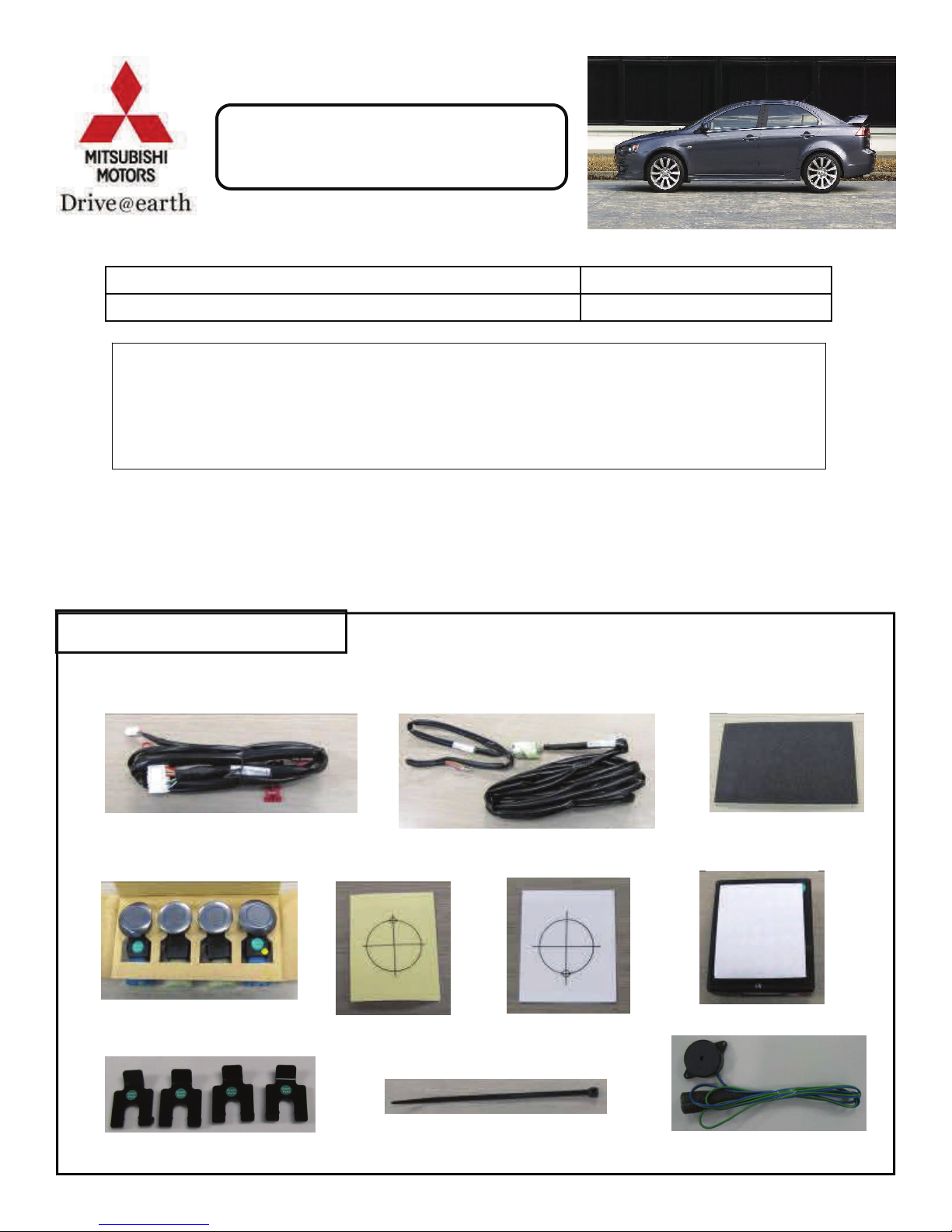
BILL OF MATERIALS:
#1 Wire Harness: 1 #2 Wire Harness: 1 #3 Wire Harness: 1 #4. Foam Pad: 9
#6. Sensors: 4
#10. Sensor Clips: 4
#7. 26mm Paster: 2
#11. Tie Wraps: 16
#8. 24mm Paster: 2
#5. Module: 1
#9. Buzzer: 1
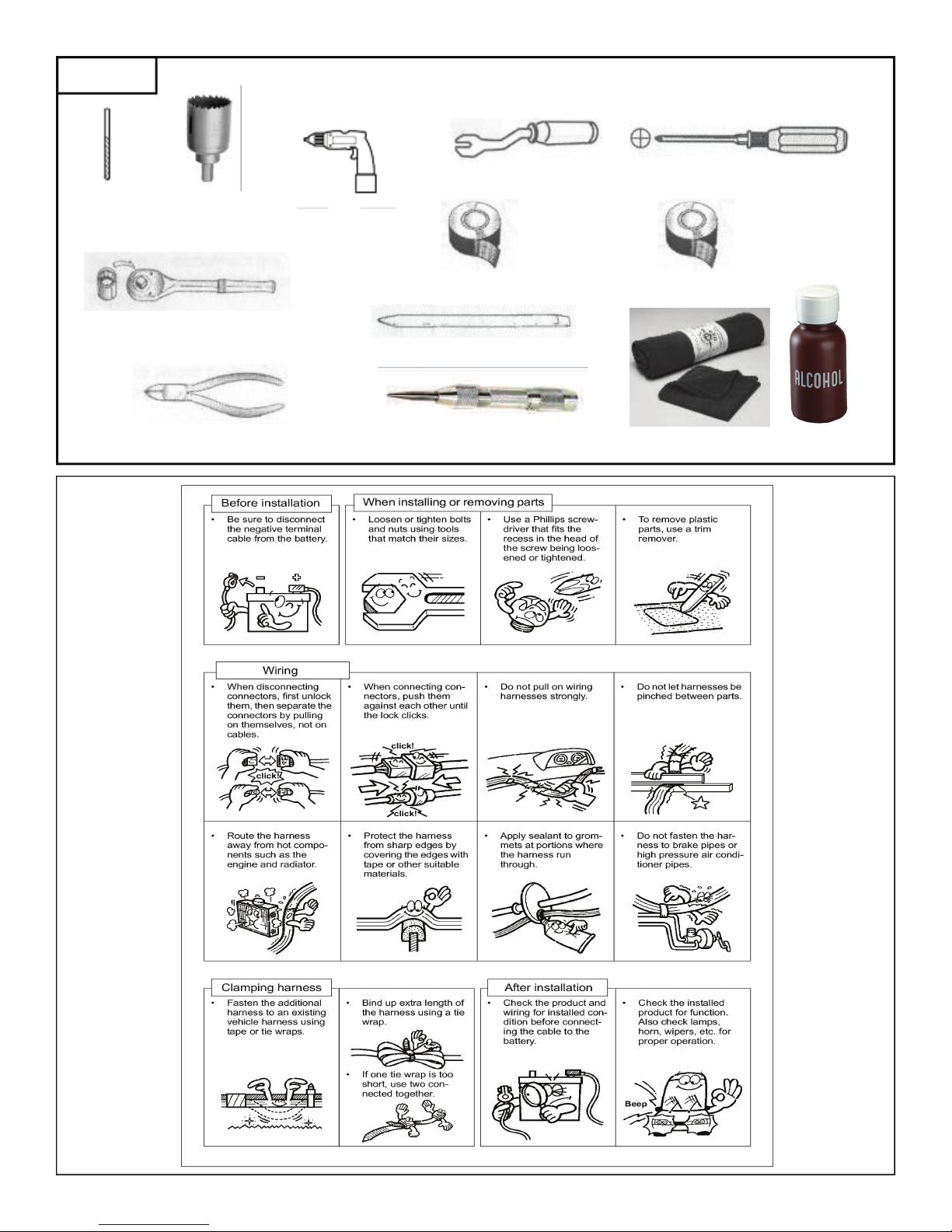
TOOLS
3mm bit
24mm
26mm
Hole saws
10mm socket wrench
Wire cutters
Drill
Masking tape
Trim stick
Center punch
Trim clip remover
Phillips screwdriver
Electrical tape
Rags
2
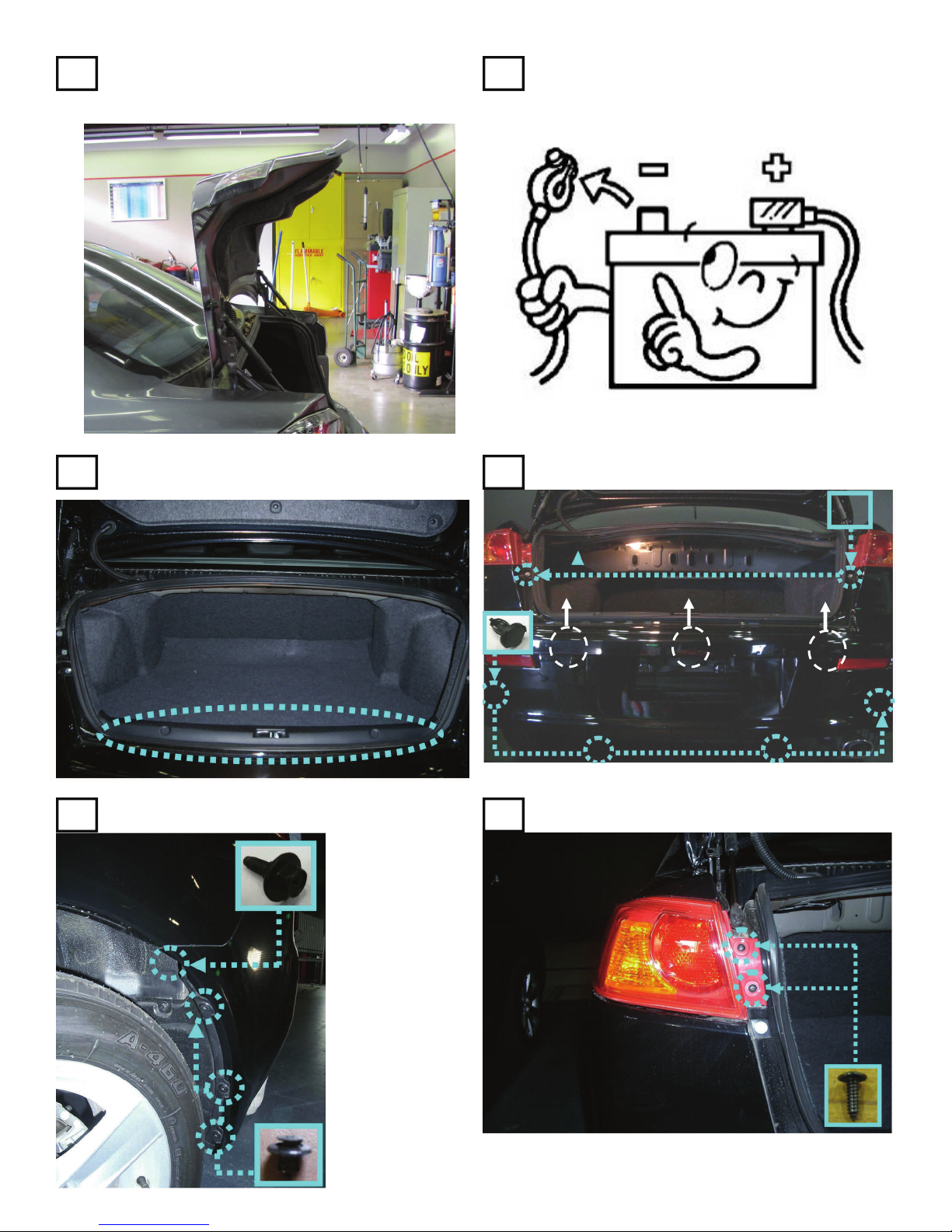
Open the trunk first. Use painters’ tape to pro-
1 2
tect the rear quarter sheet metal along side the
rear bumper fascia.
BEFORE INSTALLATION:
Disconnect NEGATIVE terminal
Dismantle the rear trim panel & remove trunk
3
floorboard.
Confirm painters tape along the sheet metal edge to
5
the bumper fascia
to protect from
scratching.
Dismantle rear side
bumper (left same
as right) and take
down the bumper.
Put it on a padded
bench to protect
the paint.
Dismantle the rear bumper clips.
4
Dismantle the left rear lamp assembly.
6
3
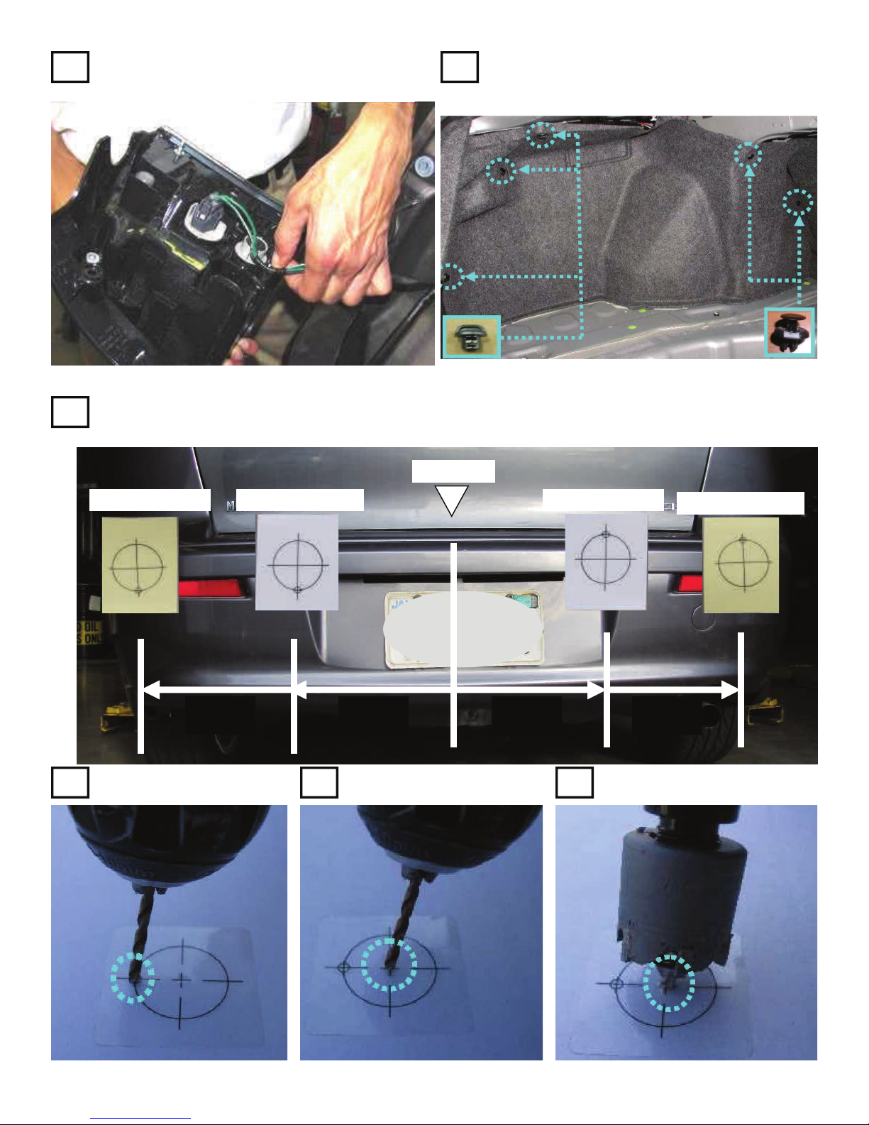
Remove lights from lamp assembly to leave wire
7 8
harness in place.
Using the trunk latch for center, measure and mark locations for the pasters. Center them vertically on the flat
9
facing area. Put the pasters on the rear bumper in the locations shown. Note the locating point direction
and hole sizes. Remove the fascia, secure on a padded bench and drill holes in Steps 10—12.
Trunk latch
Dismantle the left trunk trim panel and remove.
Save the fasteners.
#8. 24mm Paster #8. 24mm Paster #7. 26mm Paster
#7. 26mm Paster
35 cm 30 cm 30 cm 35 cm
Drill 3 mm locator holes Drill 3 mm center pilot holes Drill 24 mm and 26 mm holes.
10 11 12
4

Install Sensors #6 to the bumper as shown (BLUE outboard and GREEN in center locations). Note their orienta-
13
14
tion. Secure Sensors with Clips #10. Disconnect Wire Harness #2 from #3.
Layout Wire Harness #3
as shown by dotted lines.
Use alcohol to clean areas to adhere Foam Pads #4. Cut 2 Foam Pads #4 in half and secure Wire Harness #3
as shown by the four small arrows. Bundle with tie wrap #11 excess Wire Harness at large arrow and use full
size Foam Pad #4 to secure it.
5

15
16
Tape pins of Wire Harness #2 together and deploy through the left tail lamp grommet. Leave about 50 cm of
From Wire Harness #1, remove the connector housing, open it and prepare to install Wire Harness #2 pins into it.
Wire Harness #2 outside and secure with one Foam Pad #4 as shown by
the arrow. Securely tape all wires to the grommet with electrical tape.
17
3 4 5 6
2
1
LINE COLOR
1- None
2 -White/Black line
3 - Orange / Black Llne
4 - Blue / White line
5 - Red / White line
6 - Yellow / Green Line
6

Fully insert pins to the housing,
18
push locking tab in and connect
Wire Harnesses #1 and #2.
Clean areas with alcohol and install Module #5 to the left rear inner fender sheet metal. Connect Wire Harness #1
20
to Module #5. Attach the wire clip on the red wire in Wire Harness #1 to the thick white wire in the vehicle har-
ness. Cut the terminal off the black wire in Wire Harness #1 and use the wire clip to attach it to the black wire in
the vehicle harness. Wrap the red and black wires with electrical tape where they cross the wheel well sheet
metal and add Foam Pads #4 as shown to secure and protect the wires. CAUTION: Do not trap the trunk re-
lease or fuel door release cables with the foam pads. Peel the liner from the Buzzer #9 and install as shown.
19
Wire Harness #1
Wire Harness #2
Wire Harness #2
Buzzer #9
Half Foam Pads #4
CAUTION ! Connect to the thick
white wire!
Module #5
Wire Harness #1
Wire Harness #1. Bundle
excess harness here.
Use red clip attached to Wire Harness #1 to connect
black wire to black vehicle harness ground wire. Be sure
to hear the “click” when fully closed.
Whole Foam Pads #4
7

21
Before re-assembling the car, hold the rear bumper fascia up to the car, plug in the Rear Park Sensor, start
the car, put it in reverse and confirm the system sounds off with someone within 3 feet of the fascia.
Then turn the car off and re-assemble working the following steps in reverse from disassembly.
8
7 6 5 4
3
2
1
BE SURE TO GIVE THE OWNER MANUAL TO THE CUSTOMER
8

9

10

Product specification
Items Specification
Items Specification
Rated V
Rated Voltage DC 12.0V
Operation Voltage DC 9.6V~ 16V
Operation Voltage DC 9.6V~ 16V
Operation Temp -20Ԩ ~ 70Ԩ
Operation Temp -20Ԩ ~ 70Ԩ
Storage Temp -30Ԩ ~ 80Ԩ
Storage Temp -30Ԩ ~ 80Ԩ
oltage DC 12.0V
11
 Loading...