

Mitsubishi MXZ-4C36NAHZ-U1, MXZ-8C48NAHZ-U1, MXZ-5C42NAHZ-U1, MXZ-8C48NAHZ, MXZ-8C48NA Technical & Service Manual
...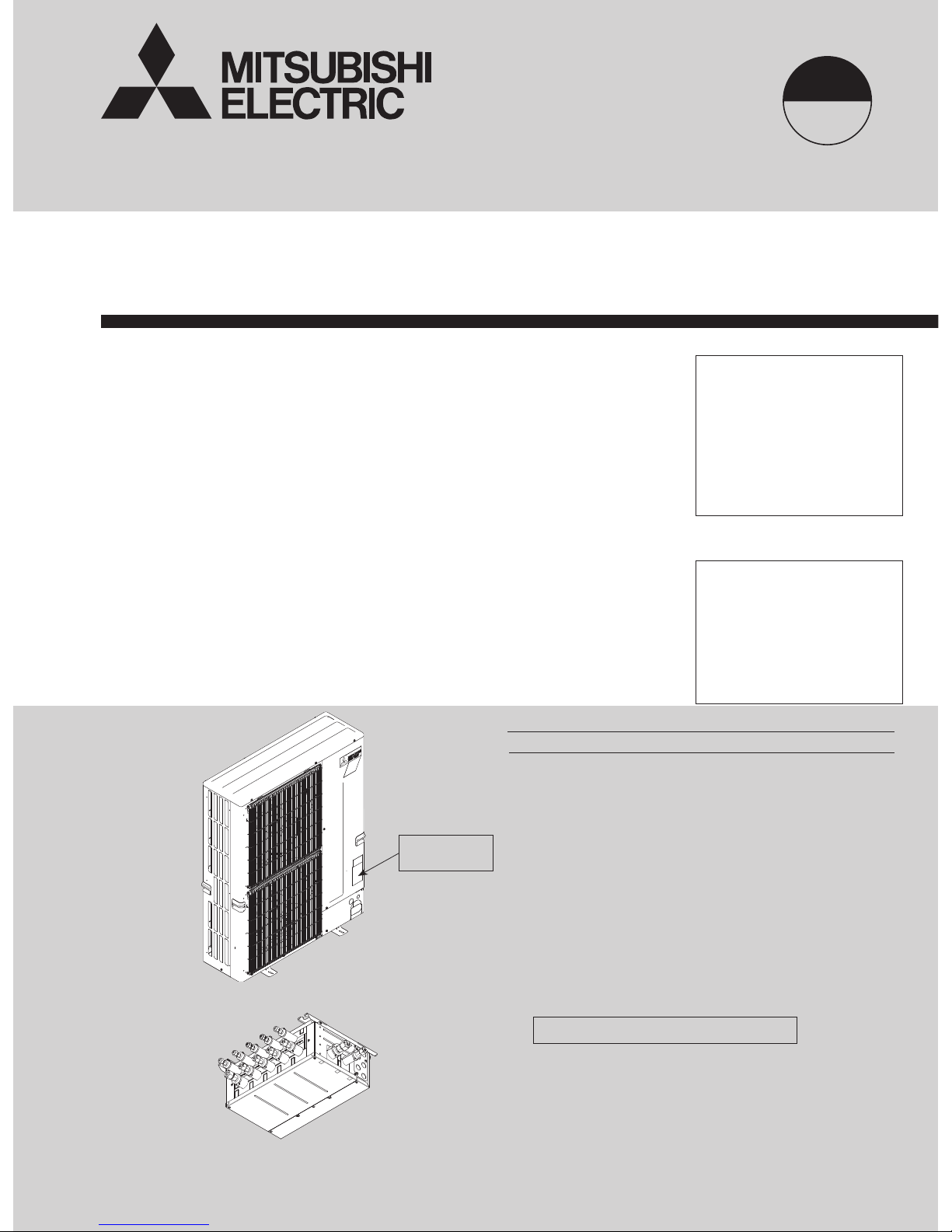
TECHNICAL & SERVICE MANUAL
CONTENTS
TECHNICAL CHANGES
.........................................
2
1. SAFETY PRECAUTION
....................................
3
2. OVERVIEW OF UNITS
......................................
6
3. SPECIFICATIONS
............................................
10
4. DATA
................................................................
14
5. OUTLINES AND DIMENSIONS
......................
36
6. WIRING DIAGRAM
.........................................
40
7.
NECESSARY CONDITIONS FOR SYSTEM CONSTRUCTION
....
47
8. TROUBLESHOOTING
....................................
52
9.
PRECAUTIONS AGAINST REFRIGERANT LEAKAGE
....
140
10. DISASSEMBLY PROCEDURE
......................
141
No. OCH573
REVISED EDITION-C
MXZ-4C36NAHZ MXZ-4C36NAHZ-U1
MXZ-5C42NAHZ MXZ-5C42NAHZ-U1
MXZ-8C48NAHZ MXZ-8C48NAHZ-U1
MXZ-8C48NA MXZ-8C48NA-U1
MXZ-8C60NA-U1
PAC-MKA50BC
PAC-MKA30BC
PAC-MKA51BC
PAC-MKA31BC
HFC
utilized
R410A
October 2016
Notes:
• This service manual
describes technical data of
outdoor unit and branch box.
As for indoor units, refer to
its service manual.
• RoHS compliant products
have <G> mark on the spec
name plate.
[Model Name]
<Outdoor unit>
MXZ-4C36NAHZ
MXZ-5C42NAHZ
MXZ-8C48NAHZ
MXZ-8C48NA
MXZ-8C60NA
<Branch box>
PAC-MKA50BC
PAC-MKA30BC
PAC-MKA51BC
PAC-MKA31BC
PARTS CATALOG (OCB573)
[Service Ref.]
OUTDOOR UNIT: MXZ-4C36NAHZ
BRANCH BOX: PAC-MKA51BC
Model name
indication
SPLIT-TYPE, HEAT PUMP AIR CONDITIONERS
Revision:
• Added PAC-MKA51BC,
PAC-MKA31BC,
MXZ-4C36NAHZ-U1,
MXZ-5C42NAHZ-U1,
MXZ-8C48NAHZ-U1,
MXZ-8C48NA-U1, and
MXZ-8C60NA-U1 in REVISED
EDITION-C.
• Some descriptions have been
modified.
OCH573 REVISED EDITION-B
is void.

2
TECHNICAL CHANGES
MXZ-4C36NAHZ MXZ-4C36NAHZ-U1
MXZ-5C42NAHZ MXZ-5C42NAHZ-U1
MXZ-8C48NAHZ MXZ-8C48NAHZ-U1
MXZ-8C48NA MXZ-8C48NA-U1
Service ref. have been changed as follows.
• The shape of piping around a stop valve (T7W E04 410) has been changed.
• The shape of valve bed has been changed.
OCH573C
3
Cautions for units utilizing refrigerant R410A
1-1. ALWAYS OBSERVE FOR SAFETY
Use new refrigerant pipes.
Charge refrigerant from liquid phase of gas
cylinder.
If the refrigerant is charged from gas phase, composition
change may occur in refrigerant and the efficiency will be
lowered.
Do not use refrigerant other than R410A.
If other refrigerant (R22, etc.) is used, chlorine in refrigerant can cause deterioration of refrigerant oil, etc.
Use a vacuum pump with a reverse flow check
valve.
Vacuum pump oil may flow back into refrigerant cycle and
that can cause deterioration of refrigerant oil, etc.
Use the following tools specifically designed for
use with R410A refrigerant.
The following tools are necessary to use R410A refrigerant.
Handle tools with care.
If dirt, dust or moisture enters into refrigerant cycle, that can
cause deterioration of refrigerant oil or malfunction of compressor.
Do not use a charging cylinder.
If a charging cylinder is used, the composition of refrigerant will change and the efficiency will be lowered.
Flare tool
Electronic refrigerant
charging scale
Vacuum pump adaptor
Size adjustment gauge
Gauge manifold
Torque wrench
Gas leak detector
Charge hose
Tools for R410A
Contamination inside refrigerant piping can cause deterioration of refrigerant oil, etc.
If large amount of mineral oil enters, that can cause deterioration of refrigerant oil, etc.
Make sure that the inside and outside of refrigerant piping is clean and it has no contaminants
such as sulfur, oxides, dirt, shaving particles, etc,
which are hazard to refrigerant cycle.
In addition, use pipes with specified thickness.
The refrigerant oil applied to flare and flange
connections must be ester oil, ether oil or
alkylbenzene oil in a small amount.
Ventilate the room if refrigerant leaks during
operation. If refrigerant comes into contact with
a flame, poisonous gases will be released.
Never use any refrigerant other than that specified.
Doing so may cause a burst, an explosion, or fire when the
unit is being used, serviced, or disposed of.
Correct refrigerant is specified in the manuals and on the
spec labels provided with our products.
We will not be held responsible for mechanical failure,
system malfunction, unit breakdown or accidents caused
by failure to follow the instructions.
Use the specified refrigerant only.
Store the piping indoors, and both ends of the
piping sealed until just before brazing.
(Leave elbow joints, etc. in their packaging.)
If dirt, dust or moisture enters into refrigerant cycle, that can
cause deterioration of refrigerant oil or malfunction of compressor.
1-2. CAUTIONS RELATED TO NEW REFRIGERANT
Before obtaining access to terminal, all supply
circuit must be disconnected.
1 SAFETY PRECAUTION
OCH573C
4
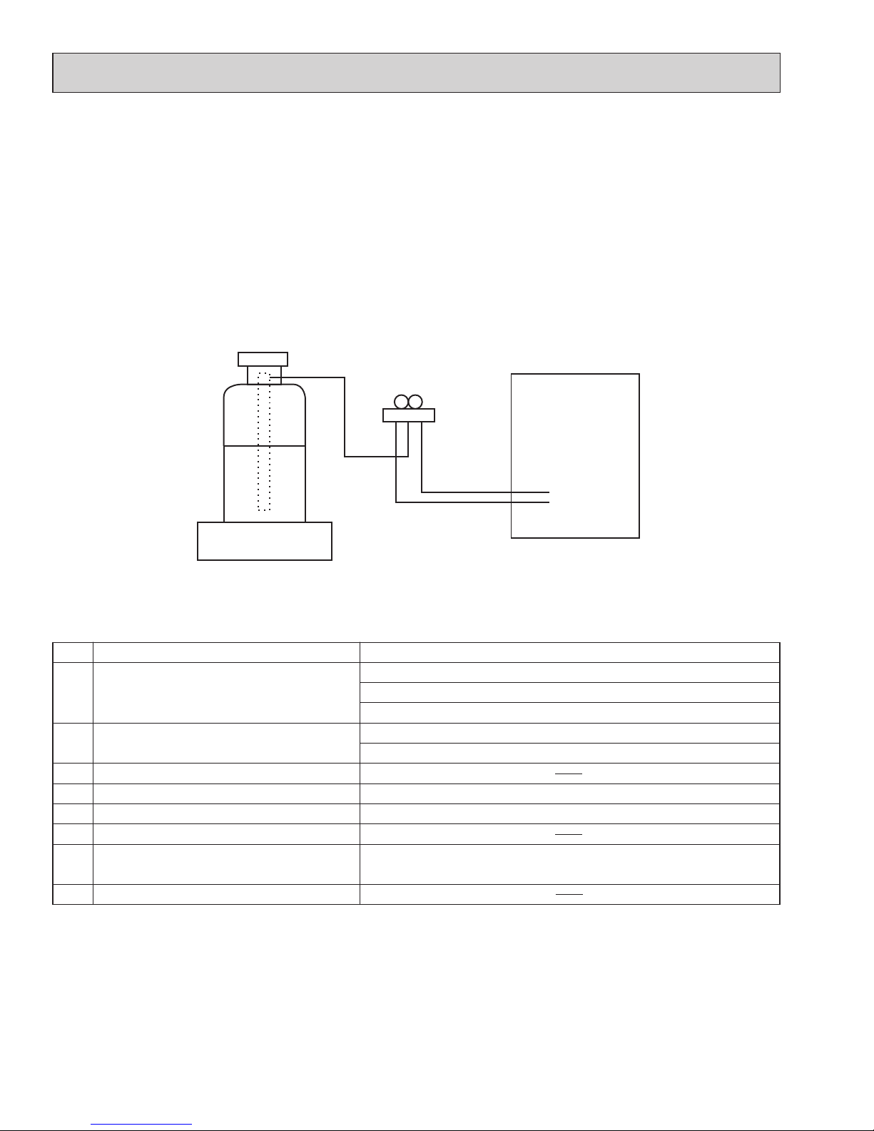
Unit
Electronic weighing scale
[3] Service tools
(1) Use the below service tools as exclusive tools for R410A refrigerant.
No. Tool name Specifications
1 Gauge manifold ·Only for R410A
·Use the existing fitting
specifications
. (UNF1/2)
·
Use high-tension side pressure of 768.7 PSIG [5.3 MPaG] or over.
2 Charge hose ·Only for R410A
·Use pressure performance of 738.2 PSIG [5.09MPaG] or over.
3 Electronic scale
4 Gas leak detector ·Use the detector for R134a, R407C or R410A.
5 Adaptor for reverse flow check ·Attach on vacuum pump.
6 Refrigerant charge base
7 Refrigerant cylinder ·Only for R410A ·Top of cylinder (Pink)
·Cylinder with syphon
8 Refrigerant recovery equipment
[2] Additional refrigerant charge
When charging directly from cylinder
(1) Check that cylinder for R410A on the market is a syphon type.
(2) Charging should be performed with the cylinder of syphon stood vertically. (Refrigerant is charged from liquid phase.)
[1] Cautions for service
(1) Perform service after recovering the refrigerant left in unit completely.
(2) Do not release refrigerant in the air.
(3) After completing service, charge the cycle with specified amount of refrigerant.
(4) If moisture or foreign matter might have entered the refrigerant piping during service, ensure to remove them.
OCH573C
5
1-3. Cautions for refrigerant piping work
New refrigerant R410A is adopted for replacement inverter series. Although the refrigerant piping work for R410A is
same as for R22, exclusive tools are necessary so as not to mix with different kind of refrigerant. Furthermore as the
working pressure of R410A is 1.6 times higher than that of R22, their sizes of flared sections and flare nuts are different.
1 Thickness of pipes
Because the working pressure of R410A is higher compared to R22, be sure to use refrigerant piping with thickness
shown below. (Never use pipes of 7/256 in [0.7 mm] or below.)
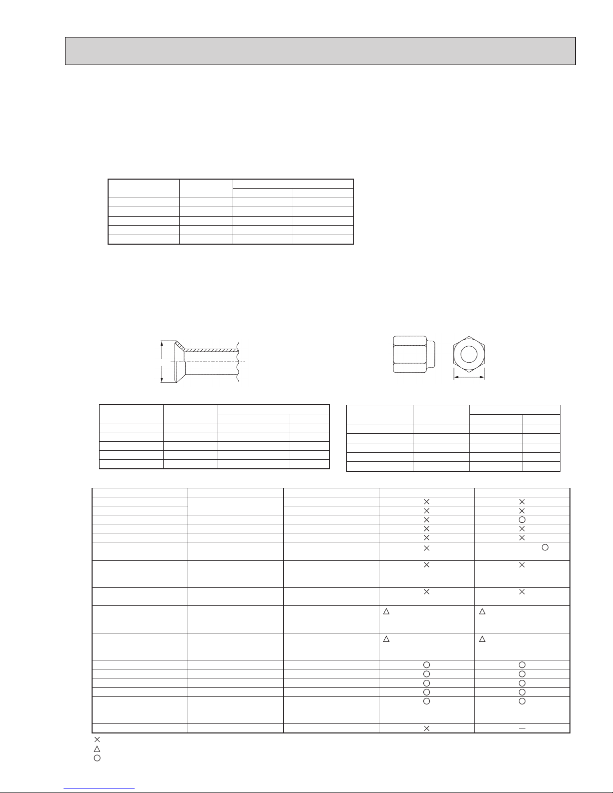
2 Dimensions of flare cutting and flare nut
The component molecules in HFC refrigerant are smaller compared to conventional refrigerants. In addition to that,
R410A is a refrigerant, which has higher risk of leakage because its working pressure is higher than that of other
refrigerants. Therefore, to enhance airtightness and strength, flare cutting dimension of copper pipe for R410A has
been specified separately from the dimensions for other refrigerants as shown below. The dimension B of flare nut for
R410A also has partly been changed to increase strength as shown below. Set copper pipe correctly referring to copper pipe flaring dimensions for R410A below. For 1/2 and 5/8 inch pipes, the dimension B changes.
Use torque wrench corresponding to each dimension.
3 Tools for R410A (The following table shows whether conventional tools can be used or not.)
1/4
3/8
1/2
5/8
3/4
6.35
9.52
12.70
15.88
19.05
1/32 [0.8]
1/32 [0.8]
1/32 [0.8]
5/128 [1.0]
—
1/32 [0.8]
1/32 [0.8]
1/32 [0.8]
5/128 [1.0]
5/128 [1.0]
Nominal
dimensions
(in)
Diagram below: Piping diameter and thickness
Outside
diameter
(mm)
Thickness
: in [mm]
R410A R22
1/4
3/8
1/2
5/8
3/4
6.35
9.52
12.70
15.88
19.05
11/32-23/64 [ 9.1]
1/2-33/64 [13.2]
41/64-21/32 [16.6]
49/64-25/32 [19.7]
—
9.0
13.0
16.2
19.4
23.3
Nominal
dimensions (in)
Flare cutting dimensions
Outside
diameter (mm)
Dimension A
( )
+0
-0.4
Unit : in [mm]
R410A R22
1/4
3/8
1/2
5/8
3/4
6.35
9.52
12.70
15.88
19.05
43/64 [17.0]
7/8 [22.0]
1-3/64 [26.0]
1-9/64 [29.0]
17.0
22.0
24.0
27.0
36.0
Nominal
dimensions (in)
Flare nut dimensions
Outside
diameter (mm)
Dimension B
Unit: in [mm]
R410A R22
—
Gauge manifold
Charge hose
Gas leak detector
Refrigerant recovery equipment
Refrigerant cylinder
Applied oil
Safety charger
Charge valve
Vacuum pump
Flare tool
Bender
Pipe cutter
Welder and nitrogen gas cylinder
Refrigerant charging scale
Vacuum gauge or thermistor vacuum gauge and
vacuum valve
Charging cylinder
Air purge, refrigerant charge
and operation check
Gas leak check
Refrigerant recovery
Refrigerant charge
Apply to flared section
Prevent compressor malfunction
when charging refrigerant by
spraying liquid refrigerant
Prevent gas from blowing out
when detaching charge hose
Vacuum drying and air
purge
Flaring work of piping
Bend the pipes
Cut the pipes
Weld the pipes
Refrigerant charge
Check the degree of vacuum. (Vacuum
valve prevents back flow of oil and refrigerant to thermistor vacuum gauge)
Refrigerant charge
Tool exclusive for R410A
Tool exclusive for R410A
Tool for HFC refrigerant
Tool exclusive for R410A
Tool exclusive for R410A
Ester oil, ether oil and
alkylbenzene oil (minimum amount)
Tool exclusive for R410A
Tool exclusive for R410A
Tools for other refrigerants can
be used if equipped with adopter for reverse flow check
Tools for other refrigerants
can be used by adjusting
flaring dimension
Tools for other refrigerants can be used
Tools for other refrigerants can be used
Tools for other refrigerants can be used
Tools for other refrigerants can be used
Tools for other refrigerants
can be used
Tool exclusive for R410A
Tools and materials Use R410A tools Can R22 tools be used?
(Usable if equipped
with adopter for rever se flow)
(Usable by adjusting
flaring dimension)
Can R407C tools be used?
Ester oil, ether oil:
Alkylbenzene oil: minimum amount
(Usable if equipped
with adopter for rever se flow)
(Usable by adjusting
flaring dimension)
: Prepare a new tool. (Use the new tool as the tool exclusive for R410A.)
: Tools for other refrigerants can be used under certain conditions.
: Tools for other refrigerants can be used.
Dimension A
Dimension B
OCH573C

6
2 OVERVIEW OF UNITS
2-1. CONSTRUCTION OF SYSTEM
Outdoor unit
MXZ-4C36NAHZ(-U1) MXZ-5C42NAHZ(-U1)
MXZ-8C48NAHZ(-U1)
MXZ-8C48NA(-U1)
MXZ-8C60NA-U1
4HP 4.5HP 5HP 7HP
Rated capacity
(kBTU/h)
Cooling 36 42 48 60
Heating 45 48 54 66
Refrigerant R410A
Connectable
indoor unit
Capacity Type 06 to Type 36
Caution: The indoor unit which rated capacity exceeds
36 kBTU/ h (Type 36) can NOT be connected.
Number of units 2(*
1
) to 4 units 2(*1) to 5 units 2(*1) to 8 units 2(*1) to 8 units
Total system wide capacity 33 to 130% of outdoor
unit capacity
(12 to 46.8 kBTU/h)
29 to 130% of outdoor
unit capacity
(12 to 54.6 kBTU/h)
25 to 130% of outdoor
unit capacity
(12 to 62.4 kBTU/h)
20 to 130% of outdoor
unit capacity
(12 to 78 kBTU/h)
Connectable
branch box
Number of units
1 or 2 units
Connectable indoor unit lineups (Heat pump inverter type)
Model type Model name Capacity class [kBTU/h]
06 09 12 15 18 24 30 36
Wall
mounted
Deluxe
MSZ-FE09/12/18NA
MSZ-FH06/09/12/15NA, 18NA2
Designer
MSZ-EF09/12/15/18NA(W/B/S)
Standard
MSZ-GE06/09/12/15/18/24NA
MSZ-GL06/09/12/15/18/24NA
Ceiling
concealed
Low static pressure*
3
SEZ-KD09/12/15/18NA
Middle static pressure*
3
PEAD-A24/30/36AA5
4-way ceiling
cassette
2 by 2 type
SLZ-KA09/12/15NA
Standard
PLA-A12/18/24/30/36BA6
PLA-A12/18/24/30/36EA7*
4
Floor standing
MFZ-KA09/12/18NA
MFZ-KJ09/12/15/18NA
Multi-position*
2
MVZ-A12/18/24/30/36AA4
● Models other than MXZ-8C60NA
Number of connecting
multi-position unit
Constraints
2
Any indoor units other than multi-position models
are not connectable.
1
None
(Only the ordinal constraints apply.)
Option Optional accessories for indoor units and outdoor units are available.
2- branch pipe (joint): Optional parts
In case of using 1- branch box No need
In case of using 2- branch boxes
Model name Connection method
MSDD-50AR-E are
MSDD-50BR-E brazing
Branch box PAC-MKA50BC PAC-MKA51BC PAC-MKA30BC PAC-MKA31BC
Number of branches
(Indoor unit that can be connected)
5 branches
(MAX. 5 units)
3 branches
(MAX. 3 units)
Note: A maximum of 2 branch boxes can be connected to 1 outdoor unit.
● MXZ-8C60NA
(For each connected branch box)
Number of connecting
multi-position unit
Constraints
2
Any indoor units other than multi-position
models are not connectable.
1
·
The total system wide capacity should be 100%
or below including the MVZ-series unit.
· Only 1 SEZ or 1 PEAD can be included in the
connection.
*3 For MXZ-8C60NA; When connecting the SEZ and PEAD-series units, the total system wide capacity per 1 branch box should be 100% or
below including the SEZ and PEAD-series units. (Only if connecting to PAC-MKA50/51BC)
*4 When the system includes even 1 unit of PLA-A·EA7, the number of the maximum connectable indoor units is decreased as follows:
3 for MXZ-4C36NAHZ-U1, 4 for MXZ-5C42NAHZ-U1, and 6 for MXZ-8C48NA(HZ)-U1 and MXZ-8C60NA-U1
*
1
1 for MVZ model.
Single unit connection is possible with MVZ-series unit.
*2 When connecting a multi-position unit(s), set additional constraints as follows. For connections other than those specied below, consult your dealer.
Select a model according to the
connection method.
OCH573C
7
Indoor unit (Ceiling concealed type)
Indoor unit
(Wall mounted type)
Outdoor unit
Branch box
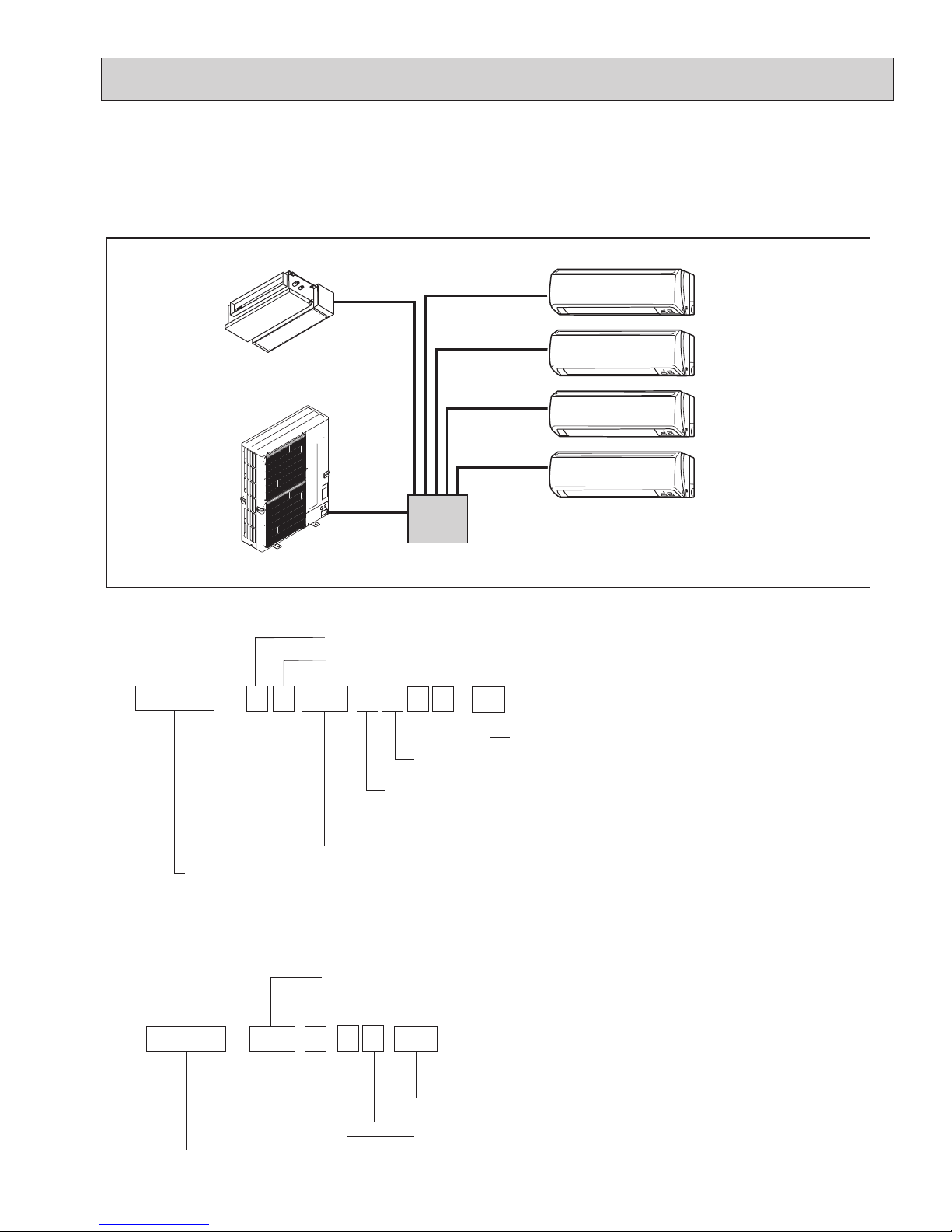
2-2. SYSTEM OUTLINE
The additional connection of the branch box together with employment of the compact trunk-looking outdoor unit can successfully realize a long distance piping for large houses. Equipped with a microcomputer, the branch box can translate the
transmission signal of indoor units to achieve the optimum control.
2-2-1. System example
2-2-2. Method for identifying
■ Outdoor unit
Development No. : A, B, ···,etc.
Power supply
N: Single phase 208/230 V 60Hz
Multi type heat pump
inverter outdoor unit
Indicates equivalent to rated cooling capacity.
(kBTU/h)
Number of connectable indoor units (MAX.)
Control and refrigerant
A : New A control and R410A
Model type
M X Z
-
4 88 C N A
P A
C
-
MK
A
5 1 B C
H Z
-
U1
Sub-number
(Indispensable)
Optional parts
Model type
Branch box (Controller)
Number of branches
5 : 5 branches
3 : 3 branches
Marketable area
A: America, Canada
■ Branch box
OCH573C
8
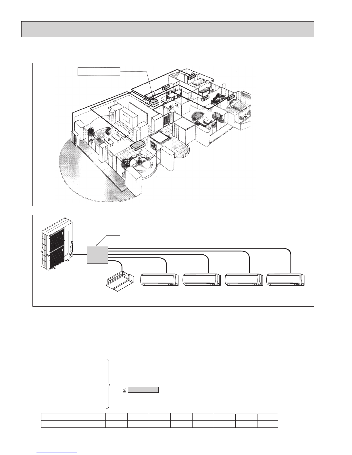
2-3. TYPICAL COMBINATION EXAMPLE
Branch box is located INSIDE of condominium
Branch box
(Inside)
Installing branch box indoors
Only 1 piping is required between the outdoor and
indoor offering a fine external view.
Branch box (5-branches type)
Outdoor unit
SEZ-18 MSZ-12 MSZ-12 MSZ-09 MSZ-09
Living
Dining Bedroom (1) Bedroom (2)
Master
bedroom
Indoor unit type (capacity class)
Rated capacity (cooling) (kBTU/h)066
09
9
12
12
15
15
24
24
18
18
30
30
36
36
■ System example of 5 indoor units
■ Verification (In case of MXZ-8C48NAHZ)
The rated capacity should be determined by observing the table below. The unit’s quantities are limited to 1(*) to 8
units. For the next step, make sure that the selected total rated capacity is in a range of 12 to 62.4 kBTU/h.
The total indoor unit capacity should be within the outdoor units. (= 48.0 kBTU/h is preferred).
Combination of excessive indoor units and an outdoor unit may reduce the capacity of each indoor unit.
The rated indoor capacity is as the table below.
*Single unit connection is possible only with MVZ model. Connect 2 or more units for models other than MVZ.
Example:
Total rated capacity
60 62.4 kBTU/h
MSZ-09 = 9
+
+
+
+
SEZ-18 = 18
MSZ-12 = 12
MSZ-12 = 12
MSZ-09 = 9
OCH573C
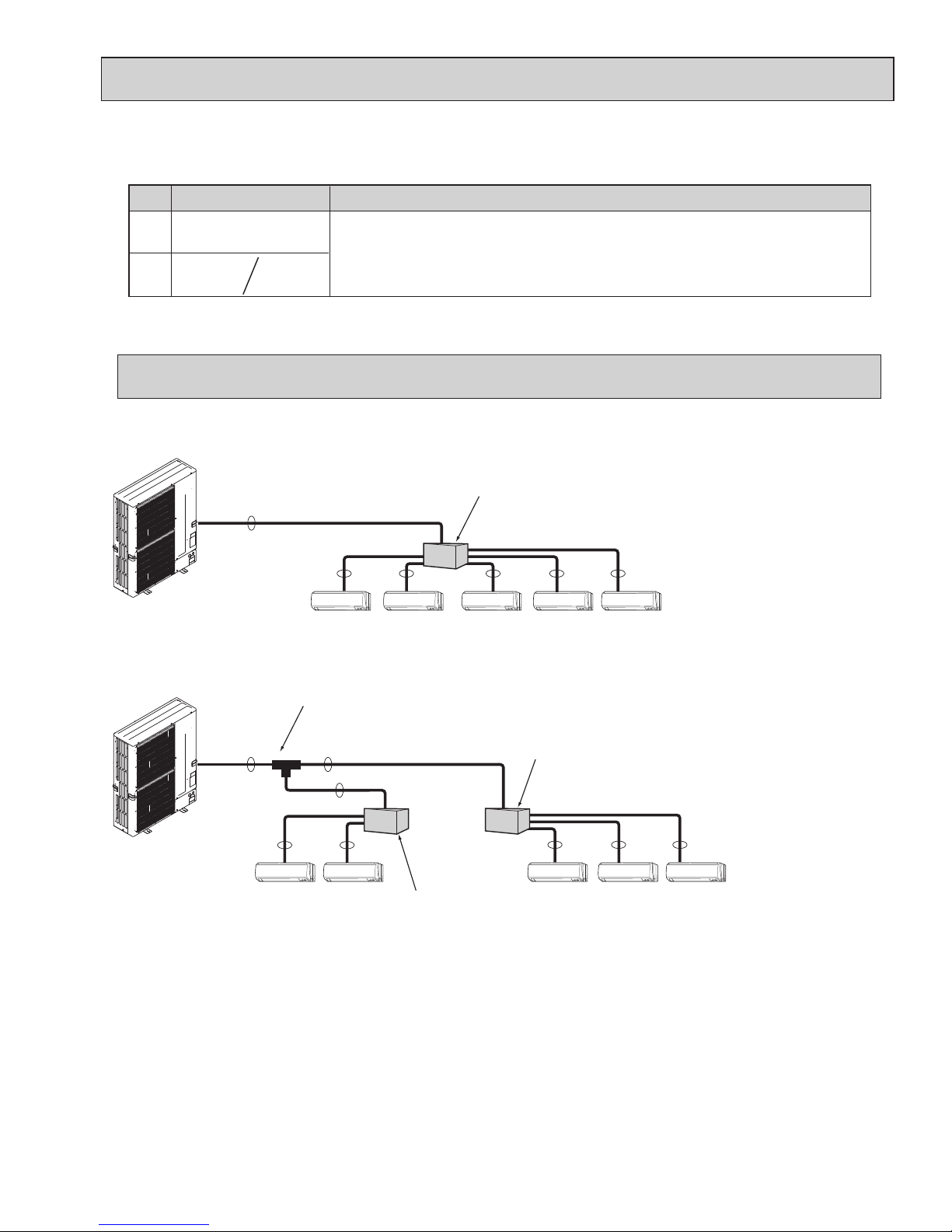
2-4. SIMPLIFIED PIPING SYSTEM
Piping connection size
Liquid
Gas
{3/8 inch
[9.52 mm]
{5/8 inch
[15.88 mm]
The piping connection size differs according to the type and capacity of indoor units.
Match the piping connection size of branch box with indoor unit.
If the piping connection size of branch box does not match the piping connection size of
indoor unit, use optional different-diameter (deformed) joints to the branch box side.
(Connect deformed joint directly to the branch box side.)
A B
{3/4 inch*
[19.05 mm]
* MXZ-8C60NA only
Flare connection employed. (No brazing!)
A
B B B B B
Branch box
■ In case of using 1-branch box
Flare connection employed (No brazing)
A
A
A
B B
B B B
2 branches pipe (joint)
: optional parts
Branch box #1
Branch box #2
■ In case of using 2-branch boxes
■ Installation procedure (2 branches pipe (joint))
Refer to the installation manuals of MSDD-50AR-E and MSDD-50BR-E.
9
OCH573C
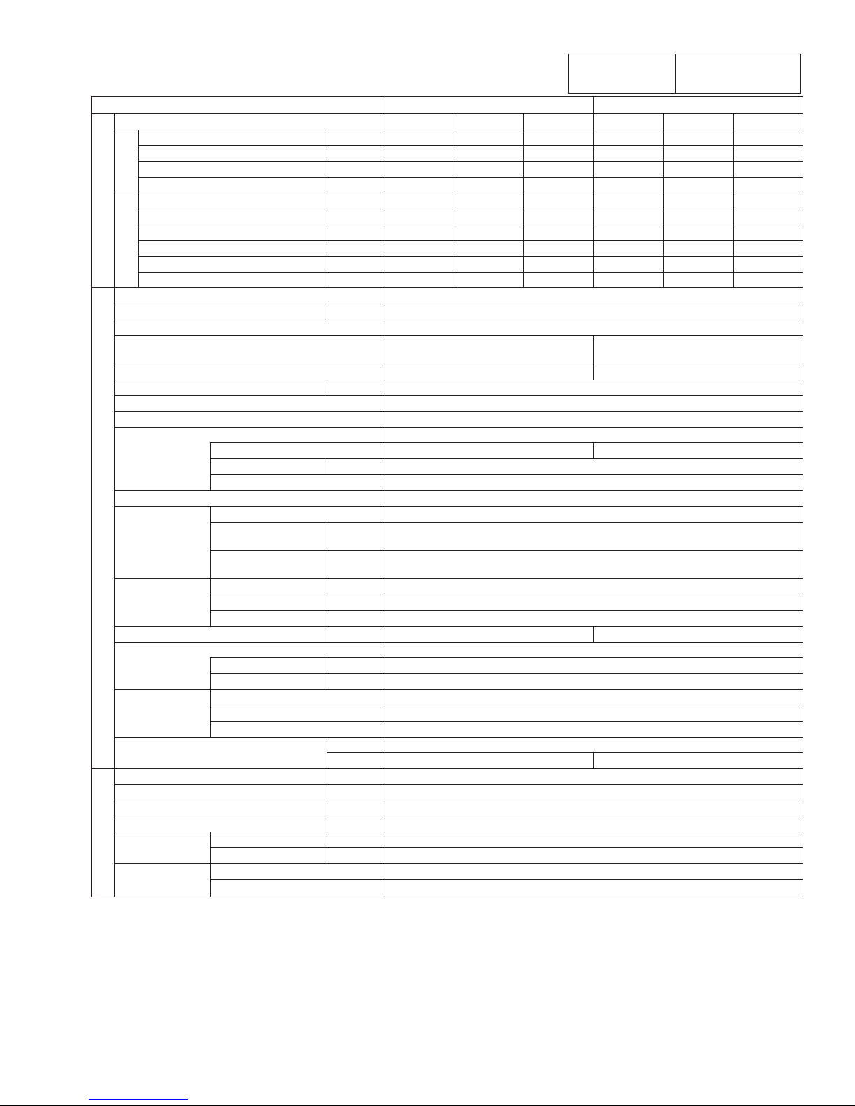
3 SPECIFICATIONS
3-1.
OUTDOOR UNIT
:
MXZ-4C36/5C42/8C48NAHZ(-U1), MXZ-8C48NA(-U1), MXZ-8C60NA-U1
Conversion formula:
kcal/h = kW o 860
BTU/h = kW o 3412
CFM = m
3
/min o 35.31
10
Service Ref. MXZ-4C36NAHZ(-U1) MXZ-5C42NAHZ(-U1)
Standard performance
Indoor type
Non-Ducted
Mix Ducted
Non-Ducted
Mix Ducted
Cooling
Capacity Rated*
1
BTU/h 36,000 36,000 36,000 42,000 42,000 42,000
Rated power consumption*
1
W 2,570 2,845 3,180 3,130 3,470 3,890
EER BTU/Wh 14.00 12.65 11.30 13.40 12.10 10.80
SEER BTU/Wh 19.1 17.5 15.8 19.0 17.0 15.0
Heating
Capacity Rated 47°F
*
1
BTU/h 45,000 45,000 45,000 48,000 48,000 48,000
Capacity Max. 17°F
*
2
BTU/h 45,000 45,000 45,000 48,000 48,000 48,000
Capacity Max. 5°F BTU/h 45,000 45,000 45,000 48,000 48,000 48,000
Rated power consumption 47°F
*
1
W 3,340 3,795 4,250 3,430 3,890 4,350
COP 47°F
*1 BTU/Wh 3.95 3.48 3.10 4.10 3.62 3.23
HSPF 4/
5
BTU/Wh 11.3/9.2 10.7/8.9 10.1/8.5 11.0/9.1 10.6/9.0 10.1/8.8
OUTDOOR UNIT
Connectable indoor units (Max.) 4 5
Max. Connectable Capacity BTU/h 46,000 54,000
Power supply 1 Phase 208/230 V, 60 Hz
Breaker Size/Max. fuse size 50 A/52 A
50 A/50 A (for the models with U1)
Min. circuit ampacity 42 A
Sound level (Cool/Heat) dB 49/ 53 50/ 54
External nish Munsell 3Y 7.8/ 1.1
Refrigerant control Linear Expansion Valve
Compressor Hermetic
Model ANB33FJSMT
Motor output kW 2.8 3.0
Starting method Inverter
Heat exchanger Plate n coil
Fan Fan (drive) × No. Propeller fan × 2
Fan motor output kW 0.06 + 0.06
0.074 + 0.074 (for the models with U1)
Airow m³/min
(CFM)
110 (3885)
Dimensions
(H × W × D)
W
in (mm)
41-11/32 (1050)
D
in (mm)
13+1 (330+25)
H
in (mm)
52-11/16 (1338)
Weight lb (kg) 276 (125)
Refrigerant R410A
Charge lb (kg) 10 lbs. 9 oz.(4.8)
Oil/Model oz (L) 73 (2.3)/Ethereal oil (FV50S)
Protection devices
High pressure protection HP switch
Compressor protection
Compressor thermo, Overcurrent detection
Fan motor protection Overheating/Voltage protection
Guaranteed operation range (cool) D.B 23 to 115°F [ D.B.−5 to 46°C ]
*
3
(heat) D.B. −13 to 70°F [D.B. −25 to 21°C ]
REFRIGERANT PIPING
Total Piping length (Max.) ft (m) 492 (150)
Farthest ft (m) 262 (80)
Max. Height difference ft (m) 164 (50)
*
4
Chargeless length ft (m) 0
Piping diameter Liquid
[inch (mm)
[3/8 (9.52)
Gas
[inch (mm)
[5/8 (15.88)
Connection
method
Indoor side Flared
Outdoor side Flared
*1
Rating conditions Cooling Indoor : D.B. 80°F/W.B. 67 °F [D.B.26.7°C/W.B. 19.4°C]
Outdoor : D.B. 95°F [D.B. 35.0°C]
Heating Indoor : D.B. 70°F [D.B. 21.1°C]
Outdoor : D.B. 47°F/W.B. 43°F [D.B. 8.3°C/W.B. 6.1°C]
*
2
Conditions Heating Indoor : D.B. 70°F [D.B. 21.1°C]
Outdoor : D.B. 17°F/W.B. 15°F [D.B. −8.3°C/W.B. −9.4°C]
*
3
D.B. 5 to 115°F [D.B. −15 to 46°C], when an optional Air Outlet Guide is installed.
*
4
131 ft [40 m], in case of installing outdoor unit lower than indoor unit.
Note: Refer to the indoor unit's service manual for the indoor units specications.
OCH573C
11
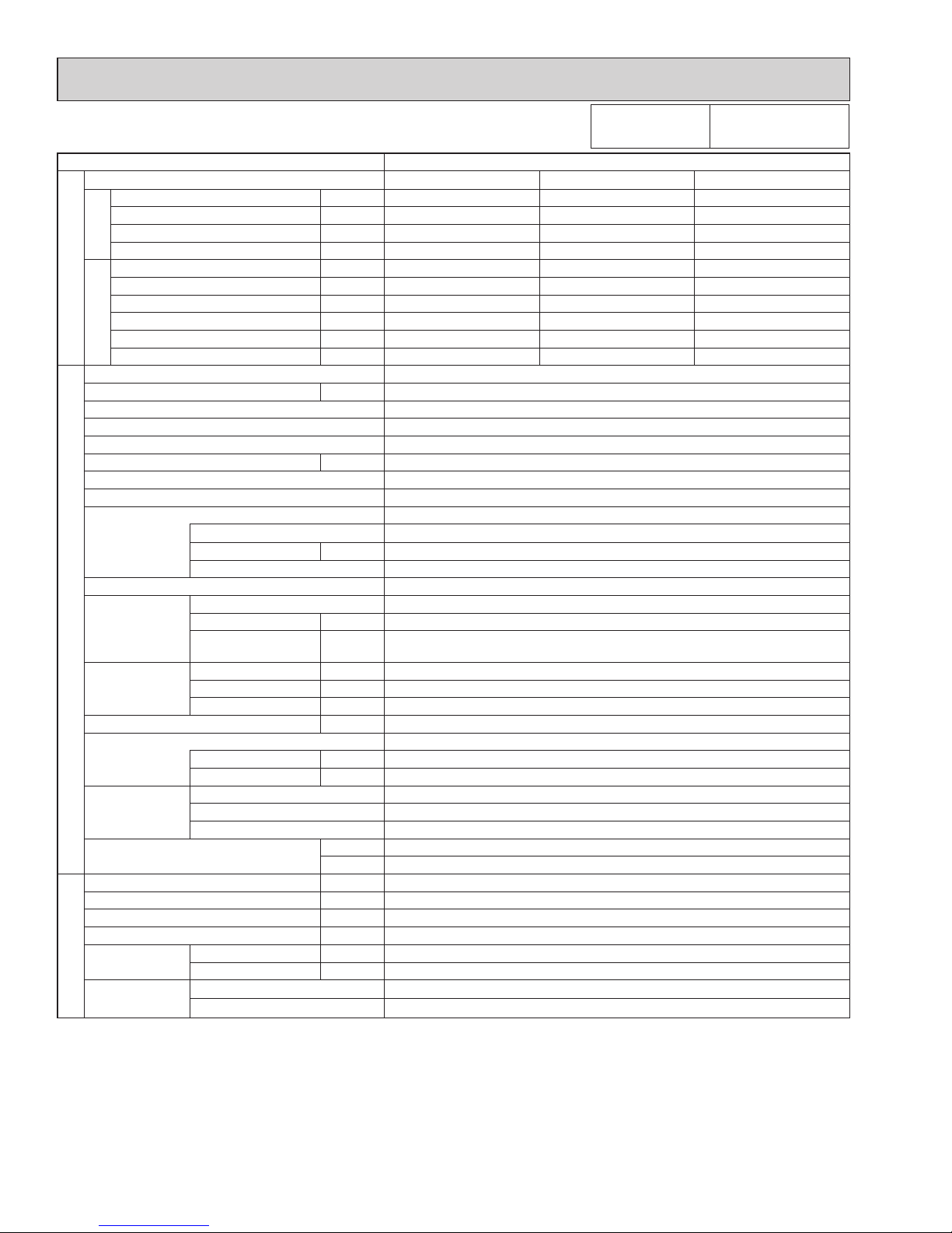
Service Ref. MXZ-8C48NAHZ(-U1) MXZ-8C48NA(-U1)
Standard performance
Indoor type
Non-Ducted
Mix Ducted
Non-Ducted
Mix Ducted
Cooling
Capacity Rated*
1
BTU/h 48,000 48,000 48,000 48,000 48,000 48,000
Rated power consumption*1
W 4,000 4,465 5,050 4,000 4,465 5,050
EER BTU/Wh 12.00 10.75 9.50 12.00 10.75 9.50
SEER BTU/Wh 18.9 16.8 14.7 18.9 16.8 14.7
Heating
Capacity Rated 47°F
*
1
BTU/h 54,000 54,000 54,000 54,000 54,000 54,000
Capacity 17°F
*
2
BTU/h 54,000 54,000 54,000 36,600 36,600 36,600
Capacity 5°F BTU/h 54,000 54,000 54,000 32,400 32,400 32,400
Rated power consumption 47°F*1
W 4,220 4,605 4,990 4,220 4,605 4,990
COP 47°F
*
1
BTU/Wh 3.75 3.44 3.17 3.75 3.44 3.17
HSPF 4/
5
BTU/Wh 11.0/9.2 10.5/9.2 10.0/9.2 11.4/8.7 10.8/8.6 10.1/8.4
OUTDOOR UNIT
Connectable indoor units (Max.) 8
Max. Connectable Capacity BTU/h 62,000
Power supply 1 Phase 208/230 V, 60 Hz
Breaker Size / Max. fuse size 50 A/ 52 A
50 A/50 A (for the models with U1)
40 A/52 A
40 A/50 A (for the models with U1)
Min. circuit ampacity 42 A 37 A
Sound level (Cool/Heat) dB 51/ 54
External nish Munsell 3Y 7.8 / 1.1
Refrigerant control Linear Expansion Valve
Compressor Hermetic
Model ANB33FJSMT ANB33FNHMT
Motor output kW 3.4
Starting method Inverter
Heat exchanger Plate n coil
Fan Fan (drive) × No. Propeller fan × 2
Fan motor output kW 0.06 + 0.06
0.074 + 0.074 (for the models with U1)
Airow m³/min
(CFM)
110 (3885)
Dimensions
(H × W × D)
W inch (mm) 41-11/32 (1050)
D inch (mm) 13+1 (330+25)
H inch (mm) 52-11/16 (1338)
Weight lb (kg) 276 (125) 269 (122)
Refrigerant R410A
Charge lb (kg) 10 lbs. 9 oz. (4.8 )
Oil / Model oz (L) 73 (2.3) / Ethereal oil (FV50S)
Protection
devices
High pressure protection HP switch
Compressor protection
Compressor thermo, Over current detection
Fan motor protection Overheating/Voltage protection
Guaranteed operation range (cool) D.B. 23 to 115°F [ D.B. −5 to 46°C]
*3
(heat) D.B. −13 to 70°F [D.B. −25 to 21°C] D.B. −4 to 70°F [D.B. −20 to 21°C]
REFRIGERANT PIPING
Total Piping length (Max.) ft (m) 492 (150)
Farthest ft (m) 262 (80)
Max. Height difference ft (m) 164 (50)
*4
Chargeless length ft (m) 0
Piping diameter Liquid
[inch (mm)
[3/8 (9.52)
Gas
[inch (mm)
[ 5/8 (15.88)
Connection
method
Indoor side Flared
Outdoor side Flared
*
1
Rating conditions Cooling Indoor : D.B. 80°F/W.B. 67°F [D.B. 26.7°C/W.B. 19.4°C]
Outdoor : D.B. 95°F [D.B. 35.0°C]
Heating Indoor : D.B. 70°F [D.B. 21.1°C]
Outdoor : D.B. 47°F/W.B. 43°F [D.B. 8.3°C/W.B. 6.1°C]
*
2
Conditions Heating Indoor : D.B. 70°F [D.B. 21.1°C]
Outdoor : D.B. 17°F/W.B. 15°F [D.B. −8.3°C/W.B. −9.4°C]
*
3
D.B. 5 to 115°F [D.B. −15 to 46°C], when an optional Air Outlet Guide is installed.
*
4
131 ft [40 m], in case of installing outdoor unit lower than indoor unit.
Note: Refer to the indoor unit's service manual for the indoor units specications.
Conversion formula:
kcal/h = kW o 860
BTU/h = kW o 3412
CFM = m
3
/min o 35.31
OCH573C
12
Service Ref. MXZ-8C60NA-U1
Standard performance
Indoor type
Non-Ducted
Mix Ducted
Cooling
Capacity Rated*
1
BTU/h 60,000 60,000 60,000
Rated power consumption*
1
W 4,800 5,525 6,250
EER BTU/Wh 12.50 11.05 9.60
SEER BTU/Wh 17.4 16.3 15.1
Heating
Capacity Rated 47°F
*
1
BTU/h 66,000 66,000 66,000
Capacity Max. 17°F
*
2
BTU/h 65,000 61,500 58,000
Capacity Max. 5°F BTU/h 57,000 49,500 42,000
Rated power consumption 47°F
*
1
W 4,870 4,810 4,750
COP 47°F
*1 BTU/Wh 3.40 3.40 3.40
HSPF 4/
5
BTU/Wh 10.50/8.50 10.25/8.25 10.00/8.00
OUTDOOR UNIT
Connectable indoor units (Max.) 8
Max. Connectable Capacity BTU/h 78,000
Power supply 1 Phase 208/230 V, 60 Hz
Breaker Size/Max. fuse size 50 A/52 A
Min. circuit ampacity 46A
Sound level (Cool/Heat) dB 58/59
External nish Munsell 3Y 7.8/ 1.1
Refrigerant control Linear Expansion Valve
Compressor Hermetic
Model ANB66FFZMT
Motor output kW 4.2
Starting method Inverter
Heat exchanger Plate n coil
Fan Fan (drive) × No. Propeller fan × 2
Fan motor output kW 0.2 + 0.2
Airow m³/min
(CFM)
138 (4879)
Dimensions
(H × W × D)
W
in (mm)
41-11/32 (1050)
D
in (mm)
13+1 (330+25)
H
in (mm)
52-11/16 (1338)
Weight lb (kg) 309 (140)
Refrigerant R410A
Charge lb (kg) 11 lbs. 4 oz.(5.1)
Oil/Model oz (L) 73 (2.3)/Ethereal oil (FV50S)
Protection devices
High pressure protection HP switch
Compressor protection
Compressor thermo, Overcurrent detection
Fan motor protection Overheating/Voltage protection
Guaranteed operation range (cool) D.B 23 to 115°F [ D.B.−5 to 46°C ]
*
3
(heat) D.B. −4 to 70°F [D.B. −20 to 21°C ]
REFRIGERANT PIPING
Total Piping length (Max.) ft (m) 492 (150)
Farthest ft (m) 262 (80)
Max. Height difference ft (m) 164 (50)
*
4
Chargeless length ft (m) 0
Piping diameter Liquid
[inch (mm)
[3/8 (9.52)
Gas
[inch (mm)
[3/4 (19.05)
Connection
method
Indoor side Flared
Outdoor side Flared
*1
Rating conditions Cooling Indoor : D.B. 80°F/W.B. 67 °F [D.B.26.7°C/W.B. 19.4°C]
Outdoor : D.B. 95°F [D.B. 35.0°C]
Heating Indoor : D.B. 70°F [D.B. 21.1°C]
Outdoor : D.B. 47°F/W.B. 43°F [D.B. 8.3°C/W.B. 6.1°C]
*
2
Conditions Heating Indoor : D.B. 70°F [D.B. 21.1°C]
Outdoor : D.B. 17°F/W.B. 15°F [D.B. −8.3°C/W.B. −9.4°C]
*
3
D.B. 5 to 115°F [D.B. −15 to 46°C], when an optional Air Outlet Guide is installed.
*
4
131 ft [40 m], in case of installing outdoor unit lower than indoor unit.
Note: Refer to the indoor unit's service manual for the indoor units specications.
Conversion formula:
kcal/h = kW o 860
BTU/h = kW o 3412
CFM = m
3
/min o 35.31
OCH573C
13
kW
A
inch (mm)
inch (mm)
inch (mm)
lb (kg)
inch (mm)
inch (mm)
inch (mm)
inch (mm)
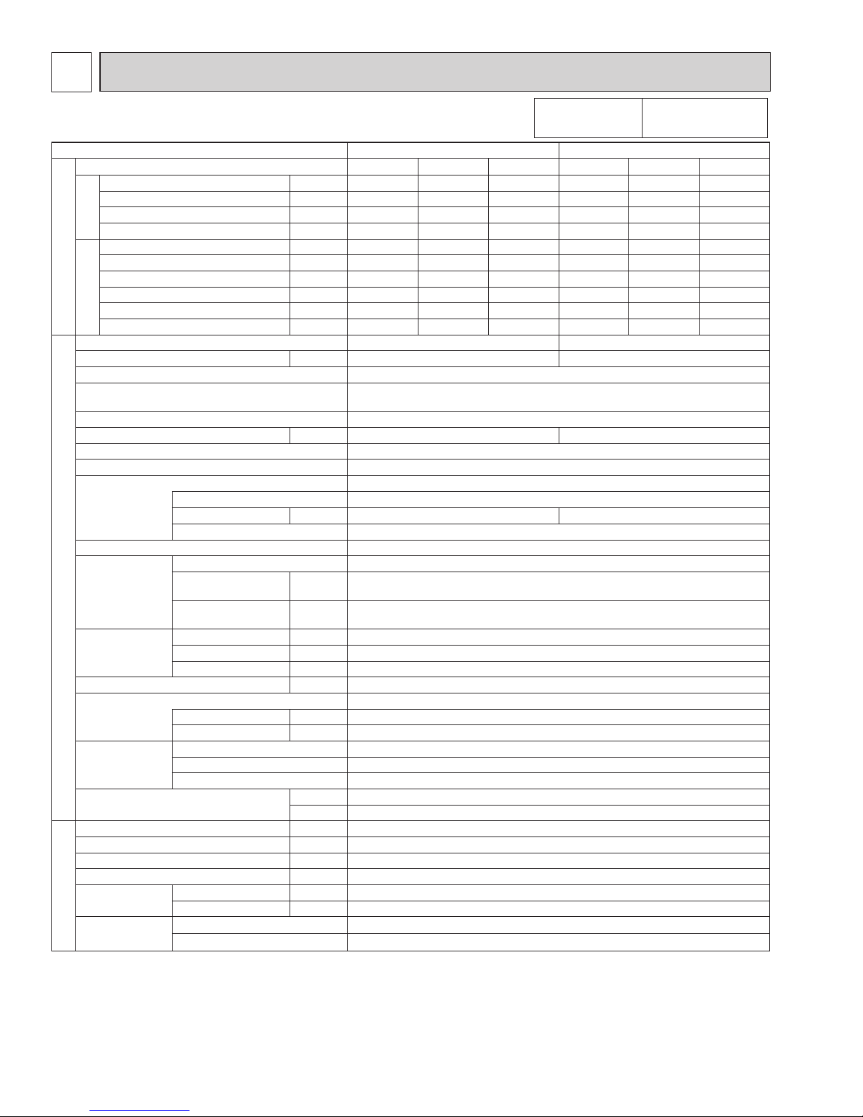
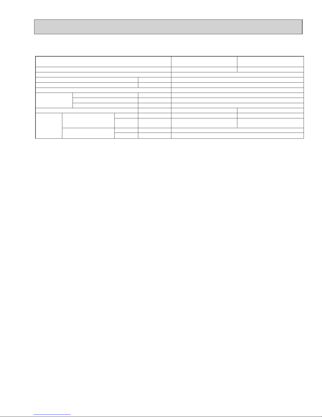
Connectable number of indoor units
Power supply
Input
Running current
External finish
Dimensions
Weight
Piping
connection
(Flare)
Width
Depth
Height
Branch (indoor side)
Main (outdoor side)
Liquid
Gas
Liquid
Gas
Maximum 3
15 (6.7 )
[1/4 (6.35)
× 3 {A,B,C}
[3/8 (9.52) × 3 {A,B,C}
Maximum 5
16 (7.4)
[1/4 (6.35) × 5 {A,B,C,D,E}
[ 3/8 (9.52) × 4 {A,B,C,D},
[ 1/2 (12.7) × 1{E}
PAC-MKA50BC
PAC-MKA51BC
PAC-MKA30BC
PAC-MKA31BC
Single phase, 208/230 V, 60 Hz
0.003
0.05
Galvanized sheets
17-23/32 (450)
11-1/32 (280)
6-11/16 (170)
[3/8 (9.52)
[ 5/8 (15.88)
*
Model name
3-2. BRANCH BOX: PAC-MKA50BC PAC-MKA51BC PAC-MKA30BC PAC-MKA31BC
*The piping connection size differs according to the type and capacity of indoor units. Match the piping connection size for indoor
and branch box. If the piping connection size of branch box does not match the piping connection size of indoor units, use
optional different-diameter (deformed) joints to the branch box side. (Connect deformed joint directly to the branch box side.)
OCH573C
14
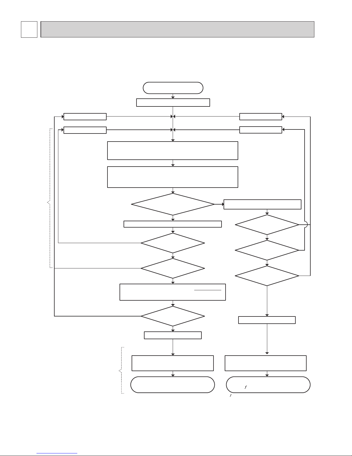
4
4-1. SELECTION OF COOLING/HEATING UNITS
DATA
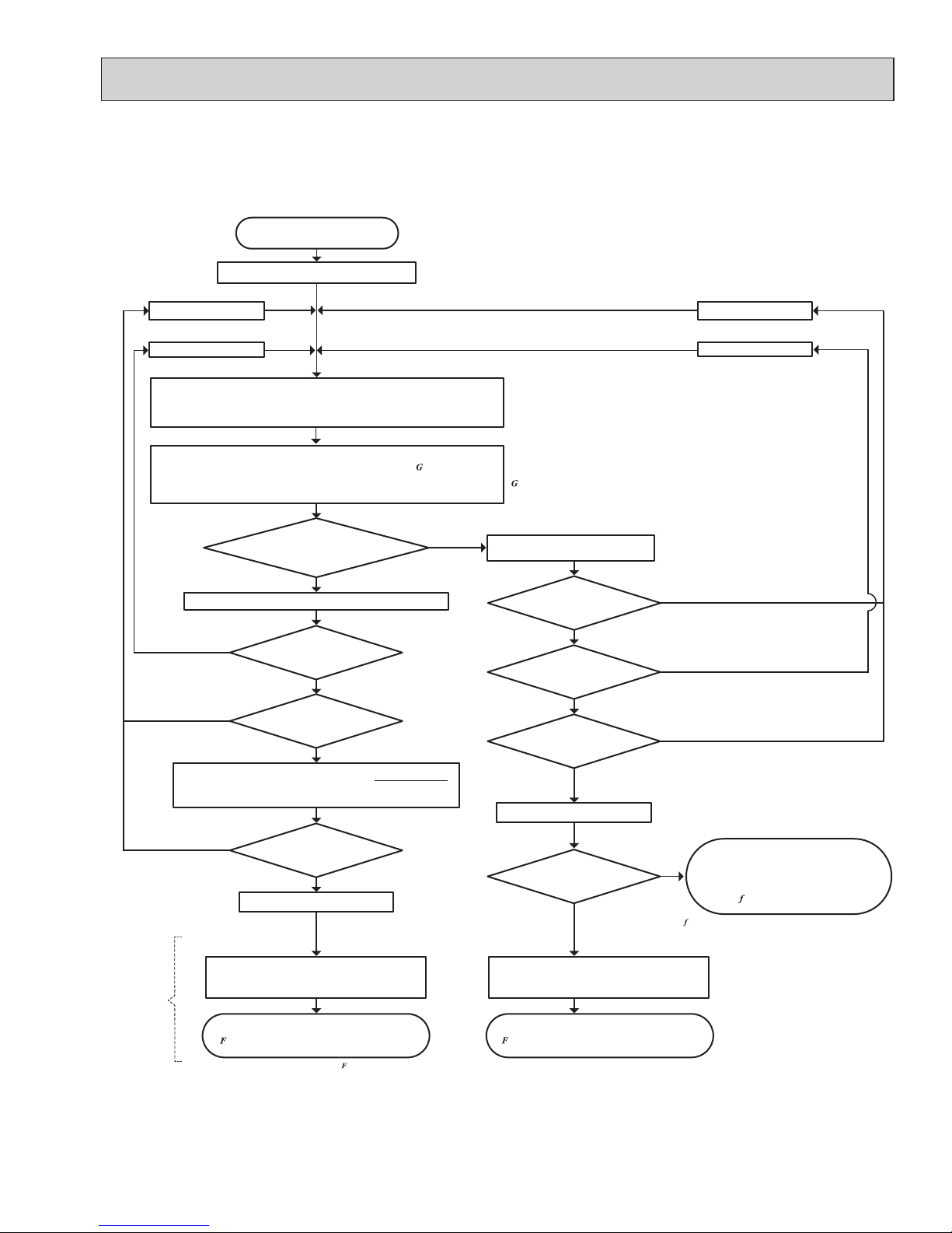
How to determine the capacity when less than or equal 100% indoor model size units are connected in total:
The purpose of this flow chart is to select the indoor and outdoor units. For other purposes, this flow chart is intended only for reference.
No
Yes
Temporarily select the Indoor/Outdoor Units
Reselect the outdoor units
Reselect the indoor units
Reselect the outdoor units
Reselect the indoor units
Indoor Unit
n
Total Indoor Units Capacity (CTi) = ∑ (Individual Rated Indoor Unit Capacity CTik ×
k=1
Individual Indoor Temperature Correction Coef.
α
k
) (Figure 1, 4)
Outdoor Unit
*1
Outdoor Unit Capacity (CTo) = Rated Outdoor Unit Capacity × Outdoor
Temperature Correction Coef. (Figure 2, 5) × Piping Length
Correction Coef. (Figure 3, 6) × Defrost Correction Coef. (in heating operation, Table 1)
Maximum Capacity(CT
max
) = CT
o
Yes
Completed Selecting Units
Want to change to smaller
indoor units?
Does it fulfill the load of
each room?
CT
o
≤ CT
i
L ≤ CT
o
Maximum Capacity(CT
max
) = CT
i
L ≤ CT
i
Need to select smaller
outdoor unit?
Does it fulfill the load of
each room?
Outdoor Unit Input = Rated Outdoor Unit Input ×
c
ave
Determine the load (L) and
the Indoor/Outdoor Temperature
n: Total Number of Indoor Units
k: Indoor Unit Number
Yes
No
No
No
No
Yes
No
No
Yes
Yes
Capacity
Determination
Input
Calculation
Average Indoor temp. power input Coef. (
c
ave
) Average Indoor temp. power input Coef. (
c
ave
)
c
ave
= ∑ {ck × (Mk/ ∑ Mk)}
n
k=1
n
k=1
c
ave
= ∑ {ck × (Mk/ ∑ Mk)}
n
k=1
n
k=1
(If indoor to outdoor connectable
capacity ratio is less than 100%, the
capacity correction is set as 100% )
*ck:
Outdoor unit power input coefficient of k indoor unit room temp. (Refer to 4-2.)
*Mk:
Number part of the k indoor unit model (e.g. P80 → 80)
∑ (CT
im
×
α
m
)
n
m=1
Individual Indoor Unit Capacity: CT'ik= CT
max
×
CTik ×
α
k
Outdoor Unit Input = Rated Outdoor Unit Input ×
c
ave
× (CTi )
Completed Selecting Units
(x) is the approximate correction function when less than or equal
100% model size units are input as connected.
Yes
OCH573C
15
How to determine the capacity when greater than 100% indoor model size units are connected in total:
No
Yes
Temporarily select the indoor/outdoor units
Reselect the outdoor units
Reselect the indoor units
Reselect the outdoor units
Reselect the indoor units
Indoor Unit
n
Total Indoor Units Capacity (CTi) = ∑ (Individual Rated Indoor Unit Capacity CT
ik
×
k=1
Individual Indoor Temperature Correction Coef.
α
k
) (Figure 1, 4)
Outdoor Unit
*1
Maximum Capacity(CT
max
) = CT
o
Yes
Want to change to smaller
indoor units?
Does it fulfill the load of
each room?
CT
o
≤ CT
i
L ≤ CT
o
Maximum Capacity(CT
max
) = CT
i
L ≤ CT
i
Need to select smaller
outdoor unit?
Does it fulfill the load of
each room?
Rated Outdoor Unit Capacity
< Total Indoor Units Capacity
Outdoor Unit Input
= Rated Outdoor Unit Input ×
Outdoor Temperature
Correction
Coef.
× (CT
i
)
Determine the load (L) and
the Indoor/Outdoor Temperature
n: Total Number of Indoor Units
k: Indoor Unit Number
Yes
Yes
No
No
No
No
Yes
No
No
No
Yes
Yes
Yes
Average Indoor temp. power input Coef. (
c
ave
)
= ∑ {c
k
× (Mk/ ∑ Mk)}
n
k=1
n
k=1
The purpose of this flow chart is to select the indoor and outdoor units. For other purposes, this flow chart is intended only for reference.
*ck:
Outdoor unit power input coefficient of k indoor unit room temp. (Refer to 4-2.)
*Mk:
Number part of the k indoor unit model (e.g. P80 → 80)
Average Indoor temp. power input Coef. (
c
ave
)
c
ave
= ∑ {ck × (Mk/ ∑ Mk)}
n
k=1
n
k=1
Outdoor Unit Input =Rated Outdoor Unit Input ×
c
ave
Outdoor Unit Input = Rated Outdoor Unit Input ×
c
ave
× (CTi )
∑ (CT
im
×
α
m
)
n
m=1
Individual Indoor Unit Capacity: CT'ik= CT
max
×
CTik ×
α
k
Completed Selecting Units
Completed Selecting Units
(x) is the approximate correction function when greater
than 100% model size units are connected.
Outdoor Unit Capacity (CTo) = Rated Outdoor Unit Capacity × ( )
× Outdoor Temperature Correction Coef. (Figure 2, 5)
× Piping Length Correction Coef. (Figure 3, 6) × Defrost Correction Coef. (in heating, Table 1)
(x) is the approximate correction function when greater than 100%
model size units are input as connected.
(x) is the approximate correction function when less than or equal
100% model size units are input as connected.
CT
i
× (CTi )
Input
Calculation
OCH573C
16
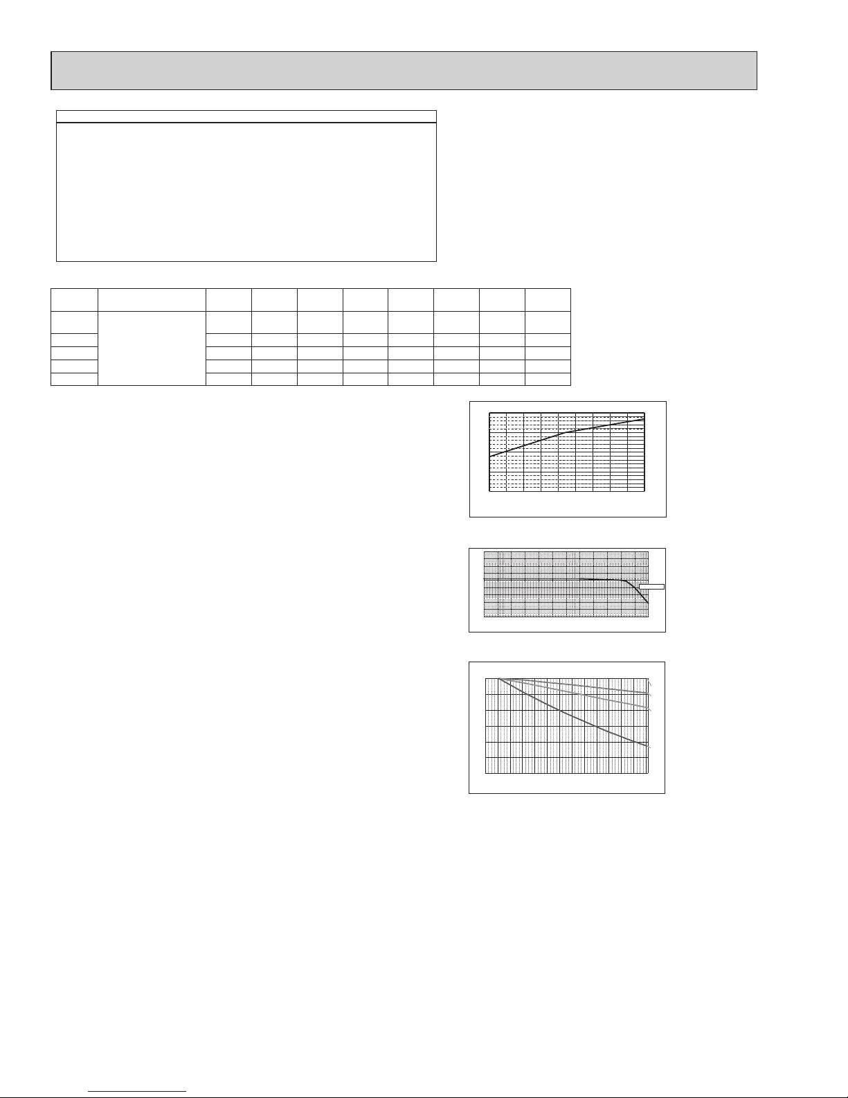
<Cooling>
Design Condition
Outdoor Design Dry Bulb Temperature 98.6ºF (37.0ºC)
Total Cooling Load 29.6 kBTU/h
Room1
Indoor Design Dry Bulb Temperature 80.6ºF (27.0ºC)
Indoor Design Wet Bulb Temperature 68.0ºF (20.0ºC)
Cooling Load 13.6 kBTU/h
Room2
Indoor Design Dry Bulb Temperature 75.2ºF (24.0ºC)
Indoor Design Wet Bulb Temperature 66.2ºF (19.0ºC)
Cooling Load 16.0 kBTU/h
<Other>
Indoor/Outdoor Equivalent Piping Length 250 ft
1. Cooling Calculation
(1) Temporary Selection of Indoor Units
Room1
MSZ-FH15
15.0 kBTU/h (Rated)
Room2
MSZ-FH18
17.2 kBTU/h (Rated)
(2) Total Indoor Units Capacity
15 + 18 = 33
(3) Selection of Outdoor Unit
The P36 outdoor unit is selected as total indoor units capacity is P33
MXZ-4C36
36.0 kBTU/h
(4) Total Indoor Units Capacity Correction Calculation
Room1
Indoor Design Wet Bulb Temperature Correction (68.0ºF)
1.02 (Refer to Figure 1)
Figure 1
Indoor unit temperature correction
To be used to correct indoor unit only
Figure 2 Outdoor unit temperature correction
To be used to correct outdoor unit only
Figure 3
Correction of refrigerant piping length
Room2
Indoor Design Wet Bulb Temperature Correction (66.2ºF)
0.95 (Refer to Figure 1)
CTi = Σ (Indoor Unit Rating × Indoor Design Temperature Correction)
= 15.0 × 1.02 + 17.2 × 0.95
= 31.6 kBTU/h
(5) Outdoor Unit Correction Calculation
Outdoor Design Dry Bulb Temperature Correction (98.6ºF)
0.98 (Refer to Figure 2)
Piping Length Correction (250 ft)
0.93 (Refer to Figure 3)
Total Outdoor Unit Capacity (CTo)
Total Indoor Units Capacity (CTi)
CTo = Outdoor Rating × Outdoor Design Temperature Correction × Piping Length Correction
= 36.0 × 0.98 × 0.93
= 32.8 kBTU/h
(6) Determination of Maximum System Capacity
Comparison of Capacity between Total Indoor Units Capacity (CTi) and Total Outdoor Unit Capacity (CTo)
CTi = 31.6 < CTo = 32.8, thus, select CTi.
CTx = CTi = 31.6 kBTU/h
(7) Comparison with Essential Load
Against the essential load 29.6 kBTU/h, the maximum system capacity is 31.6 kBTU/h: Proper outdoor units have been selected.
(8) Calculation of Maximum Indoor Unit Capacity of Each Room
CTx = CTi, thus, calculate by the calculation below
Room1
Indoor Unit Rating × Indoor Design Temperature Correction
= 15.0 × 1.02
= 15.3 kBTU/h
OK: fulfills the load 13.6 kBTU/h
Room2
Indoor Unit Rating × Indoor Design Temperature Correction
= 17.2 × 0.95
= 16.3 kBTU/h OK: fulfills the load 16.0 kBTU/h
Go on to the heating trial calculation since the selected units fulfill the cooling loads of Room 1, 2.
Indoor
Temperature
Ratio of cooling capacity
Indoor Temperature
[°F W.B.]
[°C W.B.]
-15 -10
-5 0 5 10 15 20 25 30 35 40 45
5 14
23 32 41 50 59 68 77 86 95 104 113
0.5
0.6
0.7
0.8
0.9
1.0
1.1
1.2
1.3
1.4
Ratio of cooling capacity
Outdoor Temperature
[°C D.B.]
[°F W.B.]
67.0°F(19.4°C) W.B
15 16 17 18 19 20 21 22 23 24
59 60.8 62.6 64.4 66.2 68 69.8 71.6 73.4 75.2
0.4
0.6
0.8
1.0
1.2
0 20 40 60 80 100 120 140 160 180 200 220 240 260
0.70
0.75
0.80
0.85
0.90
0.95
1.00
18 [kBTU/h]
27 [kBTU/h]
36 [kBTU/h]
Capacity ratio
Piping equivalent length (ft)
Total capacity of indoor unit
46.8 [kBTU/h]
Capacity of indoor unit
Model Number for indoor
unit
Model 06Model 09Model 12Model 15Model 18Model 24Model 30Model
36
M series Model Capacity [KBtu/h]
6.0 9.0 12.0
14.0*
1
15.0*
2
17.0*3
17.2*
4
22.5 ─ ─
P series ─ ─ 12.0 ─ 18.0 24.0 30.0 36.0
SEZ ─ 8.1 11.5 14.1 17.2 ─ ─ ─
SLZ ─ 8.4 11.1 15.0 ─ ─ ─ ─
MVZ ─ ─ 12.0 ─ 18.0 24.0 30.0 36.0
*1 For MSZ-GE/GL15NA
*
2
For the models other than
*1 above
*3 For MFZ-KA/KJ18NA
*
4
For the models other than
*3 above
OCH573C
17
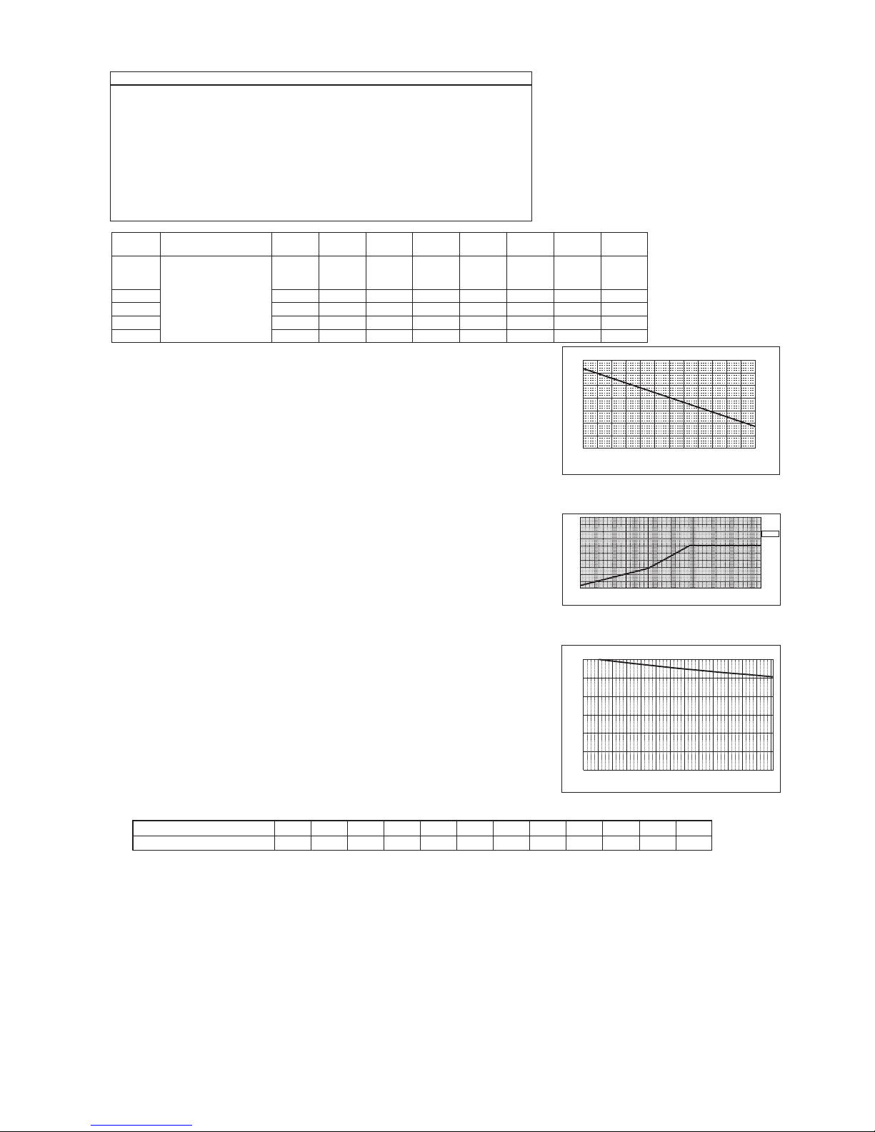
<Hea ting>
Design Condition
Outdoor Design W et Bulb Temperature 35.6ºF (2.0ºC)
Total Heating Load 34.4 kBTU/h
Room1
Indoor Design Dry Bulb Temperature 69.8ºF (21.0ºC)
Heating Load
16.3 kBTU/h
Room2
Indoor Design Dry Bulb Temperature 73.4ºF (23.0ºC)
Heating Load
18.1 kBTU/h
<Other>
Indoor/Outdoor Equivalent Piping Length 230 ft
2. Hea ting Calcula tion
(1) Temporary Selection of Indoor Units
Room1
MSZ-FH15 18.0 kBUT/h (Rated)
20.3 kBUT/h (Rated)
Room2
MSZ-FH18
(2) Total Indoor Units Capacity
15 + 18 = 33
(3) Selection of Outdoor Unit
The P36 outdoor unit is selected as total indoor units capacity is P33
MXZ-4C36 45.0 kBUT/h
(4) Total Indoor Units Capacity Correction Calculation
Room1
Indoor Design Dry Bulb Temperature Correction (69.8ºF)
1.00 (Refer to Figure 4)
Room2
Indoor Design Dry Bulb Temperature Correction (73.4ºF)
0.92 (Refer to Figure 4)
CTi = Σ (Indoor Unit Rating × Indoor Design Temperature Correction)
= 18.0 × 1.00 + 20.3 × 0.92
= 36.7 kBTU/h
(5) Outdoor Unit Correction Calculation
Outdoor Design Wet Bulb Temperature Correction (35.6ºF)
1.0 (Refer to Figure 5)
Piping Length Correction (230 ft)
Defrost Correction
0.96 (Refer to Figure 6)
0.89 (Refer to Table 1)
Total Outdoor Unit Capacity (CTo)
Total Indoor Units Capacity (CTi)
CTo = Outdoor Unit Rating × Outdoor Design Temperature Correction × Piping Length
Correction × Defrost Correction
= 45.0 × 1.0 × 0.96 × 0.89
= 38.4 kBTU/h
(6) Determination of Maximum System Capacity
Comparison of Capacity between Total Indoor Units Capacity (CTi) and Total Outdoor Unit Capacity (CTo)
CTi = 36.7 < CTo = 38.4, thus, select CTi.
CTx = CTi = 36.7 kBTU/h
(7) Comparison with Essential Load
Against the essential load 34.4 kBTU/h, the maximum system capacity is 36.7 kBTU/h: Proper outdoor units have been selected.
(8) Calculation of Maximum Indoor Unit Capacity of Each Room
CTx = CTi, thus, calculate by the calculation below
Room1
Maximum Capacity × Room1 Capacity after the Temperature Correction/(Room1,2 Total Capacity after the Temperature Correction
= 36.7 × (18.0 × 1.00) / (18.0 × 1.00 + 20.3 × 0.92)
= 18.0 kBTU/h OK: fulfills the load 16.3 kBTU/h
Room2
Maximum Capacity × Room1 Capacity after the Temperature Correction/(Room1,2 Total Capacity after the Temperature Correction
= 36.7 × (20.3 × 0.92) / (18.0 × 1.00 + 20.3 × 0.92)
= 18.7 kBTU/h OK: fulfills the load 18.1 kBTU/h
Completed selecting units since the selected units fulfill the heating loads of Room 1, 2.
Figure 4 Indoor unit temperature correction
To be used to correct indoor unit only
Figure 5 Outdoor unit temperature correction
To be used to correct outdoor unit only
Figure 6 Correction of refrigerant piping length
-4 5 14 23 32 41 50 59
-25
-20 -15 -10 -5 0 5 10 15
0.4
0.5
0.6
0.7
0.8
0.9
0.8
0.5
0.6
0.7
1.0
1.1
1.2
1.0
1.1
1.3
1.4
Ratio of heating capacity
Outdoor Temperature [°C W.B.]
70.0°F (21.1°C) D.B
15 16 17 18 19 20 21 22 23 24 25 26 27
59 60.8 62.6 64.4 66.2 68 69.8 71.6 73.4 75.2 77 78.8 80.6
0.6
0.7
0.8
0.9
1.0
1.1
1.2
1.3
Ratio of heating capacity
Indoor Temperature
[°C D.B.]
[°F W.B.]
[°C D.B.]
[°F W.B.]
Indoor
Temperature
0 20 40 60 80 100 120 140 160 180 200 220 240 260
0.70
0.75
0.80
0.85
0.90
0.95
1.00
Total capacity of indoor unit
Capacity ratio
Piping equivalent length (ft)
Table 1 Table of correction factor at frost and defrost
Outdoor Intake temperature <W.B.°F (°C)>
43(6) 37(4) 36(2) 32(0) 28(−2) 25(−4) 21(−6) 18(−8) 14(−10) 5(−15) −4(−20) −13(−25)
Correction factor
1.0 0.98 0.89 0.88 0.89 0.9 0.95 0.95 0.95 0.95 0.95 0.95
Capacity of indoor unit
Model Number for indoor
unit
Model 06Model 09Model 12Model 15Model 18Model 24Model 30Model
36
M series Model Capacity [KBtu/h]
6.0 10.9
13.6*
1
14.4*
2
13.0*
3
18
20.3*
1
21.6*
2
21.0*
3
27.6 ─ ─
P series ─ ─ 13.5 ─ 18.0 26.0 34.0 40.0
SEZ ─ 10.9 13.6 18.0 17.2 ─ ─ ─
SLZ ─ 10.2 13.7 17.1 ─ ─ ─ ─
MVZ ─ ─ 12.0 ─ 18.0 27.0 34.0 40.0
*1 For MSZ-FH/FE12,18NA
*
2
For MSZ-GE/GL12,18NA
*
3
For the models other than
*1 and
*2 above
OCH573C

18
n: Total number of the indoor units
k: Number of the indoor unit
c
k
: Outdoor unit power input coefficient of k indoor unit room temp.
M
k
: Number part of the k indoor unit model (e.g. P80 → 80)
<Cooling>
3. Power input of outdoor unit
Outdoor unit : MXZ-4C36
Indoor unit 1 : MSZ-FH15
Indoor unit 2 : MSZ-FH18
(1) Rated power input of outdoor unit 2.57 kW
1.04 (Refer to “4-2. CORRECTING BY TEMPERATURE”.)
(2) Calculation of the average indoor temperature power input coefficient
Coefficient of the outdoor unit for indoor unit 1 (Outdoor temp. 98.6°F [37.0°C] D.B., Indoor temp. 68.0°F [20.0°C] W.B.)
Maximum System Capacity (CTx) = Total Outdoor unit Capacity (CTo), so use the following formula
Total Indoor units capacity
15 + 18 = 33, thus, (CTi) = 0.9 (Refer to the tables in “4-4.STANDARD CAPACITY DIAGRAM”.)
PIo = Outdoor unit Cooling Rated Power Input × Correction Coefficient of Indoor temperature × (CTi)
= 2.57 × 0.94 × 0.9
= 2.2 kW
0.85 (Refer to “4-2. CORRECTING BY TEMPERATURE”.)
Coefficient of th
e outdoor unit for indoor unit 2 (Outdoor temp. 98.6°F [37.0°C] D.B., Indoor temp. 64.4°F [18.0°C] W.B.)
= 1.04 × 15/(15 + 18) + 0.85 × 18/(15 + 18)
= 0.94
n
k=1
n
k=1
Average indoor temp. power input coefficient (
c
ave
)
= ∑ {ck × (Mk/ ∑ Mk)}
(4) Outdoor power input (PIo)
(3) Coefficient of the partial load (CTi)
OCH573C

19
n: Total number of the indoor units
k: Number of the indoor unit
c
k
: Outdoor unit power input coefficient of k indoor unit room temp.
M
k
: Number part of the k indoor unit model (e.g. P80 → 80)
<Heating>
(1) Rated power input of outdoor unit 3.34 kW
1.34 (Refer to “4-2. CORRECTING BY TEMPERATURE”.)
(2) Calculation of the average indoor temperature power input coefficient
Coefficient of the outdoor unit for indoor unit 1 (Outdoor temp. 26.6°F [−3°C] W.B., Indoor temp. 68.0°F [20°C] D.B.)
Maximum System Capacity (CTx) = Total Indoor unit Capacity (CTi), so use the following formula
PIo = Outdoor unit Heating Rated Power Input × Correction Coefficient of Indoor temperature × (CTi)
= 3.34 × 1.20 × 0.9
= 3.61 kW
1.09 (Refer to “4-2. CORRECTING BY TEMPERATURE”.)
Coefficient of the outdoor unit for indoor unit 2 (Outdoor temp. 26.6°F [−3°C] W.B., Indoor temp. 77.0°F [25°C] D.B.)
= 1.34 × 15/(15 + 18) + 1.09 × 18/(15 + 18)
= 1.20
n
k=1
n
k=1
Average indoor temp. power input coefficient (
c
ave
)
= ∑ {ck × (Mk/ ∑ Mk)}
(4) Outdoor power input (PIo)
(3) Coefficient of the partial load (CTi)
Total indoor units capacity
15 + 18 = 33, thus, (CTi) = 0.9 (Refer to the tables in “4-4. STANDARD CAPACITY TEMPERATURE”.)
OCH573C
20
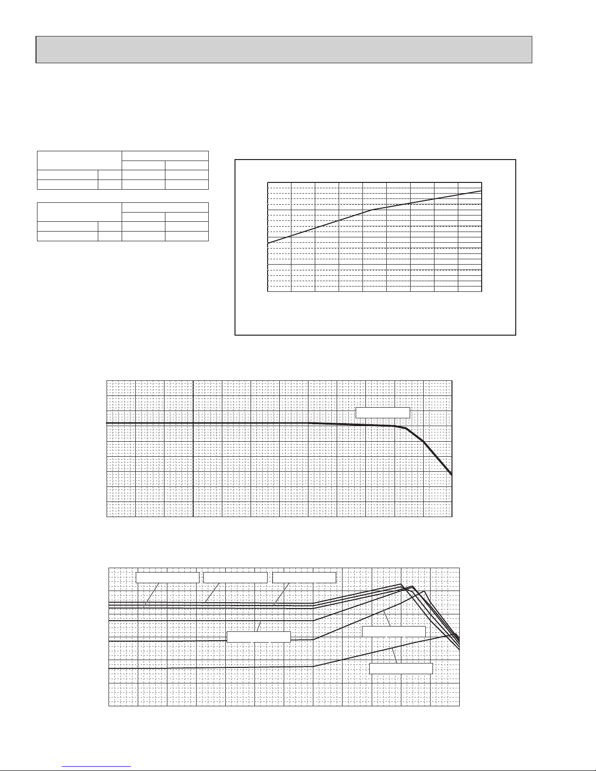
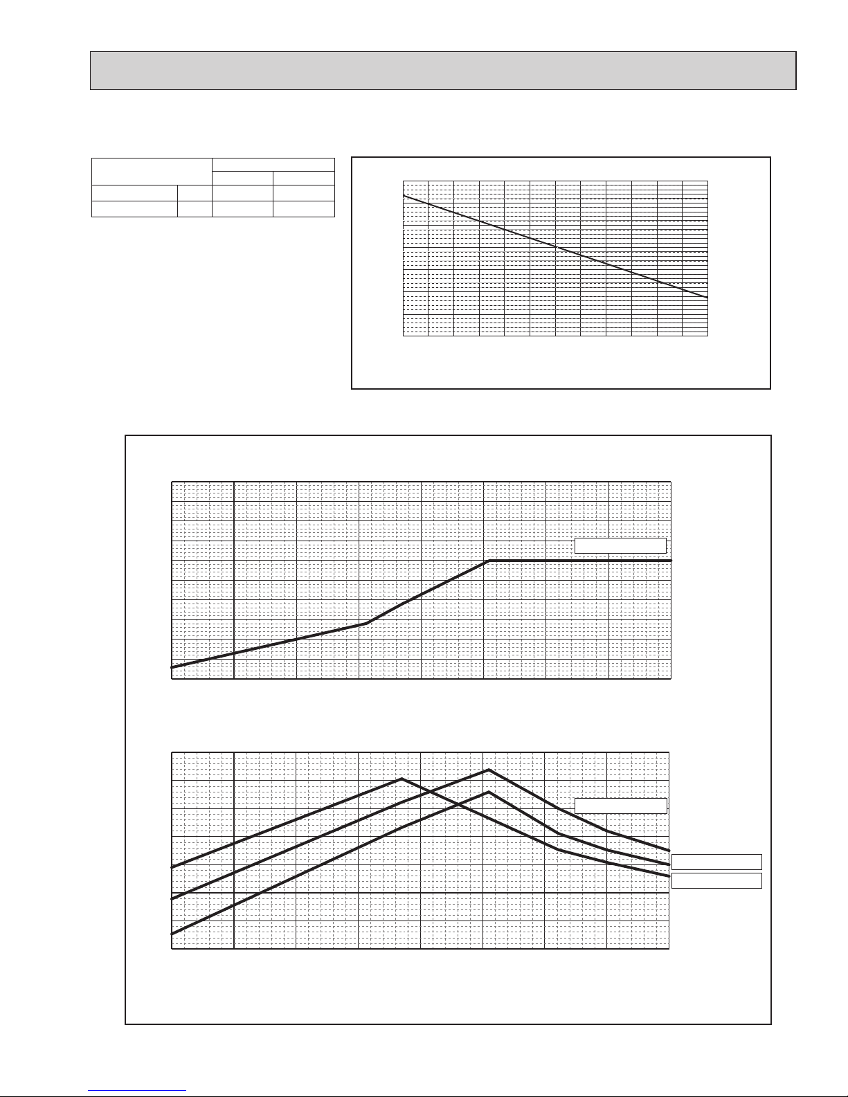
4-2. CORRECTING BY TEMPERATURE
15 16 17 18 19 20 21 22 23 24
59 60.8 62.6 64.4 66.2 68 69.8 71.6 73.4 75.2
0.4
0.6
0.8
1.0
1.2
Ratio of cooling capacity
Indoor Temperature
[°CW.B.]
[°FW.B.]
5 14
23 32 41 50 59 68 77 86 95 104 113
-15 -10
-5 0 5 10 15 20 25 30 35 40 45
0.4
0.5
0.6
0.7
0.8
0.9
1.0
1.1
1.2
1.3
Ratio of cooling capacity
Outdoor Temperature
67.0°F (19.4°C) W.B.
[°C W.B.]
[°F W.B.]
-15 -10
-5 0 5 10 15 20 25 30 35 40 45
5 14
23 32 41 50 59 68 77 86 95 104 113
0.0
0.2
0.4
0.6
0.8
1.0
1.2
Ratio of power input
Outdoor Temperature
[°C W.B.]
[°F W.B.]
68.0°F (20.0°C) W.B.68.0°F (20.0°C) W.B. 75.2°F (24.0°C) W.B.75.2°F (24.0°C) W.B.
71.6°F (22.0°C) W.B.71.6°F (22.0°C) W.B.
67.0°F (19.4°C) W.B.67.0°F (19.4°C) W.B.
64.4°F (18.0°C) W.B.64.4°F (18.0°C) W.B.
60.8°F (16.0°C) W.B.60.8°F (16.0°C) W.B.
MXZ-4C36/5C42/8C48NA(HZ), 8C60NA could have varied capacity at different designing temperature. Using the nominal
cooling/heating capacity value and the ratio below, the capacity can be observed at various temperature.
MXZ
4C36 5C42
Nominal cooling capacity
BTU/h 36,000 48,000
Input kW 2.57 3.13
Figure 7 Indoor unit temperature correction
To be used to correct indoor unit capacity only
Figure 8 Outdoor unit temperature correction
To be used to correct outdoor unit capacity only
<Cooling>
Indoor Temperature
Indoor Temperature
MXZ
8C48 8C60
Nominal cooling capacity
BTU/h 48,000 60,000
Input kW 4.00 4.80
OCH573C
21
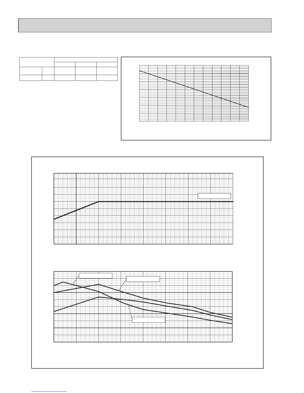
<Heating>
15 16 17 18 19 20 21 22 23 24 25 26 27
59 60.8 62.6 64.4 66.2 68 69.8 71.6 73.4 75.2 77 78.8 80.6
0.6
0.7
0.8
0.9
1.0
1.1
1.2
1.3
Ratio of heating capacity
Indoor Temperature
[°C W.B.]
[°F W.B.]
-25
-20 -15 -10 -5 0 5 10
15
-13
-4 5 14 23 3 41 50
59
0.4
0.5
0.6
0.7
0.8
0.9
1.0
1.1
1.2
1.3
1.4
Ratio of heating capacity
Outdoor Temperature
[°C W.B.]
[°F W.B.]
70.0°F (21.1°C) D.B.
-25
-20 -15 -10 -5 0 5 10
15
-13
-4 5 14 23 3 41 50
59
0.0
0.2
0.4
1.0
0.6
0.8
1.2
1.4
Ratio of power input
Outdoor Temperature
[°C W.B.]
[°F W.B.]
70.0°F (21.1°C) D.B.
60.8°F (16.0°C) D.B.
78.8°F (26.0°C) D.B.
Figure 9 Indoor unit temperature correction
To be used to correct indoor unit capacity only
Figure 10 Outdoor unit temperature correction
To be used to correct outdoor unit capacity only
MXZ
8C48NA 8C60NA
Nominal heating capacity
BTU/h 54,000 66,000
Input kW
4.22 5.67
Indoor Temperature
Indoor Temperature
OCH573C
22
<Heating> (NAHZ)
15 16 17 18 19 20 21 22 23 24 25 26 27
59 60.8 62.6 64.4 66.2 68 69.8 71.6 73.4 75.2 77 78.8 80.6
0.6
0.7
0.8
0.9
1.0
1.1
1.2
1.3
Ratio of heating capacity
Indoor Temperature
[°C W.B.]
[°F W.B.]
-25
-20 -15 -10 -5 0 5 10
15
0.4
1.3
-13
-4 5 14 23 3 41 50
59
0.5
0.6
0.7
0.8
0.9
1.0
1.1
1.2
1.4
Ratio of heating capacity
Outdoor Temperature
[°C W.B.]
[°F W.B.]
70.0°F (21.1°C) D.B.
Ratio of power input
Outdoor intake air dry-bulb temperature
-13 -14 5 14 23 32 41 50 59
-25
-20 -15 -10 -5 0 5 10
15
0.0
0.2
0.4
0.6
0.8
1.0
1.2
1.4
1.6
1.8
2.0
[°C W.B.]
[°F W.B.]
60.8°F (16.0°C) W.B.
69.8°F (21.0°C) W.B.
78.8°F (26.0°C) W.B.
Figure 11 Indoor unit temperature correction
To be used to correct indoor unit capacity only
Figure 12 Outdoor unit temperature correction
To be used to correct outdoor unit capacity only
MXZ
4C36NAHZ 5C42NAHZ 8C48NAHZ
Nominal heating
capacity
BTU/h 45,000 48,000 54,000
Input kW
3.34 3.43 4.22
Indoor Temperature
Indoor Temperature
OCH573C

23
Operation
Outdoor unit model
MXZ-4C36NAHZ MXZ-5C42NAHZ
Operating
conditions
Ambient
temperature
Indoor
DB/WB
80°F/67°F 70°F/60°F 80°F/67°F 70°F/60°F
Outdoor 95°F/75°F 47°F/43°F 95°F/75°F 47°F/43°F
Indoor unit
No. of connected units
Unit
4 4
No. of units in operation
4 4
Model — 09 × 4 09 × 2 + 12 ×2
Piping
Main pipe
m
9.84 (3) 9.84 (3)
Branch pipe 14.76 (4.5) 14.76 (4.5)
Total pipe length 68.90 (21) 68.90 (21)
Fan speed — Hi Hi
Amount of refrigerant
lb oz
(kg)
17 lb 7 oz (7.9) 17 lb 7 oz (7.9)
Outdoor unit
Electric current A 14.1 18.7 17.2 19.1
Voltage V 230 230
Compressor frequency Hz 59 74 70 80
LEV
opening
Indoor unit Pulse 112 128 129 128
Pressure High pressure/Low pressure
MPaG 2.57/0.98 2.78/0.64 2.72/0.80 2.80/0.56
PSIG 373/142 403/93 395/116 406/81
Temp. of
each section
Outdoor
unit
Discharge
°F
[°C]
143.8 [62.1] 151.5 [66.4] 148.6 [64.8] 145.8 [63.2]
Heat exchanger outlet 100.8 [38.2] 36.7 [2.6] 101.8 [38.8] 35.6 [2.0]
Accumulator inlet 50.5 [10.3] 36.1 [2.3] 49.5 [9.7] 34.9 [1.6]
Compressor inlet 47.1 [8.4] 34.0 [1.1] 45.3 [7.4] 32.7 [0.4]
Indoor unit
LEV inlet 70.0 [21.1] 103.5 [39.7] 83.7 [28.7] 100.2 [37.9]
Heat exchanger inlet 54.1 [12.3] 138.9 [59.4] 49.6 [9.8] 132.3 [55.7]
4-3. STANDARD OPERATION DATA (REFERENCE DATA)
Operation
Outdoor unit model
MXZ-8C48NA/NAHZ MXZ-8C60NA
Operating
conditions
Ambient
temperature
Indoor
DB/WB
80°F/67°F 70°F/60°F 80°F/67°F 70°F/60°F
Outdoor 95°F/75°F 47°F/43°F 95°F/75°F 47°F/43°F
Indoor unit
No. of connected units
Unit
4 5
No. of units in operation
4 5
Model — 12 × 4 09 × 3 + 15 + 18
Piping
Main pipe
m
9.84 (3) 9.84 (3)
Branch pipe 14.76 (4.5) 14.76 (4.5)
Total pipe length 68.90 (21) 83.79 (25.5)
Fan speed — Hi Hi
Amount of refrigerant
lb oz
(kg)
17 lb 7 oz (7.9) 20 lb (8.9)
Outdoor unit
Electric current A 22.1 21.9 20.4 24.4
Voltage V 230 230
Compressor frequency Hz 86 91 45 51
LEV
opening
Indoor unit Pulse 11 2 132 187 229
Pressure High pressure/Low pressure
MPaG 2.83/0.77 2.82/0.55 2.84/0.92 2.44/0.672
PSIG 410/112 409/80 412/134 354/97.5
Temp. of
each section
Outdoor
unit
Discharge
°F
[°C]
157.6 [69.8] 149.2 [65.1] 167 [75.0] 133.9 [56.6]
Heat exchanger outlet 105.6 [40.9] 34.3 [1.3] 98.8 [37.1] 51.1 [10.2]
Accumulator inlet 47.1 [8.4] 33.4 [0.8] 49.5 [9.7] 32.4 [0.2]
Compressor inlet 42.4 [5.8] 30.6 [−0.8] 72.5 [22.5] 31.6 [−0.2]
Indoor unit
LEV inlet 71.1 [21.7] 98.8 [37.1] 59.7 [15.4] 81.9 [27.7]
Heat exchanger inlet 47.5 [8.6] 134.6 [57.0] 52.5 [11.4] 104.2 [40.1]
OCH573C
24
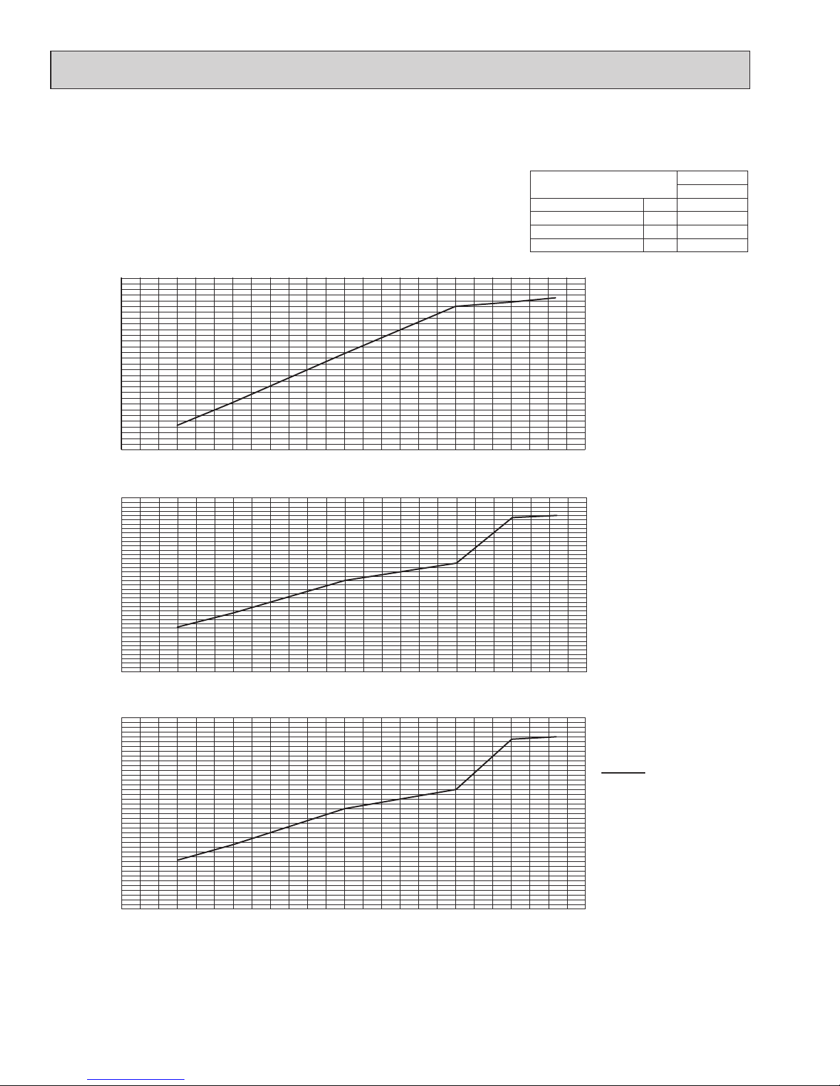
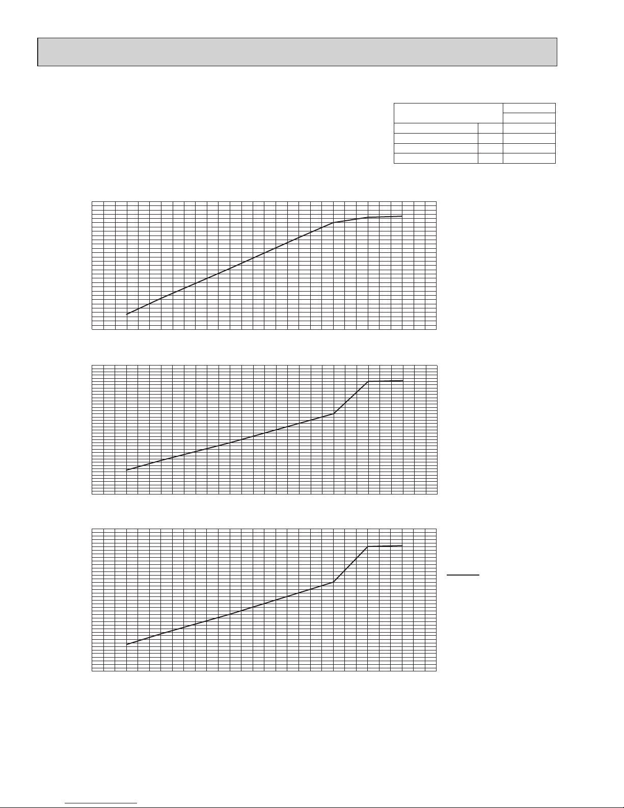
4-4. STANDARD CAPACITY DIAGRAM
Before calculating the sum of total capacity of indoor units, please convert the value into the kW model capacity following the formula on
"4-1. Method for obtaining system cooling and heating capacity".
4-4-1. MXZ-4C36NAHZ <cooling>
Ratio of capacity
Total capacity of indoor units (kBTU/h)
Total capacity of indoor units (kBTU/h)
Ratio of power inputRatio of current
Total capacity of indoor units (kBTU/h)
0
10
20
30
40 50
0.0
0.2
0.4
0.6
0.8
1.0
1.2
1.4
1.6
0 10 20
30
40 50
0.0
0.2
0.4
0.6
0.8
1.0
0 10 20
30
40 50
0.0
0.2
0.4
0.6
0.8
1.0
1.2
1.4
1.6
MXZ
4C36NAHZ
Nominal cooling capacity BTU/h 36,000
Input kW 2.57
Current (208V) A 12.8
Current (230V) A 11.6
208, 230 V
OCH573C
25
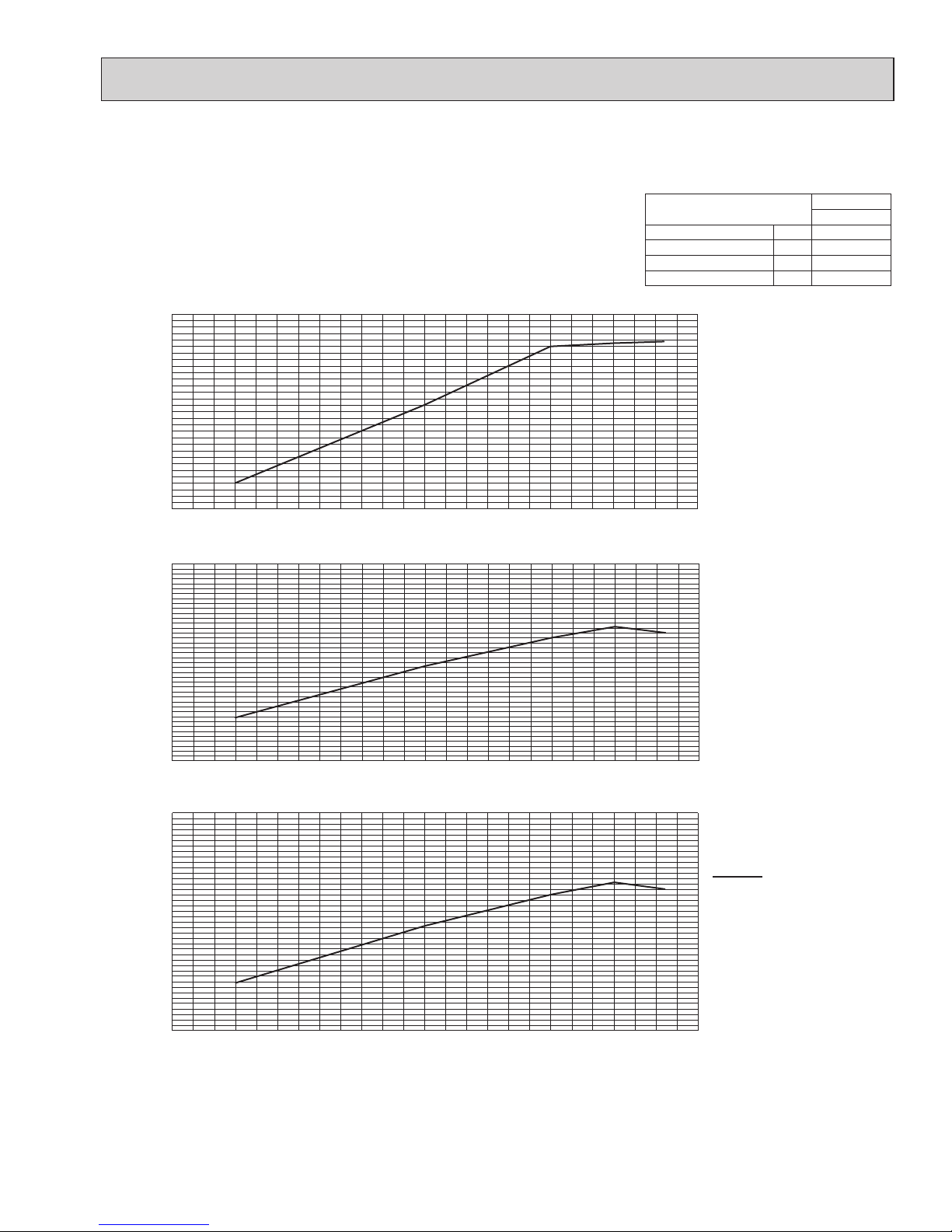
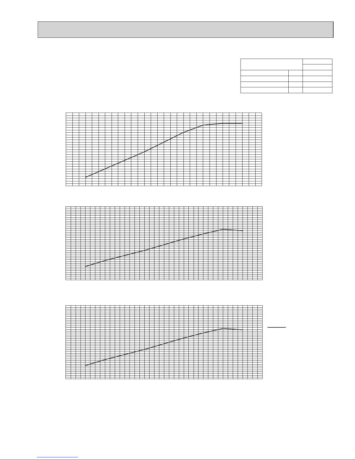
4-4-2. MXZ-4C36NAHZ <heating>
MXZ
4C36NAHZ
Nominal cooling capacity BTU/h 45,000
Input kW 3.34
Current (208V) A 16.4
Current (230V) A 14.8
Total capacity of indoor units (kBTU/h)
Total capacity of indoor units (kBTU/h)
Total capacity of indoor units (kBTU/h)
0
10
20
30
40 50
0.0
0.2
0.4
0.6
0.8
1.0
1.2
1.4
1.6
0 10 20
30
40 50
0.0
0.2
0.4
0.6
0.8
1.0
0 10 20
30
40 50
0.0
0.2
0.4
0.6
0.8
1.0
1.2
1.4
1.6
Ratio of capacity
Ratio of power inputRatio of current
208, 230 V
OCH573C
26
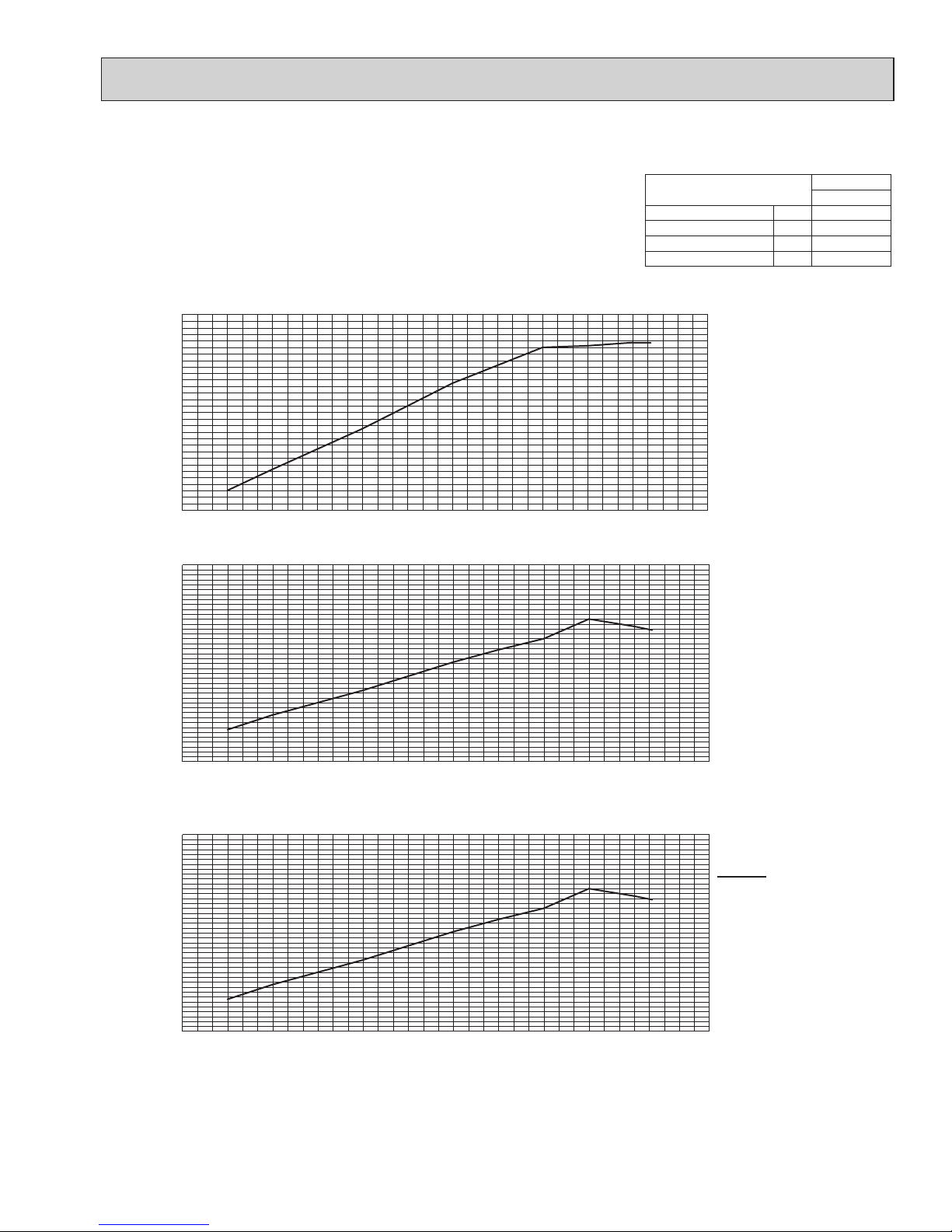
4-4-3. MXZ-5C42NAHZ <cooling>
Total capacity of indoor units (kBTU/h)
Total capacity of indoor units (kBTU/h)
Total capacity of indoor units (kBTU/h)
0
10
20
30
40 50
60
0.0
0.2
0.4
0.6
0.8
1.0
1.2
1.4
1.6
0 10 20
30
40 50
60
0.0
0.2
0.4
0.6
0.8
1.0
1.2
0 10 20
30
40 50
60
0.0
0.2
0.4
0.6
0.8
1.0
1.2
1.4
1.6
Ratio of capacity
Ratio of power inputRatio of current
MXZ
5C42NAHZ
Nominal cooling capacity BTU/h 42,000
Input kW 3.13
Current (208V) A 15.4
Current (230V) A 14.0
208, 230 V
OCH573C
27
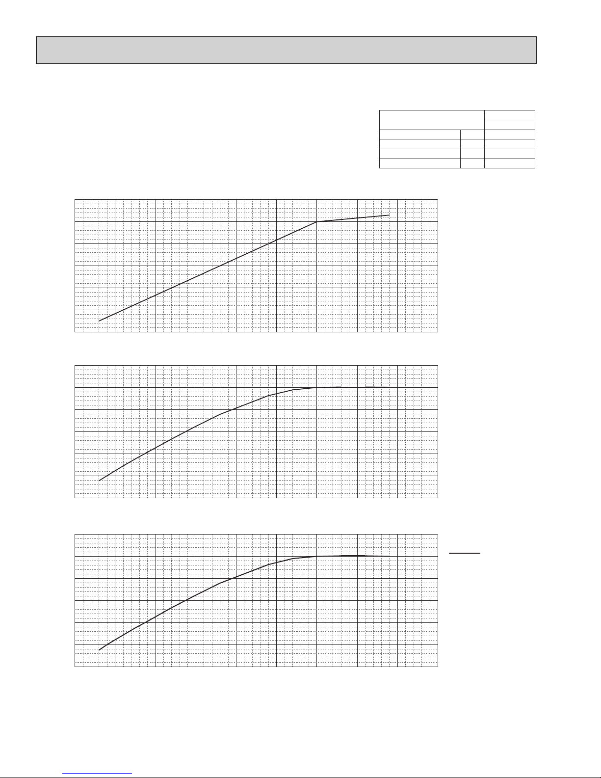
4-4-4. MXZ-5C42NAHZ <heating>
MXZ
5C42NAHZ
Nominal cooling capacity BTU/h 48,000
Input kW 3.43
Current (208V) A 16.8
Current (230V) A 15.2
Total capacity of indoor units (kBTU/h)
Total capacity of indoor units (kBTU/h)
Total capacity of indoor units (kBTU/h)
0 10 20
30
40 50
60
0.0
0.2
0.4
0.6
0.8
1.0
1.2
0.0 7.5 15.0 22.5
30.0
37.5 45.0 52.5
60.0
0.0
0.2
0.4
0.6
0.8
1.0
1.2
1.4
1.6
0.0 7.5 15.0 22.5
30.0
37.5 45.0 52.5
60.0
0.0
0.2
0.4
0.6
0.8
1.0
1.2
1.4
1.6
Ratio of capacity
Ratio of power inputRatio of current
208, 230 V
OCH573C

28
4-4-5. MXZ-8C48NA MXZ-8C48NAHZ <cooling>
Total capacity of indoor units (kBTU/h)
Total capacity of indoor units (kBTU/h)
Total capacity of indoor units (kBTU/h)
Ratio of capacity
Ratio of power inputRatio of current
0 10 20
30
40 50
60
70
0.0
0.2
0.4
0.6
0.8
1.0
1.2
0 10 20 30 40 50
60
70
0.0
0.2
0.4
0.6
0.8
1.0
1.2
1.4
1.6
0 10 20 30 40 50
60
70
0.0
0.2
0.4
0.6
0.8
1.0
1.2
1.4
1.6
MXZ
8C48NAHZ
Nominal cooling capacity BTU/h 48,000
Input kW 4.00
Current (208V) A 19.5
Current (230V) A 17.6
208, 230 V
OCH573C
29
4-4-6. MXZ-8C48NA MXZ-8C48NAHZ <heating>
Total capacity of indoor units (kBTU/h)
Total capacity of indoor units (kBTU/h)
Total capacity of indoor units (kBTU/h)
Ratio of capacity
Ratio of power inputRatio of current
0 10 20
30
40 50
60
70
0.0
0.2
0.4
0.6
0.8
1.0
1.2
0 10 20
30
40 50
60
70
0.0
0.2
0.4
0.6
0.8
1.0
1.2
1.4
1.6
0 10 20
30
40 50
60
70
0.0
0.2
0.4
0.6
0.8
1.0
1.2
1.4
1.6
MXZ
8C48NA(HZ)
Nominal cooling capacity BTU/h 54,000
Input kW 4.22
Current (208V) A 20.5
Current (230V) A 18.6
208, 230 V
OCH573C
30
4-4-7. MXZ-8C60NA <cooling>
0.0 10.0 20.0 30.0 40.0 50.0 60.0 70.0 80.0 90.0
0.0
0.2
0.4
0.6
0.8
1.0
1.2
0.0 10.0 20.0 30.0 40.0 50.0 60.0 70.0 80.0 90.0
0.0
0.2
0.4
0.6
0.8
1.0
0.0 10.0 20.0 30.0 40.0 50.0 60.0 70.0 80.0 90.0
0.0
0.2
0.4
0.6
0.8
1.0
Total capacity of indoor units(kBTU/h)
Total capacity of indoor units(kBTU/h)
Total capacity of indoor units(kBTU/h)
Ratio of capacity
Ratio of power inputRatio of current
MXZ
8C60NA
Nominal cooling capacity BTU/h 60,000
Input kW 4.80
Current (208V) A 24.1
Current (230V) A 21.8
208, 230 V
OCH573C
 Loading...