

Mitsubishi Electric MXZ-8A140VA, MXZ-8A140VA3, PAC-AK50BC, PAC-AK30BC, MXZ-8A140VA1 Service Manual
...
SPLIT-TYPE, HEAT PUMP AIR CONDITIONERS
HFC
utilized
R410A
TECHNICAL & SERVICE MANUAL
August 2007
No. OC316
REVISED EDITION-D
[Model name] [Service Ref.]
<Outdoor unit>
MXZ-8A140VA MXZ-8A140VA
MXZ-8A140VA
MXZ-8A140VA2
MXZ-8A140VA3
<Branch box>
PAC-AK50BC PAC-AK50BC
PAC-AK30BC PAC-AK30BC
(Indispensable optional parts
for MXZ-8A140VA)
CONTENTS
1. TECHNICAL CHANGES···································2
2. SAFETY PRECAUTION ····································3
3. OVERVIEW OF UNITS······································6
4. SPECIFICATIONS···········································14
5. DATA ·······························································16
6. OUTLINES AND DIMENSIONS······················31
7. WIRING DIAGRAM·········································34
8.
NECESSARY CONDITIONS FOR SYSTEM CONSTRUCTION
9. TROUBLESHOOTING ····································40
10. ELECTRICAL WIRING ····································88
11. WIRING SPECIFICATIONS·····························89
12. SYSTEM CONTROL ·······································90
13. REFRIGERANT PIPING TASK·······················92
14. DISASSEMBLY PROCEDURE ·······················95
15. PARTS LIST ··················································102
16. RoHS PARTS LIST ·······································109
17. OPTIONAL PARTS··························Back cover
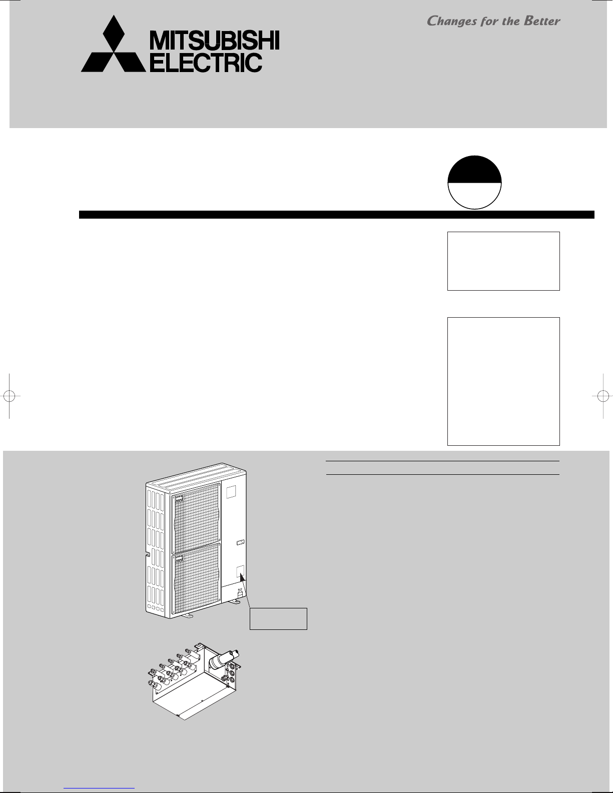
OUTDOOR UNIT
Model name
indication
Revision:
· MXZ-8A140VA
REVISED EDITION-D.
· Some descriptions have
been modified.
1
· Please void OC316
REVISED EDITION-C.
NOTE:
·This service manual
describes technical data of
outdoor unit and branch box.
As for indoor units, refer to
its service manual.
• RoHS compliant products
have <G> mark on the
spec name plate.
• For servicing RoHS compliant products, refer to the
RoHS PARTS LIST.
3 is added in
···38
BRANCH BOX

1 TECHNICAL CHANGES
MXZ-8A140VA2 ➔ MXZ-8A140VA3
The parts below have been changed.
• THERMISTOR (DISCHARGE/TH4) (Connector change)
• CONTROLLER CIRCUIT BOARD(C.B)
• NOISE FILTER CIRCUIT BOARD(N.F.)
• ACTIVE FILTER MODULE(ACTM)
• RELAY(52C), RESITOR(RS)(including N.F.)
MXZ-8A140VA1 ➔ MXZ-8A140VA2
The parts below have been changed.
• FOUR-WAY VALVE AND COIL(21S4)
• CONTROLLER CIRCUIT BOARD(C.B.)
• FAN MOTOR(MF1, MF2)
• SOLENOID VALVE AND COIL(SV2)
MXZ-8A140VA ➔ MXZ-8A140VA1
The parts below have been changed.
• POWER CIRCUIT BOARD(P.B.)
• NOISE FILTER CIRCUIT BOARD(N.F.)
• THERMISTOR (OUTDOOR / TH7)
(Length change)
2
2 SAFETY PRECAUTION
Use new refrigerant pipes.
Make sure that the inside and outside of refrigerant piping is clean and it has no contamination
such as sulfur hazardous for use, oxides, dirt,
shaving particles, etc.
In addition, use pipes with specified thickness.
Store the piping to be used during installation
indoors and keep both ends of the piping sealed
until just before brazing. (Leave elbow joints, etc.
in their packaging.)
Use ester oil, ether oil or alkylbenzene oil (small
amount) as the refrigerant oil applied to flares
and flange connections.
Charge refrigerant from liquid phase of gas
cylinder.
If the refrigerant is charged from gas phase, composition
change may occur in refrigerant and the efficiency will be
lowered.
Do not use refrigerant other than R410A.
If other refrigerant (R22 etc.) is used, chlorine in refrigerant can cause deterioration of refrigerant oil etc.
Use a vacuum pump with a reverse flow check
valve.
Vacuum pump oil may flow back into refrigerant cycle and
that can cause deterioration of refrigerant oil etc.
Use the following tools specifically designed for
use with R410A refrigerant.
The following tools are necessary to use R410A refrigerant.
Keep the tools with care.
If dirt, dust or moisture enters into refrigerant cycle, that can
cause deterioration of refrigerant oil or malfunction of compressor.
Do not use a charging cylinder.
If a charging cylinder is used, the composition of refrigerant will change and the efficiency will be lowered.
Flare tool
Electronic refrigerant
charging scale
Vacuum pump adaptor
Size adjustment gauge
Gauge manifold
Torque wrench
Gas leak detector
Charge hose
Tools for R410A
Contamination inside refrigerant piping can cause deterioration of refrigerant oil etc.
If dirt, dust or moisture enters into refrigerant cycle, that can
cause deterioration of refrigerant oil or malfunction of compressor.
If large amount of mineral oil enters, that can cause deterioration of refrigerant oil etc.
Ventilate the room if refrigerant leaks during
operation. If refrigerant comes into contact with
a flame, poisonous gases will be released.
2-1. ALWAYS OBSERVE FOR SAFETY
Before obtaining access to terminal, all supply
circuit must be disconnected.
2-2. CAUTIONS RELATED TO NEW REFRIGERANT
Cautions for units utilizing refrigerant R410A
3
[1] Cautions for service
(1) Perform service after recovering the refrigerant left in unit completely.
(2) Do not release refrigerant in the air.
(3) After completing service, charge the cycle with specified amount of refrigerant.
(4) When performing service, install a filter drier simultaneously.
Be sure to use a filter drier for new refrigerant.
[2] Additional refrigerant charge
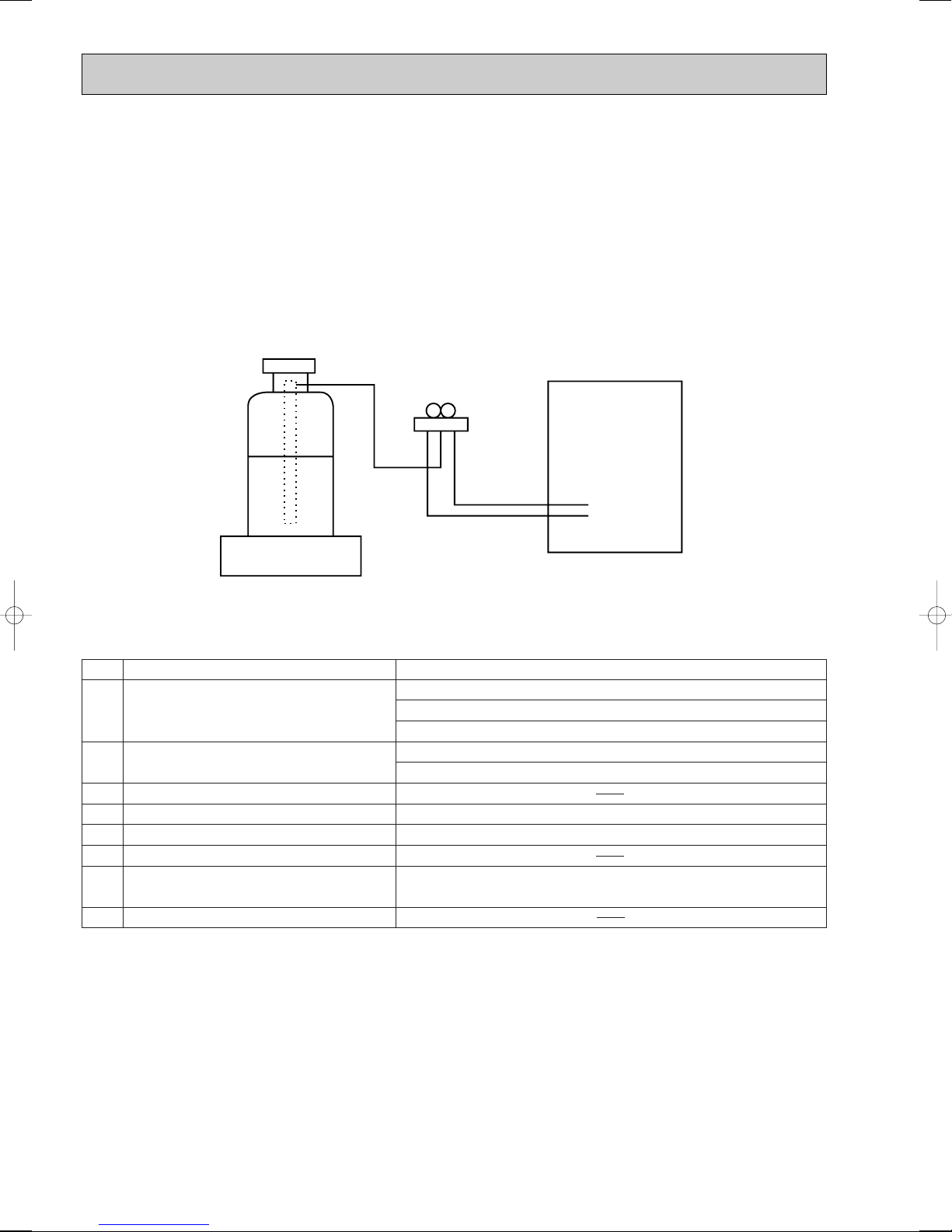
When charging directly from cylinder
· Check that cylinder for R410A on the market is syphon type.
· Charging should be performed with the cylinder of syphon stood vertically. (Refrigerant is charged from liquid phase.)
Unit
Gravimeter
[3] Service tools
(1) Use the below service tools as exclusive tools for R410A refrigerant.
No. Tool name Specifications
1 Gauge manifold ·Only for R410A
·Use the existing fitting
·Use high-tension side pressure of 5.3MPa·G or over.
2 Charge hose ·Only for R410A
·Use pressure performance of 5.09MPa·G or over.
3 Electronic scale
4 Gas leak detector ·Use the detector for R134a, R407C or R410A.
5 Adaptor for reverse flow check ·Attach on vacuum pump.
6 Refrigerant charge base
7 Refrigerant cylinder ·Only for R410A ·Top of cylinder (Pink)
·Cylinder with syphon
8 Refrigerant recovery equipment
specifications
. (UNF1/2)
4
(2) Cautions for refrigerant piping work
1/4
3/8
1/2
5/8
3/4
6.35
9.52
12.70
15.88
19.05
0.8
0.8
0.8
1.0
—
0.8
0.8
0.8
1.0
1.0
Nominal
dimensions(inch)
Diagram below: Piping diameter and thickness
Outside
diameter
(mm)
Thickness
(mm)
R410A R22
1/4
3/8
1/2
5/8
3/4
6.35
9.52
12.70
15.88
19.05
9.1
13.2
16.6
19.7
—
9.0
13.0
16.2
19.4
23.3
Nominal
dimensions(inch)
Flare cutting dimensions
Outside
diameter
Dimension A
( )
+0
-0.4
(mm)
R410A R22
1/4
3/8
1/2
5/8
3/4
6.35
9.52
12.70
15.88
19.05
17.0
22.0
26.0
29.0
—
17.0
22.0
24.0
27.0
36.0
Nominal
dimensions(inch)
Flare nut dimensions
Outside
diameter
Dimension B
(mm)
R410A R22
Gauge manifold
Charge hose
Gas leak detector
Refrigerant recovery equipment
Refrigerant cylinder
Applied oil
Safety charger
Charge valve
Vacuum pump
Flare tool
Bender
Pipe cutter
Welder and nitrogen gas cylinder
Refrigerant charging scale
Vacuum gauge or thermistor vacuum gauge and
vacuum valve
Charging cylinder
Air purge, refrigerant charge
and operation check
Gas leak check
Refrigerant recovery
Refrigerant charge
Apply to flared section
Prevent compressor malfunction
when charging refrigerant by
spraying liquid refrigerant
Prevent gas from blowing out
when detaching charge hose
Vacuum drying and air
purge
Flaring work of piping
Bend the pipes
Cut the pipes
Weld the pipes
Refrigerant charge
Check the degree of vacuum. (Vacuum
valve prevents back flow of oil and refrigerant to thermistor vacuum gauge)
Refrigerant charge
Tool exclusive for R410A
Tool exclusive for R410A
Tool for HFC refrigerant
Tool exclusive for R410A
Tool exclusive for R410A
Ester oil and alkylbenzene
oil (minimum amount)
Tool exclusive for R410A
Tool exclusive for R410A
Tools for other refrigerants can
be used if equipped with adopter for reverse flow check
Tools for other refrigerants
can be used by adjusting
flaring dimension
Tools for other refrigerants can be used
Tools for other refrigerants can be used
Tools for other refrigerants can be used
Tools for other refrigerants can be used
Tools for other refrigerants
can be used
Tool exclusive for R410A
Tools and materials Use R410A tools Can R22 tools be used?
(Usable if equipped
with adopter for rever se flow)
(Usable by adjusting
flaring dimension)
Can R407C tools be used?
Ester oil:
Alkylbenzene oil: minimum amount
(Usable if equipped
with adopter for rever se flow)
(Usable by adjusting
flaring dimension)
: Prepare a new tool. (Use the new tool as the tool exclusive for R410A.)
: Tools for other refrigerants can be used under certain conditions.
: Tools for other refrigerants can be used.
New refrigerant R410A is adopted for replacement inverter series. Although the refrigerant piping work for R410Ais same
as for R22, exclusive tools are necessary so as not to mix with different kind of refrigerant. Furthermore as the working
pressure of R410A is 1.6 time higher than that of R22, their sizes of flared sections and flare nuts are different.
1Thickness of pipes
Because the working pressure of R410A is higher compared to R22, be sure to use refrigerant piping with thickness
shown below. (Never use pipes of 0.7mm or below.)
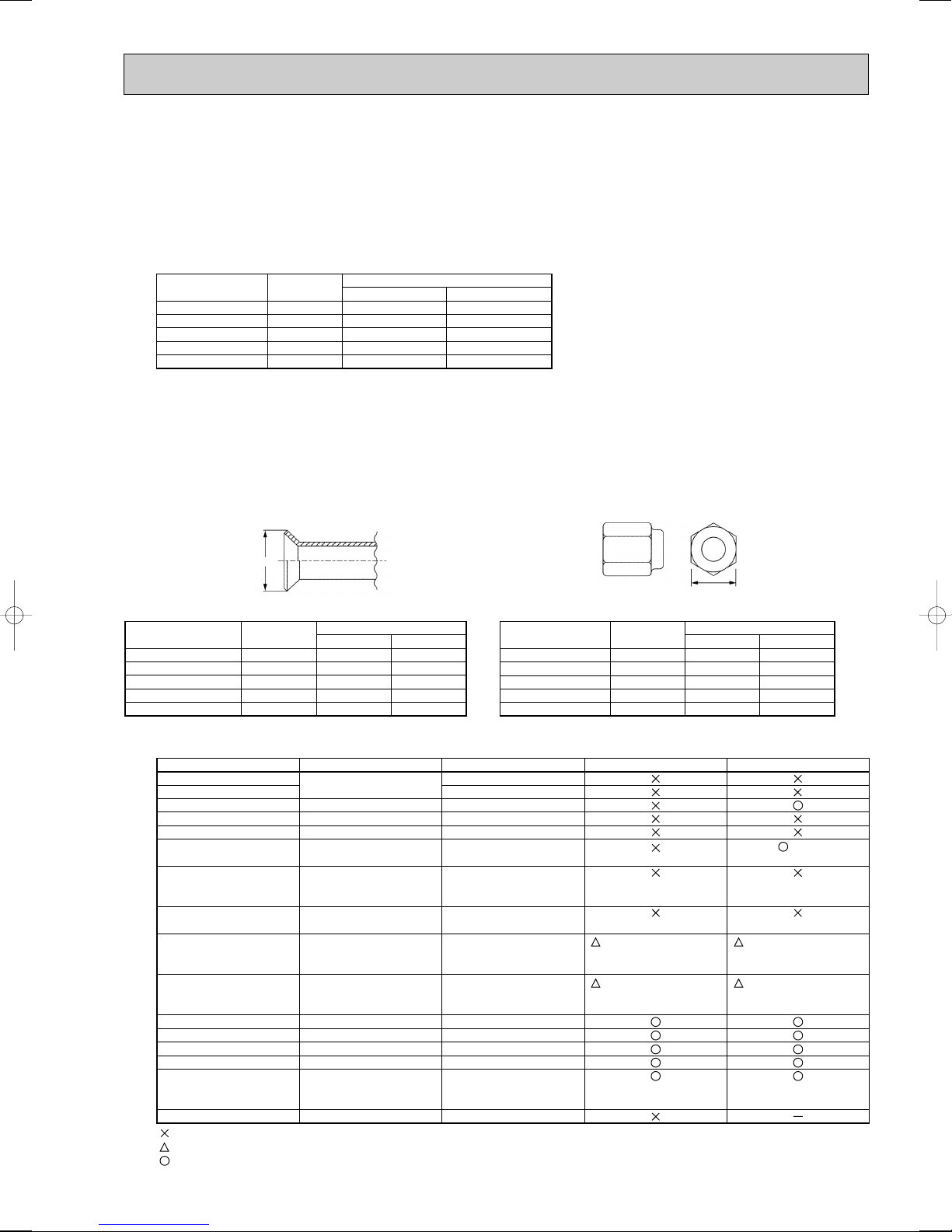
2Dimensions of flare cutting and flare nut
The component molecules in HFC refrigerant are smaller compared to conventional refrigerants. In addition to that,
R410A is a refrigerant, which has higher risk of leakage because of its working pressure higher than that of other refrigerants. Therefore, to enhance airtightness and intensity, flare cutting dimension of copper pipe for R410A have been specified separately from the dimensions for other refrigerants as shown below. The dimension B of flare nut for R410A also
have partly been changed to increase intensity as shown below. Set copper pipe correctly referring to copper pipe flaring
dimensions for R410A below. For 1/2” and 5/8”, the dimension B changes.
Use torque wrench corresponding to each dimension.
Dimension A
3Tools for R410A (The following table shows whether conventional tools can be used or not.)
5
Dimension B
3 OVERVIEW OF UNITS
5HP
Rated capacity (kW)
(Cooling/Heating)
14.0/16.0
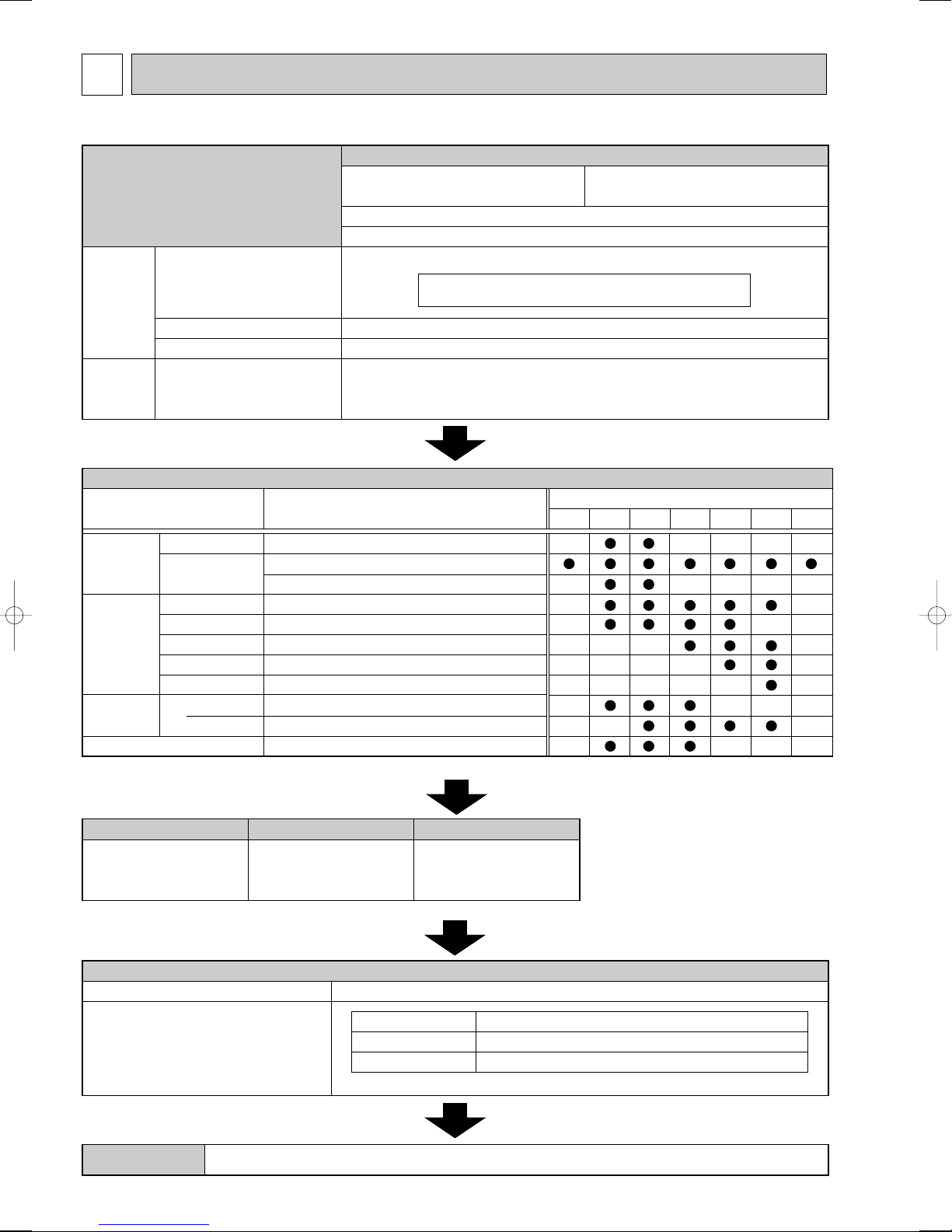
MXZ-8A140VA/ MXZ-8A140VA1/ MXZ-8A140VA2/ MXZ-8A140VA3
R410A
Indoor unit
that can be
connected
Branch box
that can be
connected
Capacity
Number of units
Total system wide capacity
Type 22 ~ Type 80
2 ~ 8 units
1 ~ 2 units
31 ~ 132 % of outdoor unit capacity (4.4 kW ~ 18.5 kW)
Number of units
Outdoor unit
Ceiling
concealed
4-way
ceiling cassette
Wall
mounted
Model type
Model name
deluxe
standard
Low static pressure
Low static pressure
High static pressure
High static pressure
High static pressure
2 by 2 type
standard
MSZ-FA25/35, FD25/35
MSZ-GA22/25/35/50/60/71/80, GB50, GC22/25/35
MSXZ-DB25/35
SEZ-KC25, KA35/50/60/71, KD25/35/50/60/71
MEXZ-GA25/35/50/60
PEAD-RP50/60/71EA.UK
PEAD-RP60/71GA.UK
PEA-RP71EA
SLZ-KA25/35/50
PLA-RP35/50/60/71BA(.UK)
MFZ-KA25/35/50
Floor standing
Capacity class
2.2kW 2.5kW 3.5kW 5.0kW 6.0kW 7.1kW 8.0kW
Connectable indoor unit lineup (Heat pump inverter type)
<NOTE> The lineup of a connectable indoor unit depends on a district/areas/country.
Branch box PAC-AK50BC
5 branches
(MAX. 5 units)
PAC-AK30BC
3 branches
(MAX. 3 units)
Number of branches
Indoor unit that
can be connected
( )
w Max. 2 branch boxes can be connected to 1 outdoor unit.
w According to the connection method, you can choose the favorite one.
2- branch pipe (joint) : Optional parts
In case of using 1- branch box
In case of using 2- branch boxes
No need
Model name Connection method
flare
brazing
MSDD-50AR-E
MSDD-50BR-E
Option
Optional accessories of indoor units and outdoor units are available.
CAUTION : The indoor unit which rated capability exceeds
8.0kW (80 type) can NOT be connected.
3-1. CONSTRUCTION OF SYSTEM
6
3-2. SYSTEM OUTLINE
MX Z - 8 A 140 V A
Model type
Power supply
V: Single phase 220/230/240V 50Hz
220V 60Hz
Multi type heat pump
inverter outdoor unit
Indicates equivalent to rated cooling capacity.
(O0.1kW)
Number of connectable indoor units (MAX.)
Control and refrigerant
A : New A control and R410A
PAC - A K 50 BC
(Indispensable)
Optional parts
Symbol of factory
Branch box (Controller)
Number of branches
50 : 5 branches
30 : 3 branches
Applicable refrigerant
A : R410A
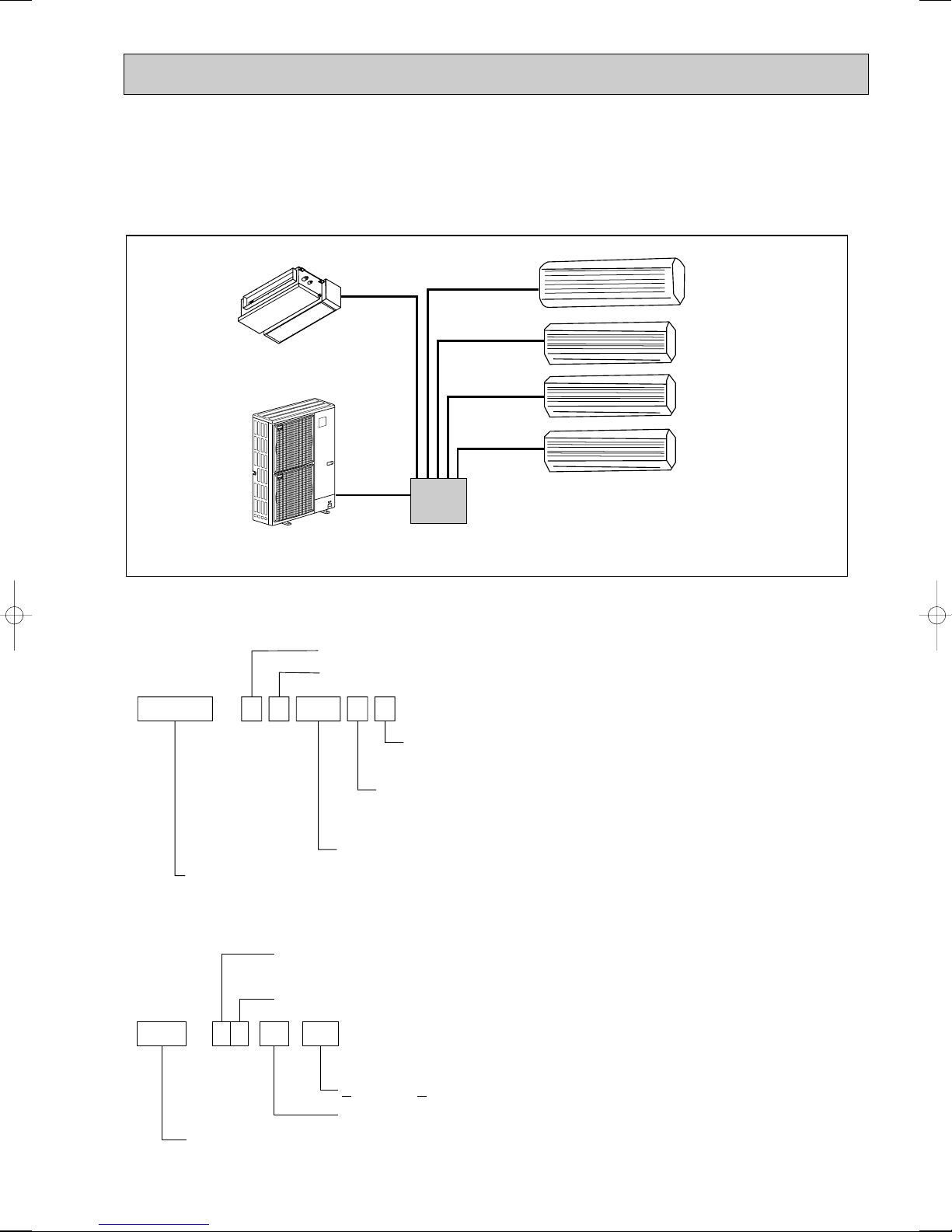
The additional connection of the Branch Box together with employment of the compact trunk-looking outdoor unit can successfully realizes a long distance piping for big houses. Equipped with a microcomputer, the Branch Box can translate the
transmission signal of indoor units to achieve the optimum control.
3-2-1. System example
Indoor unit (Ceiling concealed type)
Indoor unit
(Wall mounted type)
Outdoor unit
3-2-2. Method for identifying
■ Outdoor unit
■ Branch box
Branch Box
7
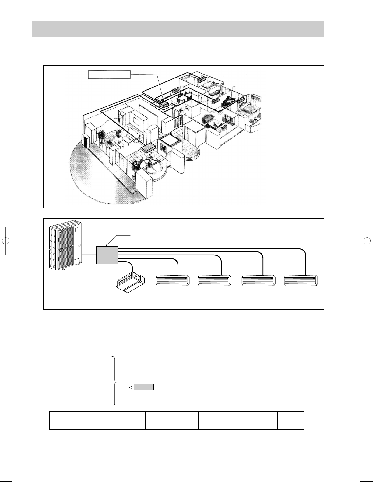
3-3. TYPICAL COMBINATION EXAMPLE
Branch box (5 branch type)
Outdoor unit
SEZ-60 MSZ-35 MSZ-35 MSZ-25 MSZ-25
Living
Dining Bedroom (1) Bedroom (2)
Master
bedroom
Total rated capacity
18.0 18.5kW
MSZ-25
=2.5
+
+
+
+
SEZ-60 = 6.0
MSZ-35 = 3.5
MSZ-35 = 3.5
MSZ-25 = 2.5
Branch box is located INSIDE of condominium
Branch box
(Inside)
■ System example of 5 indoor units
Installing branch box indoors
Only 1 piping is required between the outdoor and
indoor offering a fine external view.
■ Verification
The rated capacity should be determined by observing the table below. The unit’s quantities are limited in 2 to 8 units.
For the next step, make sure that the selected total rated capacity is in a range of 4.4 ~ 18.5kW.
The total indoor unit capacity should be within the outdoor units. (=14.0kW is preferred).
Combination of excessive indoor units and an outdoor unit may reduce the capacity of each indoor unit.
The rated indoor capacity is as the table below.
Example:
Indoor unit type (capacity class)
Rated capacity (cooling) (kW)
22
2.2
25
2.5
35
3.5
50
5.0
60
6.0
8
71
7.1
80
8.0
3-4. INSTALLATION
B
A
3-4-1. Outdoor unit installation location
For best performance, select proper position.
● Avoid places where combustible gas may be generated or leak.
● Avoid direct sunlight or other sources of heat.
● Install sunshade to protect the outdoor unit if direct sunlight hits the unit.
● Install the outdoor unit with enough distance between neighbours as operation noise may disturb the neighbours.
● Avoid the position that the unit is covered by snow or snow blows directly against the air outlet. The snow block or blow
will reduce the airflow of the outdoor unit.
In the areas of heavy snow, special countermeasures must be taken at installation to protect the outdoor unit from
malfunction caused by snow.
● Select a location permitting easy wiring and pipe access to the power source and indoor unit.
● Drain water must be drained freely during operation. Check for draining.
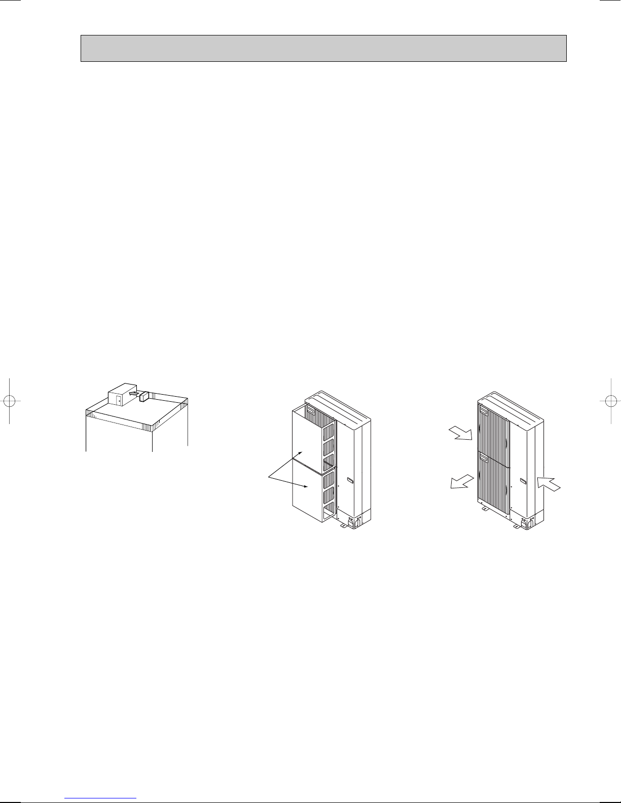
3-4-2. Ventilation and service space
(1)Windy location installation
When installing the outdoor unit on a rooftop or other location unprotected from the wind, situate the air outlet of the unit so
that it is not directly exposed to strong winds. Strong wind entering the air outlet may impede the normal airflow and a
malfunction may result.
The following shows 3 examples of precautions against strong winds.
● Face the air outlet towards the nearest available wall about 50 cm away from the wall. (Fig. 2-1)
● Install an optional air guide if the unit is installed in a location where strong winds from a typhoon, etc. may directly enter
the air outlet. (Fig. 2-2)
AAir guide
● Position the unit so that the air outlet blows perpendicularly to the seasonal wind direction, if possible. (Fig. 2-3)
BWind direction
Fig.2-1
Fig.2-2 Fig.2-3
9
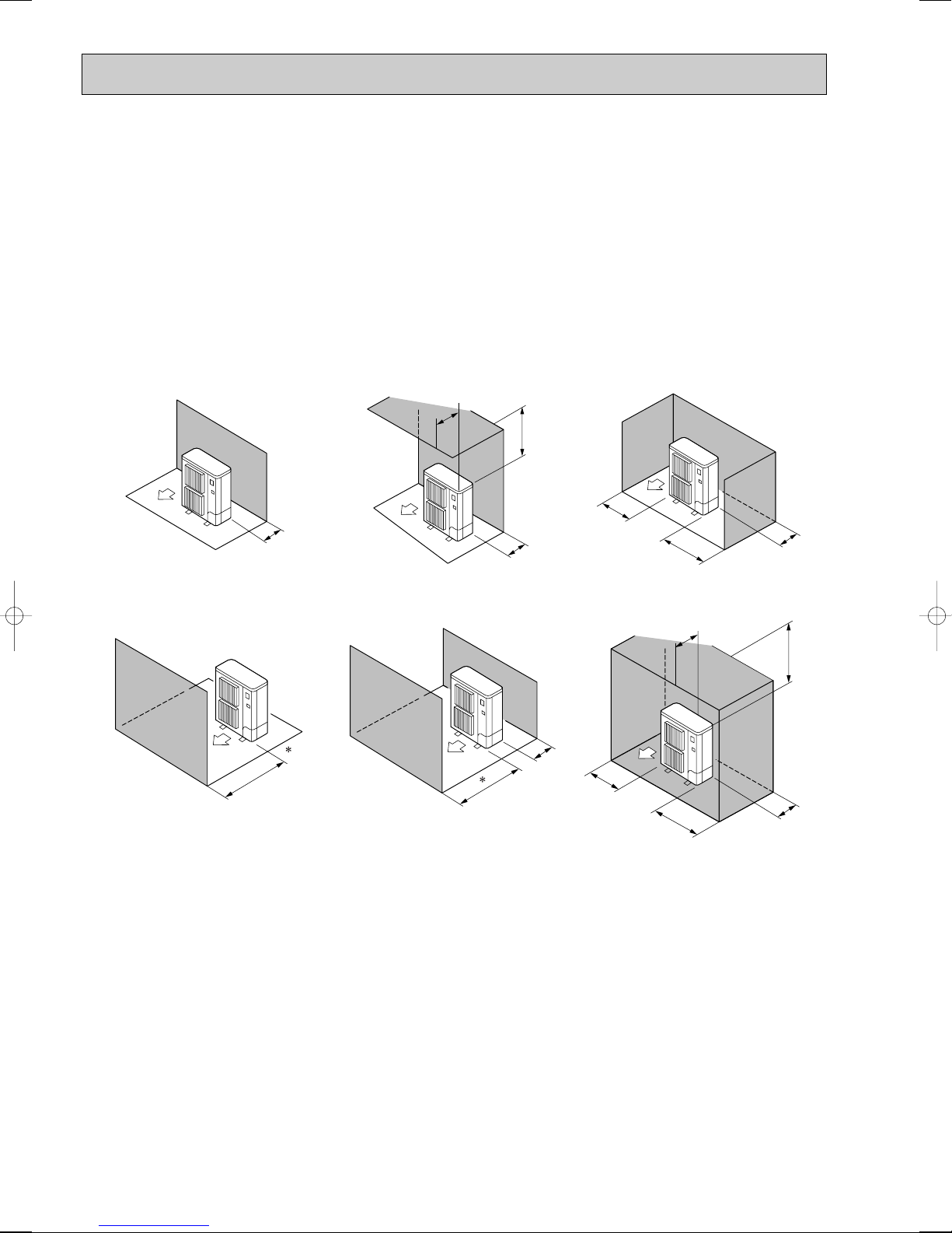
(2) When installing a single outdoor unit
150
300
1000
Max. 500
150
1000
250
250
1500
500
Max. 500
1000
200
300
200
Minimum dimensions are as follows, except for Max., meaning Maximum dimensions, indicated.
Refer to the figures for each case.
● Obstacles at rear only (Fig. 2-4)
● Obstacles at rear and above only (Fig. 2-5)
· Do not install the optional air outlet guides for upward airflow.
● Obstacles at rear and sides only (Fig. 2-6)
● Obstacles at front only (Fig. 2-7)
w When using an optional air outlet guide, the clearance is 500 mm or more.
● Obstacles at front and rear only (Fig. 2-8)
w When using an optional air outlet guide, the clearance is 500 mm or more.
● Obstacles at rear, sides, and above only (Fig. 2-9)
· Do not install the optional air outlet guides for upward airflow.
unit : mm
Fig.2-4
Fig.2-5 Fig.2-6
Fig.2-8Fig.2-7
Fig.2-9
10
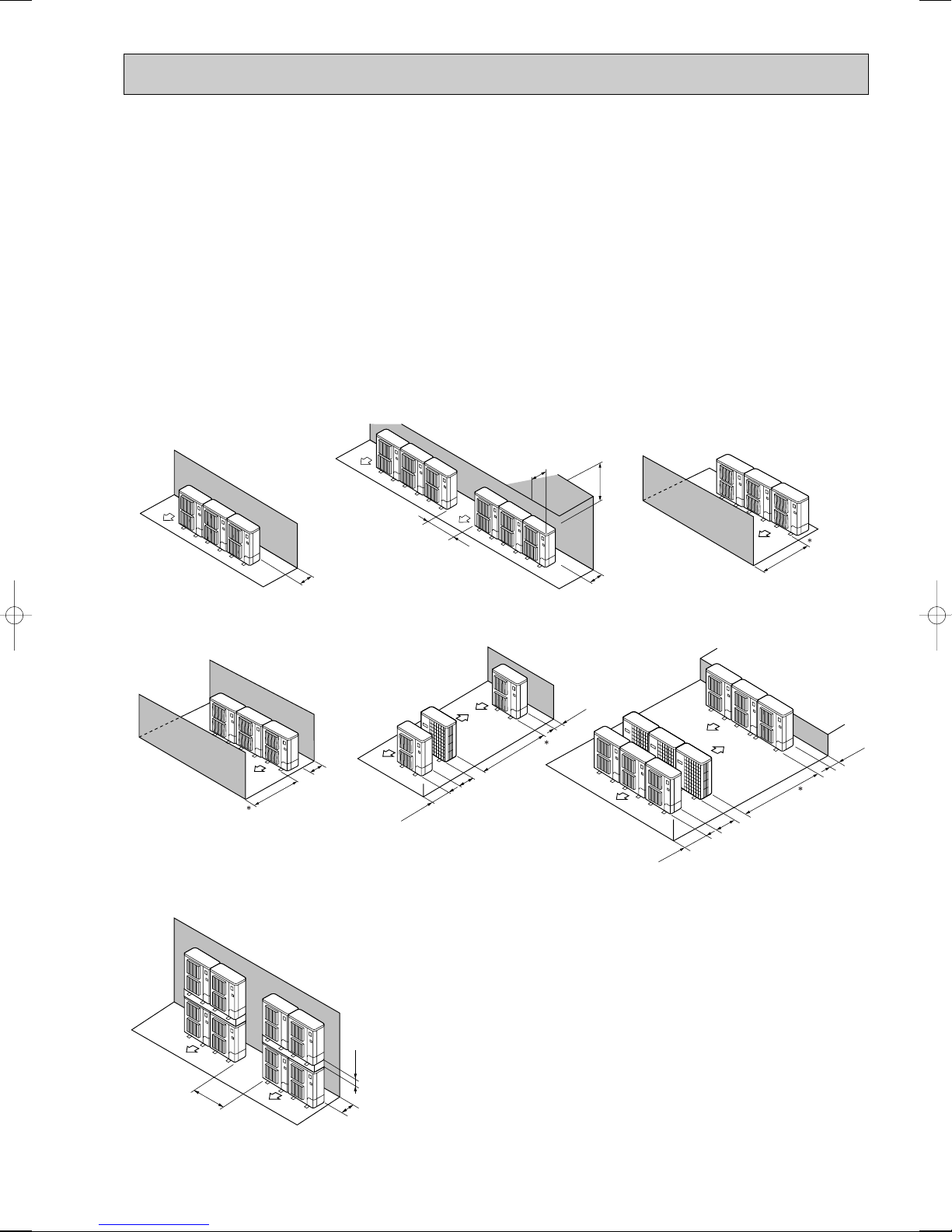
(3) When installing multiple outdoor units
300
1500
500
1500
M
ax. 300
1000
600
2000
150
1500
500
1500
1500
800
150
1500
600
3000
500
Leave 10 mm space or more between the units.
● Obstacles at rear only (Fig. 2-10)
● Obstacles at rear and above only (Fig. 2-11)
• No more than 3 units must be installed side by side. In addition, leave space as shown.
• Do not install the optional air outlet guides for upward airflow.
● Obstacles at front only (Fig. 2-12)
w When using an optional air outlet guide, the clearance is 1000 mm or more.
● Obstacles at front and rear only (Fig. 2-13)
w When using an optional air outlet guide, the clearance is 500 mm or more.
● Single parallel unit arrangement (Fig. 2-14)
w When using an optional air outlet guide installed for upward airflow, the clearance is 1000 mm or more.
● Multiple parallel unit arrangement (Fig. 2-15)
w When using an optional air outlet guide installed for upward airflow, the clearance is 1500 mm or more.
● Stacked unit arrangement (Fig. 2-16)
• The units can be stacked up to 2 units high.
• No more than 2 stacked units must be installed side by side. In addition, leave space as shown.
unit : mm
Fig.2-12Fig.2-11Fig.2-10
Fig.2-14Fig.2-13
Fig.2-15
Fig.2-16
11
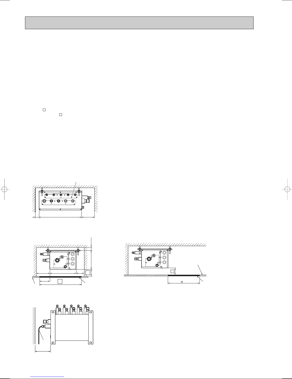
3-4-3. Space required for Installation and servicing for Branch box.
B
A
450
Min. 250
Min.
50
(1)
G
H
(3)
Min. 250
450
E
F
D
A
280
Min.
250
w 1
Min.
250
198 Min. 30
180-200
w3
w2
E
C
D
B
A
(2)
(1) Front View (Fig. 3-1)
A Branch box
B On the side of piping
(2)Side View (Fig. 3-2, Fig. 3-3)
C For indoor installations
D Ceiling board
E Maintenance hole
F PCB side
w1:A minimum 350 mm is required for 90° bends in refrigerant piping.
w2:AAis “Min. 200 mm”.
(Premise: The slope of drain piping is securable 1/100 or more. Required 200 mm or more, when not securable.)
In the case of less than 200 mm (for example A is 100 mm), the exchange work of Branch box from a maintenance hole
becomes difficult (Only exchange work of a PCB, linear expansion valve coils, sensors and drain pan is possible).
w3:BBis “ 600”.
In the case of “ 450”, prepare a maintenance hole at a PCB side as it is shown in Fig. 3-3, and
“Min. 300 mm” is needed as distance A.
In the case of less than 300 mm (for example A is 100 mm), the exchange work of Branch box, linear expansion
valve coils, sensors, and drain pan from a maintenance hole becomes difficult. Only exchange work of a PCB is possible.
(3) Top View (Fig. 3-4)
G Refrigerant piping
H When facing in the opposite direction to the refrigerant piping.
NOTE1: The branch box is only for indoor use.
NOTE2: Please attach the special optional cover (PAC-AK350CVR-E) to install branch box in the outdoors.
Fig.3-1
unit : mm
Fig.3-3Fig.3-2
Fig.3-4
12
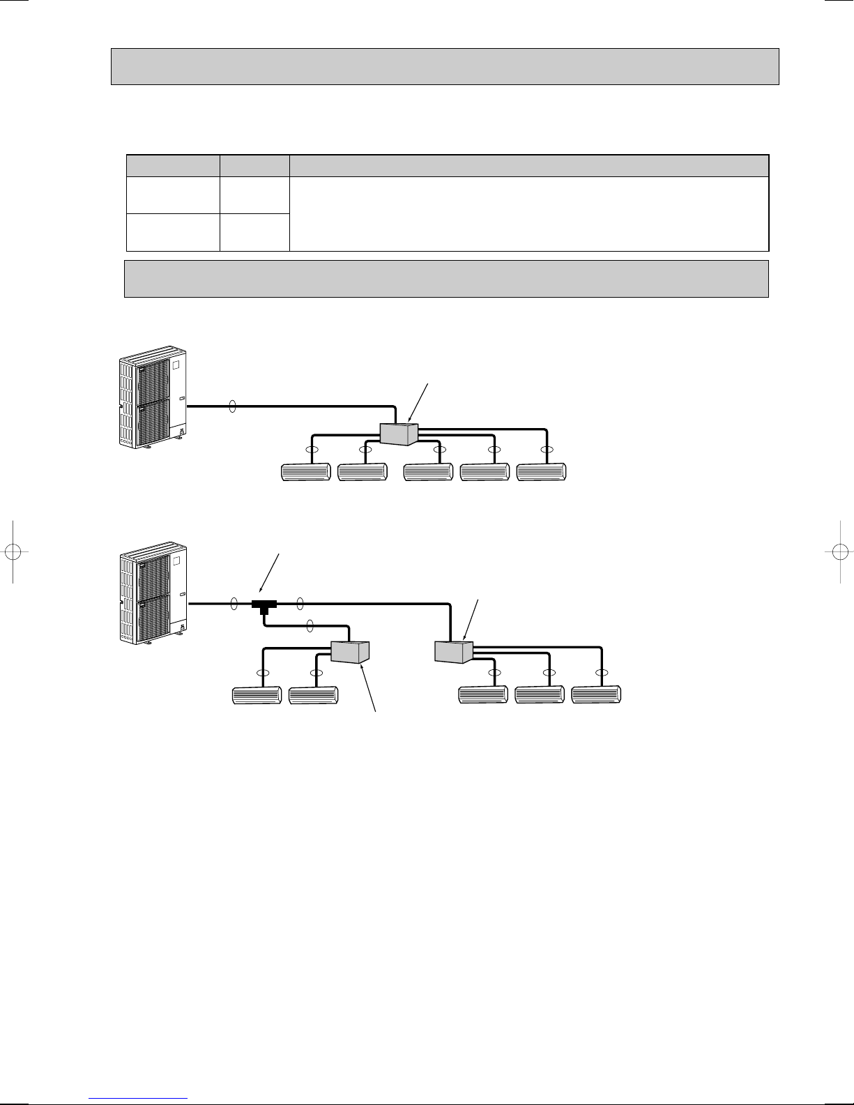
3-5. SIMPLIFIED PIPING SYSTEM
Liquid (mm)
Gas (mm)
{9.52
{15.88
The piping connection size differs according to the type and capacity of indoor units.
Match the piping connection size of branch box with indoor unit.
If the piping connection size of branch box does not match the piping connection size of
indoor unit, use optional different-diameter (deformed) joints to the branch box side.
(Connect deformed joint directly to the branch box side.)
AB
A
A
A
BB
BBB
2 branches pipe (joint)
: optional parts
Branch box #1
Branch box #2
Piping connection size
Flare connection employed. (No brazing!)
■ In case of using 1-branch box
Flare connection employed (No. brazing)
A
■ In case of using 2-branch boxes
Branch box
BB BBB
■ Installation procedure (2 branch pipe (joint))
Refer to the installation manuals of MSDD-50AR-E and MSDD-50BR-E.
13

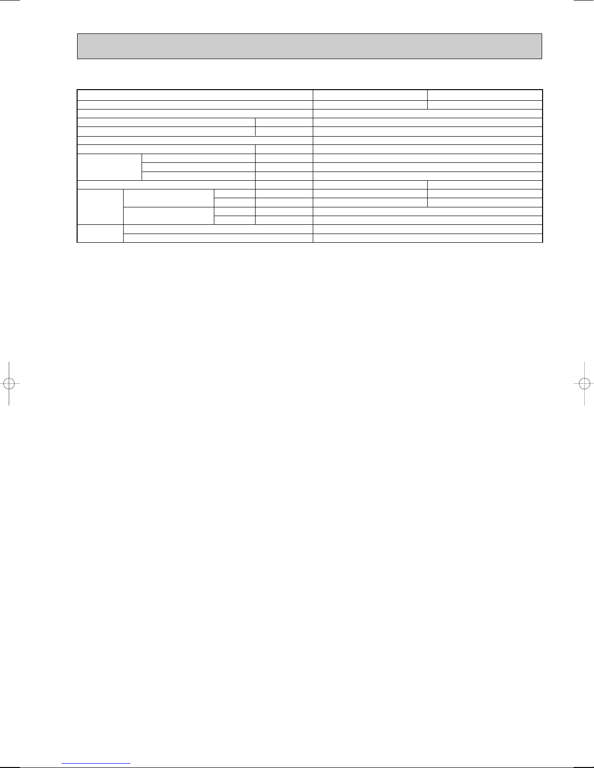
4 SPECIFICATIONS
• Outdoor unit : MXZ-8A140VA MXZ-8A140VA1
MXZ-8A140VA2 MXZ-8A140VA3
Service Ref.
Rated Cooling capacity
Rated power consumption w1
Operating current w1
Operating power factor w1
Cooling
Starting current (Outdoor unit)
Rated Heating capacity
Rated power consumption w1
Operating current w1
Operating power factor w1
Heating
Standard performance
Breaker
Max. current (Outdoor unit only)
Power supply (phase, cycle, voltage)
External finish
Refrigerant control
Compressor
Crankcase heater
Heat exchanger
Fan Fan (drive) o No.
Defrost method
Noise level
OUTDOOR UNIT
Dimensions
Weight
Refrigerant
Pipe size O.D.
Connection method
REFRIGERANT PIPING
w1 In case of connecting 3 indoor units (6.0kW class), electrical data is only for outdoor unit.
Conversion formula
[6.35mm
1/4 inch
Notes1.Rating Conditions (ISO T1)
3. Guaranteed voltage
198~264V, 50Hz 198~242V, 60Hz
Starting current (Outdoor unit)
Model
Motor output
Starter type
Protection devices
Fan motor output
Airflow
Cooling
Heating
W
D
H
Charge
Oil (Model)
[9.52mm
3/8 inch
Cooling :Indoor : D.B. 27˚C (80˚F), W.B. 19˚C (66˚F) Outdoor : D.B. 35˚C (95˚F), W.B. 24˚C (75˚F)
Heating :Indoor : D.B. 20˚C (68˚F) Outdoor : D.B. 7˚C (45˚F), W.B. 6˚C (43˚F)
Refrigerant piping length (one way) : Main Piping (From outdoor unit to branch box) : 5m
2. Guaranteed operating range
Cooling
Heating
Upper limit
Lower limit
Upper limit
Lower limit
Liquid
Gas
Indoor side
Outdoor side
[12.7mm
1/2 inch
[15.88mm
P-series
D.B. 35˚C, W.B. 22.5˚C
D.B. 19˚C, W.B. 15˚C
D.B. 28˚C
D.B. 17˚C
kW
kW
A
%
A
kW
kW
A
%
A
A
kW
W
kW
/min (CFM
K
dB
dB
mm (in.)
mm (in.)
mm (in.)
kg (lbs)
kg (lbs)
L
mm
mm
5/8 inch
Branch Piping (From branch box to each indoor units) : each 3m
Indoor
MXZ-8A140VA/ MXZ-8A140VA1/ MXZ-8A140VA2/ MXZ-8A140VA3
17.30/16.55/15.86, 17.30
17.82/17.05/16.33, 17.82
Please refer to "10.ELECTRICAL WIRING".
Single, 50Hz, 220/230/240V, Single, 60Hz, 220V
Linear Expansion Valve (In branch box)
HP switch, LP switch, Discharge thermo
)
[19.05mm
3/4 inch
M-series, S-series
D.B. 32˚C, W.B. 23˚C
D.B. 21˚C, W.B. 15˚C
D.B. 27˚C
D.B. 20˚C
Outdoor
D.B. 46˚C
D.B. –5˚C
D.B. 21˚C, W.B. 15˚C
D.B. –15˚C, W.B. –15˚C
Conversion formula:
14.0
3.79
99.6
14
16.0
3.90
99.5
14
29.5
Munsell 3Y 7.8/1.1
Hermetic
ANB33FDCMT
2.9
Line start
—
Plate fin coil
Propeller fan o 2
0.060 +0.060
100 (3,530)
Reverse cycle
50
52
950 (37-3/8)
330+30 (13+1-3/16)
1,350 (53-1/8)
128 (282)
R410A
8.5 (18.7), 40m
2.3 (MEL56)
[9.52
[15.88
Flared
Flared
kcal/h = kW o 860
Btu/h = kW o 3412
CFM = m3/min o 35.31
4. Above data are based on the indicated voltage.
Single, 50Hz, 220/230/240V, Single, 60Hz, 220V
5. Refer to the service manual of indoor unit for the indoor unit's specifications.
14
• Branch box : PAC-AK50BC PAC-AK30BC
Model name
Connectable number of indoor units
Power supply (from outdoor unit)
Input
Running current
External finish
Drain hose size (on site)
Dimensions
Weight
Piping
connection
(Flare)
Wiring
Width
Depth
Height
Branch (indoor side)
Main (outdoor side)
To indoor unit
To outdoor unit
W
Liquid
Gas
Liquid
Gas
kW
A
mm
mm
mm
mm
kg
mm
mm
mm
mm
[9.52 O 4 {A,B,C,D}, [12.7 o 1{E}
W The piping connection size differs according to the type and capacity of indoor units. Match the piping connection size for
indoor and branch box. If the piping connection size of branch box does not match the piping connection size of indoor units,
use optional different-diameter (deformed) joints to the branch box side. (Connect deformed joint directly to the branch box
side.)
PAC-AK50BC PAC-AK30BC
MAX. 5
Single phase, 220/230/240V, 50Hz, Single phase, 220V, 60Hz
0.003
0.05
Galvanized sheets
O.D.20 (VP-16)
450
280
198
9.3
[6.35 O 5 {A,B,C,D,E}
[9.52
[15.88
Each 3-wire, plus earth wire
3-wire, plus earth wire
MAX. 3
8.1
[6.35 O 3 {A,B,C}
[9.52 O 3 {A,B,C}
15
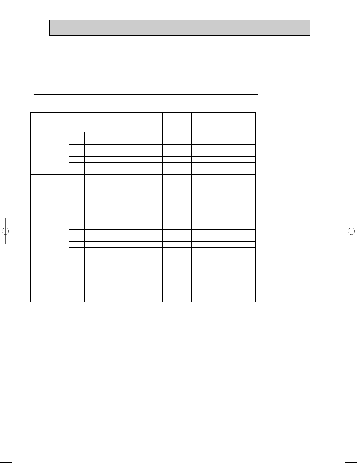
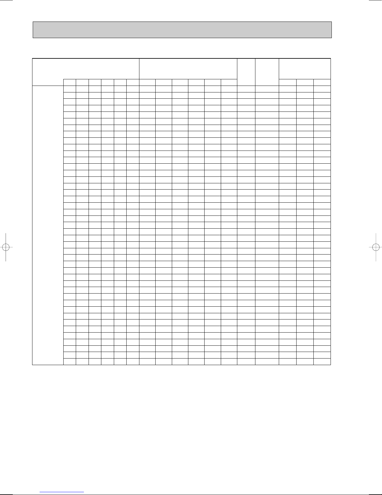
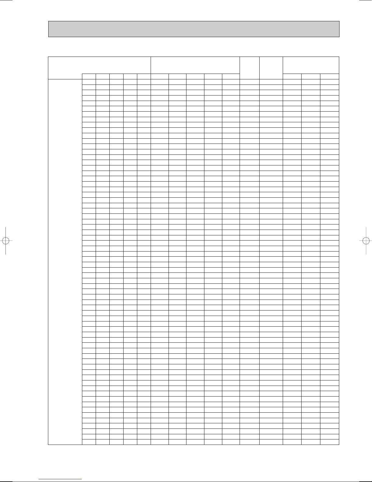
5 DATA
1
22 – 2200 – 2200 1050 4.6 4.4 4.8
25 – 2500 – 2500 1140 5.0 4.8 5.2
35 – 3500 – 3500 1410 6.2 5.9 6.5
50 – 5000 – 5000 1700 7.5 7.2 7.8
60 – 6000 – 6000 2000 8.8 8.4 9.2
71 – 7100 – 7100 2310 10.1 9.7 10.6
2
22 22 2200 2200 4400 1590 7.0 6.7 7.3
22 25 2200 2500 4700 1650 7.2 6.9 7.6
22 35 2200 3500 5700 1910 8.4 8.0 8.8
22 50 2200 5000 7200 2340 10.3 9.8 10.7
22 60 2200 6000 8200 2620 11.5 11.0 12.0
22 71 2200 7100 9300 2910 12.8 12.2 13.4
25 25 2500 2500 5000 1700 7.5 7.2 7.8
25 35 2500 3500 6000 2000 8.8 8.4 9.2
25 50 2500 5000 7500 2430 10.7 10.2 11.2
25 60 2500 6000 8500 2700 11.9 11.4 12.4
25 71 2500 7100 9600 2990 13.1 12.6 13.7
35 35 3500 3500 7000 2290 10.1 9.6 10.5
35 50 3500 5000 8500 2700 11.9 11.4 12.4
35 60 3500 6000 9500 2960 13.0 12.5 13.6
35 71 3500 7100 10600 3370 14.8 14.2 15.5
50 50 5000 5000 10000 3090 13.6 13.0 14.2
50 60 5000 6000 11000 3560 15.6 15.0 16.3
50 71 5000 7100 12100 4140 18.2 17.4 19.0
60 60 6000 6000 12000 4080 17.9 17.2 18.7
60 71 6000 7100 13100 4720 20.7 19.9 21.7
71 71 7000 7000 14000 5220 22.9 22.0 24.0
Number of operated indoor unit
Capacity of each
unit (W
)
Total
rated
capacity
(W)
Outdoor unit
input (W
)
Outdoor unit current (A
)
Unit A Unit B Unit A Unit B
230V 240V 220V
5-1. CAPACITY AND CHARACTERISTICS
Note:
• Cooling capacity is based on D.B. 27: / W.B. 19.0: (indoor temperature), D.B. 35: (outdoor temperature).
• Heating capacity is based on D.B. 20: (indoor temperature), D.B. 7: / W.B. 6: (outdoor temperature).
The rated capacities below show the rise in the indoor unit connection capacity when operating frequency is constant.
Values for changes in capacity are fixed after accounting for variations in operating frequency and should be used as
reference values.
• Please refer not to the table below but to ”10. ELECTRICAL
(1) Cooling mode
<Cooling>
WIRING” for the breaker selection.
16
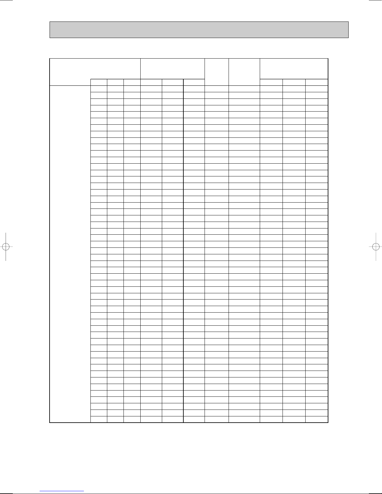
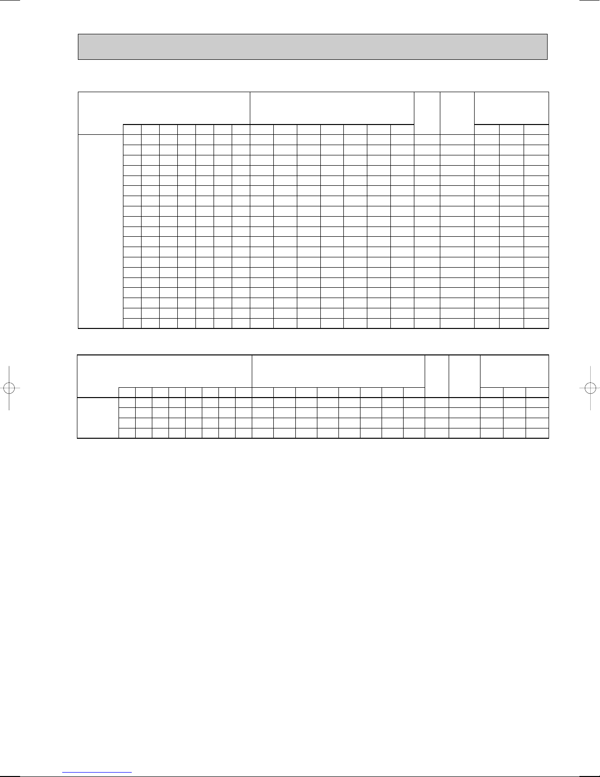
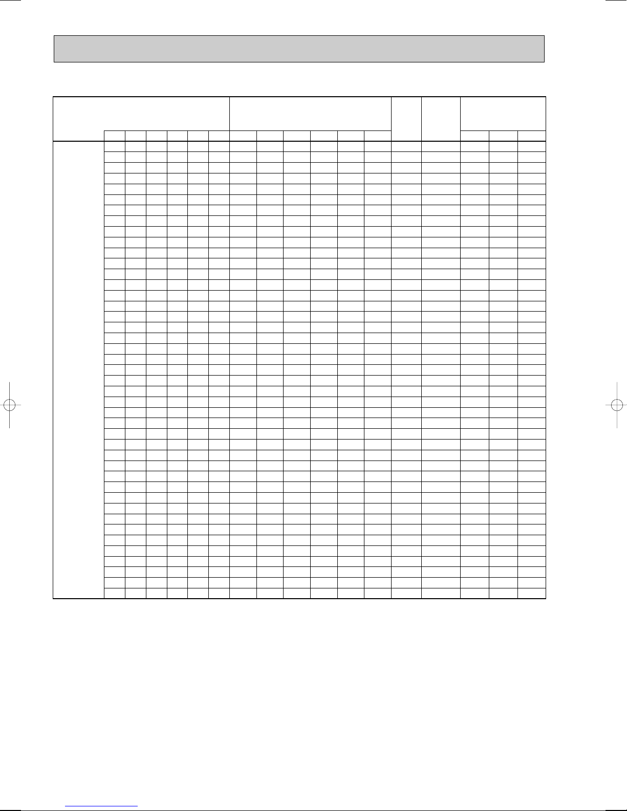
<Cooling>
Number of operated indoor unit
Unit A Unit B Unit C Unit A Unit B Unit C
22 22 22 2200 2200 2200 6600 2170 9.5 9.1 10.0
22 22 25 2200 2200 2500 6900 2260 9.9 9.5 10.4
22 22 35 2200 2200 3500 7900 2540 11.2 10.7 11.7
22 22 50 2200 2200 5000 9400 2940 12.9 12.4 13.5
22 22 60 2200 2200 6000 10400 3270 14.4 13.8 15.0
22 22 71 2200 2200 7100 11500 3810 16.7 16.0 17.5
22 25 25 2200 2500 2500 7200 2340 10.3 9.8 10.7
22 25 35 2200 2500 3500 8200 2620 11.5 11.0 12.0
22 25 50 2200 2500 5000 9700 3010 13.2 12.7 13.8
22 25 60 2200 2500 6000 10700 3410 15.0 14.4 15.7
22 25 71 2200 2500 7100 11800 3970 17.4 16.7 18.2
22 35 35 2200 3500 3500 9200 2880 12.6 12.1 13.2
22 35 50 2200 3500 5000 10700 3410 15.0 14.4 15.7
22 35 60 2200 3500 6000 11700 3920 17.2 16.5 18.0
22 35 71 2200 3500 7100 12800 4540 19.9 19.1 20.8
22 50 50 2200 5000 5000 12200 4190 18.4 17.6 19.2
22 50 60 2200 5000 6000 13200 4780 21.0 20.1 21.9
22 50 71 2150 4900 6950 14000 5220 22.9 22.0 24.0
22 60 60 2170 5920 5920 14000 5220 22.9 22.0 24.0
22 60 71 2010 5490 6500 14000 5040 22.1 21.2 23.1
22 71 71 1880 6060 6060 14000 4450 19.5 18.7 20.4
25 25 25 2500 2500 2500 7500 2430 10.7 10.2 11.2
25 25 35 2500 2500 3500 8500 2700 11.9 11.4 12.4
25 25 50 2500 2500 5000 10000 3090 13.6 13.0 14.2
25 25 60 2500 2500 6000 11000 3560 15.6 15.0 16.3
3
25 25 71 2500 2500 7100 12100 4140 18.2 17.4 19.0
25 35 35 2500 3500 3500 9500 2960 13.0 12.5 13.6
25 35 50 2500 3500 5000 11000 3560 15.6 15.0 16.3
25 35 60 2500 3500 6000 12000 4080 17.9 17.2 18.7
25 35 71 2500 3500 7100 13100 4720 20.7 19.9 21.7
25 50 50 2500 5000 5000 12500 4360 19.1 18.4 20.0
25 50 60 2500 5000 6000 13500 4970 21.8 20.9 22.8
25 50 71 2400 4790 6810 14000 5220 22.9 22.0 24.0
25 60 60 2410 5790 5790 14000 5220 22.9 22.0 24.0
25 60 71 2240 5380 6370 14000 4870 21.4 20.5 22.4
25 71 71 2100 5950 5950 14000 4310 18.9 18.1 19.8
35 35 35 3500 3500 3500 10500 3320 14.6 14.0 15.2
35 35 50 3500 3500 5000 12000 4080 17.9 17.2 18.7
35 35 60 3500 3500 6000 13000 4660 20.5 19.6 21.4
35 35 71 3480 3480 7050 14000 5220 22.9 22.0 24.0
35 50 50 3500 5000 5000 13500 4970 21.8 20.9 22.8
35 50 60 3380 4830 5790 14000 5220 22.9 22.0 24.0
35 50 71 3140 4490 6370 14000 4870 21.4 20.5 22.4
35 60 60 3160 5420 5420 14000 4920 21.6 20.7 22.6
35 60 71 2950 5060 5990 14000 4350 19.1 18.3 20.0
35 71 71 2770 5620 5620 14000 3900 17.1 16.4 17.9
50 50 50 4670 4670 4670 14000 5240 23.0 22.1 24.1
50 50 60 4380 4380 5250 14000 4650 20.4 19.6 21.3
50 50 71 4090 4090 5810 14000 4140 18.2 17.4 19.0
50 60 60 4120 4940 4940 14000 4180 18.4 17.6 19.2
50 60 71 3870 4640 5490 14000 3760 16.5 15.8 17.3
60 60 60 4670 4670 4670 14000 3790 16.6 15.9 17.3
Capacity of each unit (W
)
capacity
Total
rated
(W)
Outdoor unit
input (W
)
Outdoor unit current (A
230V 240V 220V
)
17
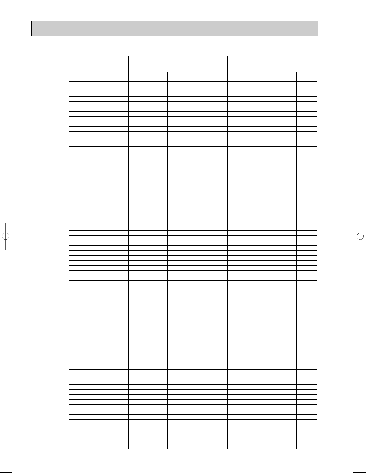
<Cooling>
Number of operated indoor unit
4
Total
Capacity of each unit (W
Unit A Unit B Unit C Unit D Unit A Unit B Unit C Unit D
22 22 22 22 2200 2200 2200 2200 8800 2780 12.2 11.7 12.8
22 22 22 25 2200 2200 2200 2500 9100 2860 12.6 12.0 13.1
22 22 22 35 2200 2200 2200 3500 10100 3130 13.7 13.2 14.4
22 22 22 50 2200 2200 2200 5000 11600 3870 17.0 16.3 17.8
22 22 22 60 2200 2200 2200 6000 12600 4420 19.4 18.6 20.3
22 22 22 71 2200 2200 2200 7100 13700 5100 22.4 21.5 23.4
22 22 25 25 2200 2200 2500 2500 9400 2940 12.9 12.4 13.5
22 22 25 35 2200 2200 2500 3500 10400 3270 14.4 13.8 15.0
22 22 25 50 2200 2200 2500 5000 11900 4030 17.7 17.0 18.5
22 22 25 60 2200 2200 2500 6000 12900 4600 20.2 19.4 21.1
22 22 25 71 2200 2200 2500 7100 14000 5220 22.9 22.0 24.0
22 22 35 35 2200 2200 3500 3500 11400 3760 16.5 15.8 17.3
22 22 35 50 2200 2200 3500 5000 12900 4600 20.2 19.4 21.1
22 22 35 60 2200 2200 3500 6000 13900 5230 23.0 22.0 24.0
22 22 35 71 2050 2050 3270 6630 14000 5240 23.0 22.1 24.1
22 22 50 50 2140 2140 4860 4860 14000 5220 22.9 22.0 24.0
22 22 50 60 2000 2000 4550 5450 14000 4980 21.9 21.0 22.9
22 22 50 71 1870 1870 4240 6020 14000 4400 19.3 18.5 20.2
22 22 60 60 1880 1880 5120 5120 14000 4450 19.5 18.7 20.4
22 22 60 71 1760 1760 4800 5680 14000 3980 17.5 16.8 18.3
22 25 25 25 2200 2500 2500 2500 9700 3010 13.2 12.7 13.8
22 25 25 35 2200 2500 2500 3500 10700 3410 15.0 14.4 15.7
22 25 25 50 2200 2500 2500 5000 12200 4190 18.4 17.6 19.2
22 25 25 60 2200 2500 2500 6000 13200 4780 21.0 20.1 21.9
22 25 25 71 2150 2450 2450 6950 14000 5220 22.9 22.0 24.0
22 25 35 35 2200 2500 3500 3500 11700 3920 17.2 16.5 18.0
22 25 35 50 2200 2500 3500 5000 13200 4780 21.0 20.1 21.9
22 25 35 60 2170 2460 3450 5920 14000 5220 22.9 22.0 24.0
22 25 35 71 2010 2290 3200 6500 14000 5040 22.1 21.2 23.1
22 25 50 50 2100 2380 4760 4760 14000 5220 22.9 22.0 24.0
22 25 50 60 1960 2230 4460 5350 14000 4810 21.1 20.2 22.1
22 25 50 71 1830 2080 4170 5920 14000 4260 18.7 17.9 19.6
22 25 60 60 1840 2100 5030 5030 14000 4310 18.9 18.1 19.8
22 25 60 71 1730 1970 4720 5580 14000 3860 17.0 16.2 17.7
22 35 35 35 2200 3500 3500 3500 12700 4480 19.7 18.9 20.6
22 35 35 50 2170 3450 3450 4930 14000 5220 22.9 22.0 24.0
22 35 35 60 2030 3220 3220 5530 14000 5110 22.4 21.5 23.5
22 35 35 71 1890 3010 3010 6090 14000 4500 19.8 18.9 20.7
22 35 50 50 1960 3120 4460 4460 14000 4810 21.1 20.2 22.1
22 35 50 60 1840 2930 4190 5030 14000 4310 18.9 18.1 19.8
22 35 50 71 1730 2750 3930 5580 14000 3860 17.0 16.2 17.7
22 35 60 60 1730 2770 4750 4750 14000 3900 17.1 16.4 17.9
22 50 50 50 1790 4070 4070 4070 14000 4090 18.0 17.2 18.8
22 50 50 60 1690 3850 3850 4610 14000 3730 16.4 15.7 17.1
25 25 25 25 2500 2500 2500 2500 10000 3090 13.6 13.0 14.2
25 25 25 35 2500 2500 2500 3500 11000 3560 15.6 15.0 16.3
25 25 25 50 2500 2500 2500 5000 12500 4360 19.1 18.4 20.0
25 25 25 60 2500 2500 2500 6000 13500 4970 21.8 20.9 22.8
25 25 25 71 2400 2400 2400 6800 14000 5220 22.9 22.0 24.0
25 25 35 35 2500 2500 3500 3500 12000 4080 17.9 17.2 18.7
25 25 35 50 2500 2500 3500 5000 13500 4970 21.8 20.9 22.8
25 25 35 60 2410 2410 3380 5790 14000 5220 22.9 22.0 24.0
25 25 35 71 2240 2240 3140 6370 14000 4870 21.4 20.5 22.4
25 25 50 50 2330 2330 4670 4670 14000 5240 23.0 22.1 24.1
25 25 50 60 2190 2190 4380 5240 14000 4650 20.4 19.6 21.3
25 25 50 71 2050 2050 4090 5810 14000 4140 18.2 17.4 19.0
25 25 60 60 2060 2060 4940 4940 14000 4180 18.4 17.6 19.2
25 25 60 71 1930 1930 4640 5490 14000 3760 16.5 15.8 17.3
25 35 35 35 2500 3500 3500 3500 13000 4660 20.5 19.6 21.4
25 35 35 50 2410 3380 3380 4830 14000 5220 22.9 22.0 24.0
25 35 35 60 2260 3160 3160 5420 14000 4920 21.6 20.7 22.6
25 35 35 71 2110 2950 2950 5990 14000 4350 19.1 18.3 20.0
25 35 50 50 2180 3060 4380 4380 14000 4650 20.4 19.6 21.3
25 35 50 60 2060 2880 4120 4940 14000 4180 18.4 17.6 19.2
25 35 50 71 1930 2710 3870 5490 14000 3760 16.5 15.8 17.3
25 35 60 60 1940 2720 4670 4670 14000 3790 16.6 16.0 17.4
25 50 50 50 2000 4000 4000 4000 14000 3980 17.5 16.8 18.3
25 50 50 60 1890 3780 3780 4540 14000 3630 15.9 15.3 16.7
35 35 35 35 3500 3500 3500 3500 14000 5220 22.9 22.0 24.0
35 35 35 50 3160 3160 3160 4520 14000 4920 21.6 20.7 22.6
35 35 35 60 2970 2970 2970 5090 14000 4400 19.3 18.5 20.2
35 35 35 71 2780 2780 2780 5650 14000 3940 17.3 16.6 18.1
35 35 50 50 2880 2880 4120 4120 14000 4180 18.4 17.6 19.2
35 35 50 60 2720 2720 3890 4670 14000 3790 16.6 16.0 17.4
35 50 50 50 2650 3780 3780 3780 14000 3630 15.9 15.3 16.7
)
rated
capacity
(W)
Outdoor unit
input (W
Outdoor unit current (A
)
230V 240V 220V
)
18

<Cooling>
Number of operated indoor unit
5
Total
Outdoor unit
Capacity of each unit (W
Unit A Unit B Unit C Unit D Unit E Unit A Unit B Unit C Unit D Unit E
22 22 22 22 22 2200 2200 2200 2200 2200 11000 3450 15.2 14.5 15.8
22 22 22 22 25 2200 2200 2200 2200 2500 11300 3610 15.9 15.2 16.6
22 22 22 22 35 2200 2200 2200 2200 3500 12300 4190 18.4 17.6 19.2
22 22 22 22 50 2200 2200 2200 2200 5000 13800 5200 22.8 21.9 23.9
22 22 22 22 60 2080 2080 2080 2080 5680 14000 5220 22.9 22.0 24.0
22 22 22 22 71 1940 1940 1940 1940 6240 14000 4700 20.6 19.8 21.6
22 22 22 25 25 2200 2200 2200 2500 2500 11600 3780 16.6 15.9 17.4
22 22 22 25 35 2200 2200 2200 2500 3500 12600 4370 19.2 18.4 20.1
22 22 22 25 50 2180 2180 2180 2480 4960 14000 5220 22.9 22.0 24.0
22 22 22 25 60 2040 2040 2040 2320 5560 14000 5170 22.7 21.8 23.7
22 22 22 25 71 1900 1900 1900 2160 6140 14000 4550 20.0 19.1 20.9
22 22 22 35 35 2200 2200 2200 3500 3500 13600 5060 22.2 21.3 23.2
22 22 22 35 50 2040 2040 2040 3250 4630 14000 5170 22.7 21.8 23.7
22 22 22 35 60 1910 1910 1910 3040 5220 14000 4600 20.2 19.4 21.1
22 22 22 35 71 1790 1790 1790 2850 5780 14000 4090 18.0 17.2 18.8
22 22 22 50 50 1860 1860 1860 4210 4210 14000 4350 19.1 18.3 20.0
22 22 22 50 60 1750 1750 1750 3980 4770 14000 3940 17.3 16.6 18.1
22 22 25 25 25 2200 2200 2500 2500 2500 11900 3950 17.3 16.6 18.1
22 22 25 25 35 2200 2200 2500 2500 3500 12900 4570 20.1 19.2 21.0
22 22 25 25 50 2140 2140 2430 2430 4860 14000 5220 22.9 22.0 24.0
22 22 25 25 60 2000 2000 2270 2270 5450 14000 4980 21.9 21.0 22.9
22 22 25 25 71 1870 1870 2120 2120 6020 14000 4400 19.3 18.5 20.2
22 22 25 35 35 2200 2200 2500 3500 3500 13900 5280 23.2 22.2 24.2
22 22 25 35 50 2000 2000 2270 3180 4550 14000 4980 21.9 21.0 22.9
22 22 25 35 60 1880 1880 2130 2990 5120 14000 4450 19.5 18.7 20.4
22 22 25 35 71 1760 1760 2000 2800 5680 14000 3980 17.5 16.8 18.3
22 22 25 50 50 1820 1820 2070 4140 4140 14000 4220 18.5 17.8 19.4
22 22 25 50 60 1720 1720 1960 3910 4690 14000 3830 16.8 16.1 17.6
22 22 35 35 35 2060 2060 3290 3290 3290 14000 5220 22.9 22.0 24.0
22 22 35 35 50 1880 1880 2990 2990 4260 14000 4450 19.5 18.7 20.4
22 22 35 35 60 1770 1770 2820 2820 4820 14000 4010 17.6 16.9 18.4
22 22 35 35 71 1660 1660 2650 2650 5370 14000 3630 15.9 15.3 16.7
22 22 35 50 50 1720 1720 2740 3910 3910 14000 3830 16.8 16.1 17.6
22 25 25 25 25 2200 2500 2500 2500 2500 12200 4120 18.1 17.3 18.9
22 25 25 25 35 2200 2500 2500 2500 3500 13200 4770 20.9 20.1 21.9
22 25 25 25 50 2100 2380 2380 2380 4760 14000 5220 22.9 22.0 24.0
22 25 25 25 60 1960 2230 2230 2230 5350 14000 4810 21.1 20.2 22.1
22 25 25 25 71 1830 2080 2080 2080 5920 14000 4260 18.7 17.9 19.6
22 25 25 35 35 2170 2460 2460 3450 3450 14000 5220 22.9 22.0 24.0
22 25 25 35 50 1960 2230 2230 3120 4460 14000 4810 21.1 20.2 22.1
22 25 25 35 60 1840 2100 2100 2930 5030 14000 4310 18.9 18.1 19.8
22 25 25 35 71 1730 1970 1970 2750 5580 14000 3860 17.0 16.2 17.7
22 25 25 50 50 1790 2030 2030 4070 4070 14000 4090 18.0 17.2 18.8
22 25 25 50 60 1690 1920 1920 3850 4620 14000 3730 16.4 15.7 17.1
22 25 35 35 35 2030 2300 3220 3220 3220 14000 5110 22.4 21.5 23.5
22 25 35 35 50 1840 2100 2930 2930 4190 14000 4310 18.9 18.1 19.8
22 25 35 35 60 1740 1980 2770 2770 4740 14000 3900 17.1 16.4 17.9
22 25 35 50 50 1690 1920 2690 3850 3850 14000 3730 16.4 15.7 17.1
22 35 35 35 35 1900 3020 3020 3020 3020 14000 4550 20.0 19.1 20.9
22 35 35 35 50 1740 2770 2770 2770 3950 14000 3900 17.1 16.4 17.9
25 25 25 25 25 2500 2500 2500 2500 2500 12500 4310 18.9 18.1 19.8
25 25 25 25 35 2500 2500 2500 2500 3500 13500 4980 21.9 21.0 22.9
25 25 25 25 50 2330 2330 2330 2330 4670 14000 5240 23.0 22.1 24.1
25 25 25 25 60 2190 2190 2190 2190 5240 14000 4650 20.4 19.6 21.3
25 25 25 25 71 2050 2050 2050 2050 5800 14000 4140 18.2 17.4 19.0
25 25 25 35 35 2410 2410 2410 3380 3380 14000 5220 22.9 22.0 24.0
25 25 25 35 50 2190 2190 2190 3060 4370 14000 4650 20.4 19.6 21.3
25 25 25 35 60 2060 2060 2060 2880 4940 14000 4180 18.4 17.6 19.2
25 25 25 35 71 1930 1930 1930 2710 5490 14000 3760 16.5 15.8 17.3
25 25 25 50 50 2000 2000 2000 4000 4000 14000 3980 17.5 16.8 18.3
25 25 25 50 60 1890 1890 1890 3780 4540 14000 3630 15.9 15.3 16.7
25 25 35 35 35 2260 2260 3160 3160 3160 14000 4920 21.6 20.7 22.6
25 25 35 35 50 2060 2060 2880 2880 4120 14000 4180 18.4 17.6 19.2
25 25 35 35 60 1940 1940 2720 2720 4670 14000 3790 16.6 16.0 17.4
25 25 35 50 50 1890 1890 2650 3780 3780 14000 3630 15.9 15.3 16.7
25 35 35 35 35 2120 2970 2970 2970 2970 14000 4400 19.3 18.5 20.2
25 35 35 35 50 1940 2720 2720 2720 3890 14000 3790 16.6 16.0 17.4
35 35 35 35 35 2800 2800 2800 2800 2800 14000 3980 17.5 16.8 18.3
)
rated
capacity
(W)
input (W
Outdoor unit current (A
)
230V 240V 220V
)
19
<Cooling>
6
Total
Number of operated indoor unit
Unit A Unit B Unit C Unit D Unit E Unit F Unit A Unit B Unit C Unit D Unit E Unit F
22 22 22 22 22 22 2200 2200 2200 2200 2200 2200 13200 4770 20.9 20.1 21.9
22 22 22 22 22 25 2200 2200 2200 2200 2200 2500 13500 4980 21.9 21.0 22.9
22 22 22 22 22 35 2120 2120 2120 2120 2120 3380 14000 5220 22.9 22.0 24.0
22 22 22 22 22 50 1920 1920 1920 1920 1920 4380 14000 4650 20.4 19.6 21.3
22 22 22 22 22 60 1810 1810 1810 1810 1810 4940 14000 4180 18.4 17.6 19.2
22 22 22 22 22 71 1700 1700 1700 1700 1700 5490 14000 3760 16.5 15.8 17.3
22 22 22 22 25 25 2200 2200 2200 2200 2500 2500 13800 5200 22.8 21.9 23.9
22 22 22 22 25 35 2080 2080 2080 2080 2360 3310 14000 5220 22.9 22.0 24.0
22 22 22 22 25 50 1890 1890 1890 1890 2150 4290 14000 4500 19.8 18.9 20.7
22 22 22 22 25 60 1780 1780 1780 1780 2020 4860 14000 4050 17.8 17.0 18.6
22 22 22 22 25 71 1670 1670 1670 1670 1900 5400 14000 3660 16.1 15.4 16.8
22 22 22 22 35 35 1950 1950 1950 1950 3100 3100 14000 4750 20.9 20.0 21.8
22 22 22 22 35 50 1780 1780 1780 1780 2830 4050 14000 4050 17.8 17.0 18.6
22 22 22 22 35 60 1680 1680 1680 1680 2680 4590 14000 3690 16.2 15.5 16.9
22 22 22 25 25 25 2180 2180 2180 2480 2480 2480 14000 5220 22.9 22.0 24.0
22 22 22 25 25 35 2040 2040 2040 2320 2320 3240 14000 5170 22.7 21.8 23.7
22 22 22 25 25 50 1860 1860 1860 2100 2100 4220 14000 4350 19.1 18.3 20.0
22 22 22 25 25 60 1750 1750 1750 1990 1990 4770 14000 3940 17.3 16.6 18.1
22 22 22 25 35 35 1910 1910 1910 2170 3040 3040 14000 4600 20.2 19.4 21.1
22 22 22 25 35 50 1750 1750 1750 1990 2780 3980 14000 3940 17.3 16.6 18.1
22 22 22 35 35 35 1800 1800 1800 2860 2860 2860 14000 4140 18.2 17.4 19.0
22 22 25 25 25 25 2140 2140 2430 2430 2430 2430 14000 5220 22.9 22.0 24.0
22 22 25 25 25 35 2000 2000 2270 2270 2270 3180 14000 4980 21.9 21.0 22.9
22 22 25 25 25 50 1820 1820 2070 2070 2070 4140 14000 4220 18.5 17.8 19.4
22 22 25 25 25 60 1720 1720 1960 1960 1960 4680 14000 3830 16.8 16.1 17.6
22 22 25 25 35 35 1880 1880 2130 2130 2990 2990 14000 4450 19.5 18.7 20.4
22 22 25 25 35 50 1720 1720 1960 1960 2740 3900 14000 3830 16.8 16.1 17.6
22 22 25 35 35 35 1770 1770 2000 2820 2820 2820 14000 4010 17.6 16.9 18.4
22 22 35 35 35 35 1670 1670 2660 2660 2660 2660 14000 3660 16.1 15.4 16.8
22 25 25 25 25 25 2100 2380 2380 2380 2380 2380 14000 5220 22.9 22.0 24.0
22 25 25 25 25 35 1960 2230 2230 2230 2230 3120 14000 4810 21.1 20.2 22.1
22 25 25 25 25 50 1790 2030 2030 2030 2030 4070 14000 4090 18.0 17.2 18.8
22 25 25 25 25 60 1690 1920 1920 1920 1920 4620 14000 3730 16.4 15.7 17.1
22 25 25 25 35 35 1840 2100 2100 2100 2930 2930 14000 4310 18.9 18.1 19.8
22 25 25 25 35 50 1690 1920 1920 1920 2690 3850 14000 3730 16.4 15.7 17.1
22 25 25 35 35 35 1730 1980 1980 2770 2770 2770 14000 3900 17.1 16.4 17.9
25 25 25 25 25 25 2330 2330 2330 2330 2330 2330 14000 5240 23.0 22.1 24.1
25 25 25 25 25 35 2190 2190 2190 2190 2190 3050 14000 4650 20.4 19.6 21.3
25 25 25 25 25 50 2000 2000 2000 2000 2000 4000 14000 3980 17.5 16.8 18.3
25 25 25 25 25 60 1890 1890 1890 1890 1890 4540 14000 3630 15.9 15.3 16.7
25 25 25 25 35 35 2060 2060 2060 2060 2880 2880 14000 4180 18.4 17.6 19.2
25 25 25 25 35 50 1890 1890 1890 1890 2650 3780 14000 3630 15.9 15.3 16.7
25 25 25 35 35 35 1940 1940 1940 2720 2720 2720 14000 3790 16.6 16.0 17.4
Capacity of each unit (W
)
rated
capacity
(W)
Outdoor unit
)
input (W
Outdoor unit current (A
230V 240V 220V
)
20
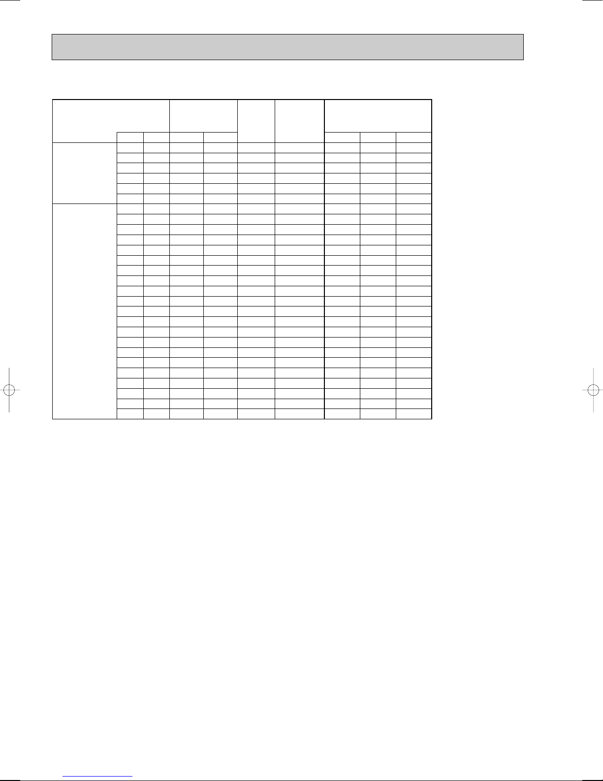
<Cooling>
7
<Cooling>
8
Number of operated indoor unit
Unit A Unit B Unit C Unit D Unit E Unit F Unit G Unit A Unit B Unit C Unit D Unit E Unit F Unit G
22 22 22 22 22 22 22 2000 2000 2000 2000 2000 2000 2000 14000 4980 21.9 21.0 22.9
22 22 22 22 22 22 25 1960 1960 1960 1960 1960 1960 2230 14000 4810 21.1 20.2 22.1
22 22 22 22 22 22 35 1840 1840 1840 1840 1840 1840 2930 14000 4310 18.9 18.1 19.8
22 22 22 22 22 22 50 1690 1690 1690 1690 1690 1690 3850 14000 3730 16.4 15.7 17.1
22 22 22 22 22 25 25 1920 1920 1920 1920 1920 2190 2190 14000 4650 20.4 19.6 21.3
22 22 22 22 22 25 35 1810 1810 1810 1810 1810 2060 2880 14000 4180 18.4 17.6 19.2
22 22 22 22 22 25 50 1660 1660 1660 1660 1660 1890 3780 14000 3630 15.9 15.3 16.7
22 22 22 22 22 35 35 1710 1710 1710 1710 1710 2720 2720 14000 3790 16.6 16.0 17.4
22 22 22 22 25 25 25 1890 1890 1890 1890 2140 2140 2140 14000 4500 19.8 18.9 20.7
22 22 22 22 25 25 35 1780 1780 1780 1780 2020 2020 2830 14000 4050 17.8 17.0 18.6
22 22 22 22 25 35 35 1680 1680 1680 1680 1910 2680 2680 14000 3690 16.2 15.5 16.9
22 22 22 25 25 25 25 1850 1850 1850 2110 2110 2110 2110 14000 4350 19.1 18.3 20.0
22 22 22 25 25 25 35 1750 1750 1750 1990 1990 1990 2780 14000 3940 17.3 16.6 18.1
22 22 25 25 25 25 25 1820 1820 2070 2070 2070 2070 2070 14000 4220 18.5 17.8 19.4
22 22 25 25 25 25 35 1710 1710 1960 1960 1960 1960 2740 14000 3830 16.8 16.1 17.6
22 25 25 25 25 25 25 1790 2030 2030 2030 2030 2030 2030 14000 4090 18.0 17.2 18.8
22 25 25 25 25 25 35 1690 1920 1920 1920 1920 1920 2690 14000 3730 16.4 15.7 17.1
25 25 25 25 25 25 25 2000 2000 2000 2000 2000 2000 2000 14000 3980 17.5 16.8 18.3
25 25 25 25 25 25 35 1890 1890 1890 1890 1890 1890 2650 14000 3630 15.9 15.3 16.7
Number of operated indoor unit
Unit A Unit B Unit C Unit D Unit E Unit F Unit G Unit H Unit A Unit B Unit C Unit D Unit E Unit F Unit G Unit H
22 22 22 22 22 22 22 22 1750 1750 1750 1750 1750 1750 1750 1750 14000 3940 17.3 16.6 18.1
22 22 22 22 22 22 22 25 1720 1720 1720 1720 1720 1720 1720 1960 14000 3830 16.8 16.1 17.6
22 22 22 22 22 22 25 25 1690 1690 1690 1690 1690 1690 1920 1920 14000 3730 16.4 15.7 17.1
22 22 22 22 22 25 25 25 1660 1660 1660 1660 1660 1890 1890 1890 14000 3630 15.9 15.3 16.7
Capacity of each unit
Capacity of each unit
(W)
(W)
Total
rated
capacity
(W)
Total
rated
capacity
(W)
Outdoor unit
)
input (W
Outdoor unit
)
input (W
Outdoor unit current
230V 240V 220V
Outdoor unit current
230V 240V 220V
(A)
(A)
21
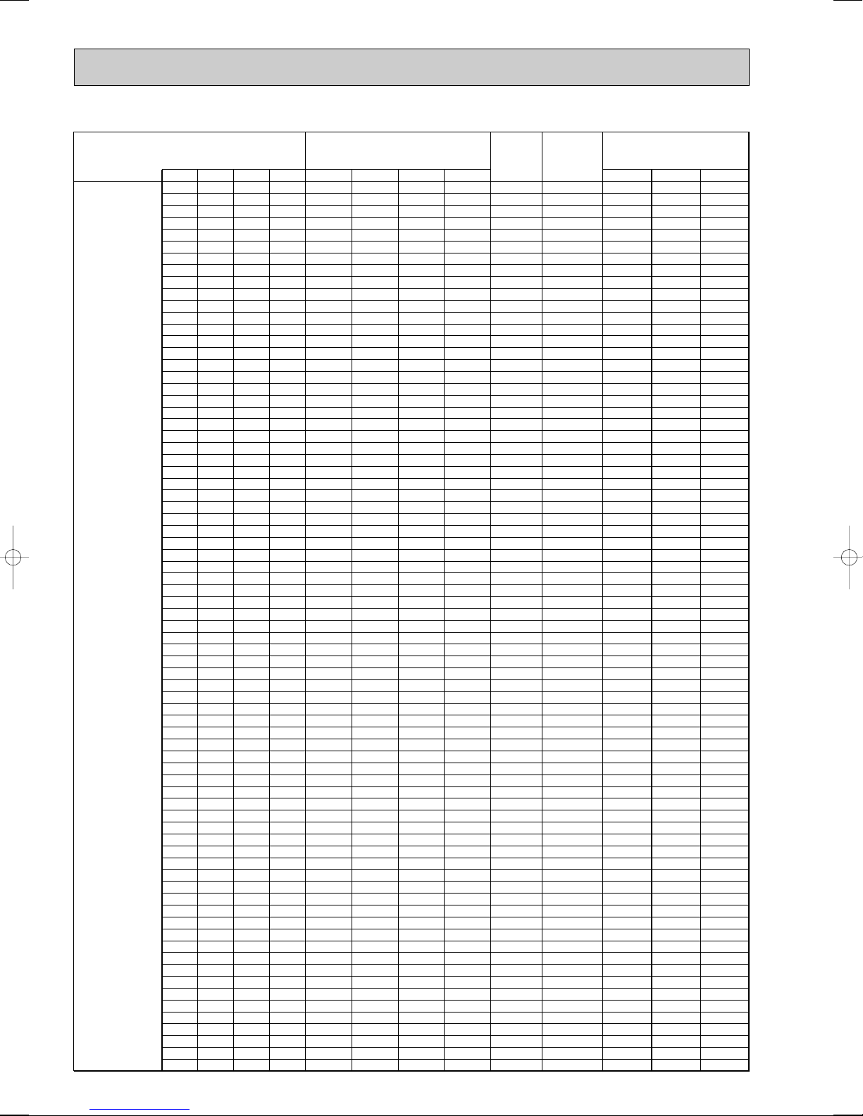
(2) Heating mode
<Heating>
Number of operated indoor unit
Unit A Unit B Unit A Unit B
22 – 3300 – 3300 1130 5.0 4.8 5.2
25 – 3600 – 3600 1240 5.4 5.2 5.7
1
2
35 – 4000 – 4000 1370 6.0 5.8 6.3
50 – 7200 – 7200 2470 10.8 10.4 11.3
60 – 7900 – 7900 2740 12.0 11.5 12.6
71 – 8600 – 8600 3020 13.3 12.7 13.9
22 22 2500 2500 5000 1720 7.6 7.2 7.9
22 25 2530 2870 5400 1860 8.2 7.8 8.5
22 35 2510 3990 6500 2250 9.9 9.5 10.3
22 50 2510 5690 8200 2880 12.6 12.1 13.2
22 60 2520 6880 9400 3340 14.7 14.1 15.3
22 71 2510 8090 10600 3810 16.7 16.0 17.5
25 25 2850 2850 5700 1960 8.6 8.2 9.0
25 35 2880 4020 6900 2400 10.5 10.1 11.0
25 50 2870 5730 8600 3030 13.3 12.8 13.9
25 60 2850 6850 9700 3450 15.2 14.5 15.8
25 71 2860 8140 11000 3960 17.4 16.7 18.2
35 35 4000 4000 8000 2810 12.3 11.8 12.9
35 50 3990 5710 9700 3450 15.2 14.5 15.8
35 60 4020 6880 10900 3920 17.2 16.5 18.0
35 71 4000 8100 12100 4350 19.1 18.3 20.0
50 50 5700 5700 11400 4120 18.1 17.3 18.9
50 60 5730 6870 12600 4510 19.8 19.0 20.7
50 71 5700 8100 13800 4880 21.4 20.5 22.4
60 60 6850 6850 13700 4850 21.3 20.4 22.3
60 71 6870 8130 15000 5260 23.1 22.1 24.2
71 71 8000 8000 16000 5430 23.8 22.9 24.9
Capacity of
each unit (W
)
Total
rated
capacity
(W)
Outdoor unit
input (W
)
Outdoor unit current (A
230V 240V 220V
)
22

<Heating>
Number of operated indoor unit
Unit A Unit B Unit C Unit A Unit B Unit C
22 22 22 2500 2500 2500 7500 2620 11.5 11.0 12.0
22 22 25 2520 2520 2860 7900 2770 12.2 11.7 12.7
22 22 35 2510 2510 3980 9000 3190 14.0 13.4 14.6
22 22 50 2500 2500 5690 10700 3850 16.9 16.2 17.7
22 22 60 2520 2520 6860 11900 4280 18.8 18.0 19.7
22 22 71 2510 2510 8090 13100 4660 20.5 19.6 21.4
22 25 25 2500 2850 2850 8200 2880 12.6 12.1 13.2
22 25 35 2520 2870 4010 9400 3340 14.7 14.1 15.3
22 25 50 2520 2860 5720 11100 4000 17.6 16.8 18.4
22 25 60 2510 2850 6840 12200 4380 19.2 18.4 20.1
22 25 71 2520 2860 8120 13500 4790 21.0 20.2 22.0
22 35 35 2510 3990 3990 10500 3770 16.6 15.9 17.3
22 35 50 2510 3990 5700 12200 4380 19.2 18.4 20.1
22 35 60 2520 4010 6870 13400 4760 20.9 20.0 21.9
22 35 71 2510 3990 8100 14600 5130 22.5 21.6 23.6
22 50 50 2500 5700 5700 13900 4910 21.6 20.7 22.5
22 50 60 2520 5720 6860 15100 5290 23.2 22.3 24.3
22 50 71 2460 5590 7940 16000 5370 23.6 22.6 24.7
22 60 60 2480 6760 6760 16000 5430 23.8 22.9 24.9
22 60 71 2300 6270 7420 16000 4880 21.4 20.5 22.4
22 71 71 2140 6930 6930 16000 4430 19.5 18.6 20.3
25 25 25 2860 2860 2860 8600 3030 13.3 12.8 13.9
25 25 35 2850 2850 3990 9700 3450 15.2 14.5 15.8
25 25 50 2850 2850 5700 11400 4120 18.1 17.3 18.9
25 25 60 2860 2860 6870 12600 4510 19.8 19.0 20.7
3
25 25 71 2850 2850 8100 13800 4880 21.4 20.5 22.4
25 35 35 2860 4020 4020 10900 3920 17.2 16.5 18.0
25 35 50 2860 4010 5730 12600 4510 19.8 19.0 20.7
25 35 60 2850 4000 6850 13700 4850 21.3 20.4 22.3
25 35 71 2860 4010 8130 15000 5260 23.1 22.1 24.2
25 50 50 2860 5720 5720 14300 5040 22.1 21.2 23.1
25 50 60 2850 5700 6840 15400 5380 23.6 22.6 24.7
25 50 71 2740 5480 7780 16000 5210 22.9 21.9 23.9
25 60 60 2760 6620 6620 16000 5270 23.1 22.2 24.2
25 60 71 2560 6150 7280 16000 4750 20.9 20.0 21.8
25 71 71 2400 6800 6800 16000 4320 19.0 18.2 19.8
35 35 35 4000 4000 4000 12000 4320 19.0 18.2 19.8
35 35 50 4000 4000 5700 13700 4850 21.3 20.4 22.3
35 35 60 4010 4010 6880 14900 5230 23.0 22.0 24.0
35 35 71 3970 3970 8060 16000 5480 24.1 23.1 25.2
35 50 50 3990 5700 5700 15400 5380 23.6 22.6 24.7
35 50 60 3860 5520 6620 16000 5270 23.1 22.2 24.2
35 50 71 3590 5130 7280 16000 4750 20.9 20.0 21.8
35 60 60 3610 6190 6190 16000 4790 21.0 20.2 22.0
35 60 71 3370 5780 6840 16000 4350 19.1 18.3 20.0
35 71 71 3160 6420 6420 16000 3990 17.5 16.8 18.3
50 50 50 5330 5330 5330 16000 5020 22.0 21.1 23.0
50 50 60 5000 5000 6000 16000 4580 20.1 19.3 21.0
50 50 71 4680 4680 6640 16000 4180 18.4 17.6 19.2
50 60 60 4700 5650 5650 16000 4210 18.5 17.7 19.3
50 60 71 4420 5300 6280 16000 3870 17.0 16.3 17.8
60 60 60 5330 5330 5330 16000 3900 17.1 16.3 17.8
Capacity of each unit (W
)
capacity
Total
rated
(W)
Outdoor unit
input (W
)
Outdoor unit current (A
230V 240V 220V
)
23
<Heating>
Number of operated indoor unit
Unit A Unit B Unit C Unit D Unit A Unit B Unit C Unit D
22 22 22 22 2520 2520 2520 2520 10100 3610 15.9 15.2 16.6
22 22 22 25 2510 2510 2510 2860 10400 3730 16.4 15.7 17.1
22 22 22 35 2500 2500 2500 3990 11500 4150 18.2 17.5 19.1
22 22 22 50 2520 2520 2520 5730 13300 4730 20.8 19.9 21.7
22 22 22 60 2510 2510 2510 6860 14400 5070 22.3 21.3 23.3
22 22 22 71 2520 2520 2520 8140 15700 5470 24.0 23.0 25.1
22 22 25 25 2500 2500 2850 2850 10700 3850 16.9 16.2 17.7
22 22 25 35 2520 2520 2860 4000 11900 4280 18.8 18.0 19.7
22 22 25 50 2510 2510 2860 5710 13600 4820 21.2 20.3 22.1
22 22 25 60 2510 2510 2850 6830 14700 5160 22.7 21.7 23.7
22 22 25 71 2510 2510 2860 8110 16000 5540 24.3 23.3 25.4
22 22 35 35 2510 2510 3990 3990 13000 4630 20.3 19.5 21.3
22 22 35 50 2510 2510 3990 5690 14700 5160 22.7 21.7 23.7
22 22 35 60 2520 2520 4000 6860 15900 5530 24.3 23.3 25.4
22 22 35 71 2350 2350 3730 7570 16000 5020 22.0 21.1 23.0
22 22 50 50 2440 2440 5560 5560 16000 5320 23.4 22.4 24.4
22 22 50 60 2290 2290 5190 6230 16000 4830 21.2 20.3 22.2
22 22 50 71 2130 2130 4850 6880 16000 4390 19.3 18.5 20.2
22 22 60 60 2150 2150 5850 5850 16000 4430 19.5 18.6 20.3
22 22 60 71 2010 2010 5490 6490 16000 4050 17.8 17.0 18.6
22 25 25 25 2520 2860 2860 2860 11100 4000 17.6 16.8 18.4
22 25 25 35 2510 2850 2850 3990 12200 4380 19.2 18.4 20.1
22 25 25 50 2510 2850 2850 5690 13900 4910 21.6 20.7 22.5
22 25 25 60 2520 2860 2860 6860 15100 5290 23.2 22.3 24.3
22 25 25 71 2460 2800 2800 7940 16000 5370 23.6 22.6 24.7
22 25 35 35 2520 2860 4010 4010 13400 4760 20.9 20.0 21.9
22 25 35 50 2520 2860 4000 5720 15100 5290 23.2 22.3 24.3
22 25 35 60 2480 2820 3940 6760 16000 5430 23.8 22.9 24.9
22 25 35 71 2300 2610 3660 7420 16000 4880 21.4 20.5 22.4
22 25 50 50 2390 2720 5440 5440 16000 5160 22.7 21.7 23.7
22 25 50 60 2240 2550 5100 6110 16000 4700 20.6 19.8 21.6
22 25 50 71 2100 2380 4760 6760 16000 4280 18.8 18.0 19.7
22 25 60 60 2100 2400 5750 5750 16000 4320 19.0 18.2 19.8
22 25 60 71 1980 2250 5390 6380 16000 3960 17.4 16.7 18.2
22 35 35 35 2500 4000 4000 4000 14500 5100 22.4 21.5 23.4
22 35 35 50 2480 3940 3940 5630 16000 5430 23.8 22.9 24.9
4
22 35 35 60 2320 3680 3680 6320 16000 4920 21.6 20.7 22.6
22 35 35 71 2160 3440 3440 6960 16000 4460 19.6 18.8 20.5
22 35 50 50 2230 3570 5100 5100 16000 4700 20.6 19.8 21.6
22 35 50 60 2110 3350 4790 5750 16000 4320 19.0 18.2 19.8
22 35 50 71 1980 3150 4490 6380 16000 3960 17.4 16.7 18.2
22 35 60 60 1990 3160 5420 5420 16000 3990 17.5 16.8 18.3
22 50 50 50 2050 4650 4650 4650 16000 4150 18.2 17.5 19.1
22 50 50 60 1930 4400 4400 5270 16000 3850 16.9 16.2 17.7
25 25 25 25 2850 2850 2850 2850 11400 4120 18.1 17.3 18.9
25 25 25 35 2860 2860 2860 4010 12600 4510 19.8 19.0 20.7
25 25 25 50 2860 2860 2860 5720 14300 5040 22.1 21.2 23.1
25 25 25 60 2850 2850 2850 6840 15400 5380 23.6 22.6 24.7
25 25 25 71 2740 2740 2740 7780 16000 5210 22.9 21.9 23.9
25 25 35 35 2850 2850 4000 4000 13700 4850 21.3 20.4 22.3
25 25 35 50 2850 2850 3990 5700 15400 5380 23.6 22.6 24.7
25 25 35 60 2760 2760 3860 6620 16000 5270 23.1 22.2 24.2
25 25 35 71 2560 2560 3590 7280 16000 4750 20.9 20.0 21.8
25 25 50 50 2670 2670 5330 5330 16000 5020 22.0 21.1 23.0
25 25 50 60 2500 2500 5000 6000 16000 4580 20.1 19.3 21.0
25 25 50 71 2340 2340 4680 6640 16000 4180 18.4 17.6 19.2
25 25 60 60 2350 2350 5650 5650 16000 4210 18.5 17.7 19.3
25 25 60 71 2210 2210 5300 6280 16000 3870 17.0 16.3 17.8
25 35 35 35 2870 4010 4010 4010 14900 5230 23.0 22.0 24.0
25 35 35 50 2760 3860 3860 5520 16000 5270 23.1 22.2 24.2
25 35 35 60 2580 3610 3610 6190 16000 4790 21.0 20.2 22.0
25 35 35 71 2410 3370 3370 6840 16000 4350 19.1 18.3 20.0
25 35 50 50 2500 3500 5000 5000 16000 4580 20.1 19.3 21.0
25 35 50 60 2350 3290 4710 5650 16000 4210 18.5 17.7 19.3
25 35 50 71 2210 3090 4420 6280 16000 3870 17.0 16.3 17.8
25 35 60 60 2220 3110 5330 5330 16000 3900 17.1 16.4 17.9
25 50 50 50 2290 4570 4570 4570 16000 4050 17.8 17.0 18.6
25 50 50 60 2160 4320 4320 5190 16000 3760 16.5 15.8 17.3
35 35 35 35 4000 4000 4000 4000 16000 5540 24.3 23.3 25.4
35 35 35 50 3610 3610 3610 5160 16000 4790 21.0 20.2 22.0
35 35 35 60 3390 3390 3390 5820 16000 4390 19.3 18.5 20.2
35 35 35 71 3180 3180 3180 6450 16000 4020 17.7 16.9 18.5
35 35 50 50 3290 3290 4710 4710 16000 4210 18.5 17.7 19.3
35 35 50 60 3110 3110 4440 5330 16000 3900 17.1 16.4 17.9
35 50 50 50 3030 4320 4320 4320 16000 3760 16.5 15.8 17.3
Capacity of each unit (W
24
Total
Outdoor unit
)
rated
capacity
(W)
input (W
Outdoor unit current (A
)
230V 240V 220V
)
<Heating>
Number of operated indoor unit
5
Total
Outdoor unit
Capacity of each unit (W
Unit A Unit B Unit C Unit D Unit E Unit A Unit B Unit C Unit D Unit E
22 22 22 22 22 2520 2520 2520 2520 2520 12600 4510 19.8 19.0 20.7
22 22 22 22 25 2510 2510 2510 2510 2850 12900 4600 20.2 19.4 21.1
22 22 22 22 35 2520 2520 2520 2520 4010 14100 4980 21.9 21.0 22.9
22 22 22 22 50 2520 2520 2520 2520 5720 15800 5500 24.2 23.1 25.3
22 22 22 22 60 2380 2380 2380 2380 6480 16000 5110 22.4 21.5 23.5
22 22 22 22 71 2210 2210 2210 2210 7140 16000 4620 20.3 19.4 21.2
22 22 22 25 25 2520 2520 2520 2870 2870 13300 4730 20.8 19.9 21.7
22 22 22 25 35 2510 2510 2510 2860 4000 14400 5070 22.3 21.3 23.3
22 22 22 25 50 2500 2500 2500 2840 5660 16000 5480 24.1 23.1 25.2
22 22 22 25 60 2330 2330 2330 2650 6360 16000 4970 21.8 20.9 22.8
22 22 22 25 71 2170 2170 2170 2470 7010 16000 4500 19.8 18.9 20.7
22 22 22 35 35 2510 2510 2510 3980 3980 15500 5410 23.8 22.8 24.8
22 22 22 35 50 2330 2330 2330 3710 5300 16000 4970 21.8 20.9 22.8
22 22 22 35 60 2190 2190 2190 3480 5950 16000 4540 19.9 19.1 20.8
22 22 22 35 71 2050 2050 2050 3260 6590 16000 4150 18.2 17.5 19.1
22 22 22 50 50 2120 2120 2120 4820 4820 16000 4350 19.1 18.3 20.0
22 22 22 50 60 2000 2000 2000 4550 5450 16000 4020 17.7 16.9 18.5
22 22 25 25 25 2510 2510 2860 2860 2860 13600 4820 21.2 20.3 22.1
22 22 25 25 35 2510 2510 2850 2850 3980 14700 5160 22.7 21.7 23.7
22 22 25 25 50 2440 2440 2780 2780 5560 16000 5320 23.4 22.4 24.4
22 22 25 25 60 2290 2290 2600 2600 6220 16000 4830 21.2 20.3 22.2
22 22 25 25 71 2130 2130 2420 2420 6880 16000 4390 19.3 18.5 20.2
22 22 25 35 35 2520 2520 2860 4000 4000 15900 5530 24.3 23.3 25.4
22 22 25 35 50 2290 2290 2600 3640 5180 16000 4830 21.2 20.3 22.2
22 22 25 35 60 2150 2150 2440 3410 5850 16000 4430 19.5 18.6 20.3
22 22 25 35 71 2010 2010 2290 3200 6490 16000 4050 17.8 17.0 18.6
22 22 25 50 50 2080 2080 2370 4730 4730 16000 4250 18.7 17.9 19.5
22 22 25 50 60 1970 1970 2230 4470 5360 16000 3930 17.3 16.5 18.0
22 22 35 35 35 2360 2360 3760 3760 3760 16000 5060 22.2 21.3 23.2
22 22 35 35 50 2150 2150 3410 3410 4880 16000 4430 19.5 18.6 20.3
22 22 35 35 60 2020 2020 3220 3220 5520 16000 4080 17.9 17.2 18.7
22 22 35 35 71 1900 1900 3030 3030 6140 16000 3760 16.5 15.8 17.3
22 22 35 50 50 1970 1970 3120 4470 4470 16000 3930 17.3 16.5 18.0
22 25 25 25 25 2500 2850 2850 2850 2850 13900 4910 21.6 20.7 22.5
22 25 25 25 35 2520 2860 2860 2860 4000 15100 5290 23.2 22.3 24.3
22 25 25 25 50 2390 2720 2720 2720 5440 16000 5160 22.7 21.7 23.7
22 25 25 25 60 2240 2550 2550 2550 6110 16000 4700 20.6 19.8 21.6
22 25 25 25 71 2100 2380 2380 2380 6760 16000 4280 18.8 18.0 19.7
22 25 25 35 35 2480 2820 2820 3940 3940 16000 5430 23.8 22.9 24.9
22 25 25 35 50 2240 2550 2550 3570 5090 16000 4700 20.6 19.8 21.6
22 25 25 35 60 2110 2400 2400 3350 5740 16000 4320 19.0 18.2 19.8
22 25 25 35 71 1980 2250 2250 3150 6370 16000 3960 17.4 16.7 18.2
22 25 25 50 50 2040 2330 2330 4650 4650 16000 4150 18.2 17.5 19.1
22 25 25 50 60 1930 2200 2200 4400 5270 16000 3850 16.9 16.2 17.7
22 25 35 35 35 2320 2630 3680 3680 3680 16000 4920 21.6 20.7 22.6
22 25 35 35 50 2110 2400 3350 3350 4790 16000 4320 19.0 18.2 19.8
22 25 35 35 60 1990 2260 3160 3160 5420 16000 3990 17.5 16.8 18.3
22 25 35 50 50 1920 2200 3080 4400 4400 16000 3850 16.9 16.2 17.7
22 35 35 35 35 2160 3460 3460 3460 3460 16000 4500 19.8 18.9 20.7
22 35 35 35 50 1990 3160 3160 3160 4520 16000 3990 17.5 16.8 18.3
25 25 25 25 25 2860 2860 2860 2860 2860 14300 5040 22.1 21.2 23.1
25 25 25 25 35 2850 2850 2850 2850 3990 15400 5380 23.6 22.6 24.7
25 25 25 25 50 2670 2670 2670 2670 5320 16000 5020 22.0 21.1 23.0
25 25 25 25 60 2500 2500 2500 2500 6000 16000 4580 20.1 19.3 21.0
25 25 25 25 71 2340 2340 2340 2340 6640 16000 4180 18.4 17.6 19.2
25 25 25 35 35 2760 2760 2760 3860 3860 16000 5270 23.1 22.2 24.2
25 25 25 35 50 2500 2500 2500 3500 5000 16000 4580 20.1 19.3 21.0
25 25 25 35 60 2350 2350 2350 3290 5650 16000 4210 18.5 17.7 19.3
25 25 25 35 71 2210 2210 2210 3090 6280 16000 3870 17.0 16.3 17.8
25 25 25 50 50 2290 2290 2290 4560 4560 16000 4050 17.8 17.0 18.6
25 25 25 50 60 2160 2160 2160 4320 5190 16000 3760 16.5 15.8 17.3
25 25 35 35 35 2580 2580 3610 3610 3610 16000 4790 21.0 20.2 22.0
25 25 35 35 50 2350 2350 3290 3290 4710 16000 4210 18.5 17.7 19.3
25 25 35 35 60 2220 2220 3110 3110 5330 16000 3900 17.1 16.4 17.9
25 25 35 50 50 2160 2160 3030 4320 4320 16000 3760 16.5 15.8 17.3
25 35 35 35 35 2420 3390 3390 3390 3390 16000 4390 19.3 18.5 20.2
25 35 35 35 50 2220 3110 3110 3110 4440 16000 3900 17.1 16.4 17.9
35 35 35 35 35 3200 3200 3200 3200 3200 16000 4050 17.8 17.0 18.6
)
rated
capacity
(W)
input (W
Outdoor unit current (A
)
230V 240V 220V
)
25
<Heating>
6
Total
Number of operated indoor unit
Unit A Unit B Unit C Unit D Unit E Unit F Unit A Unit B Unit C Unit D Unit E Unit F
22 22 22 22 22 22 2510 2510 2510 2510 2510 2510 15100 5290 23.2 22.3 24.3
22 22 22 22 22 25 2510 2510 2510 2510 2510 2850 15400 5380 23.6 22.6 24.7
22 22 22 22 22 35 2430 2430 2430 2430 2430 3850 16000 5270 23.1 22.2 24.2
22 22 22 22 22 50 2200 2200 2200 2200 2200 5000 16000 4580 20.1 19.3 21.0
22 22 22 22 22 60 2070 2070 2070 2070 2070 5650 16000 4210 18.5 17.7 19.3
22 22 22 22 22 71 1940 1940 1940 1940 1940 6280 16000 3870 17.0 16.3 17.8
22 22 22 22 25 25 2520 2520 2520 2520 2860 2860 15800 5500 24.2 23.1 25.3
22 22 22 22 25 35 2380 2380 2380 2380 2700 3780 16000 5110 22.4 21.5 23.5
22 22 22 22 25 50 2160 2160 2160 2160 2450 4910 16000 4460 19.6 18.8 20.5
22 22 22 22 25 60 2030 2030 2030 2030 2310 5550 16000 4120 18.1 17.3 18.9
22 22 22 22 25 71 1910 1910 1910 1910 2170 6170 16000 3790 16.6 16.0 17.4
22 22 22 22 35 35 2230 2230 2230 2230 3540 3540 16000 4660 20.5 19.6 21.4
22 22 22 22 35 50 2030 2030 2030 2030 3240 4620 16000 4120 18.1 17.3 18.9
22 22 22 22 35 60 1920 1920 1920 1920 3060 5250 16000 3820 16.8 16.1 17.5
22 22 22 25 25 25 2500 2500 2500 2830 2830 2830 16000 5480 24.1 23.1 25.2
22 22 22 25 25 35 2330 2330 2330 2650 2650 3710 16000 4970 21.8 20.9 22.8
22 22 22 25 25 50 2120 2120 2120 2410 2410 4820 16000 4350 19.1 18.3 20.0
22 22 22 25 25 60 2000 2000 2000 2270 2270 5450 16000 4020 17.7 16.9 18.5
22 22 22 25 35 35 2190 2190 2190 2470 3480 3480 16000 4540 19.9 19.1 20.8
22 22 22 25 35 50 2000 2000 2000 2270 3180 4550 16000 4020 17.7 16.9 18.5
22 22 22 35 35 35 2060 2060 2060 3270 3270 3270 16000 4180 18.4 17.6 19.2
22 22 25 25 25 25 2440 2440 2780 2780 2780 2780 16000 5320 23.4 22.4 24.4
22 22 25 25 25 35 2280 2280 2600 2600 2600 3640 16000 4830 21.2 20.3 22.2
22 22 25 25 25 50 2080 2080 2370 2370 2370 4730 16000 4250 18.7 17.9 19.5
22 22 25 25 25 60 1970 1970 2230 2230 2230 5360 16000 3930 17.3 16.5 18.0
22 22 25 25 35 35 2150 2150 2440 2440 3410 3410 16000 4430 19.5 18.6 20.3
22 22 25 25 35 50 1970 1970 2230 2230 3130 4470 16000 3930 17.3 16.5 18.0
22 22 25 35 35 35 2020 2020 2300 3220 3220 3220 16000 4080 17.9 17.2 18.7
22 22 35 35 35 35 1910 1910 3040 3040 3040 3040 16000 3790 16.6 16.0 17.4
22 25 25 25 25 25 2390 2720 2720 2720 2720 2720 16000 5160 22.7 21.7 23.7
22 25 25 25 25 35 2240 2550 2550 2550 2550 3560 16000 4700 20.6 19.8 21.6
22 25 25 25 25 50 2040 2330 2330 2330 2330 4640 16000 4150 18.2 17.5 19.1
22 25 25 25 25 60 1930 2200 2200 2200 2200 5270 16000 3850 16.9 16.2 17.7
22 25 25 25 35 35 2100 2400 2400 2400 3350 3350 16000 4320 19.0 18.2 19.8
22 25 25 25 35 50 1930 2200 2200 2200 3080 4390 16000 3850 16.9 16.2 17.7
22 25 25 35 35 35 1990 2260 2260 3160 3160 3160 16000 3990 17.5 16.8 18.3
25 25 25 25 25 25 2660 2660 2660 2660 2660 2660 16000 5020 22.0 21.1 23.0
25 25 25 25 25 35 2500 2500 2500 2500 2500 3500 16000 4580 20.1 19.3 21.0
25 25 25 25 25 50 2280 2280 2280 2280 2280 4570 16000 4050 17.8 17.0 18.6
25 25 25 25 25 60 2160 2160 2160 2160 2160 5190 16000 3760 16.5 15.8 17.3
25 25 25 25 35 35 2350 2350 2350 2350 3290 3290 16000 4210 18.5 17.7 19.3
25 25 25 25 35 50 2160 2160 2160 2160 3030 4320 16000 3760 16.5 15.8 17.3
25 25 25 35 35 35 2220 2220 2220 3110 3110 3110 16000 3900 17.1 16.4 17.9
Capacity of each unit (W
)
rated
capacity
(W)
Outdoor unit
)
input (W
Outdoor unit current (A
230V 240V 220V
)
26

<Heating>
7
<Heating>
8
Total
Number of operated indoor unit
Unit A Unit B Unit C Unit D Unit E Unit F Unit G Unit A Unit B Unit C Unit D Unit E Unit F Unit G
22 22 22 22 22 22 22 2280 2280 2280 2280 2280 2280 2280 16000 4830 21.2 20.3 22.2
22 22 22 22 22 22 25 2240 2240 2240 2240 2240 2240 2550 16000 4700 20.6 19.8 21.6
22 22 22 22 22 22 35 2110 2110 2110 2110 2110 2110 3340 16000 4320 19.0 18.2 19.8
22 22 22 22 22 22 50 1930 1930 1930 1930 1930 1930 4400 16000 3850 16.9 16.2 17.7
22 22 22 22 22 25 25 2200 2200 2200 2200 2200 2500 2500 16000 4580 20.1 19.3 21.0
22 22 22 22 22 25 35 2070 2070 2070 2070 2070 2350 3290 16000 4210 18.5 17.7 19.3
22 22 22 22 22 25 50 1900 1900 1900 1900 1900 2160 4320 16000 3760 16.5 15.8 17.3
22 22 22 22 22 35 35 1960 1960 1960 1960 1960 3100 3100 16000 3900 17.1 16.4 17.9
22 22 22 22 25 25 25 2160 2160 2160 2160 2450 2450 2450 16000 4460 19.6 18.8 20.5
22 22 22 22 25 25 35 2030 2030 2030 2030 2310 2310 3240 16000 4120 18.1 17.3 18.9
22 22 22 22 25 35 35 1920 1920 1920 1920 2190 3060 3060 16000 3820 16.8 16.1 17.5
22 22 22 25 25 25 25 2120 2120 2120 2410 2410 2410 2410 16000 4350 19.1 18.3 20.0
22 22 22 25 25 25 35 2000 2000 2000 2270 2270 2270 3180 16000 4020 17.7 16.9 18.5
22 22 25 25 25 25 25 2070 2070 2370 2370 2370 2370 2370 16000 4250 18.7 17.9 19.5
22 22 25 25 25 25 35 1970 1970 2230 2230 2230 2230 3130 16000 3930 17.3 16.5 18.0
22 25 25 25 25 25 25 2050 2320 2320 2320 2320 2320 2320 16000 4150 18.2 17.5 19.1
22 25 25 25 25 25 35 1930 2200 2200 2200 2200 2200 3070 16000 3850 16.9 16.2 17.7
25 25 25 25 25 25 25 2280 2280 2280 2280 2280 2280 2280 16000 4050 17.8 17.0 18.6
25 25 25 25 25 25 35 2160 2160 2160 2160 2160 2160 3030 16000 3760 16.5 15.8 17.3
Number of operated indoor unit
Unit A Unit B Unit C Unit D Unit E Unit F Unit G Unit H Unit A Unit B Unit C Unit D Unit E Unit F Unit G Unit H
22 22 22 22 22 22 22 22 2000 2000 2000 2000 2000 2000 2000 2000 16000 4020 17.7 16.9 18.5
22 22 22 22 22 22 22 25 1960 1960 1960 1960 1960 1960 1960 2230 16000 3930 17.3 16.5 18.0
22 22 22 22 22 22 25 25 1930 1930 1930 1930 1930 1930 2200 2200 16000 3850 16.9 16.2 17.7
22 22 22 22 22 25 25 25 1900 1900 1900 1900 1900 2160 2160 2160 16000 3760 16.5 15.8 17.3
Capacity of each unit
Capacity of each unit
(W)
(W)
rated
capacity
(W)
Total
rated
capacity
(W)
Outdoor unit
)
input (W
Outdoor unit
)
input (W
Outdoor unit current
230V 240V 220V
Outdoor unit current
230V 240V 220V
(A)
(A)
27

5-2. CORRECTING COOLING AND HEATING CAPACITY
Rated cooling capacity
Rated heating capacity
Indoor D.B. 27°C / W.B. 19°C
Outdoor D.B. 35°C
Indoor D.B. 20°C
Outdoor D.B. 7°C / W.B. 6°C
–5 0 5 10 15 20 25 30 35 40 46
16
18
20
22
0.6
0.8
1
1.2
1.4
Cooling capacity ratio
Outdoor intake air dry-bulb temperature <:D.B. >
–5 0 5 10 15 20 25 30 35 40 46
16
18
20
22
0.4
0.6
0.8
1.0
1.2
Cooling input ratio
Outdoor intake air dry-bulb temperature <:D.B. >
5-2-1. Correcting Changes in Air Conditions
(1)The performance curve charts (Figure 1-1, 1-2, 2-1, 2-2) show the change ratio of capacity and input (power consumption)
according to the indoor and outdoor temperature condition when define the rated capacity (total capacity) and rated input
under the standard condition in standard piping length (5m) as “1.0”.
• Standard conditions:
• Use the rated capacity and rated power values given in the characteristics table for each indoor unit.
• The capacity is the single value on the side of the outdoor unit;
The capacity on the sides of each indoor unit must be added to obtain the total capacity.
(2)The capacity of each indoor unit may be obtained by multiplying the total capacity obtained in (1) by the ratio between the
individual capacity at the rated time and the total capacity at the rated time.
Individual capacity under stated conditions =Total capacity under the stated conditions o
(3) Capacity correction factor curve
Fig.1-1
Cooling capacity
Indoor intake air wet-bulb temperature <:W.B.>
Fig.2-1
Heating capacity
Fig.1-2
Cooling input
Fig.2-2
Heating input
Individual capacity at the rated time
Total capacity at the rated time
Indoor intake air wet-bulb temperature <:W.B.>
Indoor intake air dry-bulb temperature <:D.B.>
Outdoor intake air wet-bulb temperature <:W.B.> Outdoor intake air wet-bulb temperature <:W.B.>
Note : These diagrams show the case where the operation frequency of a compressor is fixed.
Indoor intake air dry-bulb temperature <:D.B.>
28

5-2-2. Correcting Capacity for Changes in the Length of Refrigerant Piping
2.2(15.7%)
7.0 (50%)
10.5 (75%)
14.0 (100%)
18.5 (132%)
0.65
20 40 60 80
20 40 60 80
0.70
0.75
0.80
0.85
0.90
0.95
1.00
0.9
20 40 60 80
0.95
1
To obtain the ratio (and the corrected piping length) of the outdoor units rated capacity and the total in-use indoor capacity, first
find the capacity ratio corresponding to the standard piping length from Fig.3, Fig.4 and then multiply by the capacity from
Fig.1-1, 1-2, Fig.2-1, 2-2 to obtain the actual capacity.
(1) Capacity correction factor
Fig.3 Cooling capacity correction curve
Total rated capacity of indoor units (kW)
Cooling
Capacity
(ratio)
[%]
Corrected piping length (m)
Fig.4 Heating capacity correction curve
Heating
Capacity
(ratio)
[%]
Corrected piping length (m)
(2) Method for Obtaining the Corrected Piping Length
Corrected piping length = (Actual piping length between outdoor unit and the farthest indoor unit) + (0.30 o number of bends in the
piping) (m)
29

5-3. NOISE CRITERION CURVES
90
80
70
60
50
40
30
20
10
63 125 250 500 1000 2000 4000 8000
APPROXIMATE
THRESHOLD OF
HEARING FOR
CONTINUOUS
NOISE
OCTAVE BAND SOUND PRESSURE LEVEL, dB (0 dB = 0.0002 µbar)
BAND CENTER FREQUENCIES, Hz
NC-60
NC-50
NC-40
NC-30
NC-20
NC-70
MXZ-8A140VA
MXZ-8A140VA
1
MXZ-8A140VA2
MXZ-8A140VA3
COOLING
MODE
HEATING
50
SPL(dB)
52
LINE
MICROPHONE
1m
1.5m
UNIT
GROUND
30

6 OUTLINES AND DIMENSIONS
Handle for moving
Service panel
Earth terminal
Left····Power supply wiring
Right··Indoor/Outdoor wiring
Terminal connection
Rear piping cover
Front piping cover
Side Air Intake
Rear Air Intake
Air Discharge
81 219
14514522030 145
71
71
Drain hole
(5-[33)
Bottom piping hole
(Knockout)
600175 175
330
417
53
1928
370
37
56
4256
2-U Shaped notched holes
(Foundation Bolt M10)
2-12 o 36 Oval holes
(Foundation Bolt M10)
Installation Feet
,
,
,
,
,
,
,
,
,,
,
,
,,
,
,
,
,,
,
,
,,
,,
,
,,
,
,
,
,
,
,,
,
,
,
,,
,
,
,,
,
,
,
,
30
1079
*1 507
*1 423
1350
23
950
371 635
322
2
1
Handle for moving
,
,
,,
,,
,,
,,
,
,,
,,
,
,
,
,,
,
,,
,
,,
,
,
,
,
,
,
,,
,
,,
,
,
,
,
,,
,
,
,
,,
,
,
,,
,
,,
,,
,
,,
,
,
,
,
,
,
,,
,
,
,,,
,
,
,
,
,,
,,
,
,,
,,
,,
,,
,,
,
,
,,
,
,
,,
,
,
,
,
,,
,,
,
,
,
,,
,
,
,
,
,
,
,
,
,
,
,
,
,
,
,
,
,
,
,
,
,
,
,
,
,
,
,
,
,
,
,
,
,
,
,
,
,
,
,
,
,
,
,
,
,
,
,
,
,
,
,
,
,
,
,
,
,,
,
,
,
,
,
,
,
,
,
,
,
,
,
,
,
,
,
,
,
,
,
,
,,
,,
,
,
,
,
,
,
,
,
,
,
,
,
,
,
,
,
,
,
,
,
,
,
,,
,
,
,
,
,
,
,
,
,
,
,
,
,
,
,
,
,
,
,
,
,
,
,
,
,
,
,
,
,
,
,
,
,
,
,
,
,
,
,
,
,
,
,
,
,
,
,
,
,
,
,
,
,
,
,
,
,
,
,
,
,
,
,
,
,
,
,
,
Over
Over
Over
Over
Less than
Piping and wiring connections
can be made from 4 directions:
front, right, rear and below.
4 PIPING-WIRING DIRECTIONS
3 FOUNDATION BOLTS
2 SERVICE SPACE
1 FREE SPACE (Around the unit)
Please secure the unit firmly
with 4 foundation (M10) bolts.
(Bolts and washers must be
purchased locally.)
<Foundation bolt height>
Dimensions of space needed
for service access are
shown in the below diagram.
The diagram below shows a basic
example.
Explanation of particular details are
given in the installation manuals etc.
FREE
Over 10mm
Over 10mm
Over 150mm
Over 1000mm
30
FOUNDATION
10
500
500
150
Service space
Piping Knockout Hole Details
637323
5527
92
65
4045
Power supply wiring hole
(2-[27Knockout)
Rear trunking hole
(Knockout)
Rear piping hole
(Knockout)
[
92
922723
63
73
4075
92
5519
Power supply wiring hole
(2-[27Knockout)
Right trunking hole
(Knockout)
Right piping hole
(Knockout)
[
92
637323
5527
40 45
65
92
Power supply wiring hole
(2-[27Knockout)
Front trunking hole
(Knockout)
Front piping hole
(Knockout)
[
92
Handle for moving
Handle for moving
Rear Air Intake
Air intake
Side Air Intake
Handle for moving
Example of Notes
1···Refrigerant GAS pipe connection (FLARE)[15.88(5/8 inch)
2···Refrigerant LIQUID pipe connection (FLARE)[9.52(3/8 inch)
Indication of STOP VALVE connection location
6-1. OUTDOOR UNIT unit : mm
MXZ-8A140VA MXZ-8A140VA1 MXZ-8A140VA2
31
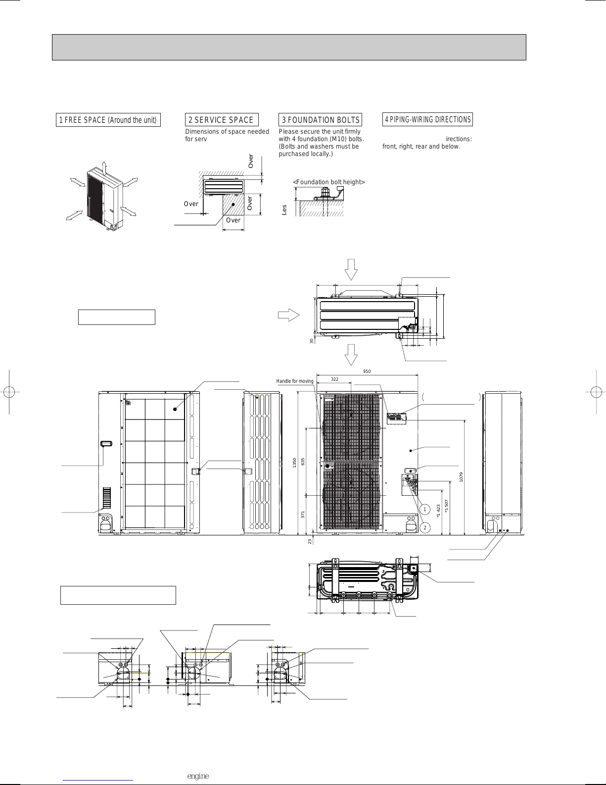
MXZ-8A140VA3
Handle for moving
Service panel
Earth terminal
Left····Power supply wiring
Right··Indoor/Outdoor wiring
Terminal connection
Rear piping cover
Front piping cover
Side Air Intake
Rear Air Intake
Air Discharge
81 219
14514522030 145
71
71
Drain hole
(5-[33)
Bottom piping hole
(Knockout)
600175 175
330
417
53
1928
370
37
56
4256
2-U Shaped notched holes
(Foundation Bolt M10)
2-12 o 36 Oval holes
(Foundation Bolt M10)
Installation Feet
,
,
,
,,
,
,
,
,,
,
,
,,
,
,
,
,,
,,
,
,
,
,,,
,
,
,,,
,
,,
,
,
,,
,,
,
,
,
,
,
,
,
,,
,
,
30
1079
*1 507
*1 423
1350
23
950
371 635
322
2
1
Handle for moving
,
,
,
,
,
,
,
,
,
,
,
,
,
,
,
,
,
,
,
,
,
,
,
,
,
,
,
,
,
,
,,
,
,
,
,
,
,
,
,
,
,
,
,
,
,
,
,
,
,
,
,
,
,
,
,
,
,
,
,
,
,
,
,
,
,
,
,
,
,
,
,
,
,
,
,
,
,
,
,
,
,
,
,
,
,
,
,
,
,
,
,
,
,
,
,
,
,
,
,
,
,
,
,,
,
,
,,
,
,
,
,
,
,
,
,
,
,
,
,
,
,
,
,
,
,
,,
,
,
,
,
,
,
,
,
,
,
,
,
,
,
,
,
,
,
,
,
,
,
,
,
,
,
,
,
,
,
,
,
,
,
,
,
,
,
,
,
,
,
,
,
,
,
,
,
,
,
,
,
,
,
,
,
,
,
,
,
,
,
,
,
,
,
,
,
,
,
,
,
,
,
,
,
,
,
,
,
,
,
,
,
,
,
,
,
,
,
,
,
,
,
,
,
,
,
,
,
,
,
,
,
,
,
,
,
,
,
,
,
,
,
,
,
,
,
,
,
,
,
,
,
,
,
,
,
,
,
,
,
,
,
,
,
,
,
,
,
,
,
,
,
,
,
,
,
,
,
,
,
,
,
,
,
Over
Over
Over
Over
Less than
Piping and wiring connections
can be made from 4 directions:
front, right, rear and below.
4 PIPING-WIRING DIRECTIONS
3 FOUNDATION BOLTS
2 SERVICE SPACE
1 FREE SPACE (Around the unit)
Please secure the unit firmly
with 4 foundation (M10) bolts.
(Bolts and washers must be
purchased locally.)
<Foundation bolt height>
Dimensions of space needed
for service access are
shown in the below diagram.
The diagram below shows a basic
example.
Explanation of particular details are
given in the installation manuals etc.
FREE
Over 10mm
Over 10mm
Over 150mm
Over 1000mm
30
FOUNDATION
10
500
500
150
Service space
Piping Knockout Hole Details
637323
5527
92
65
4045
Power supply wiring hole
(2-[27Knockout)
Rear trunking hole
(Knockout)
Rear piping hole
(Knockout)
[
92
922723
63
73
4075
92
5519
Power supply wiring hole
(2-[27Knockout)
Right trunking hole
(Knockout)
Right piping hole
(Knockout)
[
92
637323
5527
40 45
65
92
Power supply wiring hole
(2-[27Knockout)
Front trunking hole
(Knockout)
Front piping hole
(Knockout)
[
92
Handle for moving
Handle for moving
Rear Air Intake
Air intake
Side Air Intake
Handle for moving
Example of Notes
1···Refrigerant GAS pipe connection (FLARE)[15.88(5/8 inch)
2···Refrigerant LIQUID pipe connection (FLARE)[9.52(3/8 inch)
Indication of STOP VALVE connection location
unit : mm
32
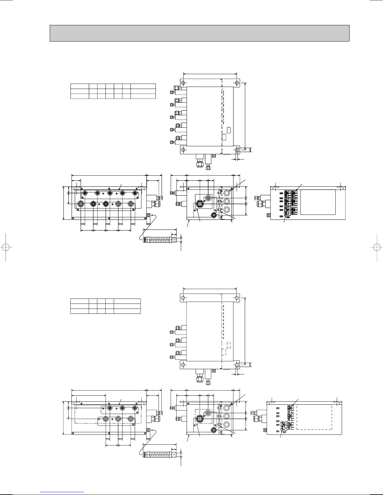
6-2. BRANCH BOX UNIT
TB2B
TB3D
TB3E
TB3ATB3B
TB3C
SUSPENSION BOLT : W3/8 (M10)
REFRIGERANT PIPE FLARED CONNECTION (inch)
DRAIN HOSE SIZE : O.D. 20 (VP-16)
LIQUID PIPE
GAS PIPE
ABCDE
TO OUTDOOR UNIT
1/4 1/4 1/4 1/4 1/4 3/8
1/2 5/8
3/8 3/8 3/8 3/8
SUSPENSION BOLT PITCH
320
402
24
SUSPENSION BOLT PITCH
12
95 280
39
61
79
50
34
3-ELECTRIC WIRE INLET
70
35
68
3-WIRE BAND
ELECTRIC COVER
TO OUTDOOR UNIT
SERVICE PANEL
(for LEV, THERMISTOR)
TERMINAL BLOCK
TO INDOOR UNIT
TERMINAL BLOCK
TO OUTDOOR UNIT
TO INDOOR UNIT
55
198
65
39
25 25 25 25 25
21
75 75 75 75
E
DC
B
A
E
D
C
B
A
91
73
200
23
[20
DRAIN PIPE CONNECTION
(VP-16)
FLEXIBLE DRAIN HOSE
(ACCESSORY)
450
SUSPENSION BOLT : W3/8 (M10)
REFRIGERANT PIPE FLARED CONNECTION (inch)
DRAIN HOSE SIZE : O.D. 20 (VP-16)
LIQUID PIPE
GAS PIPE
ABC
TO OUTDOOR UNIT
1/4 1/4 1/4 3/8
5/8
3/8 3/8 3/8
3-ELECTRIC WIRE INLET
3-WIRE BAND
ELECTRIC COVER
TO OUTDOOR UNIT
SERVICE PANEL
(for LEV, THERMISTOR)
TERMINAL BLOCK
TO INDOOR UNIT
TERMINAL BLOCK
TO OUTDOOR UNIT
TO INDOOR UNIT
DRAIN PIPE CONNECTION
(VP-16)
FLEXIBLE DRAIN HOSE
(ACCESSORY)
SUSPENSION BOLT PITCH
SUSPENSION BOLT PITCH
320
402
24
12
TB3C
TB2B
TB3B TB3A
95
61
79 50 34
39
280
703568
205
198
65
39
25 25 25
21
75 75
91
73
200
23
[20
C
B
A
C
B
A
450
PAC-AK50BC
unit : mm
PAC-AK30BC
33
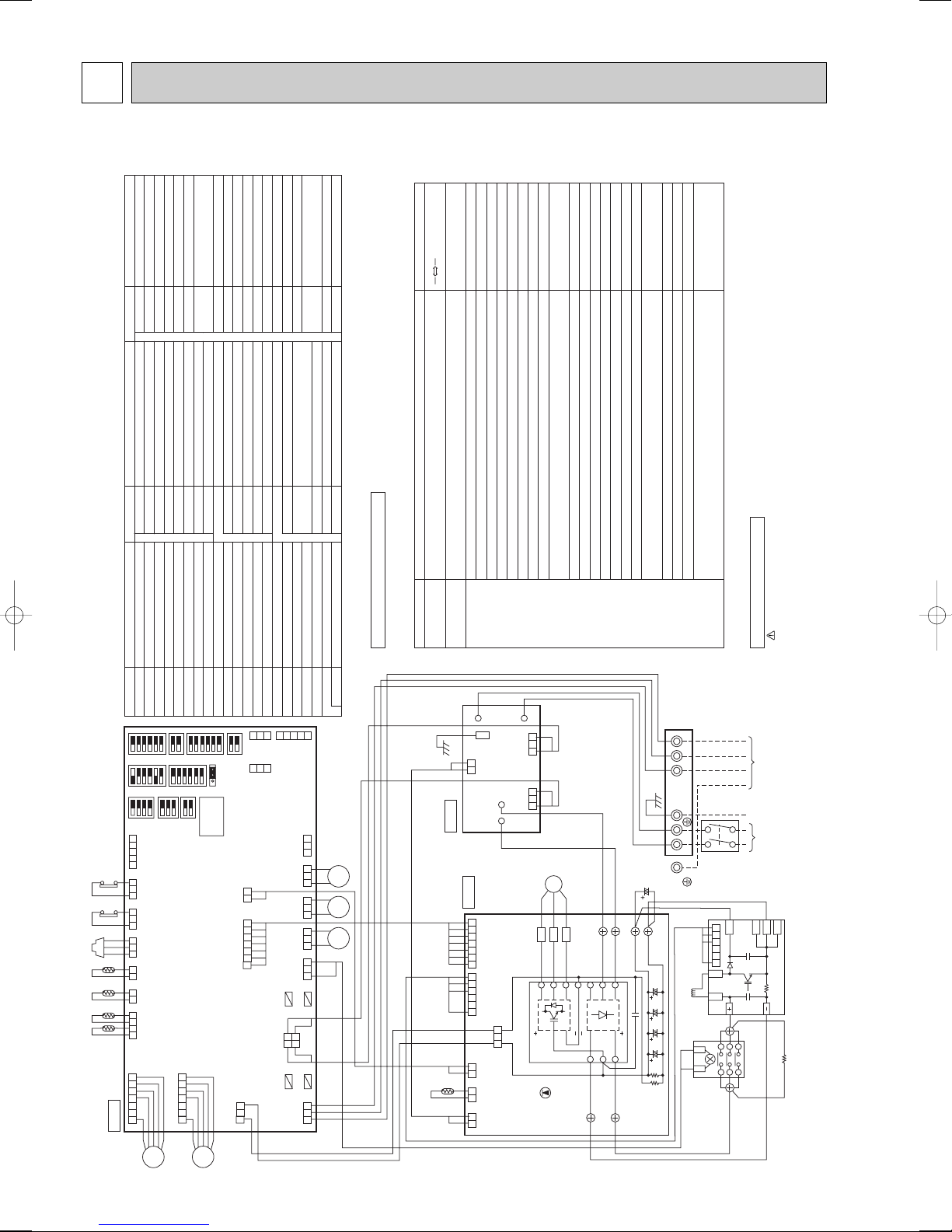
7 WIRING DIAGRAM
1
C. B.
MF1
4 5 6 7
CNF1
(WHT)
CN2
(WHT )
CN4
(WHT )
CN3S
(WHT )
CNDM
(WHT )
CN51
(WHT )
CNAC
(WHT)
TH7/6
(RED)
TH3
(WHT)
1 2 1 2
TH4
(WHT)
1 23 4
63HS
(WHT)
1 2 3
63H
(YLW)
3 1
63L
(RED)
3 1
CNIT
(RED)
1 2 3 54
TH7TH6 TH3 TH4 63HS 63H 63L
1
MF2
4 5 6 7
CNF2
(WHT)
CNDC
(PNK)
CNS
(WHT)
3 1
3 2 1
52C
(BLK)
3 1
21S4
(GRN)
3 1
SV2
(BLU)
3 1
SV1
(GRY)
3 1
SS
(WHT)
3 1
FUSE2
FUSE1
FUSE3
FUSE4
21S4 SV2 SV1
1 2
3 4
7 6 5 4 3 2 1
5 4 3 2 1 3 2 1
3 2 1
2 1
CNAF
(WHT )
CNDC
(PNK)
CN2
(WHT )
CN5
(RED)
7 6 5 4 3 2 1
2 1
CN3
(WHT)
2 1
CN4
(WHT)
2 1
6 5 4 3 2 1
13
TH8
IGBT
LED1
DCL
TB1
NO FUSE
BREAKER
40 A
BRANCH
BOX
POWER SUPPLY
~/N
220/230/240V 50Hz
220V 60Hz
CE
L N S1 S2 S3
ACTM
RS
52C
SCR-N1
SCR-P1 SCR-R
SCR-P2
SCR-N2
SCR-S
N. F.
P. B.
MC
CNAC2
(RED)
3 1
CNAC1
(WHT)
3 1
LI
NI
L0 N0
CN5
(RED)
2 1
EI
W
V
U
P
N1
N2
I
6 5 4 3 2 1
L1
L2
SW5
SW6SW1CN31
SW7SW2
SW8SW4
SW9SW10
7SEG LED
88
SYMBOL SYMBOL SYMBOLNAME NAME NAME
TB1MCMF1, MF2
21S4
SV1
SV2
63HS
63L
TH3
TH4
TH6
TH7
TH8
DCL
52CRSACTM
CE
P. B
63H
Terminal Block (Power Supply, Branch)
Motor for Compressor
Fan Motors
Solenoid Valve (Four-Way Valve)
Solenoid Valve (Hot Gas Bypass)
Solenoid Valve (Returning oil Bypass )
High pressure Sensor
High pressure Switch
Low pressure Switch
Thermistor (Outdoor Pipe)
Thermistor (Discharge)
Thermistor (Outdoor2 - Phase Pipe)
Thermistor (Outdoor)
Thermistor (Heatsink)
Reactor
52C Relay
Rush Current Protect Resistor
Active Filter Module
Main Smoothing Capacitor
Power Circuit Board
SC - R / S
SC - P1, P2
SC - N1, N2
CN2 ~ 5
CNDC
CNAF
IGBT
LED1
LI / LO
NI / NOEICNAC1 / 2
CN5
FUSE1 ~ 4
SW1
SW2
SW4
Screw Type Terminal (L / N - Phase)
Screw Type Terminal (DC Voltage)
Screw Type Terminal (DC Voltage)
Connector
Connector
Connector
Converter, Inverter
Light Emitting Diodes (Inverter Control Status)
Noise Filter Circuit Board
Connection Lead (L - Phase)
Connection Lead (N - Phase)
Connection Terminal (Ground)
Connector
Connector
Controller Circuit Board
Fuse (6. 3A)
Switch (Forced Defrost, Error History
Record Reset)
Switch (Self Diagnosis Switch)
Switch (Test Operation )
Connection Terminal (U / V / W - Phase)
U / V / W
SW5
Switch (Function Switch)
SW6
SW7
SW8
SW9
SW10
CN31
LED
CNAC
CNDC
CNS
CNF1
CNF2SSSV1
SV2
CN3S
CNDM
CN51
CNIT
Switch (Model Select)
Switch (Function Setup)
Switch
Switch (Function for option)
Switch (Function for option)
Connector
Light Emitting Diodes
(Operation Inspection Indicators)
Connector
Connector
Connector
Connector
Connector
Connector (Connection for Option)
Connector
Connector
Connector (Connection for Option)
Connector <Connected for Option
(Contact Input)>
Connector (Connection for Option)
Connector (Connection for Option)
N. F.
C. B.
Power turned on
Details
●
WARNING: When the main supply is turned off, the voltage [340 V] in the main capacitor will drop to 20 V in approx.2 minutes
(input voltage : 240 V). When servicing, make sure that LED on the outdoor circuit board gose out, and then wait for at least 1 minute.
● Components other than the outdoor board may be faulty : Check and take corrective action, referring to the service manual.
Do not replace the outdoor board without checking.
Cautions when Servicing
LED on the controller board display the operation and inspection status as follows.
If LED does not light, it indicates that no power is supplied to the board:
Operation / Inspection Display
Normal status
Faulty status
(blinking)
Code
(blinks)
Operation status display,
such as C5. H7
F3F9EA, Eb, EC
E6~E9
E0, E3~E5
EE, EFEdU2U7U1ULU6UFUHUPU3U4U5U8U9
PA
Connector (63H) open, connector (63L) open
At Ieast 2 connectors open
Incorrect wiring in indoor / outdoor unit connection
Indoor / outdoor unit communication error
Remote controller communication error
Combination error, undefined error
Serial communication error
Discharge temperature fault
Low-discharge superheating fault, Erroneous connection of refrigerant pipes or
the connecting wires
High pressure fault (63H operates)
Low pressure fault (63L operates)
Abnormality of power modules
Compressor overcurrent shutoff (Start up locked)
Current sensor fault (P. B.)
Compressor overcurrent shutoff fault
Discharge pipe/compressor thermistor (TH4) open or short-circuit
Outdoor unit thermistors (TH3, TH6, TH7, and TH8), 63HS, and branch box
thermistors open or short-circuit
Heatsink temperature fault
Abnormality in outdoor fan motor
Voltage fault, current sensor fault (N. F.)
Forced compressor stop
(Overlap malfunction of drain pump in indoor unit
and linear expansion valve in branch box)
WHT
BLK
BLK BLK
WHT
WHT
WHT
RED
RED
BLU
BLU
RED
RED
RED
YLW ORN
BRN
RED
GRN
/YLW
7-1. OUTDOOR UNIT
MXZ-8A140VA
34
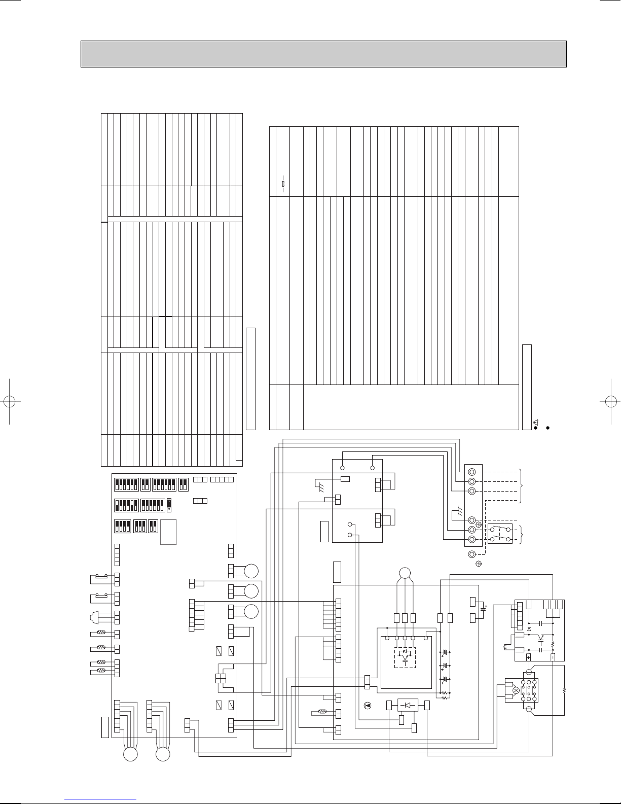
1
C. B.
MF1
4 5 6 7
CNF1
(WHT)
CN2
(WHT)
CN4
(WHT)
CN3S
(WHT)
CNDM
(WHT)
CN51
(WHT)
CNAC
(WHT)
TH7/6
(RED)
TH3
(WHT)
1 2 1 2
TH4
(WHT)
1 23 4
63HS
(WHT)
1 2 3
63H
(YLW)
3 1
63L
(RED)
3 1
CNIT
(RED)
1 2 3 54
TH7TH6 TH3 TH4 63HS 63H 63L
1
MF2
4 5 6 7
CNF2
(WHT)
CNDC
(PNK)
CNS
(WHT)
3 1
3 2 1
52C
(BLK)
3 1
21S4
(GRN)
3 1
SV2
(BLU)
3 1
SV1
(GRY)
3 1
SS
(WHT)
3 1
FUSE2
FUSE1
FUSE3
FUSE4
21S4
SV2 SV1
1 2
3 4
7 6 5 4 3 2 1
5 4 3 2 1 3 2 1
3 2 1
2 1
CNAF
(WHT)
CNDC
(PNK)
CN2
(WHT)
CN5
(RED)
7 6 5 4 3 2 1
2 1
CN3
(WHT)
2 1
CN4
(WHT)
2 1
6 5 4 3 2 1
13
TH8
IPM
LED1
WHT
BLK BLK
ACTMRS
RED
WHT
WHT
BLK
RED
RED
TABP1
TABP2
TABN1
TABN2
TABN TABP
TABS
TABT
BLU
WHT
DCL
TB1
NO FUSE
BREAKER
40 A
BRANCH
BOX
POWER SUPPLY
~/N
220/230/240V 50Hz
220V 60Hz
CE
L N S1 S2 S3
52C
N. F.
P. B.
MC
CNAC2
(RED)
3 1
CNAC1
(WHT)
3 1
LI
NI
L0 N0
CN5
(RED)
2 1
EI
W
V
U
P
N1
N2
I
6 5 4 3 2 1
L1
L2
SW5
SW6SW1CN31
SW7SW2
SW8SW4
SW9SW10
7SEG LED
88
SYMBOL SYMBOL SYMBOLNAME NAME NAME
TB1MCMF1, MF2
21S4
SV1
SV2
63HS
63L
TH3
TH4
TH6
TH7
TH8
DCL
52CRSACTM
CE
P. B
63H
Terminal Block (Power Supply, Branch)
Motor for Compressor
Fan Motors
Solenoid Valve (Four-Way Valve)
Solenoid Valve (Hot Gas Bypass)
Solenoid Valve (Returning oil Bypass)
High pressure Sensor
High pressure Switch
Low pressure Switch
Thermistor (Outdoor Pipe)
Thermistor (Discharge)
Thermistor (Outdoor2 - Phase Pipe)
Thermistor (Outdoor)
Thermistor (Heatsink)
Reactor
52C Relay
Rush Current Protect Resistor
Active Filter Module
Main Smoothing Capacitor
Power Circuit Board
TAB - S / T
TAB-P/P1/P2
TAB-N/N1/N2
CN2 ~ 5
CNDC
CNAF
IPM
LED1
LI / LO
NI / NOEICNAC1 / 2
CN5
FUSE1 ~ 4
SW1
SW2
SW4
Terminal (L / N - Phase)
Terminal (DC Voltage)
Terminal (DC Voltage)
Connector
Connector
Connector
Inverter
Light Emitting Diodes (Inverter Control Status)
Noise Filter Circuit Board
Connection Lead (L - Phase)
Connection Lead (N - Phase)
Connection Terminal (Ground)
Connector
Connector
Controller Circuit Board
Fuse (6.3A)
Switch (Forced Defrost, Error History
Record Reset)
Switch (Self Diagnosis Switch)
Switch (Test Operation )
Connection Terminal (U / V / W - Phase)
U / V / W
SW5
Switch (Function Switch)
SW6
SW7
SW8
SW9
SW10
CN31
LED
CNAC
CNDC
CNS
CNF1
CNF2SSSV1
SV2
CN3S
CNDM
CN51
CNIT
Switch (Model Select)
Switch (Function Setup)
Switch
Switch (Function for option)
Switch (Function for option)
Connector
Light Emitting Diodes
(Operation Inspection Indicators)
Connector
Connector
Connector
Connector
Connector
Connector (Connection for Option)
Connector
Connector
Connector (Connection for Option)
Connector <Connected for Option
(Contact Input)>
Connector (Connection for Option)
Connector (Connection for Option)
N. F.
C. B.
Power turned on
Details
WARNING: When the main supply is turned off, the voltage[340 V]in the main capacitor will drop to 20 V in approx.2 minutes
(input voltage : 240 V). When servicing, make sure that LED on the outdoor circuit board gose out, and then wait for at least 1 minute.
Components other than the outdoor board may be faulty : Check and take corrective action, referring to the service manual.
Do not replace the outdoor board without checking.
Cautions when Servicing
LED on the controller board display the operation and inspection status as follows.
If LED does not light, it indicates that no power is supplied to the board:
Operation / Inspection Display
Normal status
Faulty status
(blinking)
Code
(blinks)
Operation status display,
such as C5. H7
F3F5F9E8E9EAEbEcE0 E7
EE, EFEdU2U7U1ULU6UFUHUPU3U4U5U8U9
PA
63L connector (red) is open.
63H connector (yellow) is open.
2 connectors (63H/63L) are open.
Branch box/outdoor communication error (Signal receiving error) (Outdoor unit)
Indoor/branch box communication error (Signal receiving error) (Branch box)
Branch box/outdoor communication error (Transmitting error) (Outdoor unit)
Indoor/branch box communication error (Transmitting error) (Branch box)
Miswiring of indoor-branch box / branch box-outdoor unit connecting wire.
Too many indoor units / branch box are in the system.
Miswiring of indoor-branch box/branch box-outdoor unit connecting wire (converse wiring or disconnection)
Startup time over
Communication error except for outdoor unit
Combination error, undefined error
Serial communication error
Discharge temperature fault
Low-discharge superheating fault, Erroneous connection of refrigerant pipes or
the connecting wires
High pressure fault (63H operates)
Low pressure fault (63L operates)
Abnormality of power modules
Compressor overcurrent shutoff (Start up locked)
Current sensor fault (P. B.)
Compressor overcurrent shutoff fault
Discharge pipe/compressor thermistor (TH4) open or short-circuit
Outdoor unit thermistors (TH3, TH6, TH7, and TH8), 63HS, and branch box
thermistors open or short-circuit
Heatsink temperature fault
Abnormality in outdoor fan motor
Voltage fault, current sensor fault (N. F.)
Forced compressor stop
(Overlap malfunction of drain pump in indoor unit
and linear expansion valve in branch box)
MXZ-8A140VA1 MXZ-8A140VA2
35

MXZ-8A140VA3
Power turned on
LED on the controller board display the operation and inspection status as follows.
If LED does not light, it indicates that no power is supplied to the board:
Operation / Inspection Display
Normal status
Faulty status
(blinking)
Details
• WARNING:When the main supply is turned off, the voltage[340 V]in the main capacitor will drop to 20 V in approx.2 minutes
(input voltage : 240 V). When servicing, make sure that LED on the outdoor circuit board goes out, and then wait for at least
1 minute.
• Components other than the outdoor board may be faulty : Check and take corrective action, referring to the service manual.
Do not replace the outdoor board without checking.
Cautions when Servicing
Code
(blinks)
Operation status display,
such as C5. H7
F3F5F9E8E9
EAEbEc
E0 - E7
EE, EFEdU2U7U1ULU6UFUHUPU3U4U5U8U9
PA
63L connector (red) is open.
63H connector (yellow) is open.
2 connectors (63H/63L) are open.
Branch box/outdoor communication error (Signal receiving error)(Outdoor unit)
Indoor/branch box communication error (Signal receiving error)(Branch box)
Branch box/outdoor communication error (Transmitting error)(Outdoor unit)
Indoor/branch box communication error (Transmitting error)(Branch box)
· Miswiring of indoor-branch box / branch box-outdoor unit connecting wire.
· Too many indoor units / branch box are in the system.
Miswiring of indoor-branch box/branch box-outdoor unit connecting wire (converse wiring or disconnection)
Startup time over
Communication error except for outdoor unit
Combination errer, undefined error
Serial communication error
Discharge temperature fault
Low-discharge superheating fault, Erroneous connection of refrigerant pipes or
the connecting wires
High pressure fault (63H operates)
Low pressure fault (63L operates)
Abnormality of power modules
Compressor over current shutoff (Start up locked)
Current sensor fault (P. B.)
Compressor overcurrent shutoff fault
Discharge pipe/compressor thermistor (TH4) open or short-circuit
Outdoor unit thermistors (TH3, TH6, TH7, and TH8), 63HS, and branch dox
thermistors open or short-circuit
Heatsink temperature fault
Abnormality in outdoor fan motor
Voltage fault, current sensor fault (N. F.)
Forced compressor stop
(Overlap malfunction of drain pump in indoor unit
and linear expansion valve in branch box)
SYMBOL SYMBOL SYMBOLNAME NAME NAME
TB1MCMF1, MF2
21S4
SV1,SV2
63HS
63L
TH3
TH4
TH6
TH7
TH8
DCL
52C
ACTM
CB
P. B.
63H
Terminal Block
(Power Supply, Branch Box)
Motor for Compressor
Fan Motors
Solenoid Valve (Four-Way Valve)
Solenoid Valve (Bypass Valve )
High Pressure Sensor
High Pressure Switch
Low Pressure Switch
Thermistor(Outdoor Pipe)
Thermistor(Discharge)
Thermistor(Outdoor 2 - Phase Pipe)
Thermistor(Outdoor)
Thermistor(Radiator Panel)
Reactor
52C Relay
Active Filter Module
Main Smoothing Capacitor
Power Circuit Board
TABS / T
TABP1/P2/P
TABN1/N2/N
DS2, DS3
IPM
LI / LO
NI / NO
EI, E2
F1
~
F4
X51
~
X55
SW1
SW2
SW4
Connection Terminal (L / N - Phase)
Connection Terminal (DC Voltage)
Connection Terminal (DC Voltage)
Diode Bridge
Power Module
Noise Filter Circuit Board
Connection Terminal (L - Phase)
Connection Terminal (N - Phase)
Connection Terminal (Ground)
Controller Circuit Board
Fuse (T6.3AL250V)
Relay
Switch (Forced Defrost, Defect History
Record Reset)
Switch (Self Diagnosis Switch)
Switch (Test Operation )
Connection Terminal(U / V / W - Phase)
TABU / V / W
SW5
Switch (Function Switch)
SW6
SW7
SW8
SW9SSCN3S
CNIT
Switch (Model Select)
Switch (Function Setup)
Switch (Function Setup)
Switch (Function Setup)
CN31 Connector
LED
Light Emitting Diode
(Operation Inspection Indicators)
Connector(Connection for Option)
Connector(Connection for Option)
CNDM
Connector<Connected for Option
(Contact Input)>
CN51
Connector(Connection for Option)
Connector(Connection for Option)
N. F.
C. B.
MODEL
MXZ-8A140VA
SW6
ON
OFF
12345678
MS
3~
MF1
1
3
1
7
CNF1
(WHT)
TRANS
MS
3~
MF2
17
CNF2
(WHT)
CNDC
(PNK)
2
4
11221
TH7/6
(RED)
TH3
(WHT)
TH4
(WHT)
TH7
t
°
t
°
t
°
t
°
TH6 TH3 TH4
3
1
63HS
63HS
(WHT)
63L
(RED)
31
63L
63H
(YLW)
31
63H
17
31
CNS
(WHT)
2
7
CN2
(WHT)
F3
12
1313
CNAC
(WHT)
CN4
(WHT)
1
2
3
4
F4
F2
F1
21S4
(GRN)
SV2
(BLU)
X52
X55
21S4 SV2
13
SV1
(GRY)
X54
SV1
13
SS
(WHT)
X51
114
CNM
(WHT)
LED1
12
2
CN52C
(RED)
1
5
CNIT
(RED)
1
5
CN51
(WHT)
1
3
CNDM
(WHT)
1
3
CN3S
(WHT)
SW8 SW5
SW1
CN31
SW6
SW9SW2 SW7
SW4
P. B.
7
1
12121
2
7
6
2
2
TABN
TABP
CN2
(WHT)
4
1
CNAF
(WHT)
CN4
(WHT)
CN5
(RED)
CN3
(WHT)
TH8
t
°
WHT
RED
CB
C. B.
N. F.
BLU
S1NL
S2 S3
YLW
ORN
GRN / YLW
BRN
RED
TB1
NO FUSE
BREAKER
40 A
BRANCH BOX
POWER SUPPLY
~/N
220/230/240V 50Hz
220V 60Hz
DCL
ACTM
L1 L2
N2IoN1
P
4
16
RED
BLK
BLK
RED
WHT
WHT
IPM
TABV
TABW
TABN1
BLK
TABN2
TABU
TABP2
U
V
W
MC
RED
RED
WHT
WHT
BLK
MS
3~
1
3
2
CNDC
(PNK)
U
DS2
DS3
TABS
TABP1
TABT
RED
BLU
WHT
WHT
LO
52C
NO
LI
NI
CN5
(RED)
CNAC2
(RED)
CNAC1
(WHT)
CN52C
(BLK)
2
2
1
3
E2
EI
U
U
1
2
1
2
3
1
BLU
36

7-2. BRANCH BOX : PAC-AK50BC PAC-AK30BC
5
3
1
YLW
TB3E
(PAC - AK50BC only)
WSetup of SW1
Make it the same setup as former
one when exchanging PCB.
TO INDOOR
UNIT -E
(PAC - AK50BC only)
(
PAC - AK50BC only
)
TO INDOOR
UNIT -D
TO INDOOR
UNIT -C
TO INDOOR
UNIT -B
TO INDOOR
UNIT -A
TO OUTDOOR
UNIT
ORN
BRN
TB3E
(GRN)
5
3
1
YLW
ORN
BRN
TB3D
(BLK)
5
3
1
YLW
ORN
BRN
TB3C
(BLU)
5
3
1
YLW
ORN
BRN
TB3B
(RED)
LEV-A
(WHT)
5
3
1
1
2
1
6
YLW
ORN
BRN
TB3A
(WHT)
1
3
YLW
F1
TB1
ORN
BRN
CN3C
(BLU)
3
1
CND
(ORN)
1 2 3 4 5 6 7
8 9
1011 1213 14
CNM
SW1 W
LED1 LED2 LED3 LED4 LED5
1
2
1
2
1
2
1
2
6
LEV-A
LEV-B
(RED)
1
6
6
LEV-B
LEV-C
(BLU)
1
6
6
LEV-C
LEV-D
(BLK)
1
6
6
LEV-D
LEV-E
(GRN)
TH-A
(WHT)
TH-B
(RED)
TH-C
(BLU)
TH-D
(BLK)
TH-E
(GRN)
1
6
6
LEV-E
TH-A
TH-B
TH-C
TH-D
TH-E
S1
S2
S3
TB3D
S1
S2
S3
TB3C
S1
S2
S3
TB3B
S1
S2
S3
TB3A
S1
S2
S3
TB2B
S1
S2
S3
Note : " PAC - AK30 . 50BC " is only for R410A.
Note
1. At servicing for outdoor unit, always follow the wiring diagram of Outdoor unit.
2. Symbols used in wiring diagram above are, : terminal block, : connector.
(Combination of indoor units)
Fill out the location of combined indoor units with model name in each
blank below because it is necessary for service and maintenance.
SYMBOL
B.C
F1
<
B.C
>
SW1<B.C
>
CNM<B.C
>
LED1~5< B.C>
TB3A
TB3B
TB3C
TB3D
TB3E
LEV-A~E
TH-A~E
TB2B
Branch box controller board
Fuse 250V 6.3A
Switch for service
Connector
Light emitting diode
Terminal block / To indoor unit - A
Terminal block / To indoor unit - B
Terminal block / To indoor unit - C
Terminal block / To indoor unit - D
Terminal block / To indoor unit - E
Linear expansion valve
Thermistor
Pipe temp.detection / Gas
(
0 : / 15k', 25 : / 5.4k'
)
Terminal block / To outdoor unit
NAME
Indoor unit - A Indoor unit - B Indoor unit - C Indoor unit - D Indoor unit - E
B.C
(PAC - AK50BC only)
ON
OFF
37

8
A
BB BBB
Branch box
A
A
A
BB
BBB
2 branches pipe (joint)
: optional parts
Branch box #1
Branch box #2
Thermistor TH6
(Pipe temperature : condenser)
Thermistor TH7
(Outdoor temperature)
Thermistor TH3
(Pipe temperature : liquid)
Strainer
#100
Strainer
#100
Oil separator
Low
pressure
switch
63L
High
pressure
switch
63H
Compressor
Thermistor TH4
(Discharge temperature)
Thermistor TH8
(Fin temperature)
Strainer
#100
Strainer
#50
Check valve
(High Pressure)
Check valve
(Low Pressure)
Capillary
tube3
Capillary
tube4
Capillary
tube2
Capillary
tube1
E
D
C
B
A
Strainer
#100
Condenser / evaporator
temperature thermistor
(TH5 or RT12)
Pipe temperature
thermistor / liquid
(TH2 or RT13)
Strainer
#100
Indoor units Branch box Outdoor unit
Thermistor (TH-A~E)
(Gas pipe temperature)
LEV A~E
(Linear expansion valve)
Room temperature
thermistor (TH1 or RT11)
Service port
Service port
Ball valve
Stop valve
Bypass valve(SV2)
Bypass valve (SV1)
High pressure sensor
discharge pressure sensor
63HS
Accumulator
4-way valve
Distributor
with Strainer
Refrigerant flow in cooling
Refrigerant flow in heating
Outdoor unit
MXZ-8A140VA
MXZ-8A140VA1
MXZ-8A140VA2
MXZ-8A140VA3
PAC-AK50BC
PAC-AK30BC
Branch box
Capillary tube 1
(For return of oil
from oil separator)
Capillary tube 2
(For SV2)
Capillary tube 3
ahead of LEV
(in cooling mode)
Capillary tube 4
behind LEV
(in cooling mode)
[2.5 o [0.8 o L1000
[4 o [2.4 o L250
([4 o [2.4 o L140) o 5([4 o [2.2 o L130) o 5
([4 o [2.4 o L140) o 3([4 o [2.2 o L130) o 3
unit : mm
NECESSARY CONDITIONS FOR SYSTEM CONSTRUCTION
REFRIGERANT SYSTEM DIAGRAM
Piping connection size
A
Liquid (mm)
Gas (mm)
■ In case of using 1-branch box
Flare connection employed (No. brazing)
■ In case of using 2-branch boxes
{15.88
{9.52
The pipe connection size differs according to the type and capacity of indoor units.
Match the piping connection size of branch box with indoor unit.
If the piping connection size of branch box does not match the piping connection
size of indoor unit, use optional different-diameter (deformed) joints to the branch
box side. (Connect deformed joint directly to the branch box side.)
B
■ installation procedure (2 branch pipe (joint))
Refer to the installation manuals of MSDD-50AR-E and MSDD-50BR-E.
38
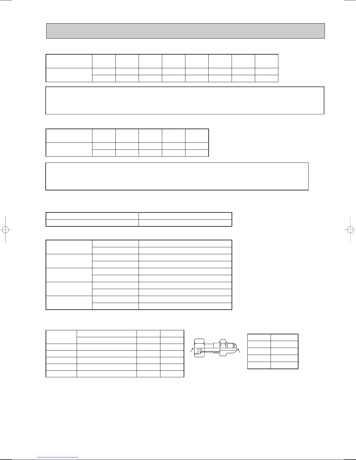
■ Pipe size (Branch box-Indoor unit) *Case of M series or S series Indoor unit
Indoor unit
type
Pipe size
(mm)
(kW)
Liquid
Gas
35
[6.35
[12.7
50
[6.35
[12.7
60
[9.52
[15.88
71
[9.52
[15.88
For liquid
For gas
[9.52mm
[15.88mm
A UNIT
B UNIT
C UNIT
D UNIT
E UNIT
Liquid pipe
Gas pipe
Liquid pipe
Gas pipe
Liquid pipe
Gas pipe
Liquid pipe
Gas pipe
Liquid pipe
Gas pipe
[6.35 mm
[9.52 mm
[6.35 mm
[9.52 mm
[6.35 mm
[9.52 mm
[6.35 mm
[9.52 mm
[6.35 mm
[12.7 mm
w 3- branch type is only for A, B, and C unit.
w
w
w
[6.35mm
[9.52mm
[12.7mm
[15.88mm
[19.05mm
Conversion formula
1/4 inch
3/8 inch
1/2 inch
5/8 inch
3/4 inch
(1) Valve size for outdoor unit
(2) Valve size for branch unit
Different-diameter joint (optional parts) (Fig.7-1)
Fig.7-1
MAC-A454JP
MAC-A455JP
MAC-A456JP
PAC-493PI
PAC-SG76RJ-E
{9.52 ➝ {12.7
{12.7 ➝ {9.52
{12.7 ➝ {15.88
{6.35 ➝ {9.52
{9.52 ➝ {15.88
{9.52
{12.7
{12.7
{6.35
{9.52
{12.7
{9.52
{15.88
{9.52
{15.88
Connected pipes diameter
mm
Diameter AmmDiameter B
mm
Model name
AB
Indoor unit
type
Pipe size
(mm)
When using 60 type indoor unit of MEXZ series, use the flare nut in the indoor unit accessory for the gas side
connecting of indoor unit.
Do not use the flare nut (gas side) attached to the indoor unit. If it is used, a gas leakage or even a pipe extraction
may occur.
■ Pipe size (Branch box-Indoor unit) *Case of P series Indoor unit
When using 35, 50 type indoor unit of P series, use the flare nut (for R410A) attached to the indoor unit.
Do not use the flare nut (for R407C) in the indoor unit accessory. If it is used, a gas leakage or even a pipe
extraction may occur.
(kW)
Liquid
Gas
22
[6.35
[9.52
25
[6.35
[9.52
35
[6.35
[9.52
50
[6.35
[12.7
60
[6.35
[15.88 w
71
[9.52
[15.88
80
[9.52
[15.88
39
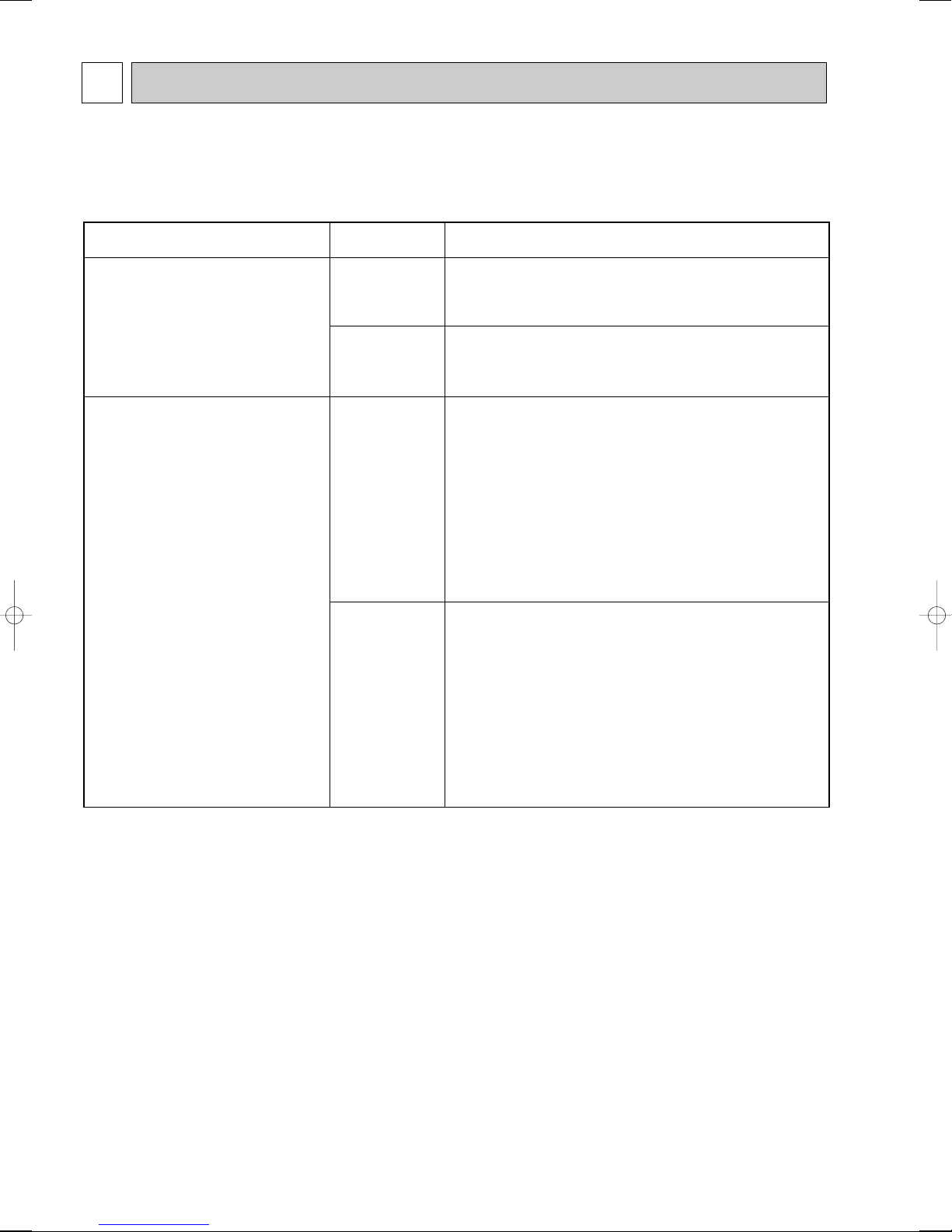
9 TROUBLESHOOTING
Unit conditions at service
Error code
Actions to be taken for service (summary)
The trouble has recurred.
Displayed
Not displayed
Judge what is wrong and take a corrective action according
to “9-3. SELF-DIAGNOSIS ACTION TABLE”.
Conduct trouble shooting and ascertain the cause of the
trouble according to “9-4. TROUBLESHOOTING
BY INFERIOR PHENOMENA”.
The trouble is not reoccurring.
Logged
Not logged
1Consider the temporary defects such as the work of
protection devices in the refrigerant circuit including
compressor, poor connection of wiring, noise and etc.
Re-check the symptom, and check the installation
environment, refrigerant amount, weather when the
trouble occurred, matters related to wiring and etc.
2Reset error code logs and restart the unit after finishing
service.
3There is no abnormality concerning of parts such as
electrical component, controller board, remote controller
and etc.
1Re-check the abnormal symptom.
2Conduct trouble shooting and ascertain the cause of the
trouble
according to “9-4. TROUBLESHOOTING
BY INFERIOR PHENOMENA
”.
3Continue to operate unit for the time being if the cause
is not ascertained.
4There is no abnormality concerning of parts such as
electrical component, controller board, remote controller
and etc.
9-1. TROUBLESHOOTING
<Error code display by self-diagnosis and actions to be taken for service (summary)>
Present and past error codes are logged and displayed on the wired remote controller and control board of outdoor unit.
Actions to be taken for service, which depends on whether or not the trouble is reoccurring at service, are summarized in the
table below. Check the contents below before investigating details.
40

9-2. CHECK POINTS FOR TEST RUN
9-2-1. Before test run
● Turn on the main power switch more than 12 hours before starting operation.Starting operation just after turning on the
power switch can severely damage the internal parts. Keep the main power switch turned on during the operation season.
● After completing installation and the wiring and piping of the indoor and outdoor units, check for refrigerant leakage,
looseness in the power supply or control wiring, wrong polarity, and no disconnection of one phase in the supply.
● Use a 500-volt M-ohm tester to check that the resistance between the power supply terminals and ground is at least 1 M".
● Do not carry out this test on the control wiring (low voltage circuit) terminals.
..
Warning: Do not use the air conditioner if the insulation resistance is less than 1 M"".
Insulation resistance
After installation or after the power source to the unit has been cut for an extended period, the insulation resistance will drop
below 1 M" due to refrigerant accumulating in the compressor. This is not a malfunction. Perform the following procedures.
1.Remove the wires from the compressor and measure the insulation resistance of the compressor.
2.If the insulation resistance is below 1 M", the compressor is faulty or the resistance dropped due to the accumulation of
refrigerant in the compressor.
3.After connecting the wires to the compressor, the compressor will start to warm up after power is supplied. After supplying
power for the times indicated below, measure the insulation resistance again.
• The insulation resistance drops due to accumulation of refrigerant in the compressor. The resistance will rise above 1M"
after the compressor is warmed up for 4 hours. (The time necessary to warm up the compressor varies according to
atmospheric conditions and refrigerant accumulation.)
• To operate the compressor with refrigerant accumulated in the compressor, the compressor must be warmed up at least
12 hours to prevent breakdown.
4. If the insulation resistance rises above 1 M", the compressor is not faulty.
..
Caution:
• The compressor will not operate unless the power supply phase connection is correct.
• Turn on the power at least 12 hours before starting operation.
Staring operation immediately after turning on the main power switch can result in severe damage to internal parts.
Keep the power switch turned on during the operational season.
● The followings must be checked as well.
• The outdoor unit is not faulty. LED on the control board of the outdoor unit flashes when the outdoor unit is faulty.
• Both the gas and liquid stop valves are completely open.
9-2-2. Test run
(1) Using remote controller
Refer to the indoor unit installation manual.
• Be sure to perform the test run for each indoor unit. Make sure each indoor unit operates properly following the installation
manual attached to the unit.
• If you perform the test run for all indoor units at once, you cannot detect any erroneous connection, if any, of the refrigerant
pipes and the connecting wires.
* The compressor operation is not available for 3 minutes at least after the power is supplied.
• The compressor can emit noise just after turn on the power supply or in case of low outside air temperature.
About the restart protective mechanism
Once the compressor stops, the restart preventive device operates so the compressor will not operate for 3 minutes to protect
the air conditioner.
41

ON
SW4
12
A Stop
B Cooling
C Operation
D Heating
A
CD
B
(Initial setting)
(2) Using SW4 in outdoor unit
In case of the test run from outdoor unit, all indoor units operate. Therefore, you cannot detect any erroneous connection of refrigerant pipes and the connecting wires. If it aims at detection of any erroneous connection, be sure to
carry out the test run from remote controller with reference to "(1) Using remote controller."
SW4-1
SW4-2
SW4-1
SW4-2
w After performing the test run, set SW4-1 to OFF.
• Afew seconds after the compressor starts, a clanging noise may be heard from the inside of the outdoor unit. The noise is
coming from the check valve due to the small difference in pressure in the pipes. The unit is not faulty.
The test run operation mode cannot be changed by DIP switch SW4-2 during the test run. To change the test run
operation mode during the test run, stop the test run by DIP switch SW4-1. After changing the test run operation
mode, resume the test run by switch SW4-1.
ON
OFF
ON
ON
Cooling operation
Heating operation
When a test run is started by “Using SW4 in outdoor unit”, even if it carries out stop instructions by
remote controller, outdoor unit does not stop. A test run is not ended.
In this case, please set SW4 in outdoor unit to off.
• After power is supplied or after an operation stop for a while, a small clicking noise may be heard from the inside
of the branch box. The electronic expansion valve is opening and closing. The unit is not faulty.
NOTE:Be sure to wait at least 3 minutes after turning on the power supply before setting SW4-1and SW4-2.
If the DIP switches are set before 3 minutes has elapsed, the test run may not start.
9-2-3. Test run by outdoor unit SW4
The setting of test run (ON/OFF) and its operation mode (cooling/heating) can be set by SW4 on the controller board of outdoor unit.
1Set operation mode(cooling or heating) by SW4-2.
2Start test run by setting SW4-1 to ON ( ) with the indicated operation mode of SW4-2.
3Finish test run by setting SW4-1 to OFF ( ).
• Operation mode cannot be changed by SW4-2 during test run.
Stop test run to change operation mode by SW4-1, and restart test run by SW4-1 after
the mode is changed.
• Test run automatically stops 2 hours later by 2-hour OFF timer function.
• Test run can be performed by the remote controller.
• The remote controller display of test run by outdoor unit is the same as that of test run by
remote controller.
• If test run is set with the outdoor unit, the test run is performed for all indoor units.
• The remote controller operation becomes unavailable once the test run is set with the outdoor unit.
During the test run set with the outdoor unit, operation on/off or operation mode change cannot be performed by the remote
controller, and the operation relating to the test run which is made with the outdoor unit will be prior to any other commands
from the remote controller. Set the SW4-1 to OFF ( ) to finish test run.
Emergency operation is not available for this model.
42
9-3. SELF-DIAGNOSIS ACTION TABLE
<Abnormalities detected when the power is put on>
Error Code
None —
Abnormal point and detection method
1 No voltage is supplied to termi-
2 Electric power is not charged
3 Electric power is not supplied
(Note 1) Refer to indoor unit section for code P and code E.
Case
nal block(TB1) of outdoor unit.
a) Power supply breaker is
turned off.
b) Contact failure or discon-
nection of power supply terminal
c) Open phase (L or N phase)
to power supply terminal of
outdoor power circuit board.
a) Contact failure of power
supply terminal
b) Open phase on the outdoor
power circuit board
Disconnection of connector
SC-R or SC-S
to outdoor controller circuit
board.
a) Disconnection of connector
(CNDC)
1 Check following items.
a) Power supply breaker
b) Connection of power supply terminal
c) Connection of power supply terminal
2 Check following items.
a) Connection of power supply terminal
b) Connection of terminal on outdoor power
3 Check connection of the connector (CNDC)
on the outdoor controller circuit board.
Check connection of the connector, CNDC
on the outdoor power circuit board.
Refer to 9-7.
Judgment and action
block.
(TB1)
block.
(TB1)
block.
(TB1)
circuit board.
Disconnection of connector SC-R or
SC-S
Refer to 9-7.
F3
(5202)
F5
(5201)
63L connector open
Abnormal if 63L connector circuit is open
for 3 minutes continuously after power supply
63L: Low-pressure switch
63H connector open
Abnormal if 63H connector circuit is open
for 3 minutes continuously after power supply
63H: High-pressure switch
4 Disconnection of reactor (DCL)
5 Disconnection of outdoor noise
filter circuit board or parts failure in outdoor noise filter circuit
board
6 Defective outdoor power circuit
board
7 Defective outdoor controller
circuit board
1 Disconnection or contact failure
of 63L connector on outdoor
controller circuit board
2 Disconnection or contact failure
of 63L
3 63L is working due to refriger-
ant leakage or defective parts.
4 Defective outdoor controller
circuit board
1 Disconnection or contact failure
of 63H connector on outdoor
controller circuit board
2 Disconnection or contact failure
of 63H
3 63H is working due to defective
parts.
4 Defective outdoor controller
circuit board
4 Check connection of reactor. (DCL)
Check connection of “L1” and “L2”
on the active filter module.(ACTM)
5 a) Check connection of outdoor noise filter
circuit board.
b) Replace outdoor noise filter circuit board.
Refer to 9-7.
6 Replace outdoor power circuit board.
7 Replace controller board (When items above
are checked but the units cannot be
repaired.)
1 Check connection of 63L connector on
outdoor controller circuit board.
Refer to 9-7.
2 Check the 63L side of connecting wire.
3 Check refrigerant pressure.
Charge additional refrigerant.
Check continuity by tester.
Replace the parts if the parts are defective.
4 Replace outdoor controller circuit board.
1 Check connection of 63H connector on
outdoor controller circuit board.
Refer to 9-7.
2 Check the 63H side of connecting wire.
3 Check continuity by tester.
Replace the parts if the parts are defective.
4 Replace outdoor controller circuit board.
2 connector open
Abnormal if both 63H and 63L connector
circuits are open for 3 minutes continuously after power supply
F9
(4119)
63H: High-pressure switch
63L: Low-pressure switch
1 Disconnection or contact failure
of connector (63H,63L) on
outdoor controller circuit board.
2 Disconnection or contact failure
of 63H, 63L
3 63H and 63L are working due
to defective parts.
4 Defective outdoor controller
board
43
1 Check connection of connector(63H,63L) on
outdoor controller circuit board.
Refer to 9-7.
2 Check the 63H and 63L side of connecting
wire.
3 Check continuity by tester.
Replace the parts if the parts are defective.
4 Replace outdoor controller circuit board.
Error Code
EA
(6844)
Eb
(6845)
Abnormal point and detection method Judgment and action
Indoor–branch box/branch box–outdoor
unit connector miswiring, excessive
number of units
1. Outdoor/branch box controller circuit
board can automatically check the number of connected indoor units. Abnormal
if the number cannot be checked automatically due to miswiring of indoor–
branch box/branch box–outdoor unit
connecting wire and etc. after power is
turned on for 4 minutes.
Miswiring of indoor–branch box/branch
box–outdoor unit
connecting wire (converse wiring or
disconnection)
Outdoor/branch box controller circuit board
can automatically set the unit number of
indoor units.
Abnormal if the indoor unit number can
not be set within 4 minutes after power on
because of miswiring (converse wiring or
disconnection) of indoor–branch
box/branch box–outdoor unit connecting
wire.
1 Contact failure or miswiring of
indoor/outdoor unit connecting
wire
2 Diameter or length of indoor–
branch box/branch box–outdoor unit connecting wire is out
of specified capacity.
There are 9 or more indoor
units in the system.
There are 3 or more branch
boxes in the system.
3 Defective transmitting receiving
circuit of outdoor/branch box
controller circuit board
4 Defective transmitting receiving
circuit of branch box/indoor
controller board
5 Defective branch box/indoor
power board
6 Noise has entered into power
supply or indoor–branch box
/branch box–outdoor unit
connecting wire.
1 Contact failure or miswiring of
indoor–branch box/branch box
–outdoor unit connecting wire
2 Diameter or length of indoor–
branch box/branch box–outdoor unit connecting wire is out
of specified capacity.
4 Defective transmitting receiving
circuit of outdoor/branch box
controller circuit board
5 Defective transmitting receiving
circuit of indoor/branch box
controller board
6 Defective indoor/branch box
power board
7 Noise has entered into power
supply or indoor–branch
box/branch box–outdoor unit
connecting wire.
Case
1 Check disconnection or looseness or polarity
of indoor–branch box/branch box–outdoor
unit connecting wire of indoor and outdoor
units.
2 Check diameter and length of indoor–branch
box/branch box–outdoor unit connecting wire.
Total wiring length: 55m (outdoor–branch box)
(including wiring connecting each branch box
unit and between branch box and outdoor
unit)
Also check if the connection order of flat
cable is S1, S2, S3.
If the error “EA” is detected, check the number of the indoor units and the branch box in
the system.
3~5 Turn the power off once, and on again to
check.
Replace outdoor controller circuit board,
branch box controller board, indoor controller board or indoor power board if
abnormality occurs again.
6 Check transmission path, and remove the
cause.
w The descriptions above, 1-6, are for EA, Eb
and EC.
Start-up time over
The unit cannot finish start-up process
within 4 minutes after power on.
EC
(6846)
1 Contact failure of indoor–
branch box/branch box–outdoor unit connecting wire
2 Diameter or length of indoor–
branch box/branch box–outdoor unit connecting wire is
out of specified capacity.
3 Noise has entered into power
supply or indoor–branch
box/branch box–outdoor unit
connecting wire.
44

<Abnormalities detected while unit is operating>
Error Code
U1
(1302)
Abnormal point and detection method Judgment and action
(1) High-pressure switch (63H) worked
Abnormal if high-pressure switch 63H
worked ( w ) during compressor operation.
w 4.15 MPa
63H: High-pressure switch
(2) High pressure
(High - pressure sensor 63HS detect)
1 When high-pressure pressure sensor
detects 4.31MPa or more (or over
4.15MPa for 3 minutes) (1st detection)
during the compressor operation, the
compressor stops and restarts operation in 3 minutes.
2 When the sensor detects 4.31MPa or
more (or over 4.15MPa for 3 minutes)
again (2nd detection) within 30 minutes
since the compressor has stopped, the
compressor stops again and restarts
operation in 3 minutes.
3 When the sensor detects 4.31MPa or
more (or over 4.15MPa for 3 minutes)
again (3rd detection) within 30 minutes
since the compressor has stopped, the
compressor stops again and restarts
operation in 3 minutes.
4 When the sensor detects 4.31MPa or
more (or over 4.15MPa for 3 minutes)
again (4th detection) within 30 minutes
after 3rd compressor stop, it stops
abnormally. In this time <U1> is displayed.
5 When the sensor detects 4.31MPa or
more (or over 4.15MPa for 3 minutes)
after 30 minutes since the compressor
has stopped (1st or 2nd or 3rd time), it
becomes the 1st detection or the same
performance as above-mentioned 1.
6 It is being delay for abnormal stop dur-
ing 30 minutes since the compressor
has stopped. In this time, check delay
code <U1> will be displayed.
Case
1) Short cycle of indoor unit
2) Clogged filter of indoor unit
3) Decreased airflow caused by
dirt of indoor fan
4) Dirt of indoor heat exchanger
5) Locked indoor fan motor
6) Malfunction of indoor fan motor
7) Defective operation of stop
valve (Not fully opened)
8) Clogged or broken pipe
9) Locked outdoor fan motor
10) Malfunction of outdoor fan
motor
11) Short cycle of outdoor unit
12) Dirt of outdoor heat exchang-
er
13) Decreased airflow caused by
defective inspection of out
side temperature thermistor
(It detects lower temperature
than actual temperature.)
14) Disconnection or contact fail-
ure of connector (63H) on
outdoor controller board
15) Disconnection or contact fail-
ure of 63H connection
16) Defective outdoor controller
board
17) Defective action of linear
expansion valve
18) Malfunction of fan driving cir-
cuit
19) Solenoid valve (SV1) perfor-
mance failure (High-pressure
pressure cannot be controlled
by SV1)
20) High-pressure pressure sen-
sor defective
21) High-pressure pressure sen-
sor input circuit defective in
multi controller board
1)~6) Check indoor unit and repair defect.
7) Check if stop valve is fully open.
8) Check piping and repair defectives.
9)~12) Check outdoor unit and repair defect.
13) Check the detected temperature of outside
temperature thermistor on LED display.
14)~16) Put the power off and check F5 is
displayed when the power is put again.
When F5 is displayed, refer to
“Judgment and action” for F5.
17) Check linear expansion valve.
Refer to 9-6.
18) Replace outdoor controller board.
19) Check the solenoid valve performance.
20) Check the high-pressure pressure sensor.
21) Check the high-pressure pressure sensor.
45

Error Code
Abnormal point and detection method Judgment and action
(1) High discharging temperature
Abnormal if discharge temperature
thermistor (TH4) exceeds 125: or
110: continuously for 5 minutes.
Abnormal if pressure detected by high
pressure sensor and converted to saturation temperature exceeds 40: during defrosting and discharge temperature thermistor (TH4) exceeds 110:.
1 Overheated compressor opera-
tion caused by shortage of
refrigerant
2 Defective operation of stop
valve
3 Defective thermistor
4 Defective outdoor controller
board
5 Defective action of linear
expansion valve
Case
1 Check intake superheat.
Check leakage of refrigerant.
Charge additional refrigerant.
2 Check if stop valve is fully open.
34 Turn the power off and check if U3 is dis-
played when the power is turned on again.
When U3 is displayed, refer to “Judgement
and action” for U3.
5 Check linear expansion valve.
Refer to 9-6.
U2
(1102)
(2) Refrigerant shortage abnormality
1 When the conditions of below detecting
mode 1 or 2 are satisfied (1st detec-
tion) during the compressor operation,
the compressor stops and restarts
operation in 3 minutes.
<Detecting mode 1>
When the below conditions are satisfied completely.
1. Compressor is operating in HEAT
mode.
2. Discharge superheat is 70; or
more.
3. Difference of outer temperature thermistor (TH7) and outdoor piping
temp. thermistor (TH3) applies to the
formula of (TH7-TH3)<5;.
4. High-pressure pressure sensor is
below about 2.04MPa.
<Detecting mode 2>
When the below conditions are satisfied
completely.
1. Compressor is operating.
2. When cooling, discharge superheat
is 80; or more.
When heating, discharge superheat
is 90; or more.
High pressure sensor is below about
2.32MPa.
2 When the conditions of detecting mode
1and 2 are satisfied again (2nd
detection) within 30 minutes since the
compressor has stopped, it stops
abnormally. In this time, <U2> is displayed.
3 When the conditions of detecting
mode1and 2are satisfied again after
30 minutes since the compressor has
stopped (1st time), it becomes the 1st
detection and same performance as
above 1.
4 It is being delay for abnormal stop dur-
ing 30 minutes since the compressor
has stopped. In this time, check delay
code <U2> will be displayed.
1 Gas leakage, Gas shortage
2 When heating operation, scant
refrigerant operation
(When heating, airflow or thermo OFF are mixed-operation, it
cause a refrigerant shortage
operation.)
3 Ball valve performance failure
(Not fully opened.)
4 Error detection of discharge
super heat
1) High-pressure pressure sensor defective
2) Discharge temperature thermistor defective
3) Thermistor input circuit
defective and high-pressure
pressure sensor defective in
multi controller board
5 Error detection of TH7/TH3
1) Thermistor defective
2) Thermistor input circuit
defective in multi controller
board
1 Check the refrigerant amount.
2 Check the operation condition and refrigerant
amount.
3 Check the ball valve is fully opened.
4 1) Check the ball valve is fully opened.
2) Check the resistance of discharge temperature thermistor.
3) According to “Monitoring function for outdoor unit”, set the SW2 and check the
high-pressure pressure sensor level.
According to “Monitoring function for outdoor
unit”, set the SW2 and check the discharge
temp. thermistor level.
When the high-pressure sensor and discharge temp. thermistor are normal, if the
above mentioned detecting pressure level
and temp. are big different from the actual
pressure and temp., replace the multi controller board.
5 1) Check the resistance of thermistor.
2) According to “Monitoring function for outdoor unit”, set the SW2 and check the outdoor pipe temp. thermistor level.
3) According to “Monitoring function for outdoor unit”, set the SW2 and check the
outer temp. thermistor level.
Open/short circuit of discharge
temperature thermistor (TH4)
Abnormal if open (3: or less) or short
(217: or more) is detected during compressor operation.
(Detection is inoperative for 10 minutes of
U3
(5104)
compressor starting process and for 10
minutes after and during defrosting.)
1 Disconnection or contact fail-
ure of connector (TH4) on the
outdoor controller circuit board
2 Defective thermistor
3 Defective outdoor controller
circuit board
46
1 Check connection of connector (TH4) on the
outdoor controller circuit board.
Check breaking of the lead wire for thermistor
(TH4). Refer to 9-6.
2 Check resistance value of thermistor (TH4)or
temperature by microcomputer.
(Thermistor/TH4: Refer to 9-6.)
(SW2 on A-Control Service Tool:
Refer to 9-8.)
3 Replace outdoor controller board.

Error Code
Abnormal point and detection method
(1) Open/short circuit in the outdoor
unit thermistors (TH3, TH7, and TH8)
and branch box’s thermistors(TH-A~E)
Abnormal if open or short circuit is detected
while the compressor is operating.
Open detection of thermistors TH3 is inoperative for 10 seconds to 10 minutes after
compressor starting and 10 minutes after
and during defrosting.
WCheck which unit has abnormality in its
thermistor by switching the mode of SW2.
(Refer to 9-8.)
Open/short circuit in the branch box thermistor. (TH-A–TH-E)
Case
1One or more connectors on out-
door controller circuit board
(TH3, TH7 and TH8) and
branch box controller board
(TH-A~E) have contact failure
or disconnection.
2Defective thermistor
3Outdoor controller circuit board
is defective.
Judgment and action
1Check the connector’s contact and the electric
wires of thermistor.
2Check the resistance value of thermistors or
the temperatures by referring to the section of
“Monitoring function for outdoor unit”.
(Convert modes by SW2.)
3Replace the whole outdoor controller board.
Symbol
TH3
U4
(TH3:5105)
(TH7:5106)
(TH8:5110)
(63HS:5201)
TH-A~E
:5131
()
U5
(4230)
TH7
TH8
Branch box unit
TH-A~E
(Room A-E)
(2) High-Pressure sensor (63HS) abnormality
1When detected pressure in high-pressure
pressure sensor is 1MPa or less during
the operation, the compressor stops and
restarts operation in 3 minutes.
2When the detected pressure is 1MPa or
less at just before of restarting, the compressor stops abnormally. In this time,
<U4> is displayed.
3For 3 minutes after the compressor
stops, the unit delays to abnormal stop.
Then, the outdoor unit address No. and
check delay code <U4> blinks alternately
on the 7 SEG digital display.
4For 3 minutes after starting compressor,
for defrosting or for 3 minutes after
recovery from defrosting, abnormality is
not determined as abnormality.
Abnormal temperature of heatsink
Abnormal if heatsink thermistor(TH8)
detects temperature indicated 85:
Thermistors
Name
Thermistor <Outdoor pipe>
Thermistor <Outdoor>
Thermistor <Heatsink>
Thermistor
(Gas pipe temperature detection)
Open detection Short detection
– 40: or below
– 40: or below
– 27: or below
– 40: or below 90: or above
1High-pressure sensor failure
2Internal pressure decrease by
gas leakage
3Connector contact failure dis-
connection
4Controller board input circuit
failure
1
The outdoor fan motor is locked
2 Failure of outdoor fan motor
3 Air flow path is clogged.
4 Rise of ambient temperature
5 Defective thermistor
6 Defective input circuit of
outdoor power circuit board
7 Failure of outdoor fan drive
circuit
90: or above
90: or above
102: or above
1 Check the high-pressure pressure sensor.
2 Check the internal pressure.
3 Check the high-pressure pressure sensor.
4 Check the controller board
.
12 Check outdoor fan.
3 Check air flow path for cooling.
4 Check if there is something which causes
temperature rise around outdoor unit.
(Upper limit of ambient temperature is 46:.)
Turn off power, and on again to check if U5
is displayed within 30 minutes.
If U4 is displayed instead of U5, follow the
action to be taken for U4.
5 Check resistance value of thermistor (TH8)
or temperature by microcomputer.
(Thermistor/TH8: Refer to 9-6.)
(SW2 on A-Control Service Tool: Refer to 9-8.)
6 Replace outdoor power circuit board.
7 Replace outdoor controller circuit board.
Abnormality of power module
Check abnormality by driving power module
in case overcurrent is detected.
U6
(4250)
(UF or UP error condition)
1 Outdoor stop valve is closed.
2 Decrease of power supply voltage
3 Looseness, disconnection or
converse of compressor wiring
connection
4 Defective compressor
5 Defective outdoor power circuit
board
47
1 Open stop valve.
2 Check facility of power supply.
3 Correct the wiring (U·V·W phase) to
compressor. Refer to 9-7.
4 Check compressor referring to 9-6.
5 Replace outdoor power circuit board.
Error Code
Abnormal point and detection method Judgment and action
(1)Too low superheat due to low dis-
charge temperature
Abnormal if discharge superheat is continuously detected -15: or lss even though
linear expansion valve has minimum open
pulse after compressor starts operating for
10 minutes.
1 Disconnection or loose
connection of discharge
temperature thermistor. (TH4)
2 Defective holder of discharge
temperature thermistor
Case
12 Check the installation conditions of
discharge temperature thermistor (TH4).
U7
(1520)
U8
(4400)
U9
(4220)
(2) Erroneous connection of refrigerant
pipes or the connecting wires
Consider the stopping indoor unit abnormal if condenser/evaporator temperature
thermistor (TH5 or RT12) detects -5: or
below continuously for 5minutes during a
compressor’s operation in cooling mode.
Outdoor fan motor
The outdoor fan motor is considered to be
abnormal if the rotational frequency of fan
motor is abnormal when detected during
operation.
Fan motor rotational frequency is abnormal
if;
• 100 rpm or below detected continuously
for 15 seconds at 26: or more outside
air temperature
• 50 rpm or below or 1500 rpm or more
detected continuously for 1 minute.
Overvoltage or voltage shortage and
abnormal synchronous signal to main
circuit
Abnormal if any of followings are detected
during compressor operation;
• Decrease of DC bus voltage to 310V
• Instantaneous decrease of DC bus voltage
to 200V
• Increase of DC bus voltage to 400V
• Decrease of input current of outdoor unit
to 0.5A only if operation frequency is more
than or equal to 40Hz or compressor
current is more than or equal to 5A.
1Failure in piping / wiring
2Pipe (liquid) is clogged or
crushed.
1Failure in the operation of
the DC fan motor
2Failure in the outdoor circuit
controller board
1 Decrease of power supply voltage
2 Disconnection of compressor
wiring
3 Defective 52C
4 Defective ACT module
5 Defective ACT module drive
circuit of outdoor power circuit
board
6 Disconnection or loose connec-
tion of CNAF
7 Defective 52C drive circuit of
outdoor controller circuit board
8 Disconnection or loose
connection of CN5 on the
outdoor power circuit board
9 Disconnection or loose
connection of CN2 on the
outdoor power circuit board
1Check piping / wiring between branch box
and indoor unit.
Refer to “Test run (Using remote controller)”.)
2Check the pipe for refrigerant and change the
wrong parts.
1Check or replace the DC fan motor.
2Check the voltage of the outdoor circuit
controller board during operation.
3Replace the outdoor circuit controller
board. (when the failure is still indicated
even after performing the remedy 1
above.)
1 Check the facility of power supply.
2 Correct the wiring (U·V·W phase) to com-
pressor. Refer to 9-7.
3 Replace 52C.(VA/VA
Replace noise filter circuit board.(VA3)
4Replace ACT module.
5 Replace outdoor power circuit board.
6 Check CNAF wiring.
7 Replace outdoor controller circuit board.
(220-240VAC output : VA/VA
(12V DC output : VA3)
8 Check CN5 wiring on the outdoor power
circuit board.
Refer to 9-7.
9 Check CN2 wiring on the outdoor power
circuit board.
Refer to 9-7.
1/VA2)
1/VA2)
Compressor overcurrent interruption
(When compressor locked)
Abnormal if overcurrent of DC bus or
compressor is detected within 30 seconds
after compressor starts operating.
UF
(4100)
1 Stop valve is closed.
2 Decrease of power supply
voltage
3 Looseness, disconnection or
converse of compressor wiring
connection
4 Defective compressor
5 Defective outdoor power board
48
1 Open stop valve.
2 Check facility of power supply.
3 Correct the wiring (U·V·W phase) to
compressor.
Refer to 9-7.
4 Check compressor.
Refer to 9-6.
5 Replace outdoor power circuit board.

Error Code
UH
(5300)
UL
(1300)
Abnormal point and detection method Judgment and action
Current sensor error
Abnormal if current sensor detects –1.5A
to 1.5A during compressor operation. (This
error is ignored in case of test run mode.)
Abnormal if input current exceeds 38 Aor
34A continuously 10 seconds.(Current sensor on noise filter board detects input current)
Low pressure (63L worked)
Abnormal if 63L is worked (under-
0.03MPa) during compressor operation.
63L: Low-pressure switch
1 Disconnection of compressor
wiring
2 Defective circuit of current
sensor on outdoor power
circuit board
1Decrease of power supply volt-
age
1 Stop valve of outdoor unit is
closed during operation.
2 Disconnection or loose connec-
tion of connector (63L) on outdoor controller board
3 Disconnection or loose connec-
tion of 63L
4 Defective outdoor controller board
5 Leakage or shortage of refrigerant
6 Malfunction of linear expansion
valve
Case
1 Correct the wiring (U·V·W phase) to com-
pressor. Refer to 9-7.
2 Replace outdoor power circuit board.
1Check the facility of power supply.
1 Check stop valve.
2~4 Turn the power off and on again to check
if F3 is displayed on restarting.
If F3 is displayed, follow the F3 processing direction.
5 Correct to proper amount of refrigerant.
6 Check linear expansion valve. Refer to 9-6.
UP
(4210)
E0
(No display)
E3
(No display)
Compressor overcurrent interruption
Abnormal if overcurrent DC bus or compressor is detected after compressor
starts operating for 30 seconds.
Remote controller communication error
(Signal receiving error)
(1) Abnormal if any signal from IC of refrig-
erant address “0” could not be normally
received for 3 minutes.
(2) Abnormal if sub remote controller could
not receive any signal for 2 minutes.
Remote controller communication error
(Transmitting error)
(1) Abnormal if sub remote controller could
not find blank of transmission path for 6
seconds.
(2) Abnormal if remote controller could not
finish transmitting 30 times continuously.
1 Stop valve of outdoor unit is
closed.
2 Decrease of power supply volt-
age
3 Looseness, disconnection or
converse of compressor wiring
connection
4 Defective fan of indoor/outdoor
units
5 Short cycle of indoor/outdoor
units
6 Defective input circuit of out-
door controller board
7 Defective compressor
1 Defective communication cir-
cuit of remote controller
2 Defective communication cir-
cuit of indoor controller board
of refrigerant address “0”
3 Noise has entered into transmis-
sion line of remote controller.
4 All remote controllers are set
as “sub” remote controller. In
this case, E4 is displayed at
outdoor LED, and E0 is displayed at remote controller.
1 Defective communication cir-
cuit of remote controller
2 Noise has entered into trans-
mission line of remote controller.
3 Two remote controllers are set
as "main."
(In case of 2 remote controllers)
1 Open stop valve.
2 Check facility of power supply.
3 Correct the wiring (U·V·W phase) to com-
pressor. Refer to 9-7.
4 Check indoor/outdoor fan.
5 Solve short cycle.
6 Replace outdoor controller circuit board.
7 Check compressor. Refer to 9-6.
W Before the replacement of the outdoor con-
troller circuit board, disconnect the wiring for
compressor from the outdoor power circuit
board and check the output voltage among
phases, U, V, W, during test run. No defect
on board if voltage among phases (U-V, V-W
and W-U) is same. Make sure to perform the
voltage check with same performing frequency.
1~3 Diagnose remote controller.
Take actions as follows according to
diagnosis result.
a) When “RC OK” is displayed,
remote controllers have no problem.
Turn the power off, and on again to
check. If, “PLEASE WAIT” or “H0” is
displayed for 4 minutes or more,
replace indoor controller board.
b) When “RC NG” is displayed,
replace remote controller.
c) When “RC E3” or “ERC 00-66” is dis-
played, noise may be causing abnormality.
4 Set a remote controller to main, and the
other to sub.
w The descriptions above, 1-3, are for E0 and
E3.
Indoor - branch box/branch box outdoor unit communication error
(Signal receiving error)
(Branch box/outdoor unit)
(1) Abnormal if branch box/outdoor con-
E8
(6840)
troller circuit board could not receive
anything normally for 3 minutes.
1 Contact failure of indoor/out-
door unit connecting wire
2 Defective communication circuit
of branch box/outdoor controller
circuit board
3 Defective communication cir-
cuit of indoor/branch box controller board
4 Noise has entered into
indoor–branch box/branch box–
outdoor unit connecting wire.
49
1 Check disconnection or looseness of indoor–
branch box/branch box–outdoor unit
connecting wire of indoor or branch box or
outdoor units.
2~4 Turn the power off, and on again to
check. Replace indoor controller board or
branch controller board or outdoor controller circuit board if abnormality is displayed again.
Error Code
E9
(6841)
EF
(6607
or
6608)
Abnormal point and detection method Judgment and action
Indoor - branch box/branch box outdoor unit communication error
(Transmitting error)
(Branch box/outdoor unit)
(1) Abnormal if “0” receiving is detected 30
times continuously though branch box/
outdoor controller circuit board has
transmitted “1”.
(2) Abnormal if branch box/outdoor con-
troller circuit board could not find blank
of transmission path for 3 minutes.
Non defined error code
This code is displayed when non defined
error code is received.
1 Indoor–branch box/
branch box–outdoor unit connecting wire has contact failure.
2 Defective communication cir-
cuit of outdoor controller circuit
board
3 Noise has entered power sup-
ply.
4 Noise has entered Indoor–
branch box/branch box–
outdoor unit connecting wire.
1 Noise has entered transmis-
sion wire of remote controller.
2 Noise has entered Indoor–
branch box/branch box–
outdoor unit connecting wire.
3 Model name of remote con-
troller is PAR-S25A.
Case
1 Check disconnection or looseness of indoor–
branch box/branch box–outdoor unit connecting wire.
2~4 Turn the power off, and on again to
check. Replace outdoor controller circuit
board if abnormality is displayed again.
12 Turn the power off, and on again to check.
Replace indoor controller board or branch
controller board or outdoor controller circuit
board if abnormality is displayed again.
3 Replace remote controller with MA remote
controller.
Ed
(0403)
PA
(2520)
Serial communication error
1.Abnormal if serial communication
between outdoor controller circuit
board and outdoor power circuit board
is defective.
Forced compressor stop.
(Overlap malti function of drain pump in
indoor unit and linear expansion valve
in branch box.)
When condition which the outdoor unit is
stopped forcibly consists, or the drain sensor detects continuously to go under water
5 times, and also detects ''[liquid pipe temperature-suction temperature][ -10deg'' for
30 minutes continuously, the indoor unit
stops abnormally (however, fan operates
by normal control) that indoor unit and
excluding [Fan mode or OFF] in same
refrigerant system. Also, the outdoor unit
which is connected to that indoor unit with
refrigerant system stops abnormality (compressor is inhibited to operation). In this
time, <PA> is displayed.
1 Breaking of wire or contact fail-
ure of connector CN2 between
the outdoor controller circuit
board and the outdoor power
circuit board
2 Breaking of wire or contact fail-
ure of connector CN4 between
the outdoor controller circuit
board and the outdoor power
circuit board
3 Defective communication circuit
of outdoor power circuit board
4 Defective communication circuit
of outdoor controller circuit board
for outdoor power circuit board
1 Drain pump trouble
2 Drain defective
· Drain pump clogging
· Drain pipe clogging
3 Open circuit of drain sensor
side heater
4 Contact failure of drain sensor
connector
5 Dew condensation on drain
sensor
· Drain water descends along
lead wire.
· Drain water waving due to filter clogging
6 Indoor controller board defetive
· Drain pump drive circuit failure
· Drain heater output circuit failure
7 Both of above mentioned 1~6
and the linear expansion valve
full closed failure happens synchronistically.
12 Check connection of each connector CN2
and CN4 between the outdoor controller
circuit board and the outdoor power circuit
board.
3 Replace outdoor power circuit board.
4 Replace outdoor controller circuit board.
1 Check the drain pump.
Performance
2 Please confirm whether water can be
drained.
3 Confirm the resistance of the drain sensor
side heater.
4 Check the connector contact failure.
5 Check the drain sensor leadwire mounted.
Check the filter clogging.
6 If the above mentioned checkpoints has any
problem, replace the indoor controller board.
7 Check whether the indoor linear expansion
valve leaks or not.
50

9-4. TROUBLESHOOTING BY INFERIOR PHENOMENA
Phenomena
1. Remote controller display works
normally and the unit performs
cooling operation, however, the
capacity cannot be fully obtained.
(The air does not cool well.)
2. Remote controller display works
normally and the unit performs
heating operation, however, the
capacity cannot be fully obtained.
1Refrigerant shortage
2Filter clogging
3Heat exchanger clogging
4Air duct short cycle
1Linear expansion valve fault
Opening cannot be adjusted well due to linear expansion valve fault.
2Refrigerant shortage
3Lack of insulation for refrigerant piping
4Filter clogging
5Heat exchanger clogging
6Air duct short cycle
7Bypass circuit of outdoor unit fault
Factor
Countermeasure
1 If refrigerant leaks, discharging tempera-
ture rises and LEV opening increases.
Inspect leakage by checking the temperature and opening.
Check pipe connections for gas leakage.
2 Open intake grille and check the filter.
Clean the filter by removing dirt or dust
on it.
3 If the filter is clogged, indoor pipe tem
perature rises and discharging pressure
increases. Check if heat exchanger is
clogged by inspecting discharging pres
sure.
Clean the heat exchanger.
4 Remove the shield.
1 Discharging temperature and indoor heat
exchanger temperature does not rise.
Inspect the failure by checking discharging pressure.
Replace linear expansion valve.
2 If refrigerant leaks, discharging tempera-
ture rises and LEV opening increases.
Inspect leakage by checking the temperature and opening.
Check pipe connections for gas leakage.
3 Check the insulation.
4 Open intake grille and check the filter.
Clean the filter by removing dirt or dust
on it.
5 If the filter is clogged, indoor pipe tem-
perature rises and discharging pressure
increases. Check if heat exchanger is
clogged by inspecting discharging pres
sure.
Clean the heat exchanger.
6 Remove the shield.
7 Check refrigerant system during opera-
tion.
3.1For 3 minutes after temperature
adjuster turns off, the compressor
will not start operating even if temperature adjuster is turned on.
2For 3 minutes after temperature
adjuster turns on, the compressor
will not stop operating even if temperature adjuster is turned off.
(Compressor stops operating
immediately when turning off by
the remote controller.)
12Normal operation
(For protection of compressor)
12Normal operation
51

9-5. SPECIAL FUNCTIONS
SW1
X
CNDM
X
BC
H
I
J
G
D
1
3
A
E
F
1
2
3
A Remote control panel
B Relay circuit
C External input adapter (PAC-SC36NA)
D Outdoor unit control board
E Replay power supply
F Procure locally
G Max. 10m
H Orange
I Brown
J Red
~
CN51
X
5
4
3
A
C
D
5
E
1
1
3
B
G
Y
L
1 : Error display lamp
L
2 : Compressor operation lamp
X, Y : Relay (Coil standard of 0.9W or less for DC 12V)
F
A
C
D
E
B
G
F
CN3S
X
Y
SW1
SW2
1
2
3
X, Y : Relay (DC1mA)
SW1
SW2
ON
Heating
Validity of SW1
OFF
Cooling
Invalidity of SW1
A Distant control board
B Relay circuit
C External output adapter (PAC-SA88HA-E)
D Outdoor unit control board
A Remote control panel
B Relay circuit
C External input adapter (PAC-SC36NA)
D Outdoor unit control board
E Relay power supply
F Procure locally
G Max. 10m
w The indoor unit, which is operating in the mode different from
the one determined by external signal (CN3S), will be a state of standby.
w The setting becomes effective when the outdoor unit is under stop.
w The operation mode specified by test run will be prior to the mode of this function.
E Lamp power supply
F Procure locally
G Max. 10m
F
E
AB C
H
I
J
D
1
3
G
~
~
Y
X
Y
X
L1
L2
Y
CNDM
SW2
1
2
3
A Remote control panel
B Relay circuit
C External input adapter (PAC-SC36NA)
D Outdoor unit control board
E Replay power supply
F Procure locally
G Max. 10m
H Orange
I Brown
J Red
~
Y
SW7-1
Power consumption when SW2 is on
OFF
0% (Forced compressor stop)
ON
50%
9-5-1. Low noise mode (on-site modification) (Fig. 9-1)
By performing the following modification, operation noise of the outdoor unit can be reduced by about 3-4 dB.
The low noise mode will be activated when a commercially available timer or the contact input of an ON/OFF switch is added
to the CNDM connector (optional parts) on the control board of the outdoor unit.
• The capacity may be insufficient according to the outdoor temperature and conditions, etc.
1 Complete the circuit as shown when using the external input adapter (PAC-SC36NA). (Optional parts)
Fig.9-1
9-5-2. Demand function (on-site modification) (Fig. 9-2)
• It is possible to reduce electricity consumption within a range from 0 to 100 % by performing the following on-site
installation.
The demand function can be enabled by adding a commercially available input contact point ON/OFF switch to the CNDM
connector (the contact point demand input, optional parts).
1 Incorporate the “Adapter for external input (PAC-SC36NA)” into the circuit as shown in the diagram below.
2 By switching SW7-1 on the control circuit board for the outdoor unit, the following power consumption restrictions
(compared to rated power) can be set.
9-5-3.Error and compressor operation monitoring function (CN51)
9-5-4. Auto change over - Operation mode locking function by external signal (CN3S)
Fig.9-2
Fig.9-3
Fig.9-4
52

9-6. HOW TO CHECK THE PARTS
Parts name
Check points
Disconnect the connector then measure the resistance with a tester.
(At the ambient temperature 10:~30:)
Thermistor (TH3)
<Outdoor pipe>
Thermistor (TH4)
<Discharge>
Thermistor (TH7)
<Outdoor>
Thermistor (TH8)
<Heatsink>
Normal
160k"~410k"
4.3k"~9.6k"
39k"~105k"
TH4
TH3
TH7
TH8
Abnormal
Open or short
Measure the resistance between the terminals with a tester.
(At the ambient temperature 20
:
)
Solenoid valve coil
<Four-way valve>
(21S4)
Motor for compressor
(MC)
Normal
Abnormal
Open or short
Measure the resistance between the terminals with a tester.
(At the ambient temperature 20
:
)
Normal
1197±10"
Abnormal
Open or short
Solenoid valve coil
<Bypass valve>
(SV2)
Measure the resistance between the terminals with a tester.
(At the ambient temperature 20:)
Normal
1327±10"
Abnormal
Open or short
Solenoid valve coil
<Bypass valve>
(SV1)
Fan motor(MF1,MF2)
1370±100"
0.188"
Measure the resistance between the terminals with a tester.
(Winding temperature 20
:
)
Normal
Abnormal
Open or short
W
V
U
Refer to next page.
MXZ-8A140VA
(1) MXZ-8A140VA2, 3
1435±150"
MXZ-8A140VA
(1) MXZ-8A140VA2, 3
1450±150"
OUTDOOR UNIT : MXZ-8A140VA MXZ-8A140VA
1 MXZ-8A140VA2 MXZ-8A140VA3
53

Check method of DC fan motor (fan motor / outdoor controller circuit board)
Notes
1
· High voltage is applied to the connecter (CNF1, 2) for the fan motor. Give attention to the service.
· Do not pull out the connector (CNF1, 2) for the motor with the power supply on.
(It causes trouble of the outdoor controller circuit
Self check
2
Symptom : The outdoor fan cannot turn around.
Fuse check
Check the fuse (F5) on outdoor
controller board.
board and fan motor.)
Did the fuse blow?
No
Wiring contact check
Contact of fan motor connector (CNF1, 2)
Is there no contact failure?
Yes
Power supply check (Remove the connector (CNF1, 2))
Measure the voltage in the outdoor controller circuit
TEST POINT
1 :VDC (between 1 (+) and 4 (-) of the fan connector): VDC DC250~330V
Yes
No
Replace outdoor controller board (C.B)
and fan motor (MF1, 2).
Wiring recovery
board.
TEST POINT 2 :VCC (between 5 (+) and 4 (-) of the fan connector): VCC DC15V
Is the voltage normal?
No
Replace outdoor
controller board.
OK
Check the operation. END
NG
Yes
Replace the fan motor.
Yes
Check the operation of fan. END
NG
Replace outdoor controller board.
Replace the fan motor.
OK
54
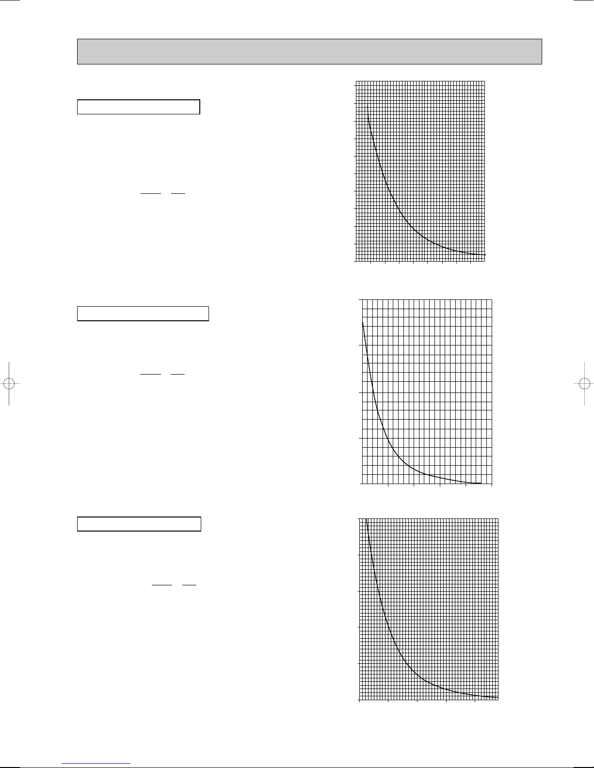
<Thermistor feature chart>
0
10
20
30
40
50
-20 -10 0 10 20 30 40 50
Temperature (:)
Resistance (k")
200
150
100
50
0
25 50 75 100110 125
Temperature (:)
Resistance (k")
500
400
300
200
100
0
25
50 75 100 120
Temperature (:)
Resistance (k")
Low temperature thermistors
Pipe temperature thermistor <Liquid> (TH3)
Pipe temperature thermistor <cond.> (TH6)
Outdoor temperature thermistor (TH7)
Gas pipe temperature thermistor (TH-A ~ TH-E)···· Branch box
Thermistor R0 = 15k' ±3%
B constant = 3480 ± 2%
1
t =15exp{3480(
R
0: 15k'
10: 9.6k'
1
273+t – 273
30: 4.3k'
40: 3.0k'
)}
20: 6.3k'
25: 5.4k'
Medium temperature thermistor
Heatsink temperature thermistor (TH8)
Thermistor R50 = 17k' ±2%
B constant = 4170 ± 3%
1
t =17exp{4170(
R
1
273+t – 323
)}
0: 180k'
25: 50k'
50: 17k'
70: 8k'
90: 4k'
High temperature thermistor
Discharge temperature thermistor (TH4)
Thermistor R120 = 7.465k' ±2%
B constant = 4057 ± 2%
t =7.465exp{4057(
R
20: 250k'
30: 160k'
40: 104k'
50: 70k'
60: 48k'
273+t – 393
70: 34k'
80: 24k'
90: 17.5k'
100: 13.0k'
110: 9.8k'
1
1
)}
55

BRANCH BOX : PAC-AK50BC
1
2
3
4
5
6
M
Blue
Brown
Yellow
Orange
Red
White
Parts name
Check points
Disconnect the connector then measure the resistance with a tester.
(At the ambient temperature 10:~30:)
Disconnect the connector then measure the resistance with a tester.
(
Winding temperature 20
:)
Thermistor (TH-A~E)
<Gas pipe>
Normal
4.3k"~9.6k"
Abnormal
Open or short
Normal
Red - White
Red - Orange
Brown - Yellow
Brown - Blue
Abnormal
46±4"
Linear expansion valve
( LEV-A~E )
Open or short
PAC-AK30BC
56

A
B
C
Open
Extra tightening (about 32 pulse)
Pulse number
500 pulse
Opening a valve
all the way
Close
Valve position (capacity)
LEV
M
1
6
[4
[4
[3
[2
[1
2
1
Red
Brown
Blue
Orange
Yellow
White
3
4
5
6
Connector LEV-A
LEV-B
LEV-C
LEV-D
LEV-E
DC12V
branch box controller board
Drive circuit
[3
[2
[1
3
2
5
4
Linear expansion valve
1
ON
OFF
OFF
OFF
ON
ON
OFF
OFF
OFF
ON
OFF
OFF
OFF
ON
ON
OFF
[1
Output
(Phase)
Output
[2
[3
[4
234
5678
OFF
OFF
ON
OFF
OFF
OFF
ON
ON
OFF
OFF
OFF
ON
ON
OFF
OFF
ON
(LEV) in Branch box
(1) Operation summary of the linear expansion valve
• Linear expansion valve open/close through stepping motor after receiving the pulse signal from the branch box controller
board.
• Valve position can be changed in proportion to the number of pulse signal.
<Connection between the branch box controller board and the linear expansion valve>
<Output pulse signal and the valve operation>
(2) Linear expansion valve operation
Opening a valve : 8 → 7 → 6 → 5 → 4 → 3 → 2 → 1 → 8
Closing a valve : 1 → 2 → 3 → 4 → 5 → 6 → 7 → 8 → 1
The output pulse shifts in above order.
• When linear expansion valve operation stops, all output phase
become OFF.
• When the switch is turned on, 700 pulse closing valve signal will be
sent till it goes to
A point in order to define the valve position.
(The pulse signal is being sent for about 20 seconds.)
• When the valve moves smoothly, there is no sound or vibration
occurring from the linear expansion valve : however, when the pulse
number moves from B to A or when the valve is locked, sound can
be heard.
No sound is heard when the pulse number moves from B to A in
case coil is burnt out or motor is locked by open-phase.
• Sound can be detected by placing the ear against the screw driver
handle while putting the screw driver to the linear expansion valve.
57

(3) How to attach and detach the coil of linear expansion valve
<Composition>
Linear expansion valve is separable into the main body and the coil as shown in the diagram below.
Coil
Lead wire
<How to detach the coil>
Hold the lower part of the main body (shown as A) firmly so that
the main body does not move and detach the coil by pulling it
upward.
Be sure to detach the coil holding main body firmly. Otherwise
pipes can bend due to pressure.
Stopper
Main body
<How to attach the coil>
Hold the lower part of the main body (shown as A) firmly so that
the main body does not move and attach the coil by inserting it
downward into the main body. Then securely attach the coil stopper to pipe B. (At this time, be careful that stress is not added to
lead wire and main body is not wounded by lead wire.) If the
stopper is not firmly attached to pipe B, coil may be detached
from the main body and that can cause defective operation of linear expansion valve.
To prevent piping stress, be sure to attach the coil holding the
main body of linear expansion valve firmly. Otherwise pipe may
break.
A
B
A
Be sure to attach the
stopper to pipe B.
58

Troubleshooting
Problem
Check point
Corrective measure
If the linear expansion valve becomes locked and the motor is still operating,
the motor will emit a clicking noise and will not function. This clicking noise
indicates an abnormality.
Use an all-purpose electrical meter to measure the resistance between the
different coils (red-white, red-orange, brown-yellow, brown-blue). Normal
resistance is within a range of 46"±4%.
In order to check the linear expansion valve, operate 1 indoor unit in the
fan mode and another in the cooling mode. Then, use the outdoor multi
controller board to operate the monitor and check the pipe temperature of
the indoor unit. The linear expansion valve should be fully closed when the
fan is operating. The temperature measured by the temperature sensor
will drop if there is any leakage.
If the measured temperature is significantly lower than that on the remote
controller, this indicates that the valve is not closed. It is not necessary to
replace the linear expansion valve if the leak of refrigerant is small and does
not cause a malfunction.
1 Check improperly connected connector terminals and the wire colors.
2 Remove the connector on the controller board side and check electrical
conductance.
Locked expansion
valve
Short circuit or broken
circuit in expansion
valve motor coil
Valve does not close
completely.
Incorrect connection
or connection failure
Replace the linear
expansion valve.
Replace the linear
expansion valve.
Replace the linear
expansion valve if there
is a major leak of
refrigerant.
Continuity check of
wrong part
59

9-7. TEST POINT DIAGRAM
9-7-1. Outdoor controller circuit board
MXZ-8A140VA MXZ-8A140VA1 MXZ-8A140VA2
CNS
Communication
power supply
ZD71 Voltage
developed across:
16-30V DC
CNAC
2 to 4: Power supply for
outdoor controller
circuit board
(220V-240V AC)
1 to 3: Power supply for
indoor and branch box /
outdoor unit connection
wire (220V-240V AC)
CN2
Connect to the outdoor
power circuit board (CN2)
1-5:
Power circuit board ➔
Transmitting signal to
the controller circuit board
(0-5V DC)
2-5: Zero cross signal
(0-5V DC)
3-4: Not used
6-5: 18V DC
7-5: 18V DC
[5: – 1,2,6,7: + ]
52C
Contactor
(Branch box/outdoor unit connecting wire)
+
–
<CAUTION> TEST POINT1 is high voltage.
VCC (TEST POINT 2)
(voltage between pins of C6B): DC 15V
63H
High pressure switch
VDC (TEST POINT 1)
(voltage between pins of
C5E): DC280V-350V
CNDC
DC280V-350V
+
Connect from
}
outdoor power
–
circuit board
(CNDC)
VSP (TEST POINT 3)
(voltage between pins of
C5A, C5B): DC 0V (when
stopped), DC 1– 6.5V
(when operated)
VFB (TEST POINT 4)
(voltage between right
pins of PC5C and
PC5D, pin 3 and pin 4)
TH6
Thermistor
<Outdoor 2-phase pipe>
TH7
Thermistor<Outdoor>
TH3
Thermistor
<Outdoor pipe>
TH4
Thermistor
<Discharge>
21S4
Four-way valve
SV2
Solenoid valve2
SV1
Solenoid valve1
CN4
Transmission
to outdoor
power circuit
board (CN4)
LED3
CN51
CNDM
1 to 2: Input of low noise mode
1 to 3: Input of external
contact point
CN3S
60
SW10
SW2
SW9
63HS
High pressure
sensor
63L
Low pressure switch
SW5
Function switch
SW6
Model setup
SW1
Forced defrost,
detect history
record reset
SW7
SW4
Test operation

Outdoor controller circuit board
MXZ-8A140VA3
SW1
Forced defrost,
detect history record reset
SW6
Model select
SW4
Test operation
SW5
Function switch
SW8
SW7
SW9
SW2
CN3S
<CAUTION> TEST POINT1 is high voltage.
CN51
CNDM
1 to 2:
Input of low noise
mode
1 to 3:
Input of external contact point
CN52C
(Connect to the noise
filter circuit board
(CN52C))
LED
CN4
Transmission to outdoor power circuit
board (CN4)
63L
Low pressure switch
63HS
High pressure sensor
TH4
Thermistor
<Discharge>
TH3
Thermistor
<Outdoor pipe>
TH7/6
Thermistor
<Outdoor/
2-phase pipe>
63H
High pressure
switch
VFG
(TEST POINT 4)
(Voltage between
right pins of PC5C
and PC5D, pin 3
and pin 4)
(Same as
(CNF1
7(+)-4(-))
VSP
(TEST POINT 3)
(Voltage between pins
of C5A, C5B): DC 0V
(when stopped), DC 1–
6.5V
(when operated)
CNF1, CNF2
Connect to the fan motor
1-4: 280V DC
5-4: 15V DC
6-4: 0-6.5V DC
7-4: 15V DC(When stopped)
7.5V DC(When operated)(0V-15V pulse)
CNDC
280V DC (1+, 3-)
Connect to outdoor power circuit
board(CNDC)
SV1
Solenoid valve 1
SV2
Solenoid valve 2
21S4
Four-way valve
CN2
Connect to the outdoor
power circuit board (CN2)
1-5: Reception from
2-5: Zero cross signal
3,4: Not used
6-5: 16V DC
7-5: 16V DC
CNAC
2 to 4: Power supply for
outdoor controller circuit
board (220V-240V AC)
1 to 3: Power supply for
indoor and outdoor unit
connection wire
(220-240V AC)
CNS
S1-S2: 220-240V AC
(Branch box/outdoor
unit connecting wire)
+ -
Communication power supply
D71 Voltage
24V DC
power circuit board
(0-5V DC)
61

9-7-2. Outdoor noise filter circuit board
MXZ-8A140VA
LO, NO
Voltage of 220-240V AC is output
(Connect to the outdoor power
circuit board (SC-R, SC-S))
CNAC1, CNAC2
220-240V AC
(Connect to the
outdoor controller
circuit board
(CNAC))
EI
Connect to
the earth
CN5
Primary current
(Connect to the
outdoor power
circuit board
(CN5))
LI, NI
Voltage of 220-240V AC is input
(Connect to the terminal block(TB1))
62

Outdoor noise filter circuit board
MXZ-8A140VA1
MXZ-8A140VA2
LO, NO
Voltage of 220-240V AC is output
(Connect to the outdoor power
circuit board)
TABS
TABT
CNAC1, CNAC2
220-240V AC
(Connect to the
outdoor controller
circuit board
(CNAC))
EI
Connect to
the earth
CN5
Primary current
(Connect to the
outdoor power
circuit board
(CN5))
LI, NI
Voltage of 220-240V AC is input
(Connect to the terminal block(TB1))
63

Outdoor noise filter circuit board
MXZ-8A140VA3
RS1
CNAC1, CNAC2
220-240V AC
(Connect to the
outdoor controller
circuit board
(CNAC))
CN52C
52C driving signal
(Connect to the outdoor
controller circuit board
(CN52C).)
LO, NO
Voltage of 220-240V AC
is output
(Connect to the outdoor
power circuit board
(TABS, TABT))
EI
Connect to
the earth
E2
Connect to the earth
CN5
Primary current
(Connect to the
outdoor power
circuit board
(CN5))
LI, NI
Voltage of 220-240V AC is input
(Connect to the terminal block(TB1)).
64

9-7-3. Outdoor power circuit board
MXZ-8A140VA
CN5
Detection of
primary current
(Connect to the
outdoor noise filter
circuit board (CN5))
CN3
Temperature
<Heatsink>
(TH8)
Brief Check of POWER MODULE
W Usually, they are in a state of being short-circuited if they are broken.
Measure the resistance in the following points (connectors, etc.).
If they are short-circuited, it means that they are broken.
1. Check of POWER MODULE
Note:The marks, L , N , N1 , N2 , P1 , P2 , U , V and W
shown in the diagram are not actually printed on the board.
CN4
Connect to the
outdoor controller
circuit board
(CN4)
1.Check of DIODE circuit
L - P1 , N - P1 , L - N1 , N - N1
2.Check of IGBT circuit
P2 - U , P2 - V , P2 - W , N2 - U , N2 - V , N2 - W
CN2
Connect to the outdoor controller circuit
CNAF
Connect to
ACTM
W
V
board (CN2)
1-5: Power circuit board
signal to the controller board (0-5V DC)
2-5: Zero cross signal (0-5V DC)
3-4: 18V DC
6-5: 15V DC
7-5: 15V DC
[ 5 : – 1, 2, 6, 7 : + ]
[ 4 : – 3 : + ]
➔ Transmitting
TAB-U, TAB-V,
TAB-W
Connect to the
compressor (MC)
Voltage among
phases:
5V-180V AC
SC-P1
Connect to 52C
N1
P2
P1
SC-N1
Connect to ACTM
POWER
MODULE
U
N2
SC-R, SC-S
Connect to the
outdoor noise filter
circuit board
(LO, NO)
N
L
CNDC
–
280V-350V DC
}
+
Connect to the outdoor controller
circuit board (CNDC)
220V-240V AC
SC-P2, SC-N2
Connect to
ACTM and the
soothing
capacitor
65

Outdoor power circuit board
MXZ-8A140VA1
MXZ-8A140VA2
MXZ-8A140VA3
Brief Check of POWER MODULE
W Usually, they are in a state of being short-circuited if they are broken.
Measure the resistance in the following points (connectors, etc.).
If they are short-circuited, it means that they are broken.
1. Check of POWER MODULE
1.Check of DIODE circuit
S - P1 , T - P1 , S - N1 , T - N1
2.Check of IGBT circuit
P2 - U , P2 - V , P2 - W , N2 - U , N2 - V , N2 - W
Note:The marks, L , N , N1 , N2 , P1 , P2 , U , V and W
shown in the diagram are not actually printed on the board.
CN2
Connect to the outdoor controller circuit board
(CN2)
1-5:Transmitting signal to the outdoor
controller circuit board (0~5V DC)
2-5:Zero cross signal (0~5V DC)
3-4:18V DC
6-5:16V DC
7-5:16V DC
CN3
Thermistor (TH8)
<Heatsink>
CN5
Detection of primary
current
Connect to the
outdoor noise filter
circuit board (CN5)
CN4
Connect to the
outdoor controller
circuit board
(CN4)
CNDC
310V DC (1+, 3–)
Connect to the outdoor
controller circuit board
TABS/T
Connect to the outdoor
noise filter circuit board
Voltage among
phases:220-240V AC
TABN1/SC-N1
Connect to the ACTM(-)
TABP1/SC-P1
Connect to 52C
TABP2/SC-P2
Connect to the
ACTM(P)
TABU/V/W
Connect to the compressor (MC)
Voltage among phases:10V~180V AC
66
TABN2/SC-N2
Connect to the
ACTM(N2)
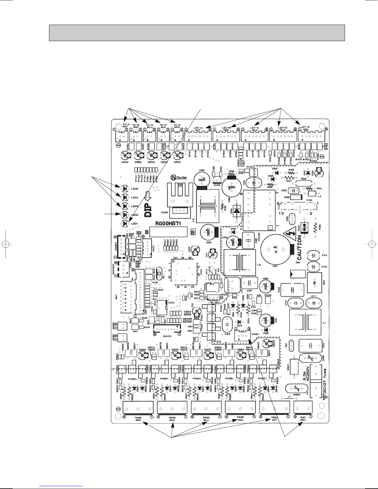
9-7-4. Branch box controller board
PAC-AK50BC
PAC-AK30BC
TH-A to E Connect to
Thermistor-A to E
TH-A to C for PAC-AK30BC
LED3~5
Not used
LED2
Transmission
(Branch box/outdoor)
Reception state disply
on branch box side
Branch box No.1
LED2 blinks once.
(0.1sec. : ON,
0.9sec. : OFF)
LED1
Transmission start-up state display
Start-up : LED1 blinks
(0.5sec. : ON, 0.5sec. : OFF)
Start-up completion:LED1 lights
LEV-Ato E
Connect to LEV-Ato E
LEV-Ato C for PAC-AK30BC
Branch box No.2
LED2 blinks twice.
(0.1sec. : ON,
0.1sec. : OFF
0.1sec. : ON,
0.7sec. : OFF)
*The blinking interval
might change when
there are changes in
states of indoor units.
TB3A toTB3E
Connect to TB3A to TB3E
(Branch box / Indoor unit connecting wire)
TB3A to TB3C for PAC-AK30BC
CN3C, CND
Connect to TB2B
(Branch box / Outdoor unit
connecting wire)
67

9-7-5. Active filter module
DCL
L1 L2
ACTM
P
I
N1
N2
(+)
(-)
Load
MXZ-8A140VA
MXZ-8A140VA1
MXZ-8A140VA2
–
Connect to the
outdoor power
circuit
board(TABN1)
+
Connect to the outdoor
power circuit board(TABP1)
L1, L2
Connect to the DCL(Reactor)
Connect to the outdoor
power circuit
board(CNAF)
1 : GND
2-1 : 15V DC
3-1 : Control signal
4, 5 : Not used
6-1 : Control signal
I
Not used
N2
Connect to the
outdoor power
circuit
board(TABN2)
Connection and internal circuit diagram
P
Connect to the outdoor power circuit
board(TABP2)
N1
Non-connect
68

Active filter module
DCL
L1 L2
ACTM
P
I
N1
N2
(+)
(- )
Load
MXZ-8A140VA3
L1, L2
Connect to the
DCL(Reactor)
P
Connect to the outdoor power
circuit board(TABP2)
N1
Non-connect
Upper side
+
Connect to the
outdoor power
circuit board
(TABP1)
–
Connect to the outdoor power
circuit board(TABN1)
Connect to the outdoor power
circuit board(CNAF)
1 : GND
2-1 : 15V DC
3-1 : Control signal
4, 5 : Not used
6-1 : Control signal
Lower side
N2
Non-connect
Io
Connect to the outdoor power
circuit board(TABN2)
Connection and internal circuit diagram
69
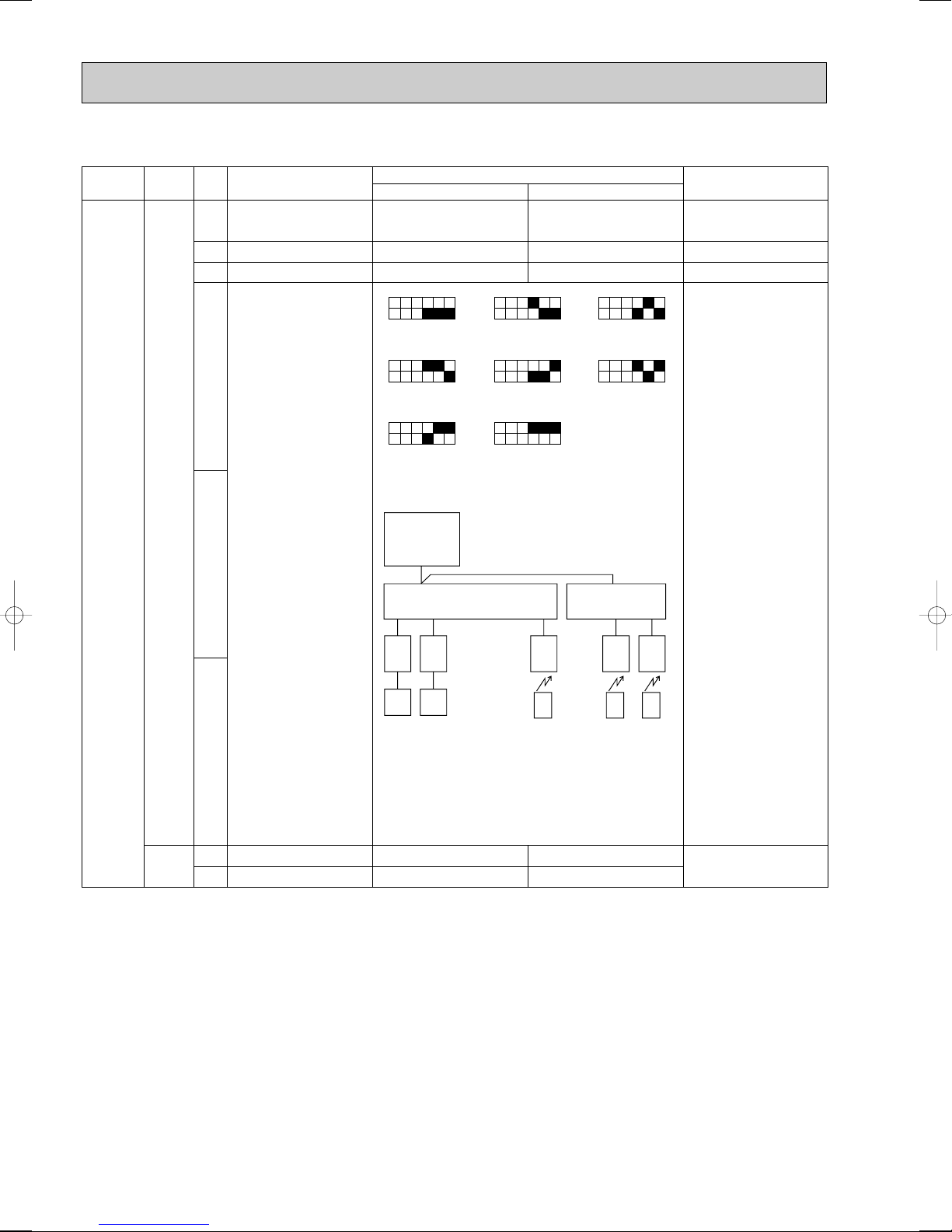
Forced defrost Start
Normal
Normal
—
When compressor is
working in heating
operation. w
Abnormal history clear
No function
Self-diagnosis
(Indoor unit selection)
Indicating a particular
self-diagnosis
Clear
—
off or operating
—
Test run Operating OFF
Under suspension
Test run mode setting
Heating Cooling
Indoor No.1
Indoor No.4
Indoor No.7
Indoor No.2
Indoor No.5
Indoor No.8
Indoor No.3
Indoor No.6
1
2
3
4
5
6
1
2
ON OFF
No.
Function Effective timing
Action by the switch operation
Switch
SW1
Dip
switch
SW4
Type of
Switch
OC
<Example>
ABCDEABC
ICRCIC IC
RC
Indoor
No.1
Indoor
No.2
Indoor
No.3
Indoor
No.4
Indoor
No.5
R
C
IC
R
C
IC
R
C
BC#1 (5- branch type)
BC#2
(3- branch type)
BC#1 : branch box controller unit Number 1
1 blinking LED2 (branch box controller board)
BC#2 : branch box controller unit Number 2
2 blinking LED2 (branch box controller board)
1ON23456
1ON23456
1ON23456
1ON23456
1ON23456
1ON23456
1ON23456
1ON23456
9-8. FUNCTION OF SWITCHES, CONNECTORS AND JUMPERS
(1) Function of switches
Forced defrost should be done as follows.
1Change the DIP SW1-1 on the outdoor controller board from OFF to ON.
2Forced defrost will start by the above operation 1 if these conditions written below are satisfied.
• Heat mode setting
• 10 minutes have passed since compressor started operating or previous forced defrost finished.
• Pipe temperature is less than or equal to 8:.
3Forced defrost will finish if certain conditions are satisfied.
wForced defrost can be done if above conditions are satisfied when DIP SW1-1 is changed from OFF to ON.
After DIP SW1-1 is changed from OFF to ON, there is no problem if DIP SW1-1 is left ON or changed to OFF again. This
depends on the service conditions.
70

MXZ-8A140VA MXZ-8A140VA1 MXZ-8A140VA2
Type of
Switch
Dip
switch
Switch
SW5
SW7
SW8
SW6
SW9
No.
1
2
3
4
1
2
3
4
5
6
1
2
3
1
2
3
4
5
6
1
2
Function Effective timing
No function
Switching the target
sub-cool
No function
No function
Demand switching
function
No function
Max. Frequency down
No function
No function
No function
No function
No function
No function
Model selection
LEV opening setting
function for stopping
unit during heating
operation
Switching function of
defrosting prohibited
time
(Heating mode)
Action by the switch operation
ON OFF
—
Target sub-cool down
—
—
Capability cut
50%
—
Active
—
—
—
—
—
—
Changed
60 minutes
—
Normal
—
—
Normal
—
Normal
—
—
—
—
—
—
SW6
1ON23456
Normal
30 minutes
(Normal)
—
Always
—
—
Always
—
Always
—
—
—
—
—
—
Always
Always
SW10
Switching the Input
1
Current Limit Level
During the FAN or COOL
mode, and thermo - OFF in
heating operation, set the
2
opening of liner expansion
valve on branch box
3 A down
Active
Normal
Inactive
Before turning
the power on
While unit stopping
71

CN31
Types Connector Function Effective timing
Connector
Open a little bit
Pin 1-2 Short Pin 2-3 Short
Action by Pin short operation
LEV opening function
(at start-up)
When power supply ON
Normal
MXZ-8A140VA3
Type of
Switch
switch
Switch
SW5
SW7
SW8
Dip
SW6
SW9
No.
1
2
3, 4
5, 6
1
2
3
4
5
6
1
2
3
1
2
3
4
5
6
7
8
1
2
3
4
Function Effective timing
No function
Switching the target
sub-cool
Demand switching
function
Max. Frequency down
LEV opening setting
function for stopping
unit during heating
operation
Switching function of
defrosting prohibited
time
Switching the Input
Current Limit Level
During the FAN or COOL
mode, and thermo - OFF in
heating operation, set the
opening of liner expansion
valve on branch box
(Heating mode)
No function
No function
No function
No function
No function
No function
No function
No function
No function
Model selection
Action by the switch operation
ON OFF
—
Target sub-cool down
—
—
Capability cut
50%
—
Active
—
—
—
—
—
—
Changed
60 minutes
3 A down
Active
—
Normal
—
—
Normal
—
Normal
—
—
—
—
—
—
SW6
1ON2345678
Normal
30 minutes
(Normal)
Normal
Inactive
—
Always
—
—
Always
—
Always
—
—
—
—
—
—
Always
Always
Before turning
the power on
While unit stopping
(2) Function of connector
72

<Outdoor unit operation monitor function>
1ON23456
1ON23456
1 second
interval
Display Operation Model
The tens digit : Operation mode
The ones digit : Relay output
O
C
H
d
Display
0
1
2
3
4
5
6
7
8
A
Compressor
Warming-up
Compressor
4-way valve
Solenoid valve
(SV1, 2)
—
—
—
—
ON
ON
ON
ON
—
—
—
—
—
—
—
—
—
—
ON
ON
—
—
ON
ON
—
—
ON
ON
—
ON
—
ON
—
ON
—
ON
—
ON
—
—
OFF / FAN
COOLING / DRY
HEATING
DEFROSTING
Display Contents to be inspected (When power is turned on)
F3
F5
F9
E8
E9
EA
Eb
Ec
E0~E7
63L connector(red) is open.
63H connector(yellow) is open.
2 connectors (63H/63L) are open.
Branch box/outdoor communication error (Signal receiving error) (Outdoor unit)
Indoor/branch box communication error (Signal receiving error) (Branch box)
Branch box/outdoor communication error (Transmitting error) (Outdoor unit)
Indoor/branch box communication error (Transmitting error) (Branch box)
• Miswiring of indoor - branch box/branch box - outdoor unit connecting wire
• Too many indoor units/branch box are in the system.
Miswiring of indoor - branch box/branch box - outdoor unit connecting wire(converse wiring or disconnection)
Startup time over
Communication error except for outdoor unit
Display Inspection unit
01Outdoor unit,
Branch box unit
Indoor unit
Display Contents to be inspected (During operation)
U2
U7
U1
UL
U6
UF
UH
UP
U3
U4
U5
U8
U9
PA
Discharge temperature fault
Low-discharge superheating fault, Erroneous connection of refrigerant pipes or the
connecting wires
High pressure fault (63H operates)
Low pressure fault (63L operates)
Abnormality of power modules
Compressor overcurrent shutoff (Start up locked)
Current sensor fault (P. B.)
Compressor overcurrent shutoff fault
Discharge pipe/compressor thermistor (TH4) open or short-circuit
Outdoor unit thermistors (TH3, TH6, TH7, and H8), 63HS, and branch box thermistors
open or short-circuit
HEATSINK temperature fault
Abnormality in outdoor fan motor
Voltage fault, current sensor fault (N. F.)
Forced compressor stop
(Overlap malfunction of drain pump in indoor unit and linear expansion valve in branch box.)
Digital indicator LED3 displays 2 digit number or code to inform operation condition and the meaning of error code by
controlling DIP SW2 on outdoor controller.
Operation indicator SW2 : Indicator change of self diagnosis
SW2 setting
Display detail
Explanation for display Unit
<Digital indicator LED3 working details>
(Be sure that 1 to 6 in the SW2 are set to OFF.)
(1) Display when the power supply is ON.
When the power supply is ON, blinking displays by turns.
Wait for 4 minutes at the longest.
(2) When the display lights (Normal operation)
1Operation mode display
(Lighting)
LED3
2Display during error postponement
Postponement code is displayed when
compressor stops due to the work of
protection device.
Postponement code is displayed while
error is being postponed.
(3) When the display blinks
Inspection code is displayed when compressor stops due to the work of protection devices.
SW2
(Initial setting)
73

SW2 setting
1ON23456
1ON23456
1ON23456
1ON23456
1ON23456
1ON23456
1ON23456
1ON23456
1ON23456
10
1ON23456
1
05
4
25
2
45
1
25
1
50
1ON23456
Indoor unit 1
Indoor unit 2
Indoor unit 3
Indoor unit 4
Indoor unit 5
Indoor unit 6
Indoor unit 7
Indoor unit 8
0
1
0
1
0
1
0
1
0
0
1
1
0
0
1
1
0
0
0
0
1
1
1
1
SW1
65
4
Display detail
Pipe temperature / Liquid(TH3)
– 40~90
Explanation for display Unit
– 40~90
(When the coil thermistor detects 0: or below, “–”
and temperature are displayed by turns.)
(Example)
When –10:; 0.5 secs. 0.5secs. 2 secs.
:
Discharge temperature (TH4)
3~217
Output step of outdoor FAN
0~10
The number of ON / OFF times of
compressor
0~9999
Compressor integrating operation times
0~9999
Compressor operating current
0~50
3~217
(When the discharge thermistor detects 100: or
more, hundreds digit, tens digit and ones digit are
displayed by turns.)
(Example)
When 105:; 0.5 secs. 0.5secs. 2 secs.
0~10
0~9999
(When the number of times is 100 or more,
hundreds digit, tens digit and ones digit are
displayed by turns.)
(Example) When 42500 times (425
✕100 times);
0.5 secs. 0.5secs. 2 secs.
0~9999
(When it is 100 hours or more, hundreds digit, tens
digit and ones digit are displayed by turns.)
(Example) When 2450 hours (245 ✕10 hours);
0.5 secs. 0.5secs. 2 secs.
0~50
wOmit the figures after the decimal fractions.
:
Step
100 times
10 hours
A
Compressor operating frequency
0~225
LEV opening pulse
0~500
Error postponement code history (1)
of outdoor unit
Operation mode on error occurring Operation mode of when operation stops due to
0~255
(When it is 100Hz or more, hundreds digit, tens
digit and ones digit are displayed by turns.
(Example)
When 125Hz; 0.5 secs. 0.5secs. 2 secs.
0~500
(When it is 100 pulse or more, hundreds digit, tens
digit and ones digit are displayed by turns.
(Example)
When 150 pulse; 0.5 secs. 0.5secs. 2 secs.
Postponement code display
Blinking: During postponement
Lighting: Cancellation of postponement
“00” is displayed in case of no postponement.
error is displayed by setting SW2 like below.
(SW2)
74
Hz
Pulse
Code
display
Code
display

SW2 setting
1ON23456
1ON23456
1ON23456
1ON23456
1ON23456
1ON23456
15
1302
45
1
05
1ON23456
Indoor unit 1
Indoor unit 2
Indoor unit 3
Indoor unit 4
Indoor unit 5
Indoor unit 6
Indoor unit 7
Indoor unit 8
0
1
0
1
0
1
0
1
0
0
1
1
0
0
1
1
0
0
0
0
1
1
1
1
SW1
65
4
Display detail
Pipe temperature / Liquid(TH3) on error
occurring
– 40~90
Explanation for display Unit
– 40~90
(When the coil thermistor detects 0: or below, “–”
and temperature are displayed by turns.)
(Example)
When –15:; 0.5 secs. 0.5secs. 2 secs.
:
Compressor temperature (TH4) or
discharge temperature (TH4) on error
occurring
3~217
Compressor operating current on error
occurring
0~50
Error code history (1) (latest)
Alternate display of abnormal unit
number and code
Error code history (2)
Alternate display of error unit number
and code
Thermostat ON time
0~999
3~217
(When the temperature is 100: or more, the
hundreds digit, tens digit and ones digit are
displayed by turns.)
(Example)
When –15:; 0.5 secs. 0.5secs. 2 secs.
0~50
When no error history,
“ 0 ” and “–” are displayed by turns.
When no error history,
“ 0 ” and “–” are displayed by turns.
0~999
(When it is 100 minutes or more, the hundreds digit,
tens digit and ones digit are displayed by turns.)
(Example)
When 245 minutes; 0.5 secs. 0.5secs. 2 secs.
:
A
Code
display
Code
display
Minute
Test run elapsed time
0~120
Capacity code of indoor unit (Qj)
0~120
(When it is 100 minutes or more, the hundreds digit,
tens digit and ones digit are displayed by turns.)
(Example)
When 105 minutes; 0.5 secs. 0.5secs. 2 secs.
The capacity code of indoor unit is displayed.
75
Minute
Code
display

SW2 setting
1ON23456
1ON23456
1ON23456
1ON23456
1ON23456
Capacity
MXZ-8A140VA
Code
25
Setting details
• The tens digit (Total display for applied setting)
• The ones digit
H·P /
Cooling only
Single phase / 3 phase
Display details
0 : H·P 1 : Cooling only
0 :
Single phase
2 : 3 phase
Setting details
Defrosting switch
Display details
0 : Normal 1 : For high humidity
1ON23456
1ON23456
Indoor unit 1
Indoor unit 2
Indoor unit 3
Indoor unit 4
Indoor unit 5
Indoor unit 6
Indoor unit 7
Indoor unit 8
0
1
0
1
0
1
0
1
0
0
1
1
0
0
1
1
0
0
0
0
1
1
1
1
SW1
65
4
Indoor unit 1
Indoor unit 2
Indoor unit 3
Indoor unit 4
Indoor unit 5
Indoor unit 6
Indoor unit 7
Indoor unit 8
0
1
0
1
0
1
0
1
0
0
1
1
0
0
1
1
0
0
0
0
1
1
1
1
SW1
65
4
Indoor unit 1
Indoor unit 2
Indoor unit 3
Indoor unit 4
Indoor unit 5
Indoor unit 6
Indoor unit 7
Indoor unit 8
0
1
0
1
0
1
0
1
0
0
1
1
0
0
1
1
0
0
0
0
1
1
1
1
SW1
65
4
Indoor unit 1
Indoor unit 2
Indoor unit 3
Indoor unit 4
Indoor unit 5
Indoor unit 6
Indoor unit 7
Indoor unit 8
0
1
0
1
0
1
0
1
0
0
1
1
0
0
1
1
0
0
0
0
1
1
1
1
SW1
65
4
Display detail
Explanation for display
Capacity setting display Displayed as an outdoor capacity code.
Outdoor unit setting information
(Example) MXZ-8A140VA, “00” is displayed.
Unit
Code
display
Code
display
Indoor pipe temperature / Liquid
– 39~88
Indoor pipe temperature / Cond. / Eva.
Indoor
– 39~88
Branch box pipe temperature / gas
– 39~88
– 39~88
(When the temperature is 0: or less, “–” and
temperature are displayed by turns.)
:
– 39~88
(When the temperature is 0: or less, “–” and
temperature are displayed by turns.)
:
– 39~88
(When the temperature is 0: or less, “–” and
temperature are displayed by turns.)
:
Targeted evaporating temperature : ETm
(Cooling)
Targeted high pressure : Pdm (Heating)
– 39~88
Indoor room temperature
8~39
– 39~88
(When the temperature is 0: or less, “–” and
temperature are displayed by turns.)
8~39
76
:
of/f
:

1ON23456
1ON23456
1ON23456
1ON23456
1ON23456
SW2 setting
1ON23456
1ON23456
1ON23456
1ON23456
Indoor unit 1
Indoor unit 2
Indoor unit 3
Indoor unit 4
Indoor unit 5
Indoor unit 6
Indoor unit 7
Indoor unit 8
0
1
0
1
0
1
0
1
0
0
1
1
0
0
1
1
0
0
0
0
1
1
1
1
SW1
65
4
Display detail
Indoor setting temperature
17~30
Explanation for display Unit
17~30
:
1ON23456
Outdoor pipe temperature / Cond./
Eva. (TH6)
– 39~88
Outdoor temperature (TH7)
– 39~88
Outdoor heatsink temperature (TH8)
– 40~200
Discharge superheat. SHd
0~255
Sub-cool. SC (cooling mode)
0~130
– 39~88
(When the temperature is 0: or less, “–” and
temperature are displayed by turns.)
– 39~88
(When the temperature is 0: or less, “–” and
temperature are displayed by turns.)
– 40~200
(When the temperature is 0: or less, “–” and
temperature are displayed by turns.)
(When the thermistor detects 100: or more,
hundreds digit, tens digit and ones digit are
displayed by turns.)
0~255
(When the temperature is 100°C or more, hundreds
digit, tens digit and ones digit are displayed by
turns.)
0~130
(When the temperature is 100°C or more, hundreds
digit, tens digit and ones digit are displayed by turns.)
:
:
:
°C
°C
Input current of outdoor unit 0~500
High pressure 63HS 0~500
Targeted operation frequency
0~255
DC bus voltage
180~370
(When it is 100 or more, hundreds digit, tens digit
and ones digit are displayed by turns.)
(When it is 100 or more, hundreds digit, tens
digit and ones digit are displayed by turns.)
(0~4.9MPa)
0~255
(When it is 100Hz or more, hundreds digit, tens
digit and ones digit are displayed by turns.)
180~370
(When it is 100V or more, hundreds digit, tens
digit and ones digit are displayed by turns.)
77
0.1 A
0.1 of/f
Hz
V

SW2 setting
1ON23456
1ON23456
1ON23456
1ON23456
1ON23456
1ON23456
25
1
1ON23456
30
1
Indoor unit 1
Indoor unit 2
Indoor unit 3
Indoor unit 4
Indoor unit 5
Indoor unit 6
Indoor unit 7
Indoor unit 8
0
1
0
1
0
1
0
1
0
0
1
1
0
0
1
1
0
0
0
0
1
1
1
1
SW1
65
4
1ON23456
Indoor unit 1
Indoor unit 2
Indoor unit 3
Indoor unit 4
Indoor unit 5
Indoor unit 6
Indoor unit 7
Indoor unit 8
0
1
0
1
0
1
0
1
0
0
1
1
0
0
1
1
0
0
0
0
1
1
1
1
SW1
65
4
1ON23456
Display detail
Target Sub-cool (Cooling mode) : SCm 0~255
Explanation for display Unit
:
Error postponement code history (2)
of outdoor unit
Error postponement code history (3)
of outdoor unit
Error code history (3) (Oldest)
Alternate display of abnormal unit number and code
Error thermistor display
When there is no error thermistor,
“–“ is displayed.
Operation frequency on error occurring
0~255
Postponement code display
Blinking: During postponement
Lighting: Cancellation of postponement
“00” is displayed in case of no postponement.
Postponement code display
Blinking: During postponement
Lighting: Cancellation of postponement
“00” is displayed in case of no postponement.
When no error history, “0” and “–“ are displayed by
turns.
3
: Outdoor pipe temperature /Liquid (TH3)
7
: Outdoor outside temperature (TH7)
8
: Outdoor radiator panel (TH8)
23
: Branch box pipe temperature / Gas (TH–A~E)
63
: High pressure sensor (63HS)
0~255
(When it is 100Hz or more, hundreds digit, tens digit
and ones digit are displayed by turns.)
(Example)
When 125Hz; 0.5 secs. 0.5secs. 2 secs.
Code
display
Code
display
Code
display
Code
display
Hz
Fan step on error occurring
0~10
LEV opening pulse on error occurring
0~500
Indoor room temperature
on error occurring
8~39
0~10
0~500
(When it is 100 pulse or more, hundreds digit, tens
digit and ones digit are displayed by turns.)
(Example)
When 130 pulse; 0.5 secs. 0.5secs. 2 secs.
8~39
78
Step
Pulse
:

SW2 setting
1ON23456
1ON23456
1ON23456
1ON23456
1ON23456
15
15
15
15
Indoor unit 1
Indoor unit 2
Indoor unit 3
Indoor unit 4
Indoor unit 5
Indoor unit 6
Indoor unit 7
Indoor unit 8
0
1
0
1
0
1
0
1
0
0
1
1
0
0
1
1
0
0
0
0
1
1
1
1
SW1
65
4
Indoor unit 1
Indoor unit 2
Indoor unit 3
Indoor unit 4
Indoor unit 5
Indoor unit 6
Indoor unit 7
Indoor unit 8
0
1
0
1
0
1
0
1
0
0
1
1
0
0
1
1
0
0
0
0
1
1
1
1
SW1
65
4
50
1
1ON23456
1ON23456
15
1
Display detail
Indoor pipe temperature / Liquid on
error occurring
– 39~88
Explanation for display Unit
– 39~88
(When the temperature is 0°C or less, “–” and
temperature are displayed by turns.)
(Example)
When –15°C; 0.5 secs. 0.5secs. 2 secs.
:
Indoor pipe temperature / Cond./ Eva.
on error occurring
– 39~88
Outdoor pipe temperature / Cond./ Eva.
(TH6) on error occurring
– 39~88
Outdoor outside temperature (TH7) on
error occurring
– 39~88
Outdoor heatsink temperature (TH8) on
error occurring
– 40~200
– 39~88
(When the temperature is 0°C or less, “–” and
temperature are displayed by turns.)
(Example)
When –15°C; 0.5 secs. 0.5secs. 2 secs.
– 39~88
(When the temperature is 0°C or less, “–” and
temperature are displayed by turns.)
(Example)
When –15°C; 0.5 secs. 0.5secs. 2 secs.
– 39~88
(When the temperature is 0°C or less, “–” and
temperature are displayed by turns.)
(Example)
When –15°C; 0.5 secs. 0.5secs. 2 secs.
– 40~200
(When the temperature is 0°C or less, “–” and
temperature are displayed by turns.)
(When the temperature is 100°C or more, hundreds
digit, tens digit and ones digit are displayed by
turns.)
:
:
:
:
Discharge superheat on error occurring
SHd
0~255
Sub-cool on error occurring. SC
0~130
0~255
(When the temperature is 100°C or more, hundreds
digit, tens digit and ones digit are displayed by
turns.)
(Example)
When 150°C; 0.5 secs. 0.5secs. 2 secs.
0~130
(When the temperature is 100°C or more, hundreds
digit, tens digit and ones digit are displayed by
turns.)
(Example)
When 115°C; 0.5 secs. 0.5secs. 2 secs.
79
:
:

SW2 setting
1ON23456
15
4
1ON23456
Normal
Overvoltage error
Undervoltage error
T phase interruption error
Abnormal power synchronous signal
PFC error
(Overvoltage / Undervoltage / Overcurrent)
W Display examples for multiple errors:
Overvoltage (01) + Undervoltage (02) = 03
Undervoltage (02) + Power-sync signal error (08) = 0A
T phase interruption (04) + PFC error (10) = 14
Power circuit board
Controller circuit board
Controller circuit board
Power circuit board
Power circuit board
—
Description Detection point Display
00
01
02
04
08
10
1ON23456
∆tj
Cooling Heating
∆tj = room temp. – Set temp. ∆tj = Set temp. – room temp.
Code of the difference between room temperature and
set temperature ("∆tj")
0
1
2
3
4
5
6
7
8
9
000
100
010
110
001
101
011
111
Indoor unit 1
Indoor unit 2
Indoor unit 3
Indoor unit 4
Indoor unit 5
Indoor unit 6
Indoor unit 7
Indoor unit 8
∆tj [ –0.5
–1.0 < ∆tj [ –0.5
–0.5 < ∆tj [ –0.5
0.0 < ∆tj [ 0.0
0.5 < ∆tj [ 0.5
1.0 < ∆tj [ 1.0
1.5 < ∆tj [ 0.5
2.0 < ∆tj [ 2.0
2.5 < ∆tj [ 2.5
3.0 < ∆tj [ 3.0
∆tj [ –0.5
–0.5 < ∆tj [ 0.0
0.0 < ∆tj [ 0.5
0.5 < ∆tj [ 1.0
1.0 < ∆tj [ 1.5
1.5 < ∆tj [ 2.0
2.0 < ∆tj [ 2.5
2.5 < ∆tj [ 3.0
3.0 < ∆tj [ 3.5
3.5 < ∆tj
SW setting (1-4, 5, 6)
Target unit
1ON23456
1ON23456
Indoor unit 1
Indoor unit 2
Indoor unit 3
Indoor unit 4
Indoor unit 5
Indoor unit 6
Indoor unit 7
Indoor unit 8
0
1
0
1
0
1
0
1
0
0
1
1
0
0
1
1
0
0
0
0
1
1
1
1
SW1
65
4
Display detail
Thermostat-on time until error stops
0~999
Target rotation of outdoor fan motor 0~999
Sub-cool (Heating mode) 0~130
Code of the difference between room
temperature and set temperature
("∆Tj": 0–99)
■Tens digit of code: current ∆Tj
■Units digit of code: ∆Tj a minute
ago
0~999
(When it is 100 minutes or more, hundreds digit, tens
digit and ones digit are displayed by turns.)
(Example) When 415 minutes;
Explanation for display Unit
0.5 secs. 0.5secs. 2 secs.
Minute
rpm
:
U9 Error status during the Error
postponement period
Code
display
Code
display
80

<Branch box unit operation monitor function>
1ON23456
1ON23456
1 second
interval
1ON23456
10
1ON23456
1
05
1ON23456
1ON23456
1
25
1ON23456
1ON23456
1
50
[When option part ‘A-Control Service Tool(PAC-SK52ST)’ is connected to branch box controller board(CNM)]
Digital indicator LED1 displays 2 digit number or code to inform operation condition and the meaning of error code by
controlling DIP SW2 on ‘A-Control Service Tool’.
Operation indicator SW2 : Indicator change of self diagnosis
SW2 setting
Display detail
Explanation for display Unit
<Digital indicator LED1 working details>
(Be sure that 1 to 6 in the SW2 are set to OFF.)
(1) Display when the power supply is ON.
When the power supply is ON, blinking displays by turns.
Wait for 2 minutes at the longest.
(2) When the display lights (Normal operation)
1The number of connected indoor units to this branch box (0 - 5)
LED1
(Lighting)
Pipe temperature / Liquid(TH3)
– 40~90
Discharge temperature (TH4)
3~217
Output step of outdoor FAN
0~15
Unit number of this branch box
1~2
SW2
(Initial setting)
– 40~90
(When the coil thermistor detects 0: or below, “–”
and temperature are displayed by turns.)
(Example)
When –10:; 0.5 secs. 0.5secs. 2 secs.
3~217
(When the discharge thermistor detects 100: or
more, hundreds digit, tens digit and ones digit are
displayed by turns.)
(Example)
When 105:; 0.5 secs. 0.5secs. 2 secs.
0~15
1 or 2
wOmit the figures after the decimal fractions.
:
:
Step
code
display
Compressor operating frequency
0~225
LEV-Aopening pulse
0~500
0~255
(When it is 100Hz or more, hundreds digit, tens
digit and ones digit are displayed by turns.
(Example)
When 125Hz; 0.5 secs. 0.5secs. 2 secs.
0~500
(When it is 100 pulse or more, hundreds digit, tens
digit and ones digit are displayed by turns.
(Example)
When 150 pulse; 0.5 secs. 0.5secs. 2 secs.
81
.Hz
Pulse

SW2 setting
1ON23456
1ON23456
1
50
1
50
1ON23456
1ON23456
1ON23456
1ON23456
1ON23456
1ON23456
1
50
1
50
1ON23456
1ON23456
Code display
(Not Qj)
2
3
4
5
6
7
8
9
10
11
12
13
Rated
capacity
22
25
28
32
35
40
45
50
56
60
71
80
Display detail
LEV-B opening pulse
0~500
Explanation for display Unit
0~500
(When it is 100 pulse or more, hundreds digit, tens
digit and ones digit are displayed by turns.
(Example)
When 150 pulse; 0.5 secs. 0.5secs. 2 secs.
Pulse
LEV-C opening pulse
0~500
LEV-D opening pulse
0~500
LEV-E opening pulse
0~500
Capacity setting indoor-A
0~14
0~500
(When it is 100 pulse or more, hundreds digit, tens
digit and ones digit are displayed by turns.
(Example)
When 150 pulse; 0.5 secs. 0.5secs. 2 secs.
0~500
(When it is 100 pulse or more, hundreds digit, tens
digit and ones digit are displayed by turns.
(Example)
When 150 pulse; 0.5 secs. 0.5secs. 2 secs.
0~500
(When it is 100 pulse or more, hundreds digit, tens
digit and ones digit are displayed by turns.
(Example)
When 150 pulse; 0.5 secs. 0.5secs. 2 secs.
Pulse
Pulse
Pulse
Code
display
Capacity setting indoor-B
0~14
Capacity setting indoor-C
0~14
Capacity setting indoor-D
0~14
Capacity setting indoor-E
0~14
Indoor pipe temperature / Liquid
TH2
Indoor-A
– 39~88
– 39~88
(When the temperature is 0: or less, “–” and
temperature are displayed by turns.)
82
Code
display
Code
display
Code
display
Code
display
:

SW2 setting
1ON23456
1ON23456
1ON23456
1ON23456
1ON23456
1ON23456
1ON23456
1ON23456
1ON23456
1ON23456
1ON23456
Display detail
Indoor pipe temperature / Liquid
TH2
Indoor-B
– 35~88
Explanation for display
– 35~88
(When the temperature is 0: or less, “–” and
temperature are displayed by turns.)
Unit
:
Indoor pipe temperature / Liquid
TH2
Indoor-C
– 39~88
Indoor pipe temperature / Liquid
TH2
Indoor-D
– 39~88
Indoor pipe temperature / Liquid
TH2
Indoor-E
– 39~88
LEV-1 opening pulse
0~500
LEV-2 opening pulse
0~500
– 39~88
(When the temperature is 0: or less, “–” and
temperature are displayed by turns.)
– 39~88
(When the temperature is 0: or less, “–” and
temperature are displayed by turns.)
– 39~88
(When the temperature is 0: or less, “–” and
temperature are displayed by turns.)
0~500
0~500
:
:
:
Pulse
Pulse
LEV-3 opening pulse
0~500
LEV-4 opening pulse
0~500
LEV-5 opening pulse
0~500
Outdoor pipe temperature / Cond./Eva.
(TH6)
– 39~88
Outdoor outside temperature (TH7)
– 39~88
0~500
0~500
0~500
– 39~88
(When the temperature is 0: or less, “–” and
temperature are displayed by turns.)
– 39~88
(When the temperature is 0: or less, “–” and
temperature are displayed by turns.)
Pulse
Pulse
Pulse
:
:
83
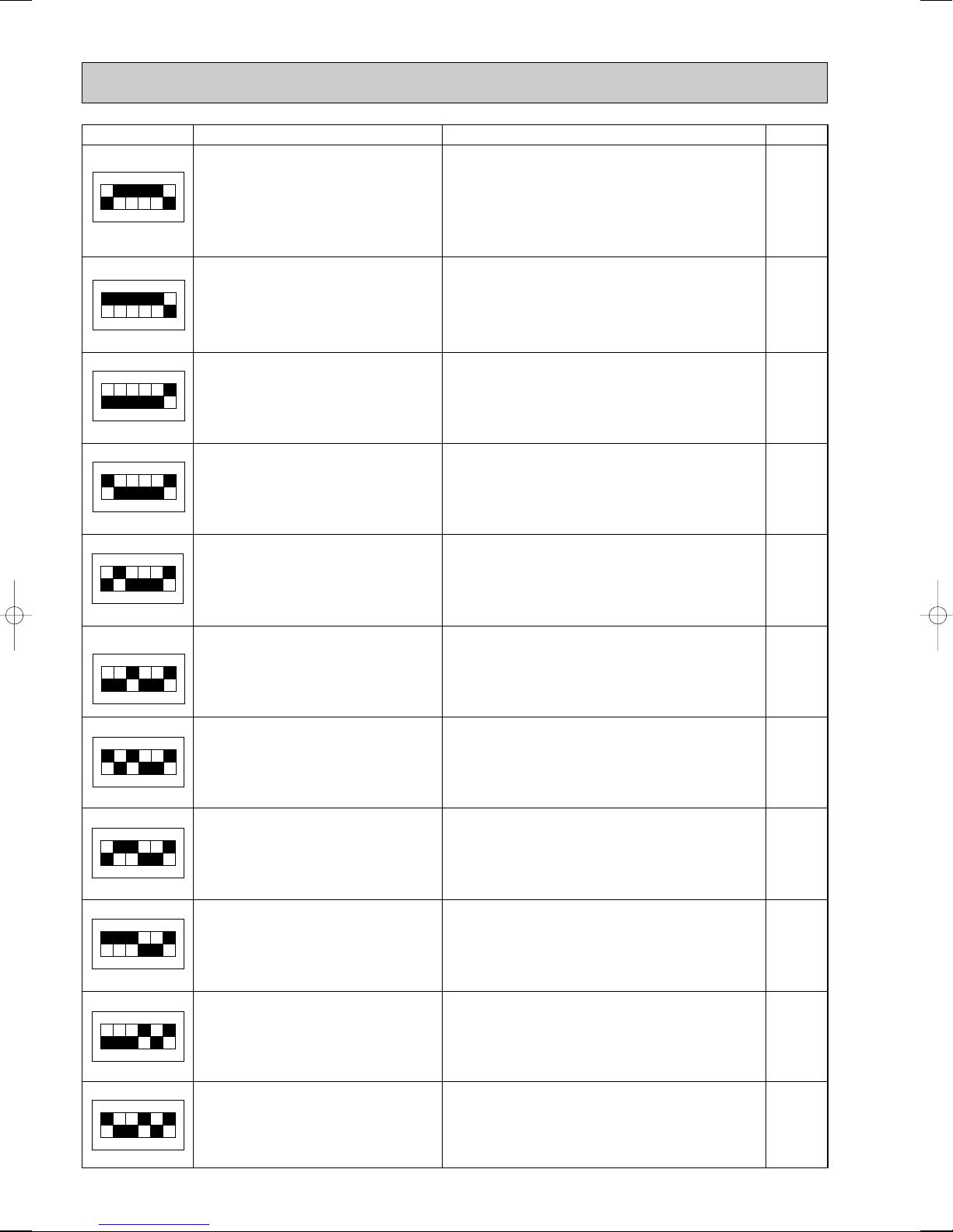
1ON23456
1ON23456
1ON23456
1ON23456
SW2 setting
1ON23456
1ON23456
1ON23456
1ON23456
1ON23456
1ON23456
Display detail
Outdoor heatsink temperature (TH8)
– 40~200
Explanation for display Unit
– 40~200
(When the temperature is 0: or less, “–” and
temperature are displayed by turns.)
(When the thermistor detects 100: or more,
hundreds digit, tens digit and ones digit are
displayed by turns.)
:
1ON23456
LEV-6 opening pulse
0~500
LEV-7 opening pulse
0~500
LEV-8 opening pulse
0~500
High pressure o 10 (63HS)
0~500
Input current
0~50
0~500
0~500
0~500
0~500
(When it is 100 or more, hundreds digit, tens
digit and ones digit are displayed by turns.)
0~50
Pulse
Pulse
Pulse
of/f
A
Indoor pipe temperature / Cond. / Eva.
TH5 Indoor-A
Indoor pipe temperature / Cond. / Eva.
TH5 Indoor-B
Indoor pipe temperature / Cond. / Eva.
TH5 Indoor-C
Indoor pipe temperature / Cond. / Eva.
TH5 Indoor-D
Indoor pipe temperature / Cond. / Eva.
TH5 Indoor-E
– 39~88
:
– 39~88
:
– 39~88
:
– 39~88
:
– 39~88
:
84
SW2 setting
1ON23456
1ON23456
1ON23456
1ON23456
1ON23456
1ON23456
1ON23456
1ON23456
1ON23456
Display detail
Branch pipe temperature
TH-A
Explanation for display Unit
– 39~88
:
1ON23456
Branch pipe temperature
TH-B
Branch pipe temperature
TH-C
Branch pipe temperature
TH-D
Branch pipe temperature
TH-E
TH1
Indoor-A
8~39
– 39~88
:
– 39~88
:
– 39~88
:
– 39~88
:
8~39
:
TH1
Indoor-B
8~39
TH1
Indoor-C
8~39
TH1
Indoor-D
8~39
TH1
Indoor-E
8~39
8~39
:
8~39
:
8~39
:
8~39
:
85

SW2 setting
1ON23456
1ON23456
1ON23456
1ON23456
1ON23456
Display detail
Indoor - setting temperature
16~31
Indoor-A
Explanation for display Unit
16~31
:
Indoor - setting temperature
16~31
Indoor-B
Indoor - setting temperature
16~31
Indoor-C
Indoor - setting temperature
16~31
Indoor-D
Indoor - setting temperature
16~31
Indoor-E
16~31
:
16~31
:
16~31
:
16~31
:
86
 Loading...