

Mitsubishi Electric MSZ-GE22VA, MSZ-GE25VA, MSZ-GE35VA, MSZ-GE42VA, MSZ-GE50VA Service Manual
...
CONTENTS
1. TECHNICAL CHANGES ··································· 3
2. PART NAMES AND FUNCTIONS ····················· 4
3. SPECIFICATION ················································ 5
4. NOISE CRITERIA CURVES ······························ 6
5. OUTLINES AND DIMENSIONS ························ 7
6. WIRING DIAGRAM ············································ 8
7. REFRIGERANT SYSTEM DIAGRAM ··············· 9
8. SERVICE FUNCTIONS ··································· 10
9. MICROPROCESSOR CONTROL ··················· 12
10. TROUBLESHOOTING ····································· 18
11. DISASSEMBLY INSTRUCTIONS ···················· 32
SPLIT-TYPE AIR CONDITIONERS
Outdoor unit service manual
MUZ-GE·VA Series (OBH516)
MXZ-A·VA Series (OB377)
MXZ-8A140A (OC316)
SERVICE MANUAL
No. OBH515
REVISED EDITION-B
INDOOR UNIT
PARTS CATALOG (OBB515)
NOTE:
RoHS compliant products have <G> mark on the spec name plate.
Models
MSZ-GE22VA -
E1
MSZ-GE25VA -
E1
MSZ-GE35VA -
E1
MSZ-GE42VA -
E1
MSZ-GE50VA -
E1
Revision B:
• MSZ-GE42/50VA - E1 has been added.
Please void OBH515 REVISED EDITION-A.
Mitsubishi ilmalämpöpumput huoltaa ja korjaa: Jäähdytinpalvelu RefGroup Oy
www.ilmalämpöpumput.com

2
Revision A:
• 11. DISASSEMBLY INSTRUCTIONS has been corrected.
11-6. Photo 9 has been changed.
Revision B:
• MSZ-GE42/50VA - E1 has been added.
Mitsubishi ilmalämpöpumput huoltaa ja korjaa: Jäähdytinpalvelu RefGroup Oy
www.ilmalämpöpumput.com

3
MSZ-GE22VA -
E1
MSZ-GE25VA -
E1
MSZ-GE35VA -
E1
MSZ-GE42VA -
E1
MSZ-GE50VA -
E1
1. New model.
TECHNICAL CHANGES
1
Mitsubishi ilmalämpöpumput huoltaa ja korjaa: Jäähdytinpalvelu RefGroup Oy
www.ilmalämpöpumput.com

4
ACCESSORIES
Installation plate 1
Installation plate fi xing screw 4 × 25 mm 5
Remote controller holder 1
Fixing screw for 3.5 × 1.6 mm (Black) 2
Battery (AAA) for remote controller 2
Wireless remote controller 1
Felt tape (Used for left or left-rear piping) 1
Remote controller
Operation indicator lamp
Remote control receiving section
Emergency operation switch (E.O. SW)
Horizontal vane
Vertical vane
Air outlet
Fan
Air filter
(Catechin air filter)
Air inlet
Heat exchanger
Front panel
Fan guard
Air cleaning filter
(Anti-Allergy Enzyme
Filter, option)
MSZ-GE22VA MSZ-GE25VA MSZ-GE35VA MSZ-GE42VA MSZ-GE50VA
PART NAMES AND FUNCTIONS
2
Mitsubishi ilmalämpöpumput huoltaa ja korjaa: Jäähdytinpalvelu RefGroup Oy
www.ilmalämpöpumput.com
5
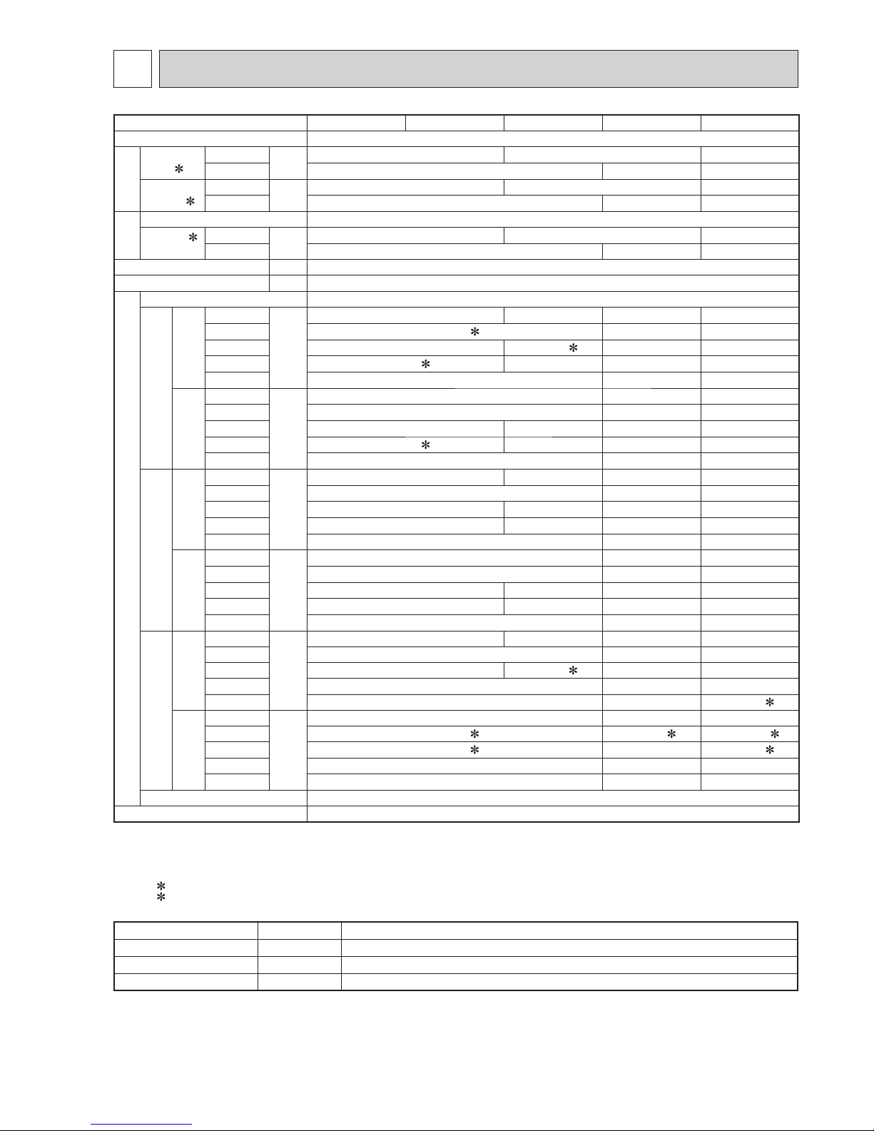
Indoor model MSZ-GE22VA MSZ-GE25VA MSZ-GE35VA MSZ-GE42VA MSZ-GE50VA
Power supply Single phase 230 V, 50 Hz
Electrical
data
Power
input 1
Cooling
W
22 29
43
Heating 23
30 39
Running
current 1
Cooling
A
0.22 0.29
0.39
Heating 0.23
0.31 0.36
Fan
motor
Model RC0J40-FK
Current
1
Cooling
A
0.22 0.29
0.39
Heating 0.23 0.31 0.36
Dimensions W × H × D mm 798 × 295 × 232
Weight kg
10
Special remarks
Air direction 5
Airfl ow
Cooling
Super High
m
3
/h
678
762 768 906
High
546 (552 2)
624 714
Med.
402 402 (414 2)
516 576
Low
288 (276 2) 288
408 468
Silent
246
348 390
Heating
Super High
m
3
/h
690 786 870
High
546 624 732
Med.
396 402 516 576
Low
288 (276 2) 288 420 468
Silent
246 348 390
Sound level
Cooling
Super High
dB(A)
42
43 46 49
High
36
40 44
Med.
29
30 35 38
Low
21
22 30 33
Silent
19
26 28
Heating
Super High
dB(A)
42 46 48
High
36 40 43
Med.
29 30 35 37
Low
21 22 30 33
Silent
19 26 28
Fan speed
Cooling
Super High
rpm
1,020 1,120 1,120 1,280
High 860 950 1,060
Med. 670 670 (690
2) 810 890
Low 530 680 750
Silent 470 600 650 (690 2)
Heating
Super High
rpm
1,040 1,140 1,240
High 860 (700 2) 950 (930 2) 1,080 (930 2)
Med. 670 (610
2) 810 890 (840 2)
Low 530
690 750
Silent 470
600 650
Fan speed regulator 5
Remote controller model KM09A
NOTE: Test conditions are based on ISO 5151.
Cooling: Indoor Dry-bulb temperature 27°C Wet-bulb temperature 19°C
Outdoor Dry-bulb temperature 35°C
Heating: Indoor Dry-bulb temperature 20°C
Outdoor Dry-bulb temperature 7°C Wet-bulb temperature 6°C
1 Measured under rated operating frequency.
2 For multi system.
Specifications and rating conditions of main electric parts
Fuse
(
F11)
T3.15AL250V
Horizontal vane motor (MV) 12 VDC
Varistor (NR11) S10K300E3K1 (ERZV14D471)
Terminal block
(TB)
3P
SPECIFICATION
3
Mitsubishi ilmalämpöpumput huoltaa ja korjaa: Jäähdytinpalvelu RefGroup Oy
www.ilmalämpöpumput.com
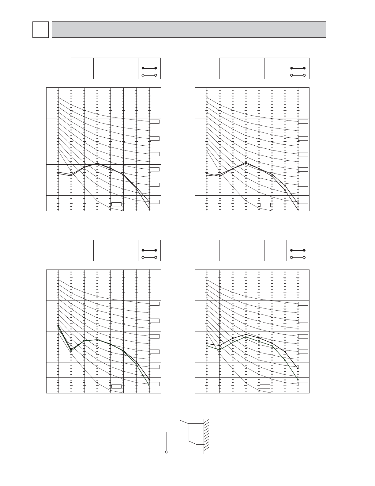
6
MSZ-GE22VA MSZ-GE25VA
90
80
70
60
50
40
30
20
10
63 125 250 500 1000 2000 4000 8000
NC-60
NC-50
NC-40
NC-30
NC-20
NC-70
OCTAVE BAND SOUND PRESSURE LEVEL, dB re 0.0002 MICRO BAR
BAND CENTER FREQUENCIES, Hz
COOLING
FUNCTION
SPL(dB(A))
LINE
Super High
FAN SPEED
HEATING
43
42
NC-10
MSZ-GE35VA
Test conditions
Cooling: Dry-bulb temperature 27°C
Wet-bulb temperature 19°C
Heating: Dry-bulb temperature 20°C
INDOOR UNIT
WALL
MICROPHONE
0.8m
1m
90
80
70
60
50
40
30
20
10
63 125 250 500 1000 2000 4000 8000
NC-60
NC-50
NC-40
NC-30
NC-20
NC-70
OCTAVE BAND SOUND PRESSURE LEVEL, dB re 0.0002 MICRO BAR
BAND CENTER FREQUENCIES, Hz
COOLING
FUNCTION
SPL(dB(A))
LINE
Super High
FAN SPEED
HEATING
42
42
NC-10
NOISE CRITERIA CURVES
4
MSZ-GE42VA
90
80
70
60
50
40
30
20
10
63 125 250 500 1000 2000 4000 8000
NC-60
NC-50
NC-40
NC-30
NC-20
NC-70
OCTAVE BAND SOUND PRESSURE LEVEL, dB re 0.0002 MICRO BAR
BAND CENTER FREQUENCIES, Hz
COOLING
FUNCTION
SPL(dB(A))
LINE
Super High
FAN SPEED
HEATING
49
48
NC-10
MSZ-GE50VA
90
80
70
60
50
40
30
20
10
63 125 250 500 1000 2000 4000 8000
NC-60
NC-50
NC-40
NC-30
NC-20
NC-70
OCTAVE BAND SOUND PRESSURE LEVEL, dB re 0.0002 MICRO BAR
BAND CENTER FREQUENCIES, Hz
COOLING
FUNCTION
SPL(dB(A))
LINE
Super High
FAN SPEED
HEATING
46
46
NC-10
Mitsubishi ilmalämpöpumput huoltaa ja korjaa: Jäähdytinpalvelu RefGroup Oy
www.ilmalämpöpumput.com
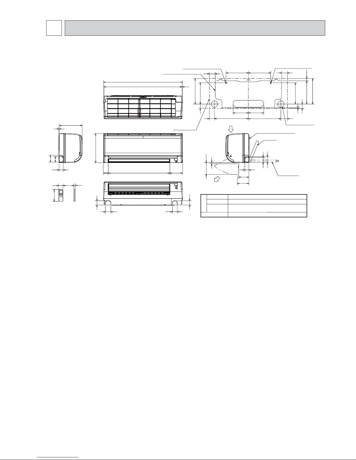
7
Unit: mm
MSZ-GE22VA MSZ-GE25VA MSZ-GE35VA MSZ-GE42VA MSZ-GE50VA
211.5
231.5
253
21.5
155 155
80
80
225 225
3
19
159
58
5
232
56
69
798
785 6.5
13061950
295
50
42
56
43
42
8
100
107
112
45
56
69
33861
212.5
254
41
42
315 84
11×26 Oblong hole
11×20 Oblong hole
Installation plate
Indoor unit
Wall hole ø65
Air in
Air out
Installation plate
Piping
Drain hose
Piping
Insulation ø35 O.D
Liquid line ø6.35 - 0.5 m (Flared connection ø6.35)
Gas line ø9.52 - 0.43 m
(Flared connection: ø9.52 (22/25/35/42), ø12.7 (50))
Drain hose Insulation ø28 O.D Connected part ø16 O.D
OUTLINES AND DIMENSIONS
5
Mitsubishi ilmalämpöpumput huoltaa ja korjaa: Jäähdytinpalvelu RefGroup Oy
www.ilmalämpöpumput.com
8
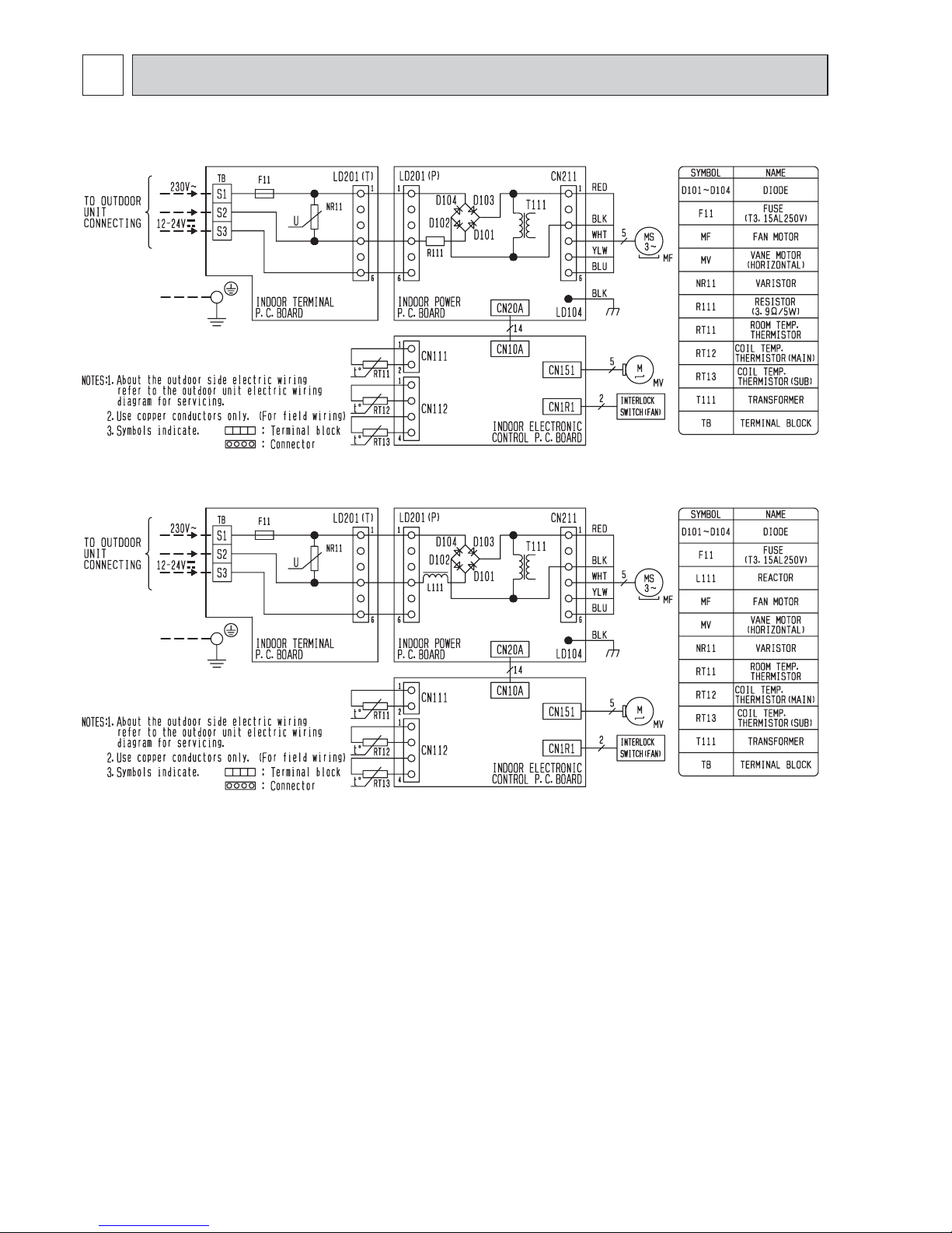
MSZ-GE22VA MSZ-GE25VA MSZ-GE35VA
WIRING DIAGRAM
6
MSZ-GE42VA MSZ-GE50VA
Mitsubishi ilmalämpöpumput huoltaa ja korjaa: Jäähdytinpalvelu RefGroup Oy
www.ilmalämpöpumput.com
9
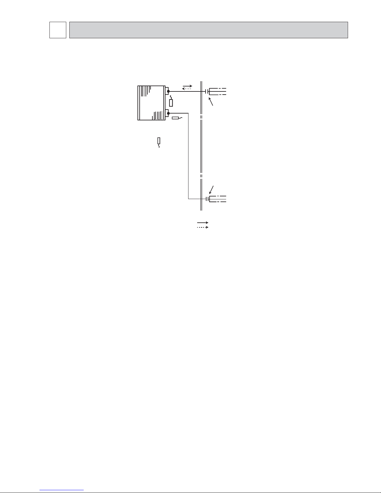
Indoor
heat
exchanger
Flared connection
Room temperature
thermistor
RT11
Flared connection
Refrigerant pipe ø9.52 (GE22/25/35/42)
ø12.7 (GE50)
(with heat insulator)
Refrigerant pipe ø6.35
(with heat insulator)
Indoor coil
thermistor
RT12 (main)
Indoor coil
thermistor
RT13 (sub)
Refrigerant flow in cooling
Refrigerant flow in heating
Unit: mm
MSZ-GE22VA MSZ-GE25VA MSZ-GE35VA MSZ-GE42VA MSZ-GE50VA
REFRIGERANT SYSTEM DIAGRAM
7
Mitsubishi ilmalämpöpumput huoltaa ja korjaa: Jäähdytinpalvelu RefGroup Oy
www.ilmalämpöpumput.com
10
8-1. TIMER SHORT MODE
For service, set time can be shortened by short circuit of JPG and JPS on the electronic control P.C. board.
The time will be shortened as follows. (Refer to 10-7.2.)
Set time: 1 minute → 1 second
Set time: 3 minutes → 3 seconds (It takes 3 minutes for the compressor to start operation. However, the starting time is
shortened by short circuit-of JPG and JPS.)
8-2. P.C. BOARD MODIFICATION FOR INDIVIDUAL OPERATION
A maximum of 4 indoor units with wireless remote controllers can be used in a room.
In this case, to operate each indoor unit individually by each remote controller, P.C. boards of remote controller must be
modified according to the number of the indoor unit.
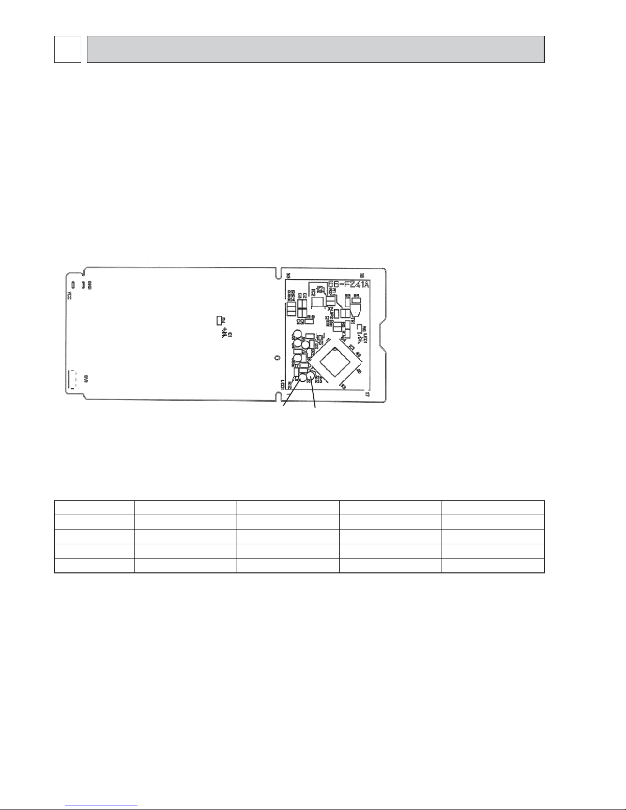
How to modify the remote controller P.C. board
Remove batteries before modification.
The board has a print as shown below:
The P.C. board has the print “J1” and “J2”. Solder “J1” and “J2” according to the number of indoor unit as shown in Table 1.
After modification, press the RESET button.
NOTE: For modification, take out
the batteries and press
the OPERATE/STOP (ON/
OFF) button twice or 3
times at first.
After modification, put back
the batteries then press the
RESET button.
J2
J1
Table 1
1 unit operation 2 units operation 3 units operation 4 units operation
No. 1 unit No modifi cation Same as at left Same as at left Same as at left
No. 2 unit — Solder J1 Same as at left Same as at left
No. 3 unit — — Solder J2 Same as at left
No. 4 unit — — — Solder both J1 and J2
How to set the remote controller exclusively for particular indoor unit
After you turn the breaker ON, the first remote controller that sends the signal to the indoor unit will be regarded as the remote
controller for the indoor unit.
The indoor unit will only accept the signal from the remote controller that has been assigned to the indoor unit once they are
set.
The setting will be cancelled if the breaker is turned OFF, or the power supply is shut down.
Please conduct the above setting once again after the power has restored.
MSZ-GE22VA MSZ-GE25VA MSZ-GE35VA MSZ-GE42VA MSZ-GE50VA
SERVICE FUNCTIONS
8
Mitsubishi ilmalämpöpumput huoltaa ja korjaa: Jäähdytinpalvelu RefGroup Oy
www.ilmalämpöpumput.com
11
8-3. AUTO RESTART FUNCTION
When the indoor unit is controlled with the remote controller, the operation mode, the set temperature, and the fan speed
are memorized by the indoor electronic control P.C. board. “AUTO RESTART FUNCTION” automatically starts operation
in the same mode just before the shutoff of the main power.
Operation
If the main power has been cut, the operation settings remain.
After the power is restored, the unit restarts automatically according to the memory.
(However, it takes at least 3 minutes
for the compressor to start running.)
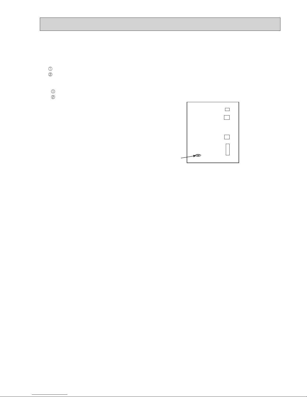
How to release “AUTO RESTART FUNCTION”
Turn off the main power for the unit.
Solder the jumper wire to JR07 on the indoor electronic control P.C. board. (Refer to 10-7.2.)
NOTE:
• The operation settings are memorized when 10 seconds have passed after the indoor unit was operated with the remote
controller.
• If main power is turned OFF or a power failure occurs while AUTO START/STOP timer is active, the timer setting is can-
celled.
• If the unit has been off with the remote controller before power failure, the auto restart function does not work as the
power button of the remote controller is OFF.
• To prevent breaker OFF due to the rush of starting current, systematize other home appliance not to turn ON at the same
time.
• When some air conditioners are connected to the same supply system, if they are operated before power failure, the
starting current of all the compressors may flow simultaneously at restart.
Therefore, the special counter-measures are required to prevent the main voltage-drop or the rush of the starting current
by adding to the system that allows the units to start one by one.
CN 111CN112CN151CN10A
Indoor electronic
control P.C. board
JR07
Mitsubishi ilmalämpöpumput huoltaa ja korjaa: Jäähdytinpalvelu RefGroup Oy
www.ilmalämpöpumput.com
 Loading...