How it Works
Log In / Sign Up
Buy Points
How it Works
FAQ
Contact Us
Questions and Suggestions
Users
Mitsubishi Electric
Loading...
M
MXZ2C20NA2
MXZ30TN
MXZ30TN2
MXZ3A54VA
5
MXZ4A71VA
4
MXZ4A80VA
6
MXZ-4D72VA- E1
MXZ-4D80VA
MXZ-4D83VA
5
MXZ-4D83VA-E1
MXZ-4E72VA
3
MXZ-4E72VA-E1
MXZ-4E72VA-ER1
MXZ-4E72VA-ET1
MXZ-4E80VAD
MXZ-4E83VA
3
MXZ-4E83VA-E1
MXZ-4E83VA-E2
MXZ-4E83VA-E3
MXZ-4E83VA-ER1
MXZ-4E83VA-ER2
MXZ-4E83VA-ET1
MXZ-4E83VA-ET2
MXZ-4E83VA-ET3
MXZ-4E83VAHZ
2
MXZ-4F72VF
2
MXZ-4F72VF-E1
MXZ-4F72VF-ET1
MXZ-5A100VA
2
MXZ-5A100VA - E1
MXZ-5B100VA
5
MXZ-5B100VA-E1
3
MXZ-5B42NA
2
MXZ-5C100VA
7
MXZ-5C100VA2
2
MXZ-5C100VA - E1
MXZ-5C42NA
2
MXZ-5C42NA2-U1
MXZ-5C42NAHZ
6
MXZ-5C42NAHZ-U1
2
MXZ-5D100VA
MXZ-5D102VA
5
MXZ-5D102VA-E1
MXZ-5E100VAD
MXZ-5E102VA
2
MXZ-5E102VA - E1
MXZ-5E102VA-E2
MXZ-5E102VA-E3
MXZ-5E102VA-ER1
MXZ-5E102VA-ET1
MXZ-5E102VA-ET2
MXZ-5E102VA-ET3
MXZ-6C120VA
6
MXZ-6C120VA - E1
MXZ-6C122VA
4
MXZ-6D120VA
MXZ-6D122VA
3
MXZ-8A140A
MXZ-8A140VA
7
MXZ-8A140VA1
MXZ-8A140VA2
MXZ-8A140VA3
MXZ-8A140VA/VA1/VA2/VA3
MXZ-8B140
MXZ-8B140/160VA/YA
MXZ-8B140VA
3
MXZ-8B140VA-A
MXZ-8B140YA
3
MXZ-8B160VA
3
MXZ-8B160YA
3
MXZ-8B48NA
4
MXZ-8B48NAR1
MXZ-8C48NA
6
MXZ-8C48NAHZ
6
MXZ-8C48NAHZ-U1
2
MXZ-8C48NA-U1
2
MXZ-8C60NA
MXZ-8C60NA-U1
2
MXZ-A14WV
MXZ-A14WV-E1
MXZ-A18WV
2
MXZ-A18WV-E1
MXZ-A26
MXZ-A26/32WV
MXZ-A26WV
4
MXZ-A26WV-E1
MXZ-A32WV
5
MXZ-A32WV-E1
MXZ-A•NA
2
MXZ-A·VA
MXZ-C-NA
MXZ-C-NAHZ
MXZ-F-VF
MYA-EU
MYE-EU
MYSTRAL
MZ360135EX
MZ360216EX
MZ360217EX
MZ360229EX
Loading...
Loading...
Nothing found
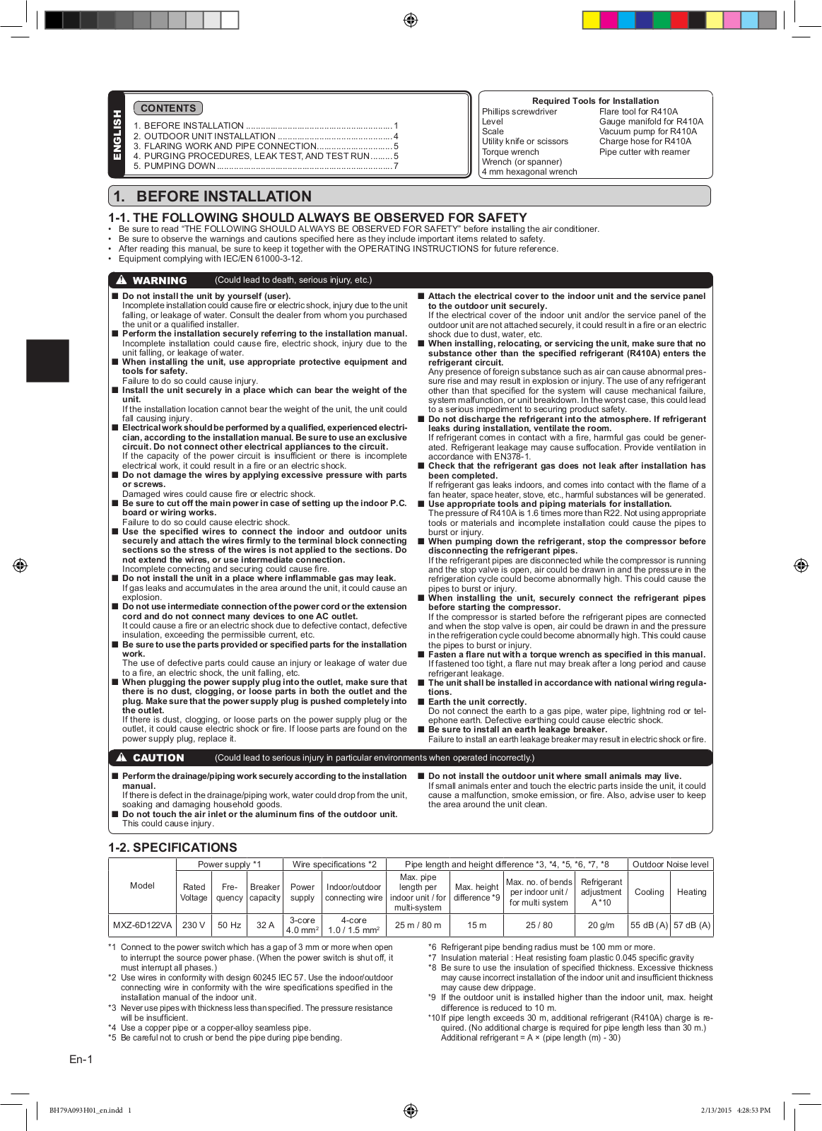
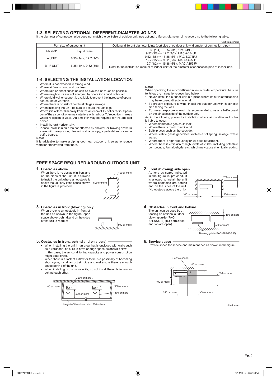
MXZ-6D122VA
Installation Manual
9 pgs
2.29 Mb
0
Installation Manual
9 pgs
1.86 Mb
0
Service Manual
542 pgs
22.75 Mb
0
Table of contents
Loading...
Mitsubishi Electric MXZ-6D122VA Installation Manual
...
Mitsubishi Electric Installation Manual
Download
Specifications and Main Features
Frequently Asked Questions
User Manual
Download
Loading...
+
6
hidden pages
Unhide
You need points to download manuals.
1 point = 1 manual.
You can buy points or you can get point for every manual you upload.
Buy points
Upload your manuals