

Mitsubishi MXZ-4C71VA, MXZ-2C52VA, MXZ-4C80VA, MXZ-2C40VA, MXZ-4C80VA2 Service Manual
...
SERVICE MANUAL
CONTENTS
1. TECHNICAL CHANGES ···································3
2. PART NAMES AND FUNCTIONS ····················· 4
3. SPECIFICATION ················································ 5
4. NOISE CRITERIA CURVES ···························· 15
5. OUTLINES AND DIMENSIONS ······················ 18
6. WIRING DIAGRAM ·········································· 24
7. REFRIGERANT SYSTEM DIAGRAM ············· 38
8. PERFORMANCE CURVES ····························· 48
9. ACTUA TOR CONTROL ··································· 79
10. SERVICE FUNCTIONS ···································· 80
11. TROUBLESHOOTING ····································· 84
12. DISASSEMBLY INSTRUCTIONS ···················118
INDOOR UNITS COMBINATION SHEETS
Models
No. OBH584
REVISED EDITION-G
HFC
utilized
R410A
SPLIT-TYPE AIR CONDITIONERS
MXZ-4C80VA
MXZ-5C100VA
OUTDOOR UNIT
Indoor unit service manual
MSZ-FD•VA Series (OBH488)
MSZ-FH•VE Series (OBH623)
MSZ-GE•VA Series (OBH515)
MSZ-EF•VE Series (OBH589)
MSZ-SF•VA Series (OBH555)
MSZ-SF•VE Series (OBH600)
MFZ-KA•VA Series (OB409)
MFZ-KJ•VA Series (OBH666)
MLZ-KA•VA Series (OBH483)
SLZ-KA•VA Series (OC320)
SEZ-KD•VA(L) Series (HWE07110)
PLA-RP•BA Series (OCH412)
PCA-RP•KA Series (OCH454)
PEAD-RP•JA Series (HWE08130)
NOTE:
RoHS compliant products have <G> mark on the spec name plate.
PARTS CATALOG (OBB584)
MXZ-2C30VA
-
E1
MXZ-2C40VA
-
E1
MXZ-2C52VA
-
E1
MXZ-3C54VA
-
E1
MXZ-3C68VA
-
E1
MXZ-4C71VA
-
E1
MXZ-4C80VA
-
E1
MXZ-4C80VA2
-
E1
MXZ-5C100VA
-
E1
MXZ-5C100VA2
-
E1
Please void OBH584 REVISED EDITION-F.
Revision G:
• MXZ-6C122VA- E2, -
ER2
have been
added.
MXZ-6C120VA
-
E1
,
-
E2
MXZ-6C122VA
-
E1
,
-
E2
,
-
ER1
,
-
ER2

2
<Preparation before the repair service>
Prepare the proper tools.
Prepare the proper protectors.
Provide adequate ventilation.
After stopping the operation of the air conditioner, turn off the power-supply breaker and remove the power plug.
Discharge the capacitor before the work involving the electric parts.
<Precautions during the repair service>
Do not perform the work involving the electric parts with wet hands.
Do not pour water into the electric parts.
Do not touch the refrigerant.
Do not touch the hot or cold areas in the refrigeration cycle.
When the repair or the inspection of the circuit needs to be done without turning off the power, exercise great caution not to
touch the live parts.
Revision A:
• MXZ-2C30VA- E1, MXZ-2C40VA- E1, and MXZ-2C52VA- E1 have been added.
Use the specifi ed refrigerant only
Never use any refrigerant other than that specified.
Doing so may cause a burst, an explosion, or fire when the unit is being used, serviced, or disposed of.
Correct refrigerant is specified in the manuals and on the spec labels provided with our products.
We will not be held responsible for mechanical failure, system malfunction, unit breakdown or accidents caused by
failure to follow the instructions.
Revision B:
• MXZ-6C120VA- E2 has been added.
• FAILURE MODE RECALL FUNCTION has been corrected.
Revision C:
• MXZ-4C80VA2- E1 and MXZ-5C100VA2- E1 have been added.
Revision D:
• MXZ-6C122VA- E1 has been added.
Revision E:
• INDOOR UNITS COMBINATION SHEETS for MXZ-6C122VA- E1 have been added.
Revision F:
• MXZ-6C122VA-
ER1
has been added.
Revision G:
• MXZ-6C122VA- E2, -
ER2
have been added.
OBH584G
3
TECHNICAL CHANGES
1
MXZ-3B54VA -
E1
MXZ-3C54VA -
E1
MXZ-3B68VA -
E1
MXZ-3C68VA -
E1
MXZ-4B71VA -
E1
MXZ-4C71VA -
E1
MXZ-4B80VA -
E1
MXZ-4C80VA -
E1
MXZ-5A100VA -
E1
MXZ-5C100VA -
E1
1. Indoor units combinations have been added (MSZ-EF Series).
2. Outdoor fan motor has been changed.
MXZ-6C120VA -
E1
1. New model
MXZ-2B30VA -
E1
MXZ-2C30VA -
E1
1. Indoor units combinations have been added (MSZ-EF Series).
2. Muffler has been added.
MXZ-2B40VA -
E1
MXZ-2C40VA -
E1
1. Indoor units combinations have been added (MSZ-EF Series).
2. Muffler has been added.
MXZ-2B52VA -
E1
MXZ-2C52VA -
E1
1. Indoor units combinations have been added (MSZ-EF Series).
2. Muffler has been added.
MXZ-6C120VA -
E1
MXZ-6C120VA -
E2
1. Accumulator has been added.
2. Power receiver has been removed.
3. Model name of compressor has been changed.
4. Control P.C. board has been changed.
MXZ-4C80VA -
E1
MXZ-4C80VA2 -
E1
1. Front panel has been changed.
2. Grille has been changed.
3. Grille roof has been added.
4. Service panel has been changed.
5. Base has been changed.
6. Rear guard has been changed.
7. Drain socket has been changed.
8. Unit size has been changed. (W x H x D: 900 x 900 x 320
900 x 915 x 320)
9. Weight of the unit has been changed. (67 kg 69 kg)
MXZ-5C100VA -
E1
MXZ-5C100VA2 -
E1
1. Front panel has been changed.
2. Grille has been changed.
3. Grille roof has been added.
4. Service panel has been changed.
5. Base has been changed.
6. Rear guard has been changed.
7. Drain socket has been changed.
8. Unit size has been changed. (W x H x D: 900 x 900 x 320
900 x 915 x 320)
9. Weight of the unit has been changed. (68 kg 70 kg)
MXZ-6C120VA -
E2
MXZ-6C122VA -
E1
1. Outdoor control P.C. board has been changed.
MXZ-6C122VA -
ER1
1. New model
MXZ-6C122VA -
E1
MXZ-6C122VA -
E2
1. Indoor units combinations have been added (MFZ-KJ series).
MXZ-6C122VA -
ER1
MXZ-6C122VA -
ER2
1. Indoor units combinations have been added (MFZ-KJ series).
OBH584G
4
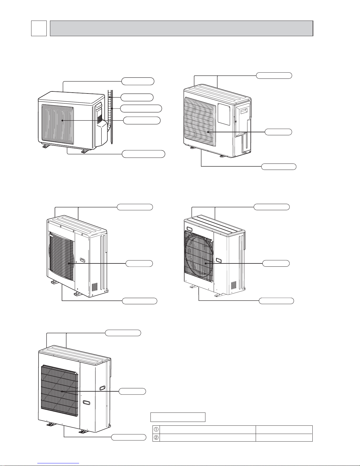
PART NAMES AND FUNCTIONS
2
ACCESSORIES
Drain socket
Drain cap (MXZ-3C/4C/5C)
1
2
MXZ-4C80VA
MXZ-5C100VA
Air outlet
Drain outlet
Air inlet
(Back and side)
Air outlet
Drain outlet
Air inlet
(Back and side)
MXZ-3C54VA
MXZ-3C68VA
MXZ-4C71VA
MXZ-6C120VA
MXZ-6C122VA
Air outlet
Drain outlet
Air inlet
(Back and side)
MXZ-2C30VA
MXZ-2C40VA
MXZ-2C52VA
Air inlet
Air outlet
Drain outlet
Piping
Drain hose
(Back and side)
MXZ-4C80VA2
MXZ-5C100VA2
Air outlet
Drain outlet
Air inlet
(Back and side)
OBH584G
5
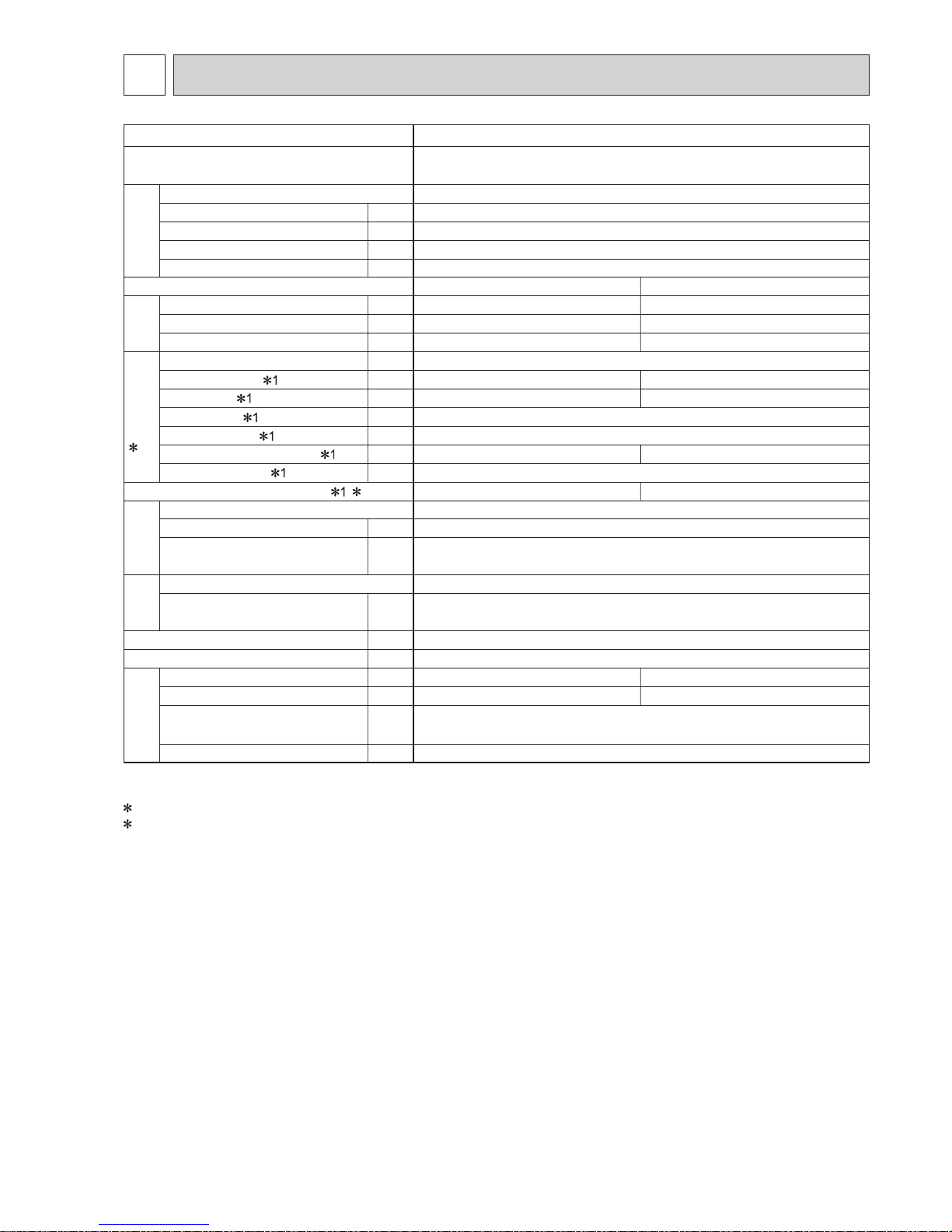
SPECIFICATION
3
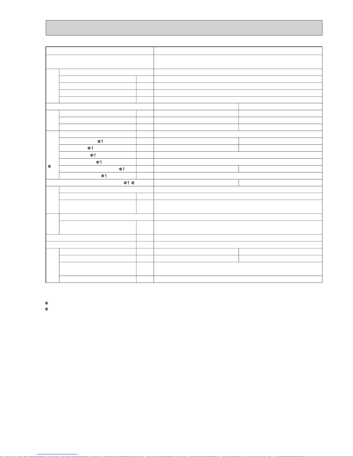
Outdoor model
Indoor units number
Piping total length
Connecting pipe length
Height difference (Indoor ~ Outdoor)
Height difference (Indoor ~ Indoor)
Function
Capacity [Rated (Min.-Max.) Hz]
Dehumidification
Outdoor air flow
Breaker capacity
Running current
Power input
Power factor
Starting current
Compressor motor current
Fan motor current
Model
Output
Winding
resistance (at 20 °C)
Model
Winding
resistance (at 20 °C)
Dimensions W x H x D
Weight
Sound level (High)
Fan speed (High)
Refrigerant filling
capacity (R410A)
Refrigeration oil (Model)
m
m
m
m
kW
L/h
m
3
/h
A
A
W
%
A
A
A
W
Ω
Ω
mm
kg
dB
rpm
kg
L
Compressor
2 Electrical
data
Fan
motor
Special
remarks
Capacity System
Coefficient of performance(C.O.P) 2
Outdoor unit power supply
MXZ-2C30VA
Single phase
230 V, 50 Hz
1 to 2
Max. 20
Max. 15
Refer to 7 REFRIGERANT SYSTEM DIAGRAM.
Refer to 7 REFRIGERANT SYSTEM DIAGRAM.
10
90
3.94
0.35
KNB073FGDHC
750
U-V 1.70
V-W 1.70 W-U 1.70
RC0J50-CF
BLK-WHT 14.2
WHT-RED 14.2 RED-BLK 14.2
800 x 550 x 285
33
1.15
0.32 (NEO22)
Cooling
3.0 (1.1 - 4.0)
—
1,974
2.71
560
2.36
5.36
46
860
Heating
4.0 (1.0 - 4.4)
—
1,878
3.94
815
3.59
4.91
47
820
COOLING INDOOR Dry-bulb temperature 27.0°C Wet-bulb temperature 19.0°C
OUTDOOR Dry-bulb temperature 35.0°C Wet-bulb temperature 24.0°C
HEATING INDOOR Dry-bulb temperature 20.0°C
OUTDOOR Dry-bulb temperature 7.0°C Wet-bulb temperature 6.0°C
1 Measured under rated operating frequency.
2 Electrical data is for only outdoor unit.
NOTE: Test conditions are based on ISO 5151. (Refrigerant piping length (one way): 5 m)
OBH584G

6
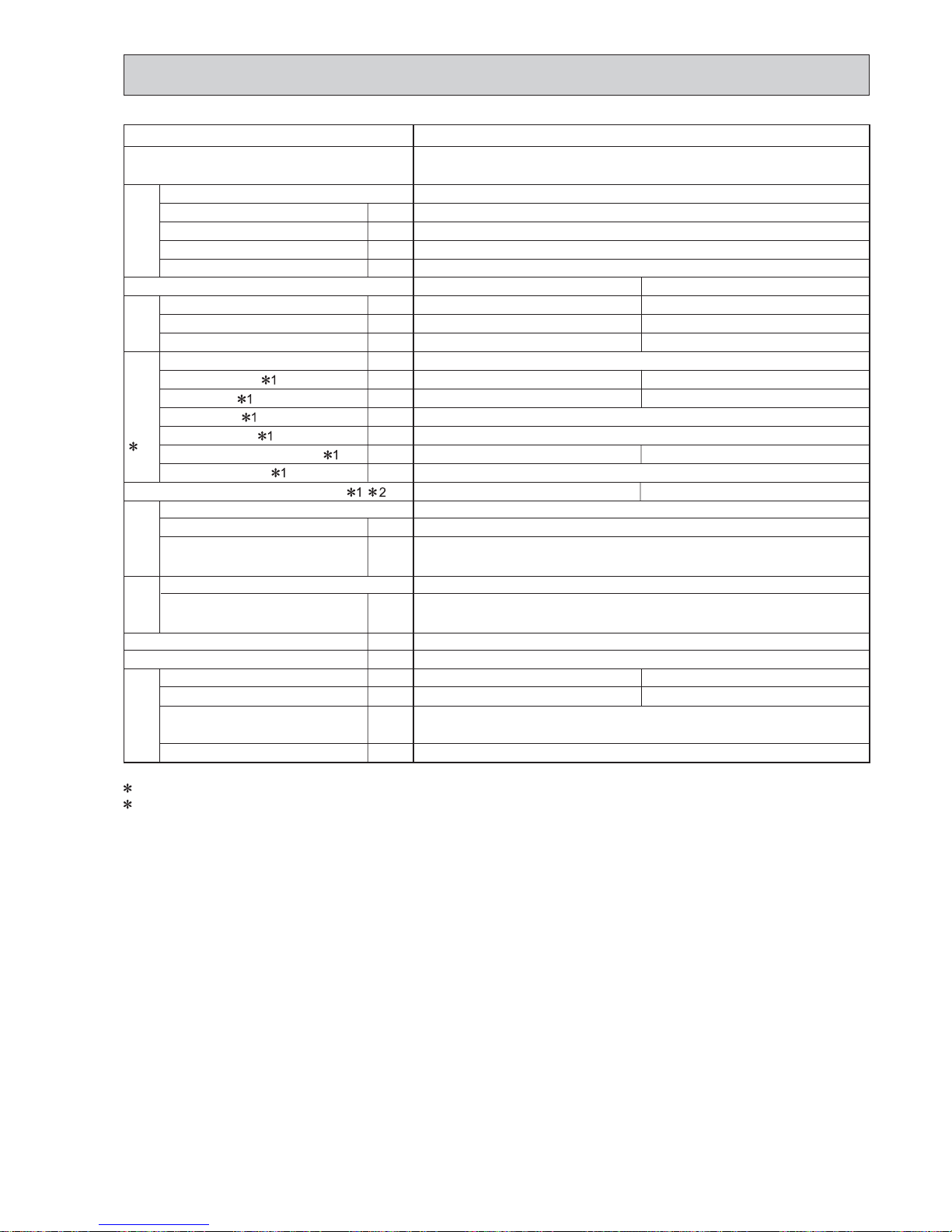
Outdoor model
Indoor units number
Piping total length
Connecting pipe length
Height difference (Indoor ~ Outdoor)
Height difference (Indoor ~ Indoor)
Function
Capacity [Rated (Min.-Max.) Hz]
Dehumidification
Outdoor air flow
Breaker capacity
Running current
Power input
Power factor
Starting current
Compressor motor current
Fan motor current
Model
Output
Winding
resistance (at 20 °C)
Model
Winding
resistance (at 20 °C)
Dimensions W x H x D
Weight
Sound level
Fan speed
Refrigerant filling
capacity (R410A)
Refrigeration oil (Model)
m
m
m
m
kW
L/h
m
3
/h
A
A
W
%
A
A
A
W
Ω
Ω
mm
kg
dB
rpm
kg
L
Compressor
2 Electrical
data
Fan
motor
Special
remarks
Capacity System
Coefficient of performance(C.O.P) 1 2
Outdoor unit power supply
MXZ-2C40VA
Single phase
230 V, 50 Hz
1 to 2
Max. 30
Max. 20
Refer to 7 REFRIGERANT SYSTEM DIAGRAM.
Refer to 7 REFRIGERANT SYSTEM DIAGRAM.
15
95
4.00
0.35
KNB092FFDHC
1,100
U-V 1.70
V-W 1.70 W-U 1.70
RC0J50-CF
BLK-WHT 14.2
WHT-RED 14.2 RED-BLK 14.2
800 x 550 x 285
35
1.3
0.32 (NEO22)
Cooling
4.0 (1.1 - 4.5)
—
1,752
4.00
875
3.65
4.57
47
840
Heating
4.5 (1.0 - 5.0)
—
1,596
3.98
870
3.60
5.17
48
770
COOLING INDOOR Dry-bulb temperature 27.0°C Wet-bulb temperature 19.0°C
OUTDOOR Dry-bulb temperature 35.0°C Wet-bulb temperature 24.0°C
HEATING INDOOR Dry-bulb temperature 20.0°C
OUTDOOR Dry-bulb temperature 7.0°C Wet-bulb temperature 6.0°C
1 Measured under rated operating frequency.
2 Electrical data is for only outdoor unit.
NOTE: Test conditions are based on ISO 5151. (Refrigerant piping length (one way): 5 m)
OBH584G
7
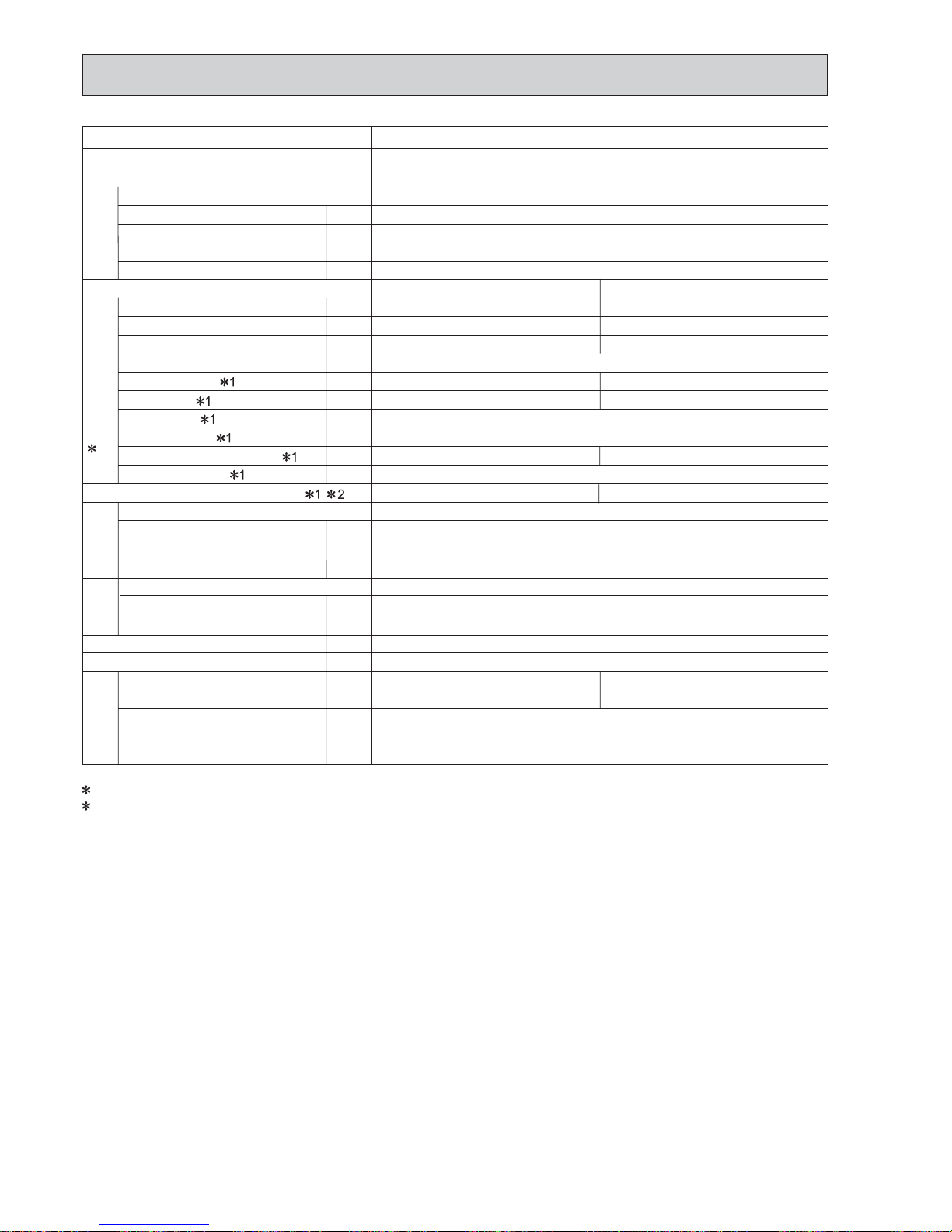
MXZ-2C52VA
Single phase
230 V, 50 Hz
1 to 2
Max. 30
Max. 20
Refer to 7 REFRIGERANT SYSTEM DIAGRAM.
Refer to 7 REFRIGERANT SYSTEM DIAGRAM.
15
97
7.22
0.35
SNB130FGBHT
1,400
U-V 0.98
V-W 0.98 W-U 0.98
RC0J50-CF
BLK-WHT 14.2
WHT-RED 14.2 RED-BLK 14.2
800 x 550 x 285
38
1.3
0.45 (NEO22)
Cooling
5.2 (1.1 - 6.0)
—
1,974
5.83
1,300
5.48
4.00
49
900
Heating
6.4 (1.0 - 7.0)
—
1,998
7.22
1,610
6.87
3.98
50
910
Outdoor model
Indoor units number
Piping total length
Connecting pipe length
Height difference (Indoor ~ Outdoor)
Height difference (Indoor ~ Indoor)
Function
Capacity [Rated (Min.-Max.) Hz]
Dehumidification
Outdoor air flow
Breaker capacity
Running current
Power input
Power factor
Starting current
Compressor motor current
Fan motor current
Model
Output
Winding
resistance (at 20 °C)
Model
Winding
resistance (at 20 °C)
Dimensions W x H x D
Weight
Sound level (High/Low)
Fan speed (High/Low)
Refrigerant filling
capacity (R410A)
Refrigeration oil (Model)
m
m
m
m
kW
L/h
m
3
/h
A
A
W
%
A
A
A
W
Ω
Ω
mm
kg
dB
rpm
kg
L
Compressor
2 Electrical
data
Fan
motor
Special
remarks
Capacity System
Coefficient of performance(C.O.P) 2
Outdoor unit power supply
COOLING INDOOR Dry-bulb temperature 27.0°C Wet-bulb temperature 19.0°C
OUTDOOR Dry-bulb temperature 35.0°C Wet-bulb temperature 24.0°C
HEATING INDOOR Dry-bulb temperature 20.0°C
OUTDOOR Dry-bulb temperature 7.0°C Wet-bulb temperature 6.0°C
1 Measured under rated operating frequency.
2 Electrical data is for only outdoor unit.
NOTE: Test conditions are based on ISO 5151. (Refrigerant piping length (one way): 5 m)
OBH584G

8
COOLING INDOOR Dry-bulb temperature 27.0°C Wet-bulb temperature 19.0°C
OUTDOOR Dry-bulb temperature 35.0°C Wet-bulb temperature 24.0°C
HEATING INDOOR Dry-bulb temperature 20.0°C
OUTDOOR Dry-bulb temperature 7.0°C Wet-bulb temperature 6.0°C
1 Measured under rated operating frequency.
2 Electrical data is for only outdoor unit.
NOTE: Test conditions are based on ISO 5151. (Refrigerant piping length (one way): 5 m)
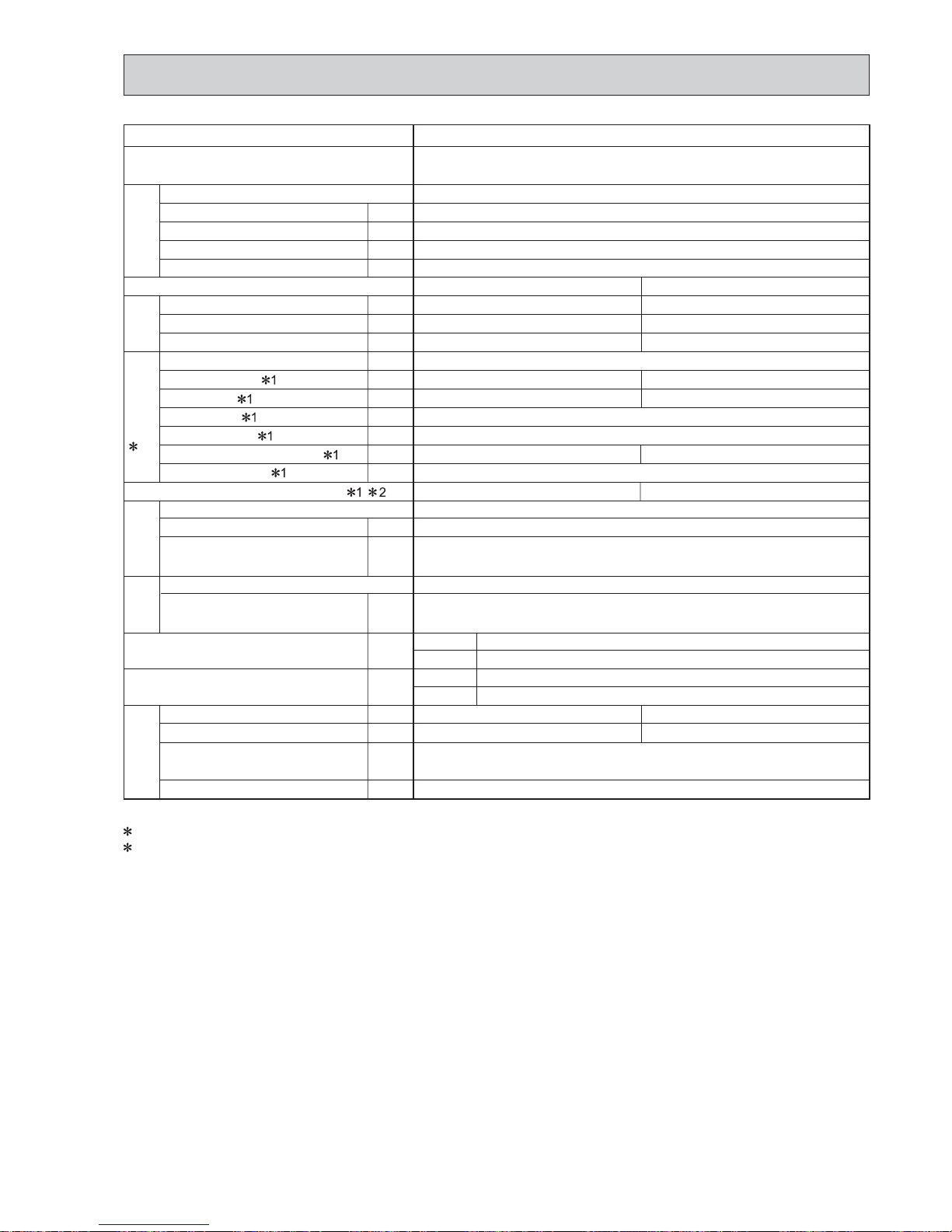
Outdoor model
Indoor units number
Piping total length
Connecting pipe length
Height difference (Indoor ~ Outdoor)
Height difference (Indoor ~ Indoor)
Function
Capacity [Rated (Min.-Max.) Hz]
Dehumidification
Outdoor air flow
Breaker capacity
Running current
Power input
Power factor
Starting current
Compressor motor current
Fan motor current
Model
Output
Winding
resistance (at 20 °C)
Model
Winding
resistance (at 20°C)
Dimensions W x H x D
Weight
Sound level
Fan speed
Refrigerant filling
capacity (R410A)
Refrigeration oil (Model)
m
m
m
m
kW
L/h
m
3
/h
A
A
W
%
A
A
A
W
Ω
Ω
mm
kg
dB
rpm
kg
L
Compressor
2 Electrical
data
Fan
motor
Special
remarks
Capacity System
Coefficient of performance(C.O.P)
MXZ-3C54VA
Single phase
230 V, 50 Hz
1 to 3
Max. 50
Max. 25
Refer to 7 REFRIGERANT SYSTEM DIAGRAM.
Refer to 7 REFRIGERANT SYSTEM DIAGRAM.
25
99
6.43
0.2
SNB130FGBH1T
1,400
U-V 0.98
V-W 0.98 W-U 0.98
RC0J60-CB
BLK-WHT 15.2
WHT-RED 15.2 RED-BLK 15.2
840 x 710 x 330
57
2.7
0.7 (NEO22)
Cooling
5.4 (2.9-6.8)
—
2,526
5.23
1,190
5.03
4.54
47
650
Heating
7.0 (2.6-9.0)
—
2,580
6.43
1,465
6.23
4.78
51
660
Outdoor unit power supply
OBH584G
9
COOLING INDOOR Dry-bulb temperature 27.0°C Wet-bulb temperature 19.0°C
OUTDOOR Dry-bulb temperature 35.0°C Wet-bulb temperature 24.0°C
HEATING INDOOR Dry-bulb temperature 20.0°C
OUTDOOR Dry-bulb temperature 7.0°C Wet-bulb temperature 6.0°C
1 Measured under rated operating frequency.
2 Electrical data is for only outdoor unit.
NOTE: Test conditions are based on ISO 5151. (Refrigerant piping length (one way): 5 m)
Outdoor model
Indoor units number
Piping total length
Connecting pipe length
Height difference (Indoor ~ Outdoor)
Height difference (Indoor ~ Indoor)
Function
Capacity [Rated (Min.-Max.) Hz]
Dehumidification
Outdoor air flow
Breaker capacity
Running current
Power input
Power factor
Starting current
Compressor motor current
Fan motor current
Model
Output
Winding
resistance (at 20 °C)
Model
Winding
resistance (at 20°C)
Dimensions W x H x D
Weight
Sound level
Fan speed
Refrigerant filling
capacity (R410A)
Refrigeration oil (Model)
m
m
m
m
kW
L/h
m
3
/h
A
A
W
%
A
A
A
W
Ω
Ω
mm
kg
dB
rpm
kg
L
Compressor
2 Electrical
data
Fan
motor
Special
remarks
Capacity System
Coefficient of performance(C.O.P)
MXZ-3C68VA
Single phase
230 V, 50 Hz
1 to 3
Max. 60
Max. 25
Refer to 7 REFRIGERANT SYSTEM DIAGRAM.
Refer to 7 REFRIGERANT SYSTEM DIAGRAM.
25
99
9.00
0.2
SNB172FEGH1T
1,800
U-V 0.72
V-W 0.72 W-U 0.72
RC0J60-CB
BLK-WHT 15.2
WHT-RED 15.2 RED-BLK 15.2
840 x 710 x 330
57
2.7
0.7 (NEO22)
Cooling
6.8 (2.9-8.4)
—
2,526
7.80
1,775
7.60
3.83
48
650
Heating
8.6 (2.6-10.6)
—
2,580
9.00
2,050
8.80
4.20
52
660
Outdoor unit power supply
OBH584G
10
COOLING INDOOR Dry-bulb temperature 27.0°C Wet-bulb temperature 19.0°C
OUTDOOR Dry-bulb temperature 35.0°C Wet-bulb temperature 24.0°C
HEATING INDOOR Dry-bulb temperature 20.0°C
OUTDOOR Dry-bulb temperature 7.0°C Wet-bulb temperature 6.0°C
1 Measured under rated operating frequency.
2 Electrical data is for only outdoor unit.
NOTE: Test conditions are based on ISO 5151. (Refrigerant piping length (one way): 5 m)
Outdoor model
Indoor units number
Piping total length
Connecting pipe length
Height difference (Indoor ~ Outdoor)
Height difference (Indoor ~ Indoor)
Function
Capacity [Rated (Min.-Max.) Hz]
Dehumidification
Outdoor air flow
Breaker capacity
Running current
Power input
Power factor
Starting current
Compressor motor current
Fan motor current
Model
Output
Winding
resistance (at 20 °C)
Model
Winding
resistance (at 20°C)
Dimensions W x H x D
Weight
Sound level
Fan speed
Refrigerant filling
capacity (R410A)
Refrigeration oil (Model)
m
m
m
m
kW
L/h
m
3
/h
A
A
W
%
A
A
A
W
Ω
Ω
mm
kg
dB
rpm
kg
L
Compressor
2 Electrical
data
Fan
motor
Special
remarks
Capacity System
Coefficient of performance(C.O.P)
MXZ-4C71VA
Single phase
230 V, 50 Hz
1 to 4
Max. 60
Max. 25
Refer to 7 REFRIGERANT SYSTEM DIAGRAM.
Refer to 7 REFRIGERANT SYSTEM DIAGRAM.
25
99
7.49
0.2
SNB172FEGH1T
2,000
U-V 0.72
V-W 0.72 W-U 0.72
RC0J60-CB
BLK-WHT 15.2
WHT-RED 15.2 RED-BLK 15.2
840 x 710 x 330
58
2.7
0.7 (NEO22)
Cooling
7.1 (3.7-8.8)
—
2,526
7.38
1,680
7.18
4.23
48
650
Heating
8.6 (3.4-10.7)
—
2,580
7.49
1,705
7.29
5.04
52
660
Outdoor unit power supply
OBH584G
11
COOLING INDOOR Dry-bulb temperature 27.0°C Wet-bulb temperature 19.0°C
OUTDOOR Dry-bulb temperature 35.0°C Wet-bulb temperature 24.0°C
HEATING INDOOR Dry-bulb temperature 20.0°C
OUTDOOR Dry-bulb temperature 7.0°C Wet-bulb temperature 6.0°C
1 Measured under rated operating frequency.
2 Electrical data is for only outdoor unit.
NOTE: Test conditions are based on ISO 5151. (Refrigerant piping length (one way): 5 m)
Outdoor model
Indoor units number
Piping total length
Connecting pipe length
Height difference (Indoor ~ Outdoor)
Height difference (Indoor ~ Indoor)
Function
Capacity [Rated (Min.-Max.) Hz]
Dehumidification
Outdoor air flow
Breaker capacity
Running current
Power input
Power factor
Starting current
Compressor motor current
Fan motor current
Model
Output
Winding
resistance (at 20 °C)
Model
Winding
resistance (at 20°C)
Dimensions W x H x D
Weight
Sound level
Fan speed
Refrigerant filling
capacity (R410A)
Refrigeration oil (Model)
m
m
m
m
kW
L/h
m
3
/h
A
A
W
%
A
A
A
W
Ω
Ω
mm
kg
dB
rpm
kg
L
Compressor
2 Electrical
data
Fan
motor
Special
remarks
Capacity System
Coefficient of performance(C.O.P)
MXZ-4C80VA MXZ-4C80VA2
Single phase
230 V, 50 Hz
1 to 4
Max. 70
Max. 25
Refer to 7 REFRIGERANT SYSTEM DIAGRAM.
Refer to 7 REFRIGERANT SYSTEM DIAGRAM.
25
99
8.59
0.2
TNB220FMCH
2,100
U-V 1.41
V-W 1.41 W-U 1.41
RC0J60-CA
BLK-WHT 15.2
WHT-RED 15.2 RED-BLK 15.2
900 x 900 x 320
900 x 915 x 320
67
69
3.5
0.87 (NEO22)
Cooling
8.0 (3.7-9.2)
—
2,526
8.59
1,955
8.39
4.09
46
560
Heating
9.4 (3.4-11.6)
—
2,628
8.48
1,930
8.28
4.87
48
580
Outdoor unit power supply
4C80VA
4C80VA2
4C80VA
4C80VA2
OBH584G
12
COOLING INDOOR Dry-bulb temperature 27.0°C Wet-bulb temperature 19.0°C
OUTDOOR Dry-bulb temperature 35.0°C Wet-bulb temperature 24.0°C
HEATING INDOOR Dry-bulb temperature 20.0°C
OUTDOOR Dry-bulb temperature 7.0°C Wet-bulb temperature 6.0°C
1 Measured under rated operating frequency.
2 Electrical data is for only outdoor unit.
NOTE: Test conditions are based on ISO 5151. (Refrigerant piping length (one way): 5 m)
Outdoor model
Indoor units number
Piping total length
Connecting pipe length
Height difference (Indoor ~ Outdoor)
Height difference (Indoor ~ Indoor)
Function
Capacity [Rated (Min.-Max.) Hz
Dehumidification
Outdoor air flow
Breaker capacity
Running current
Power input
Power factor
Starting current
Compressor motor current
Fan motor current
Model
Output
Winding
resistance(at 20 °C)
Model
Winding
resistance(at 20 °C)
Dimensions W x H x D
Weight
Sound level
Fan speed
Refrigerant filling
capacity(R410A)
Refrigeration oil (Model)
m
m
m
m
kW
L/h
m
3
/h
A
A
W
%
A
A
A
W
Ω
Ω
mm
kg
dB
rpm
kg
L
Compressor
2 Electrical
data
Fan
motor
Special
remarks
Capacity System
Coefficient of performance(C.O.P)
Outdoor unit power supply
MXZ-5C100VA MXZ-5C100VA2
Single phase
230 V, 50 Hz
1 to 5
Max. 80
Max. 25
Refer to 7 REFRIGERANT SYSTEM DIAGRAM.
Refer to 7 REFRIGERANT SYSTEM DIAGRAM.
25
99
12.45
0.2
TNB220FMCH
2,700
U-V 1.41
V-W 1.41 W-U 1.41
RC0J60-CA
BLK-WHT 15.2
WHT-RED 15.2 RED-BLK 15.2
900 x 900 x 320
900 x 915 x 320
68
70
4.0
0.87 (NEO22)
Cooling
10.0 (3.9 - 11.0)
—
3,396
12.30
2,800
12.1
3.57
51
720
Heating
12.0 (4.1 - 14.0)
—
3,558
12.45
2,835
12.25
4.23
54
750
5C100VA
5C100VA2
5C100VA
5C100VA2
OBH584G
13
Outdoor model
Indoor units number
Piping total length
Connecting pipe length
Height difference (Indoor ~ Outdoor)
Height difference (Indoor ~ Indoor)
Function
Capacity [Rated (Min.-Max.) Hz
Dehumidification
Outdoor air flow
Breaker capacity
Running current
Power input
Power factor
Starting current
Compressor motor current
Fan motor current
Model
Output
Winding
resistance(at 20 °C)
Model
Dimensions W x H x D
Weight
Sound level
Fan speed
Refrigerant filling
capacity(R410A)
Refrigeration oil (Model)
m
m
m
m
kW
L/h
m
3
/h
A
A
W
%
A
A
A
W
Ω
mm
kg
dB
rpm
kg
L
Compressor
2 Electrical
data
Fan
motor
Special remarks
Capacity System
Coefficient of performance(C.O.P)
E1
Outdoor unit power supply
MXZ-6C120VA
Single phase
230 V, 50 Hz
2 to 6
Max. 80
Max. 25
Refer to 7 REFRIGERANT SYSTEM DIAGRAM.
Refer to 7 REFRIGERANT SYSTEM DIAGRAM.
32
99
15.85
0.3
TNB306FPGM3
TNB306FPGM2
3,000
U-V 0.53
V-W 0.53 W-U 0.53
SIC-81FW-D888
900 x 1,070 x 320
88
87
5.0
4.8
1.61 (FV50S)
1.07 (FV50S)
Cooling
12.0 (3.5 - 13.5)
—
3,324
3,570
15.85
3,610
15.55
3.32
55
590
630
Heating
14.0 (3.5 - 16.5)
—
4,194
15.24
3,470
14.94
4.03
57
730
E2
E1
E2
E1
E2
E1
E2
E1
E2
E1
E2
COOLING INDOOR Dry-bulb temperature 27.0°C Wet-bulb temperature 19.0°C
OUTDOOR Dry-bulb temperature 35.0°C Wet-bulb temperature 24.0°C
HEATING INDOOR Dry-bulb temperature 20.0°C
OUTDOOR Dry-bulb temperature 7.0°C Wet-bulb temperature 6.0°C
1 Measured under rated operating frequency.
2 Electrical data is for only outdoor unit.
NOTE: Test conditions are based on ISO 5151. (Refrigerant piping length (one way): 5 m)
OBH584G

14
Outdoor model MXZ-6C122VA
Outdoor unit power supply
Single phase
230 V, 50 Hz
System
Indoor units number 2 to 6
Piping total length m Max. 80
Connecting pipe length m Max. 25
Height difference (Indoor ~ Outdoor) m Refer to 7 REFRIGERANT SYSTEM DIAGRAM.
Height difference (Indoor ~ Indoor) m Refer to 7 REFRIGERANT SYSTEM DIAGRAM.
Function Cooling Heating
Capacity Rated frequency (Min.-Max.)
2 kW 12.2 (3.5 - 13.5) 14.0 (3.5 - 16.5)
Breaker capacity A 32
Electrical
data
Power input (Total) 1, 2 W 4,050 3,810
Running current (Total)
1, 2 A 17.8 16.7
Power factor (Total)
1, 2% 99
Starting current (Total)
1, 2 A 17.8
Coeffi cient of performance (C.O.P) (Total)
1, 2 3.01 3.67
Compressor
Model TNB306FPGM2
Output W 3,300
Current
1, 2 A 17.04 15.50
Refrigeration oil (Model) L 1.07 (FV50S)
Fan
motor
Model SIC-81FW-D888-1
Current
1, 2 A 0.3
Dimensions W x H x D mm 900 x 1,070 x 320
Weight kg 87
Special
remarks
Air fl ow (Rated) m3 /h 3,570 4,194
Sound level (Rated) dB(A) 55 57
Fan speed (Rated) rpm 630 730
Refrigerant fi lling capacity (R410A) kg 4.8
1 Measured under rated operating frequency.
2 When connected with below indoor units.
MSZ-EF25VE х 6
NOTE: Test conditions are based on ISO 5151. (Refrigerant piping length (one way): 5 m)
COOLING INDOOR Dry-bulb temperature 27.0 °C Wet-bulb temperature 19.0 °C
OUTDOOR Dry-bulb temperature 35.0 °C Wet-bulb temperature 24.0 °C
HEATING INDOOR Dry-bulb temperature 20.0 °C
OUTDOOR Dry-bulb temperature 7.0 °C Wet-bulb temperature 6.0 °C
OBH584G
15
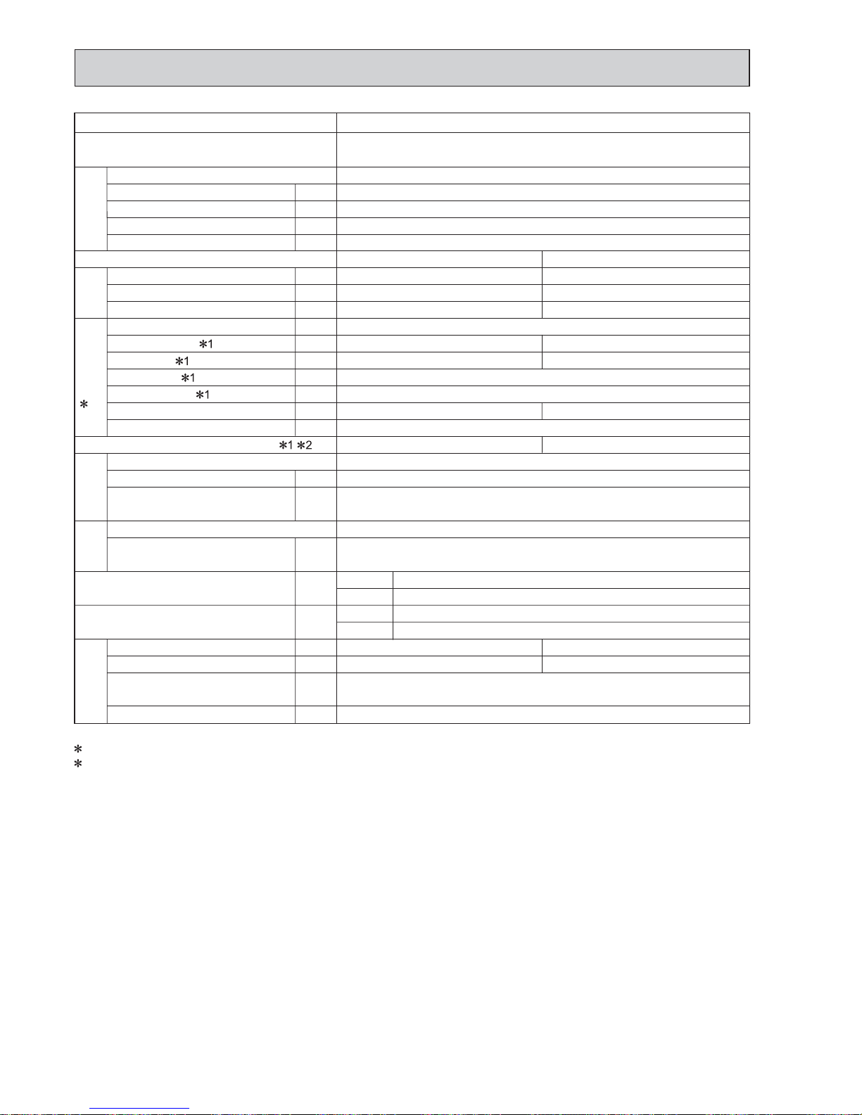
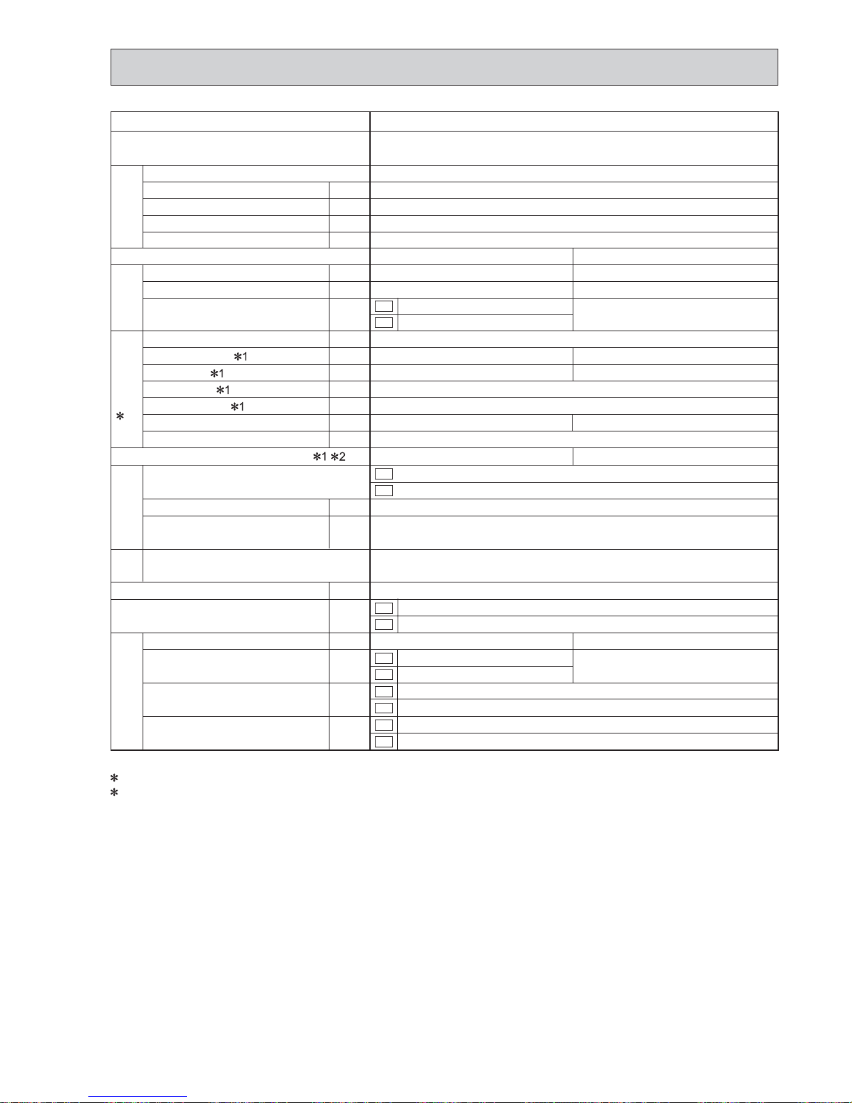
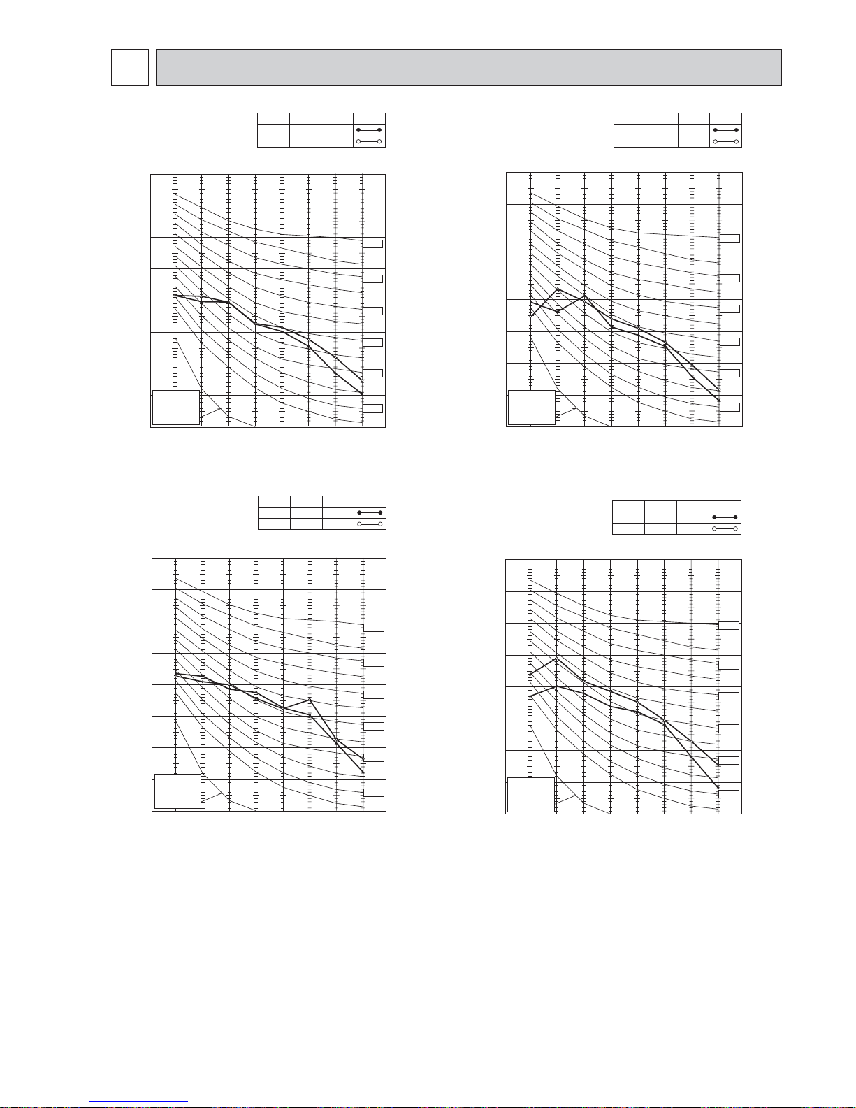
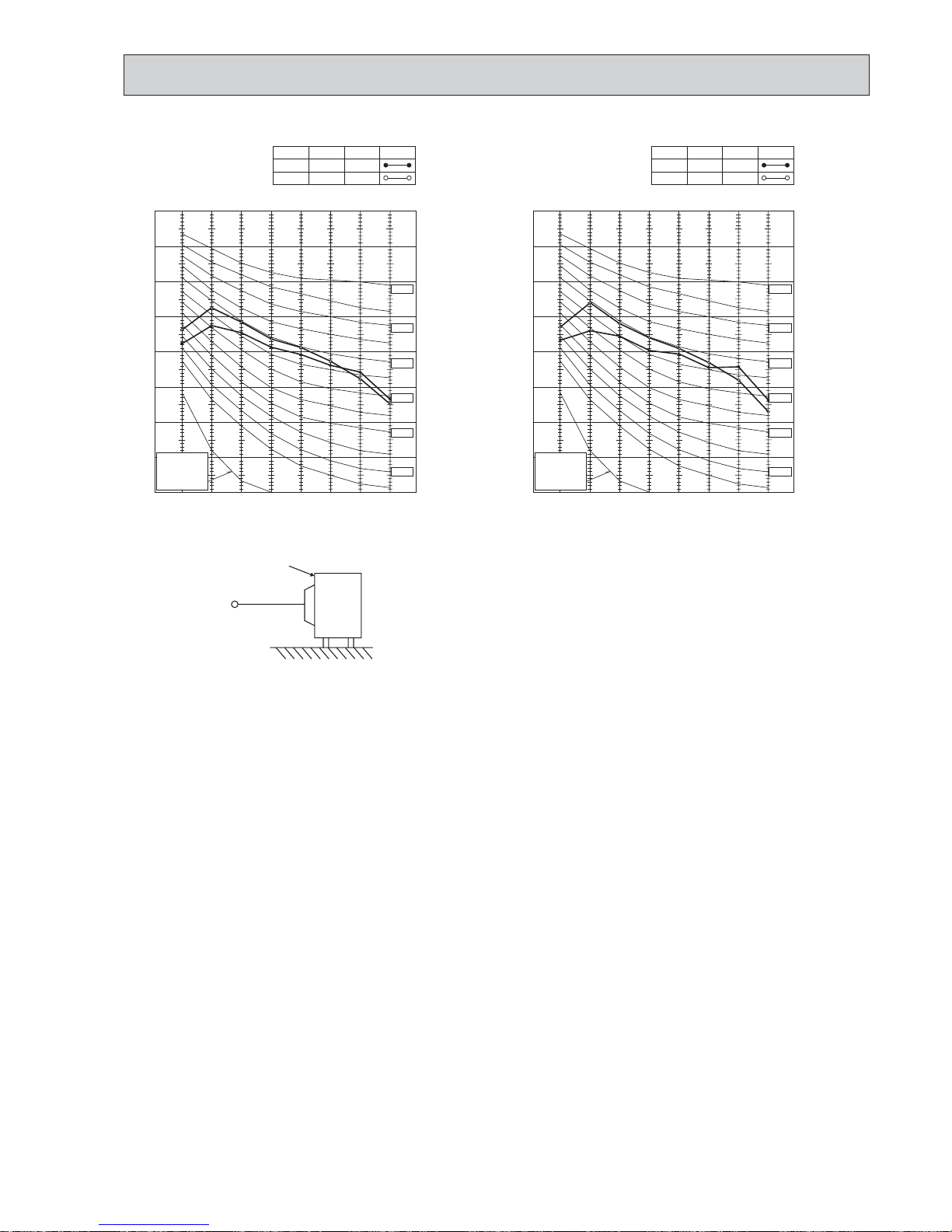
NOISE CRITERIA CURVES
4
90
80
70
60
50
40
30
20
10
63 125 250 500 1000 2000 4000 8000
APPROXIMATE
THRESHOLD OF
HEARING FOR
CONTINUOUS
NOISE
NC-60
NC-50
NC-40
NC-30
NC-20
NC-70
OCTAVE BAND SOUND PRESSURE LEVEL, 0dB = 0.0002 MICRO BAR
BAND CENTER FREQUENCIES, Hz
CoolingHigh
FUNCTION
FAN SPEED
HeatingHigh
47
SPL(dB(A))51LINE
MXZ-3C54VA
MXZ-2C30VA
MXZ-2C52VA
MXZ-2C40VA
90
80
70
60
50
40
30
20
10
63 125 250 500 1000 2000 4000 8000
APPROXIMATE
THRESHOLD OF
HEARING FOR
CONTINUOUS
NOISE
NC-60
NC-50
NC-40
NC-30
NC-20
NC-70
OCTAVE BAND SOUND PRESSURE LEVEL, 0dB = 0.0002 MICRO BAR
BAND CENTER FREQUENCIES, Hz
CoolingHigh
FUNCTION
FAN SPEED
HeatingHigh
47
SPL(dB(A))48LINE
90
80
70
60
50
40
30
20
10
63 125 250 500 1000 2000 4000 8000
NC-60
NC-50
NC-40
NC-30
NC-20
NC-70
OCTAVE BAND SOUND PRESSURE LEVEL, 0dB = 0.0002 MICRO BAR
BAND CENTER FREQUENCIES, Hz
APPROXIMATE
THRESHOLD OF
HEARING FOR
CONTINUOUS
NOISE
CoolingHigh
FUNCTION
FAN SPEED
HeatingHigh
49
SPL(dB(A))50LINE
90
80
70
60
50
40
30
20
10
63 125 250 500 1000 2000 4000 8000
NC-60
NC-50
NC-40
NC-30
NC-20
NC-70
OCTAVE BAND SOUND PRESSURE LEVEL, 0dB = 0.0002 MICRO BAR
BAND CENTER FREQUENCIES, Hz
CoolingHigh
FUNCTION
FAN SPEED
HeatingHigh
46
SPL(dB(A))47LINE
APPROXIMATE
THRESHOLD OF
HEARING FOR
CONTINUOUS
NOISE
OBH584G
16
90
80
70
60
50
40
30
20
10
63 125 250 500 1000 2000 4000 8000
APPROXIMATE
THRESHOLD OF
HEARING FOR
CONTINUOUS
NOISE
NC-60
NC-50
NC-40
NC-30
NC-20
NC-70
OCTAVE BAND SOUND PRESSURE LEVEL, 0dB = 0.0002 MICRO BAR
BAND CENTER FREQUENCIES, Hz
CoolingHigh
FUNCTION
FAN SPEED
HeatingHigh
51
SPL(dB(A))54LINE
MXZ-5C100VA
MXZ-5C100VA2
90
80
70
60
50
40
30
20
10
63 125 250 500 1000 2000 4000 8000
APPROXIMATE
THRESHOLD OF
HEARING FOR
CONTINUOUS
NOISE
NC-60
NC-50
NC-40
NC-30
NC-20
NC-70
OCTAVE BAND SOUND PRESSURE LEVEL, 0dB = 0.0002 MICRO BAR
BAND CENTER FREQUENCIES, Hz
CoolingHigh
FUNCTION
FAN SPEED
HeatingHigh
46
SPL(dB(A))48LINE
MXZ-4C80VA
MXZ-4C80VA2
90
80
70
60
50
40
30
20
10
63 125 250 500 1000 2000 4000 8000
APPROXIMATE
THRESHOLD OF
HEARING FOR
CONTINUOUS
NOISE
NC-60
NC-50
NC-40
NC-30
NC-20
NC-70
OCTAVE BAND SOUND PRESSURE LEVEL, 0dB = 0.0002 MICRO BAR
BAND CENTER FREQUENCIES, Hz
CoolingHigh
FUNCTION
FAN SPEED
HeatingHigh
48
SPL(dB(A))52LINE
MXZ-3C68VA
90
80
70
60
50
40
30
20
10
63 125 250 500 1000 2000 4000 8000
APPROXIMATE
THRESHOLD OF
HEARING FOR
CONTINUOUS
NOISE
NC-60
NC-50
NC-40
NC-30
NC-20
NC-70
OCTAVE BAND SOUND PRESSURE LEVEL, 0dB = 0.0002 MICRO BAR
BAND CENTER FREQUENCIES, Hz
CoolingHigh
FUNCTION
FAN SPEED
HeatingHigh
48
SPL(dB(A))52LINE
MXZ-4C71VA
OBH584G
17
OUTDOOR UNIT
MICROPHONE
1m
Test conditions
Cooling :Dry-bulb temperature 35°C Wet-bulb temperature 24°C
Heating :Dry-bulb temperature 7°C Wet-bulb temperature 6°C
MXZ-6C120VA
90
80
70
60
50
40
30
20
10
63 125 250 500 1000 2000 4000 8000
APPROXIMATE
THRESHOLD OF
HEARING FOR
CONTINUOUS
NOISE
NC-60
NC-50
NC-40
NC-30
NC-20
NC-70
OCTAVE BAND SOUND PRESSURE LEVEL, 0dB = 0.0002 MICRO BAR
BAND CENTER FREQUENCIES, Hz
CoolingHigh
FUNCTION
FAN SPEED
HeatingHigh
55
SPL(dB(A))57LINE
MXZ-6C122VA
90
80
70
60
50
40
30
20
10
63 125 250 500 1000 2000 4000 8000
APPROXIMATE
THRESHOLD OF
HEARING FOR
CONTINUOUS
NOISE
NC-60
NC-50
NC-40
NC-30
NC-20
NC-70
OCTAVE BAND SOUND PRESSURE LEVEL, 0dB = 0.0002 MICRO BAR
BAND CENTER FREQUENCIES, Hz
CoolingHigh
FUNCTION
FAN SPEED
HeatingHigh
55
SPL(dB(A))57LINE
OBH584G
18
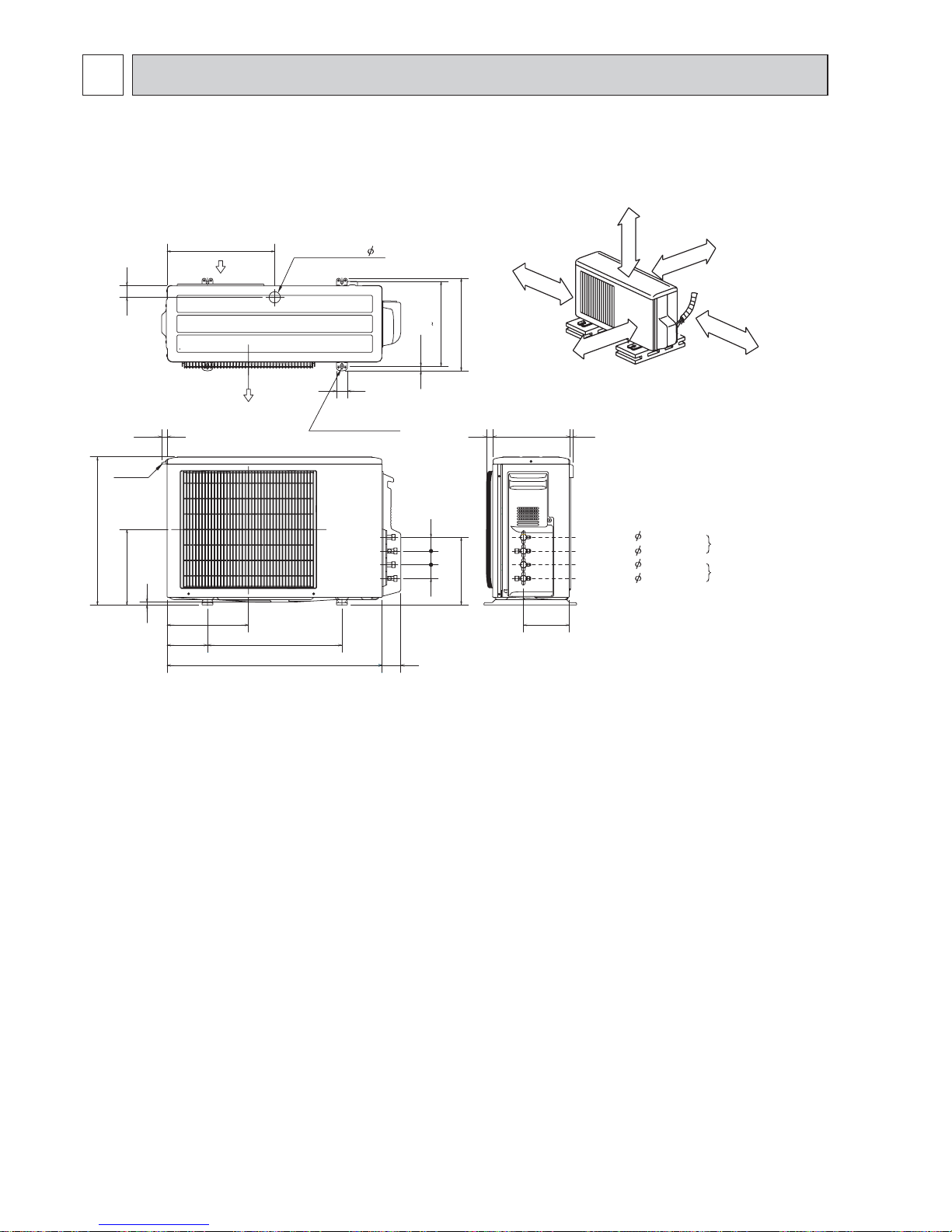
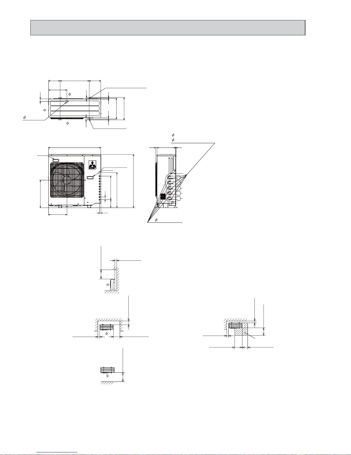
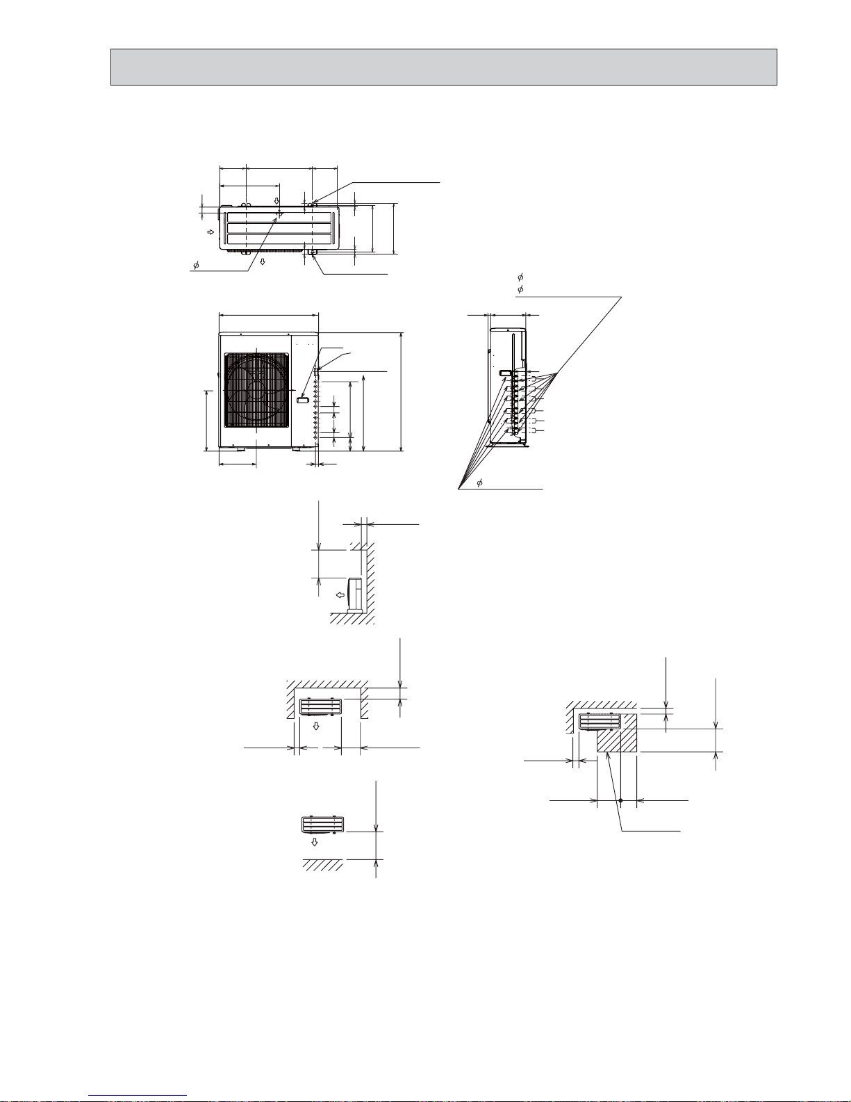
OUTLINES AND DIMENSIONS
5
MXZ-2C30VA MXZ-2C40VA
MXZ-2C52VA
51 51
170.4
44
400
304 325
344.5
17.5
40
22.3
550
280
10
800
500150
302.5
1323 285
51
251.1
69
handle
Air out
2-10x21 Oval hole
Drainage hole 42
Liquid pipe : 6.35(flared)1/4
Gas pipe : 9.52(flared)3/8
Liquid pipe : 6.35(flared)1/4
Gas pipe : 9.52(flared)3/8
B unit
connection
A unit
connection
REQUIRED SPACE
Basically open 100mm or more
without any obstruction in front
and on both sides of the unit.
350mm or more
200mm or more
100mm or more
100mm or more
Open two sides of left,
right, or rear side.
Unit: mm
OBH584G
19
100 or more
500 or more
350 or more350 or more
100 or more
500 or more
100 or more
100 or more
350 or more
200 or more
500 or more
Service space
1.Installation space
Note : Leave front and both sides
free of obstruction.
Note : Leave front and overhead
free of obstruction.
Note : Leave rear, overhead and
both sides free of obstruction.
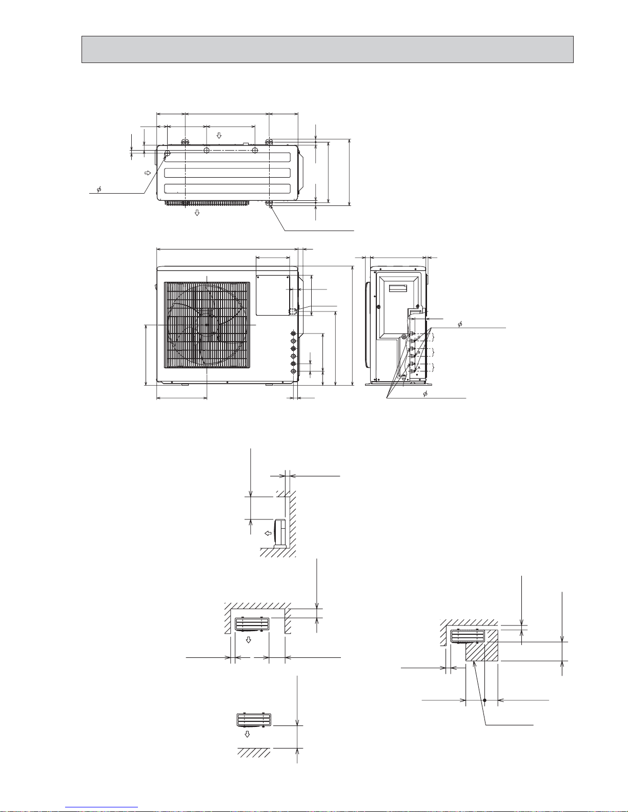
2.Service space
(Bolt Pitch)
4-10 x 21 Oval hole
(Base bolt M10)
Air in
Air in
Air out
3- 33 Drain hole
31.3
12.3 18.3
171500169
63.2
360.6
16.8
288233.1
17.717.7
396
30 330
66.3
840
30
710
299
360
240
200
Indoor and outdoor
connect wiring
39 x 27 hole
27.1
23.1
45
225
84
440
Gas pipe 9.52(flared)3/8
Liquid pipe 6.35(flared)1/4
C unit connection
B unit connection
A unit connection
13
MXZ-3C54VA MXZ-3C68VA
Unit: mm
OBH584G
20
100 or more
500 or more
350 or more350 or more
100 or more
500 or more
100 or more
100 or more
350 or more
200 or more
500 or more
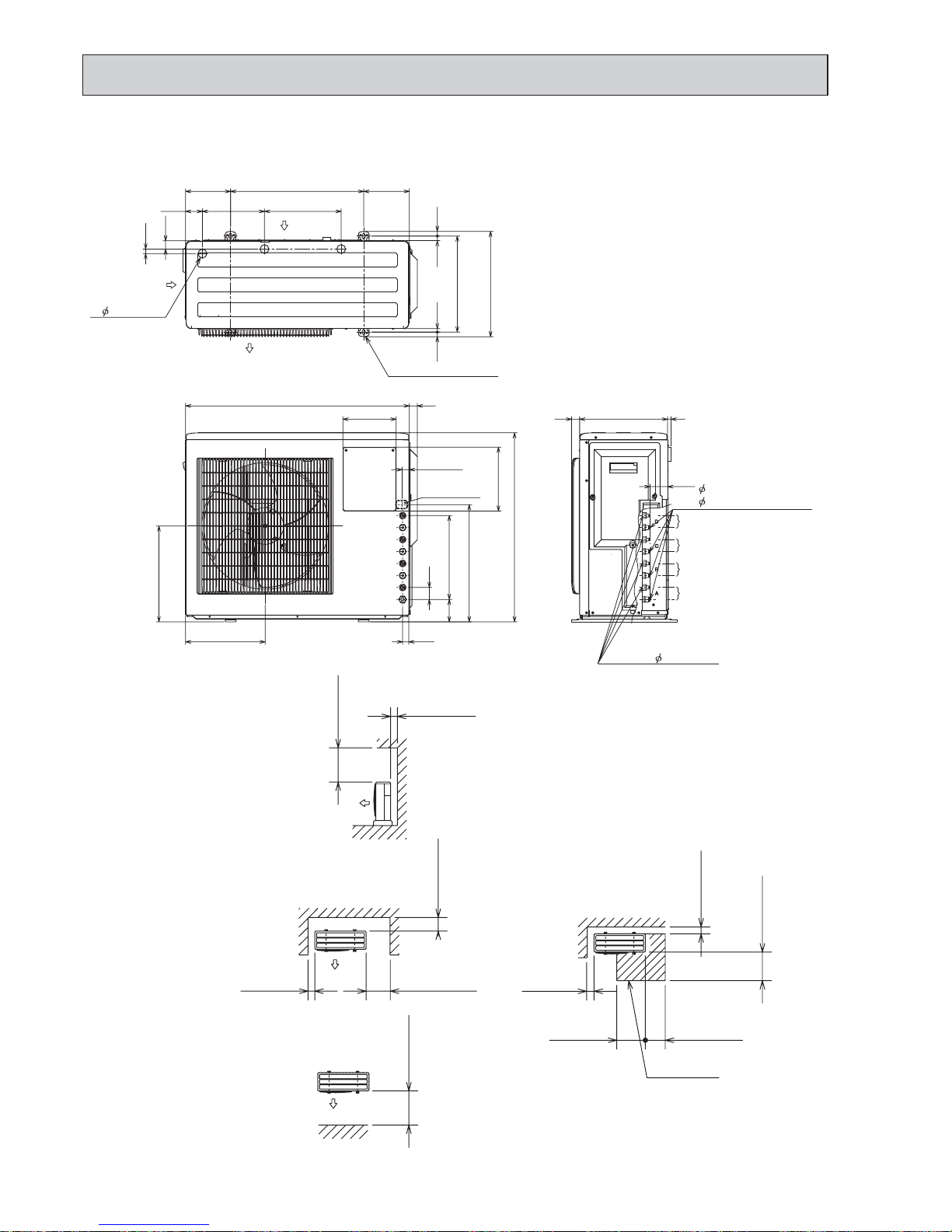
Service space
1.Installation space
Note : Leave front and both sides
free of obstruction.
Note : Leave front and overhead
free of obstruction.
Note : Leave rear, overhead and
both sides
free of obstruction.
2.Service space
Air in
Air in
Air out
(Base bolt M10)
4-10 x 21 Oval hole
3- 33 Drain hole
(Bolt Pitch)
171500
360.6
18.312.3
16.8
31.3
63.2 288233.1
169
396
17.7
17.7
9.52(flared)3/8(B,C,D unit)
Liquid pipe 6.35(flared)1/4
330 1330
66.3
Indoor and outdoor
connect wiring
39 x 27 hole
27.1
23.1
440
45
31584
299
360
710
840 30
200
240
D unit connection
C unit connection
B unit connection
A unit connection
12.7(flared)1/2(A unit)
Gas pipe
MXZ-4C71VA
Unit: mm
OBH584G

21
MXZ-4C80VA
MXZ-5C100VA
Unit: mm
460
317
900
Air out
900
Handle
Handle
35
74
200 200500
35
250
270
355
(Bolt pitch)
387
40
27
16
16
11
24
3- 33 Drain hole
(Base bolt M10)
(Base bolt M10)
2-U Shaped notched hole
2-12 x 36 Oval hole
Air in
Air in
B
A
100 or more
500 or more
350 or more350 or more
100 or more
500 or more
100 or more
100 or more
350 or more
200 or more
500 or more
Service space
32030 10
88
Gas pipe
12.7(flared) 1/2 (A unit)
9.52(flared) 3/8 (B,C,D,E (MXZ-5C100VA) unit)
6.35(flared)1/4
Liquid pipe
D unit connection
E unit connection (MXZ-5C100VA)
C unit connection
B unit connection
A unit connection
1.Installation space
Note : Leave front and both sides
free of obstruction.
Note : Leave front and overhead
free of obstruction.
Note : Leave rear, overhead and
both sides free of obstruction.
2.Service space
23
597
132 405
45
Indoor and
outdoor
connect
wiring
(35 x 53) hole
OBH584G
22
MXZ-4C80VA2
MXZ-5C100VA2
Unit: mm
23
612
147
405
45
Indoor and
outdoor
connect wiring
(35 x 53) hole
Gas pipe
12.7(flared) 1/2 (A unit)
9.52(flared) 3/8 (B,C,D,E (MXZ-5C100VA2) unit)
6.35(flared)1/4
Liquid pipe
D unit connection
E unit connection (MXZ-5C100VA2)
C unit connection
B unit connection
A unit connection
1.Installation space
Note : Leave front and both sides
free of obstruction.
Note : Leave rear, overhead and
both sides free of obstruction.
Air out
42
200 200500
315
355
(Bolt pitch)
387
40
27
16
16
11
24
42 Drain hole
(Fondation bolt M10)
(Fondation bolt M10)
2-U Shaped notched hole
2-12 x 36 Oval hole
Air in
Air in
32025 10
88
475
317
900
Handle
Handle
915
500 or more
100 or more
Note : Leave front and overhead
free of obstruction.
100 or more
350 or more
200 or more
500 or more
2.Service space
100 or more
500 or more
350 or more
350 or more
100 or more
Service space
OBH584G
23
MXZ-6C120VA MXZ-6C122VA
Unit: mm
548
340
900
Air out
1070
Handle
48
200 200500
450
355
(Bolt pitch)
40
27
16
16
11
24
42 Drain hole
(Base bolt M10)
(Base bolt M10)
2-U Shaped notched hole
2-12 x 36 Oval hole
Air in
Air in
100 or more
500 or more
350 or more350 or more
100 or more
500 or more
100 or more
100 or more
350 or more
200 or more
500 or more
Service space
320215
70
Gas pipe
12.7(flared) 1/2 (A unit)
9.52(flared) 3/8 (B,C,D,E,F unit)
6.35(flared)1/4
Liquid pipe
D unit connection
E unit connection
C unit connection
B unit connection
A unit connection
1.Installation space
Note : Leave front and both sides
free of obstruction.
Note : Leave front and overhead
free of obstruction.
Note : Leave rear, overhead and
both sides free of obstruction.
2.Service space
34
730
125
515
45 65
Indoor and
outdoor
connect
wiring
(36 x 96) hole
F unit connection
387
OBH584G
24
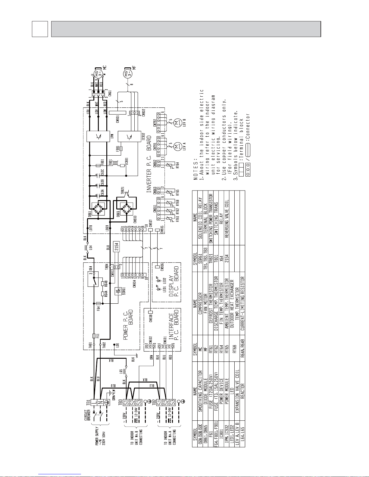
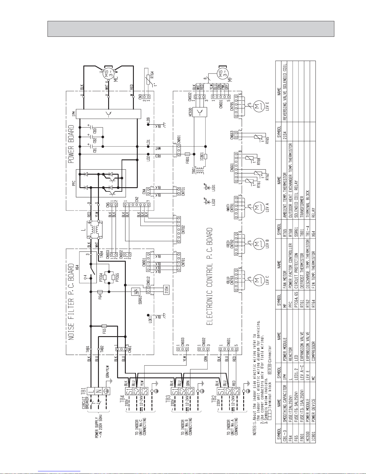
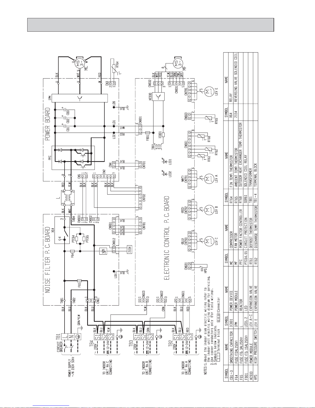
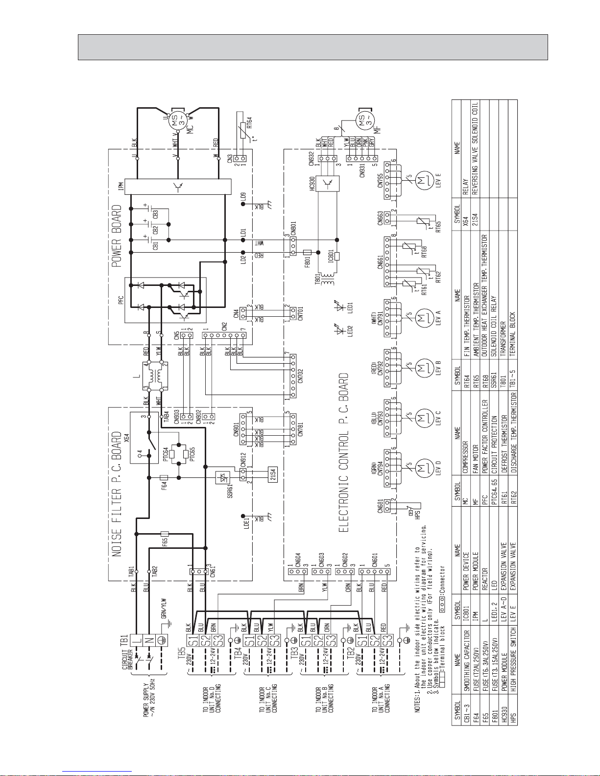
WIRING DIAGRAM
6
MXZ-2C30VA
MXZ-2C40VA
MXZ-2C52VA
OBH584G
25
MXZ-3C54VA
OBH584G
26
MXZ-3C68VA
OBH584G
27
MXZ-4C71VA
OBH584G

28
MXZ-4C80VA
OBH584G
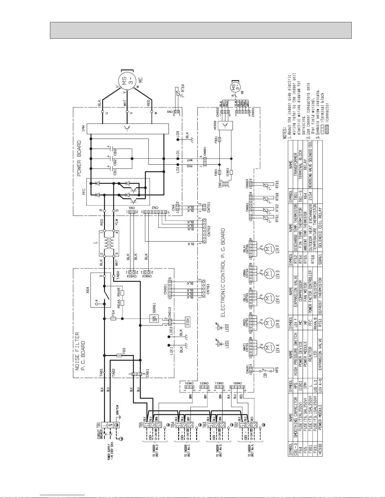
29
MXZ-4C80VA2
OBH584G
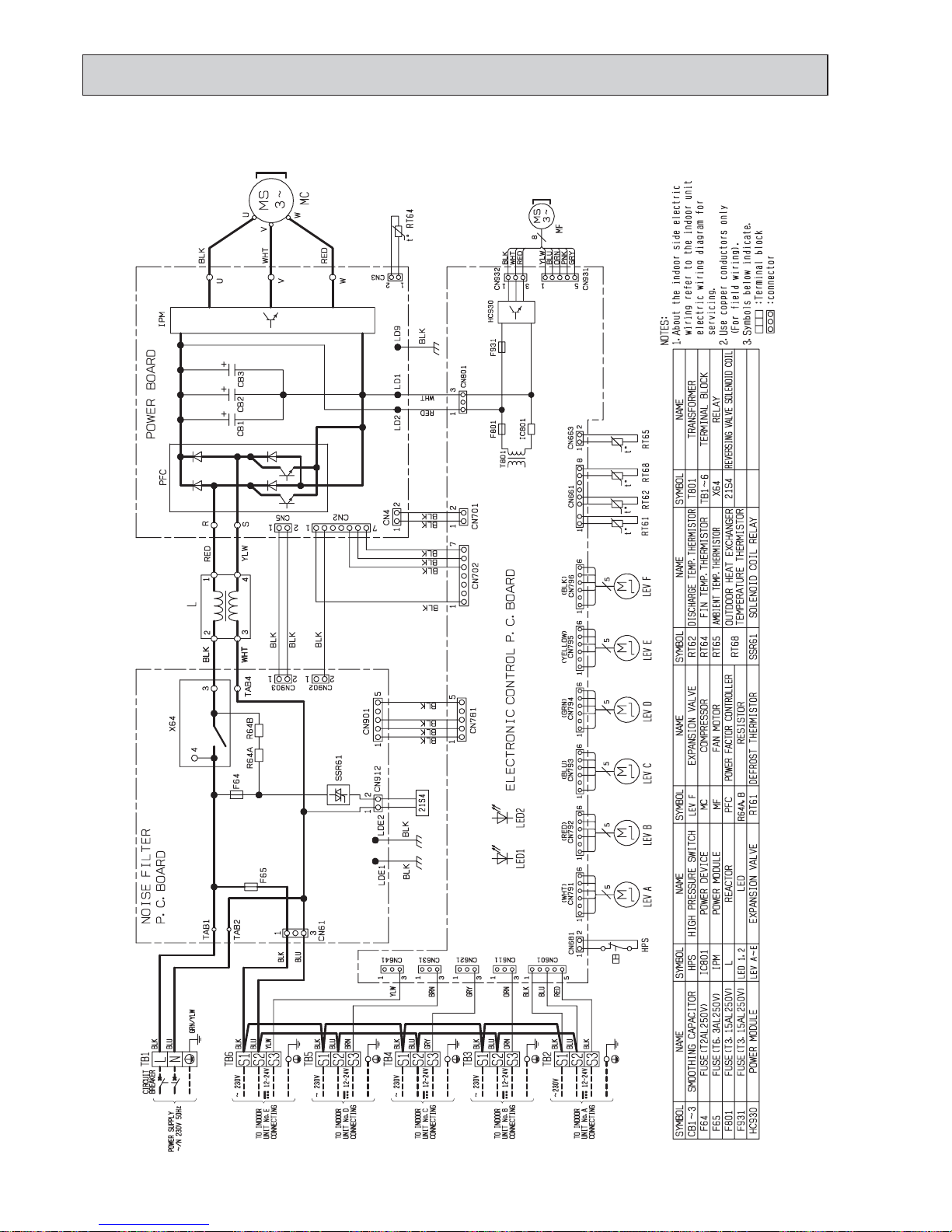
30
MXZ-5C100VA
OBH584G
 Loading...