

Mitsubishi Electronics MXZ-4A80VA User Manual
SPLIT-TYPE AIR CONDITIONER
HFC
utilized
R410A
INSTALLATION MANUAL
CONTENTS
1. THE FOLLOWING SHOULD ALWAYS BE OBSERVED FOR
SAFETY ........................................................................................... 2
2. INSTALLATION DIAGRAM & ACCESSORIES ................................ 2
Model MXZ-4A80VA
3. SELECTING THE INSTALLATION LOCATION ................................ 3
4. OUTDOOR UNIT INSTALLATION ................................................... 4
5. INDOOR/OUTDOOR UNITS CONNECTION FINISHING AND
TEST RUN ....................................................................................... 6
IMPORTANT NOTES
TO COMPLY WITH THE REQUIREMENTS OF AUSTRALIAN
STANDARD AS 3000 S.A.A. WIRING RULES, THE ELECTRICAL
WIRING REQUIRED BETWEEN THE INDOOR AND OUTDOOR
Refer to the installation manual of each indoor unit for indoor unit installation.
FOR INSTALLER
UNITS MUST BE INSTALLED BY A LICENCED ELECTRICAL CON-
TRACTOR.
K
H
F
I
J
E
C
D
1. THE FOLLOWING SHOULD ALWAYS BE OBSERVED FOR
SAFETY
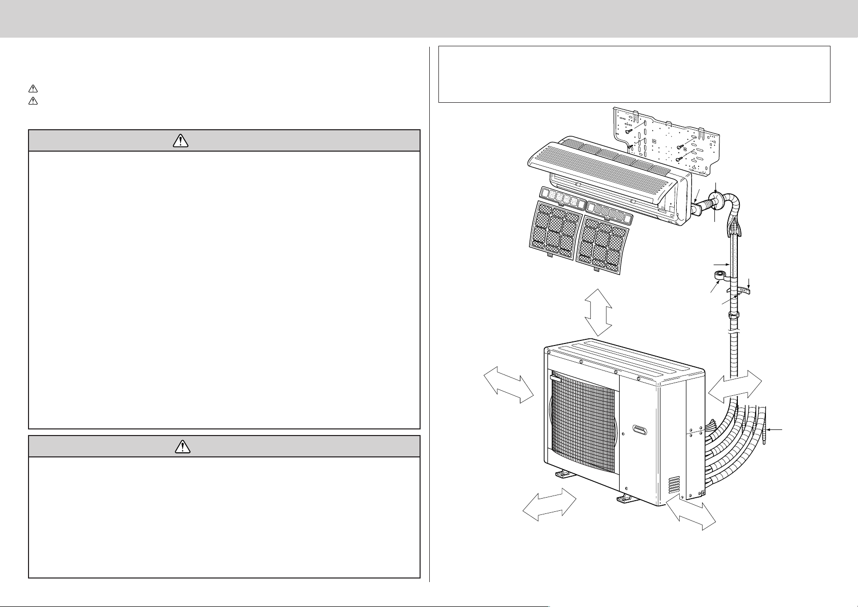
2. INSTALLATION DIAGRAM & ACCESSORIES
• Be sure to read “THE FOLLOWING SHOULD ALWAYS BE OBSERVED FOR SAFETY” before install-
ing the air conditioner.
• Be sure to observe the cautions specified here as they include important items related to safety.
• The indications and meanings are as follows.
WARNING: Could lead to death, serious injury, etc.
CAUTION: Could lead to serious injury in particular environments when operated incorrectly.
• After reading this manual, be sure to keep it together with the OPERATING INSTRUCTIONS in a
handy place on the customer’s site.
WARNING
■ Do not install the unit by yourself (customer).
Incomplete installation could cause injury due to
fire, electric shock, the unit falling or leakage of
water. Consult the dealer from whom you purchased the unit or special installer.
■ Install the unit securely in a place which can
bear the weight of the unit.
When installed in an insufficient strong place, the
unit could fall causing injury.
■ Use the specified wires to connect the indoor
and outdoor units securely and attach the
wires firmly to the terminal block connecting
sections so the stress of the wires is not applied to the sections.
Incomplete connecting and fixing could cause fire.
■ Do not use intermediate connection of the
power cord or the extension cord and do not
connect many devices to one AC outlet.
It could cause a fire or an electric shock due to
defective contact, defective insulation, exceeding the permissible current, etc.
■ Check that the refrigerant gas due not leak
after installation has completed.
If refrigerant gas leaks indoors, and comes into
contact with the fire of a fan heater, space heater,
stove, etc., harmful substances will be generated.
■ Perform the installation securely referring to
the installation manual.
Incomplete installation could cause a personal
injury due to fire, electric shock, the unit falling or
leakage of water.
■ Perform electrical work according to the installation manual and be sure to use an exclusive circuit.
If the capacity of the power circuit is insufficient
or there is insufficient electrical work, it could result in a fire or an electric shock.
■ Attach the electrical cover to the indoor unit
and the service panel to the outdoor unit securely.
If the electrical cover in the indoor unit and/or the
service panel in the outdoor unit are not attached
securely, it could result in a fire or an electric
shock due to dust water, etc.
■ Be sure to use the part provided or specified
parts for the installation work.
The use of defective parts could cause an injury
due to a fire, an electric shock, the unit falling,
leakage of water, etc.
■ Be sure to cut off the main power in case of
setting up the indoor electronic control P.C.
board or wiring works.
It could cause an electric shock.
■ The appliance shall be installed in accordance
with national wiring regulations.
■ When installing or relocating the unit, make
sure that no substance other than the specified refrigerant (R410A) enters the refrigerant
circuit.
Any presence of foreign substance such as air
can cause abnormal pressure rise or an explosion.
Before installation
This installation manual is only for the outdoor unit installation. In installing the indoor units, refer to the
installation manual attached to each indoor unit.
Any structural alternations necessary for the installation must comply with the local building code requirements.
Open as a rule
More than 500 mm
if the front and both
sides are open
More than
100 mm
More than
200 mm if
there are
obstacles to
More than 100 mm
both sides
CAUTION
■ Perform earthing.
Do not connect the earth wire to a gas pipe, water pipe, lightning rod or telephone earth wire.
Defective earthing could cause an electric shock.
■ Do not install the unit in a place where an inflammable gas leaks.
If gas leak and accumulate in the area surrounding the unit, it could cause an explosion.
■ Fasten a flare nut with a torque wrench as
specified in this manual.
When fastened too tight, a flare nut may broken
after a long period and cause a leakage of refrigerant.
■ Install an earth leakage breaker depending on
the installation place (Where it is humid).
If a earth leakage breaker is not installed, it could
cause an electric shock.
■ Perform the drainage/piping work securely
according to the installation manual.
If there is a defect in the drainage/piping work,
water could drop from the unit and household
goods could be wet and damaged.
Open as a rule
More than 500 mm
if the back,
both sides and top
are open
More than 350 mm
Note:
The dimensions given along the arrows above are required to guarantee
the air conditioner’s performance. Install the unit in as wide a place as
possible for later service or repairs.
2
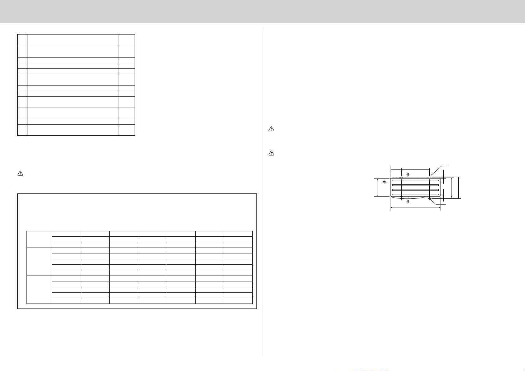
3. SELECTING THE INSTALLATION LOCATION
200
387
355
27
40
500
900
320
Parts to be locally procured
Power supply cord
A
(3-core 2.5 mm
Indoor/outdoor unit connecting wire
B
(4-core 1.0 mm
C
Extension pipe According to “Selecting pipe size”
D Wall hole cover 1
E Piping tape 1
Extension drain hose (or soft vinyl chloride hose of
F
15 mm in internal dia. or hard vinyl chloride pipe VP16)
G Refrigeration oil
H Putty 1
Pipe fixing band
I
(The number depends on the pipe length.)
Fixing screw for I
J
(The number depends on the pipe length.)
K Wall hole sleeve 1
Soft vinyl chloride hose of 25 mm in internal
L
dia. or hard vinyl chloride pipe VP25
2
)
2
/1.5 mm2)
1
1
1
1
Little amount
2 to 7
2 to 7
1
NOTE:
••
• Do not use the drain socket and the drain cap in the cold region.
••
Drain may freeze and it makes the fan stop.
• The “Q’ty” for B to K in the above table is the quantity to be used per indoor unit.
WARNING:
Be sure to use specified accessories and supplied parts for installation work. If there is some deficiency in parts, it may cause a risk of fire, electric shock, injury by a unit fall or water leakage.
Constraints On Indoor Unit Installation
You should note that indoor unit that can be connected to this outdoor unit have the following constraints on
them.
• Indoor units with model numbers 22, 25, 35, 50, 60 and 71 can be connected. Refer to the table below for
possible two-room, three-room and four-room indoor unit combinations.
2 UNIT 25+35 25+50 25+60 25+71 35+35 35+50 35+60
3 UNIT 22+35+71 22+50+50 22+50+60 22+50+71 25+25+25 25+25+35 25+25+50
4 UNIT 22+22+50+50 22+25+25+25 22+25+25+35 22+25+25+50 22+25+25+60 22+25+35+35 22+25+35+50
22+22 22+25 22+35 22+50 22+60 22+71 25+25
35+71 50+50 50+60 50+71 60+60 60+71
22+22+22 22+22+25 22+22+35 22+22+50 22+22+60 22+22+71 22+25+25
22+25+35 22+25+50 22+25+60 22+25+71 22+35+35 22+35+50 22+35+60
25+25+60 25+25+71 25+35+35 25+35+50 25+35+60 25+35+71 25+50+50
25+50+60 35+35+35 35+35+50 35+35+60 35+35+71 35+50+50 35+50+60
22+22+22+22 22+22+22+25 22+22+22+35 22+22+22+50 22+22+22+60 22+22+22+71 22+22+25+25
22+22+25+35 22+22+25+50 22+22+25+60 22+22+25+71 22+22+35+35 22+22+35+50 22+22+35+60
22+25+35+60 22+35+35+35 22+35+35+50 25+25+25+25 25+25+25+35 25+25+25+50 25+25+25+60
25+25+35+35 25+25+35+50 25+35+35+35 35+35+35+35
• Where it is not exposed to strong wind.
• Where airflow is good and dustless.
• Where it is not exposed to rain and direct sunshine.
• Where neighbours are not annoyed by operation sound or hot air.
• Where rigid wall or support is available to prevent the increase of operation sound or vibration.
• Where there is no risk of combustible gas leakage.
• When installing the unit at a high level, be sure to fix the unit legs.
• Where it is at least 3 m away from the antenna of TV set or radio. Operation of the air conditioner may
interfere with radio or TV reception in areas where reception is weak. An amplifier may be required for the
affected device.
• Install the unit horizontally.
• Please install it in an area not affected by snowfall or blowing snow. In areas with heavy snow, please install
a canopy, a pedestal and/or some baffle boards.
Note:
It is advisable to make a piping loop near outdoor unit so as to reduce vibration transmitted from there.
WARNING:
Be sure to install the unit in a place that well sustains its weight.
Installing in a place with less strength may result in a unit falling, causing a risk of injury.
CAUTION:
Avoid the following places for installation where air conditioner trouble is liable to occur.
••
• Where flammable gas could leak.
••
••
• Where there is much machine oil.
••
••
• Salty places such as the seaside.
••
••
• Where sulfide gas is generated such as
••
Air in
2-U-shape notched holes
(Base bolt M10)
a hot spring.
••
• Where there is high-frequency or wire-
••
less equipment.
Air in
Air out
2-12 × 36 Oval holes
(Base bolt M10)
(Unit: mm)
Note:
When operating the air conditioner in low outside temperature, be sure to follow the instructions described below.
••
• Never install the outdoor unit in a place where its air inlet/outlet side may be exposed directly to
••
wind.
••
• To prevent exposure to wind, install the outdoor unit with its air inlet side facing the wall.
••
••
• To prevent exposure to wind, it is recommended to install a baffle board on the air outlet side of the
••
outdoor unit.
3
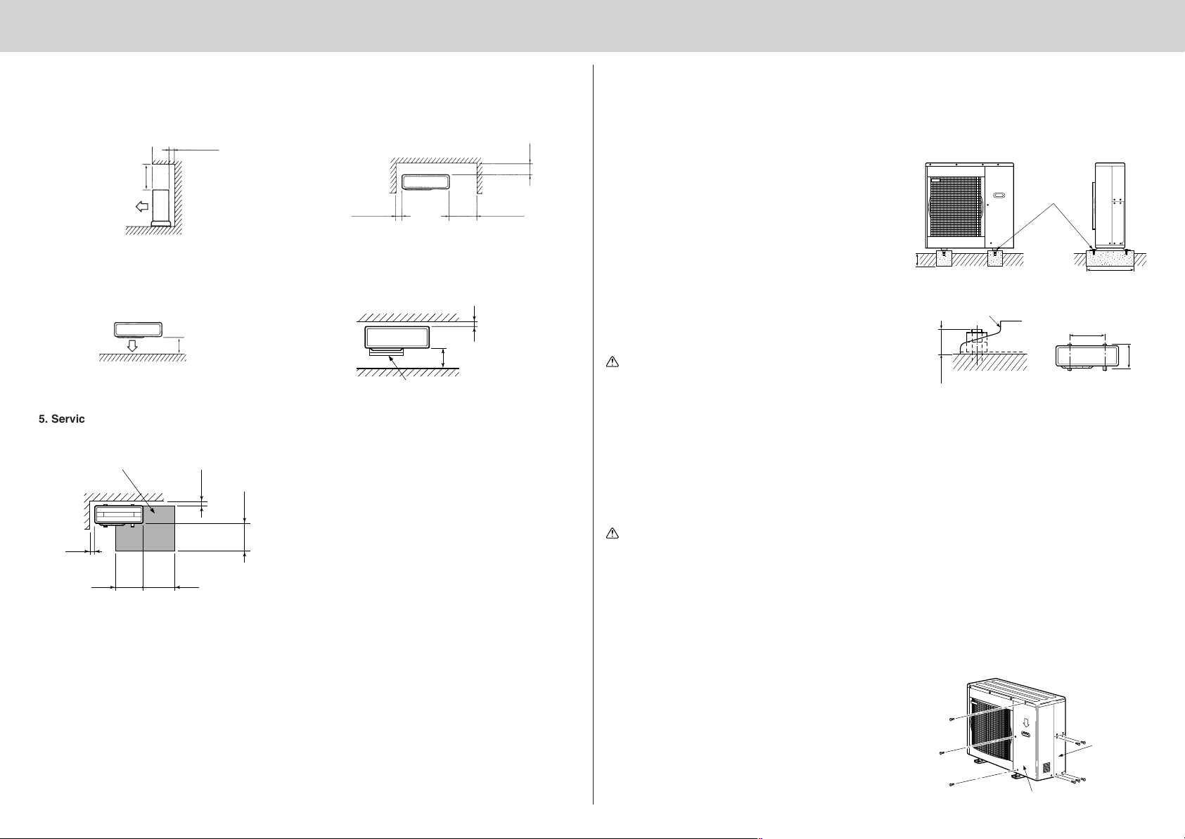
4. OUTDOOR UNIT INSTALLATION
500
330
FREE SPACE REQUIRED AROUND OUTDOOR UNIT (Unit: mm)
1. Top side obstacles
When there is an obstacle behind the rear side only,
it does not matter if there is an obstacle over the
top side as shown in the figure below.
100 or more
500 or more
3. Obstacles on front (blowing) side only
In this case, the rear, both sides and top should be
open.
500 or more
5. Service space
Keep the service space as shown in the figure below for maintenance.
Service space
100 or more
500 or more
100 or more
500 or more
350 or more
Note:
Make sure not to install several outdoor units sideways next to each other.
2. Front (blowing) side open
As long as space like the one shown in the figure
can be maintained, it does not matter if there are
obstacles in three directions (but top side is open).
4. Obstacles on front and rear side only
The unit can be used by attaching an optional outdoor blowing guide (MAC-855SG) (but both sides
and top are open).
Blowing guide (MAC-855SG)
200 or more
500 or more
350 or more100 or more
100 or more
4-1 INSTALLING THE UNIT
• Be sure to fix the unit’s legs with bolts when installing it.
• Be sure to install the unit firmly to ensure that it does not fall by an earthquake or a gust.
• Refer to the figure in the right for concrete foundation.
Note:
The length of anchor bolts should be within 25 mm from
each anchor leg.
Fix here with
M10 bolts.
Make the setting
depth deeper.
Make with wider.
• Do not use the drain socket and the drain cap in the cold
region.
Drain may freeze and it makes the fan stop.
Anchor leg
CAUTION:
Be sure to carry out drain piping work following the installation manual.
If there is some deficiency in draining and piping work, it
may cause a risk of dripping from the unit, wetting or
25 mm or less
Anchor both length
Anchor both pitch
(Unit: mm)
forling your property.
4-2 MOUNTING ARRANGEMENT OF DRAIN SOCKET
Please perform the drain piping work only when draining from one place.
CAUTION:
Do not use drain socket and drain cap in the cold region.
Drain may freeze and it makes the fan stop.
1 Please choose one hole to discharge drain and install the drain socket to the hole.
2 Please close the rest of the holes with the drain caps.
3 Please connect a vinyl hose of 25 mm in the inside diameter on the market with the drain socket and lead drain.
4-3 HOW TO REMOVE THE SERVICE PANEL AND THE CONNECT COVER
• Remove the four service panel securing screws, and pull
the panel down in an arrow direction to remove the service
panel.
• Remove the four connect cover securing screws to remove
the connect cover.
Service panel
4
Connect
cover
 Loading...