

Mitsubishi Electric MSH09TW, MUH09TW, MSH12TN, MUH12TN, MSH15TN Service Manual
...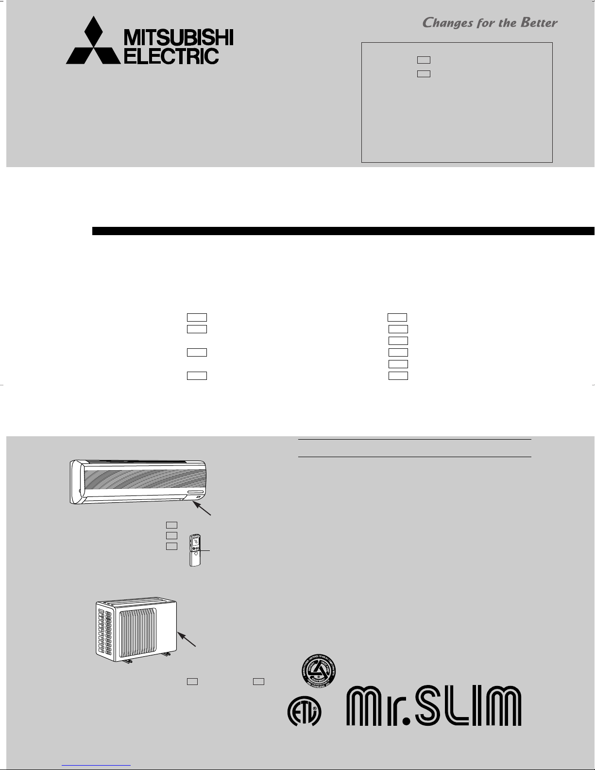
SPLIT-TYPE, HEAT PUMP AIR CONDITIONERS
L
I
S
T
E
D
CUS
SERVICE MANUAL
Wireless type
Models
MSH09TW · MUH09TW
MSH12TN · MUH12TN
MSH15TN · MUH15TN
MSH17TN · MUH17TN
MSH09TW
MSH12TN
MSH15TN
MSH17TN
-
-
-
-
· MUH09TW
· MUH12TN
· MUH12TN
· MUH15TN
· MUH15TN
· MUH17TN
Revision:
● MUH12TN- has been added.
● MUH15TN- has been added.
●REFRIGERANT SYSTEM DIAGRAM of
MXZ30TN and MXZ30TN2 has partly been
changed.
●PARTS LIST of MXZ30TN and MXZ30TN2
has partly been changed
●Please void OB275 Revised edition-C.
U2
U2
No. OB275
REVISED EDITION-D
U1U1
-
U1U1
-
U2
-
U1U1
-
U2
-
U1U1
-
Inverter-controlled multi system Model
Indication of
MSH12TN
MSH15TN
MSH17TN
INDOOR UNIT
MUH15TN
OUTDOOR UNIT
MSH12TN -
MSH15TN -
MSH17TN -
MUH15TN - MUH15TN -
U1
U1
U1
model name
Remote
controller
Indication of
model name
U2U1
· MXZ30TN
· MXZ30TN2
CONTENTS
1. FEATURES·························································2
2. TECHNICAL CHANGES····································5
3. PART NAMES AND FUNCTIONS······················7
4. INDOOR UNIT COMBINATION························10
5. SPECIFICATION···············································11
6. DATA·································································17
7. OUTLINES AND DIMENSIONS·······················39
8. WIRING DIAGRAM ··········································43
9. REFRIGERANT SYSTEM DIAGRAM··············51
10. MICROPROCESSOR CONTROL ····················54
11. SERVICE FUNCTIONS·····································72
12. TROUBLESHOOTING ······································75
13. DISASSEMBLY INSTRUCTIONS···················101
14. PARTS LIST····················································114
15. OPTIONAL PARTS·········································126
The Slim Line.
From Mitsubishi Electric.
TM

1
MSH12TN MSH15TN MSH17TN -
U1
U1
U1
MSH12TN
MSH15TN
MSH17TN
MSH09TW
MSH09TW -
U1
MUH09TW
MUH09TW -
U1
MUH15TN -
U1
MUH15TN -
U2
U1
MUH15TN
MUH17TN -
U1
MUH17TN
MXZ30TN MXZ30TN2
LCD wireless
remote controller
MUH12TN
MUH12TN-
U2
MUH12TN-
USA Remark
MSH09TW
MSH12TN
MSH15TN
MSH17TN
No
40min.
27˚F
38˚F
CANADA
RT63(Outdoor):
for protection in low ambient temperature
Refer to
U1
U1
U1
U1
DIFFERENT POINTS between models for USA and CANADA
AMBIENT
TEMPERATURE
THERMISTOR
INTERVAL
TIME
START
TEMPERATURE
FINISH
TEMPERATURE
DEFROSTING
Have
15min.
32˚F
50˚F
8. WIRING DIAGRAM
10. MICRO PROCESSOR CONTROL
10-1. -HEAT mode of "I FEEL CONTROL"-
5. Outdoor temperature control(P. 60)
10. MICRO PROCESSOR CONTROL
10-1. -HEAT mode of "I FEEL CONTROL"-
3. Defrosting (P.59)
11. SERVICE FUNCTIONS
11-2. CHANGE IN DEFROST SETTING(P.72)
for protection in low ambient temperature
MSH09TW MSH12TN MSH15TN MSH17TN -
Model
FEATURES
2
SWING
Model Cooling capacity Heating capacity SEER HSPF(44/55)
MSH09TW MSH09TW - 8,800Btu/h 10,500Btu/h 10.0 6.8/5.9
MSH12TN MSH12TN - 12,600/12,900Btu/h 13,000/13,500Btu/h 10.2 6.8/5.9
MSH15TN MSH15TN - 14,300/14,600Btu/h 14,500/14,800Btu/h 10.7 6.8/5.9
MSH17TN MSH17TN - 16,000/16,200Btu/h 16,800/17,200Btu/h 10.4 6.8/5.9
U1
U1
U1
U1
“I FEEL CONTROL” IN OUR LCD WIRELESS REMOTE CONTROLLER WITH ON/OFF PROGRAM TIMER
Mitsubishi Electric’s new wireless remote controller incorporates a number of advanced features that provide even greater con-
trol and ease-to-use. It has a liquid crystal display which indicates such information as mode, fan speed and temperature
selected as well as the programmed ON/OFF timer. It is also equipped with “I Feel Control”, a unique Mitsubishi Electric feature that allows the user to adjust the temperature to exactly the level he or she wants simply by tapping the button that
describes present conditions : “Too Cool” or “Too Warm”. The optimum temperature set this way is then memorized for immediate recall whenever the air conditioner is used again.
Select desired air flow direction.
REMOTE-CONTROL OPERATION MODE
Using the remote controller, you can select from five airflow settings to match room layout and the location of people. Also, you
can set the vane to swing automatically.
AUTO-RESTART FUNCTION
The auto-restart function restarts the equipment when power is
restored following an outage automatically. Operation resumes in
the mode in which the equipment was running immediately before
the outage.
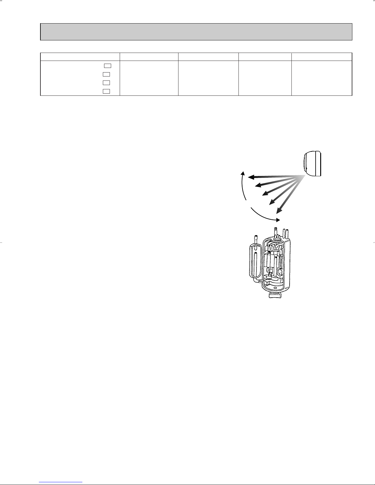
HIGH PERFORMANCE ROTARY COMPRESSOR
The advanced design of Mitsubishi Electric’s powerful and energy
efficient rotary compressor results in lower operating costs and
longer service life.
3
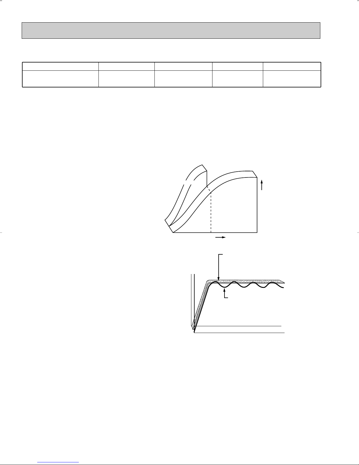
Time
Set Temperature
Conventional
model
Inverter model
MXZ30TN MXZ30TN2
Time
Set Temperature
Conventional Model:
Temperature are
adjusted by switching the
compressor off and on.
Inverter Model:
Uniform temperatures are
maintained by finely tuned
control of compressor speed.
Optimum Comfort in Any Situation
Model Cooling capacity Heating capacity SEER HSPF(44)
MXZ30TN MXZ30TN2
28,400Btu/h
(4,160 - 30,500)
28,600Btu/h
(5,790 - 38,000)
11.0 7.5
Inverter Technology
Outdoor unit uses inverter compressor technology (Variable Frequency Drive) to provide exceptional indoor high-speed
cooling and heating.
By responding to indoor temperature changes, the system reduces power consumption by varying the compressor speed for
extra energy savings and performs only to the levels needed to maintain a constant and comfortable indoor environment.
Extra Energy Savings
For optimum performance inverter technology controls the electrical current to the compressor, delivering only the energy
needed to match the cooling and heat load of a room. This feature reduces energy consumption.
High-Speed Heating and Cooling
Compressor rotation is controlled to maximize
efficiency, changing speeds according to the cooling
and heating load of a room. This application means
the desired temperature is reached much faster.
Optimum Comfort Year-Round
Unlike conventional units that start and stop repetitively,
inverter units are able to detect subtle changes in room
temperature and adjust airflow automatically. This adaptation
means less temperature variation and more comfortable rooms.
4

2
TECHNICAL CHANGES
MSH09NW2 ➔ MSH09TW
1. Indoor unit has changed.
2. Remote controller has changed.
MSH12NN2 ➔ MSH12TN
1. Remote controller has changed.
2. Union size of connect pipe for gas has changed.
MSH15NN2 ➔ MSH15TN
MSH17NN2 ➔ MSH17TN
1. Remote controller has changed.
MUH09NW2 ➔ MUH09TW
1. Outdoor unit has changed.
MUH12NN2 ➔ MUH12TN
1. Outdoor unit has changed.
MUH15NN2 ➔ MUH15TN
1. Only model name has changed.
MUH17NN2 ➔ MUH17TN
1. Valve type has changed (Size for connecting pipe is the same).
MSH09NW2 - ➔ MSH09TW -
1. Indoor unit has changed.
2. Remote controller has changed.
MSH12NN2 - ➔ MSH12TN -
1. Remote controller has changed.
2. Union size of connect pipe for gas has changed.
MSH15NN2 - ➔ MSH15TN MSH17NN2 - ➔ MSH17TN -
1. Remote controller has changed.
MUH09NW2 - ➔ MUH09TW -
1. Outdoor unit has changed.
MUH12NN2 - ➔ MUH12TN -
1. Outdoor unit has changed.
MUH15NN2 - ➔ MUH15TN -
1. Only model name has changed.
U1U1
U1U1
U1U1
U1U1
U1U1
U1U1
U1U1
MUH17NN2 - ➔ MUH17TN -
1. Valve type has changed (Size for connecting pipe is the same).
MXZ30TN
1. New model.
U1U1
5

MXZ30TN ➔ MXZ30TN2
1. Noise filter P.C. board has changed to improve the capacity for protecting the inverter-controlled circuit when the
voltage higher than the rated one is aupplied with the inverter-controlled circuit.
2. Noise filter P.C. board for “MXZ30TN” and “MXZ30TN2” are not interchangeable.
3. Service parts have been changed as follows according to above change;
•The value of R(resistor)has changed. 10Ω ➔ 20Ω
•TB5(terminal block) has been removed.
MUH12TN - ➔ MUH12TN MUH15TN - ➔ MUH15TN -
U2U1
U2U1
1. Outdoor haet exchanger has changed.
Outdoor haet exchanger for “TN - ” and “TN - ” are not interchangeable.
U2U1
6
3
Installation plate
Installation plate fixing screw 4 x 25 mm(0.16 x 0.98 in.)
Remote controller mounting hardware
Fixing screw for 3 3.5 x 16 mm(0.14 x 0.63 in.) (Black)
Battery (AAA) for remote controller
Wireless remote controller
Felt tape (Used for left or left-rear piping)
1
5
1
2
2
1
1
1
2
3
4
5
6
7
MSH12TN
MSH15TN
MSH17TN
MSH09TW MSH09TW -
U1
1
6
1
2
2
1
1
MSH12TN
-
MSH15TN
-
MSH17TN
-
U1
U1
U1
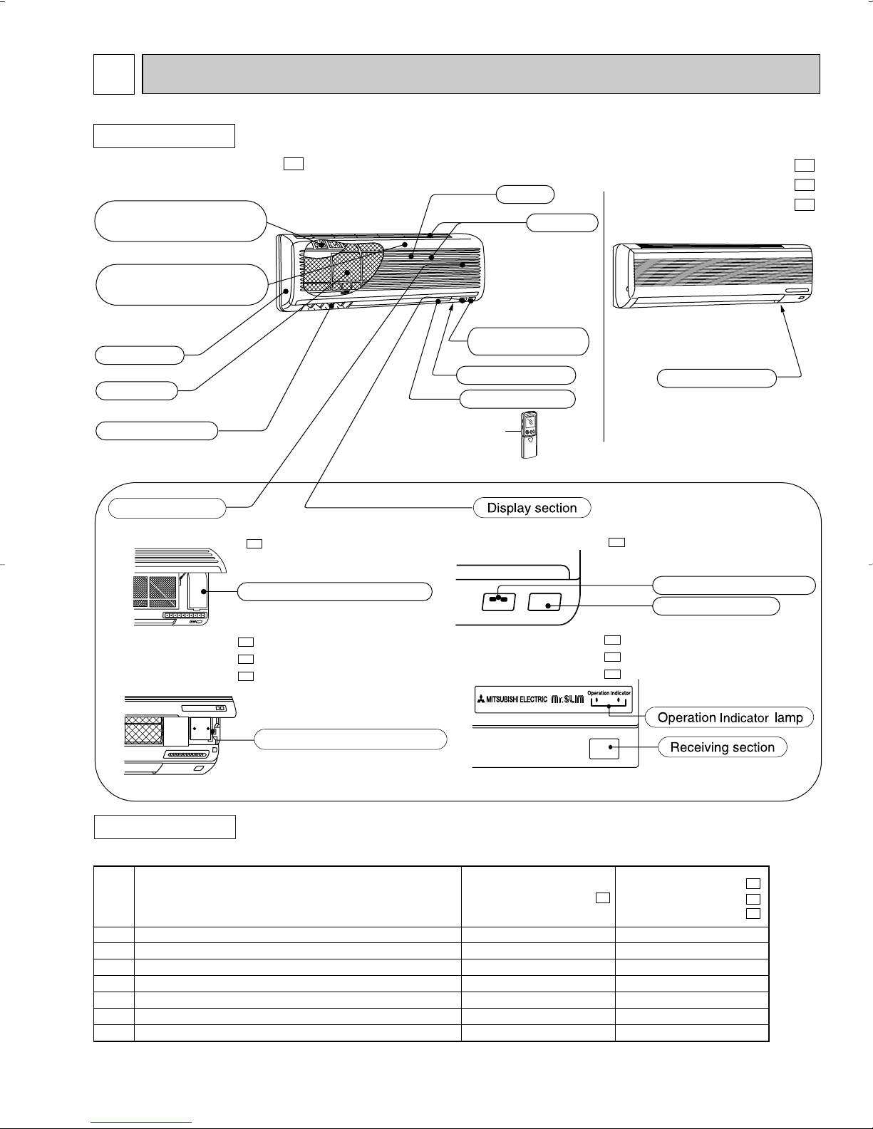
PART NAMES AND FUNCTIONS
INDOOR UNIT
MSH09TW MSH09TW -
Deodorizing filter(option)
(gray sponge type)
Air cleaning filter(option)
(white bellows type)
Front panel
Air filter
Vertical vanes
Operation section
(When the grille is opened)
MSH09TW MSH09TW -
U1
U1
Grille
MSH12TN
MSH15TN
MSH17TN
MSH12TN MSH15TN MSH17TN -
U1
U1
U1
Air inlet
Remote control
receiving section
Model indication
Model indication
Horizontal vane
Remote controller
MSH09TW MSH09TW -
U1
Emergency operation switch
MSH12TN MSH12TN MSH15TN MSH15TN MSH17TN MSH17TN -
U1
U1
U1
Emergency operation switch
ACCESSORIES
MSH12TN MSH12TN MSH15TN MSH15TN MSH17TN MSH17TN -
7
U1
U1
U1
Operation indicator lamp
Receiving section
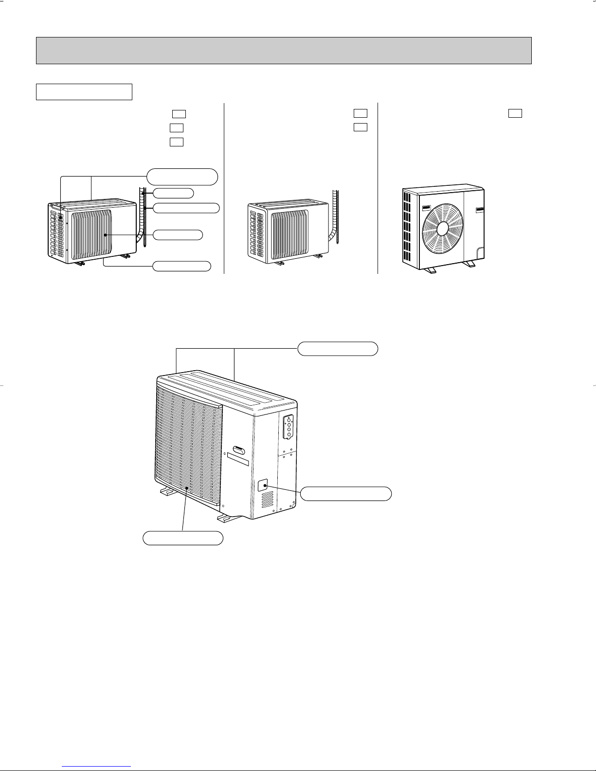
Air inlet
Piping
Drain hose
Air outlet
Drain outlet
(back and side)
OUTDOOR UNIT
Air inlet
Air outlet
(back and side)
Model indication
MUH09TW MUH09TW MUH12TN MUH12TN -
MUH12TN -
MXZ30TN MXZ30TN2
U1
U1
U2
MUH15TN
MUH15TN MUH15TN -
U1
MUH17TN MUH17TN -
U2
U1
8
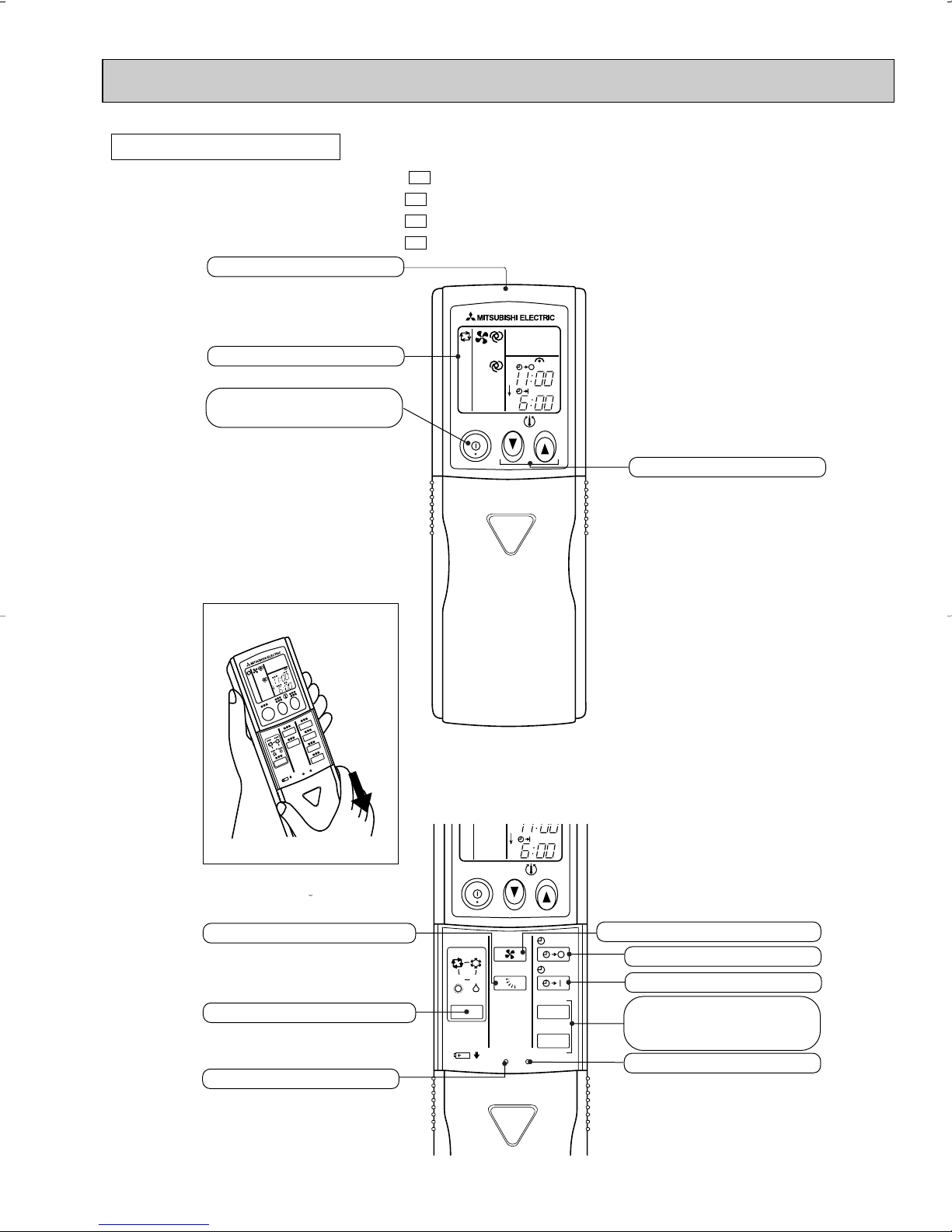
REMOTE CONTROLLER
ON/OFF
TOO
COOL
PM
AM
TOO
WARM
ON/OFF
FAN
TOO
WARM
TOO
COOL
VANE
MODE
STOP
START
HR.
MIN.
I FEEL
COOL
HEAT
DRY
PM
CLOCK
AM
RESET CLOCK
Open the front lid.
Signal transmitting section
Operation display section
OPERATE /STOP
(ON /OFF)button
TEMPERATURE buttons
OPERATION SELECT button
FAN SPEED CONTROL button
OFF-TIMER button
HR. button
MIN. button
(TIME SET button)
ON-TIMER button
RESET button
VANE CONTROL button
CLOCK SET button
MSH09TW
MSH12TN
MSH15TN
MSH17TN
MSH09TW MSH12TN MSH15TN MSH17TN -
U1
U1
U1
U1
9
4
09
12
15
17
09+09
09+12
09+15
09+17
12+12
09+09+09
09+09+12
90
90
90
90
90
90
90
90
90
90
90
4.0
4.9
4.9
8.6
8.6
8.9
8.9
10.5
10.6
13.6
14.9
4.5
5.4
5.4
9.5
9.5
9.9
9.9
11.6
11.7
15.1
16.4
–
–
–
–
–
–
–
–
–
8,800
13,660
8,800
(4,160~9,210)
12,900
(5,600~15,350)
14,600
(5,600~17,010)
16,200
(6,470~18,720)
17,600
(5,470~18,680)
21,700
(6,240~22,760)
23,400
(6,240~24,030)
25,000
(6,220~27,170)
25,800
(6,300~27,900)
26,400
(9,740~29,150)
28,400
(9,940~30,500)
1,030
(510~1,280)
1,250
(510~1,680)
1,250
(510~1,780)
2,200
(500~2,620)
2,200
(550~3,230)
2,280
(540~3,270)
2,280
(540~3,430)
2,680
(550~4,000)
2,700
(540~4,100)
3,500
(700~4,500)
3,800
(810~4,610)
–
–
–
–
8,800
12,900
14,600
16,200
12,900
8,800
7,370
8,800
12,900
14,600
16,200
8,800
8,800
8,800
8,800
12,900
8,800
7,370
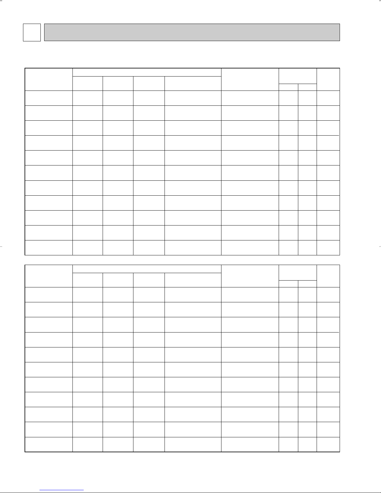
Indoor units
combination
Unit A Unit B Unit C
Cooling capacity (BTU/h)
Total
Outdoor unit
power consumption
(W)
Current
(A)
Power
factor
(%)
208V 230V
NOTE: Electrical data is for outdoor unit only.
MXZ30TN MXZ30TN2
09
12
15
17
09+09
09+12
09+15
09+17
12+12
09+09+09
09+09+12
90
90
90
90
90
90
90
90
90
90
90
4.3
4.7
5.5
6.3
7.6
8.6
9.4
10.6
9.9
10.6
11.0
4.8
5.2
6.1
6.9
8.4
9.6
10.4
11.7
10.9
11.8
12.1
–
–
–
–
–
–
–
–
–
9,530
12,960
10,500
(5,790~16,950)
13,500
(6,420~22,400)
14,800
(6,470~23,180)
17,200
(6,520~23,550)
21,000
(6,520~26,900)
24,000
(6,730~30,000)
25,300
(7,490~32,240)
27,700
(8,140~37,100)
27,000
(7,660~36,890)
28,590
(8,900~37,500)
28,600
(9,040~38,000)
1,100
(560~1,990)
1,200
(560~2,340)
1,400
(570~2,480)
1,600
(600~2,710)
1,950
(620~2,900)
2,210
(640~3,130)
2,400
(640~3,360)
2,700
(690~3,900)
2,520
(650~3,850)
2,720
(710~3,920)
2,800
(710~3,970)
–
–
–
–
10,500
13,500
14,800
17,200
13,500
9,530
7,820
10,500
13,500
14,800
17,200
10,500
10,500
10,500
10,500
13,500
9,530
7,820
Indoor units
combination
Unit A Unit B Unit C
Heating capacity (BTU/h)
Total
Outdoor unit
power consumption
(W)
Current
(A)
Power
factor
(%)
208V 230V
INDOOR UNITS COMBINATION
10
5
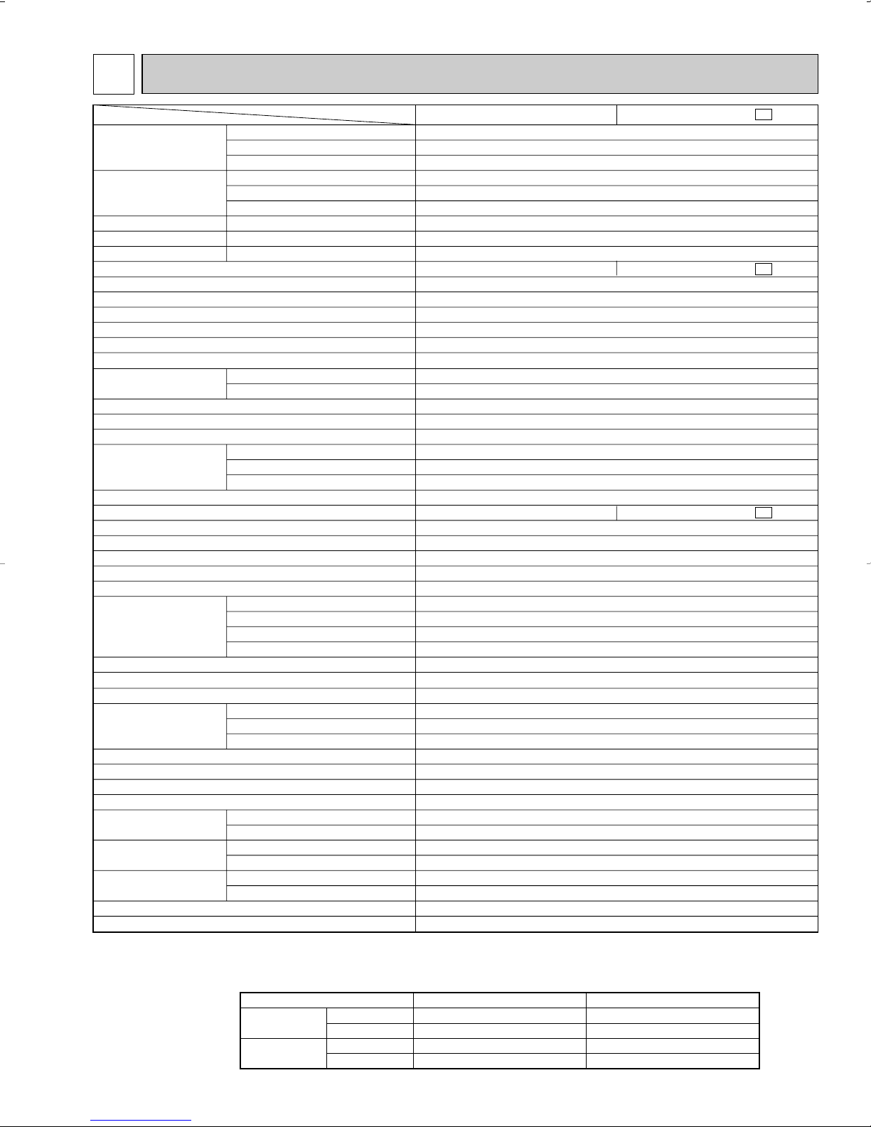
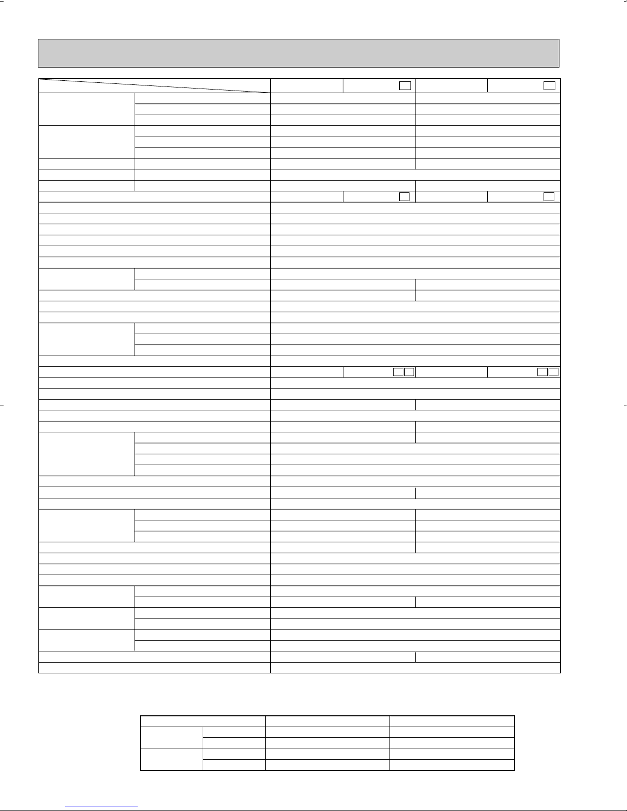
Item
Model
MSH09TW -
Capacity
Power
consumption
EER [SEER]
HSPF IV(V)
COP
INDOOR UNIT MODEL
External finish
Power supply
Max. fuse size (time delay)/ Disconnect switch
Min. circuit ampacity
Fan motor
Auxiliary heater
Airflow Low—Med.—High
Moisture removal
Sound level Low-Med.-High
Cond. drain connection O.D.
Dimensions
Weight
OUTDOOR UNIT MODEL
External finish
Power supply
Max. fuse size (time delay)
Min. circuit ampacity
Fan motor
Compressor
Refrigerant control
Sound level
Defrost method
Dimensions
Weight
REMOTE CONTROLLER
Control voltage (by built-in transformer)
REFRIGERANT PIPING
Pipe size
(Min. wall thickness)
Connection method
Between the indoor
& outdoor units
Refrigerant charge (R22)
Refrigerating oil (Model)
Btu/h
Btu/h
Btu/h
W
W
V, phase, Hz
A
A
F.L.A
A(kW)
CFM
CFM
pt./h
dB(A)
in.
in.
in.
in.
Ib.
V, phase, Hz
A
A
F.L.A
R.L.A
L.R.A
dB(A)
in.
in.
in.
Ib.
in.
in.
ft.
ft.
lb.
oz.
8,800
10,500
5,300
890
890
820
9.9 [10.0]
6.8 (5.9)
3.46
White
115, 1, 60
15
0.5
0.37
–
198-244-297
173(145)-226(187)-279(233)
2.3
26-31-36
5/8
33-1/2
7-1/2
10-15/16
20
Munsell 5Y 7/1
115, 1, 60
20
16
0.60
RH140WGJT
C-R 0.83 C-S 1.48
12.0
42.0
Capillary tube
47
Reverse cycle
30-23/32
10-1/32
21-1/4
82
Wireless type
12V DC
Not supplied (optional parts)
1/4 (0.0265)
3/8 (0.0285)
Flared
Flared
Max. 25
Max. 49
2 Ib. 3 oz.
9.3 (MS56)
❈1 ❈3
❈1
❈1
❈2
❈1
❈1
❈2
Cooling
Heating 47
Heating 17
Cooling
Heating 47
Heating 17
Cooling
Heating
Heating
MSH09TW
MSH09TW - MSH09TW
U1
U1
MUH09TW - MUH09TW
U1
HEAT Dry
COOL Dry(Wet)
W
D
H
Model
Winding resistance (at 68˚F) Ω
W
D
H
Liquid
Gas
Indoor
Outdoor
Height difference
Piping length
❈1
Cooling
Heating
Maximum
Minimum
Maximum
Minimum
Indoor intake air temperature
95˚FDB, 71˚FWB
67˚FDB, 57˚FWB
80˚FDB, 67˚FWB
70˚FDB, 60˚FWB
Outdoor intake air temperature
115˚FDB
67˚FDB
75˚FDB, 65˚FWB
17˚FDB, 15˚FWB
SPECIFICATIONS
NOTE : Test conditions are based on ARI 210/240.
❈1 : Rating conditions(cooling) — Indoor : 80˚FDB, 67˚FWB, Outdoor : 95˚FDB, (75˚FWB)
❈2 : (heating) — Indoor : 70˚FDB, 60˚FWB, Outdoor : 17˚FDB, 15˚FWB
❈3 : (cooling) — Indoor : 80˚FDB, 67˚FWB, Outdoor : 82˚FDB, 65˚FWB
Operating Range
(heating) — Indoor : 70˚FDB, 60˚FWB, Outdoor : 47˚FDB, 43˚FWB
11
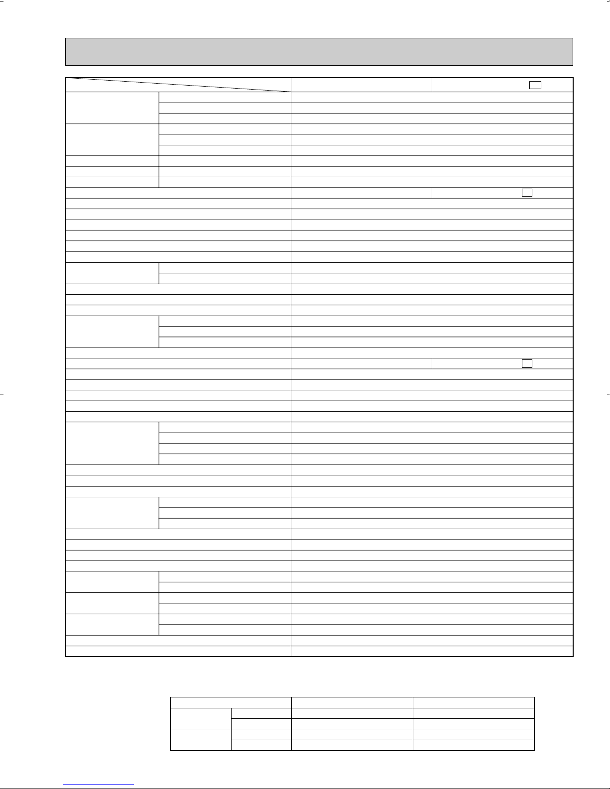
Item
Model
MSH12TN
MSH15TN
Capacity
Power
consumption
EER [SEER]
HSPF IV (V)
COP
INDOOR UNIT MODEL
External finish
Power supply
Max. fuse size (time delay)/ Disconnect switch
Min. circuit ampacity
Fan motor
Auxiliary heater
Airflow Low—Med.—High
Moisture removal
Sound level Low-Med.-High
Cond. drain connection O.D.
Dimensions
Weight
OUTDOOR UNIT MODEL
External finish
Power supply
Max. fuse size (time delay)
Min. circuit ampacity
Fan motor
Compressor
Refrigerant control
Sound level
Defrost method
Dimensions
Weight
REMOTE CONTROLLER
Control voltage (by built-in transformer)
REFRIGERANT PIPING
Pipe size
(Min. wall thickness)
Connection method
Between the indoor
& outdoor units
Refrigerant charge (R22)
Refrigerating oil (Model)
Btu/h
Btu/h
Btu/h
W
W
V, phase, Hz
A
A
F.L.A
A(kW)
CFM
CFM
pt./h
dB(A)
in.
in.
in.
in.
Ib.
V, phase, Hz
A
A
F.L.A
R.L.A
L.R.A
dB(A)
in.
in.
in.
Ib.
in.
in.
ft.
ft.
lb.
oz.
12,600/12,900
13,000/13,500
6,800/7,000
1,280/1,310
1,180/1,250
1,110/1,140
9.8/9.8[10.2/10.2]
3.23/3.17
311-339-388
3.3
15
0.42
RH189NHDT
49
30-23/32
10-1/32
21-1/4
86
1/2 (0.0285)
2 Ib. 12 oz.
6.8/6.8 (5.9/5.9)
White
115, 1, 60
15
0.6
0.43
–
360-395-452
36-39-42
5/8
39-15/16
7-1/2
12-5/8
31
Munsell 5Y7/1
208/230, 1, 60
14
C-R 1.68 C-S 2.78
10.0
35.0
Capillary tube
Reverse cycle
Wireless type
12V DC
Not supplied (optional parts)
1/4 (0.0265)
Flared
Flared
Max. 25
Max. 50
16.1 (MS56)
14,300/14,600
14,500/14,800
8,700/8,900
1,350/1,380
1,250/1,300
1,210/1,240
10.6/10.6 [10.7/10.7]
3.40/3.34
293-321-367
4.7
20
0.52
RH207NHDT
53
33-7/16
11-7/16
23-13/16
99
5/8 (0.0315)
3 lb. 3 oz.
❈1 ❈3
❈1
❈1
❈2
❈1
❈1
❈2
Cooling
Heating 47
Heating 17
Cooling
Heating 47
Heating 17
Cooling
Heating
Heating
(208/230V)
(208/230V)
(208/230V)
(208/230V)
(208/230V)
(208/230V)
(208/230V)
(208/230V)
(208/230V)
MSH12TN -
MSH15TN -
MSH12TN
MSH12TN -
U1
MSH15TN
MSH15TN -
U1
U1
MUH12TN
MUH12TN -
U1 U2
MUH15TN
MUH15TN -
U1 U2
U1
Dry
Wet
W
D
H
Model
Winding resistance (at 68˚F) Ω
W
D
H
Liquid
Gas
Indoor
Outdoor
Height difference
Piping length
Cooling
Heating
Maximum
Minimum
Maximum
Minimum
Indoor intake air temperature
95˚FDB, 71˚FWB
67˚FDB, 57˚FWB
80˚FDB, 67˚FWB
70˚FDB, 60˚FWB
Outdoor intake air temperature
115˚FDB
67˚FDB
75˚FDB, 65˚FWB
17˚FDB, 15˚FWB
NOTE : Test conditions are based on ARI 210/240.
❈1 : Rating conditions(cooling) — Indoor : 80˚FDB, 67˚FWB, Outdoor : 95˚FDB, (75˚FWB)
❈2 : (heating) — Indoor : 70˚FDB, 60˚FWB, Outdoor : 17˚FDB, 15˚FWB
❈3 : (cooling) — Indoor : 80˚FDB, 67˚FWB, Outdoor : 82˚FDB, 65˚FWB
Operating Range
(heating) — Indoor : 70˚FDB, 60˚FWB, Outdoor : 47˚FDB, 43˚FWB
12
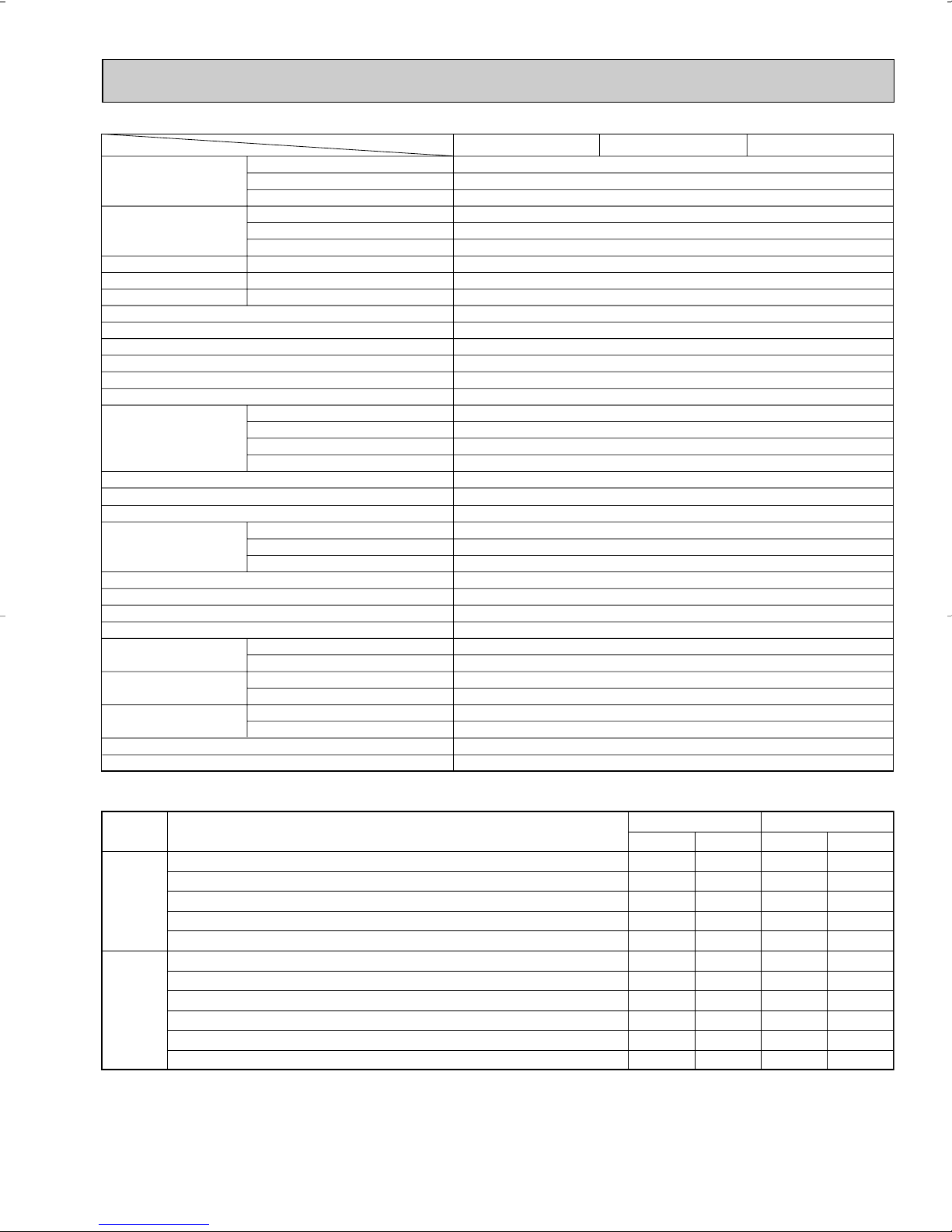
Item Model
❈1
Capacity
Power
consumption
❈1 ❈3
EER [SEER]
HSPF IV (V)
COP
Cooling
Heating 47
Heating 17
Cooling
❈1
Heating 47
Heating 17
Cooling
Heating
Heating
(208/230V)
❈1
(208/230V)
❈2
(208/230V)
(208/230V)
❈1
(208/230V)
❈2
(208/230V)
(208/230V)
(208/230V)
(208/230V)
Btu/h
Btu/h
Btu/h
INDOOR UNIT MODEL
W
W
MSH17TN
MSH17TN MSH17TN External finish
Power supply
Max. fuse size (time delay)/ Disconnect switch
Min. circuit ampacity
Fan motor
Auxiliary heater
Airflow Low—Med.—High
Dry
Wet
Moisture removal
Sound level Low-Med.-High
Cond. drain connection O.D.
W
Dimensions
D
H
Weight
OUTDOOR UNIT MODEL
V, phase, Hz
A
A
F.L.A
A(kW)
CFM
CFM
pt./h
dB(A)
in.
in.
in.
in.
lb.
MUH17TN MUH17TN External finish
Power supply
Max. fuse size (time delay)
Min. circuit ampacity
Fan motor
V, phase, Hz
A
A
F.L.A
Model
Compressor
Winding resistance (at 68˚F) Ω
R.L.A
L.R.A
Refrigerant control
Sound level
dB(A)
Defrost method
in.
in.
in.
lb.
Dimensions
Weight
W
D
H
REMOTE CONTROLLER
Control voltage (by built-in transformer)
REFRIGERANT PIPING
Pipe size
(Min. wall thickness)
Connection method
Between the indoor
& outdoor units
Liquid
Gas
Indoor
Outdoor
Height difference
Piping length
Refrigerant charge (R22)
Refrigerating oil (Model)
NOTE : Test conditions are based on ARI 210/240.
❈1 : Rating conditions (cooling) — Indoor : 80˚FDB, 67˚FWB, Outdoor : 95˚FDB, (75˚FWB)
❈2 : (heating) — Indoor : 70˚FDB, 60˚FWB, Outdoor : 17˚FDB, 15˚FWB
❈3 : (cooling) — Indoor : 80˚FDB, 67˚FWB, Outdoor : 82˚FDB, 65˚FWB
(heating) — Indoor : 70˚FDB, 60˚FWB, Outdoor : 47˚FDB, 43˚FWB
Operating Range
Cooling
Heating
Maximum
Minimum
Maximum
Minimum
in.
in.
ft.
ft.
lb.
oz.
Indoor intake air temperature
95˚FDB, 71˚FWB
67˚FDB, 57˚FWB
80˚FDB, 67˚FWB
70˚FDB, 60˚FWB
13
MSH17TN -
16,000/16,200
16,800/17,200
10,100/10,300
1,560/1,580
1,500/1,570
1,410/1,510
10.3/10.3 (10.4/10.4)
6.8/6.8 (5.9/5.9)
3.28/3.21
White
115, 1, 60
15
0.7
0.51
–
406-441-491
342-371-413
5.1
40-43-45
5/8
39-15/16
7-1/2
12-5/8
31
Munsell 5Y 7/1
208/230, 1, 60
20
15
0.75
RH231NHDT
C-R 1.65 C-S2.67
11.0
38.0
Capillary tube
53
Reverse cycle
34-1/4
11-5/8
33-1/2
128
Wireless type
12V DC
Not supplied (optional parts)
1/4 (0.0265)
5/8 (0.0315)
Flared
Flared
Max. 25
Max. 50
4lb. 14oz.
16.1 (MS56)
Outdoor intake air temperature
115˚FDB
67˚FDB
75˚FDB, 65˚FWB
17˚FDB, 15˚FWB
U1
U1
U1
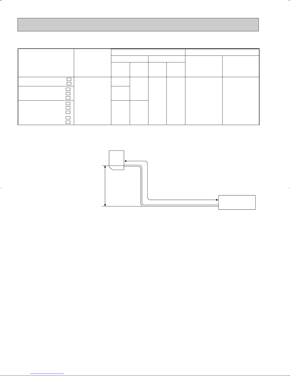
Indoor
unit
w Max. Height
difference 25ft.
Outdoor unit
Refrigerant Piping
Max.length
A
w Height difference should be within
25ft. regardless of which unit,
indoor or outdoor position is high.
Outside
diameter
Minimum
Wall
thickness
Outside
diameter
Minimum
Wall
thickness
MSH09TW
MUH09TW
MSH12TN
MUH12TN
MSH15TN
MUH15TN
MSH17TN
MUH17TN
MSH09TWMUH09TW-
MSH12TNMUH12TNMUH12TN-
MSH15TNMUH15TNMUH15TN-
MSH17TNMUH17TN-
Additional piping
Max. length : ft.
A
50
Gas
Piping size : in. Length of connecting pipe : in.
Liquid
Indoor unit
Outdoor unit
Model
U1
U1
U1
U1
U2
U1
U1
U2
U1
U1
Gas :
Liquid :00
Gas :
Liquid :
16-15/16
19-11/16
[ 3/8
[ 1/2
[ 5/8
[ 1/4
0.0285
0.0315
0.0265
MAX. REFRIGERANT PIPING LENGTH
MAX. HEIGHT DIFFERENCE
14
Item Model
Cooling
Heating
Mode
❈1: "A" Cooling Steady State at rated compressor Speed
❈3: "B-2" Cooling Steady State at rated compressor Speed
"B-1" Cooling Steady State at minimum compressor Speed
Low ambient Cooling Steady State at minimum compressor Speed
Intermediate Cooling Steady State At Intermediate compressor Speed
w
❈1: Standard Rating-Heating at rated compressor Speed
❈2: Low temperature Heating at rated compressor Speed
Max temperature Heating at minimum compressor Speed
High temperature Heating at minimum compressor Speed
Frost Accumulation at rated compressor Speed
Frost Accumulation at Intermediate compressor Speed
w
Test
Indoor air condition Outdoor air condition
Dry bulb
Wet bulb
Dry bulb
Wet bulb
80
80
80
80
80
70
70
70
70
70
70
67
67
67
67
67
60
60
60
60
60
60
95
82
82
67
87
47
17
62
47
35
35
(75)
(65)
(65)
(53.5)
(69)
43
15
56.5
43
33
33
w
At Intermediate compressor Speed
=("Cooling rated compressor speed" - "minimum compressor speed") / 3 + "minimum compressor speed".
Unit: ˚F
Capacity
Power
consumption
❈1 ❈3
EER [SEER]
HSPF IV (V)
COP
Cooling
❈1
Heating 47
Heating 17
Cooling
❈1
Heating 47
Heating 17
Cooling
Heating
Heating
❈1
❈2
❈1
❈2
Btu/h
Btu/h
Btu/h
OUTDOOR UNIT MODEL
External finish
Power supply
V, phase, Hz
Max. fuse size (time delay)
Min. circuit ampacity
Fan motor
F.L.A
Model
Compressor
Winding resistance (at 68˚F) Ω
R.L.A
L.R.A
Refrigerant control
Sound level
dB(A)
Defrost method
W
Dimensions
D
H
Weight
REMOTE CONTROLLER
Control voltage (by built-in transformer)
REFRIGERANT PIPING
Pipe size
(Min. wall thickness)
Connection method
Between the indoor
& outdoor units
Liquid
Gas
Indoor
Outdoor
Height difference
Piping length (a+b+c)
Refrigerant charge (R22)
Refrigerating oil (Model)
W
W
in.
in.
in.
lb.
in.
in.
ft.
ft.
lb.
oz.
Triple-Unit Double-Unit Single-Unit
28,400/(9,940~30,500)
28,600/(9,040~38,000)
(18,100)
3,800/(810~4,610)
2,800/(710~3,970)
(2,310)
11.0
7.5
3.08
MXZ30TN MXZ30TN2
Munsell 5Y 8/1
208/230, 1, 60
A
A
30
25
1.0
THV-247FBA
U-V 0.61 V-W 0.61 W-U 0.61
15
72
LEV
47
Reverse cycle
35-7/16
12-19/32 (+1+3/8)
35-7/16
176
Wireless type
12V DC
Not supplied (optional parts)
1/4 (0.0265)
A:1/2(0.0285), B,C:3/8(0.0285)
Flared
Flared
Max. 33
Max. 200
8lb. 10oz.
26.7 (MS56)
NOTE : Test conditions are based on ARI 210/240.
15
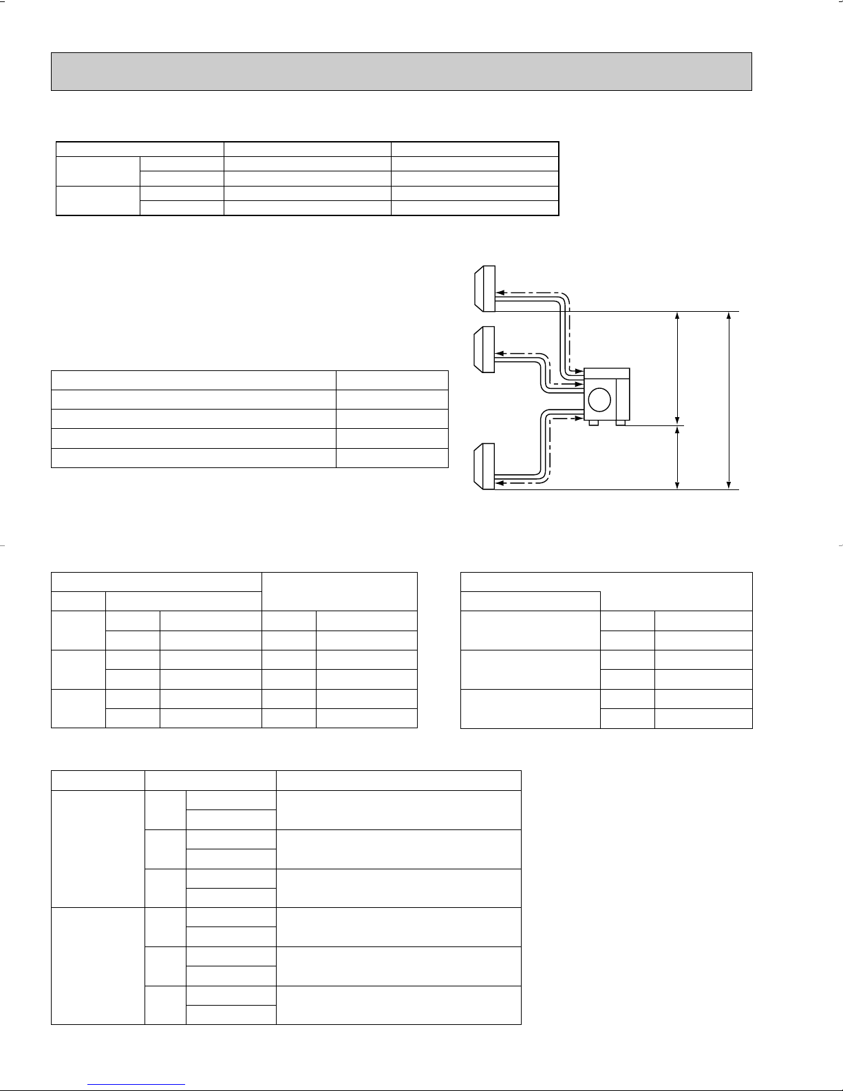
a
b
c
Outdoor
unit
Indoor
units
H
H
H
Liquid {1/4
Gas {3/8
Liquid {1/4
Gas {1/2
Liquid {1/4
Gas {5/8
Liquid {1/4
Gas {3/8
Liquid {1/4
Gas {1/2
Liquid {1/4
Gas {5/8
Use a different-diameter pipe of the option
MAC-455JP ({1/2 ➔ {3/8)
Use a different-diameter pipe of the option
MAC-456JP ({1/2 ➔ {5/8)
Indoor unit can be connected directly
Indoor unit can be connected directly
Use a different-diameter pipe of the option
MAC-454JP ({3/8 ➔ {1/2)
It is not possible to connect
09
12
15/17
09
12
15/17
Outdoor unit
A
Liquid {1/4
Gas {1/2
B, C
Liquid {1/4
Gas {3/8
Indoor unit Connection method
Cooling
Heating
Maximum
Minimum
Maximum
Minimum
Indoor intake air temperature
95˚FDB, 71˚FWB
67˚FDB, 57˚FWB
80˚FDB, 67˚FWB
70˚FDB, 60˚FWB
Outdoor intake air temperature
115˚FDB
67˚FDB
75˚FDB, 65˚FWB
17˚FDB, 15˚FWB
Operating Range MXZ30TN MXZ30TN2
MAX. REFRIGERANT PIPING LENGTH & PIPE SIZE SELECTION
MXZ30TN MXZ30TN2
Piping length each indoor unit (a, b, c) 82ft. MAX.
Total piping length (a+b+c) 200ft. MAX.
Height difference between units (H) 33ft. MAX.
Bending point for each unit 25 MAX.
Total bending point 60 MAX.
❋It does not matter which unit is higher.
● Refrigerant pipe diameter is different according to indoor unit to be connected. When using extension pipes,refer to the
tables below.
● When diameter of refrigerant pipe is different from that of outdoor unit union, use optional Different-diameter pipe.
For further information on Different-diameter pipe,see page 128.
Indoor unit
class Pipe diameter
09
12
15/17
Liquid 1/4 Liquid 1/4
Gas 3/8 Gas 3/8
Liquid 1/4 Liquid 1/4
Gas 1/2 Gas 1/2
Liquid 1/4 Liquid 1/4
Gas 5/8 Gas 5/8
Extension pipe diameter
Outdoor unit union diameter
For
Indoor unit A
Indoor unit B
Indoor unit C
Liquid 1/4
Gas 1/2
Liquid 1/4
Gas 3/8
Liquid 1/4
Gas 3/8
Unit : inch
● Please connect the indoor unit and the outdoor unit as shown in the table below.
16
6
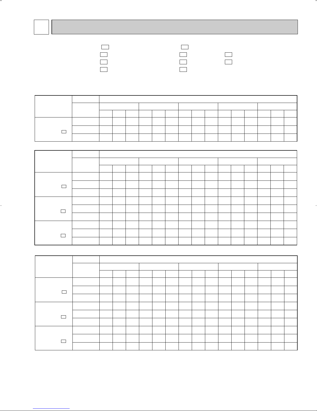
Model
Indoor air Outdoor intake air DB temperature(˚F
)
71
67
63
71
67
63
71
67
63
TC
15.8
15.0
14.1
17.9
16.9
15.9
19.8
18.8
17.7
SHC
9.1
10.6
11.9
9.2
11.0
12.5
10.1
12.0
13.7
TPC
1.17
1.10
1.05
1.23
1.16
1.10
1.41
1.33
1.26
TC
14.8
13.9
13.0
16.7
15.8
14.7
18.5
17.5
16.4
SHC
8.5
9.9
11.0
8.6
10.2
11.6
9.4
11.2
12.7
TPC
1.28
1.21
1.16
1.35
1.28
1.22
1.54
1.46
1.40
TC
13.9
12.9
12.1
15.7
14.6
13.7
17.4
16.2
15.2
SHC
8.0
9.2
10.2
8.1
9.5
10.8
8.8
10.4
11.8
TPC
1.38
1.31
1.25
1.45
1.38
1.32
1.66
1.58
1.51
TC
12.9
12.0
11.0
14.6
13.6
12.5
16.2
15.1
13.9
SHC
7.4
8.5
9.3
7.5
8.8
9.8
8.2
9.6
10.7
TPC
1.45
1.39
1.34
1.52
1.46
1.41
1.75
1.67
1.61
TC
11.9
11.0
10.1
13.4
12.5
11.4
14.9
13.9
12.6
SHC
6.8
7.8
8.5
6.9
8.1
8.9
7.6
8.9
9.8
TPC
1.51
1.45
1.39
1.59
1.53
1.46
1.82
1.75
1.67
IWB
(˚F)
75 85 95 105 115
MSH12TN
MSH12TN -
MSH15TN
MSH15TN -
MSH17TN
MSH17TN -
NOTE 1. IWB : Intake air wet-bulb temperature
TC : Total Capacity (x10
3
Btu/h), SHC : Sensible Heat Capacity (x10
3
Btu/h)
TPC : Total Power Consumption (kW)
2. SHC is based on 80˚F of indoor intake air DB temperature.
U1
U1
U1
(230V)
DATA
MSH09TW
MSH12TN
MSH15TN
MSH17TN
MSH09TW MSH12TN MSH15TN MSH17TN -
6-1. PERFORMANCE DATA
1) COOLING CAPACITY
(115V)
Indoor air Outdoor intake air DB temperature(˚F
MSH09TW
MSH09TW -
(208V)
MSH12TN
MSH12TN -
MSH15TN
MSH15TN -
MSH17TN
MSH17TN -
Model
U1
Model
U1
U1
U1
IWB
(˚F)
71
67
63
Indoor air Outdoor intake air DB temperature(˚F
IWB
(˚F)
71
67
63
71
67
63
71
67
63
U1
MUH09TW
U1
MUH12TN
U1
MUH15TN
U1
MUH17TN
75 85 95 105 115
TC
SHC
TPC
10.8
6.1
0.79
10.2
7.1
0.75
9.6
8.0
0.71
75 85 95 105 115
TC
SHC
TPC
15.4
8.9
1.14
14.6
10.4
1.08
13.7
11.6
1.02
17.5
9.1
1.20
16.6
10.8
1.13
15.6
12.2
1.08
19.6
9.9
1.39
18.6
11.9
1.31
17.4
13.5
1.25
MUH09TW MUH12TN - MUH12TN MUH15TN - MUH15TN MUH17TN -
TC
SHC
10.1
5.7
9.5
6.7
8.9
7.4
TC
SHC
14.4
8.3
13.6
9.7
12.7
10.7
16.4
8.5
15.4
10.0
14.4
11.3
18.3
9.3
17.3
11.1
16.2
12.5
TPC
0.87
0.82
0.79
TPC
1.25
1.18
1.13
1.32
1.25
1.19
1.52
1.44
1.38
U1
U1
TC
9.5
8.8
8.3
TC
13.5
12.6
11.8
15.4
14.3
13.4
17.2
16.0
15.0
SHC
5.4
6.2
6.9
SHC
7.8
8.9
10.0
7.9
9.3
10.5
8.7
10.2
11.6
TPC
0.93
0.89
0.85
TPC
1.34
1.28
1.22
1.42
1.35
1.29
1.64
1.56
1.49
TC
8.8
8.2
7.5
TC
12.6
11.7
10.8
14.3
13.3
12.2
16.0
14.9
13.7
U2U1
U2U1
)
SHC
5.0
5.7
6.3
)
SHC
7.3
8.3
9.1
7.4
8.6
9.6
8.1
9.5
10.6
TPC
0.98
0.94
0.91
TPC
1.41
1.36
1.31
1.49
1.43
1.38
1.72
1.65
1.59
TC
8.1
7.5
6.9
TC
11.6
10.8
9.8
13.2
12.2
11.2
14.7
13.7
12.5
SHC
4.6
5.3
5.7
SHC
6.7
7.6
8.3
6.8
7.9
8.7
7.5
8.8
9.7
TPC
1.02
0.99
0.94
TPC
1.47
1.42
1.36
1.55
1.50
1.43
1.79
1.73
1.65
17
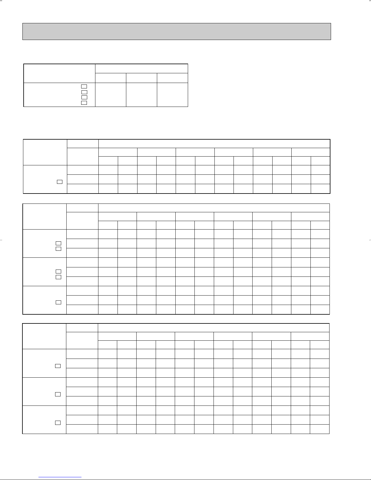
Model
Refrigerant piping length (one way : ft.)
1.0
25 (std.)
0.954
40
0.927
49
MSH09TW
MSH12TN
MSH15TN
MSH17TN
MSH09TWMSH12TNMSH15TNMSH17TN-
U1
U1
U1
U1
2) COOLING CAPACITY CORRECTIONS
(230V)
Model
Indoor air Outdoor intake air WB temperature(˚F
)
75
70
65
75
70
65
75
70
65
TC
7.8
8.3
8.5
8.6
9.1
9.3
10.0
10.6
10.8
TPC
0.93
0.90
0.86
0.97
0.94
0.90
1.17
1.13
1.08
TC
9.8
10.1
10.6
10.7
11.1
11.6
12.5
12.9
13.5
TPC
1.09
1.07
1.03
1.14
1.11
1.07
1.37
1.34
1.30
TC
11.7
11.9
12.4
12.8
13.1
13.5
14.9
15.2
15.7
TPC
1.22
1.19
1.16
1.27
1.24
1.20
1.53
1.49
1.45
TC
13.2
13.5
13.9
14.4
14.8
15.2
16.8
17.2
17.7
TPC
1.28
1.25
1.22
1.33
1.30
1.27
1.61
1.57
1.53
TC
13.6
13.9
14.3
14.9
15.2
15.7
17.3
17.7
18.2
TPC
1.30
1.28
1.24
1.35
1.33
1.29
1.63
1.60
1.55
TC
15.4
15.7
16.1
16.9
17.2
17.6
19.6
20.0
20.5
TPC
1.35
1.33
1.30
1.40
1.38
1.35
1.70
1.66
1.63
IDB
(˚F)
15 25 35 43 45 55
MSH12TN
MSH12TN -
U1
MSH15TN
MSH15TN -
U1
MSH17TN
MSH17TN -
U1
NOTE: 1. IDB : Intake air dry-bulb temperature
TC : Total Capacity (x10
3
Btu/h)
TPC : Total Power Consumption (kW)
2. Above data is for heating operation without any frost.
(208V)
Model
Indoor air Outdoor intake air WB temperature(˚F
)
75
70
65
75
70
65
75
70
65
TC
7.5
8.0
8.2
8.4
8.9
9.1
9.7
10.3
10.6
TPC
0.88
0.85
0.81
0.93
0.90
0.86
1.12
1.08
1.04
TC
9.4
9.8
10.2
10.5
10.9
11.4
12.2
12.6
13.2
TPC
1.03
1.01
0.97
1.09
1.07
1.03
1.31
1.28
1.24
TC
11.2
11.5
11.9
12.5
12.8
13.3
14.5
14.9
15.4
TPC
1.15
1.12
1.09
1.22
1.19
1.16
1.46
1.43
1.39
TC
12.7
13.0
13.4
4.1
14.5
14.9
16.4
16.8
17.3
TPC
1.21
1.18
1.15
1.28
1.25
1.22
1.54
1.50
1.46
TC
13.1
13.4
13.8
14.6
14.9
15.4
16.9
17.3
17.8
TPC
1.23
1.20
1.17
1.30
1.28
1.24
1.56
1.53
1.49
TC
14.8
15.1
15.5
16.5
16.9
17.3
19.2
19.6
20.0
TPC
1.27
1.25
1.23
1.35
1.33
1.30
1.62
1.59
1.56
IDB
(˚F)
15 25 35 43 45 55
MSH12TN
MSH12TN -
U1
MSH12TN - U2
MSH15TN
MSH15TN -
U1
MSH15TN - U2
MSH17TN
MSH17TN -
U1
(115V)
Model
Indoor air Outdoor intake air WB temperature(˚F
)
75
70
65
TC
6.1
6.5
6.6
TPC
0.66
0.64
0.61
TC
7.6
7.9
8.2
TPC
0.78
0.76
0.73
TC
9.1
9.3
9.6
TPC
0.87
0.85
0.82
TC
10.2
10.5
10.8
TPC
0.91
0.89
0.87
TC
10.6
10.8
11.1
TPC
0.93
0.91
0.88
TC
12.0
12.2
12.5
TPC
0.96
0.94
0.93
IDB
(˚F)
15 25 35 43 45 55
MSH09TW
MSH09TW -
U1
3) HEATING CAPACITY
18
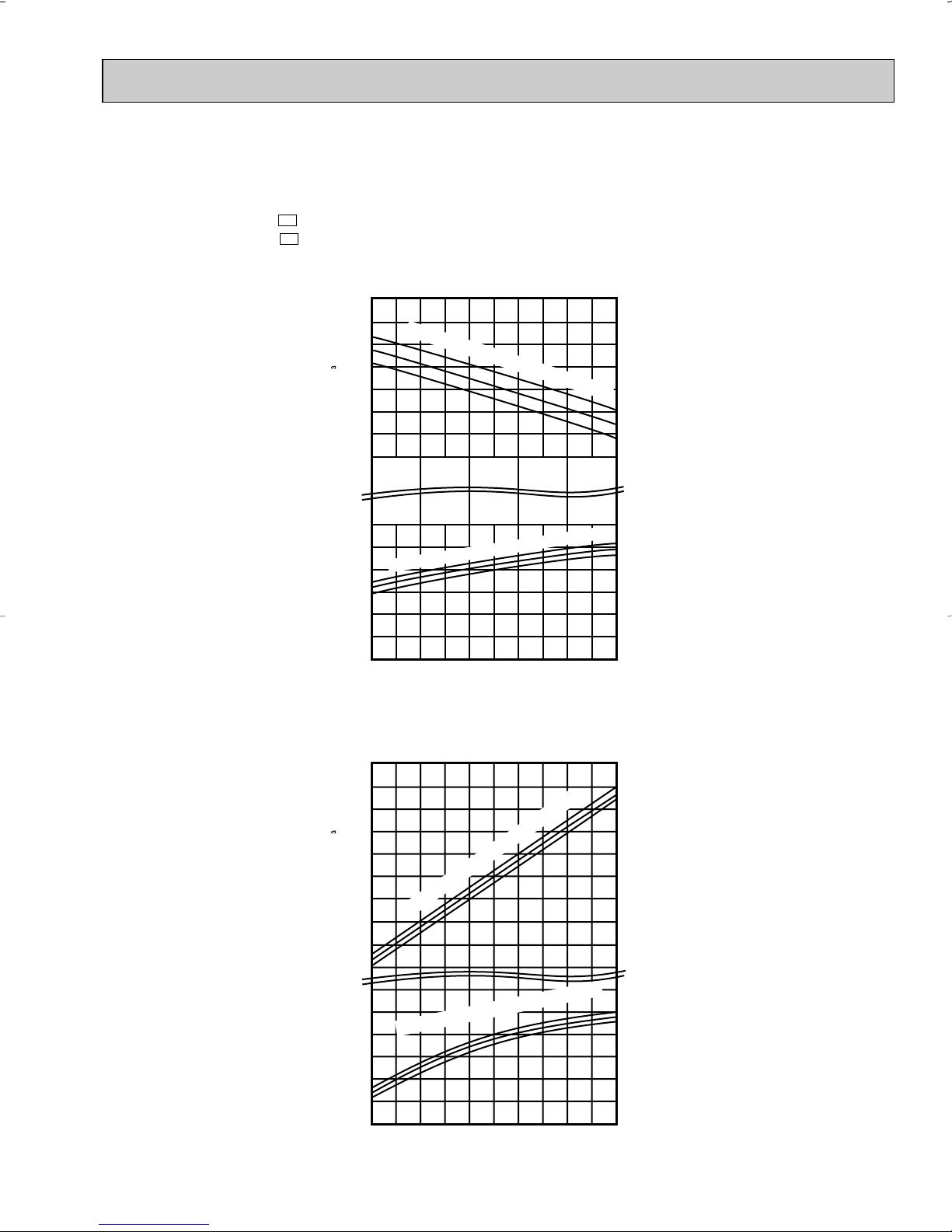
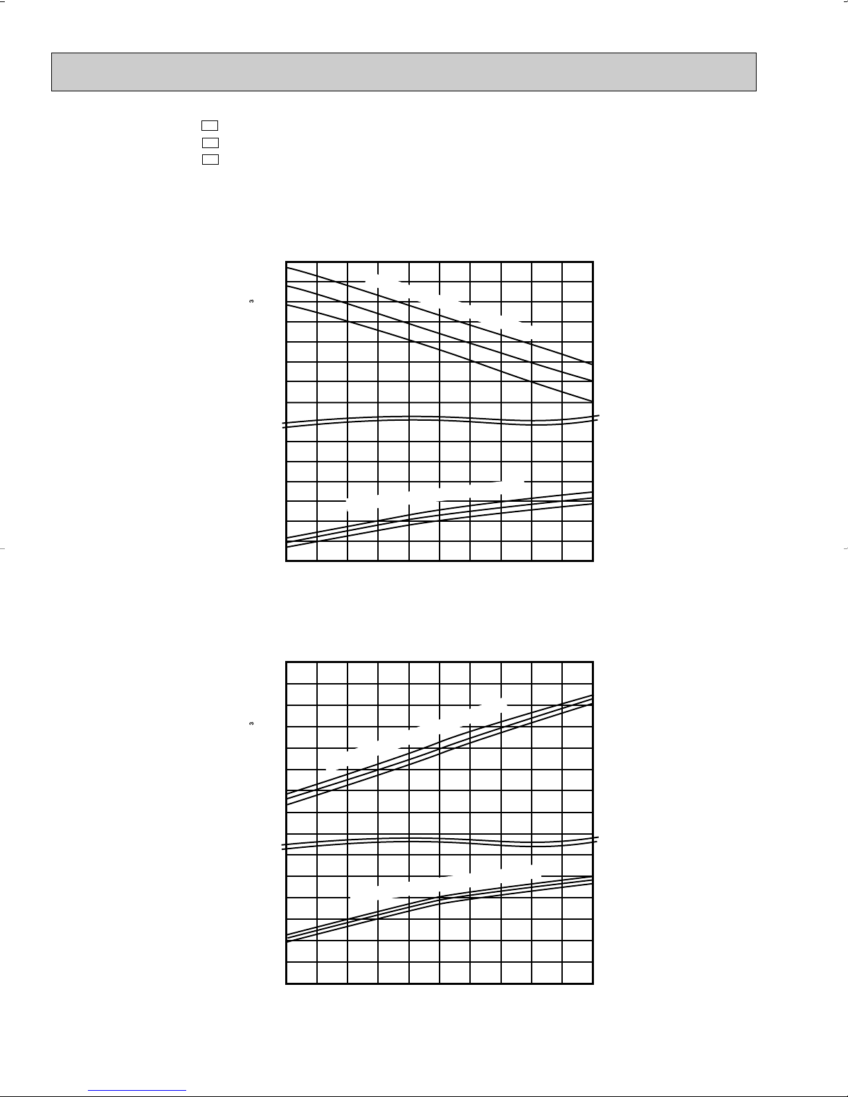
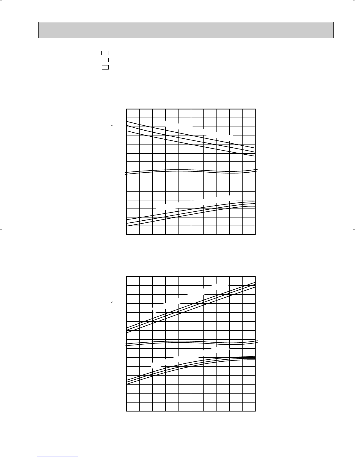
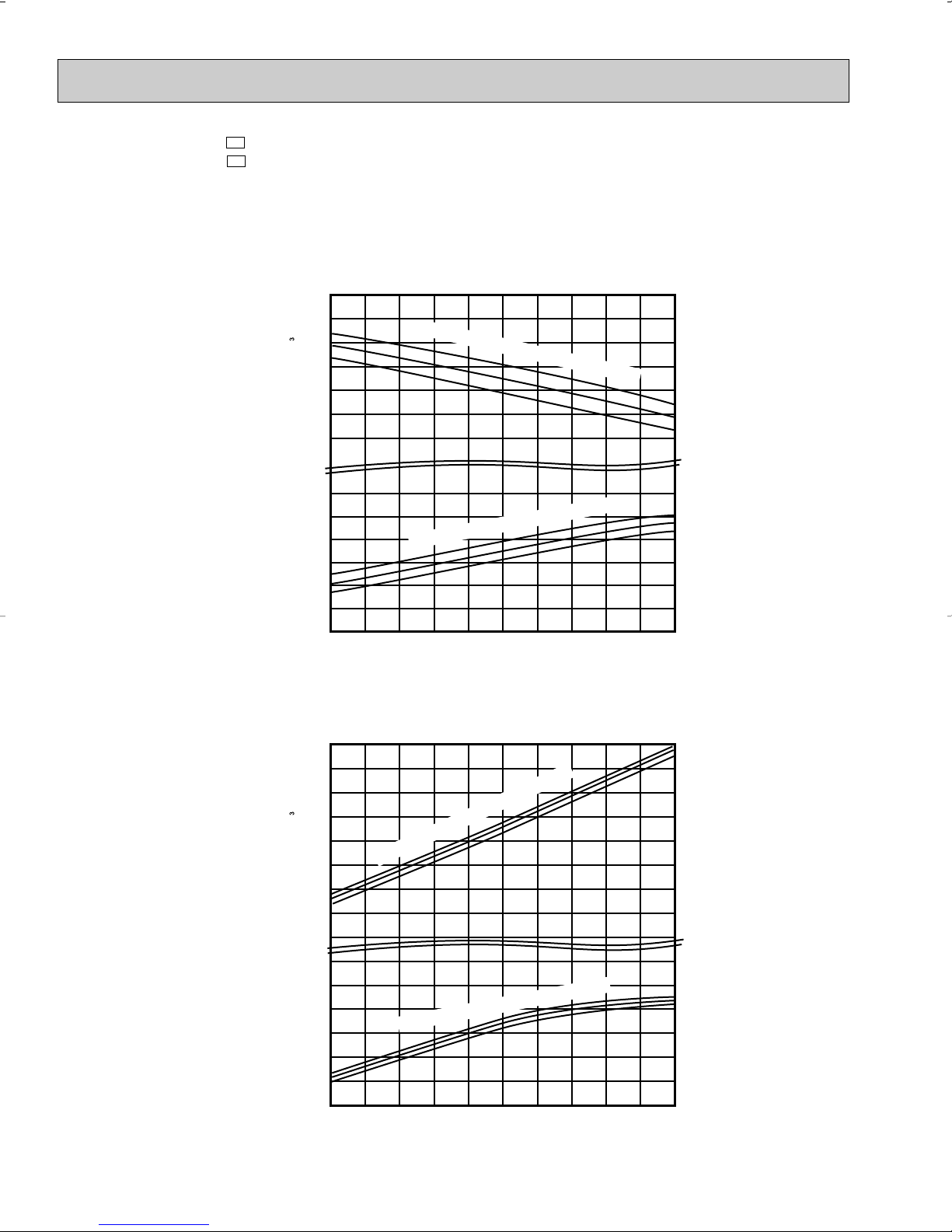
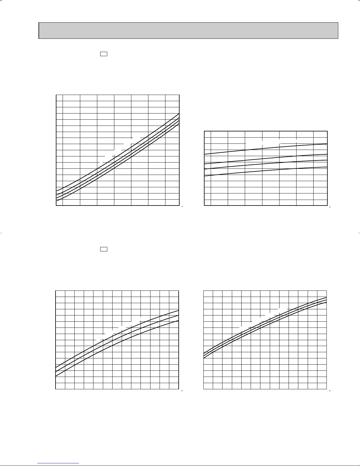
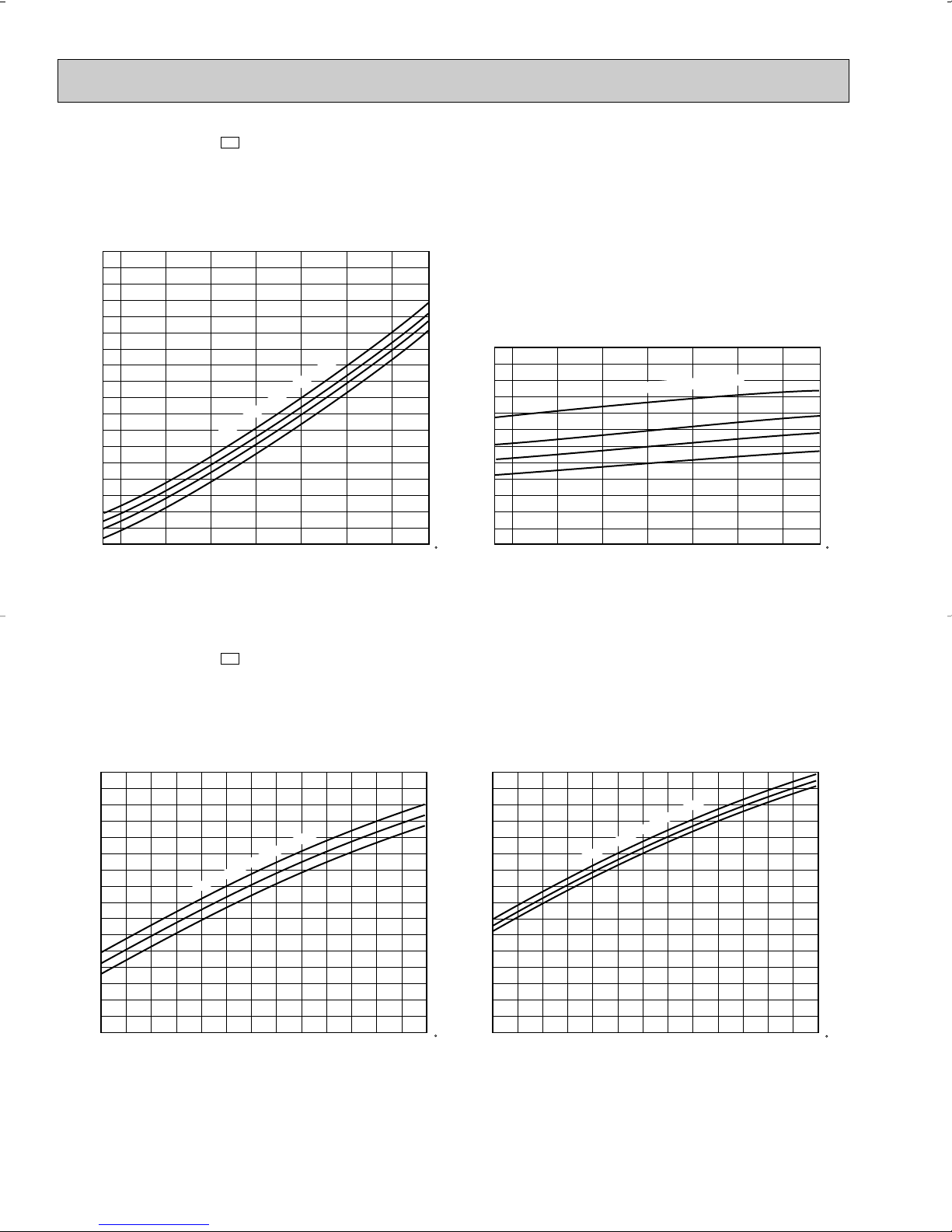
6-2. PERFORMANCE CURVE
71
67
63
71
67
63
65
70
75
75
70
65
Total power consumption (kW) Total capacity ( ✕10 Btu/h)
Outdoor intake air DB temperature (°F)
Indoor intake air WB temperature (
°F)
Indoor intake air WB temperature (
°F)
Cooling
SHF at rating condition = 0.70
= 233CFM
= 0.23
Airflow
Bypass Factor
12
10
8
6
1.2
65 75 85 95 105 115
0.8
0.6
Total power consumption (kW) Total capacity ( ✕10 Btu/h)
Outdoor intake air WB temperature (°F)
Indoor intake air DB temperature (°F)
Indoor intake air DB temperature (
°F)
Heating
= 297CFM
Airflow
12
14
10
8
6
1.1
1.0
15 25 35 45 55
0.8
0.6
0.7
0.9
1.0
NOTE : The curves shows peformance under 230V AC.
As for under 208V AC, refer to PERFORMANCE DATAon page 17 and 18.
MSH09TW
MUH09TW
MSH09TW MUH09TW -
U1
U1
19
MSH12TN
71
67
63
71
67
63
16
14
10
12
2
1
Indoor intake air WB temperature (
°
F)
Indoor intake air WB temperature (
°
F)
65
70
75
75
70
65
20
16
8
12
1.6
0.6
Cooling
SHF at rating condition = 0.71
= 388CFM
= 0.15
Airflow
Bypass Factor
65 75 85 95 105 115
Total power consumption (kW) Total capacity ( ✕10 Btu/h)
Outdoor intake air DB temperature (°F)
Indoor intake air DB temperature (
°
F)
Heating
= 452CFM
Airflow
15 25 35 45 55
Total power consumption (kW) Total capacity ( ✕10 Btu/h)
Outdoor intake air WB temperature (°F)
0.8
1.0
1.2
1.4
Indoor intake air DB temperature (
°
F)
MUH12TN
MSH12TN MUH12TN MUH12TN -
U1
U1
U2
20
MSH15TN
71
67
63
71
67
63
65
70
75
75
70
65
Indoor intake air WB temperature (
°
F)
Cooling
SHF at rating condition = 0.65
= 367CFM
= 0.22
Airflow
Bypass Factor
65 75 85 95 105 115
Total power consumption (kW) Total capacity ( ✕10 Btu/h)
22
18
14
10
2
Outdoor intake air DB temperature (°F)
Indoor intake air DB temperature (
°
F)
Heating
= 452CFM
Airflow
15 25 35 45 55
Total power consumption (kW) Total capacity ( ✕10 Btu/h)
20
16
8
1.4
0.8
Outdoor intake air WB temperature (°F)
1
12
1.0
1.2
0.6
Indoor intake air DB temperature (
°
F)
Indoor intake air WB temperature (
°
F)
MUH15TN
MSH15TN MUH15TN MUH15TN -
U1
U1
U2
21
MSH17TN
71
67
63
71
67
63
65
70
75
75
70
65
Indoor intake air WB temperature (
°
F)
Indoor intake air WB temperature (
°
F)
Cooling
SHF at rating condition = 0.64
= 413CFM
= 0.24
Airflow
Bypass Factor
65 75 85 95 105 115
Total power consumption (kW) Total capacity ( ✕10 Btu/h)
24
20
16
12
2
1
Outdoor intake air DB temperature (°F)
Indoor intake air DB temperature (
°
F)
Indoor intake air DB temperature (
°
F)
Heating
= 491CFM
Airflow
15 25 35 45 55
Total power consumption (kW) Total capacity ( ✕10 Btu/h)
20
16
12
8
2.0
1.0
Outdoor intake air WB temperature (°F)
1.2
1.6
1.4
1.8
MUH17TN
MSH17TN MUH17TN -
U1
U1
22
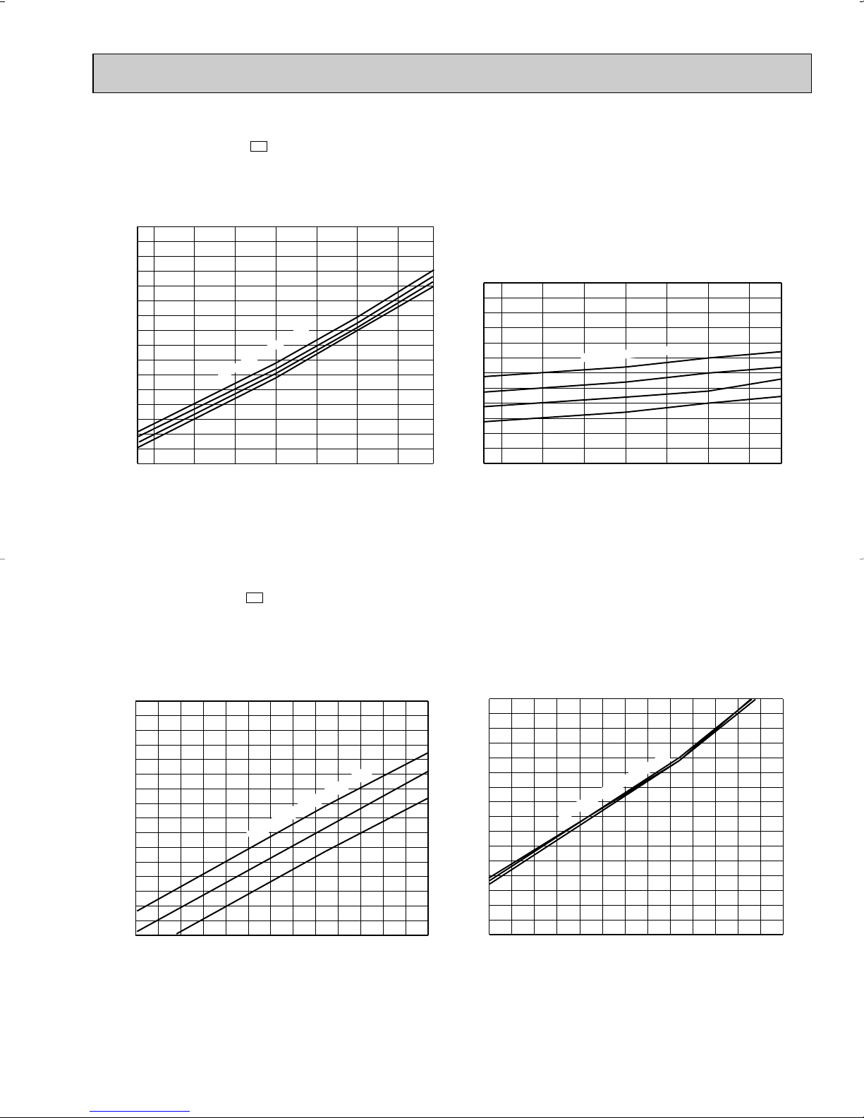
6-3. Condensing pressure
MSH09TW MSH09TW -
U1
(Cooling)
(PSIG)
300
Data is based on the condition of indoor humidity 50%.
Air flow should be set to High speed.
280
260
240
220
200
Condensing pressure
180
160
140
68 70 75 80 85 90 95 100 104(°F)
MSH09TW MSH09TW-
Indoor DB temperature (
Outdoor ambient temperature
U1
(Heating)
°F)
Data is based on the condition of outdoor humidity 75%.
Air flow should be set to High speed.
Data is for heating operation without any frost.
86
(PSIG)
80
75
100
70
90
80
70
60
Suction pressure
50
40
68 70 75 80 85 90 95 100 104(°F)
Indoor DB temperature (°F)
Outdoor ambient temperature
86
80
75
70
(PSIG)
310
300
290
280
270
260
250
240
230
220
210
200
Condensing pressure
190
180
170
160
150
5 10152025303540455055606570(°F)
Indoor DB temperature(
Outdoor ambient temperature
°F)
75
70
65
23
(PSIG)
80
70
60
50
40
30
Suction pressure
20
10
5 10152025303540455055606570(°F)
Indoor DB temperature (°F)
Outdoor ambient temperature
75 70 65

MSH12TN MSH12TN(Cooling)
(PSIG)
320
U1
Data is based on the condition of indoor humidity 50%.
Air flow should be set to High speed.
300
280
260
240
220
Condensing pressure
200
180
160
140
68 70 75 80 85 90 95 100 104(°F)
MSH12TN MSH12TN -
Indoor DB temperature (
Outdoor ambient temperature
U1
(Heating)
°F)
Data is based on the condition of outdoor humidity 75%.
Air flow should be set to High speed.
Data is for heating operation without any frost.
86
80
75
70
(PSIG)
100
90
80
70
Suction pressure
60
50
40
Indoor DB temperature (°F)
68 70 75 80 85 90 95 100 104(°F)
Outdoor ambient temperature
86
80
75
70
(PSIG)
310
300
290
280
270
260
250
240
230
220
210
200
Condensing pressure
190
180
170
160
150
5 10152025303540455055606570(°F)
Indoor DB temperature(°F)
Outdoor ambient temperature
(PSIG)
(PSIG)
80
70
60
75
50
70
40
65
30
Suction pressure
Suction pressure
20
10
24
75 70 65
Indoor DB temperature (°F)
Indoor DB temperature (°F)
10 15 20 25 30 35 40 45 50 55 60 65 70(°F)
5
Outdoor ambient temperature
MSH15TN MSH15TN(Cooling)
(PSIG)
320
U1
Data is based on the condition of indoor humidity 50%.
Air flow should be set to High speed.
300
280
260
240
220
200
Condensing pressure
180
160
140
68 70 75 80 85 90 95 100 104( F)
MSH15TN MSH15TN(Heating)
Indoor DB temperature (°F)
Outdoor ambient temperature
U1
Data is based on the condition of outdoor humidity 75%.
Air flow should be set to High speed.
Data is for heating operation without any frost.
86
80
75
70
(PSIG)
100
90
80
70
60
Suction pressure
50
40
68 70 75 80 85 90 95 100 104( F)
Indoor DB temperature (°F)
Outdoor ambient temperature
86
80
75
70
(PSIG)
290
280
270
260
250
240
230
220
210
200
Condensing pressure
190
180
170
160
150
510152025303540455055606570( F)
Indoor DB temperature(
Outdoor ambient temperature
°F)
75
70
65
(PSIG)
25
80
70
60
50
40
30
Suction pressure
20
10
510152025303540455055606570( F)
Indoor DB temperature (
Outdoor ambient temperature
°F)
75
70
65
MSH17TN MSH17TN(Cooling)
(PSIG)
320
U1
Data is based on the condition of indoor humidity 50%.
Air flow should be set to High speed.
300
280
260
240
220
Indoor DB temperature (°F)
200
Condensing pressure
180
160
140
68 70 75 80 85 90 95 100 104( F)
MSH17TN MSH17TN(Heating)
Outdoor ambient temperature
U1
Data is based on the condition of outdoor humidity 75%.
Air flow should be set to High speed.
Data is for heating operation without any frost.
86
80
75
70
(PSIG)
100
90
80
70
60
Suction pressure
50
40
68 70 75 80 85 90 95 100 104( F)
Indoor DB temperature (°F)
Outdoor ambient temperature
86
80
75
70
(PSIG)
300
290
280
270
260
250
240
230
220
210
200
Condensing pressure
190
180
170
160
150
510152025303540455055606570( F)
Indoor DB temperature(
Outdoor ambient temperature
°F)
75
70
65
(PSIG)
26
80
70
60
50
40
30
Section pressure
20
10
510152025303540455055606570( F)
Indoor DB temperature (
Outdoor ambient temperature
°F)
75
70
65
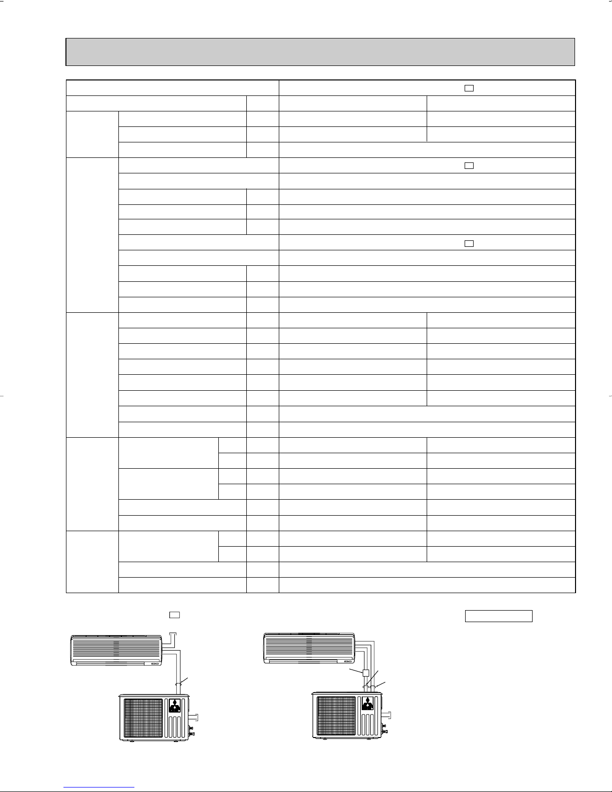
6-4. STANDARD OPERATION DATA
MSH09TW MSH09TW - U1
INDOOR UNIT
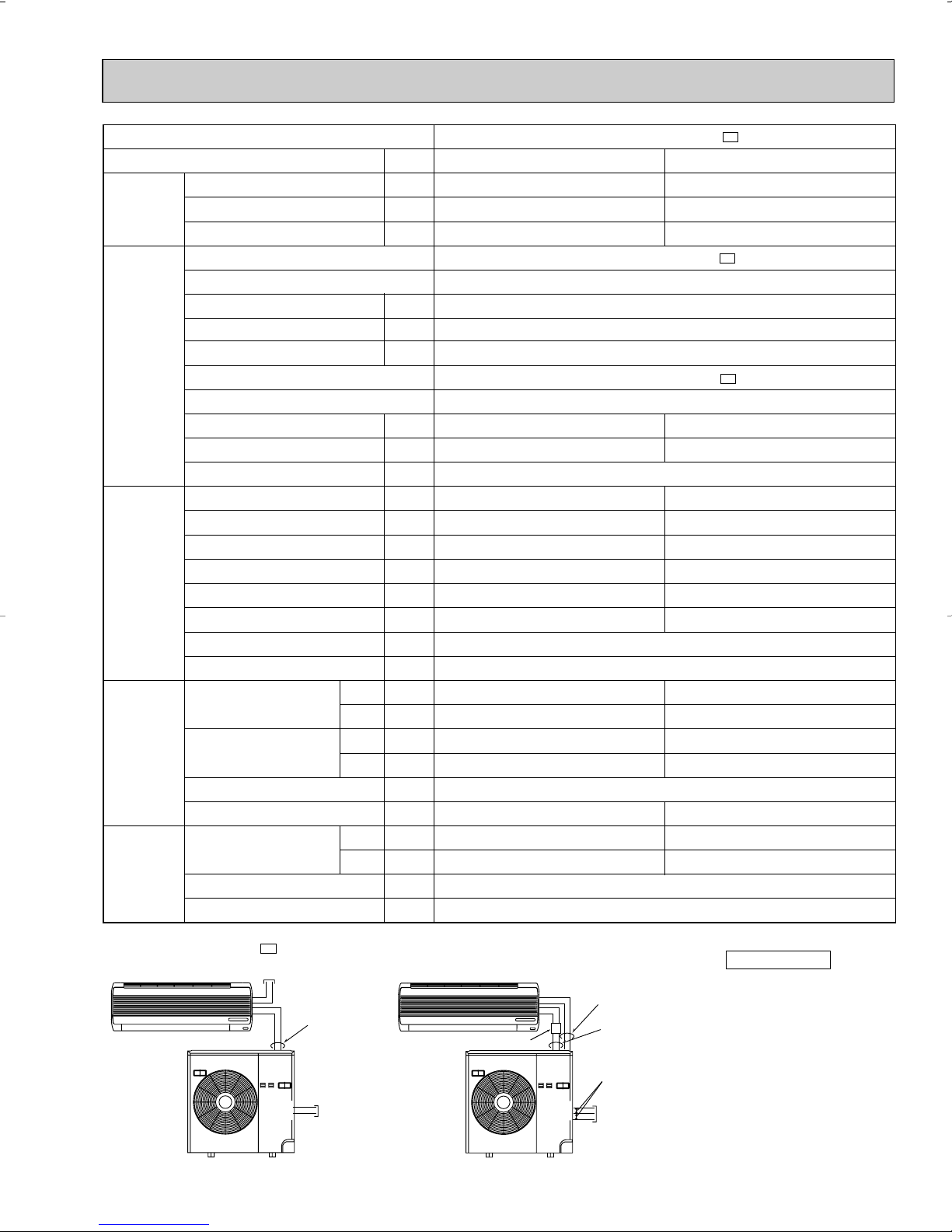
115V 60Hz 1[, 2 wires
•Both wirings can be applied to all MODELS.
OUTDOOR UNIT
115V
60Hz 1[, 2 wires
SIGNAL WIRE
2 wires 12V DC
INDOOR UNIT
OUTDOOR UNIT
115V
60Hz 1[, 2 wires
SIGNAL WIRE
2 wires 12V DC
115V 60Hz 1[,
2 wires
Disconnect
switch
Model
Item
Capacity
Total
Electrical
circuit
Refrigerant
circuit
Indoor
unit
Outdoor
unit
SHF
Input
Indoor unit
Power supply (V, phase, Hz)
Input
Fan motor current
Aux. heater current
Outdoor unit
Power supply (V, phase, Hz)
Input
Comp. current
Fan motor current
Condensing pressure
Suction pressure
Discharge temperature
Condensing temperature
Suction temperature
Comp. shell bottom temp
Ref. pipe length
Refrigerant charge (R22)
Intake air temperature
Discharge air temperature
Fan speed (High)
Airflow (High)
Intake air temperature
Fan speed
Airflow
DB
WB
DB
WB
DB
WB
Unit
Btu / h
—
kW
kW
A
A
kW
A
A
PSIG
PSIG
˚F
˚F
˚F
˚F
ft.
—
˚F
˚F
˚F
˚F
rpm
CFM
˚F
˚F
rpm
CFM
Cooling
8,800
0.70
235
70
179
113
52
157
80
67
59
57
950
233(Wet)
95
–
MSH09TW MSH09TW -
0.89
MSH09TW MSH09TW -
115,1,60
0.035
0.34
–
MUH09TW MUH09TW -
115, 1, 60
0.855
6.91
0.59
25
2 lb. 3 oz.
640
985
U1
Heating
10,500
–
U1
U1
223
60
171
110
35
146
70
60
100
–
1,000
297(Dry)
47
43
POWER SUPPLY
27
✻ Control voltage
Power supply voltage to serial
signal circuit is 12V DC.
11
Peak voltage between
and 33+ on in-out terminal
block is 12V DC .
Cooling
12,600/12,900
0.71
1.28/1.31
1.233/1.263
5.74/5.21
259
84
194
120
67
177
80
67
57
56
388[Wet]
95
–
Capacity (208/230V)
SHF
Input (208/230V)
Indoor unit
Power supply (V, phase, Hz)
Input
Fan motor current
Aux. heater current
Outdoor unit
Power supply (V, phase, Hz)
Input (208/230V)
Comp. current (208/230V)
Fan motor current
Condensing pressure
Suction pressure
Discharge temperature
Condensing temperature
Suction temperature
Comp. shell bottom temp
Ref. pipe length
Refrigerant charge (R22)
Intake air temperature
Discharge air temperature
Fan speed (High)
Airflow (High)
Intake air temperature
Fan speed (208/230V)
Airflow (208/230V)
Unit
Btu / h
—
kW
kW
A
A
kW
A
A
PSIG
PSIG
˚F
˚F
˚F
˚F
ft.
—
˚F
˚F
˚F
˚F
rpm
CFM
˚F
˚F
rpm
CFM
Cooling
14,300/14,600
0.65
1.35/1.38
1.303/1.333
5.91/5.41
246
80
146
112
58
161
80
67
57
54
367[Wet]
95
–
Heating
14,500/14,800
–
1.25/1.30
1.203/1.253
5.41/5.11
230
57
158
108
33
143
70
60
107
–
452[Dry]
47
43
Heating
13,000/13,500
–
1.18/1.25
1.133/1.203
5.24/5.01
203
58
158
103
36
144
70
60
100
–
452[Dry]
47
43
DB
WB
DB
WB
DB
WB
Item
Model
Total
Electrical
circuit
Refrigerant
circuit
Indoor
unit
Outdoor
unit
MSH12TN MSH12TN -
U1
MSH12TN MSH12TN -
U1
115, 1, 60
0.047
0.41
–
MUH12TN MUH12TN -
U1 U2
208/230, 1, 60
0.36/0.39
25
2 Ib. 12 oz.
1,200
700/740
974/1,034
MSH15TN MSH15TN -
U1
MSH15TN MSH15TN -
U1
115, 1, 60
0.047
0.41
–
MUH15TN MUH15TN -
U1 U2
208/230, 1, 60
0.49
25
3 Ib. 3 oz.
1,200
830/900
1,288/1,394
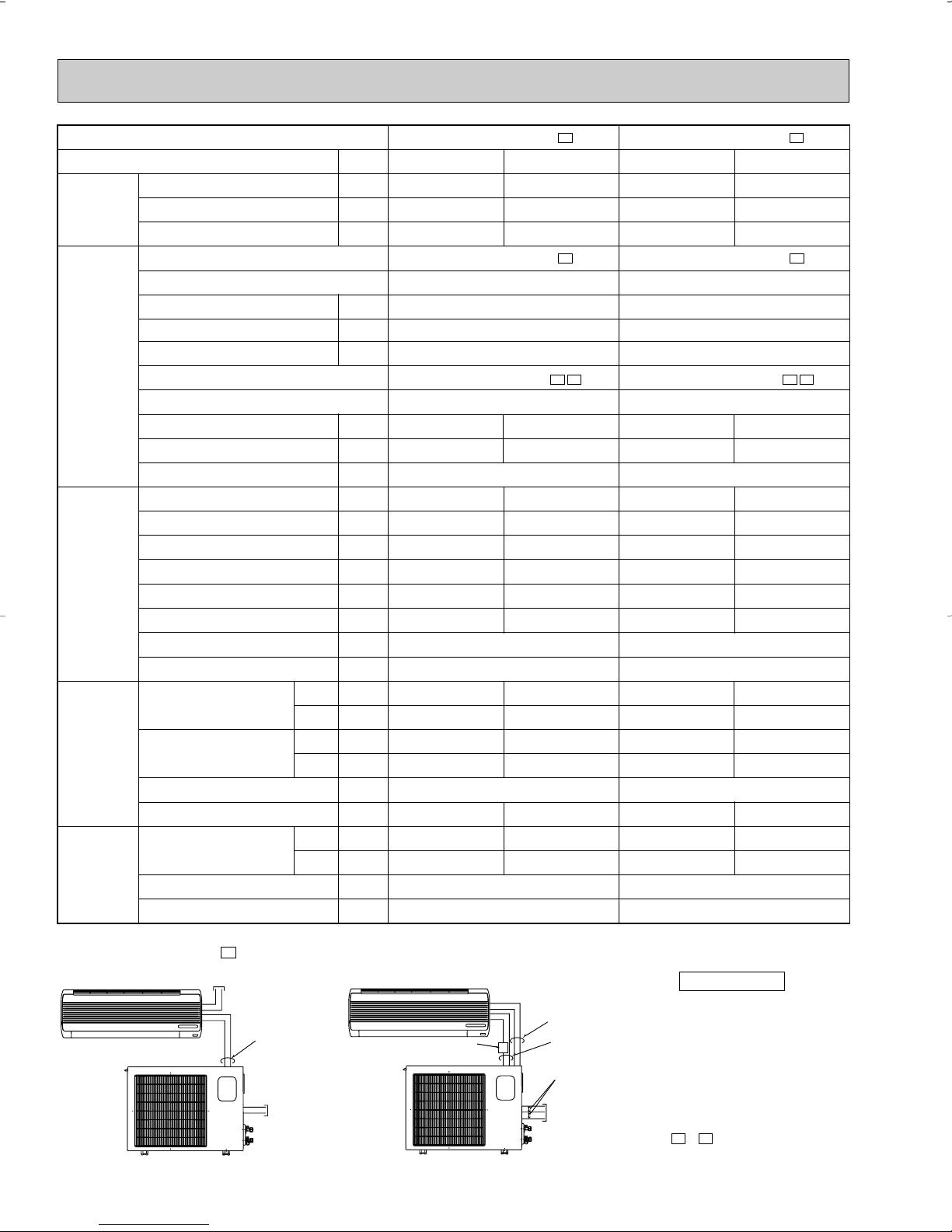
MSH12/15TN MSH12/15TN - U1
INDOOR UNIT
OUTDOOR UNIT
115V 60Hz 1[, 2wires
208/230V 60Hz 1[,
2 wires
SIGNAL WIRE
2 wires 12V DC
INDOOR UNIT
OUTDOOR UNIT
208/230V 60Hz 1[,
3 wires
115V 60Hz 1[,
2 wires
SIGNAL WIRE
2 wires 12V DC
•Both wirings can be applied to all MODELS.
115V
•Outline of MUH12TN( )
is same as one of MUH09TW.
- U1 , - U2
Disconnect
switch
POWER SUPPLY
28
✻ Control voltage
Power supply voltage to serial
signal circuit is 12V DC.
Peak voltage between 11and 33+ on in-out terminal
block is 12V DC .
Model
MSH17TN MSH17TN - U1
INDOOR UNIT
OUTDOOR UNIT
115V 60Hz 1[, 2 wires
208/230V 60Hz 1[,
2 wires
SIGNAL WIRE
2 wires 12V DC
INDOOR UNIT
OUTDOOR UNIT
208/230V 60Hz 1[,
3 wires
115V 60Hz 1[,
2wires
SIGNAL WIRE
2 wires 12V DC
•Both wirings can be applied to all MODELS.
115V
Disconnect switch
Item
Capacity (208/230V)
Total
Electrical
circuit
Refrigerant
circuit
SHF
Input (208/230V)
Indoor unit
Power supply (V, phase, Hz)
Input
Fan motor current
Aux. heater current
Outdoor unit
Power supply (V, phase, Hz)
Input (208/230V)
Comp. current (208/230V)
Fan motor current
Condensing pressure
Suction pressure
Discharge temperature
Condensing temperature
Suction temperature
Comp. shell bottom temp
Ref. pipe length
Refrigerant charge (R22)
Intake air temperature
Indoor
unit
Outdoor
unit
Discharge air temperature
Fan speed (High)
Airflow (High)
Intake air temperature
Fan speed (208/230V)
Airflow (208/230V)
POWER SUPPLY
Unit
Btu / h
—
kW
kW
A
A
kW
A
A
PSIG
PSIG
˚F
˚F
˚F
˚F
ft.
—
DB
WB
DB
WB
DB
WB
˚F
˚F
˚F
˚F
rpm
CFM
˚F
˚F
rpm
CFM
Cooling
16,000/16,200
0.64
1.56/1.58
1.506/1.526
6.69/6.19
243
77
165
113
48
150
80
67
56
54
413[Wet]
95
–
MSH17TN MSH17TN -
MSH17TN MSH17TN -
115,1,60
0.054
0.47
–
MUH17TN MUH17TN -
208/230, 1, 60
0.61
25
4 lb. 14 oz.
1,290
740/800
1,606/1,730
✻ Control voltage
Power supply voltage to serial
signal circuit is 12V DC.
Peak voltage between 11and 33+ on in-out terminal
block is 12V DC .
U1
Heating
16,800/17,200
–
1.50/1.57
U1
U1
1.446/1.516
6.39/6.09
242
63
162
112
35
144
70
60
109
–
491[Dry]
47
43
29
Capacity
SHF
Input
Outdoor unit
Power supply (V, phase, Hz)
Input
Comp. current
Fan motor current
Condensing pressure
Suction pressure
Discharge temperature
Condensing temperature
Suction temperature
Comp. shell bottom temp
Ref. pipe length
[Total pipe length for multi-system]
Refrigerant charge (R22)
Intake air temperature
Fan speed (208/230V)
Airflow (208/230V)
Unit
Btu / h
—
kW
kW
A
A
PSIG
PSIG
˚F
˚F
˚F
˚F
ft.
—
˚F
˚F
rpm
CFM
Heating
28,600
–
2.8
2.8
12.3
219
47
169
26
144
47
43
DB
WB
Item
Model
Total
Electrical
circuit
Refrigerant
circuit
Outdoor
unit
Cooling
28,400
–
3.8
3.8
17.1
300
65
194
41
150
95
–
MXZ30TN MXZ30TN2
208/230, 1, 60
0.60
127
82 [197]
8 lb. 10 oz.
630/675
1,764/1,906
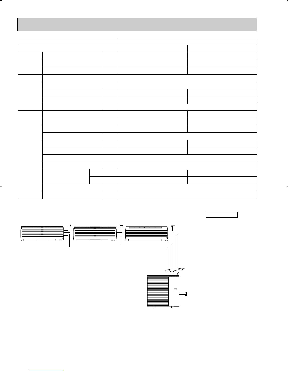
MXZ30TN MXZ30TN2
INDOOR UNIT
MXZ30TN
MXZ30TN2
115V 60Hz
1[, 2 wires
208/230V 60Hz 1[,
2 wires
SIGNAL WIRE
2 wires 12V DC
INDOOR UNIT
INDOOR UNIT
115V 60Hz
1[, 2 wires
115V 60Hz
1[, 2 wires
POWER SUPPLY
30
✻ Control voltage
Power supply voltage to serial
signal circuit is 12V DC.
Peak voltage between 11and 33+ on in-out terminal
block is 12V DC .
 Loading...