

Mitsubishi MOTORS M.U.T.-III Owner's Manual

M.U.T.-
III Owner’s Manual
Multi Use Tester
< Ver. 20.0 >
MITSUBISHI MOTORS

Foreword
This manual explains M.U.T.-III: functions, operating procedures, and other related information.
By reading this manual you will obtain a basic understanding of M.U.T.-III and Vehicle
Communication Interface (hereafter abbreviated as V.C.I.) functions and methods of operation.
Because there are differences in M.U.T.-III methods of operation due to the vehicle electronic
control system, be sure to read this manual and Online Help prior to operation.
This manual was written based on the Dec. 2010 version of the M.U.T.-III system.
Please note that the information herein may not always agree with your version of the M.U.T.-III
system due to system specification changes and version upgrades.
Please take good care of this manual along with your M.U.T.-III product.
M.U.T.-III Owner's Manual

Table of Contents
Chapter 1 Product Overview........................................................................................ 1
1-1. Precautions...............................................................................................................................1
1-2. V.C.I. Outline Drawing and Component Names........................................................................2
1-3. M.U.T.-III Components Explanations ........................................................................................3
1-4. Harness Connection Method ....................................................................................................5
1-5. Combination Chart of Harness and Vehicle..............................................................................6
Chapter 2 M.U.T.-III Functions...................................................................................... 8
2-1. Basic Functions ........................................................................................................................8
2-2. V.C.I. Functions ........................................................................................................................9
Chapter 3 Operating M.U.T.-III .....................................................................................11
3-1. Starting and Shutting the M.U.T.-III System ...........................................................................11
3-2. Screen Explanations...............................................................................................................13
3-3. Basic Flow to Start Diagnosis .................................................................................................15
3-4. Option Settings .......................................................................................................................19
3-5. Useful Functions.....................................................................................................................20
Chapter 4 Diagnosis Function ................................................................................... 21
4-1. Diagnostic Trouble Code ........................................................................................................21
4-2. Data List (Service Data monitor).............................................................................................24
4-3. Actuator Test...........................................................................................................................27
4-4. V.C.I. Stand-alone Diagnosis ..................................................................................................30
4-5. All DTCs..................................................................................................................................35
Chapter 5 Special Function (Calibration & Setting)................................................. 38
5-1. ECU Information .....................................................................................................................38
5-2. Learned Value Reset ..............................................................................................................38
5-3. Steering Angle Sensor Calibration ..........................................................................................39
5-4. Lateral G Sensor Calibration ..................................................................................................41
Chapter 6 Drive Recorder........................................................................................... 42
6-1. How to Record the Data .........................................................................................................42
6-2. Recorded Data Handling ........................................................................................................54
6-3. Display and Analysis of the Recorded Data............................................................................59
Chapter 7 SWS Monitor .............................................................................................. 65
7-1. SWS Monitor Operation..........................................................................................................65
Chapter 8 CAN Bus Diagnosis................................................................................... 74
8-1. Diagnosing the CAN Bus ........................................................................................................74
M.U.T.-III Owner's Manual

Chapter 9 ECU Reprogramming ................................................................................ 75
9-1. Process Flow Chart ................................................................................................................75
9-2. Equipments.............................................................................................................................76
9-3. Data preparation on PC from Update CD-ROM...................................................................... 77
9-4. Reprogramming Operation ( V.C.I. alone )..............................................................................79
9-5. Reprogramming Operation ( V.C.I. - PC connected ).............................................................. 86
9-6. Reprogramming by CAN communication................................................................................90
9-7. Troubleshooting of Reprogramming........................................................................................93
Chapter 10 Computer Diagnosis ............................................................................... 94
10-1. Operation method of MiEV Computer Diagnosis .................................................................. 94
Chapter 11 Measurement Functions ....................................................................... 100
11-1. Injector-Type Fuel Consumption Measurement ..................................................................100
11-2. Electricity Consumption Measurement................................................................................102
11-3. Fuel pressure, Voltage, Ohmmeter, Oscilloscope ...............................................................106
Chapter 12 How to Use (Special Case) ................................................................... 109
12-1. Copy Coding.......................................................................................................................109
12-2. Chassis No. / VIN Writing and Chassis No. / VIN Information ............................................ 110
12-3. Coding Operation................................................................................................................ 114
12-4. Customization Operation .................................................................................................... 118
Chapter 13 Troubleshooting Procedures................................................................ 121
13-1. Individual Troubleshooting Procedures...............................................................................121
13-2. Troubleshooting Procedures on V.C.I. Firmware Update ....................................................123
13-3. Troubleshooting of V.C.I. Stand-alone Diagnosis................................................................126
13-4. Troubleshooting of Reprogramming....................................................................................127
Chapter 14 Reference Material ................................................................................ 131
14-1. V.C.I. Electrical Properties ..................................................................................................131
Appendix ................................................................................................................... 132
<< Terminology >> .......................................................................................................................132
<< Screen Button Explanations >> ..............................................................................................134
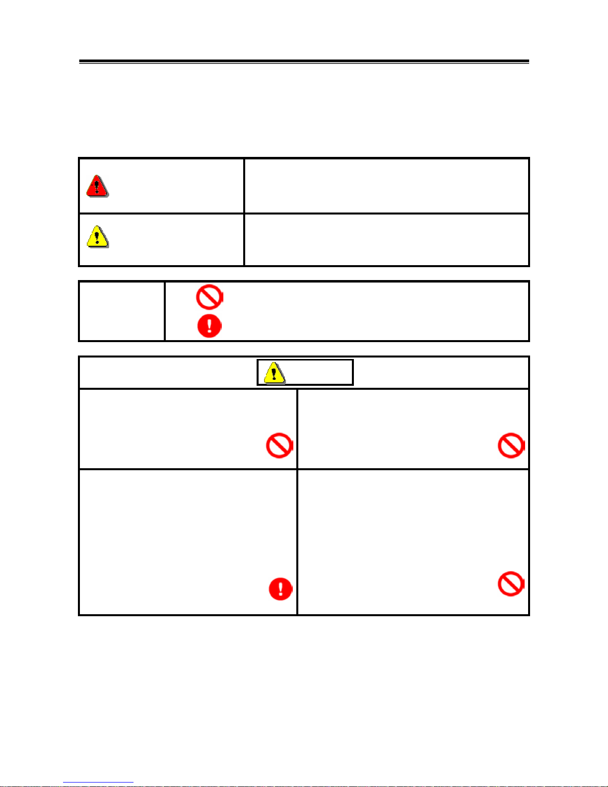
For Your Safety
To ensure proper use of this product and prevent personal injury and property damage, various graphic
displays are used in the user’s manual. The graphic displays and respective meanings are described
below.
Warning
Warning messages alert you to a procedure or practice
which, if not followed correctly, could lead to death or serious
injury.
Caution
Caution messages alert you to a procedure or practice
which, if not followed correctly, could lead to serious injury
and/or property damage.
Icon
Examples
The symbol alerts you to a prohibited action.
The symbol alerts you to an action that must be enforced.
Drivers should not operate the unit while
driving.
• Operating the unit while driving may result in
a traffic accident.
Do not plug in or unplug the power AC adapter
with wet hands.
• Doing so results in the risk of electric shock.
When using the cigarette lighter plug to supply
power to the V.C.I. unit, be sure the power
voltage supplied is DC32V or less.
• Applying a voltage greater than DC32V
results in the risk of fire.
• M.U.T.-III as provided to dealers includes
12V accessory / cigarette lighter plug
adapter to power M.U.T.-III during extended
test drives.
Maximum voltage the V.C.I. can withstand is 40V.
Do not use the V.C.I. on systems greater than the
32-volt system mentioned previously.
• Violating this requirement results in the risk of a
ground fault, damage and/or electric shock.
For Your Safety
Warning
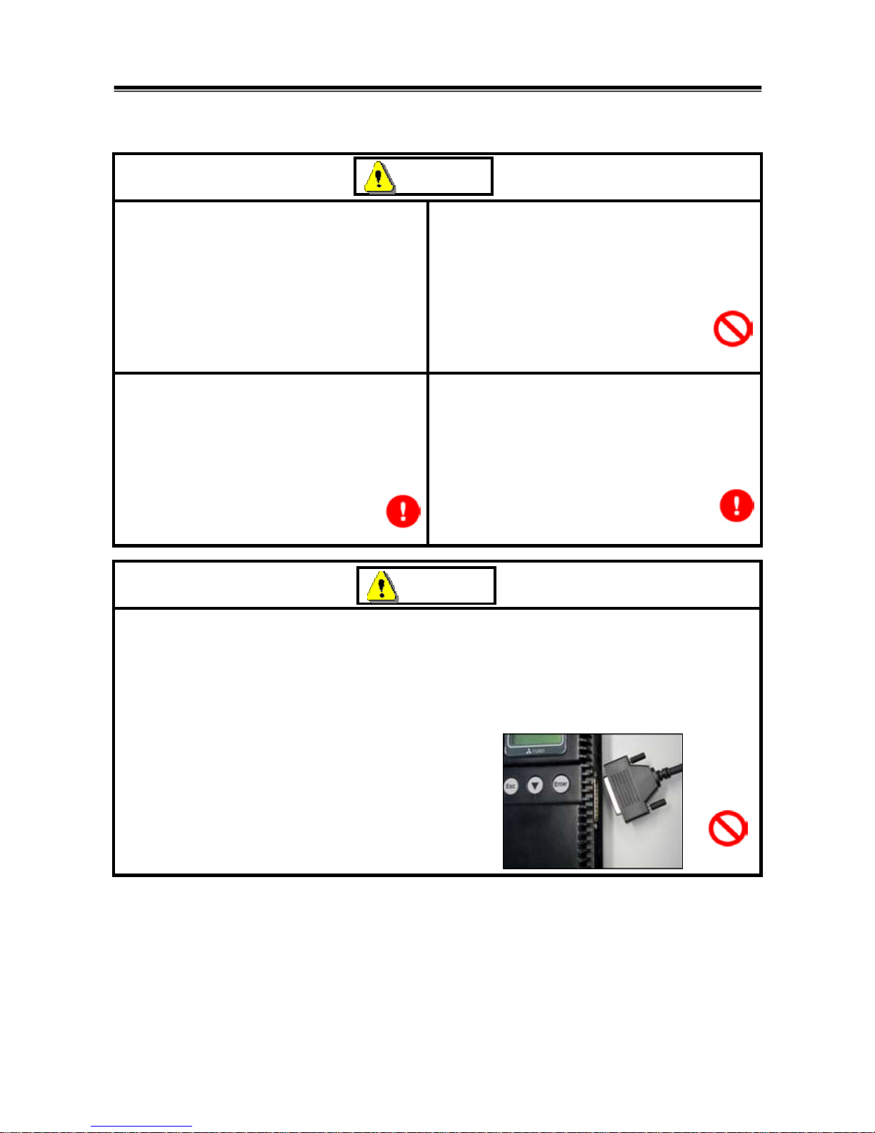
The V.C.I. screen is liquid crystal display or
LCD. In the unlikely event that the display
breaks due to impact, do not let your skin
come in contact with the LCD fluid.
• If your skin comes in contact with the LCD
fluid, wash your skin thoroughly with water.
If skin rash or abnormality occurs seek
medical attention from a doctor.
Do not use the unit if the power AC adapter plug
or cord is damaged or plugging into the outlet is
loose.
• Use under such conditions may result in
electric shock, an electric short and/or fire.
Be sure to hold the harness connector when
disconnecting from the vehicle. Do not
disconnect the harness by pulling on the cord.
• Pulling the cord rather than the connector
may result in damage to the lead wire inside
the cord, thereby causing a short and
possibly starting a fire.
Unplug the power AC adapter from the outlet
when the unit is not in use.
• Failure to do so may result in injury, burns,
electric shock caused by insulation
deterioration, or fire due to a short circuit.
When the harness is connected to the V.C.I., be sure to check the top and bottom of the
connector and connect the harness perpendicularly to the connector of the V.C.I.
Connecting at an angle may result in bending of the pins of the connector.
Check for the secure connection of the harness before tightening of the screw locks.
• The bent pin may contact the connector case, thereby causing an electric short which
leads to damage to the V.C.I.
Warning
Warning
For Your Safety

Please Note
Do not expose the PC or V.C.I. to direct sunlight or high temperatures, or leave the unit in
sun-heated cars. Such action may result in system failure.
Store the PC and V.C.I. in a dry environment at room temperatures.
Moving the PC and V.C.I. to a location with a very different temperature and humidity than that of
the previous location may result in external or internal condensation. Caution is required.
Protect the PC and V.C.I. from exposure to elements such as rain, dirt, dust, food and liquids.
Be careful when handling the PC and V.C.I. Dropping the units may result in damage.
Do not expose either unit to engine oil, gasoline, antifreeze or battery acid. Also, do not clean the
PC or V.C.I. case using solutions such as thinner or benzene. Doing so may result in deterioration
of the case surface.
Prior to connecting the M.U.T.-III main harness between the V.C.I. and vehicle, turn the IG switch
to OFF.
• Connecting the V.C.I. harness with the IG switch ON may damage the V.C.I. programming.
Use only the power AC adapter included with the PC (or approved replacement), power cigarette
plug, other probes, main harness and other cables.
• Use of unspecified parts may result in damage or malfunction due to excess voltage or
insufficient contact.
The LCD display of this unit turns off when the supplied voltage is less the DC 8V. This is not an
error.
The power supplied should be from 8VDC to 32VDC.
Keep all V.C.I. connectors and openings away from dirt and static electricity. Exposure to dirt and
static electricity may result in malfunction and damage.
For Your Safety
1
Chapter 1 Product Overview
1-1. Precautions
Service Work Precautions
• Be sure to follow all basic service work precautions when using M.U.T.-III during vehicle
inspection and service work.
• For detailed information regarding service work precautions, refer to the service instruction
manual of each vehicle.
Work Precautions
• When performing vehicle inspection work at the work site with the engine running, either use an
exhaust gas discharger or ventilate the area sufficiently.
• When working on a vehicle, be sure to apply the parking brake and set wheel chocks in place to
prevent the car from moving.
Driving Precautions
• If you wish to use M.U.T.-III while driving the target vehicle, first verify that all parts are properly
assembled.
• While driving, always have an assistant operate M.U.T.-III.
• Be sure that the M.U.T.-III main harness and other cables will not interfere with driving.
• Install and remove the PC and V.C.I. with the vehicle parked, IG switch OFF.
PC Usage Limitations
Do Not Install Software on the PC
• The M.U.T.-III PC is a special service tool. Do not install any software other than M.U.T.-III
software onto the unit. Installation of other software results in the risk of M.U.T.-III system
failure.
• Any unauthorized software will not be supported. Technical support for units with
unauthorized software will be charged additional technical support fees to return the unit to its
authorized state of operation.
• All unauthorized software will be erased with each new upgrade.
Precautions
2
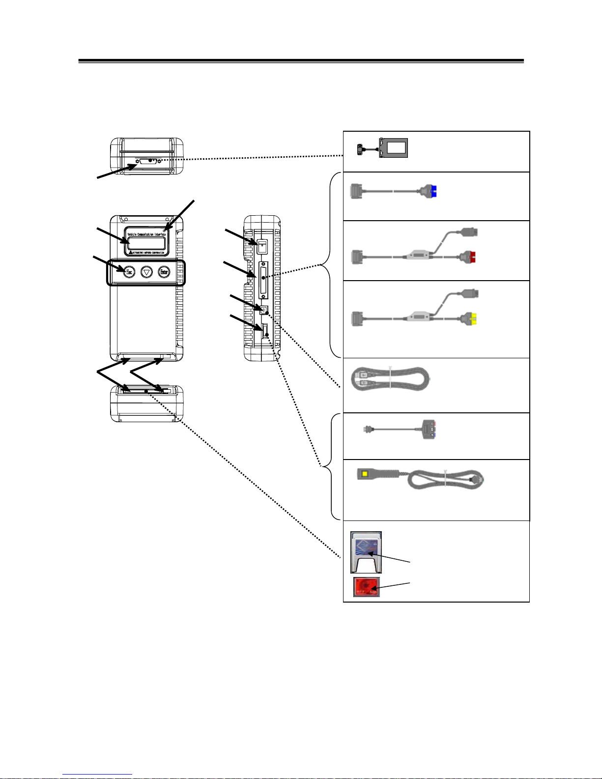
1-2. V.C.I. Outline Drawing and Component Names
The names of the V.C.I. components are indicated in the figure below.
<<Component Names>>
1. I/F cartridge terminal
2. LCD screen
3. Indicator lamp
4. Operation button
(Used with V.C.I. functions)
5. Memory card removal lever
6. Memory card insertion port
7. Power switch
8. Main harness terminal
9. USB terminal
10. Trigger terminal
V.C.I. Outline Drawing and Component Names
Trigger harness (MB991826)
(Not available in US)
CF memory card
& adapter
(MB991853, MB992228)
(MB991939)
I/F cartridges
M.U.T.-III main harness A (MB991910)
M.U.T.-III main harness B (MB991911)
USB cable (MB991827)
Measurement adapter (MB991825)
6
1
8
9
10
3
4
5
2
7
M.U.T.-III main harness C (MB991914)
(For US only)
3
1-3. M.U.T.-III Components Explanations
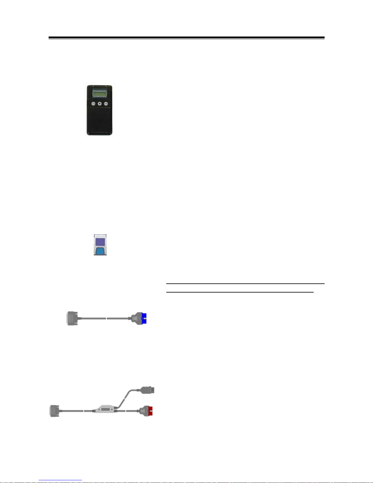
(1) Vehicle Communication Interface (V.C.I.) (MB991824)
A communication interface used to connect the vehicle
ECUs and the PC.
1. When connected with the PC
• Vehicle diagnosis (Interactive fault diagnosis)
• SWS communication & CAN communication support
• Drive recorder
• ECU reprogramming
• Volt, Ohm, measurement
• Fuel pressure measurement (Not available in US)
2. When used with the V.C.I. unit (disconnected from PC)
• V.C.I. Stand-alone diagnosis
• Drive recorder
• ECU reprogramming
• Volt, Ohm measurement
• Belt Tension measurement
(2) Memory Card
Stores data for ECU reprogramming, drive recorder, etc.
This is a standard, off-the-shelf memory card. The one
provided (with reprogramming data) is a Compact Flash
memory card (MB991853, MB992228) inserted into the CF
card adapter (MB991939).
It is necessary to initialize a Compact Flash memory card
by FAT16 and FAT32 format. (NTFS format cannot use)
(3) M.U.T.-III Main Harness A (MB991910)
Used when connecting the V.C.I. with vehicles that have
only one 16-pin diagnosis connector.
• Supports fault diagnosis and ECU updating on the
above-described vehicles
• Supports the CAN communication system
(4) M.U.T.-III Main Harness B (MB991911)
Used when connecting V.C.I. with vehicles that have a
16-pin + 12-pin or 16-pin + 13-pin diagnosis connector.
For models equipped with only 12-pin (or 12-pin + 12-pin)
diagnosis connector, connect the M.U.T.-II adapter harness
(MB991498) to the end of this harness in the same as
M.U.T.-II, and power is supplied from the cigarette lighter
socket.
M.U.T.-III Components Explanations

4
(5) M.U.T.-III Main Harness C (MB991914) (For US only)
Used when connecting the V.C.I. with vehicles that have the
420A engine and F4AC1 transaxle.
(6) USB Cable (MB991827)
Used to connect the PC to the V.C.I.
(7) Trigger Harness (MB991826) (Not available in US)
A harness with a trigger button used to manually insert a
trigger point for data acquisition from the drive recorder
function during data recording.
(8) Measurement Adapter (MB991825)
An adapter used to connect the V.C.I. and measurement
probe for voltmeter and ohmmeter readings.
Or used when outputting Simulated Vehicle Speed with a
vehicle whose diagnosis-connecter cannot receive vehicle
speed signal.
(9) Measurement Test Leads (MB991499)
Test leads used for voltage and / or resistance
measurement.
Test leads MB991499 acquire quality replacement test
leads from Radio Shack or similar electronics stores.
(10) I/F Cartridge
Used to implement special functions that cannot be
implemented with the V.C.I. unit alone. The following I/F
cartridges used with M.U.T.-II can be used with M.U.T.-III as
well:
• SWS monitor cartridge (MB991806)
• Tension meter cartridge (MB991669)
• Daimler-Chrysler Corporate I/F cartridge (MB991544)
(For US Only)
M.U.T.-III Components Explanations
5
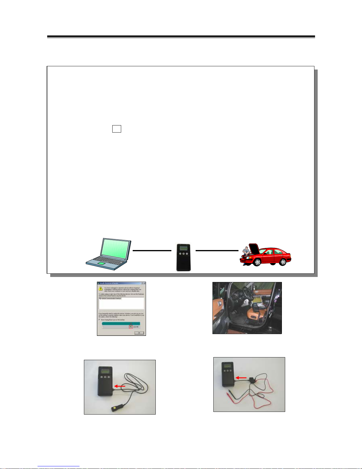
1-4. Harness Connection Method
Harness Connection Method
Recommended harness connection sequence
[1] Start the PC.
[2] While the PC is starting, connect the USB cable to the V.C.I.
[3] After the PC boots to the M.U.T.-III main screen, connect the USB cable to the PC.
Note: Disconnect the USB cable from the V.C.I. after the PC has shut down. However, if the
USB cable is disconnected during use, a warning message indicating device
disconnection such as that shown in Figure 1 appears. Close the message display by
pressing the OK button.
[4] Select the appropriate M.U.T.-III main harness. Connect it to the V.C.I.
[5] Connect the M.U.T.-III main harness to the vehicle diagnosis connector. See Figure 2.
Note: Disconnect the harnesses by performing the above steps in the reverse order.
[6] Turn the V.C.I. power switch ON and verify that the indicator lamp located in the upper right area
of the LCD screen is green.
[7] Turn the vehicle ignition switch ON, and begin the diagnostic process from the M.U.T.-III system
screen.
Note: In case the version of V.C.I. and the firmware version of V.C.I., which are mismatch, a
dialog box appears on PC screen, and the V.C.I. version upgrade process begins. This
upgrade typically only occurs once per M.U.T.-III system upgrade. Normal V.C.I.
upgrades take about 1 minute. If a version upgrade error occurs, restart the V.C.I. by
turning V.C.I. power OFF then, while pressing the Esc button, turn the V.C.I. power switch
ON and begin the diagnostic process again.
[5][2][3] [4]
[6]
[7]
[1]
Connect the trigger harness to the
V.C.I. trigger terminal.
(Not available in US)
<Connecting the Trigger Harness>
Connect the measurement adapter to the V.C.I.
trigger terminal. Insert the measurement leads to
the adapter. For best results, match the test lead
colors with those on the adapter.
<Connecting the Measurement Adapter
and Measurement Probe>
<Fig. 2>
<Fig. 1>
6
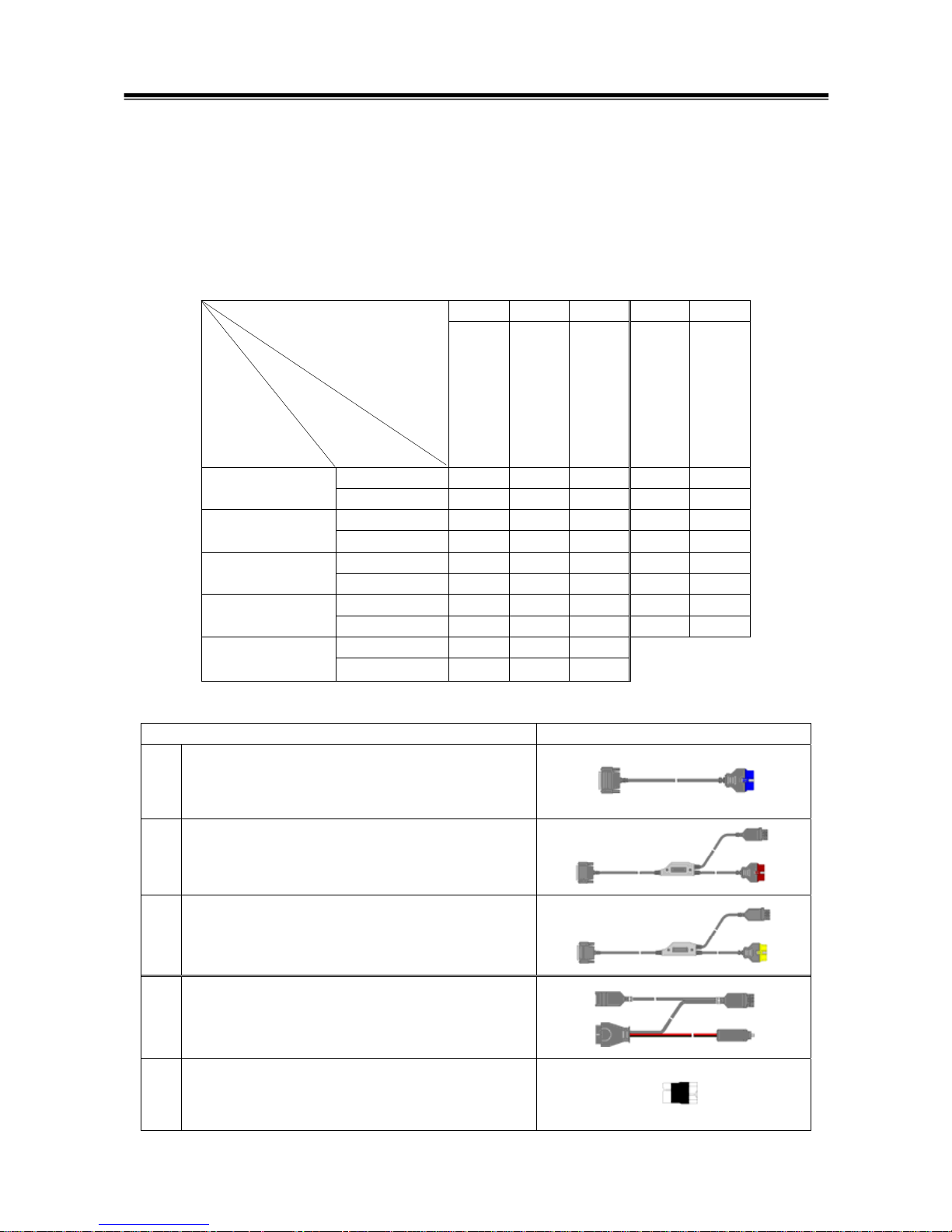
1-5. Combination Chart of Harness and Vehicle
Use of the M.U.T.-III main harness A, B or C (US only) is determined by the type of diagnosis
connector installed in the vehicle.
The main harness, indicated with “O”, is used in combination with another harness indicated with
“z” depending on the vehicle and work to be performed. ECU update used below means ECU
reprogramming.
01 02 03 04 05
Harness Name
Vehicle
Diagnosis
Connector
M.U.T.-III Main
Harness A
M.U.T.-III Main
Harness B
M.U.T.-III Main
Harness C
Conventional
Vehicle Inspection
Adapter Harness
ECU Update
Adapter Harness
Fault diagnosis O
16Pin
ECU update O
Fault diagnosis O
16Pin&12Pin
ECU update O
Fault diagnosis O z
12Pin
ECU update - - - - Fault diagnosis O
16Pin&13Pin
ECU update O z
Fault diagnosis O
Vehicle with
420A Engine and
F4AC1 Transaxle
ECU update -
-
-
Harness Name Illustration
01 M.U.T.-III Main Harness A
MB991910
02 M.U.T.-III Main Harness B
MB991911
03 M.U.T.-III Main Harness C
MB991914
(For US only)
04 Conventional Vehicle Inspection Adapter Harness
(M.U.T.-II adapter harness)
MB991498
05 ECU Update Adapter Harness
MB991855
Combination Chart of Harness and Vehicle
Diagnostic
Function
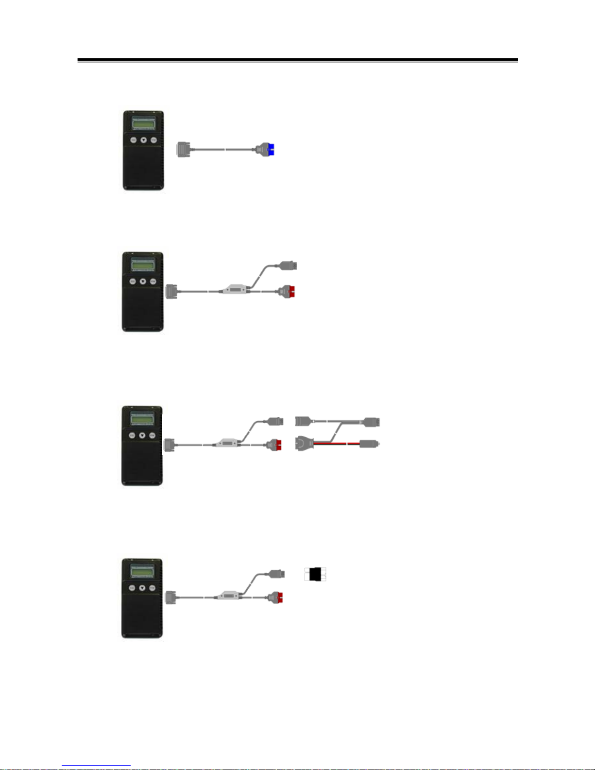
7
Vehicle diagnostic connector - 16pin type
to 16pin diagnosis connector
Vehicle diagnostic connector - 16pin type + 12 pin type
to 12pin diagnosis connector
to 16pin diagnosis connector
Vehicle diagnostic connector - 12pin type
to 12pin diagnosis connector
to cigarette lighter
Vehicle diagnostic connector - 16pin type + 13 pin type
to 13pin diagnosis connector
to 16pin diagnosis connector
Main harness A
(MB991910)
Main harness B
(MB991911)
Main harness B
(MB991911)
Main harness B
(MB991911)
Conventional Vehicle Inspection Adapter harness
(M.U.T.-II Adapter Harness)
(MB991498)
ECU update
adapter harness
(MB991855)
Combination Chart of Harness and Vehicle

8
Chapter 2 M.U.T.-III Functions
2-1. Basic Functions
Can be used with all vehicle installed electronic control systems (with built-in diagnostic functions)
from model year 1984.
Function
Synopsis
DTC readout
Reads various diagnostic codes and displays the codes by name and
number.
Data List
Reads RAM data inside ECU and displays the data in digital and graphic
form. (Available with ECUs that support serial communication only)
Actuator tests
Permits forced operation or shutdown of various types of actuators that is
required for service.
(Available with ECUs that support serial communication only)
Simulated
vehicle speed
Outputs vehicle speed signal to appropriate ECUs facilitating diagnosis
without travel.
Drive Recorder
Permits recording and displaying arbitrary service data that is determined
for an arbitrarily specified time.
Voltmeter
Permits measurement of DC voltage within the range of 0- ±40V using
the voltage measurement function.
Ohmmeter
Permits measurement of resistance within the range of 0-100KΩ using
the resistance measurement function.
SWS Diagnosis
Permits SWS diagnosis using the SWS monitor kit (MB991806).
CAN Bus Diagnosis
Identifies CAN bus failures that occur in vehicle that is subject to the
diagnosis and narrows down a cause.
ECU Reprogramming
Permits updating programs in ECU for system version upgrade.
Electronic service
information
Displays with Service manual data.
In addition, the system supports interactive fault diagnosis. The Interactive
Diagnosis permits user to use both the scan tool viewing functions and
service manual troubleshooting procedures.
(Not available in US)
Tension meter
Permits measurement of belt tension using Belt tension meter set
(MB991668). * Belt tension meter set had ended production.
Fuel pressure meter
Permits measurement of fuel pressure using a pressure gauge set
(MB991637 / MB991981), and displays it on PC. (Not available in US)
Fuel consumption
measurement
Permits more precise measurement of fuel consumption by measuring
injection quantity of fuel injector.
Basic Functions

9
2-2. V.C.I. Functions
<When V.C.I. and PC are connected>
2-2-1. Fault Diagnosis
The system diagnoses faults by receiving instructions from
the PC and communicating with the vehicle-installed ECU.
When the system is connected to the PC, V.C.I. keys are
disabled.
[Start Screen]
*When the USB cable is connected to the system, the
screen illustrated on the left appears.
The screen indicates the flow of signals between the PC (P)
and V.C.I. (V) using “P Æ V” and “P Å V”.
2-2-2. Fuel Pressure measurement (Not available in US)
The system analyzes faults by measuring fuel pressure
using the Pressure gauge set (MB991637 or MB991981).
Pressure gauge for LP: MB991655 or MB991979
for HP: MB991708 or MB992007
The V.C.I. reads the fuel pressure, which is converted into
voltage value by the pressure gauge. Then the system
converts it back to pressure value and displays it as text or
graph on PC screen. (refer to 11-3-1.)
<With the V.C.I. only>
2-2-3. Measurement Function - Voltmeter / Ohmmeter
The system reads the voltage/resistance value from the trigger
terminal and displays the value on the V.C.I. LCD screen.
1. Connect the measurement adapter to the V.C.I., connect the
test leads to the adapter.
2. Connect the appropriate main harness to the V.C.I., and then
to the vehicle diagnostic leak connector and turn the V.C.I.
power switch ON.
3. Press
button to select Voltmeter or Ohmmeter in the
Main Menu (see the illustration on the left), and press the
(Enter) button to begin measurement.
Note:
• Permits measurement of DC voltage within the range of 0-
±40V.
• Permits measurement of resistance within the range of
0-100KΩ.
• Permits displaying the value as text or graph on PC
screen by connecting the V.C.I. to PC. (refer to 11-3-2.)
V.C.I. Functions
10
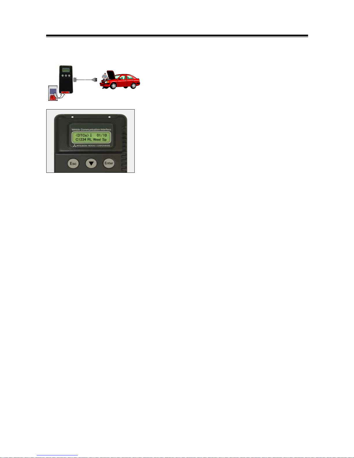
2-2-4. V.C.I. Stand-alone Diagnosis
You can read out DTCs with V.C.I. stand-alone by using a
memory card, which is storing a diagnostic data transferred
from PC. There is no need to carry PC or USB cable on the
diagnosing vehicle. (For detailed operation, see 4-4)
1. Transfer the diagnostic database file into a memory card.
(4-4-1)
2. Insert the memory card into V.C.I., and then connects the
V.C.I. and the vehicle with an appropriate main harness.
3. Start reading out DTCs from vehicle-installed ECU by V.C.I.
stand-alone. (4-4-2)
Note:
Until a new database file will be distributed, you do not have to
operate above step1. Please proceed just step2 and 3.
V.C.I. Functions
11
Chapter 3 Operating M.U.T.-III
3-1. Starting and Shutting the M.U.T.-III System
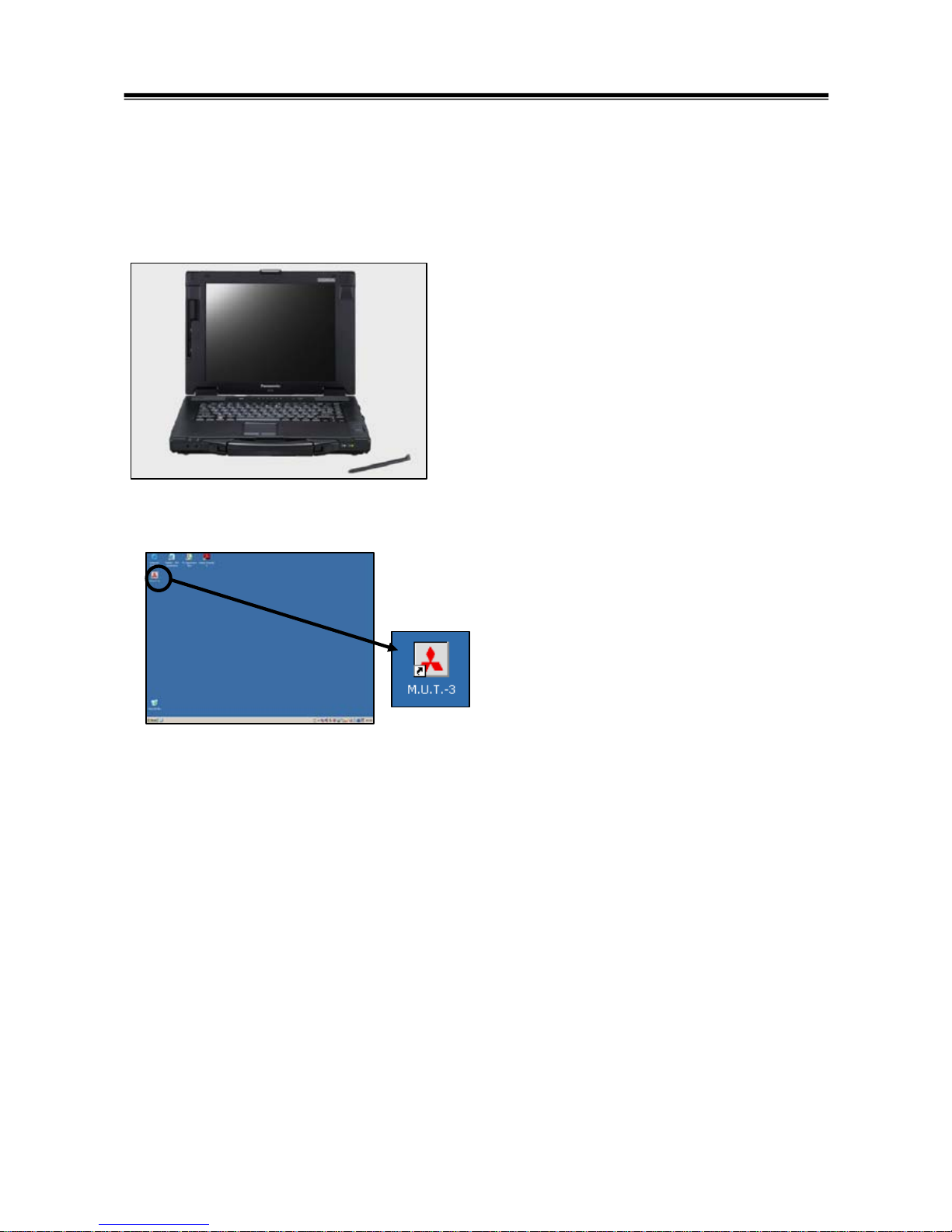
3-1-1. Starting the M.U.T.-III System
[Starting the PC]
1. Please turn on the power of M.U.T.-III PC.
(Refer to the instructions of M.U.T.-III PC for
details.)
[To start up M.U.T.-III System]
2. Double-click the M.U.T.-III icon displayed on the
desktop to start up the system.
Trademarks
• Microsoft®, Windows 2000®, Windows XP®, Windows Vista®, Windows 7® and Internet Explorer®
are trademarks or registered trademarks of Microsoft Corporation in the United States and/or other
countries.
• Adobe, the Adobe logo, and Reader are either registered trademarks or trademarks of Adobe
Systems Incorporated in the United States and/or other countries.
Starting and Shutting the M.U.T.-III System
[M.U.T.-III icon]
12
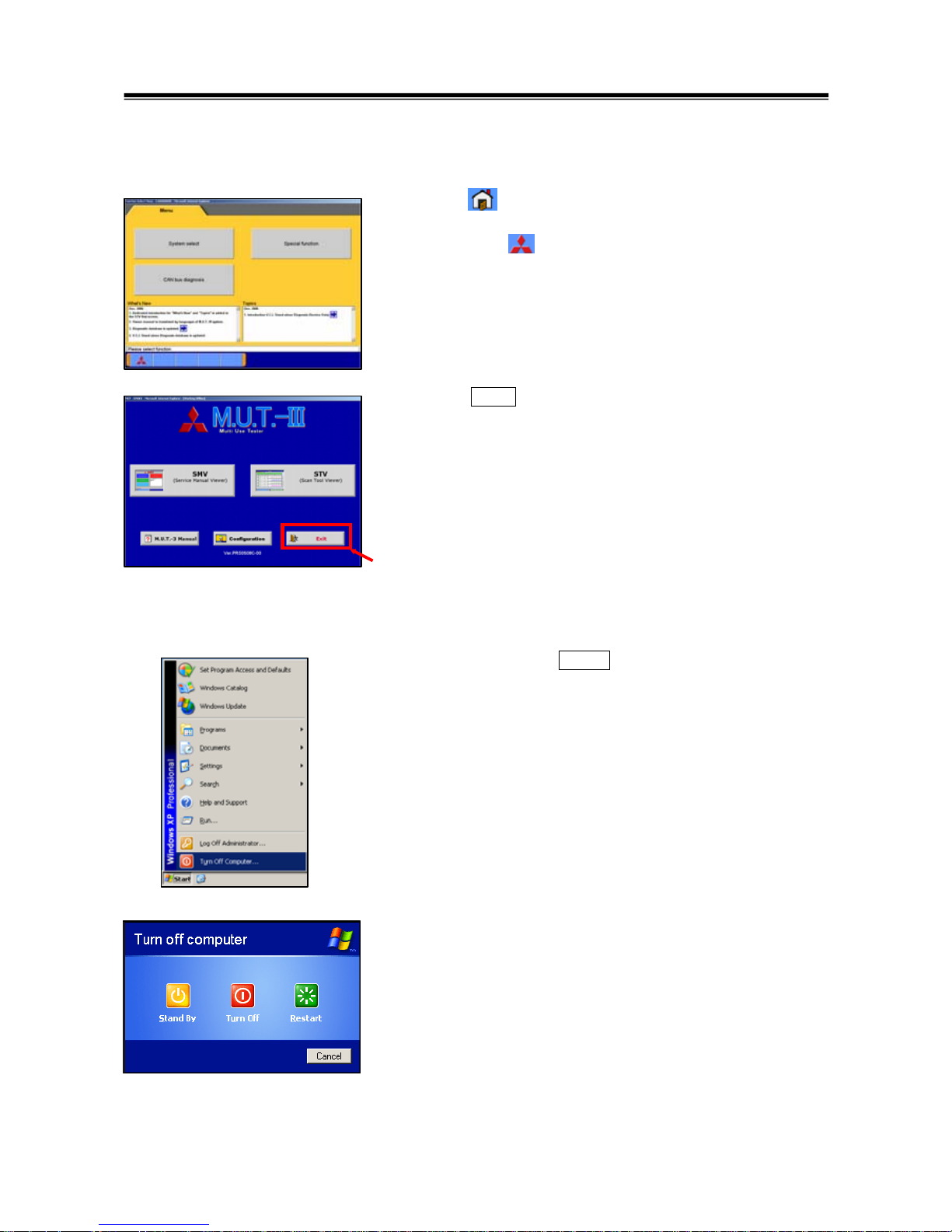
3-1-2. Shutting Down the M.U.T.-III System
[Close the M.U.T.-III System]
1. Press button on each diagnostic screen to return to the
STV Top Menu screen (illustrated on the left).
Then press button on this screen to go to the M.U.T.-III
Start screen.
2. Press Exit button displayed on the lower right portion of
the M.U.T.-III Start screen. M.U.T.-III system will close.
[Shutting down the PC]
3. Click the Windows Start button (lower left portion of the
screen), and select “Turn off Computer…”.
4. Select “Turn off” button.
Starting and Shutting the M.U.T.-III System
13
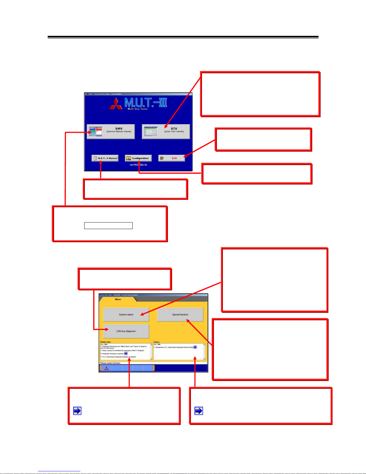
3-2. Screen Explanations
Screen Explanations
< M.U.T.-III Start Screen >
To set option settings, e.g. displaying
language. (refer to 3-4.)
Starts “Scan Tool Viewer (STV)” system.
This manual contains information for
proper operation of this system.
Press this button first to start various
interactive diagnoses.
Exits the M.U.T.-III system.
(refer to 3-1-2.)
Starts “Service Manual Viewer (SMV)”.
For detailed operation procedure,
click the SMV MANUAL bookmark
on the left screen of Adobe Reader.
Shows “M.U.T.-III Owner’s Manual”.
(refer to 3-5-2.)
< STV Top Menu >
-To display saved data
(Drive recorder, SWS monitor)
-V.C.I. Stand-alone Diagnosis (4-4)
-All DTCs Function (4-5)
-ECU reprogramming (Chapter 9)
-MiEV Computer Diagnosis (Chapter 10)
-Measurement Function (Chapter 11)
To diagnose vehicles by selecting
each system (ECU).
e.g.
-Reading diagnostic trouble code
-Actuator test -Drive recorder
For detailed operation procedure,
refer to 3-3-1.
Starts the CAN bus diagnosis.
refer to Chapter 8.
The items changed by this update are
being written in this window.
Clicking on this button more details
can be found.
The function to be mentioned or countermeasure
of FAQ is being written in this window.
Clicking on this button more details can be
found.

14
The Special Function selection screen
allows you to switch between major
categories by selecting the tabs
located on the upper part of the screen.
<Diagnostic Screen>
The diagnostic screen displays three
titles in layer format, informing you
what is being implemented on each
system. The screen does not allow
you to switch systems by selecting
the upper title areas.
Screen Explanations
This screen is for specifying a system that
you want to diagnose.
As operation procedure differs according
to the vehicle’s Model Year, please select
“Up to 2005MY”
(2004MY in EU) or “From
2006MY”
(2005MY in EU) firstly.
(refer to 3-3-1)
< System Selection Screen >
<Special Function Selection Screen>
15
3-3. Basic Flow to Start Diagnosis
3-3-1. Basic Flow of System Select Diagnosis
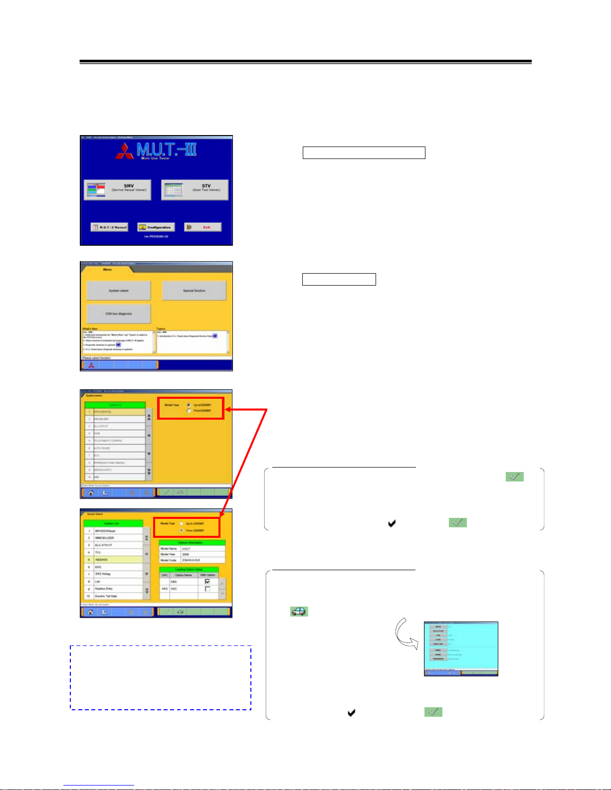
(1) M.U.T.-III Start Screen
Press
STV (Scan Tool Viewer) button on the M.U.T.-III
Start Screen.
(2) STV Top Menu
Press
System Select button on the STV Top Menu screen.
(3) System Selection Screen
Select either one of “Up to 2005MY” or “From 2006MY” for
the Model Year of the vehicle you are diagnosing.
Then follow the each operation below.
When selecting “Up to 2005 MY”
1. Select a system on the System List
(*a), and press .
2. If the system has a loading option, the Loading Option
Setup list
(*b) will be displayed. Then, select an item
having a box checked ( ) and press button.
When selecting “From 2006 MY”
1. Confirm the contents of the Vehicle Information list
(*c).
-When the contents are not describing the vehicle, press
to correct the information. (For details, refer to 3-3-2)
2. Select a system on the System List
(*a), and if the Loading
Option Setup list
(*b) is displayed, select an item having a
box checked ( ). Then press
button.
Basic Flow to Start Diagnosis
*a
*b
*c
*a
Note:
M.U.T.-III for EU countries, the options
for Model Year is classified in
“Up to 2004 MY” and “From 2005 MY”.
16
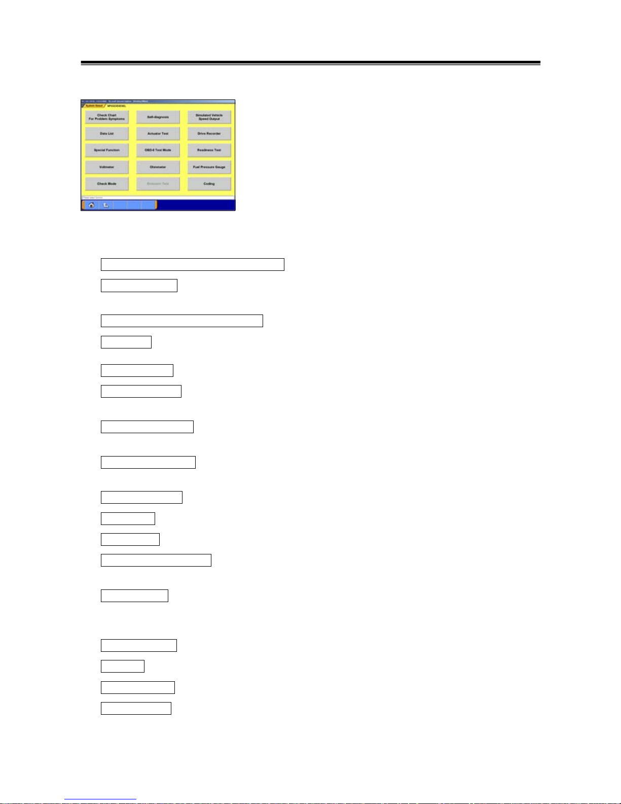
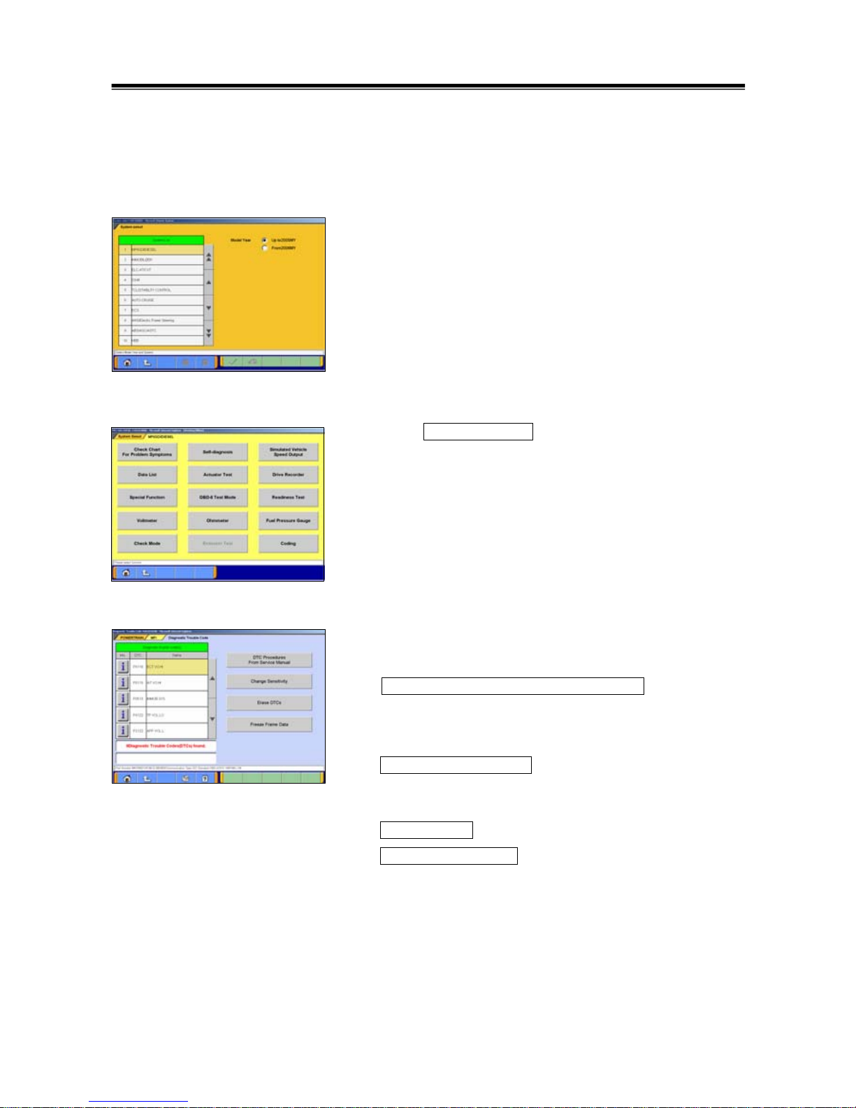
(4) Function Selection Screen
After System selection, the Function selection menu of the
selected system appears. Select a button that you want to
perform.
In the picture on the left shows the screen appears when the
MPI/GDI/DIESEL system, which is a representative example,
is selected. Details of each buttons are as follows.
Note:
As available functions differ between systems, there might be
functions that will not appear when you select other system.
Check Chart For Problem Symptoms -- To view the Symptom Chart of Service Manual.
Self-diagnosis
-- To read out or erase Diagnosis Trouble Codes from vehicle ECU.
Also, you can read out the Freeze Frame data. (refer to 4-1.)
Simulated Vehicle Speed Output --To transmit simulated vehicle speed signal into the vehicle.
Data List -- To read the RAM data inside the ECU and displays the data in digital and graphic form.
(refer to 4-2.)
Actuator Test -- To control the ECU output device. (refer to 4-3.)
Drive Recorder -- To record, display or analyze the ECU input / output signals which can be viewed
using Data List function. (refer to Chapter 6)
Special Function -- To execute special functions specific to the selected system. For detailed
operation other than Chapter 5, please utilize each Online Help function.
OBD-II Test Mode -- To read out “Monitoring test results” “Provisional DTC” and “ECU information”,
which are regarding Emission Related System, from ECU.
Readiness Test -- To read out the result of Readiness Test from ECU.
Voltm ete r -- To measure voltage value using M.U.T.-III. (same operation as 11-3-2)
Ohmmeter -- To measure resistance value using M.U.T.-III. (same operation as 11-3-2)
Fuel Pressure Gauge -- To measure fuel pressure using a pressure gauge, and display the result
on PC screen. (Not Available in US)
Check Mode – To shorten sampling time of communication by changing the communication method
between M.U.T.-III and ECU. This function is available in Data List, Drive Recorder,
Actuator Test and Special Function.
Emission Test -- To test the Evaporative Emission Control System of the vehicle.
Coding -- To write the vehicle equipment specifications into ECU.
SWS monitor (appears only when selecting “SWS” system) (refer to Chapter 7)
Pulse Check (appears only when selecting “SWS” system)
-- To confirm existence of the signal pulse to operate remote system on SWS
communication line.
Basic Flow to Start Diagnosis
[MPI/GDI/DIESEL ‘s Function Selection menu]
17
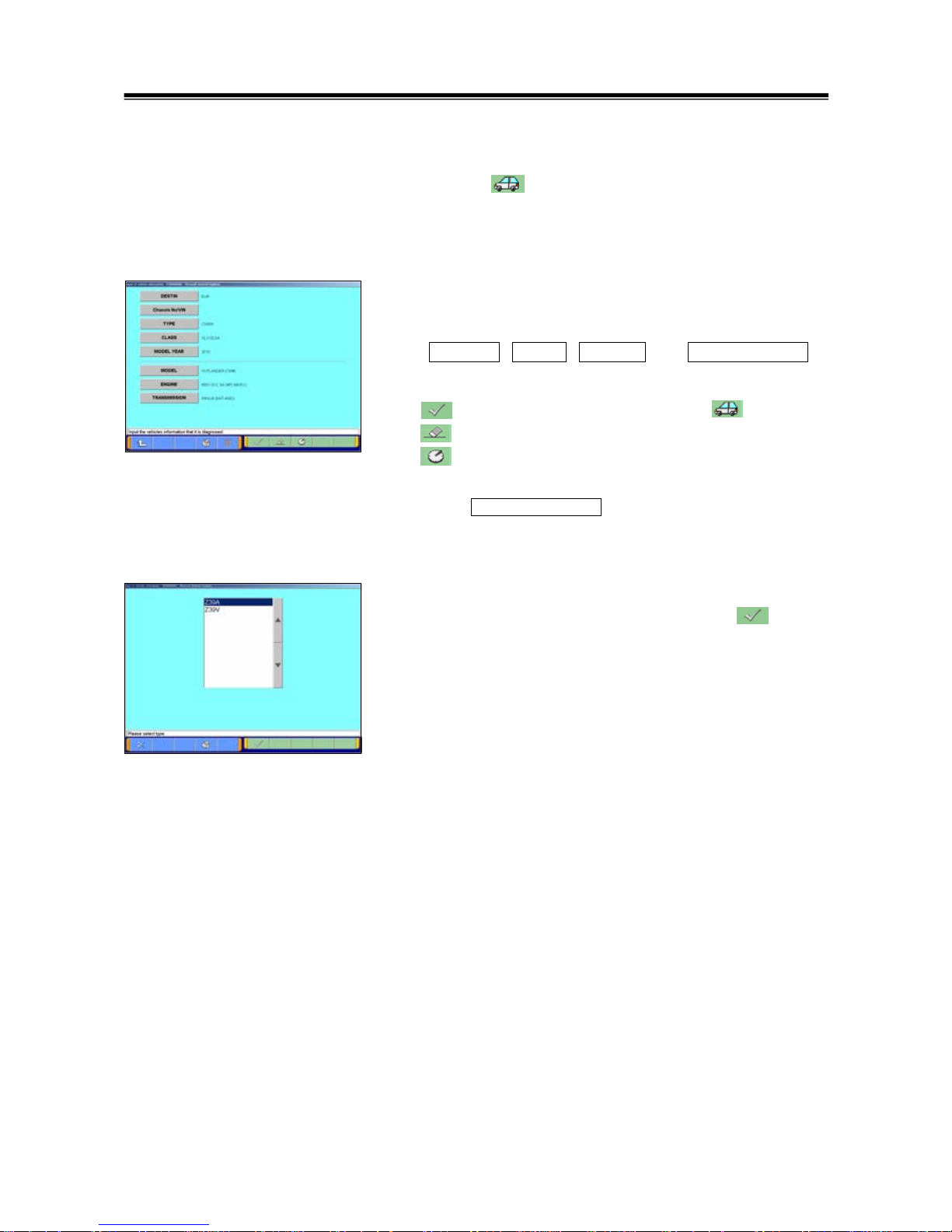
3-3-2. Vehicle Information Setting
Pressing button, on System Selection Screen or other
vehicle-confirmation screen, displays the Vehicle Information
Setting Screen. This screen allows you to modify the
diagnosing vehicle information.
(1) Vehicle Information Setting Screen
-Currently selected information is displayed in each item’s
field. (Blank space means the information is not selected.)
-
DESTIN , TYPE , CLASS and MODEL YEAR are
compulsory input.
--OK (Returns to the screen on which was pressed)
--Deletes whole information
--Displays history of settings as open options.
Press an item button to modify. -- to (2)
Press Chassis No/VIN button to modify. -- to 3-3-3.
(2) The item’s individual selection screen appears.
Apply appropriate information, then press button to
return to the Vehicle Information Setting screen (1).
Basic Flow to Start Diagnosis
18
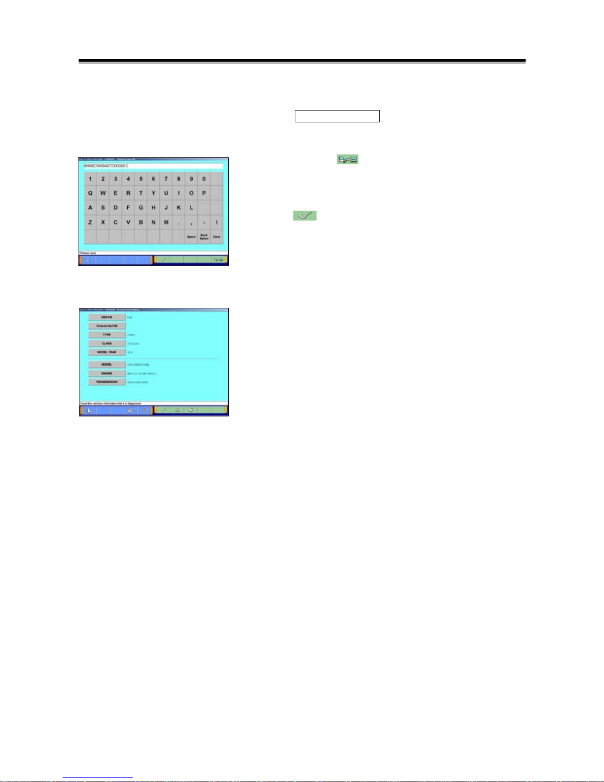
3-3-3. Function of vehicle recognition by Chassis No /VIN
Click Chassis No/VIN button in the Vehicle Information
setting screen.
When you click button, Chassis No/VIN is automatically
input into the column, but if any information would not be
responded, then you need to input Chassis No /VIN manually.
Click button after the input of Chassis No /VIN.
* The Chassis No/VIN can be read only a vehicle
corresponding to Engine-ECU which is adopted with CAN
communication.
The vehicle information with Chassis No/VIN is retrieved, and
the information is automatically input.
* The database for this retrieval function is at that time when
M.U.T.-III is released, for this reason vehicle information for
the later vehicles might not be able to be retrieved.
Basic Flow to Start Diagnosis
19
3-4. Option Settings
3-4-1. Edit Option Settings
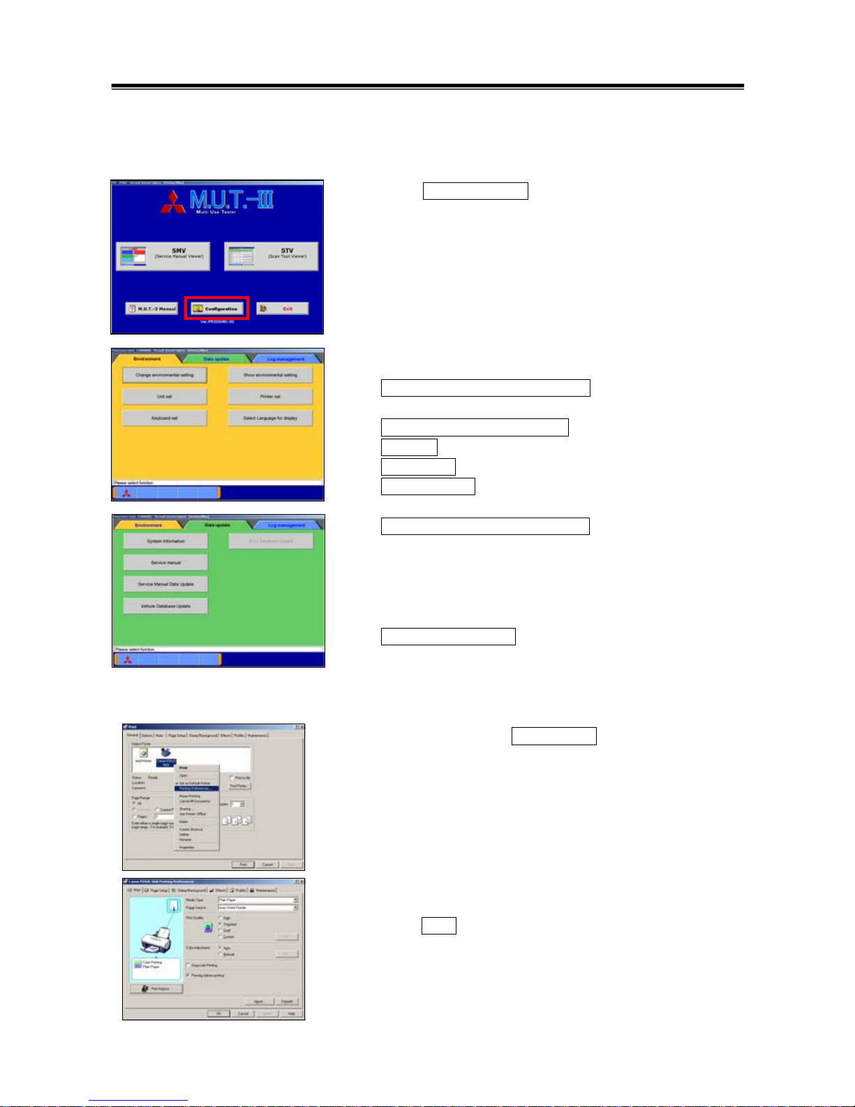
(1) Press Configuration button on the lower portion of the
M.U.T.-III Start Screen.
(2) Select a button corresponding to your purpose.
[ Environment ]
Change Environmental setting -- To set the driver, which
the Service manual data should be installed.
Show environmental setting -- To view the settings.
Unit set -- To select US unit or metric unit, e.g. lbs : kg
Printer set -- To set output conditions of the printer. (3-4-2.)
Keyboard set -- To select row of keys: Alphabetical-order or
QWERTY.
Select Language for display -- To select a language
displayed in whole M.U.T.-III system and Service manuals.
(Service manual will not be displayed unless the selected
language has been downloaded.)
[ Data Update ]
System Information -- To view versions of installed software
on the PC.
3-4-2. Set up Output conditions of Printer
(1) When pressing the Printer set button on 3-4-1(2), the
“Printer” window illustrated on the left appears.
Select an appropriate printer icon and right-click it to open a
pull-down menu; select “Printing Preferences…”.
Note
-Set up conditions on this window will not be reflected.
(2) The “Printing Preferences” window of the selected printer
appears. Please set output conditions e.g. page setup, and
press OK button.
[ Environment ]
Option Settings
[ Data Update ]
20
3-5. Useful Functions
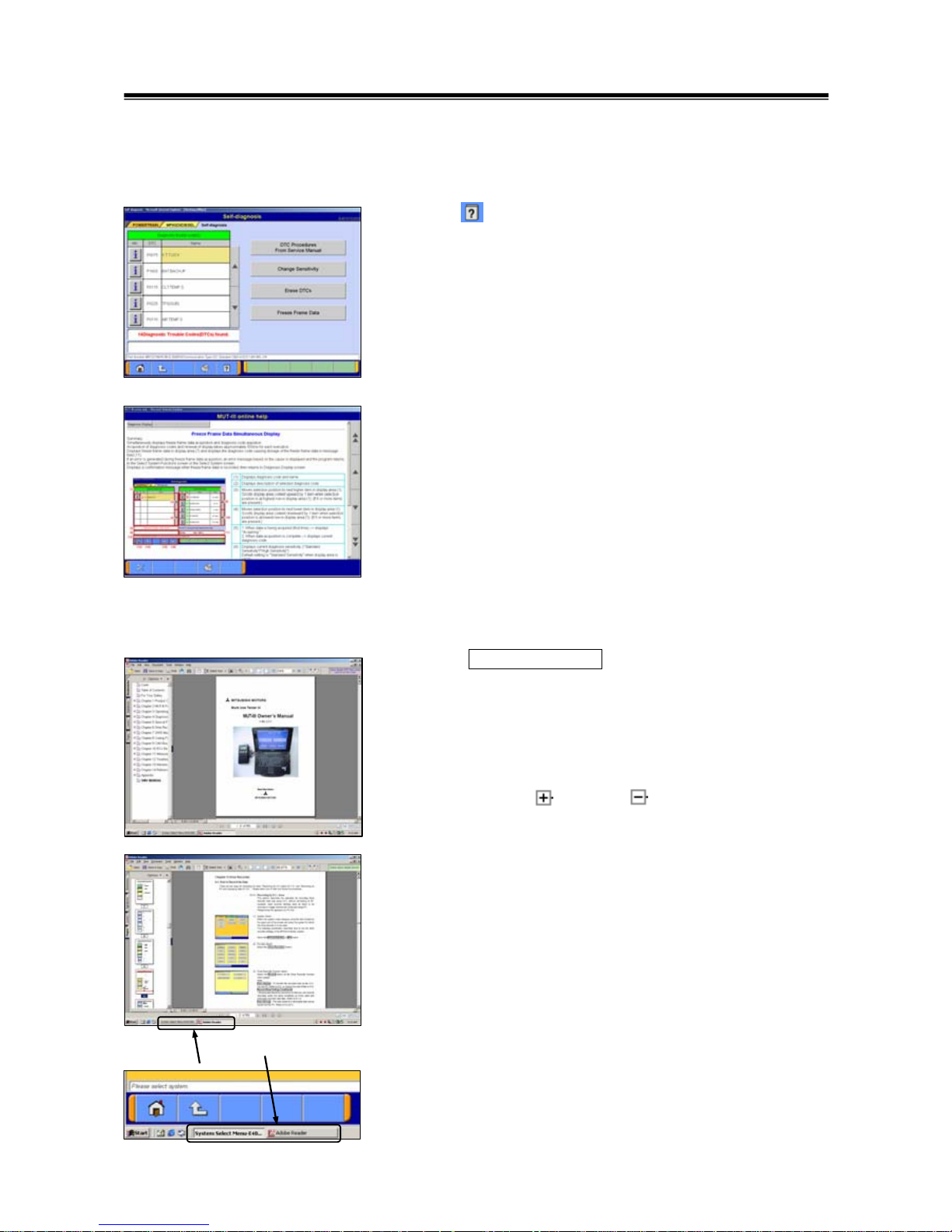
3-5-1. Online Help Function
(1) The
button on each screen is the online help button for
that screen.
(2) The online help function allows you to view a general
overview of each screen and refer to explanations of the
various button functions. If you wish to move the screen up or
down, select the applicable scroll button located on the right
side of the screen
.
3-5-2. Display “M.U.T.-III Owner’s Manual”
Press M.U.T.-3 Manual button at the lower-left portion of
the M.U.T.-III Start Screen, then this Adobe Acrobat Reader
“M.U.T.-III Owner’s Manual” starts.
Select “Bookmarks” tab at far left of the window.
-When you select a title on the left column, you can jump into
the corresponding page.
-When you click , it turns to , and titles in lower layer are
displayed.
Select “Pages” tab at far left of the window, then miniature
version of pages are displayed on the left column. It shows
currently displayed page with red frame so that you can see
where the page is.
Selecting M.U.T.-III system or “Adobe Reader” appearing as
buttons on the Taskbar switches between the system and the
manual. You can hereby readily check this manual while
operating M.U.T.-III system.
Useful Functions
Taskbar
21
Chapter 4 Diagnosis Function
4-1. Diagnostic Trouble Code
4-1-1. Reading and Erasing Diagnostic Trouble Code (DTC)
(1) Select a system that you want to diagnose on the System
Selection screen. (For instruction on how to select a system,
refer to 3-3-1)
- In the explanation that follows, the method is explained
using the MPI/GDI/Diesel system as a representative
example.
Note:
If the engine is OBD, a check code appears.
(2) Press Self-diagnosis button.
The system automatically communicates with the vehicle
ECU and obtains the diagnostic trouble codes (DTCs).
(3) Diagnostic trouble codes (DTCs) of the selected system,
which is currently stored in the vehicle ECU, are listed.
DTC Procedures From Service Manual
--Switches the mode to interactive fault diagnosis mode.
(refer to 4-1-2)
(Not Available in US)
Change Sensitivity --Allows you to increase the
diagnostic code detection capability of the ECU or return
the sensitivity level back to normal.
Erase DTCs --Deletes the diagnostic trouble codes.
Freeze Frame Data --Displays the Freeze frame data.
Diagnostic Trouble Code
22
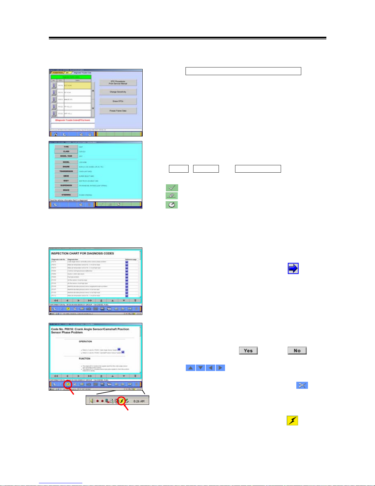
4-1-2. Interactive Fault Diagnosis Mode
(1) Press DTC Procedures From Service Manual button.
Note:
It is not necessary to select DTC code to be diagnosed.
(2) Vehicle Information Setting Screen
-Currently selected information is displayed in each item’s
field. (Blank space means the information is not selected.)
-
TYPE , CLASS and MODEL YEAR are compulsory
input.
--OK
--Deletes whole information
--Displays history of settings as open options.
Note:
In case you want to be Interactive diagnosis mode,
Workshop Manual data has to be installed into PC.
(3) Diagnosis codes chart Screen
Diagnosis codes of the selected vehicle are displayed.
In order to diagnose for current DTC, press button to
start troubleshooting.
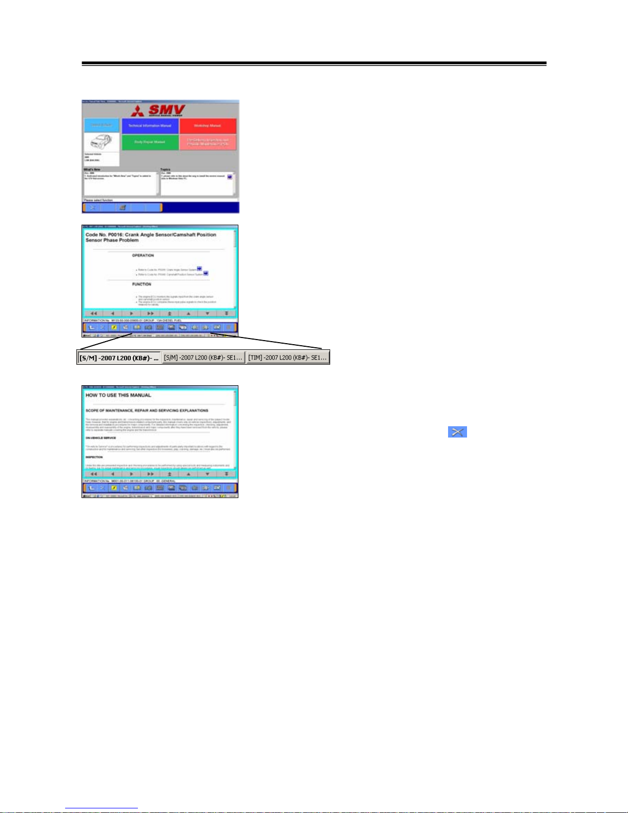
(4) Workshop Manual data of the selected DTC will be
displayed.
Proceed in accordance with displayed procedure on
Workshop Manual, press button or button
to go to next step.
Press button to scroll the screen up and
down, left and right movements.
When you finished your operation, press button
lower-left of the screen to close Workshop Manual screen.
On the Workshop Manual screen, another Workshop
Manuals can also be started up by pressing button.
As it enables to browse multiple Workshop Manuals, so it is
possible what Wiring diagram can be browsed while doing
diagnosis each DTC. -- to (5)
Diagnostic Trouble Code
23
(5) Workshop Manual select screen
Select manual to be browsed.
Note:
Select Vehicle button is not activated.
(6) Shift of Workshop Manual
Select content you want from Workshop Manuals displayed
on the task-bar button of the screen.
Note:
Workshop Manual in different kind of vehicles cannot be
browsed simultaneously.
(7) On Workshop Manual Viewer
SMV that would be started up for the first time is called
SMV(Main), and others are called SMV(Sub).
- When SMV(Main) will be closed by button, other
SMV(Sub) will be also closed altogether.
- Each Workshop Manual(Sub) can be closed individually.
- Select content you want from Workshop Manuals displayed
on the task-bar bottom of the screen.
Diagnostic Trouble Code
 Loading...