

Mitsubishi MCFH-18NV-WH, MCFH-24NV-E3, MCFH-24NV-WH, MUCFH-24NV- E3, MCFH-13NV-WH Service Manual
...
SERVICE MANUAL
(When installed on the ceiling)
(When installed on the floor)
FLOOR AND CEILING TYPE AIR CONDITIONERS
Wireless type
Models
Revision:
●MUCFH-18NV- has been added.
MUCFH-18NV- ➔ MUCFH-18NV-
•Path of outdoor heat exchanger has changed .
•Temperature range of high pressure protection has
changed.
•Please void OB267.
E4
E4E3
No. OB267
REVISED EDITION-A
MCFH-13NVMCFH-18NV-
MCFH-24NV-
(WH)
(WH)
(WH)
·MUCFH-13NV-
·MUCFH-18NV-
·MUCFH-18NV-
·MUCFH-24NV-
E4E4
E3E3
E4
E3E3
CONTENTS
1. TECHNICAL CHANGES ····································2
2. PART NAMES AND FUNCTIONS······················2
3. SPECIFICATION·················································5
4. NOISE CRITERIA CURVES·······························6
5. OUTLINES AND DIMENSIONS·························7
6. WIRING DIAGRAM ··········································10
7. REFRIGERANT SYSTEM DIAGRAM··············14
8. PERFORMANCE CURVES······························16
9. MICROPROCESSOR CONTROL ····················32
10. SERVICE FUNCTIONS·····································41
11. TROUBLESHOOTING······································42
12. DISASSEMBLY INSTRUCTIONS·····················55
13. PARTS LIST······················································63
14. OPTIONAL PARTS ······················BACK COVER
• Refer to service manual OB212 for MCFH-13/18/24/NV- , MUCFH-13/18/24/NV- ,
MCFH-13/18/24/NV- and MUCFH-13/18/24/NV- .
• Refer to service manual OB240 for MCFH-13NV- and MUCFH-13NV- .
• Refer to service manual OB185 REVISED EDITION-C for MCFH-13NV- or MCFH-18NV- is
connected with MXZ-32NV- .
• Refer to service manual OB227 REVISED EDITION-B for MCFH-13NV- or MCFH-18NV- is
connected with MXZ-32RV- .
• Refer to service manual OB254 for MCFH-13NV- or MCFH-18NV- is connected with
MXZ-32SV- .
• As for parts lists, all sub number’s series are included.
E1
E2
E1
E2E2
E1E1
E3E3
E3E4
E3E4
E3E4
1
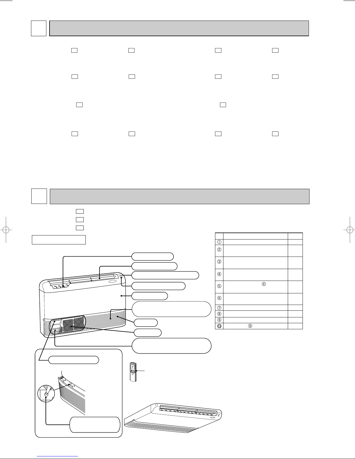
(When installed on the floor)
(When the air inlet grille is opened.)
Deodorizing filter
(gray sponge type)(option)
Air filter
Air inlet
Operation section
Air cleaning filter
(white bellows type)(option)
Front panel
Receiving section
Operation indicator lamp
Horizontal vane
Vertical vanes
Emergency
operation switch
(When installed on the ceiling)
ACCESSORIES
Item
Installation plate
Unit fixing screw
5 o 12mm
Wireless remote
controller
Remote controller
mounting hardware
Fixing screw for
3.5 o 16mm (Black)
Battery (AAA) for
remote controller
Drain hose
Drain pipe cover
Knockout cover
Screw for 4 o 10mm
2
2
1
1
2
2
1
1
1
2
Q'ty
Remote controller
TECHNICAL CHANGES
MCFH-13NV- · MUCFH-13NV- ➔ MCFH-13NV- · MUCFH-13NV-
1. Remote controller has changed.
SWING button is removed, but SWING MODE function is available by VANE CONTROL button.
MCHF-18NV- · MUCFH-18NV- ➔ MCFH-18NV- · MUCFH-18NV-
1. Remote controller has changed.
SWING button is removed, but SWING MODE function is available by VANE CONTROL button.
MUCFH-18NV- ➔ MUCFH-18NV-
1. Path of outdoor heat exchanger has changed .
2. Temperature range of high pressure protection has changed. (50:/46: ➔ 56:/52:)
E4E3
MCFH-24NV- · MUCFH-24NV- ➔ MCFH-24NV- · MUCFH-24NV-
1. Remote controller has changed.
SWING button is removed, but SWING MODE function is available by VANE CONTROL button.
2. Ball valve has changed to stop valve.
3. Deicer P.C. board has changed.
2
MCFH-13NV MCFH-18NV MCFH-24NV -
PART NAMES AND FUNCTIONS
E4
E3
E3
E4E4E3E3
E3E3E2E2
E3E3E2E2
INDOOR UNIT
2
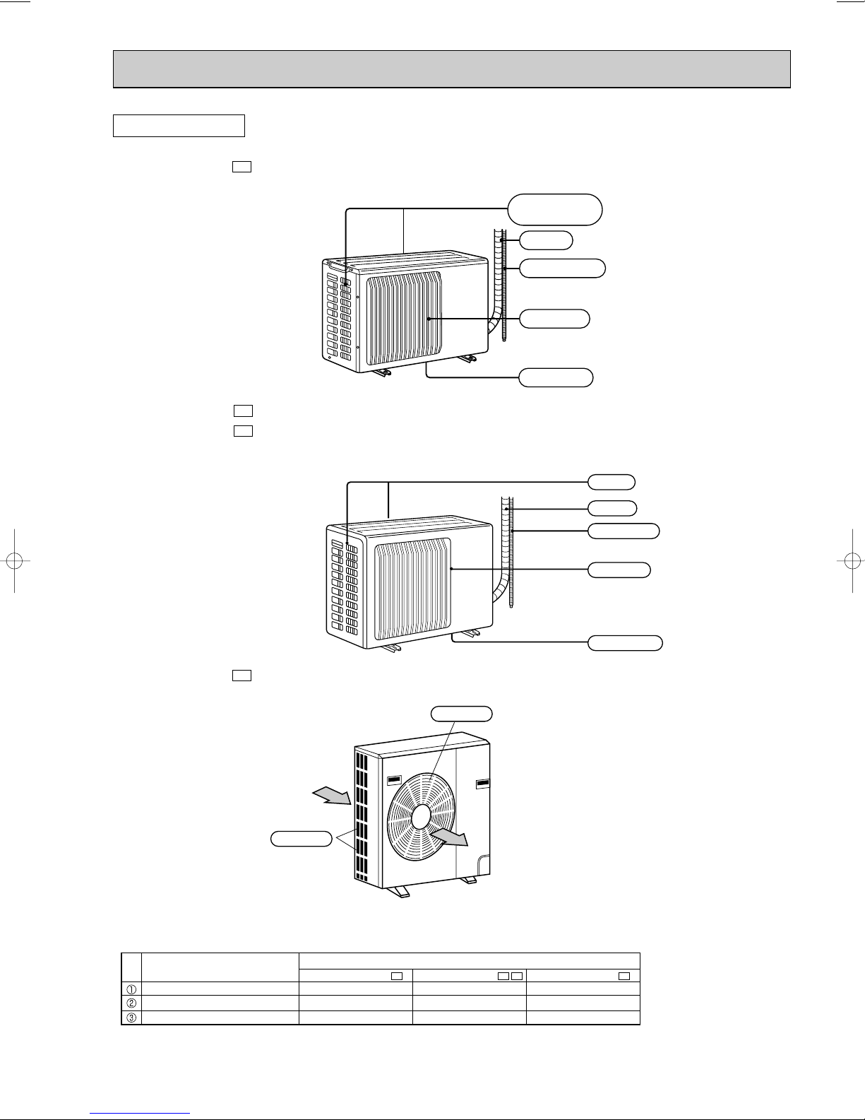
OUTDOOR UNIT
MUCFH-13NV -
MUCFH-18NV MUCFH-18NV -
E4
Air inlet
(back and side)
Piping
Drain hose
Air outlet
Drain outlet
E3
E4
Air inlet
Piping
Drain hose
Air outlet
MUCFH-24NV -
ACCESSORIES
Item
Drain socket
Drain cap [33
Drain cap [16
Drain outlet
E3
Air outlet
Air inlet
Q'ty
E4
MUCFH-13NV-
1
2
–
E4
MUCFH-18NV-
E3
MUCFH-24NV-
1
2
1
E3
1
6
–
3
ON/OFF
TOO
COOL
PM
AM
TOO
WARM
ON/OFF
FAN
TOO
WARM
TOO
COOL
VANE
MODE
STOP
START
HR.
MIN.
I FEEL
COOL
HEAT
DRY
PM
CLOCK
AM
RESET CLOCK
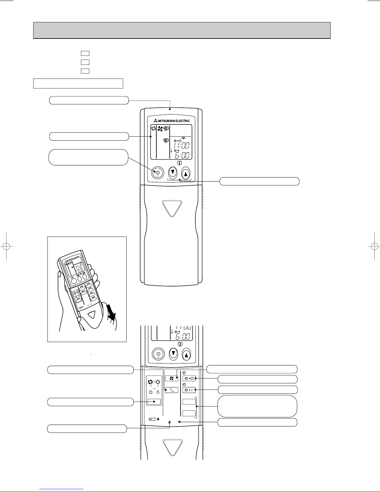
Open the front lid.
Signal transmitting section
Operation display section
OPERATE /STOP
(ON /OFF)button
TEMPERATURE buttons
OPERATION SELECT button
FAN SPEED CONTROL button
OFF-TIMER button
HR. button
MIN. button
(TIME SET button)
ON-TIMER button
RESET button
VANE CONTROL button
CLOCK SET button
MCFH-13NV MCFH-18NV MCFH-24NV -
E4
E3
E3
REMOTE CONTROLLER
4
3
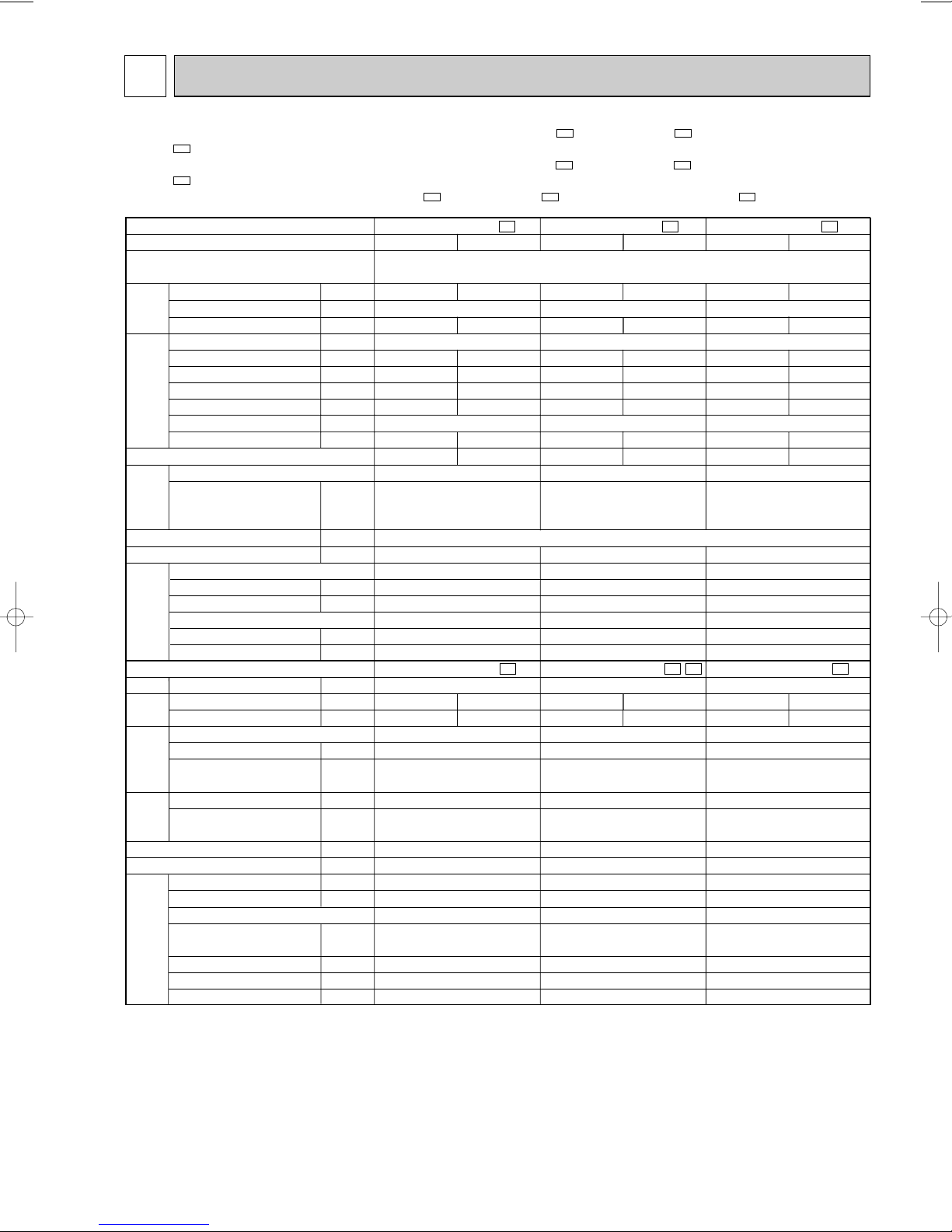
Indoor model
Function
Power supply
Capacity
Air flow(HighW/Med./Low)
Dehumidification
Power outlet
Running current
Power input
Auxiliary heater
Power factor
Starting current
Fan motor current
Model
Winding
resistance(at20:)
Dimensions WOHOD
Weight
Air direction
Sound level
(HighW/Med./Low)
Fan speed(HighW/Med./Low)
Fan speed regulator
Thermistor RT11(at25:)
Thermistor RT12(at25:)
Outdoor model
Air flow
Compressor motor current
Fan motor current
Model
Output
Winding
resistance(at20:)
Model
Winding
resistance(at20:)
Dimensions WOHOD
Weight
Sound level(High)
Fan speed
Fan speed regulator
Refrigerant filling
capacity(R22)
Refrigerating oil (Model)
Thermistor RT61(at0:)
Thermistor RT63(at0:)
kW
K /h
L/h
A
A
W
A(kW)
%
A
A
"
mm
kg
dB
rpm
k"
k"
K /h
A
A
W
"
"
mm
kg
dB
rpm
kg
cc
k"
k"
Electrical
data
Fan
motor
Special
remarks
Compressor
Electrical
data
Fan
motor
Special
remarks
Capacity
Coefficient of performance(C.O.P)
Capacity
MCFH-13NV-
E4
MCFH-18NV-
E3
MCFH-24NV-
E3
MUCFH-13NV-
E4
MUCFH-18NV-
E3
MUCFH-24NV-
E3
Cooling
3.7
1.5
6.2-6.4
1,310-1,400
—
96-91
0.30
2.82-2.64
5.54-5.72
0.36
Heating
4.0
—
5.4-5.8
1,130-1,220
—
95-88
0.30
3.54-3.28
4.74-5.12
0.38
780/636/492
10
35 - 38
RB4V25-AB
WHT-BLK 182.2 BLK-YLW 68.9
YLW-BLU 47.5 BLU-BRN 31.5
BRN-RED 22.9
26
5
46-47/41-43/35-37
1,220-1,260/1,020-1,100/810-880
3
10
10
1,656-1,758
RH-231VHAT
1,100
C-R 2.11 C-S 3.97
RA6V33-CA
WHT-BLK 176.0
BLK-RED 413.0
780 ✕ 540 ✕ 255
38
49-49
700-740
1
1.35
520 (MS56)
33.18
—
Cooling
5.0
2.6
9.3-9.0
2,030-2,120
—
99-98
0.36
2.46-2.36
8.55-8.25
0.39
Heating
5.4
—
8.9-8.6
1,910-2,010
—
98-97
0.36
2.83-2.69
8.15-7.85
0.39
Single phase
220-240 V, 50Hz
840/696/570
15
52 - 58
RB4V36-AB
WHT-BLK 82.9 BLK-YLW 65.6
YLW-BLU 36.0 BLU-BRN 27.0
BRN-RED 13.7
1100 ✕ 650 ✕ 180
26
5
48-48/43-45/38-40
1,310-1,330/1,120-1,170/920-1,000
3
10
10
2,142-2,244
NH-36VMDT
1,700
C-R 1.20 C-S 2.70
RA6V50-OG
WHT-BLK 116.4
BLK-RED 111.0
850 ✕ 605 ✕ 290
59
52-52
810-845
1
1.80
1,200 (MS32N1)
33.18
—
Cooling
6.0
3.1
12.5-11.7
2,720-2,750
—
99-98
0.36
2.21-2.18
11.56-10.76
0.58
Heating
6.2
—
11.7-11.3
2,540-2,650
—
99-98
0.36
2.44-2.34
10.76-10.36
0.58
840/696/570
25
59 - 59
RB4V36-AB
WHT-BLK 82.9 BLK-YLW 65.6
YLW-BLU 36.0 BLU-BRN 27.0
BRN-RED 13.7
26
5
48-48/43-45/38-40
1,310-1,330/1,120-1,170/920-1,000
3
10
10
High: 2,640-2,760/Low: 2,100-2,250
NH-47VMDT
2,200
C-R 0.96 C-S 2.07
RA6V85-AA
WHT-BLK 62.7 BLK-YLW 30.2
YLW-RED 62.9
870 ✕ 850 ✕ 295
72
53-53
High: 720-750/Low: 570-610
2
2.40
1,200 (MS32N1)
33.18
33.18
E4
SPECIFICATION
• Refer to service manual OB185 REVISED EDITION-C for MCFH-13NV- or MCFH-18NV- is connected with MXZ-
E2
32NV- .
• Refer to service manual OB227 REVISED EDITION-B for MCFH-13NV- or MCFH-18NV- is connected with MXZ-
E1
32RV- .
• Refer to service manual OB254 for MCFH-13NV- or MCFH-18NV- is connected with MXZ-32SV- .
NOTE: w The values of Electrical data indicated on the specification are based on the high speed operation of the fan.
Test conditions are based on ISO 5151
Cooling : Indoor DB27°C WB19°C Heating : Indoor DB20°C WB 15°C
Indoor-Outdoor piping length 5 m
Outdoor DB35°C WB(24°C) Outdoor DB 7°C WB 6°C
5
E3E4
E3E4
E1E3E4
4
NOISE CRITERIA CURVES
MCFH-13NV -
90
E4
SPEED
High
SPL(dB
46-47
Test conditions,
Cooling : DB 27: WB 19:\
Heating : DB 20: WB 15:
80
70
60
50
40
30
APPROXIMATE
20
THRESHOLD OF
HEARING FOR
CONTINUOUS
NOISE
OCTAVE BAND SOUND PRESSURE LEVEL, dB re 0.002 MICRO BAR
10
63 125 250 500 1000 2000 4000 8000
BAND CENTER FREQUENCIES, Hz
MCFH-18NV -
E3
SPL(dB
SPEED
(A)) LINE
(A)) LINE
MUCFH-13NV -
90
80
NC-70
70
60
NC-60
50
NC-50
40
NC-40
30
NC-30
20
NC-20
OCTAVE BAND SOUND PRESSURE LEVEL, dB re 0.002 MICRO BAR
10
MUCFH-18NV MUCFH-18NV -
E4
APPROXIMATE
THRESHOLD OF
HEARING FOR
CONTINUOUS
NOISE
SPEED
High
SPL(dB
(A)) LINE
49-49
Test conditions,
Cooling : DB 35: WB (24:)
Heating : DB 7: WB 6:
63 125 250 500 1000 2000 4000 8000
BAND CENTER FREQUENCIES, Hz
E3
E4
SPEED
SPL(dB
(A)) LINE
NC-70
NC-60
NC-50
NC-40
NC-30
NC-20
High
Test conditions,
Cooling : DB 27: WB 19:\
90
Heating : DB 20: WB 15:
48-48
80
70
60
50
40
30
APPROXIMATE
20
THRESHOLD OF
HEARING FOR
CONTINUOUS
NOISE
OCTAVE BAND SOUND PRESSURE LEVEL, dB re 0.002 MICRO BAR
10
63 125 250 500 1000 2000 4000 8000
BAND CENTER FREQUENCIES, Hz
NC-70
NC-60
NC-50
NC-40
NC-30
NC-20
High
Test conditions,
Cooling : DB 35: WB (24:)
90
Heating : DB 7: WB 6:
52-52
80
70
60
50
40
30
APPROXIMATE
20
THRESHOLD OF
HEARING FOR
CONTINUOUS
NOISE
OCTAVE BAND SOUND PRESSURE LEVEL, dB re 0.002 MICRO BAR
10
63 125 250 500 1000 2000 4000 8000
BAND CENTER FREQUENCIES, Hz
NC-70
NC-60
NC-50
NC-40
NC-30
NC-20
6
MCFH-24NV -
E3
MUCFH-24NV -
E3
SPL(dB
SPEED
High
Test conditions,
Cooling : DB 27: WB 19:\
90
80
70
60
50
40
30
APPROXIMATE
20
THRESHOLD OF
HEARING FOR
CONTINUOUS
NOISE
OCTAVE BAND SOUND PRESSURE LEVEL, dB re 0.002 MICRO BAR
10
63 125 250 500 1000 2000 4000 8000
BAND CENTER FREQUENCIES, Hz
Heating : DB 20: WB 15:
(A)) LINE
48-48
NC-70
NC-60
NC-50
NC-40
NC-30
NC-20
SPL(dB
SPEED
High
Test conditions,
Cooling : DB 35: WB (24:)
90
80
70
60
50
40
30
APPROXIMATE
20
THRESHOLD OF
HEARING FOR
CONTINUOUS
NOISE
OCTAVE BAND SOUND PRESSURE LEVEL, dB re 0.002 MICRO BAR
10
63 125 250 500 1000 2000 4000 8000
BAND CENTER FREQUENCIES, Hz
Heating : DB 7: WB 6:
(A)) LINE
53-53
NC-70
NC-60
NC-50
NC-40
NC-30
NC-20
5
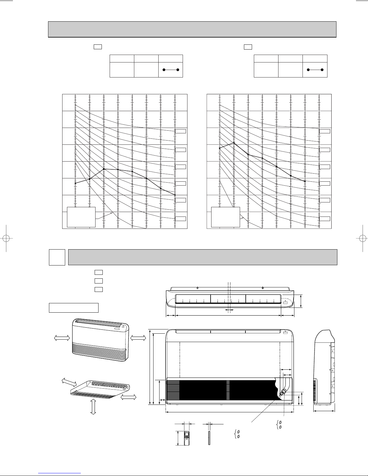
OUTLINES AND DIMENSIONS
MCFH-13NV MCFH-18NV MCFH-24NV -
INDOOR UNIT
(When installed on the floor)
50cm or more
50cm or more
(When installed on the ceiling)
E4
E3
E3
100cm or more
50cm or more
50cm or more
80.8 906 112.8
650
616.5
16
17042.5
1100
58
19
Liquid line
6.35 (MCFH-13/18)
162
9.52 (MCFH-24)
114
93
77
113
Gas line
12.7 (MCFH-13)
15.88 (MCFH-18/24)
Unit: mm
143
180
Wireless remote controller
7
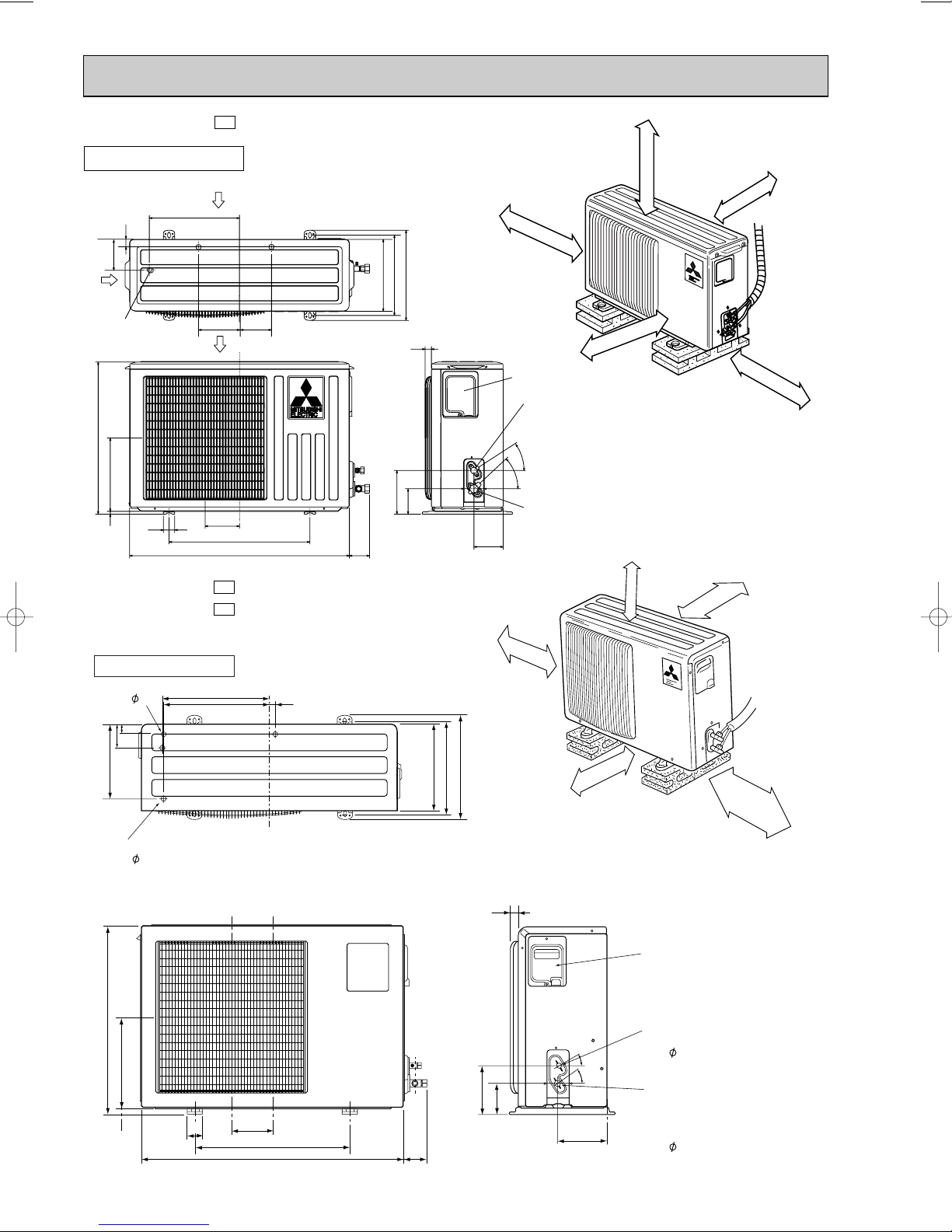
OUTDOOR UNIT
100mm or more
100mm or more
100mm or more
500mm or more
350mm or more
350
355
Drainage
3holes 33
35
248
20
290
310
345
90
Drainage
hole 16.2
320
25
43-
35-
155
90
104
74
260
10
780
500
122
40
540
320
285
255
Service panel
Gas refrigerant
pipe joint
Refrigerant pipe
(flared) [12.7
Liquid refrigerant
pipe joint
Refrigerant pipe
(flared) [6.35
Airout
Air in
Air in
109
32
110
147
Drainage
3holes [33
MUCFH-13NV -
OUTDOOR UNIT
E4
Unit: mm
REQUIRED SPACE
MUCFH-18NV MUCFH-18NV -
Outdoor
100mm or more
E3
E4
unit
400mm or more
100mm or more
100mm or more
350mm or more
50
133
500
850
605
29220
74
30
157
100
8
161
30
35
Service panel
Liquid refrigerant
pipe joint
Refrigerant pipe
(flared)
6.35
Gas refrigerant
pipe joint
Refrigerant pipe
(flared)
15.88
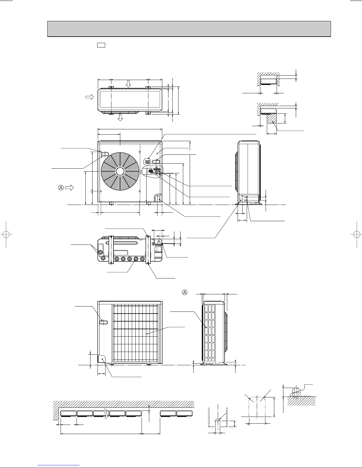
MUCFH-24NV -
E3
Unit: mm
Outdoor Unit-Necessary surrounding clearance
Outlet guide
installation hole
Handle for moving
Drain hole
Air intake
441
179 524
40 60524
185
Air outlet
302
2-12o23 Oval holes
(standard bolt M10)
500
Air intake
870
468
185
1715
330
362
39.5 27.5
Terminal block for indoor and outdoor unit connection
Service panel
Handle for moving
Refrigerant-pipe flared
850
connection [15.88
553
Refrigerant-pipe flared
450
connection [9.52
Knock out hole
for front piping
(refrigerant,drainage
and wiring)
Knock out hole
45
for right piping
(refrigerant,drainage
and wiring)
104
445
33
42
Bottom
piping hole
10
10
60
Knock out holes for
120
power line 2-[27
Front opening
500
4553
200
Note:Allow adequate
upper clearance
10
150
500
Service space
Drain hole
Handle
for moving
138
95
Rear piping hole
Outdoor Unit-Necessary surrounding clearance
(Concentrated installation)
100 10
The upper side must be open.
200
1000For 10 units or less
2-U-shaped
notched
holes
Side air intake
Rear fresh
air intake
724
295
23
12
R6
33
R20
17
Front right piping holesdetail figures
R20
80
25 max.
65
Standard bolt length
9
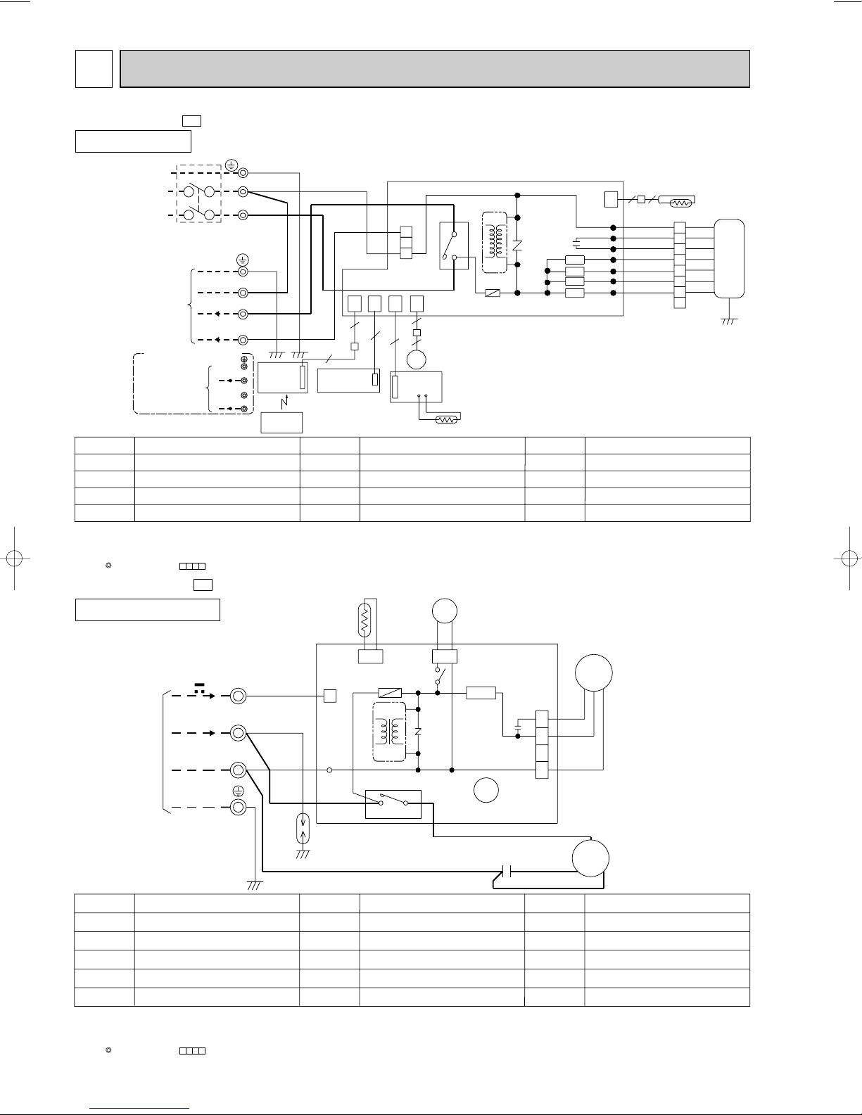
WIRING DIAGRAM6
FROM INDOOR UNIT
CONNECTING
X62
DEICER P.C. BOARD
CN730
SR61
TAB20
1
43
TRANS
52C
IC881
NR61
RT61
X62
F61
CN661
BLK
BLK
CN721
21S4
S
WHT
BLK
C1
RED
R
C
MC
C65
CN711
4
3
1
2
BLK
WHT
RED
MF
220-240V~
12V
RED
BLU
GRN/YLW
DSAR
WHT
BLU
WHT
N
2
TB
3
MCFH-13NV -
INDOOR UNIT
CIRCUIT BREAKER
TO OUTDOOR
UNIT
CONNECTING
TO OUTDOOR
UNIT
CONNECTING
SYMBOL
C11
INDOOR FAN CAPACITOR
F11
FUSE (3.15A)
HIC1
NOTE:1. About the outdoor side electric wiring, refer to the outdoor unit electric wiring diagram for servicing.
DC/DC DONVERTER
MF
INDOOR FAN MOTOR(INNER PROTECTOR)
2. Use copper conductors only.(For field wiring)
3. Symbols below indicate;
: Terminal block, : Connector
MUCFH-13NV -
E4
MODEL WIRING DIAGRAM
TB
N
L
POWER SUPPLY
~/N 220-240V
50Hz
220-240V~
12VDC
FOR MULTI SYSTEM
12V DC
NAME
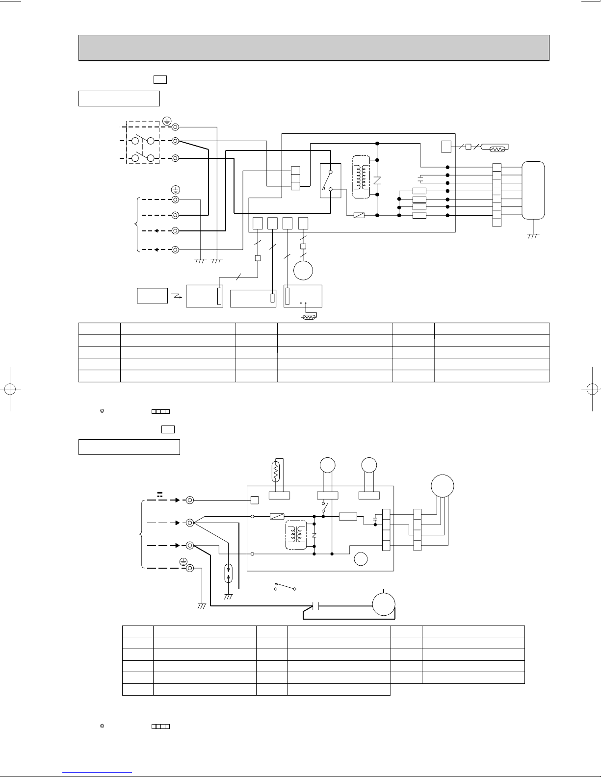
E4
MODEL WIRING DIAGRAM
PE
GRN/YLW
N
BLU
2
WHT
3
RED
DISP/
N
RECEIVER
P.C.BOARD
2
3
GRN/YLW
BLU
BRN
REMOTE
CONTROLLER
5
AUTO RESTART
ASSY
SYMBOL
MV
NR11
RT11
RT12
HIC1
3
2
1
CN201
4
52C
3
TRANS
F11
CN
CN
CN
101CN113
104
5
151
ELECTRONIC CONTROL P.C BOARD
6
5
4
5
MV
SW/THERMO
P.C.BOARD
RT11
NAME NAME
VANE MOTOR
VARISTOR
ROOM TEMPERATURE THERMIST OR
INDOOR COIL THERMISTOR
LDCOM
C11
NR11
SR144
SR143
SR142
SR141
SYMBOL
SR141~SR144
SW/THERMO
P.C. BOARD
TB
52C
22
CN
112
WHT
WHT
LDC11
LDC12
LDFH
LDFM
LDFL
LDFVL
ORN
RED
BLK
YLW
BLU
BRN
1
ORN
2
RED
3
BLK
4
YLW
5
BLU
6
BRN
7
8
GRN/YLW
SOLID STATE RELAY
SWITCH & ROOM TEMPERATURE
THERMISTOR P.C. BOARD
TERMINAL BLOCK
CONTACTOR
VG79B037H02
RT12
MF
OUTDOOR UNIT
SYMBOL
C1
C65
DSAR
F61
IC881
NOTE:1. About the indoor side electric wiring, refer to the indoor unit electric wiring diagram for servicing.
2. Use copper conductors only.(For field wiring)
3. Symbols below indicate;
: Terminal block, : Connector
COMPRESSOR CAPACITOR
OUTDOOR FAN CAPACITOR
SURGE ABSORBER
FUSE(2A)
DC/DC CONVERTER
NAME
SYMBOL
MC
MF
NR61
RT61
SR61
COMPRESSOR(INNER PROTECTOR)
OUTDOOR FAN MOTOR(INNER PROTECTOR)
VARISTOR
DEFROST THERMISTOR
SOLID STATE RELAY
NAME NAME
10
SYMBOL
21S4
TB
X62
52C
TERMINAL BLOCK
R.V. COIL RELAY
R.V. COIL
COMPRESSOR CONTACTOR
VG79B013H01
SYMBOL
SR141~SR144
SW/THERMO
P.C. BOARD
TB
52C
SYMBOL
MV
NR11
RT11
RT12
SYMBOL
C11
F11
HIC1
MF
NAME
NAME NAME
INDOOR FAN CAPACITOR
FUSE (3.15A)
DC/DC DONVERTER
INDOOR FAN MOTOR(INNER PROTECTOR)
VANE MOTOR
VARISTOR
ROOM TEMPERATURE THERMIST OR
INDOOR COIL THERMISTOR
SOLID STATE RELAY
SWITCH & ROOM TEMPERATURE
THERMISTOR P.C. BOARD
TERMINAL BLOCK
CONTACTOR
MCFH-18NV -
INDOOR UNIT
CIRCUIT BREAKER
POWER SUPPLY
~/N 220-240V
50Hz
TO OUTDOOR
UNIT
CONNECTING
220-240V~
12VDC
E3
MODEL WIRING DIAGRAM
TB
PE
GRN/YLW
N
BLU
L
BRN
GRN/YLW
N
BLU
2
WHT
3
RED
CN
CN
101
104
5
5
5
CN201
CN
113
22
WHT
ORN
RED
BLK
YLW
BLU
BRN
WHT
1
ORN
2
RED
3
BLK
4
YLW
5
BLU
6
BRN
7
8
GRN/YLW
RT12
MF
HIC1
3
2
1
4
52C
3
TRANS
F11
CN
151
ELECTRONIC CONTROL P.C BOARD
NR11
C11
SR144
SR143
SR142
SR141
LDCOM
LDC11
LDC12
LDFH
LDFM
LDFL
LDFVL
112
CN
6
5
4
MV
REMOTE
CONTROLLER
NOTE:1. About the outdoor side electric wiring, refer to the outdoor unit electric wiring diagram for servicing.
2. Use copper conductors only.(For field wiring)
3. Symbols below indicate;
: Terminal block, : Connector
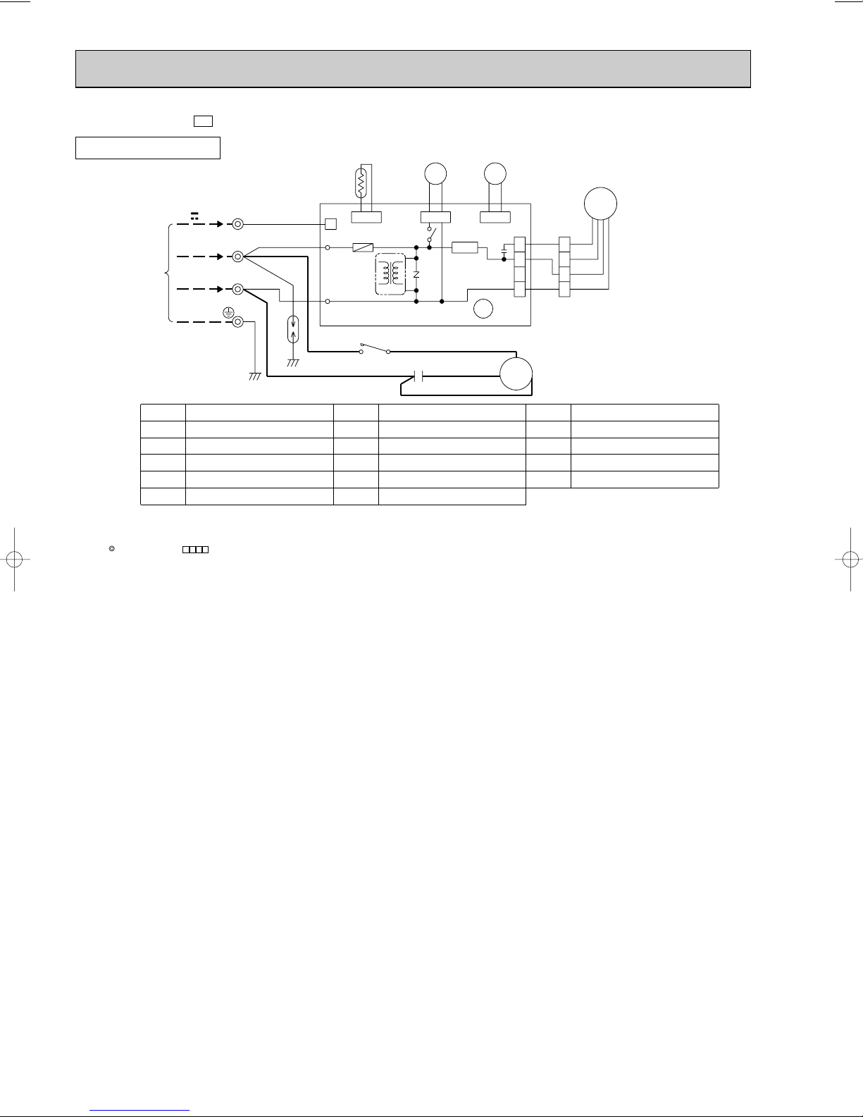
MUCFH-18NV -
DISP/
RECEIVER
P.C.BOARD
E3
MODEL WIRING DIAGRAM
OUTDOOR UNIT
12V
220-240V~ 2
FROM INDOOR UNIT
CONNECTING
SYMBOL
C1
COMPRESSOR CAPACITOR
C65
OUTDOOR FAN CAPACITOR
DSAR
NOTE:1. About the indoor side electric wiring, refer to the indoor unit electric wiring diagram for servicing.
2. Use copper conductors only.(For field wiring)
3. Symbols below indicate;
: Terminal block, : Connector
SURGE ABSORBER
F61
FUSE (2A)
IC881
DC/DC CONVERTER
TB
3
N
GRN/YLW
NAME
AUTO RESTART
ASSY
SW/THERMO
P.C.BOARD
RT61
CN730
RED
WHT
WHT
BLU
DSAR
1
TAB21
TAB20
NO COM
WHT
CN661
IC881
TRANS
X62
F61
DEICER P.C. BOARD
52C
BLU
SYMBOL
MC
COMPRESSOR (INNER PROTECTOR)
FAN MOTOR (INNER PROTECTOR)
MF
NR61
VARISTOR
RT61
DEFROST THERMISTOR
SR61
SOLID STATE RELAY
11
RT11
21S4
BLK
BLK
CN721
SR61
NR61
WHT
C1
RED
BLK
NAME
52C
VLT
VLT
CN720
REDRED
WHT
BLK
1
2
3
4
ORN
WHT
BLK
X62
1
C65
2
3
4
CN711
C
MC
RS
SYMBOL
TB
TERMINAL BLOCK
X62
R.V. COIL RELAY
21S4
R.V. COIL
52C
COMPRESSOR CONTACTOR
VG79B034H02
MF
NAME
SG79J011H01
MUCFH-18NV -
E4
MODEL WIRING DIAGRAM
OUTDOOR UNIT
X62
C1
21S4
BLK
CN721
NR61
NAME
BLK
RT61
12V
220-240V~ 2
FROM INDOOR UNIT
CONNECTING
SYMBOL
C1
COMPRESSOR CAPACITOR
C65
OUTDOOR FAN CAPACITOR
DSAR
SURGE ABSORBER
F61
FUSE (2A)
IC881
DC/DC CONVERTER
NOTE:1. About the indoor side electric wiring, refer to the indoor unit electric wiring diagram for servicing.
2. Use copper conductors only.(For field wiring)
3. Symbols below indicate;
: Terminal block, : Connector
3
N
TB
RED
WHT
BLU
GRN/YLW
NAME
WHT
DSAR
CN730
1
TAB21
TAB20
NO COM
WHT
BLU
SYMBOL
MC
MF
NR61
RT61
SR61
CN661
F61
IC881
TRANS
DEICER P.C. BOARD
52C
COMPRESSOR (INNER PROTECTOR)
FAN MOTOR (INNER PROTECTOR)
VARISTOR
DEFROST THERMISTOR
SOLID STATE RELAY
52C
VLT
CN720
SR61
X62
WHT
RED
BLK
VLT
1
C65
2
3
4
CN711
MC
WHT
BLK
C
RS
SYMBOL
TB
X62
21S4
52C
MF
REDRED
1
ORN
2
WHT
3
BLK
4
NAME
TERMINAL BLOCK
R.V. COIL RELAY
R.V. COIL
COMPRESSOR CONTACTOR
SG79B116H01
12
SYMBOL
SR141~SR144
SW/THERMO
P.C. BOARD
TB
52C
SYMBOL
MV
NR11
RT11
RT12
SYMBOL
C11
F11
HIC1
MF
NAME
NAME NAME
INDOOR FAN CAPACITOR
FUSE (3.15A)
DC/DC DONVERTER
INDOOR FAN MOTOR(INNER PROTECTOR)
VANE MOTOR
VARISTOR
ROOM TEMPERATURE THERMISTOR
INDOOR COIL THERMISTOR
SOLID STATE RELAY
SWITCH & ROOM TEMPERATURE
THERMISTOR P.C. BOARD
TERMINAL BLOCK
CONTACTOR
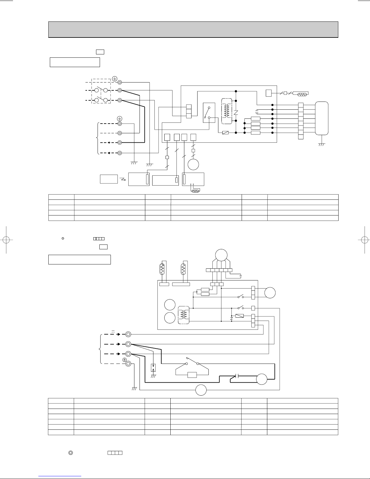
MCFH-24NV -
INDOOR UNIT
CIRCUIT BREAKER
POWER SUPPLY
~/N 220-240V
50Hz
TO OUTDOOR
UNIT
CONNECTING
E3
220-240V~
12VDC
REMOTE
CONTROLLER
MODEL WIRING DIAGRAM
TB
PE
GRN/YLW
N
L
GRN/YLW
N
BLU
2
WHT
3
RED
BLU
BRN
DISP/
RECEIVER
P.C.BOARD
CN
CN
104
101
5
5
AUTO RESTART
ASSY
3
2
1
CN201
CN
CN
113
151
5
4
MV
SW/THERMO
P.C.BOARD
HIC1
4
52C
3
TRANS
F11
C11
NR11
SR144
SR143
SR142
SR141
ELECTRONIC CONTROL P.C BOARD
6
5
RT11
LDCOM
LDC11
LDC12
LDFH
LDFM
LDFL
LDFVL
CN
112
22
WHT
ORN
RED
BLK
YLW
BLU
BRN
WHT
1
ORN
2
RED
3
BLK
4
YLW
5
BLU
6
BRN
7
8
GRN/YLW
RT12
MF
NOTE:1. About the outdoor side electric wiring, refer to the outdoor unit electric wiring diagram for servicing.
2. Use copper conductors only.(For field wiring)
3. Symbols below indicate;
: Terminal block, : Connector
E3
MUCFH-24NV -
OUTDOOR UNIT
MODEL WIRING DIAGRAM
RT61
CN661
X62
X52
TB
12V
220-240V~
3
2
RT63
CN662
T61
MF
ORN
WHT
BLK
YLW
6543
SR62
SR61
DEICER P.C. BOARD
RED
12
BLK
WHT
321
ORN
CN711
YLW
X62
COM
X52
COM
NR61
RED
N
FROM INDOOR UNIT
CONNECTING
DSAR
WHT
WHT
WHT
BLU
GRN/YLW
BLU
52C
CZ
21
WHT
52C
A1A2
F61
CN730
C1
C2
CN721
NO
TAB52
NO
WHT
RED
BLK
VG79B035H02
1
21S4
2
3
1
3
5
S
MC
R
RED
BLU
C
WHT
BLU
SYMBOL
CZ
CZ SURGE ABSORBER
C1
COMPRESSOR CAPACITOR
C2
DSAR
NOTES:
OUTDOOR FAN CAPACITOR
SURGE ABSORBER
F61
FUSE(3.15A)
MC
COMPRESSOR (INNER PROTECTOR)
1.Use copper conductors only (For field wiring).
2.Since the indoor and outdoor unit connecting wires have polarity, connect them according to the numbers (3,2,N).
3.Symbols below indicate.
:Terminal block, :Connector
NAME
SYMBOL
OUTDOOR FAN MOTOR (INNER PROTECTOR)
MF
NR61
RT61
RT63
SR61
SR62
VARISTOR
DEFROST THERMISTOR
AMBIENT TEMPERATURE THERMISTOR
SOLID STATE RELAY
SOLID STATE RELAY
13
NAME NAME
SYMBOL
TB
T61
X52
X62
21S4
52C
TERMINAL BLOCK
TRANSFORMER
CONTACTOR
R.V. COILRELAY
R.V. COIL
COMPRESSOR CONTACTOR
SG79J184H01
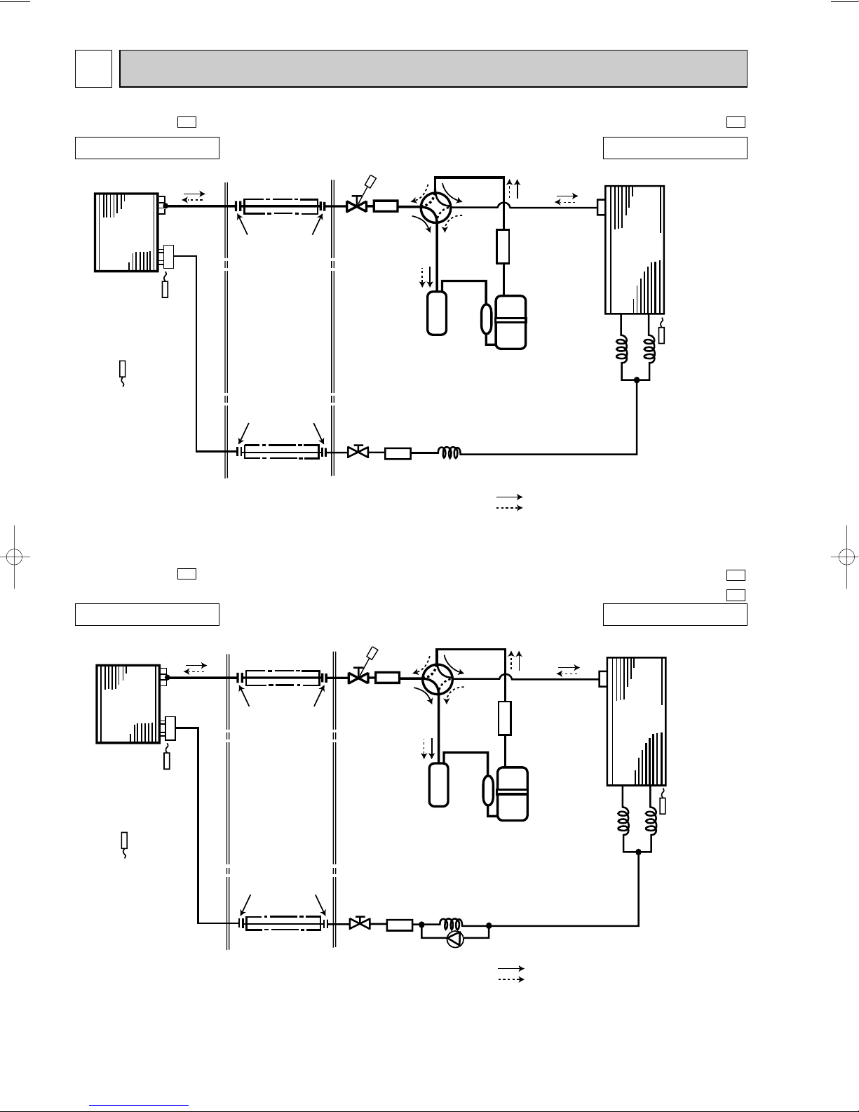
REFRIGERANT SYSTEM DIAGRAM7
Indoor
heat
exchanger
Outdoor
heat
exchanger
Distributor
Flared connection
Room temperature
thermistor
RT11
Coil temperature
thermistor
RT12
Defrost
thermistor
RT61
Flared connection
Stop valve
Stop valve
(with service port)
Strainer
Capillary tube
[3.0o[1.8o200
Capillary tube
[3.0o[1.4o500
Refrigerant flow in cooling
Compressor
Accumulator
Strainer
Muffler
4-way valve
Refrigerant flow in heating
Refrigerant pipe [12.7
(with heat insulator)
Refrigerant pipe
[6.35
(with heat insulator)
R.V.coil
heating ON
cooling OFF
Capillary
tube
[3.0o[1.4o500
MCFH-13NV-
Unit : mm
E4
MUCFH-13NV-
E4
INDOOR UNIT
OUTDOOR UNIT
MCFH-18NV-
INDOOR UNIT
Coil temperature
thermistor
RT12
Room temperature
thermistor
RT11
Indoor
heat
exchanger
E3
Refrigerant pipe [15.88
(with heat insulator)
Distributor
Flared connection
Flared connection
Refrigerant pipe
[6.35
(with heat insulator)
Stop valve
(with service port)
Stop valve
4-way valve
Muffler
Accumulator
Strainer Capillary tube
Check
valve
MUCFH-18NVMUCFH-18NVOUTDOOR UNIT
Outdoor
Strainer
Compressor
Capillary tube
[3.0o[1.6o750
[3.0o[2.0o600
Refrigerant flow in cooling
Refrigerant flow in heating
heat
exchanger
Defrost
thermistor
RT61
Capillary
tube
[3.0o[1.6o750
R.V.coil
heating ON
cooling OFF
E3
E4
14
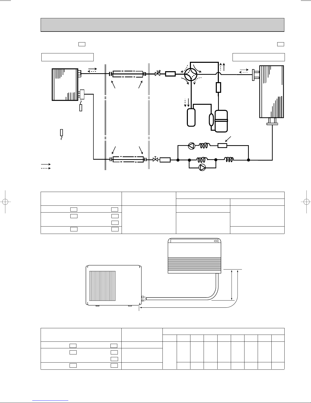
MCFH-24NV-
A: Refrigerant piping Max.length 15m
W Max. Height
difference
5m
Unit : mm
E3
MUCFH-24NV-
E3
INDOOR UNIT
Refrigerant pipe [15.88
4-way valve
(with heat insulator)
Muffler
Indoor
heat
exchanger
Coil temperature
thermistor
RT12
Distributor
Flared connection
Stop valve
(with service port)
Strainer
Compressor
Accumulator
Capillary tube
[3.0o[1.6o350
Capillary tube
Check
valve
[3.0o[2.0o350
Capillary tube
[4.0o[2.4o200
Room temperature
thermistor
RT11
Refrigerant flow in cooling
Refrigerant flow in heating
Flared connection
Refrigerant pipe
[9.52
(with heat insulator)
Strainer
Stop valve
Check
valve
MAX. REFRIGERANT PIPING LENGTH & MAX. HEIGHT DIFFERENCE
Model
MCFH-13NV - MUCFH-13NV MCFH-18NV - MUCFH-18NV -
MUCFH-18NV -
MCFH-24NV - MUCFH-24NV -
wIt does not matter which unit is higher.
Refrigerant piping
MAX. length :mm
A
E4E4
E3E3
E4
E3E3
15
Piping size O.D. : mm
Gas
{12.7
{15.88
OUTDOOR UNIT
Outdoor
heat
exchanger
Discharge pressure
regurator open
2.30MPa
(23.5kgf/F)
R.V.coil
heating ON
cooling OFF
Liquid
{6.35
{9.52
ADDITIONAL REFRIGERANT CHARGE (R22 : g)
If pipe length exceeds 7m, additional refrigerant (R22) charge is required
Models
MCFH-13NV - MUCFH-13NV MCFH-18NV - MUCFH-18NV -
MUCFH-18NV -
MCFH-24NV - MUCFH-24NV -
Calculation : (MCFH-13/18NV)✕g=50g/m✕(Refrigerant piping length (m)-7)
(MCFH-24NV)✕g=65g/m✕(Refrigerant piping length (m)-7)
Outdoor unit:precharged
E4E4
E3E3
E4
E3E3
1,350
1,800
2,400
7m08m509m
15
Refrigerant piping length (one way)
10m
11m
12m
100
150
200
250
65
130
195 260
325
13m
14m
15m
300
350
400
390 455 520
8
Air in
Air out
Wet and dry-bulb
thermometers
FRONT VIEW
Wet and dry-bulb
thermometers
BACK VIEW
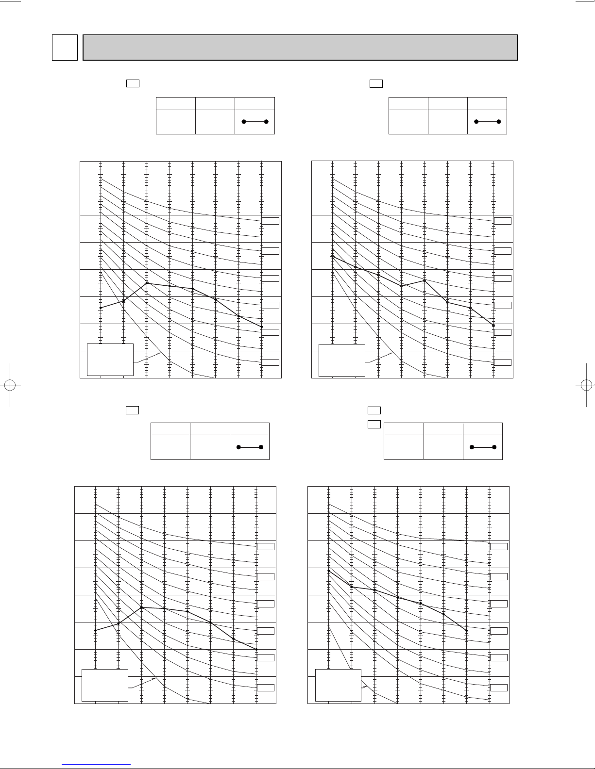
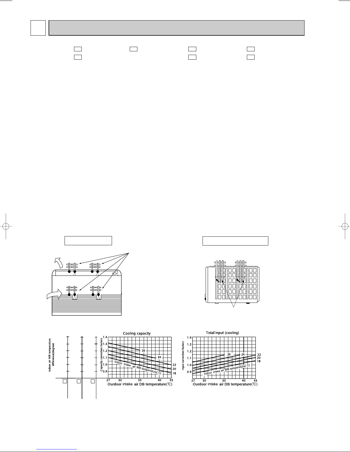
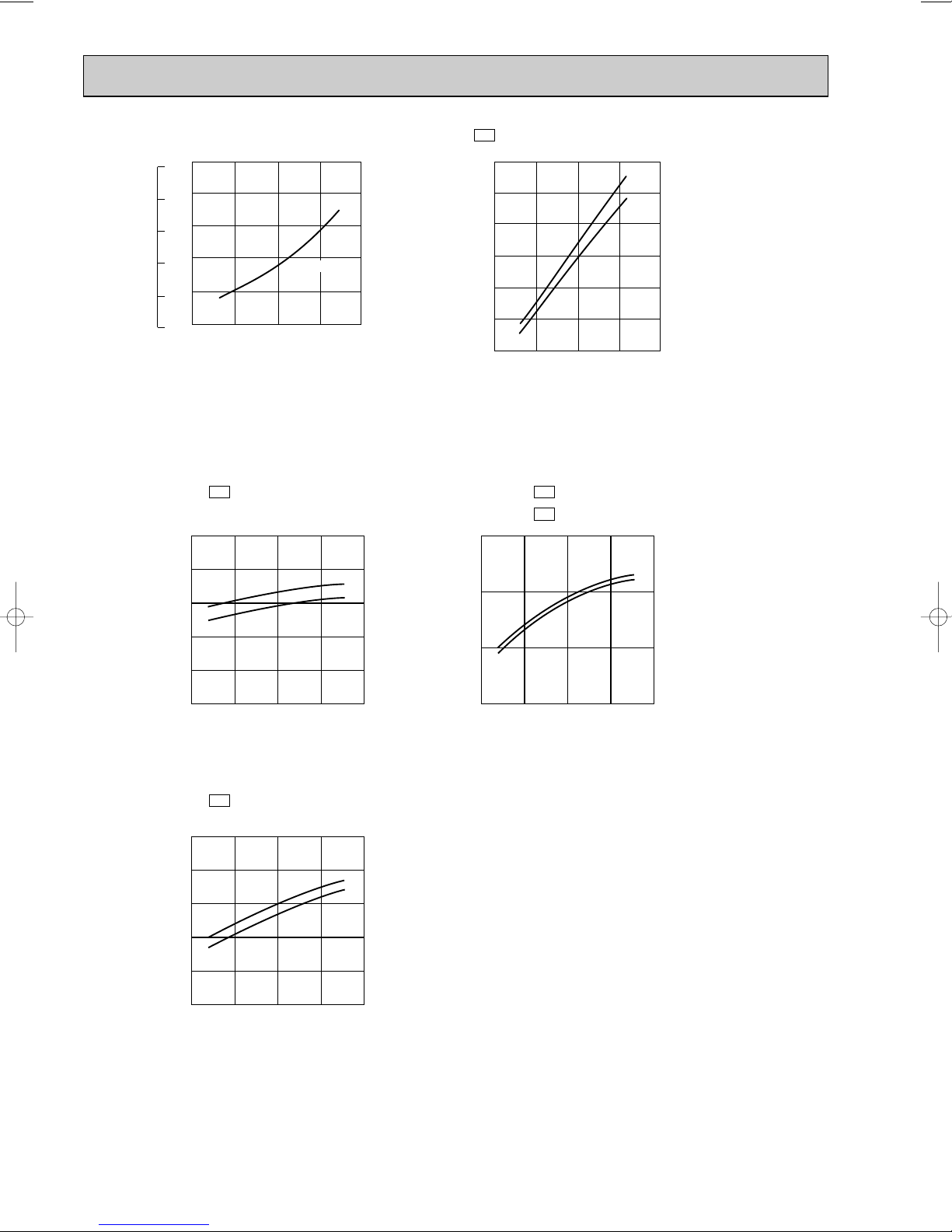
PERFORMANCE CURVES
MCFH-13NV - MCFH-24NV MCFH-18NV -
The standard data contained in these specifications apply only to the operation of the air conditioner under normal condition.
Operating conditions vary according to the areas where these units are installed. The following information has been provided
to clarify the operating characteristics of the air conditioner under the conditions indicated by the performance curve.
E3
E3E4
MUCFH-13NV - MUCFH-18NV MUCFH-18NV - MUCFH-24NV -
E4E4
E3E3
(1) GUARANTEED VOLTAGE
198~264V, 50Hz
(2) AIR FLOW
Air flow should be set at MAX.
(3) MAIN READINGS
COOLING
(1) Indoor intake air wet-bulb temperature : ˚CWB
(2) Indoor outlet air wet-bulb temperature : ˚CWB
(3) Outdoor intake air dry-bulb temperature : ˚CDB
(4) Total input : W
Indoor air wet/dry-bulb temperature difference on the left side of the chart on this page and next page shows the
difference between the indoor intake air wet/dry-bulb temperature and the indoor outlet air wet/dry-bulb temperature for
your reference at service.
HEATING
(1) Indoor intake air dry-bulb temperature : ˚CDB
(2) Indoor outlet air dry-bulb temperature : ˚CDB
(3) Outdoor intake air wet-bulb temperature : ˚CWB
(4) Total input : W
How to measure the indoor air wet-bulb/dry-bulb temperature difference
1. Attach at least 2 sets of wet and dry-bulb thermometers to the indoor air inlet as shown in the figure, and at least 2 sets of
wet and dry bulb thermometers to the indoor air outlet. The thermometers must be attached to the position where air speed
is high.
2. Attach at least 2 sets of wet and dry-bulb thermometers to the outdoor air inlet.
Cover the thermometers to prevent direct rays of the sun.
3. Check that the air filter is cleaned.
4. Open windows and doors of the room.
5. Press the EMERGENCY OPERATION switch once(twice) to start the EMERGENCY COOL(HEAT) MODE.
6. When system stabilizes after more than 15 minutes, measure temperature and take an average temperature.
7. 10 minutes later, measure temperature again and check that the temperature does not change.
INDOOR UNIT
11.7
10.7
9.7
8.7
7.8
6.9
14.7
13.4
12.1
10.9
9.7
8.5
MCFH-18NV- E3
9.3
8.6
7.8
7.1
6.3
5.6
MCFH-13NV- E4
OUTDOOR UNIT
MCFH-24NV- E3
16
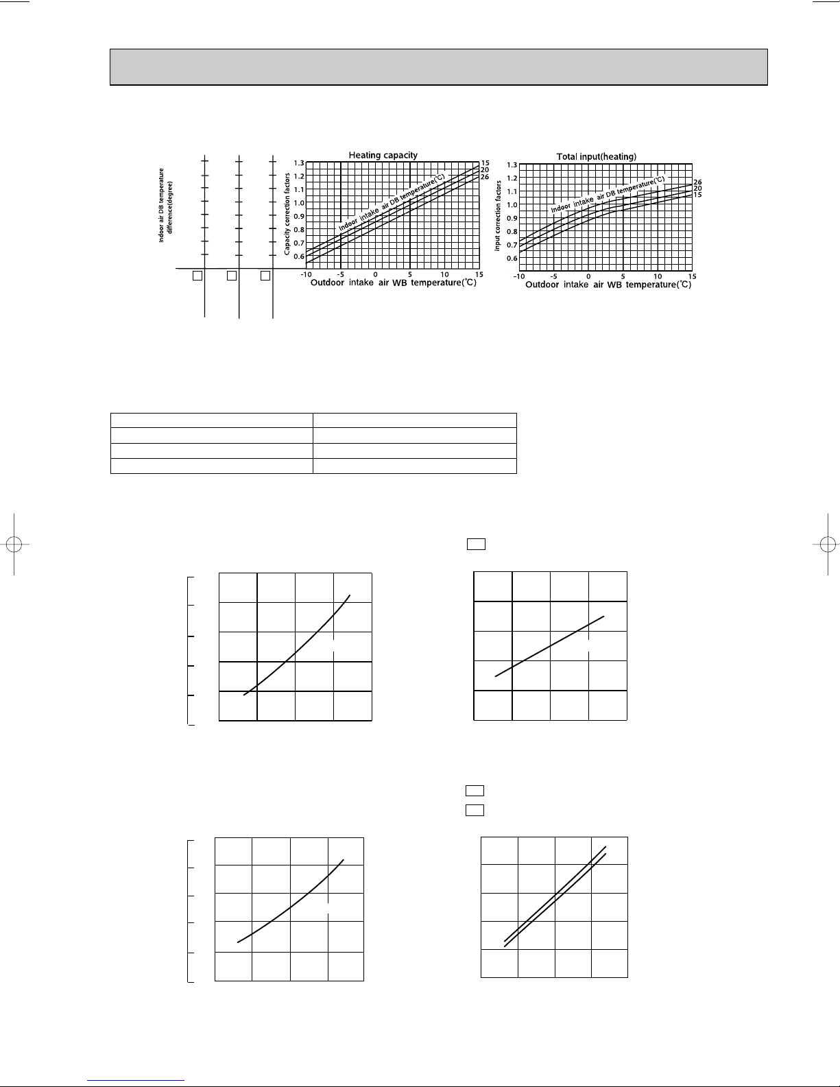
OUTDOOR LOW PRESSURE AND OUTDOOR UNIT CURRENT
18 32
50 60 70 (%)
Ambient temperature (:)
Ambient humidity (%)
Outdoor low pressure
50 60 70 (%)
Ambient temperature (:)
Ambient humidity (%)
Outdoor unit current (A)
(MPa [Gauge])
(kgf/F [Gauge])
15 20 25 30 35(:)
0.3
0.4
0.5
0.6
0.7
0.8
15 20 25 30 35(:)
3
4
5
6
7
8
220-240V 220-240V
18 32
7
8
5
6
4
3
0.7
0.6
0.5
0.4
0.3
0.2
15 18 20 25 30 32 35(:)
50 60 70 (%)
Ambient temperature (:)
Ambient humidity (%)
Outdoor low pressure
10
9
8
7
6
5
15 18 20 25 30 32 35(:)
50 60 70 (%)
Ambient temperature (:)
Ambient humidity (%)
Outdoor unit current (A)
240V
220V
7
6
4
3
2
5
220-240V
(MPa [Gauge])
(kgf/F [Gauge])
MCFH-18NV- E3
MCFH-13NV- E4
25.2
23.3
21.3
19.4
17.5
15.5
20.1
18.6
17.0
15.5
13.9
12.4
13.6
11.6
MCFH-24NV- E3
29.0
26.7
24.5
22.3
20.0
17.8
15.6
13.4
10.8
9.3
COOL operation
1 Both indoor and outdoor units are under the same temperature/humidity condition.
Dry Bulb temperature (˚C)
20
25
30
2 Air flow should be set at MAX..
3 The unit of pressure has been changed to MPa on the international system of units(SI unit system).
The conversion factor is : 1(MPa [Gauge]) =10.2(kgf/
Relative humidity (%)
50
60
70
ff
[Gauge])
MUCFH-13NV-
E4
MUCFH-18NVMUCFH-18NV-
17
E3
E4
(kgf/F [Gauge])
(MPa [Gauge])
0.7
7
0.6
6
0.5
5
0.4
4
0.3
3
Outdoor low pressure
0.2
2
15 18 20 25 30 32 35(:)
50 60 70 (%)
Ambient temperature (:)
Ambient humidity (%)
220-240V
HEAT operation
Condition Indoor : Dry bulb temerature 20.0:
Wet bulb temerature 14.5:
MUCFH-13NV-
E4
8
MUCFH-24NV-
Outdoor : Dry bulb temerature 7,15,20:
MUCFH-18NVMUCFH-18NV-
E3
13
12
11
10
9
Outdoor unit current (A)
8
7
15 18 20 25 30 32 35(:)
50 60 70 (%)
Ambient temperature (:)
Ambient humidity (%)
220V
240V
Wet bulb temerature 6,12,14.5:
E3
E4
10
7
6
5
4
Outdoor unit current (A)
3
5 7 10 15 20 25(:)
MUCFH-24NV-
14
13
12
11
10
Outdoor unit current (A)
9
5 7 10 15 20 25(:)
240V
220V
50 60 70 (%)
Ambient temperature (:)
Ambient humidity (%)
E4
240V
220V
50 60 70 (%)
Ambient temperature (:)
Ambient humidity (%)
9
8
Outdoor unit current (A)
7
5 7 10 15 20 25(:)
50 60 70 (%)
Ambient temperature (:)
Ambient humidity (%)
240V
220V
18
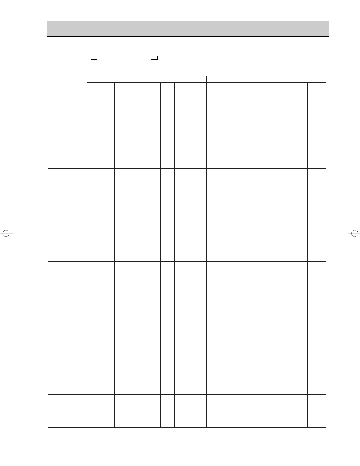
PERFORMANCE DATA COOL operation(220V)
MCFH-13NV - : MUCFH-13NV -
CAPACITY :3.7(KW) SHF :0.72 INPUT :1310(W)
INDOOR INDOOR
DB(:) WB(:)
21 18 4.35 2.35 0.54 1048 4.16 2.25 0.54 1100 4.00 2.16 0.54 1153 3.85 2.08 0.54 1205
21 20 4.53 1.90 0.42 1100 4.35 1.83 0.42 1166 4.22 1.77 0.42 1192 4.07 1.71 0.42 1245
22 18 4.35 2.52 0.58 1048 4.16 2.41 0.58 1100 4.00 2.32 0.58 1153 3.85 2.23 0.58 1205
22 20 4.53 2.08 0.46 1100 4.35 2.00 0.46 1166 4.22 1.94 0.46 1192 4.07 1.87 0.46 1245
22 22 4.72 1.60 0.34 1140 4.55 1.55 0.34 1212 4.44 1.51 0.34 1245 4.26 1.45 0.34 1297
23 18 4.35 2.70 0.62 1048 4.16 2.58 0.62 1100 4.00 2.48 0.62 1153 3.85 2.39 0.62 1205
23 20 4.53 2.27 0.50 1100 4.35 2.17 0.50 1166 4.22 2.11 0.50 1192 4.07 2.04 0.50 1245
23 22 4.72 1.79 0.38 1140 4.55 1.73 0.38 1212 4.44 1.69 0.38 1245 4.26 1.62 0.38 1297
24 18 4.35 2.87 0.66 1048 4.16 2.75 0.66 1100 4.00 2.64 0.66 1153 3.85 2.54 0.66 1205
24 20 4.53 2.45 0.54 1100 4.35 2.35 0.54 1166 4.22 2.28 0.54 1192 4.07 2.20 0.54 1245
24 22 4.72 1.98 0.42 1140 4.55 1.91 0.42 1212 4.44 1.86 0.42 1245 4.26 1.79 0.42 1297
24 24 4.96 1.49 0.30 1192 4.77 1.43 0.30 1258 4.66 1.40 0.30 1297 4.51 1.35 0.30 1362
25 18 4.35 3.04 0.70 1048 4.16 2.91 0.70 1100 4.00 2.80 0.70 1153 3.85 2.69 0.70 1205
25 20 4.53 2.63 0.58 1100 4.35 2.52 0.58 1166 4.22 2.45 0.58 1192 4.07 2.36 0.58 1245
25 22 4.72 2.17 0.46 1140 4.55 2.09 0.46 1212 4.44 2.04 0.46 1245 4.26 1.96 0.46 1297
25 24 4.96 1.69 0.34 1192 4.77 1.62 0.34 1258 4.66 1.59 0.34 1297 4.51 1.53 0.34 1362
26 18 4.35 3.22 0.74 1048 4.16 3.08 0.74 1100 4.00 2.96 0.74 1153 3.85 2.85 0.74 1205
26 20 4.53 2.81 0.62 1100 4.35 2.70 0.62 1166 4.22 2.62 0.62 1192 4.07 2.52 0.62 1245
26 22 4.72 2.36 0.50 1140 4.55 2.28 0.50 1212 4.44 2.22 0.50 1245 4.26 2.13 0.50 1297
26 24 4.96 1.88 0.38 1192 4.77 1.81 0.38 1258 4.66 1.77 0.38 1297 4.51 1.72 0.38 1362
26 26 5.11 1.33 0.26 1258 4.96 1.29 0.26 1323 4.88 1.27 0.26 1362 4.74 1.23 0.26 1402
27 18 4.35 3.39 0.78 1048 4.16 3.25 0.78 1100 4.00 3.12 0.78 1153 3.85 3.00 0.78 1205
27 20 4.53 2.99 0.66 1100 4.35 2.87 0.66 1166 4.22 2.78 0.66 1192 4.07 2.69 0.66 1245
27 22 4.72 2.55 0.54 1140 4.55 2.46 0.54 1212 4.44 2.40 0.54 1245 4.26 2.30 0.54 1297
27 24 4.96 2.08 0.42 1192 4.77 2.00 0.42 1258 4.66 1.96 0.42 1297 4.51 1.90 0.42 1362
27 26 5.11 1.53 0.30 1258 4.96 1.49 0.30 1323 4.88 1.47 0.30 1362 4.74 1.42 0.30 1402
28 18 4.35 3.56 0.82 1048 4.16 3.41 0.82 1100 4.00 3.28 0.82 1153 3.85 3.16 0.82 1205
28 20 4.53 3.17 0.70 1100 4.35 3.04 0.70 1166 4.22 2.95 0.70 1192 4.07 2.85 0.70 1245
28 22 4.72 2.74 0.58 1140 4.55 2.64 0.58 1212 4.44 2.58 0.58 1245 4.26 2.47 0.58 1297
28 24 4.96 2.28 0.46 1192 4.77 2.20 0.46 1258 4.66 2.14 0.46 1297 4.51 2.08 0.46 1362
28 26 5.11 1.74 0.34 1258 4.96 1.69 0.34 1323 4.88 1.66 0.34 1362 4.74 1.61 0.34 1402
29 18 4.35 3.74 0.86 1048 4.16 3.58 0.86 1100 4.00 3.44 0.86 1153 3.85 3.31 0.86 1205
29 20 4.53 3.35 0.74 1100 4.35 3.22 0.74 1166 4.22 3.12 0.74 1192 4.07 3.01 0.74 1245
29 22 4.72 2.92 0.62 1140 4.55 2.82 0.62 1212 4.44 2.75 0.62 1245 4.26 2.64 0.62 1297
29 24 4.96 2.48 0.50 1192 4.77 2.39 0.50 1258 4.66 2.33 0.50 1297 4.51 2.26 0.50 1362
29 26 5.11 1.94 0.38 1258 4.96 1.88 0.38 1323 4.88 1.86 0.38 1362 4.74 1.80 0.38 1402
30 18 4.35 3.91 0.90 1048 4.16 3.75 0.90 1100 4.00 3.60 0.90 1153 3.85 3.46 0.90 1205
30 20 4.53 3.54 0.78 1100 4.35 3.39 0.78 1166 4.22 3.29 0.78 1192 4.07 3.17 0.78 1245
30 22 4.72 3.11 0.66 1140 4.55 3.00 0.66 1212 4.44 2.93 0.66 1245 4.26 2.81 0.66 1297
30 24 4.96 2.68 0.54 1192 4.77 2.58 0.54 1258 4.66 2.52 0.54 1297 4.51 2.44 0.54 1362
30 26 5.11 2.14 0.42 1258 4.96 2.08 0.42 1323 4.88 2.05 0.42 1362 4.74 1.99 0.42 1402
31 18 4.35 4.09 0.94 1048 4.16 3.91 0.94 1100 4.00 3.76 0.94 1153 3.85 3.62 0.94 1205
31 20 4.53 3.72 0.82 1100 4.35 3.56 0.82 1166 4.22 3.46 0.82 1192 4.07 3.34 0.82 1245
31 22 4.72 3.30 0.70 1140 4.55 3.19 0.70 1212 4.44 3.11 0.70 1245 4.26 2.98 0.70 1297
31 24 4.96 2.88 0.58 1192 4.77 2.77 0.58 1258 4.66 2.70 0.58 1297 4.51 2.62 0.58 1362
31 26 5.11 2.35 0.46 1258 4.96 2.28 0.46 1323 4.88 2.25 0.46 1362 4.74 2.18 0.46 1402
32 18 4.35 4.26 0.98 1048 4.16 4.08 0.98 1100 4.00 3.92 0.98 1153 3.85 3.77 0.98 1205
32 20 4.53 3.90 0.86 1100 4.35 3.74 0.86 1166 4.22 3.63 0.86 1192 4.07 3.50 0.86 1245
32 22 4.72 3.49 0.74 1140 4.55 3.37 0.74 1212 4.44 3.29 0.74 1245 4.26 3.15 0.74 1297
32 24 4.96 3.07 0.62 1192 4.77 2.96 0.62 1258 4.66 2.89 0.62 1297 4.51 2.80 0.62 1362
32 26 5.11 2.55 0.50 1258 4.96 2.48 0.50 1323 4.88 2.44 0.50 1362 4.74 2.37 0.50 1402
NOTE Q : Total capacity (kW) SHF : Sensible heat factor DB : Dry-bulb temperature
SHC : Sensible heat capacity (kW) INPUT : Total power input (W) WB : Wet-bulb temperature
Q SHC SHF INPUT Q SHC SHF INPUT Q SHC SHF INPUT Q SHC SHF INPUT
21 25 27 30
E4E4
OUTDOOR DB(:)
19

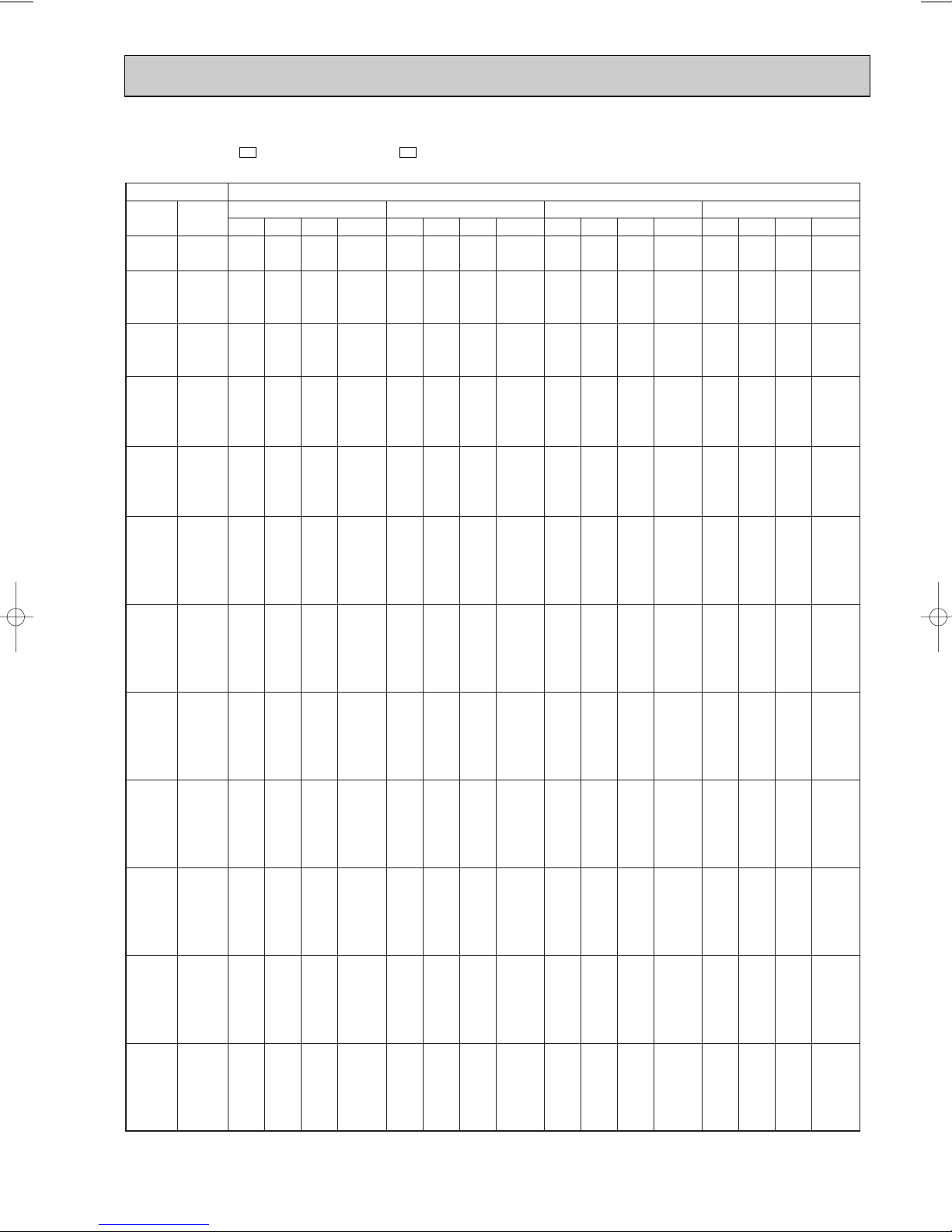
PERFORMANCE DATA COOL operation(220V)
MCFH-13NV - : MUCFH-13NV -
CAPACITY :3.7(KW) SHF :0.72 INPUT :1310(W)
INDOOR INDOOR
DB(:) WB(:)
21 18 3.63 1.96 0.54 1284 3.33 1.80 0.54 1362 3.20 1.73 0.54 1389 3.07 1.66 0.54 1415
21 20 3.81 1.60 0.42 1336 3.55 1.49 0.42 1402 3.42 1.44 0.42 1441 3.29 1.38 0.42 1480
22 18 3.63 2.10 0.58 1284 3.33 1.93 0.58 1362 3.20 1.86 0.58 1389 3.07 1.78 0.58 1415
22 20 3.81 1.75 0.46 1336 3.55 1.63 0.46 1402 3.42 1.57 0.46 1441 3.29 1.51 0.46 1480
22 22 4.03 1.37 0.34 1389 3.77 1.28 0.34 1467 3.64 1.24 0.34 1493 3.52 1.20 0.34 1520
23 18 3.63 2.25 0.62 1284 3.33 2.06 0.62 1362 3.20 1.98 0.62 1389 3.07 1.90 0.62 1415
23 20 3.81 1.91 0.50 1336 3.55 1.78 0.50 1402 3.42 1.71 0.50 1441 3.29 1.65 0.50 1480
23 22 4.03 1.53 0.38 1389 3.77 1.43 0.38 1467 3.64 1.38 0.38 1493 3.52 1.34 0.38 1520
24 18 3.63 2.39 0.66 1284 3.33 2.20 0.66 1362 3.20 2.11 0.66 1389 3.07 2.03 0.66 1415
24 20 3.81 2.06 0.54 1336 3.55 1.92 0.54 1402 3.42 1.85 0.54 1441 3.29 1.78 0.54 1480
24 22 4.03 1.69 0.42 1389 3.77 1.59 0.42 1467 3.64 1.53 0.42 1493 3.52 1.48 0.42 1520
24 24 4.26 1.28 0.30 1441 4.00 1.20 0.30 1507 3.89 1.17 0.30 1539 3.77 1.13 0.30 1572
25 18 3.63 2.54 0.70 1284 3.33 2.33 0.70 1362 3.20 2.24 0.70 1389 3.07 2.15 0.70 1415
25 20 3.81 2.21 0.58 1336 3.55 2.06 0.58 1402 3.42 1.99 0.58 1441 3.29 1.91 0.58 1480
25 22 4.03 1.86 0.46 1389 3.77 1.74 0.46 1467 3.64 1.68 0.46 1493 3.52 1.62 0.46 1520
25 24 4.26 1.45 0.34 1441 4.00 1.36 0.34 1507 3.89 1.32 0.34 1539 3.77 1.28 0.34 1572
26 18 3.63 2.68 0.74 1284 3.33 2.46 0.74 1362 3.20 2.37 0.74 1389 3.07 2.27 0.74 1415
26 20 3.81 2.36 0.62 1336 3.55 2.20 0.62 1402 3.42 2.12 0.62 1441 3.29 2.04 0.62 1480
26 22 4.03 2.02 0.50 1389 3.77 1.89 0.50 1467 3.64 1.82 0.50 1493 3.52 1.76 0.50 1520
26 24 4.26 1.62 0.38 1441 4.00 1.52 0.38 1507 3.89 1.48 0.38 1539 3.77 1.43 0.38 1572
26 26 4.48 1.16 0.26 1493 4.22 1.10 0.26 1559 4.09 1.06 0.26 1592 3.96 1.03 0.26 1624
27 18 3.63 2.83 0.78 1284 3.33 2.60 0.78 1362 3.20 2.50 0.78 1389 3.07 2.40 0.78 1415
27 20 3.81 2.52 0.66 1336 3.55 2.34 0.66 1402 3.42 2.26 0.66 1441 3.29 2.17 0.66 1480
27 22 4.03 2.18 0.54 1389 3.77 2.04 0.54 1467 3.64 1.97 0.54 1493 3.52 1.90 0.54 1520
27 24 4.26 1.79 0.42 1441 4.00 1.68 0.42 1507 3.89 1.63 0.42 1539 3.77 1.59 0.42 1572
27 26 4.48 1.34 0.30 1493 4.22 1.27 0.30 1559 4.09 1.23 0.30 1592 3.96 1.19 0.30 1624
28 18 3.63 2.97 0.82 1284 3.33 2.73 0.82 1362 3.20 2.62 0.82 1389 3.07 2.52 0.82 1415
28 20 3.81 2.67 0.70 1336 3.55 2.49 0.70 1402 3.42 2.40 0.70 1441 3.29 2.31 0.70 1480
28 22 4.03 2.34 0.58 1389 3.77 2.19 0.58 1467 3.64 2.11 0.58 1493 3.52 2.04 0.58 1520
28 24 4.26 1.96 0.46 1441 4.00 1.84 0.46 1507 3.89 1.79 0.46 1539 3.77 1.74 0.46 1572
28 26 4.48 1.52 0.34 1493 4.22 1.43 0.34 1559 4.09 1.39 0.34 1592 3.96 1.35 0.34 1624
29 18 3.63 3.12 0.86 1284 3.33 2.86 0.86 1362 3.20 2.75 0.86 1389 3.07 2.64 0.86 1415
29 20 3.81 2.82 0.74 1336 3.55 2.63 0.74 1402 3.42 2.53 0.74 1441 3.29 2.44 0.74 1480
29 22 4.03 2.50 0.62 1389 3.77 2.34 0.62 1467 3.64 2.26 0.62 1493 3.52 2.18 0.62 1520
29 24 4.26 2.13 0.50 1441 4.00 2.00 0.50 1507 3.89 1.94 0.50 1539 3.77 1.89 0.50 1572
29 26 4.48 1.70 0.38 1493 4.22 1.60 0.38 1559 4.09 1.55 0.38 1592 3.96 1.50 0.38 1624
30 18 3.63 3.26 0.90 1284 3.33 3.00 0.90 1362 3.20 2.88 0.90 1389 3.07 2.76 0.90 1415
30 20 3.81 2.97 0.78 1336 3.55 2.77 0.78 1402 3.42 2.67 0.78 1441 3.29 2.57 0.78 1480
30 22 4.03 2.66 0.66 1389 3.77 2.49 0.66 1467 3.64 2.41 0.66 1493 3.52 2.32 0.66 1520
30 24 4.26 2.30 0.54 1441 4.00 2.16 0.54 1507 3.89 2.10 0.54 1539 3.77 2.04 0.54 1572
30 26 4.48 1.88 0.42 1493 4.22 1.77 0.42 1559 4.09 1.72 0.42 1592 3.96 1.66 0.42 1624
31 18 3.63 3.41 0.94 1284 3.33 3.13 0.94 1362 3.20 3.01 0.94 1389 3.07 2.89 0.94 1415
31 20 3.81 3.13 0.82 1336 3.55 2.91 0.82 1402 3.42 2.81 0.82 1441 3.29 2.70 0.82 1480
31 22 4.03 2.82 0.70 1389 3.77 2.64 0.70 1467 3.64 2.55 0.70 1493 3.52 2.46 0.70 1520
31 24 4.26 2.47 0.58 1441 4.00 2.32 0.58 1507 3.89 2.25 0.58 1539 3.77 2.19 0.58 1572
31 26 4.48 2.06 0.46 1493 4.22 1.94 0.46 1559 4.09 1.88 0.46 1592 3.96 1.82 0.46 1624
32 18 3.63 3.55 0.98 1284 3.33 3.26 0.98 1362 3.20 3.14 0.98 1389 3.07 3.01 0.98 1415
32 20 3.81 3.28 0.86 1336 3.55 3.05 0.86 1402 3.42 2.94 0.86 1441 3.29 2.83 0.86 1480
32 22 4.03 2.98 0.74 1389 3.77 2.79 0.74 1467 3.64 2.70 0.74 1493 3.52 2.60 0.74 1520
32 24 4.26 2.64 0.62 1441 4.00 2.48 0.62 1507 3.89 2.41 0.62 1539 3.77 2.34 0.62 1572
32 26 4.48 2.24 0.50 1493 4.22 2.11 0.50 1559 4.09 2.04 0.50 1592 3.96 1.98 0.50 1624
NOTE Q : Total capacity (kW) SHF : Sensible heat factor DB : Dry-bulb temperature
SHC : Sensible heat capacity (kW) INPUT : Total power input (W) WB : Wet-bulb temperature
Q SHC SHF INPUT Q SHC SHF INPUT Q SHC SHF INPUT Q SHC SHF INPUT
35 40 43 46
E4E4
OUTDOOR DB(:)
20
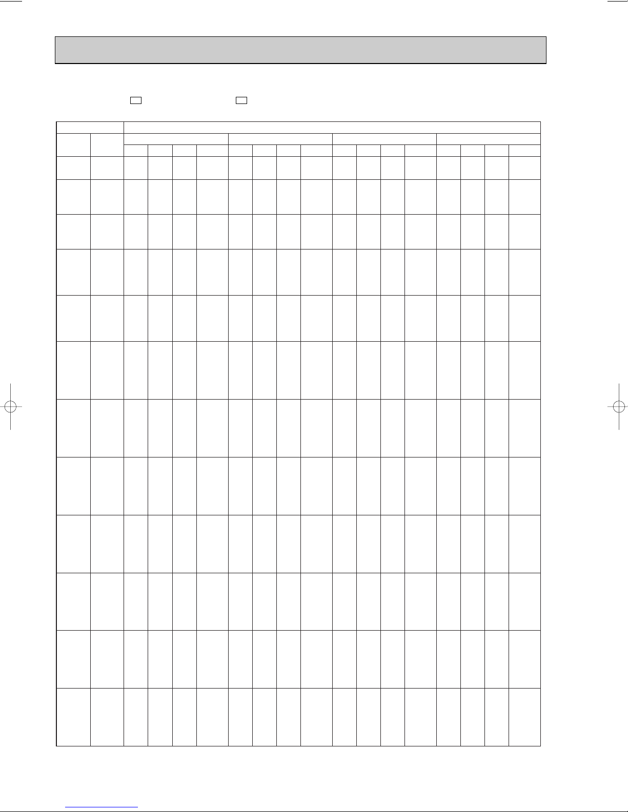
PERFORMANCE DATA COOL operation(240V)
MCFH-13NV - : MUCFH-13NV -
CAPACITY :3.7(KW) SHF :0.72 INPUT :1400(W)
INDOOR INDOOR
DB(:) WB(:)
21 18 4.35 2.35 0.54 1120 4.16 2.25 0.54 1176 4.00 2.16 0.54 1232 3.85 2.08 0.54 1288
21 20 4.53 1.90 0.42 1176 4.35 1.83 0.42 1246 4.22 1.77 0.42 1274 4.07 1.71 0.42 1330
22 18 4.35 2.52 0.58 1120 4.16 2.41 0.58 1176 4.00 2.32 0.58 1232 3.85 2.23 0.58 1288
22 20 4.53 2.08 0.46 1176 4.35 2.00 0.46 1246 4.22 1.94 0.46 1274 4.07 1.87 0.46 1330
22 22 4.72 1.60 0.34 1218 4.55 1.55 0.34 1295 4.44 1.51 0.34 1330 4.26 1.45 0.34 1386
23 18 4.35 2.70 0.62 1120 4.16 2.58 0.62 1176 4.00 2.48 0.62 1232 3.85 2.39 0.62 1288
23 20 4.53 2.27 0.50 1176 4.35 2.17 0.50 1246 4.22 2.11 0.50 1274 4.07 2.04 0.50 1330
23 22 4.72 1.79 0.38 1218 4.55 1.73 0.38 1295 4.44 1.69 0.38 1330 4.26 1.62 0.38 1386
24 18 4.35 2.87 0.66 1120 4.16 2.75 0.66 1176 4.00 2.64 0.66 1232 3.85 2.54 0.66 1288
24 20 4.53 2.45 0.54 1176 4.35 2.35 0.54 1246 4.22 2.28 0.54 1274 4.07 2.20 0.54 1330
24 22 4.72 1.98 0.42 1218 4.55 1.91 0.42 1295 4.44 1.86 0.42 1330 4.26 1.79 0.42 1386
24 24 4.96 1.49 0.30 1274 4.77 1.43 0.30 1344 4.66 1.40 0.30 1386 4.51 1.35 0.30 1456
25 18 4.35 3.04 0.70 1120 4.16 2.91 0.70 1176 4.00 2.80 0.70 1232 3.85 2.69 0.70 1288
25 20 4.53 2.63 0.58 1176 4.35 2.52 0.58 1246 4.22 2.45 0.58 1274 4.07 2.36 0.58 1330
25 22 4.72 2.17 0.46 1218 4.55 2.09 0.46 1295 4.44 2.04 0.46 1330 4.26 1.96 0.46 1386
25 24 4.96 1.69 0.34 1274 4.77 1.62 0.34 1344 4.66 1.59 0.34 1386 4.51 1.53 0.34 1456
26 18 4.35 3.22 0.74 1120 4.16 3.08 0.74 1176 4.00 2.96 0.74 1232 3.85 2.85 0.74 1288
26 20 4.53 2.81 0.62 1176 4.35 2.70 0.62 1246 4.22 2.62 0.62 1274 4.07 2.52 0.62 1330
26 22 4.72 2.36 0.50 1218 4.55 2.28 0.50 1295 4.44 2.22 0.50 1330 4.26 2.13 0.50 1386
26 24 4.96 1.88 0.38 1274 4.77 1.81 0.38 1344 4.66 1.77 0.38 1386 4.51 1.72 0.38 1456
26 26 5.11 1.33 0.26 1344 4.96 1.29 0.26 1414 4.88 1.27 0.26 1456 4.74 1.23 0.26 1498
27 18 4.35 3.39 0.78 1120 4.16 3.25 0.78 1176 4.00 3.12 0.78 1232 3.85 3.00 0.78 1288
27 20 4.53 2.99 0.66 1176 4.35 2.87 0.66 1246 4.22 2.78 0.66 1274 4.07 2.69 0.66 1330
27 22 4.72 2.55 0.54 1218 4.55 2.46 0.54 1295 4.44 2.40 0.54 1330 4.26 2.30 0.54 1386
27 24 4.96 2.08 0.42 1274 4.77 2.00 0.42 1344 4.66 1.96 0.42 1386 4.51 1.90 0.42 1456
27 26 5.11 1.53 0.30 1344 4.96 1.49 0.30 1414 4.88 1.47 0.30 1456 4.74 1.42 0.30 1498
28 18 4.35 3.56 0.82 1120 4.16 3.41 0.82 1176 4.00 3.28 0.82 1232 3.85 3.16 0.82 1288
28 20 4.53 3.17 0.70 1176 4.35 3.04 0.70 1246 4.22 2.95 0.70 1274 4.07 2.85 0.70 1330
28 22 4.72 2.74 0.58 1218 4.55 2.64 0.58 1295 4.44 2.58 0.58 1330 4.26 2.47 0.58 1386
28 24 4.96 2.28 0.46 1274 4.77 2.20 0.46 1344 4.66 2.14 0.46 1386 4.51 2.08 0.46 1456
28 26 5.11 1.74 0.34 1344 4.96 1.69 0.34 1414 4.88 1.66 0.34 1456 4.74 1.61 0.34 1498
29 18 4.35 3.74 0.86 1120 4.16 3.58 0.86 1176 4.00 3.44 0.86 1232 3.85 3.31 0.86 1288
29 20 4.53 3.35 0.74 1176 4.35 3.22 0.74 1246 4.22 3.12 0.74 1274 4.07 3.01 0.74 1330
29 22 4.72 2.92 0.62 1218 4.55 2.82 0.62 1295 4.44 2.75 0.62 1330 4.26 2.64 0.62 1386
29 24 4.96 2.48 0.50 1274 4.77 2.39 0.50 1344 4.66 2.33 0.50 1386 4.51 2.26 0.50 1456
29 26 5.11 1.94 0.38 1344 4.96 1.88 0.38 1414 4.88 1.86 0.38 1456 4.74 1.80 0.38 1498
30 18 4.35 3.91 0.90 1120 4.16 3.75 0.90 1176 4.00 3.60 0.90 1232 3.85 3.46 0.90 1288
30 20 4.53 3.54 0.78 1176 4.35 3.39 0.78 1246 4.22 3.29 0.78 1274 4.07 3.17 0.78 1330
30 22 4.72 3.11 0.66 1218 4.55 3.00 0.66 1295 4.44 2.93 0.66 1330 4.26 2.81 0.66 1386
30 24 4.96 2.68 0.54 1274 4.77 2.58 0.54 1344 4.66 2.52 0.54 1386 4.51 2.44 0.54 1456
30 26 5.11 2.14 0.42 1344 4.96 2.08 0.42 1414 4.88 2.05 0.42 1456 4.74 1.99 0.42 1498
31 18 4.35 4.09 0.94 1120 4.16 3.91 0.94 1176 4.00 3.76 0.94 1232 3.85 3.62 0.94 1288
31 20 4.53 3.72 0.82 1176 4.35 3.56 0.82 1246 4.22 3.46 0.82 1274 4.07 3.34 0.82 1330
31 22 4.72 3.30 0.70 1218 4.55 3.19 0.70 1295 4.44 3.11 0.70 1330 4.26 2.98 0.70 1386
31 24 4.96 2.88 0.58 1274 4.77 2.77 0.58 1344 4.66 2.70 0.58 1386 4.51 2.62 0.58 1456
31 26 5.11 2.35 0.46 1344 4.96 2.28 0.46 1414 4.88 2.25 0.46 1456 4.74 2.18 0.46 1498
32 18 4.35 4.26 0.98 1120 4.16 4.08 0.98 1176 4.00 3.92 0.98 1232 3.85 3.77 0.98 1288
32 20 4.53 3.90 0.86 1176 4.35 3.74 0.86 1246 4.22 3.63 0.86 1274 4.07 3.50 0.86 1330
32 22 4.72 3.49 0.74 1218 4.55 3.37 0.74 1295 4.44 3.29 0.74 1330 4.26 3.15 0.74 1386
32 24 4.96 3.07 0.62 1274 4.77 2.96 0.62 1344 4.66 2.89 0.62 1386 4.51 2.80 0.62 1456
32 26 5.11 2.55 0.50 1344 4.96 2.48 0.50 1414 4.88 2.44 0.50 1456 4.74 2.37 0.50 1498
NOTE Q : Total capacity (kW) SHF : Sensible heat factor DB : Dry-bulb temperature
SHC : Sensible heat capacity (kW) INPUT : Total power input (W) WB : Wet-bulb temperature
Q SHC SHF INPUT Q SHC SHF INPUT Q SHC SHF INPUT Q SHC SHF INPUT
21 25 27 30
E4E4
OUTDOOR DB(:)
21
PERFORMANCE DATA COOL operation(240V)
MCFH-13NV - : MUCFH-13NV -
CAPACITY :3.7(KW) SHF :0.72 INPUT :1400(W)
INDOOR INDOOR
DB(:) WB(:)
21 18 3.63 1.96 0.54 1372 3.33 1.80 0.54 1456 3.20 1.73 0.54 1484 3.07 1.66 0.54 1512
21 20 3.81 1.60 0.42 1428 3.55 1.49 0.42 1498 3.42 1.44 0.42 1540 3.29 1.38 0.42 1582
22 18 3.63 2.10 0.58 1372 3.33 1.93 0.58 1456 3.20 1.86 0.58 1484 3.07 1.78 0.58 1512
22 20 3.81 1.75 0.46 1428 3.55 1.63 0.46 1498 3.42 1.57 0.46 1540 3.29 1.51 0.46 1582
22 22 4.03 1.37 0.34 1484 3.77 1.28 0.34 1568 3.64 1.24 0.34 1596 3.52 1.20 0.34 1624
23 18 3.63 2.25 0.62 1372 3.33 2.06 0.62 1456 3.20 1.98 0.62 1484 3.07 1.90 0.62 1512
23 20 3.81 1.91 0.50 1428 3.55 1.78 0.50 1498 3.42 1.71 0.50 1540 3.29 1.65 0.50 1582
23 22 4.03 1.53 0.38 1484 3.77 1.43 0.38 1568 3.64 1.38 0.38 1596 3.52 1.34 0.38 1624
24 18 3.63 2.39 0.66 1372 3.33 2.20 0.66 1456 3.20 2.11 0.66 1484 3.07 2.03 0.66 1512
24 20 3.81 2.06 0.54 1428 3.55 1.92 0.54 1498 3.42 1.85 0.54 1540 3.29 1.78 0.54 1582
24 22 4.03 1.69 0.42 1484 3.77 1.59 0.42 1568 3.64 1.53 0.42 1596 3.52 1.48 0.42 1624
24 24 4.26 1.28 0.30 1540 4.00 1.20 0.30 1610 3.89 1.17 0.30 1645 3.77 1.13 0.30 1680
25 18 3.63 2.54 0.70 1372 3.33 2.33 0.70 1456 3.20 2.24 0.70 1484 3.07 2.15 0.70 1512
25 20 3.81 2.21 0.58 1428 3.55 2.06 0.58 1498 3.42 1.99 0.58 1540 3.29 1.91 0.58 1582
25 22 4.03 1.86 0.46 1484 3.77 1.74 0.46 1568 3.64 1.68 0.46 1596 3.52 1.62 0.46 1624
25 24 4.26 1.45 0.34 1540 4.00 1.36 0.34 1610 3.89 1.32 0.34 1645 3.77 1.28 0.34 1680
26 18 3.63 2.68 0.74 1372 3.33 2.46 0.74 1456 3.20 2.37 0.74 1484 3.07 2.27 0.74 1512
26 20 3.81 2.36 0.62 1428 3.55 2.20 0.62 1498 3.42 2.12 0.62 1540 3.29 2.04 0.62 1582
26 22 4.03 2.02 0.50 1484 3.77 1.89 0.50 1568 3.64 1.82 0.50 1596 3.52 1.76 0.50 1624
26 24 4.26 1.62 0.38 1540 4.00 1.52 0.38 1610 3.89 1.48 0.38 1645 3.77 1.43 0.38 1680
26 26 4.48 1.16 0.26 1596 4.22 1.10 0.26 1666 4.09 1.06 0.26 1701 3.96 1.03 0.26 1736
27 18 3.63 2.83 0.78 1372 3.33 2.60 0.78 1456 3.20 2.50 0.78 1484 3.07 2.40 0.78 1512
27 20 3.81 2.52 0.66 1428 3.55 2.34 0.66 1498 3.42 2.26 0.66 1540 3.29 2.17 0.66 1582
27 22 4.03 2.18 0.54 1484 3.77 2.04 0.54 1568 3.64 1.97 0.54 1596 3.52 1.90 0.54 1624
27 24 4.26 1.79 0.42 1540 4.00 1.68 0.42 1610 3.89 1.63 0.42 1645 3.77 1.59 0.42 1680
27 26 4.48 1.34 0.30 1596 4.22 1.27 0.30 1666 4.09 1.23 0.30 1701 3.96 1.19 0.30 1736
28 18 3.63 2.97 0.82 1372 3.33 2.73 0.82 1456 3.20 2.62 0.82 1484 3.07 2.52 0.82 1512
28 20 3.81 2.67 0.70 1428 3.55 2.49 0.70 1498 3.42 2.40 0.70 1540 3.29 2.31 0.70 1582
28 22 4.03 2.34 0.58 1484 3.77 2.19 0.58 1568 3.64 2.11 0.58 1596 3.52 2.04 0.58 1624
28 24 4.26 1.96 0.46 1540 4.00 1.84 0.46 1610 3.89 1.79 0.46 1645 3.77 1.74 0.46 1680
28 26 4.48 1.52 0.34 1596 4.22 1.43 0.34 1666 4.09 1.39 0.34 1701 3.96 1.35 0.34 1736
29 18 3.63 3.12 0.86 1372 3.33 2.86 0.86 1456 3.20 2.75 0.86 1484 3.07 2.64 0.86 1512
29 20 3.81 2.82 0.74 1428 3.55 2.63 0.74 1498 3.42 2.53 0.74 1540 3.29 2.44 0.74 1582
29 22 4.03 2.50 0.62 1484 3.77 2.34 0.62 1568 3.64 2.26 0.62 1596 3.52 2.18 0.62 1624
29 24 4.26 2.13 0.50 1540 4.00 2.00 0.50 1610 3.89 1.94 0.50 1645 3.77 1.89 0.50 1680
29 26 4.48 1.70 0.38 1596 4.22 1.60 0.38 1666 4.09 1.55 0.38 1701 3.96 1.50 0.38 1736
30 18 3.63 3.26 0.90 1372 3.33 3.00 0.90 1456 3.20 2.88 0.90 1484 3.07 2.76 0.90 1512
30 20 3.81 2.97 0.78 1428 3.55 2.77 0.78 1498 3.42 2.67 0.78 1540 3.29 2.57 0.78 1582
30 22 4.03 2.66 0.66 1484 3.77 2.49 0.66 1568 3.64 2.41 0.66 1596 3.52 2.32 0.66 1624
30 24 4.26 2.30 0.54 1540 4.00 2.16 0.54 1610 3.89 2.10 0.54 1645 3.77 2.04 0.54 1680
30 26 4.48 1.88 0.42 1596 4.22 1.77 0.42 1666 4.09 1.72 0.42 1701 3.96 1.66 0.42 1736
31 18 3.63 3.41 0.94 1372 3.33 3.13 0.94 1456 3.20 3.01 0.94 1484 3.07 2.89 0.94 1512
31 20 3.81 3.13 0.82 1428 3.55 2.91 0.82 1498 3.42 2.81 0.82 1540 3.29 2.70 0.82 1582
31 22 4.03 2.82 0.70 1484 3.77 2.64 0.70 1568 3.64 2.55 0.70 1596 3.52 2.46 0.70 1624
31 24 4.26 2.47 0.58 1540 4.00 2.32 0.58 1610 3.89 2.25 0.58 1645 3.77 2.19 0.58 1680
31 26 4.48 2.06 0.46 1596 4.22 1.94 0.46 1666 4.09 1.88 0.46 1701 3.96 1.82 0.46 1736
32 18 3.63 3.55 0.98 1372 3.33 3.26 0.98 1456 3.20 3.14 0.98 1484 3.07 3.01 0.98 1512
32 20 3.81 3.28 0.86 1428 3.55 3.05 0.86 1498 3.42 2.94 0.86 1540 3.29 2.83 0.86 1582
32 22 4.03 2.98 0.74 1484 3.77 2.79 0.74 1568 3.64 2.70 0.74 1596 3.52 2.60 0.74 1624
32 24 4.26 2.64 0.62 1540 4.00 2.48 0.62 1610 3.89 2.41 0.62 1645 3.77 2.34 0.62 1680
32 26 4.48 2.24 0.50 1596 4.22 2.11 0.50 1666 4.09 2.04 0.50 1701 3.96 1.98 0.50 1736
NOTE Q : Total capacity (kW) SHF : Sensible heat factor DB : Dry-bulb temperature
SHC : Sensible heat capacity (kW) INPUT : Total power input (W) WB : Wet-bulb temperature
Q SHC SHF INPUT Q SHC SHF INPUT Q SHC SHF INPUT Q SHC SHF INPUT
35 40 43 46
E4E4
OUTDOOR DB(:)
22
 Loading...