

Page 1
SPLIT-TYPE AIR CONDITIONERS
SERVICE MANUAL
Wireless type
Models
Revision:
● MS09NW2, MS12NN2, MS15NN2 and
MS17NN2 has been added.
● Parts List has been partially modified.
● Please void OB192 REVISED EDITION -A.
No. OB192
REVISED EDITION -B
MS09NW
MS12NN
MS15NN
MS17NN
MS09NW2
MS12NN2
MS15NN2
MS17NN2
MS12NN MS12NN2
MS15NN MS15NN2
MS17NN MS17NN2
INDOOR UNIT
MU12NN MU12NN2
MU15NN MU15NN2
MU17NN MU17NN2
OUTDOOR UNIT
(W)
· MU09NW MUM30NN
(W)
· MU12NN MUM30NN2
(W)
· MU15NN
(W)
· MU17NN
(W)
· MU09NW2
(W)
· MU12NN2
(W)
· MU15NN2
(W)
· MU17NN2
CONTENTS
1. FEATURES ························································2
2.TECHNICAL CHANGES ····································4
3. PART NAMES AND FUNCTIONS······················5
4. SPECIFICATIONS ··············································7
5. DATA ································································12
Remote
controller
6. OUTLINES AND DIMENSIONS ······················23
7. W IRING DIAGRAM ··········································26
8. REFRIGERANT SYSTEM DIAGRAM··············32
9. MICROPROCESSOR CONTROL ····················35
10. SERVICE FUNCTIONS ····································43
11. TROUBLESHOOTING ······································44
12. DISASSEMBLY INSTRUCTIONS ····················59
13. PARTS LIST······················································70
14. OPTIONAL PARTS ··········································7 9
The Slim Line.
From Mitsubishi Electric.
Refer to our Service Manual OB202 when the
indoor unit is used in the multi-system operation.
Applied models are MS09NW and MS15NN.
L
R
D
I
S
E
T
Page 2
Revision:
●The following parts numbers have been modified.
1. OUTDOOR P.C. BOARD of MUM30NN (T2W 800 451 ➔ T2W E46 451)
2. SURGE KILLER of MUM30NN (T2W E64 410 has been added)
3. CAPILLARY TUBE (for 09A, 09B) of MUM30NN (M21 463 936 ➔ M21 195 936) (See REFRIGERANT SYSTEM)
4. CAPILLARY TUBE (for 15C) of MUM30NN (M21 987 936 ➔ M21 G46 936) (See REFRIGERANT SYSTEM)
5. CAPILLARY TUBE (for 09A, 09B) of MUM30NN2 (M21 463 936 ➔ M21 AP9 936) (See REFRIGERANT SYSTEM)
6. CAPILLARY TUBE (for 15C) of MUM30NN2 (M21 987 936 ➔ M21 G46 936) (See REFRIGERANT SYSTEM)
7. HIGH PRESSURE SWITCH of MUM30NN2 (Q’ty/unit 1 ➔ 3)
8. MC1. MC2. CAPACITOR of MUM30NN2 (T2W 738 353 ➔ T2W 903 353)
●Please void OB192REVISED EDITION -B.
1
MS09NW MS09NW2 8,500Btu/h 10.2
MS12NN MS12NN2 12,300/12,600Btu/h 11.3/11.3
MS15NN MS15NN2 14,300/14,600Btu/h 10.5/10.5
MS17NN MS17NN2 15,900/16,100Btu/h 10.2/10.2
FEATURES
LCD wireless
MS12NN MS15NN MS17NN
MS12NN2 MS15NN2 MS17NN2
Models Cooling capacity SEER
remote controller
MU12NN MU15NN MU17NN
MU12NN2 MU15NN2 MU17NN2
NEW “I FEEL CONTROL” IN OUR LCD WIRELESS REMOTE CONTROLLER WITH ON/OFF PROGRAM
TIMER
Mitsubishi Electric’s new wireless remote controller incorporates a number of advanced features that provide even greater con-
trol and ease-to- use. It has a liquid crystal display which indicates such information as mode, fan speed and temperature
selected as well as the programmed ON/OFF time.It is also equipped with “I Feel Control”, a unique Mitsubishi Electric feature
that allows the user to adjust the temperature to exactly the level he or she wants simply by tapping the button that describes
present conditions : “Too Cool” or “Too Warm”.The optimum temperature set this way is then memorized for immediate recall
whenever the air conditioner is used again.And what’s more, the new controller has been redesigned and easier to handle
than before.
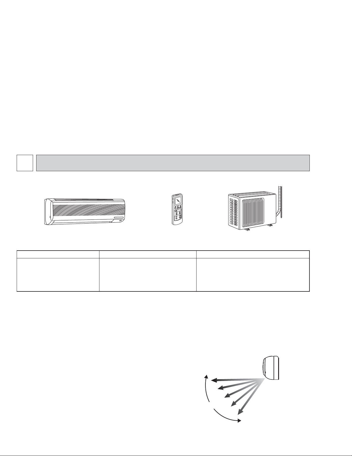
Select desired air flow direction.
REMOTE-CONTROL OPERATION MODE
Using the remote controller, you can select from five airflow set-
tings to match room layout and the location of people.Also, you
can set the vane to swing automatically.
SWING
2
Page 3
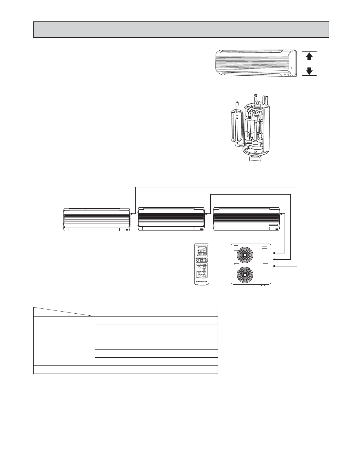
Small in size, big on cooling.
COMPACT INDOOR UNIT
The sleek design of the NW/NN Series matches virtually any room
13
layout.For instance, MS09 is 10
which used to be 14
3
/16o 311/8o 53/8.
/16o 321/16o 73/16(Ho W o D),
1013/16
MS09NW MS09NW2
AUTO-RESTART FUNCTION
The auto restart function restar ts the equipment when power is
restored following an outage automatically. Operation resumes in
the mode in which the equipment was running immediately before
the outage.
HIGH PERFORMANCE ROTARY COMPRESSOR
The advanced design of Mitsubishi Electric’s powerful and energy
efficient rotary compressor results in lower operating costs and
longer service life.
MSM30NN MSM30NN2
This “3 to 1” Multi system (MSM30NN / MSM30NN2) consists of a single outdoor unit with three compressors that permit up to three indoor units to be installed separate rooms, each with its own controller.
MS09NW (A)
Cooling Capacity (BTU/h)
Operation
Indoor unit
1 Indoor Unit Operation
2 Indoor Unit Operation
3 Indoor Unit Operation
MS09NW
8,200
—
—
8,200
8,200
—
8,100
MS09NW (B)
MS09NW
—
8,200
—
8,200
—
8,200
8,100
LCD Wireless
remote controller
MS15NN
—
—
12,400
—
12,400
12,400
12,200
MS15NN (C)
MUM30NN
MUM30NN2
SPACE-SAVING LAYOUT
Two or three indoor units are served by a single outdoor unit whose installation requires only minimum space. This allows
equipment installed outside the house to be arranged in a neat, space-saving layout.
FLEXIBLE INSTALLATION OF INDOOR UNITS
Each indoor unit can be connected to piping up to 65 feet in length, providing plenty of freedom in determining the best locations for installation.
3
Page 4

2
➔
TECHNICAL CHANGES
MS09EW➔ MS09NW
1. Indoor unit has been changed.
(Outline dimension changes. 31-1/8” o 5-3/8” o 14-3/16”(W o Do H)➔32-1/16” o 7-3/16” o 10-13/16(W o D o H)
2. Outdoor unit has been changed.
(Outline dimension changes. 29-15/16” o 9-1/16” o 21-1/4”(W o Do H)➔30-11/16” o 10-1/16” o 21-1/4”(W o D o H))
(Capillary tube, refrigerant and pipe had changed.)
3. Remote controller has been changed. (The timer function was changed to the clock timer function.)
4. Indoor auto vane has been adopted.
MS12EN, MS15EN ➔ MS12NN, MS15NN
1. Indoor unit has been changed.
(Outline dimension changes. 39-3/8” o 7” o 14-3/16”(W o Do H)➔39-15/16” o 7-1/2” o 12-5/8”(W o D o H))
2. Outdoor unit has been changed.
(Outline dimension changes. 33-1/2” o 11-7/16” o 23-7/8”(W o Do H)➔33-7/16” o 11-7/16” o 23-13/16”(W o D o H))
(Capillary tube, refrigerant and pipe had changed.)
3. Remote controller has been changed. (The timer function was changed to the clock timer function.)
4.The swing mode has been added to indoor auto vane.
MSM30EN2➔ MSM30NN
1. Indoor unit has been changed.
2. Outdoor unit has been changed.
3. Remote controller has been changed. (The timer function was changed to the clock timer function.)
4.The swing mode has been added to indoor auto vane.
5. Outdoor unit fan speed control has been changed.(MF1/MF2 : 1.Lo/Lo➔Stop/Hi 2.Me/Me➔Me/Me 3.Hi/Hi➔Hi/Hi)
6.The relay “X64” has been added to electric circuit.
7. Surge absorber has been added to electric circuit.
MSM30NN➔ MSM30NN2
1. Outdoor unit has changed.
2. Compressor has changed. (Compressor A,B: KH122WEV➔KH122WES)
3. Outdoor unit fan speed control has changed.(MF1/MF2 : 1.Stop/Hi➔Lo/Lo 2.Me/Me➔Lo/Lo 3.Hi/Hi➔Hi/Hi)
4.Wiring diagram has been changed.
5. Capillar y tube has been changed.
6. Accumulator has been enlarged.(Refrigerant cycle A and B)
7. High-pressure switch has been added.
8. Outdoor unit heat exchanger has changed.
MS09NW➔ MS09NW2
MS12NN MS15NN MS17NN
1. Power supplied way has changed from “supply to both indoor and outdoor” to “supply to only outdoor”. (“Supply to both
indoor and outdoor” as before is also possible.)
2. Remote controller has changed.
(•The timer function has changed from program timer to ON/OFF timer.
NW/NN system can be used ON and OFF timer in combination.
In NW2/NN2 systems, either ON or OFF is available at a time.
•SWING button is removed, but SWING MODE function is available by VANE CONTROL button.)
3.The number of conduit holes on the outdoor unit has changed from 2 to 3.
MS12NN2 MS15NN2 MS17NN2
4
Page 5
3
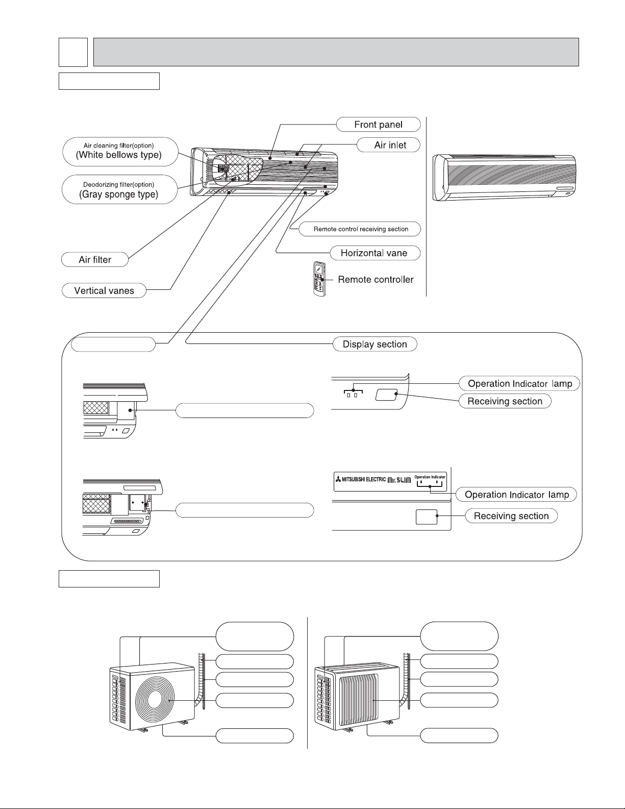
PART NAMES AND FUNCTIONS
INDOOR UNIT
MS09NW MS09NW2
Operation section
(When the front panel is opened)
MS09NW MS09NW2
MS12NN MS12NN2
MS15NN MS15NN2
MS17NN MS17NN2
MS09NW MS09NW2
MS12NN MS12NN2
MS15NN MS15NN2
MS17NN MS17NN2
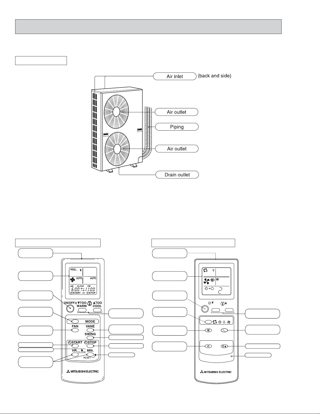
OUTDOOR UNIT
MU09NW MU09NW2
Emergency operation switch
Emergency operation switch
Air inlet
(back and side)
Piping
Drainage hose
Air outlet
MS12NN MS12NN2
MS15NN MS15NN2
MS17NN MS17NN2
MS12NN
MU12NN MU12NN2
MU15NN MU15NN2
MU17NN MU17NN2
Air inlet
(back and side)
Piping
Drainage hose
Air outlet
Drain outlet
Drain outlet
5
Page 6
MUM30NN MUM30NN2
OUTDOOR UNIT
MS09NW MS12NN MS15NN MS17NN
REMOTE CONTROLLER
Signal transmitting
section
Operation display
section
OPERATE/STOP
(ON/OFF)button
OPERATION
SELECT button
FAN SPEED
CONTROL button
ON-TIMER button
CLOCK SET button
HR. button
MIN. button
(TIME SET button)
TEMPERATURE
button
VANE CONTROL
button
SWING button
OFF-TIMER button
RESET button
MS09NW2 MS12NN2 MS15NN2 MS17NN2
REMOTE CONTROLLER
Signal transmitting
section
Operation display
section
TOO
WARM
I FEEL COOL
DRY FAN
VANE
TIME
RESET
Hr
TOO
COOL
TEMPERATURE
button
VANE CONTROL
button
TIME SET button
RESET button
OPERATE/STOP
(ON/OFF)button
OPERATION
SELECT button
FAN SPEED
CONTROL button
TIMER MODE
SELECT button
ON/OFF
MODE
FAN
SELECT
TIMER CONTROL
6
Page 7
4
When MS09NW indoor unit is operating with MUM18NW, MUM30NN and MUM30NN2 outdoor unit connected.
(Please refer to the manual No.OB202 for MUM18NW.)
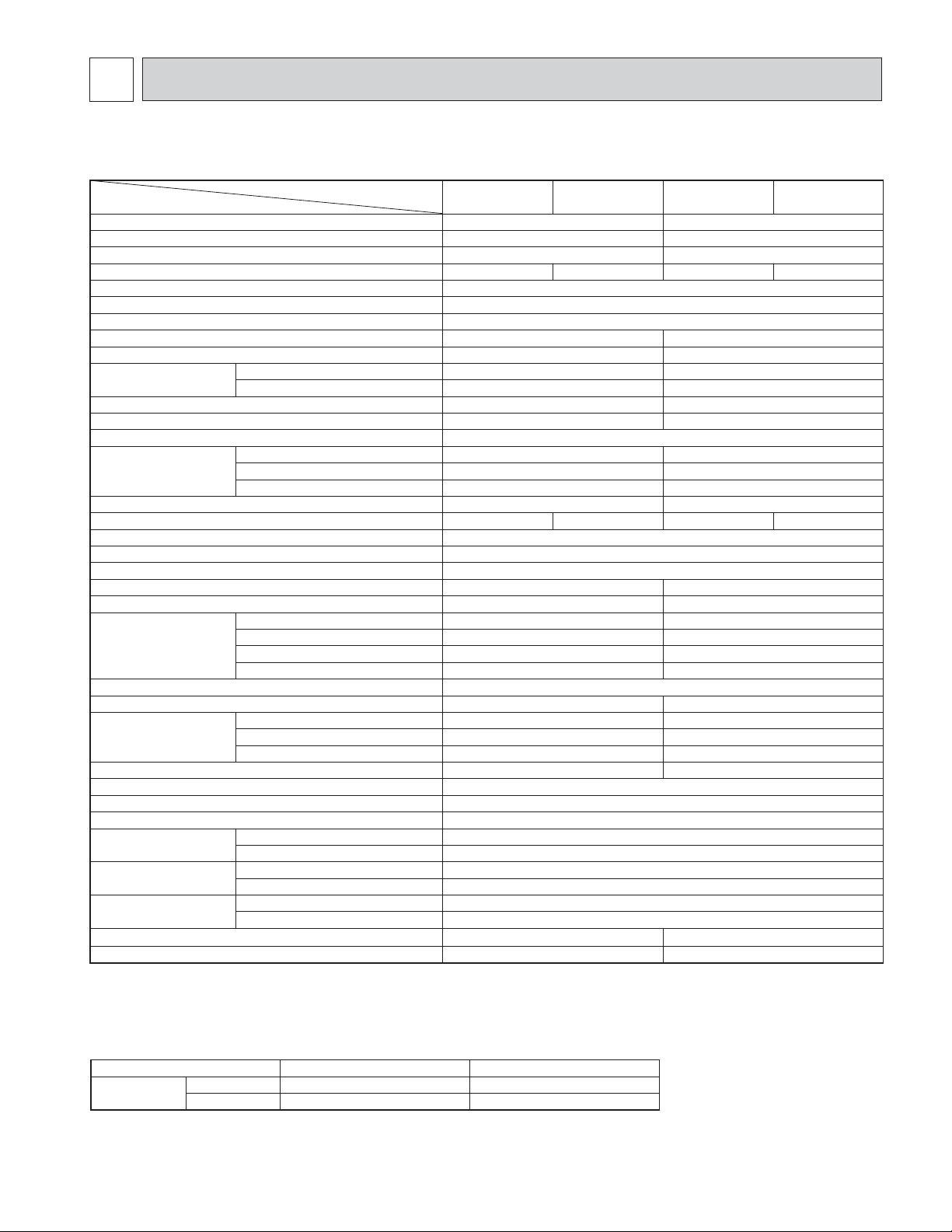
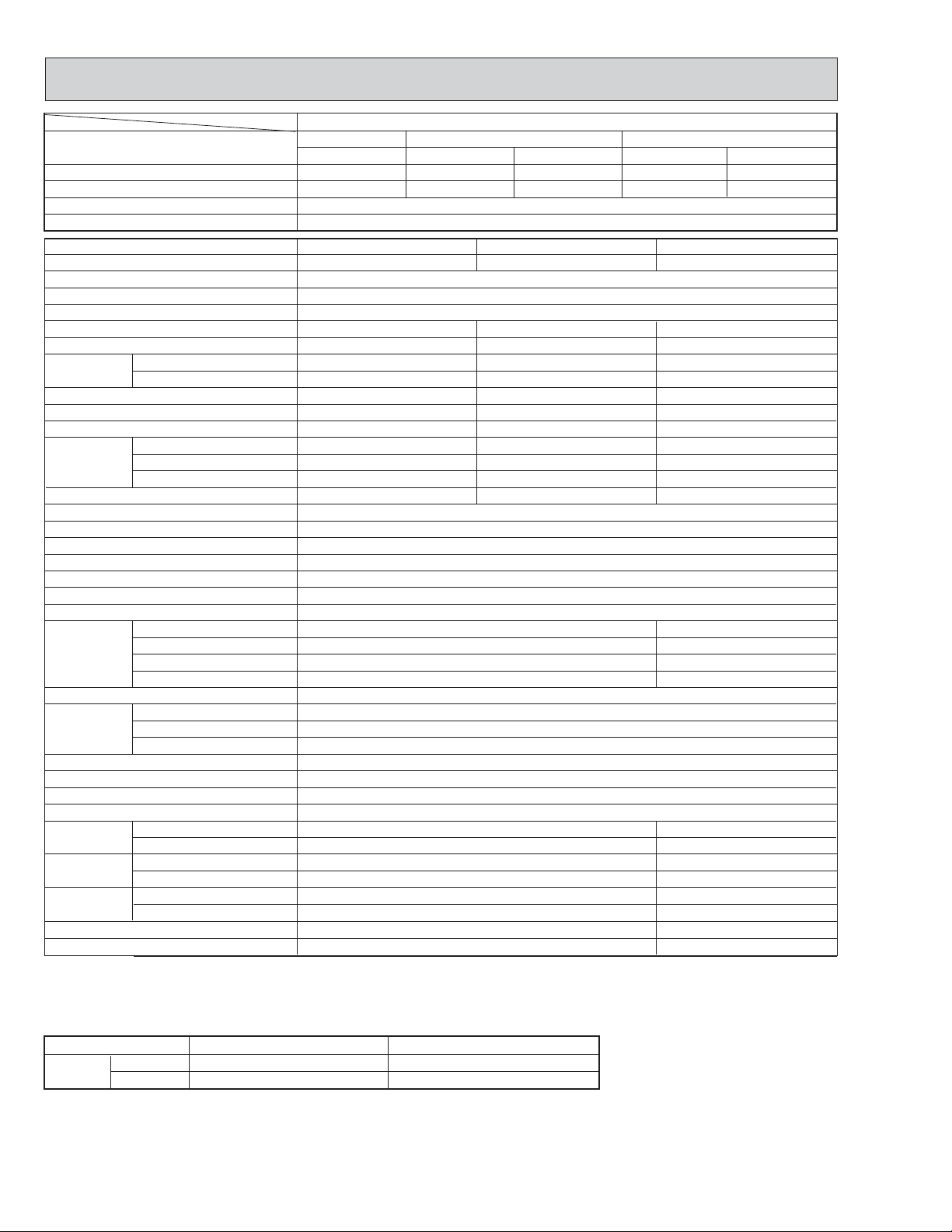
SPECIFICATIONS
ITEM MODELS
Cooling capacity
Power consumption
EER [SEER]
INDOOR UNIT MODEL
External finish
Power supply
Max. fuse size (time delay)
Min. ampacity
Fan motor
Airflow Lo—Me—Hi
Moisture removal
Sound level Lo-Me-Hi
Cond. drain connection O.D.
Dimensions
Weight
OUTDOOR UNIT MODEL
External finish
Power supply
Max. fuse size (time delay)
Min. ampacity
Fan motor
Compressor
Refrigerant control
Sound level
Dimensions
Weight
REMOTE CONTROLLER
Control voltage (by built-in transformer)
REFRIGERANT PIPING
Pipe size
Connection method
Between the indoor
& outdoor units
Refrigerant filling capacity (R-22)
Refrigerant oil (Model)
Dry
Wet
W
D
H
Model
Winding resistance (at 68˚F) "
W
D
H
Liquid
Gas
Indoor
Outdoor
Height difference
Piping length
w1
w1
w1
Btu/h
V, phase, Hz
F.L.A
CFM
CFM
Pints/h
dB(A)
V, phase, Hz
F.L.A
R.L.A
L.R.A
dB(A)
W
in.
in.
in.
in.
lbs
in.
in.
in.
lbs
in.
in.
lbs
cc
A
A
A
A
ft
ft
MS09NW
8,500
840
10.1 (10.2)
MS09NW
0.37
208-265-328
177-226-279
31-37-42
32-1/16
7-3/16
10-13/16
MU09NW
115, 1, 60
0.66
KH122WES
C-R 0.98 C-S 2.21
30-11/16
10-1/16
21-1/4
2 lbs 2 oz
270 (MS56)
MS09NW2
MS09NW2
White
115, 1, 60
15
0.5
2.3
5/8
18
MU09NW2
Munsell 5Y6.5/1
15
14
10
37
Capillary tube
46
64
Wireless type
12V DC
Not supplied (optional parts)
1/4
3/8
Flared
Flared
Max. 25
Max. 49
MS12NN
12,300/12,600
1,100/1,130
11.2/11.2 (11.3/11.3)
MS12NN
0.6
0.43
360-395-452
314-342-392
3.2
36-39-42
39-15/16
7-1/2
12-5/8
31
MU12NN
208/230, 1, 60
12
0.52
RH167NHDT
C-R 2.16 C-S 3.11
9
29
52
33-7/16
11/7/16
23-13/16
92
5/8
2 lbs 14 oz
520 (MS56)
MS12NN2
MS12NN2
MU12NN2
Notes w1 : Test conditions are based on ARI 210/240
Rating conditions (cooling) — Indoor : 80-FDB, 67-FWB, Outdoor : 95-FDB, 75-FWB
Operating Range
Indoor intake air temperature
Cooling
Maximum
Minimum
95-FDB, 71-FWB
67-FDB, 57-FWB
Outdoor intake air temperature
115-FDB
67-FDB
7
Page 8
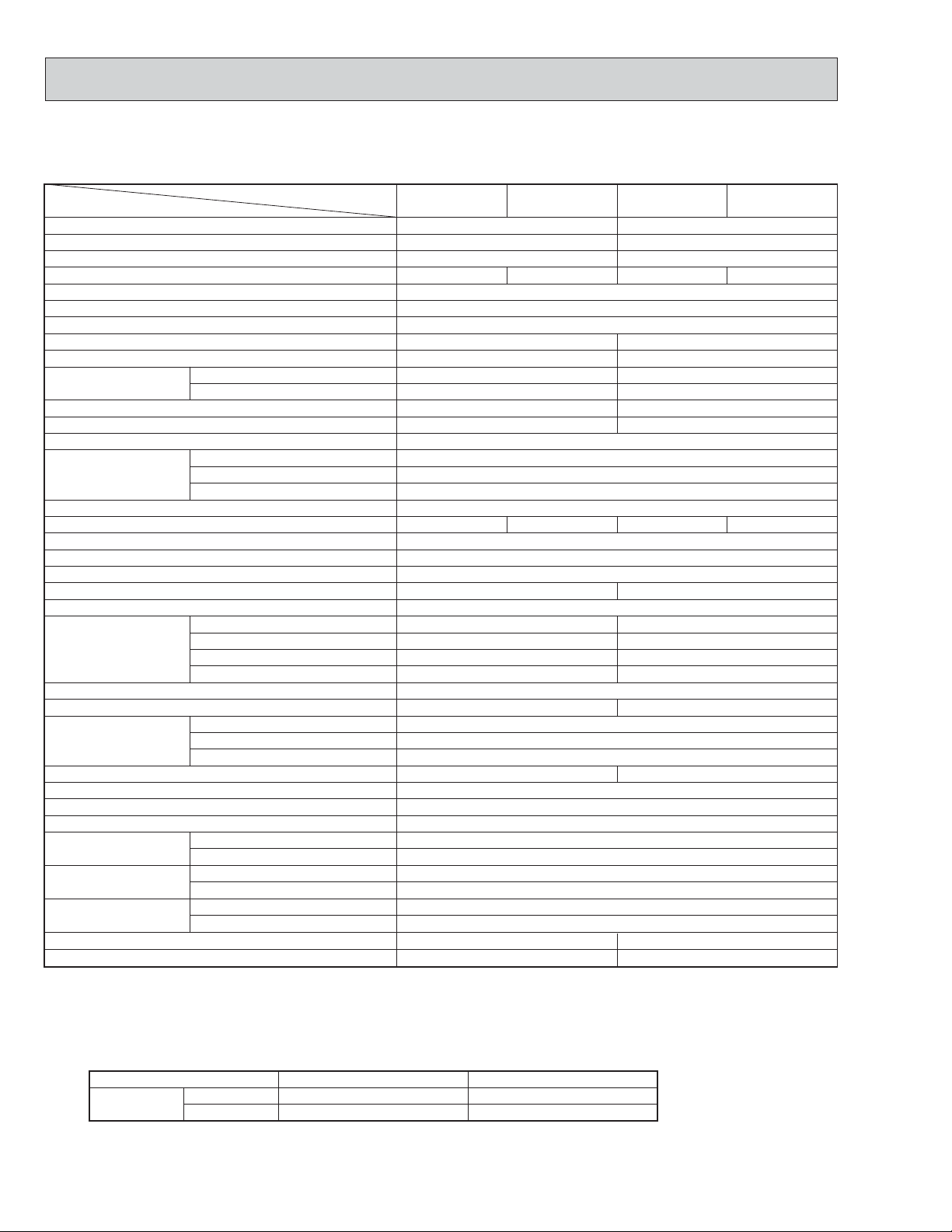
When MS15NN indoor unit is operating with MUM30NN and MUM30NN2 outdoor unit connected.
(Please refer to the manual No.OB202 for MUM18NW.)
Item Model
Cooling capacity
Power consumption
EER [SEER]
INDOOR UNIT MODEL
External finish
Power supply
Max. fuse size (time delay)
Min. ampacity
Fan motor
Airflow Lo—Me—Hi
Moisture removal
Sound level Lo-Me-Hi
Cond. drain connection O.D.
Dimensions
Weight
OUTDOOR UNIT
External finish
Power supply
Max. fuse size (time delay)
Min. ampacity
Fan motor
Compressor
Refrigerant control
Sound level
Dimensions
Weight
REMOTE CONTROLLER
Control voltage (by built-in transformer)
REFRIGERANT PIPING
Pipe size
Connection method
Between the indoor
& outdoor units
Refrigerant filling capacity (R-22)
Refrigerant oil (Model)
Dry
Wet
W
D
H
Model
Winding resistance (at 68˚F) "
W
D
H
Liquid
Gas
Indoor
Outdoor
Height difference
Piping length
w1
w1
w1
Btu/h
V, phase, Hz
F.L.A
CFM
CFM
Pints/h
dB(A)
V, phase, Hz
F.L.A
R.L.A
L.R.A
dB(A)
in.
in.
in.
in.
lbs
in.
in.
in.
lbs
in.
in.
lbs
cc
W
A
A
A
A
ft
ft
MS15NN
14,300/14,600
1,370/1,400
10.4/10.4 (10.5/10.5)
MS15NN
0.6
0.43
360-395-452
293-321-367
4.7
36-39-42
MU15NN
14
RH207NHDT
C-R 1.68 C-S 2.78
10
35
52
92
2 lbs 14 oz
520 (MS56)
MS15NN2
MS15NN2
115, 1, 60
39-15/16
12-5/8
MU15NN2
Munsell 5Y6.5/1
208/230, 1, 60
Capillary tube
33-7/16
11-7/16
23-13/16
Wireless type
12V DC
Not supplied (optional parts)
Flared
Flared
Max. 25
Max. 49
MS17NN
15,900/16,100
1,570/1,600
10.1/10.1 (10.2/10.2)
MS17NN
White
15
406-441-491
346-374-417
5/8
7-1/2
31
MU17NN
20
0.52
RH231NHDT
C-R 1.65 C-S 2.67
1/4
5/8
520 (MS56)
MS17NN2
MS17NN2
0.7
0.51
5.1
40-43-45
MU17NN2
15
11
38
52
97
3 lbs
Notes w1 : Test conditions are based on ARI 210/240
Rating conditions (cooling) — Indoor : 80-FDB, 67-FWB, Outdoor : 95-FDB, 75-FWB
Operating Range
Indoor intake air temperature
Cooling
Maximum
Minimum
95-FDB, 71-FWB
67-FDB, 57-FWB
Outdoor intake air temperature
115-FDB
67-FDB
8
Page 9
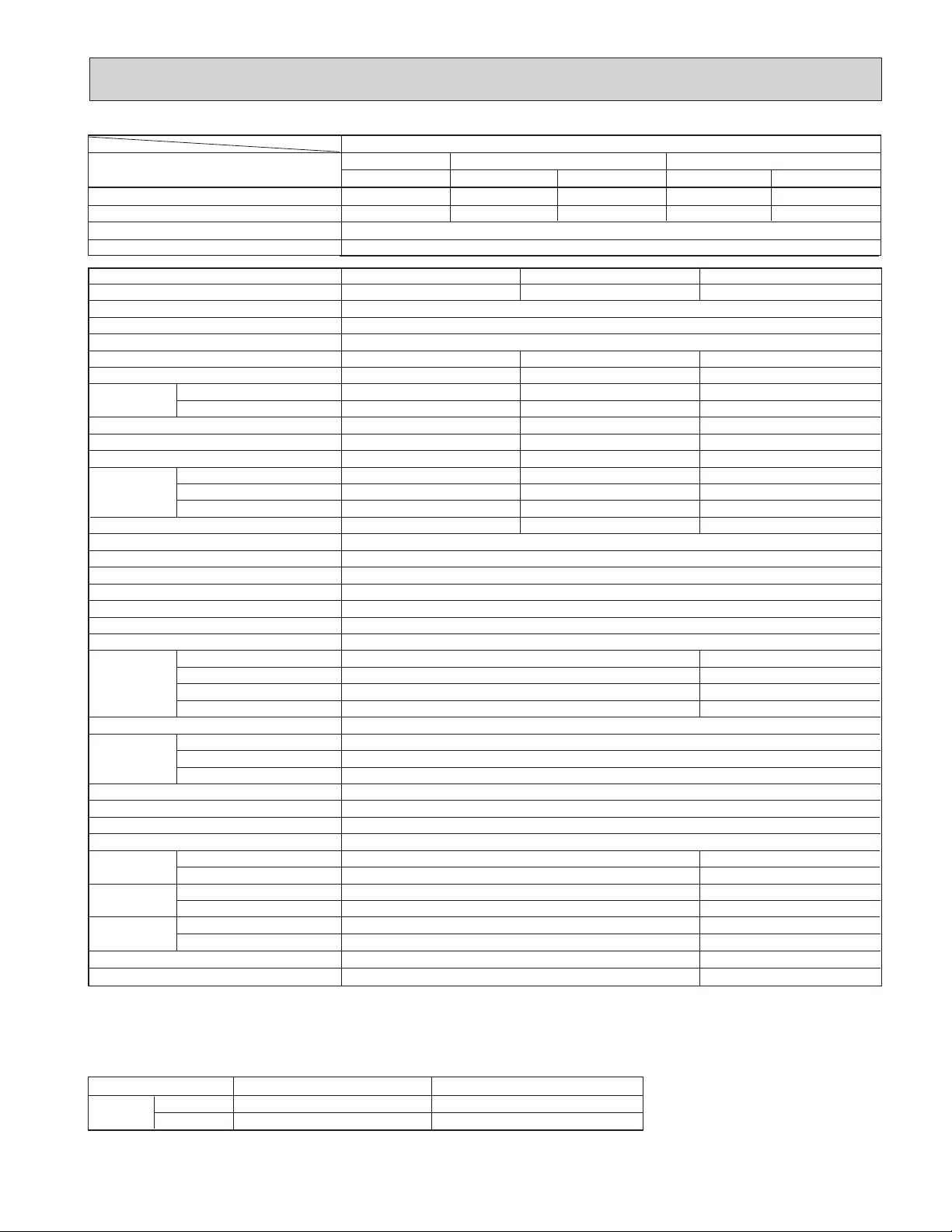
Items
Model
Cooling capacity w1 BTU/h
w1 WPower consumption
EER (Triple unit operation)
SEER (Triple unit operation)
Triple-Unit
A+B+C
28,400
2,990
DoubIe-Unit
MSM30NN
A+B
A+C or B+C
16,400 20,600
1,860
2,060
9.5
10.0
Single-Unit
A or B
C
8,200 12,400
990
1,220
INDOOR UNIT MODEL
Extenal finish
Power Supply V, Hz, Phase
Max. fuse size (time delay)
Min. ampacity
Fan motor
Airflow
Lo-Me-Hi
Dry
Wet
Moisture removal
Sound level
Cond. drain connection OD
W
Dimensions
D
H
Weight
F.L.A
CFM
CFM
(Pints/h)
dB (A)
in.
in.
in.
in.
lbs.
OUTDOOR UNIT MODEL
External fnish
Sound level
Power supply
dB (A)
V, Hz, Phase
Max. fuse sizu (time delay)
Min. ampacity
Fan motor
F.L.A
Model
Compressor
Winding resistance (at 68˚F) "
R.L.A
L.R.A
Refrigerant control
in.
in.
in.
lbs.
Dimensions
Weight
W
D
H
REMOTE CONTROLLER
Control voltage (be built-in transformer)
REFRIGERANT PIPING
Pipe size
Connection
method
Between the
indoor &
outdoor units
Liquid
Gas
Indoors
Outdoors
Height difference
Piping length
Refrigerant filling capacity (R-22)
Refrigerant oil (Model)
in.
in.
lbs.
cc
A B
MS09NW
C
MS15NNMS09NW
White
115,60,1
A
0.5
0.37
208-265-328
177-226-279
2.1
5/8
32-1/16
7-3/16
10-13/16
18
15.0
0.5
0.37
208-265-328
177-226-279
2.1
42
5/8
32-1/16
7-3/16
10-13/16
18
0.6
0.43
360-395-452
314-342-392
3.2
4242
5/8
39-15/16
7-1/2
12-5/8
31
MUM30NN
Munsell 5Y 7/1
Max. 57
208/230,60,1(3-wire)
A
30
25
0.8+0.7
KH122WEV<115V> RH167NAB<208/230V>
C-R 0.97 C-S 4.81 C-R 2.47 C-S 4.62
10 8
37 29
Capillary tube
37-7-16
15-3/8
45-5/16
240
Wireless type
DC12V
Not supplied (optional parts)
1/4 1/4
3/8 5/8
Flared Flared
Flared Flared
ft
ft
Max. 25 Max. 25
Max. 65
3 lbs 3 oz
270 (MS56)
Max. 65
3 lbs 8 oz
520 (MS56)
Notesw1. Test conditions are based on ARI 210/240
Rating conditions (cooling) — Indoor : 80˚FDB, 67˚FWB, Outdoor : 95˚FDB, 75˚FWB
Operating Range
Cooling
Maximum
Maximum
Indoor air intake temperature
90˚FDB,71˚FWB
67˚FDB,57˚FWB
Outdoor air intake temperature
115˚FDB
67˚FDB
9
Page 10
Items
Model
Triple-Unit
A+B+C
Cooling capacity w1BTU/h
w1WPower consumption
28,400
2,870
EER (Triple unit operation)
SEER (Triple unit operation)
INDOOR UNIT MODEL
Extenal finish
Power Supply V, Hz, Phase
Max. fuse size (time delay)
A
Min. ampacity
Fan motor
Airflow
Lo-Me-Hi
Dry
Wet
Moisture removal
Sound level
Cond. drain connection OD
W
Dimensions
D
H
Weight
F.L.A
CFM
CFM
(Pints/h)
dB (A)
in.
in.
in.
in.
lbs.
OUTDOOR UNIT MODEL
External fnish
Sound level
Power supply
Max. fuse sizu (time delay)
dB (A)
V, Hz, Phase
A
Min. ampacity
Fan motor
F.L.A
Model
Compressor
Winding resistance (at 68˚F) "
R.L.A
L.R.A
Refrigerant control
in.
in.
in.
lbs.
Dimensions
Weight
W
D
H
REMOTE CONTROLLER
Control voltage (be built-in transformer)
REFRIGERANT PIPING
Pipe size
Connection
method
Between the
indoor &
outdoor units
Liquid
Gas
Indoors
Outdoors
Height difference
Piping length
Refrigerant filling capacity (R-22)
Refrigerant oil (Model)
in.
in.
ft
ft
lbs.
cc
DoubIe-Unit
A+B
16,400
1,830
A B
MS09NW
0.5
0.37
208-265-328
177-226-279
2.1
5/8
32-1/16
7-3/16
10-13/16
18
KH122WES<115V> RH167NAB<208/230V>
C-R 0.98 C-S 2.21 C-R 2.47 C-S 4.62
10 8
37 29
Not supplied (optional parts)
1/4 1/4
3/8 5/8
Flared Flared
Flared Flared
Max. 25 Max. 25
Max. 65
2 lbs 14 oz
270 (MS56)
MSM30NN2
A+C or B+C
20,600
2,060
9.9
10.0
MS09NW
White
115,60,1
15.0
0.5
0.37
208-265-328
177-226-279
2.1
42
5/8
32-1/16
7-3/16
10-13/16
18
MUM30NN2
Munsell 5Y 7/1
Max. 57
208/230,60,1(3-wire)
30
25
0.8+0.7
Capillary tube
37-7/16
15-3/8
45-5/16
244
Wireless type
DC12V
A or B
8,200
990
Single-Unit
C
12,400
1,260
C
MS15NN
0.6
0.43
360-395-452
314-342-392
3.2
4242
5/8
39-15/16
7-1/2
12-5/8
31
Max. 65
3 lbs 1 oz
520 (MS56)
Notesw1. Test conditions are based on ARI 210/240
Rating conditions (cooling) — Indoor : 80˚FDB, 67˚FWB, Outdoor : 95˚FDB, 75˚FWB
Operating Range
Indoor air intake temperature
Cooling
Maximum
Maximum
90˚FDB,71˚FWB
67˚FDB,57˚FWB
Outdoor air intake temperature
115˚FDB
67˚FDB
10
Page 11
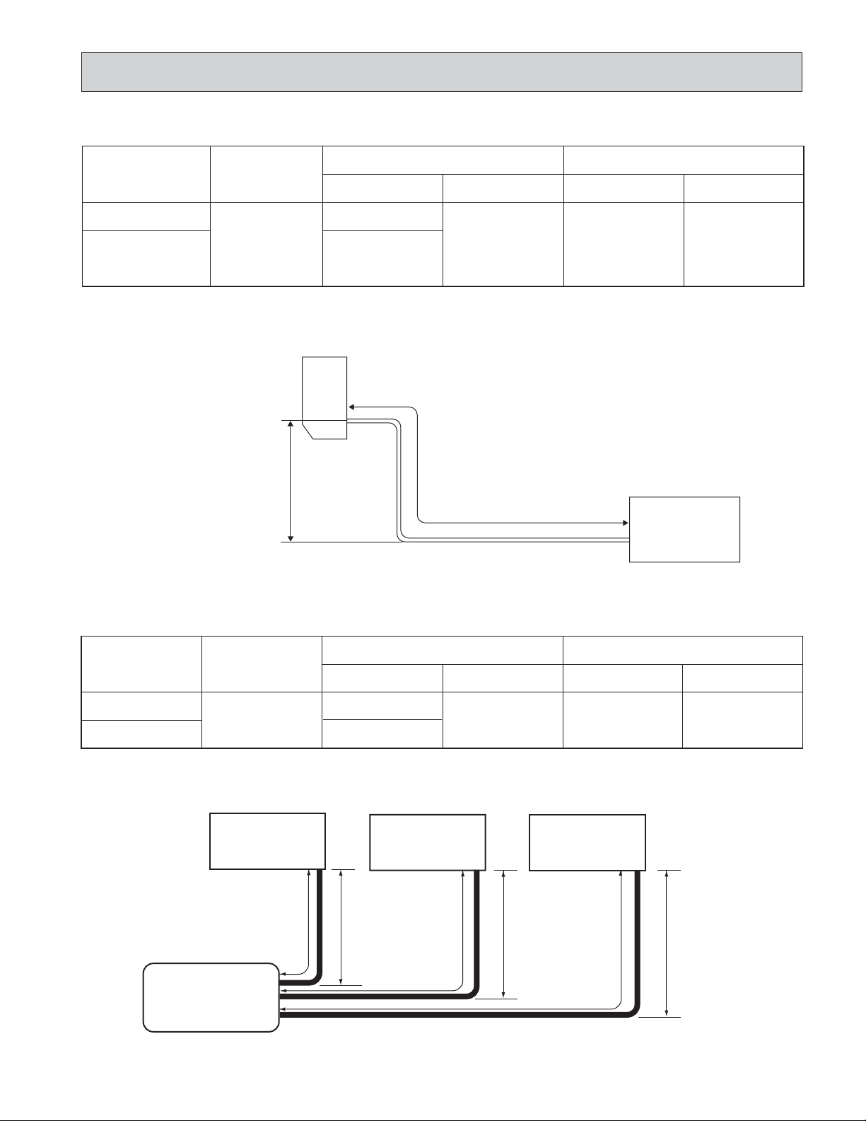
MAX. REFRIGERANT PIPING LENGTH & MAX. HEIGHT DIFFERENCE
Additional piping
Models
MS09NW MS09NW2
MS12NN MS12NN2
MS15NN MS15NN2
MS17NN MS17NN2
Max. length : ft
A
49
MAX. HEIGHT DIFFERENCE
w Height difference
should be within
25ft regardless of
which unit, indoor
or outdoor
position is high.
Indoor
unit
w Max. Height
difference 25ft
Piping size O.D. : in. Length of connecting pipe : in.
Gas
[ 3/8
[ 5/8
Liquid
[ 1/4
Additional Piping
Max. length
A
Indoor unit
16-15/16
Outdoor unit
Outdoor unit
0
MSM30NN MSM30NN2
Model
MS09NW
MS15NN
Additional piping
Max. length : ft
A
65
MAX. HEIGHT DIFFERENCE
Indoor unit A
MS09NW
Max. Length
65ft
Outdoor unit
MUM30NN
MUM30NN2
Piping size O.D. : in.
Gas Liquid Indoor unit
[3/8
[5/8
Indoor unit B
MS09NW
Max. Length
65ft
w Max. Height
difference 25ft
[1/4
Indoor unit C
MS15NN
Max. Length
65ft
w Max. Height
difference 25ft
Length of connecting pipe : in.
Outdoor unit
16-15/16
w Max. Height
difference 25ft
0
11
Page 12
5
DA T A
1. PERFORMANCE DATA
1) COOLING CAPACITY
MS09NW MS12NN MS15NN MS17NN MS09NW2 MS12NN2 MS15NN2 MS17NN2
TC
8.5
7.9
7.3
12.6
11.7
10.8
14.6
13.6
12.5
16.1
15.0
13.8
)
SHC
TPC
TC
4.8
0.93
7.8
5.5
0.89
7.3
6.1
0.86
6.6
7.3
1.25
11.6
8.3
1.20
10.8
9.1
1.15
9.8
7.5
1.55
13.4
8.8
1.48
12.5
9.8
1.43
11.4
8.3
1.77
14.8
9.7
1.70
13.8
10.8
1.63
12.6
Indoor air Outdoor intake air DB temperature (˚F
Model
MS09NW
MS09NW2
MS12NN
MS12NN2
MS15NN
MS15NN2
MS17NN
MS17NN2
Notes 1. IWB : Intake air wet-bulb temperature.
TC : Total Capacity (x10
TPC : Total Power Consumption (kW)
2. SHC is based on 80˚F of indoor intake air DB temperature.
IWB
(˚F)
71
67
63
71
67
63
71
67
63
71
67
63
3
Btu/h), SHC : Sensible Heat Capacity (x103Btu/h)
75 85 95 105 115
TC
SHC
TPC
10.4
5.9
0.75
9.9
6.9
0.71
9.3
7.7
0.67
15.4
11.6
1.01
14.6
10.4
0.95
13.7
8.9
0.90
17.9
9.2
1.25
16.9
11.0
1.18
15.9
12.5
1.12
19.7
10.2
1.42
18.7
12.1
1.34
17.5
13.7
1.28
TC
9.7
9.2
8.6
14.4
13.6
12.7
16.7
15.8
14.7
18.4
17.4
16.3
SHC
5.5
6.4
7.2
8.3
9.7
10.7
8.6
10.2
11.6
9.5
11.3
12.7
TPC
0.82
0.78
0.74
1.10
1.05
1.00
1.37
1.30
1.24
1.56
1.48
1.42
TC
9.1
8.5
8.0
13.5
12.6
11.8
15.7
14.6
13.7
17.3
16.1
15.1
SHC
5.2
6.0
6.7
7.8
8.9
10.0
8.1
9.5
10.8
8.9
10.5
11.9
TPC
0.88
0.84
0.80
1.19
1.13
1.08
1.47
1.40
1.34
1.68
1.60
1.53
MS09NWo2 MS15NNo1 MUM30NN .
PERFORMANCE DATA (ONE INDOOR UNIT WITH ONE OUTDOOR UNIT)
Indoor air Outdoor intake air DB temperature (˚F
Model
MS09NW
MS15NN
IWB
(˚F)
71
67
63
71
67
63
75 85 95 105 115
TC
SHC
TPC
TC
SHC
TPC
TC
10.05
5.89
0.88
9.39
5.51
0.97
8.82
9.51
6.85
0.83
8.86
6.38
0.92
8.20
8.94
7.63
0.79
8.28
7.07
0.88
7.71
15.19
8.76
1.09
14.20
8.19
1.19
13.33
14.38
10.21
1.03
13.39
9.51
1.13
12.40
13.52
11.40
0.98
12.52
10.56
1.08
11.66
SHC
5.17
5.90
6.58
7.69
8.80
9.83
TPC
1.04
0.99
0.95
1.28
1.22
1.17
TC
8.20
7.63
7.01
12.40
11.53
10.60
)
SHC
TPC
TC
4.81
1.09
7.54
5.49
1.05
7.01
5.98
1.01
6.40
7.15
1.35
11.41
1.29
1.24
10.60
9.67
8.19
8.94
MS09NWo2 MS15NNo1 MUM30NN2 .
PERFORMANCE DATA (ONE INDOOR UNIT WITH ONE OUTDOOR UNIT)
Indoor air Outdoor intake air DB temperature (˚F
Model
MS09NW
MS15NN
Notes 1. IWB : Intake air wet-bulb temperature
TC : Total Capacity (x10
TPC : Total Power Consumption (kW)
2. SHC is based on 80˚Fof indoor intake air DB temperature.
IWB
)
(
F
˚
71
67
63
71
67
63
10.05
15.19
14.38
13.52
3
Btu/h), SHC : Sensible Heat Capacity (x103Btu/h)
75 85 95 105 115
TC
SHC
TPC
TC
SHC
TPC
TC
5.89
0.88
9.39
5.51
0.97
8.82
9.51
6.85
0.83
8.86
6.38
0.92
8.20
8.94
7.63
0.79
8.28
7.07
0.88
7.71
8.76
1.12
14.20
8.19
1.23
13.33
10.21
1.06
13.39
9.51
1.17
12.40
11.40
1.01
12.52
10.56
1.12
11.66
2) COOLING CAPACITY CORRECTIONS
)
65ft
-
0.878
Model
MS09NW MS09NW2
MS12NN MS12NN2
MS15NN MS15NN2
MU17NN MS17NN2
MUM30NN MUM30NN2
25ft (std)
1.0
1.0
Refrigerant piping length (one way
40ft
0.954
0.954
49ft
0.927
0.927
SHC
5.17
5.90
6.58
7.69
8.80
9.83
TPC
1.04
0.99
0.95
1.32
1.26
1.20
TC
8.20
7.63
7.01
12.40
11.53
10.60
)
SHC
TPC
TC
4.81
1.09
7.54
5.49
1.05
7.01
5.98
1.01
6.40
7.15
1.39
11.41
8.19
1.34
10.60
8.94
1.29
9.67
SHC
4.4
5.1
5.5
6.7
7.6
8.3
6.9
8.1
8.9
7.7
8.9
9.8
SHC
4.43
5.05
5.46
6.58
7.53
8.16
SHC
4.43
5.05
5.46
6.58
7.53
8.16
TPC
0.97
0.93
0.89
1.30
1.25
1.20
1.61
1.55
1.48
1.84
1.78
1.70
TPC
1.14
1.10
1.05
1.40
1.35
1.29
TPC
1.14
1.10
1.05
1.45
1.40
1.37
12
Page 13
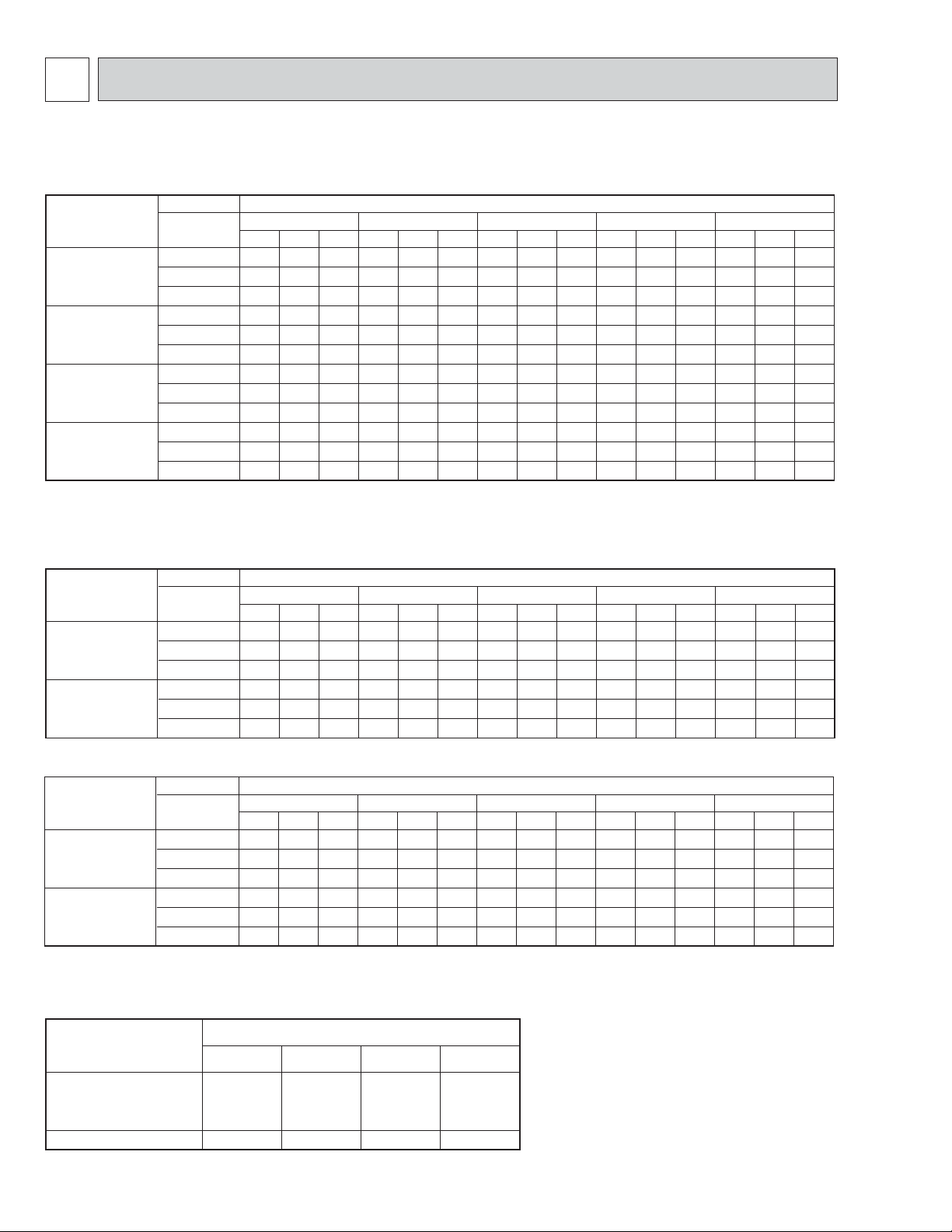
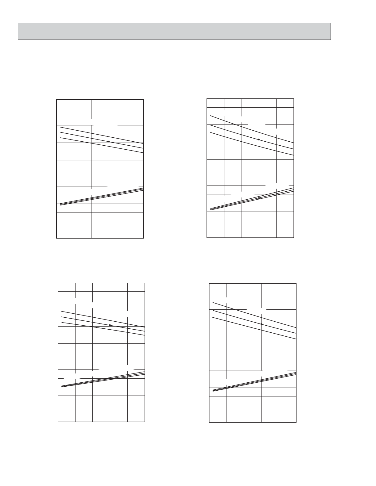
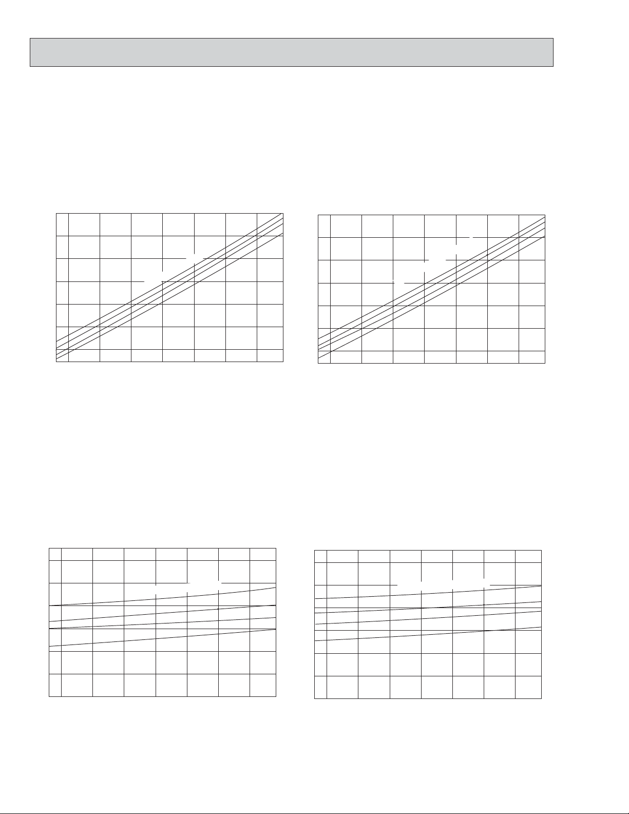
2. PERFORMANCE CURVE
NOTE : A point on the cur ve shows the reference point.
MS09NW MS09NW2 MS12NN MS12NN2
MU09NW MU09NW2 MU12NN MU12NN2
Cooling capacity
SHF at rating condition = 0.7
12
Indoor intake air WB temperature (
10
8
6
Airflow
Bypass Factor
= 279CFM
= 0.26
-F)
16
14
12
71
67
63
10
8
Cooling capacity
SHF at rating condition = 0.71
Indoor intake air WB temperature (
Airflow
Bypass Factor
= 392CFM
= 0.17
-
F)
71
67
63
1.2
Indoor intake air WB temperature (
0.8
0.6
F)
-
71
67
63
2
Indoor intake air WB temperature (
1
Total power consumption (kW) Total capacity ( o10 Btu/h)
65 75 85 95 105 115 67 75 85 95 105 115
Outdoor intake air DB temperature (-F) Outdoor intake air DB temperature (-F)
Total power consumption (kW) Total capacity ( o10 Btu/h)
MS15NN MS15NN2 MS17NN MS17NN2
MU15NN MU15NN2 MU17NN MU17NN2
Cooling capacity
SHF at rating condition = 0.7
18
16
14
12
2
Bypass Factor
Indoor intake air WB temperature (
Indoor intake air WB temperature (
Airflow
= 367CFM
= 0.22
-F)
-F)
20
18
71
67
63
71
67
63
16
14
2
SHF at rating condition = 0.65
Indoor intake air WB temperature (
Indoor intake air WB temperature (
Cooling capacity
Airflow
Bypass Factor
= 417CFM
= 0.24
-F)
-F)
71
67
63
-
F)
71
67
63
71
67
63
1
Total power consumption (kW) Total capacity ( o10 BTU/h)
67 75 85 95 105 115
Outdoor intake air DB temperature (-F)
13
1
Total power consumption (kW) Total capacity ( o10 BTU/h)
67 75 85 95 105 115
Outdoor intake air DB temperature (-F)
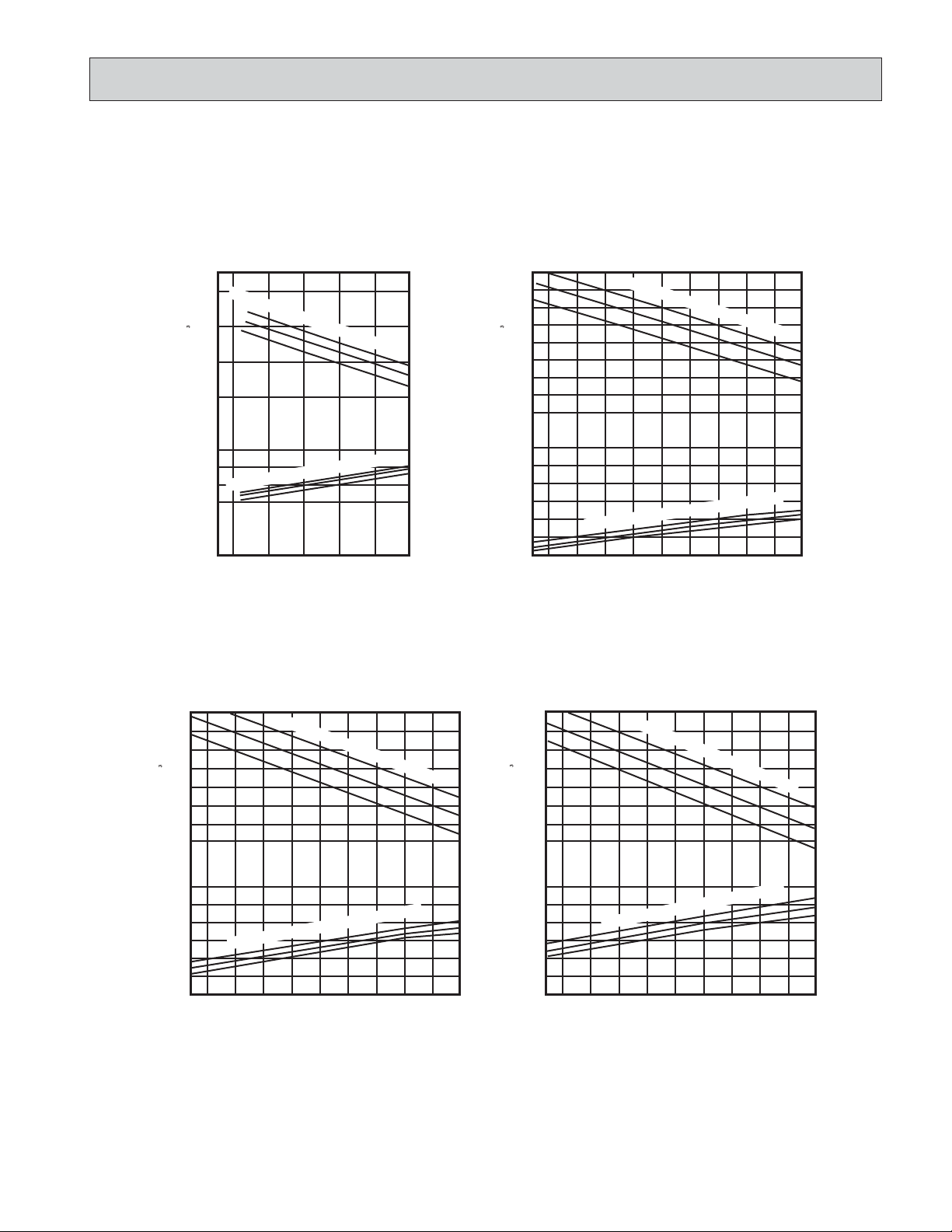
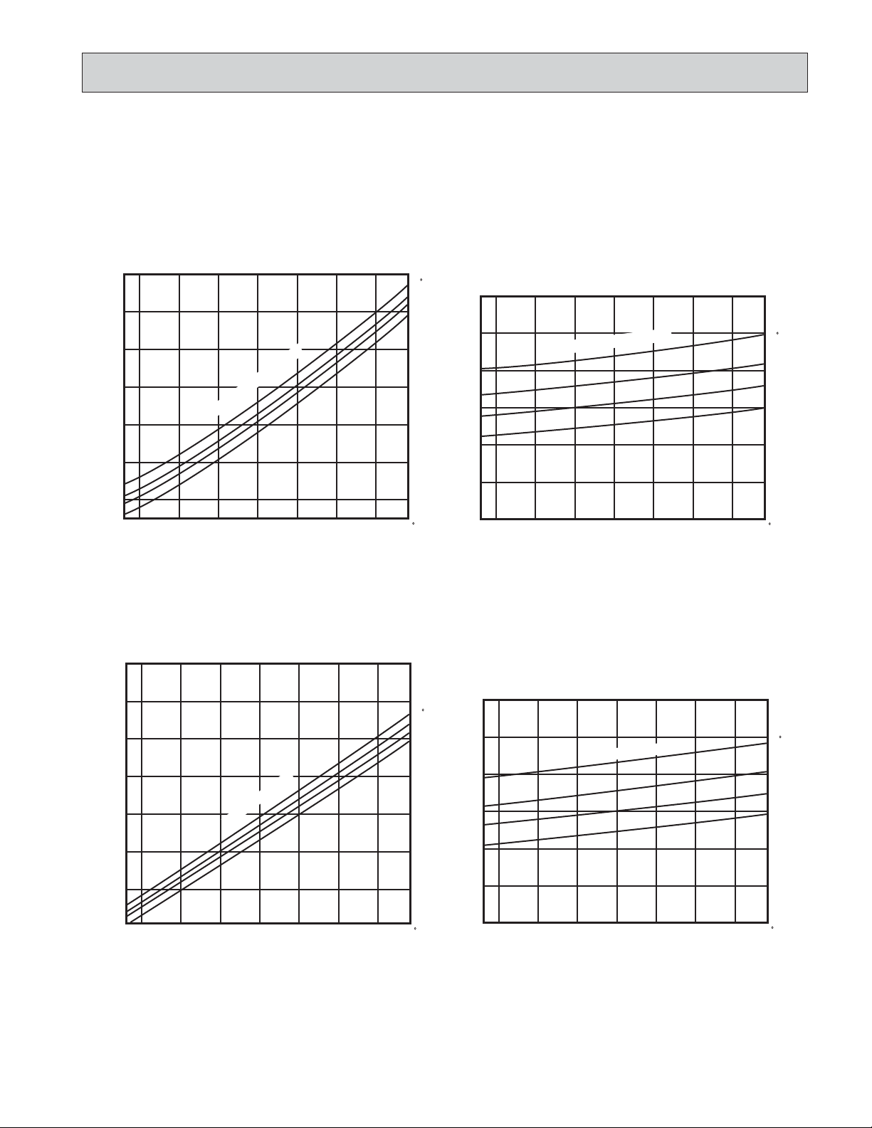
Page 14
MSM30NN MSM30NN2 (ONE INDOOR UNIT WITH ONE OUTDOOR UNIT)
NOTE : A point on the curve shows the reference point.
MS09NW
MUM30NN
Cooling capacity
SHF at rating condition = 0.72
Airflow = 279CFM
Bypass Factor = 0.24
MS15NN
MUM30NN
Airflow = 392CFM
Cooling capacity
SHF at rating condition = 0.71
Bypass Factor = 0.19
Btu/h)
3
Total power consumption (kW) Total capacity (o 10
MS09NW
MUM30NN2
12
Indoor intake air WB temperature (
10
8
6
1.2
1.0
Indoor intake air WB temperature (
0.8
0.6
75 85 95 105 115
65
Outdoor intake air DB temperature (
Cooling capacity
SHF at rating condition = 0.72
Airflow = 279CFM
Bypass Factor = 0.24
-F)
16
Btu/h)
3
14
-F)
71
67
63
71
F)
-
67
63
12
10
1.5
1.3
1.1
0.9
Total power consumption (kW) Total capacity (o 10
MS15NN
MUM30NN2
Indoor intake air WB temperature (
Indoor intake air WB temperature (
75 85 95 105 115
65
Outdoor intake air DB temperature (-F)
Cooling capacity
SHF at rating condition = 0.71
Airflow = 392CFM
Bypass Factor = 0.19
-F)
-F)
71
67
63
71
67
63
12
Btu/h)
3
Total power consumption (kW) Total capacity (o 10
Indoor intake air WB temperature (
10
8
6
1.2
Indoor intake air WB temperature (
1.0
0.8
0.6
75 85 95 105 115
65
Outdoor intake air DB temperature (-F)
-F)
-F)
71
67
63
71
67
63
14
16
Indoor intake air WB temperature (
Btu/h)
3
14
12
10
1.5
1.3
Indoor intake air WB temperature (
1.1
0.9
Total power consumption (kW) Total capacity (o 10
75 85 95 105 115
65
Outdoor intake air DB temperature (-F)
-F)
-F)
71
67
63
71
67
63
Page 15
3. CONDENSING PRESSURE AND SUCTION PRESSURE
Data is based on the condition of indoor humidity 50%.
Air flow should be set at Hi.
A point on the curve shows the reference point
MU09NW
MU09NW2
PSIG
300
280
260
240
Condensing pressure
220
200
180
170
68 70 75 80 85 90 95 100 104 F
Indoor DB temperature
Outdoor ambient temperature
86 F
80
75
70
PSIG
90
80
70
60
Suction pressure
50
40
68 70 75 80 85 90 95 100 104 F
Indoor DB temperature
86 F
80
75
70
Outdoor ambient temperature
MU12NN
MU12NN2
PSIG
300
280
260
240
Condensing pressure
220
200
180
160
68 70 75 80 85 90 95 100 104 F
Outdoor ambient temperature
Indoor DB temperature
86 F
80
75
70
PSIG
90
Indoor DB temperature
80
70
Suction pressure
60
50
40
68 70 75 80 85 90 95 100 104 F
Outdoor ambient temperature
86 F
80
75
70
15
Page 16
Data is based on the condition of indoor humidity 50%.
Air flow should be set at Hi.
A point on the curve shows the reference point
MU15NN
MU15NN2
PSIG
320
300
86 F
280
260
240
220
Condensing pressure
200
Indoor DB temperature
80
75
70
PSIG
90
80
70
60
Suction pressure
Indoor DB temperature
86 F
80
75
70
MU17NN
MU17NN2
180
160
68 70 75 80 85 90 95 100 104 F
Outdoor ambient temperature
PSIG
320
300
280
260
240
Indoor DB temperature
Condensing pressure
220
200
86 F
80
75
70
50
40
68 70 75 80 85 90 95 100 104 F
Outdoor ambient temperature
PSIG
90
Indoor DB temperature
80
70
60
Suction pressure
86 F
80
75
70
180
160
68 70 75 80 85 90 95 100 104 F
Outdoor ambient temperature
16
50
40
68 70 75 80 85 90 95 100 104 F
Outdoor ambient temperature
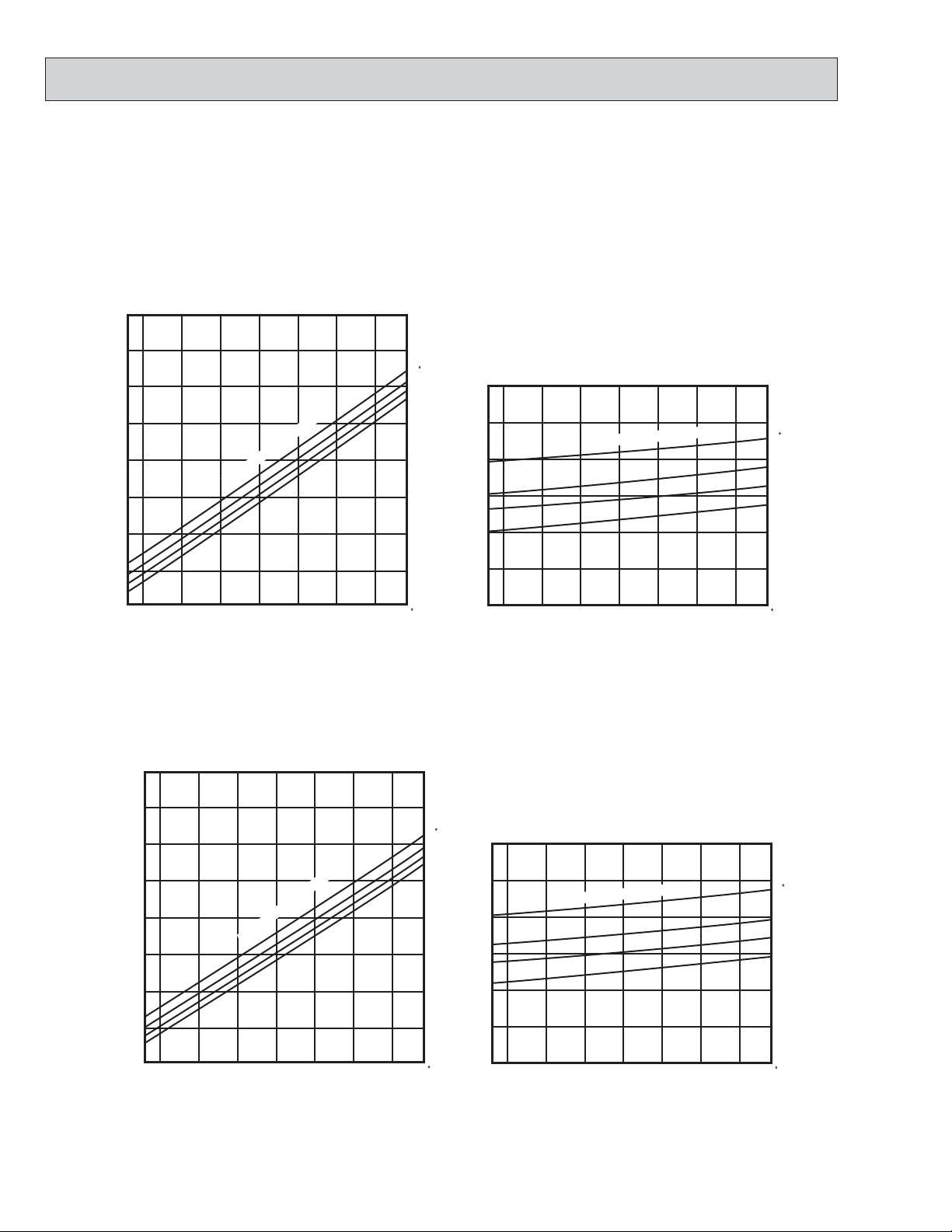
Page 17
MSM30NN
(ONE INDOOR UNIT WITH ONE OUTDOOR UNIT)
Data is based on the condition of indoor humidity 50%. Air flow should be set at HI. A point on the curve shows the reference
point.
MS09NW MS15NN
MUM30NN MUM30NN
PSIG
300
280
260
240
220
200
Condensing pressure
180
170
67
70
75 80 85 90 95 100 104-F
Outdoor ambient temperature
86-F
Indoor DB temperature
PSIG
80-F
300
75-F
70-F
280
260
240
220
200
Condensing pressure
180
170
67
70
75 80 85 90 95 100 104-F
MS09NW MS15NN
MUM30NN MUM30NN
Indoor DB temperature
Outdoor ambient temperature
86-F
80-F
75-F
70-F
PSIG
100
90
80
70
60
Suction pressure
50
40
70
67
75 80 85 90 95 100 104-F
Indoor DB temperature
Outdoor ambient temperature
PSIG
100
86-F
90
80-F
80
75-F
70
70-F
60
Suction pressure
50
40
67
17
Indoor DB temperature
86-F
80-F
75-F
70-F
70
75 80 85 90 95 100 104-F
Outdoor ambient temperature
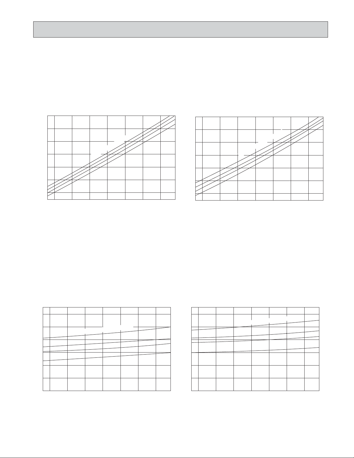
Page 18
MSM30NN2
(ONE INDOOR UNIT WITH ONE OUTDOOR UNIT)
Data is based on the condition of indoor humidity 50%. Air flow should be set at HI. A point on the curve shows the reference
point.
MS09NW MS15NN
MUM30NN2 MUM30NN2
PSIG
300
280
260
240
220
200
Condensing pressure
180
170
67
70
75 80 85 90 95 100 104-F
Outdoor ambient temperature
Indoor DB temperature
PSIG
86-F
300
80-F
75-F
70-F
280
260
240
220
200
Condensing pressure
180
170
67
70
75 80 85 90 95 100 104-F
MS09NW MS15NN
MUM30NN2 MUM30NN2
Indoor DB temperature
Outdoor ambient temperature
86-F
80-F
75-F
70-F
PSIG
100
90
80
70
60
Suction pressure
50
40
67
75 80 85 90 95 100 104-F
70
Indoor DB temperature
Outdoor ambient temperature
PSIG
100
90
86-F
80-F
80
75-F
70-F
70
60
Suction pressure
50
40
18
Indoor DB temperature
70
67
75 80 85 90 95 100 104-F
86-F
80-F
75-F
70-F
Outdoor ambient temperature
Page 19
1
4. STANDARD OPERATION DATA
MS09NW MS12NN MS15NN MS17NN MS09NW2 MS12NN2 MS15NN2 MS17NN2
Total
Electrical
circuit
Refrigerant
circuit
Indoor
unit
Outdoor
unit
Model
Item
Capacity
SHF
Input
INDOOR UNIT MODEL
Power supply (V, phase, Hz)
Input
Fan current
OUTDOOR UNIT MODEL
Power supply (V, phase, Hz)
Input
Comp. current
Fan current
Condensing pressure
Suction pressure
Discharge temperature
Condensing temperature
Suction temperature
Comp. shell bottom temp
Ref. pipe length
Refrigerant charge
Intake air temperature
Discharge air temperature
Fan speed
Airflow (Hi)
Intake air temperature
Fan speed High / Low
Airflow
DB
WB
DB
WB
DB
WB
MS09NW MS09NW2
Unit
Btu / h
—
kW
MS09NW MS09NW2
kW
A
MU09NW MU09NW2
kW
A
A
PSIG
PSIG
˚F
˚F
˚F
˚F
ft
—
˚F
˚F
˚F
˚F
rpm
CFM
˚F
˚F
rpm
CFM
Cooling
8,500
0.7
0.84
115, 1, 60
0.035
0.34
115, 1, 60
0.805
6.49
0.66
259
80
161
117
49
137
25
2 lbs 2oz
80
67
60
57
1,230
279
95
—
780
1,024
MS12NN MS12NN2
Cooling
12,300/12,600
0.71
1.10/1.13
MS12NN MS12NN2
115, 1, 60
0.047
0.41
MU12NN MU12NN2
208/230, 1, 60
1.053/1.083
4.71/4.31
0.49
243
78
157
112
48
140
25
2 lbs 14 oz
80
67
58
56
1,200
392
95
—
830/900
1,324/1,430
MS15NN MS15NN2
Cooling
14,300/14,600
0.65
1.37/1.40
MS15NN MS15NN2
115, 1, 60
0.047
0.41
MU15NN MU15NN2
208/230, 1, 60
1.323/1.353
6.01/5.51
0.49
256
77
166
116
48
154
25
2 lbs 14 oz
80
67
55
54
1,200
367
95
—
830/900
1,324/1,430
MS17NN MS17NN2
15,900/16,100
MS17NN MS17NN2
MU17NN MU17NN2
208/230, 1, 60
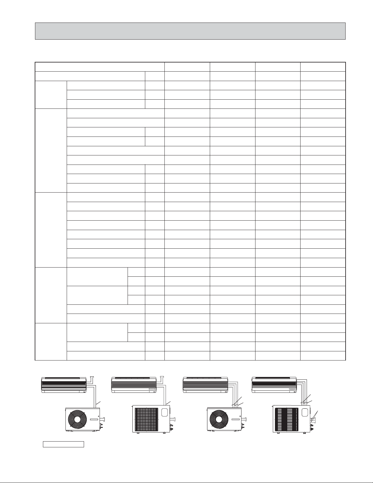
POWER SUPPLY
MS09NW
INDOOR UNIT
115V 60Hz, 1[
MS12/15/17NN
INDOOR UNIT
115V 60Hz, 1[
MS09NW2
INDOOR UNIT
MS12/15/17NN2
INDOOR UNIT
Cooling
0.65
1.57/1.60
115, 1, 60
0.054
0.47
1.516/1.546
7.01/6.41
0.49
252
77
174
114
46
160
25
3lbs oz
80
67
56
54
1,290
417
95
—
830/900
1,288/1,394
SIGNAL WIRE
OUTDOOR UNIT
• The following wiring can also apply to MS09NW2, MS12/15/17NN2.
2 wire 12V DC
Field installed
115V
60Hz, 1[
OUTDOOR UNIT
SIGNAL WIRE
2 wire 12V DC
Field installed
208/230V
60Hz, 1[
✻ Control voltage
Power supply voltage to serial signal circuit is 12V DC.Between
19
SIGNAL WIRE
2 wire 12V DC
OUTDOOR UNIT
+ and 2-- on in-out terminal block will be 12V DC peak voltage.
115V 60Hz, 1[
Field installed
115V
60Hz, 1[
OUTDOOR UNIT
SIGNAL WIRE
2 wire 12V DC
115V 60Hz, 1[
115V
Field installed
208/230V
60Hz, 1[ 3wire
Page 20
1
STANDARD OPERATION DATA
MSM30NN
MODEL Triple
Item
DB
WB
DB
WB
DB
WB
BTU/h
—
0.72 0.72 0.71 0.72
kW
MS09NW MS09NW MS15NN MS09NW MS09NW MS09NW MS15NN MS09NW MS15NN
0.035
kW
0.34
A
kW
7.0
A
A
-F
-F
-F
-F
ft
—
-F
-F
-F
-F
273
80
154
122
47
130
25
3 lbs 3 oz
80
67
60
57
1,230
279
PSIG
PSIG
R.P.M.
CFM
-F
-F
R.P.M.
CFM
Electrical
circuit
Refrigerant
circuit
Indoor
side
Outdoor
side
Capacity
SHFTotal
Input
Indoor unit model
Power supply (V,Hz,{)
Input
Fan current
Outdoor unit model
Power supply (V,Hz,{)
Input
Comp. current
Fan current
Condensing pressure
Suction pressure
Discharge temp.
Condensing temp.
Suction temp.
Comp.shell botton temp.
Ref.pipe length
Refrigerant charge
Entering
air temp.
Discharge
air temp.
Fan speed
Airflow (Hi)
Entering
air temp.
Fan speed
Airflow
MSM30NN
A+B+C
Double
A+BA
+
C or B+C
A or B
Single
C
CoolingUnit
28,400 16,400 20,600 8,200 12,400
0.71
0.72 0.71
2.99 1.86 2.06 0.99 1.22
115,60,1 115,60,1 115,60,1
0.035
0.34
0.047
0.41
0.035
0.34
0.035
0.34
0.035
0.34
0.047
0.41
0.035
0.34
0.047
0.41
MUM30NN
208/230,60,1(3-wire)
2.873 1.79 1.978 0.955 1.173
7.0 3.8 7.0 7.0 7.0 3.8 7.0 3.8
0.7+0.8 0.65+0.75 0.6+0.7
264
80
157
118
47
130
25
3 lbs 3 oz
80
67
60
57
1,230
279
243
82
169
111
54
145
25
3 lbs 8 oz
80
67
58
57
1,200
392
262
78
197
118
60
171
25
3 lbs 3 oz
80
67
60
57
1,230
279
263
79
171
116
47
146
25
3 lbs 3 oz
80
67
60
57
1,230
279
269
78
151
118
47
124
25
3 lbs 3 oz
80
67
60
57
1,230
279
240
82
169
110
54
144
25
3 lbs 8 oz
80
67
58
57
1,200
392
267
80
143
121
52
129
25
3 lbs 3 oz
80
67
60
57
1,230
279
267
85
141
118
51
139
25
3 lbs 8 oz
80
67
58
57
1,200
392
95 95 95
———
850/940 750/840 0/1030
2,720 2,360 1,039
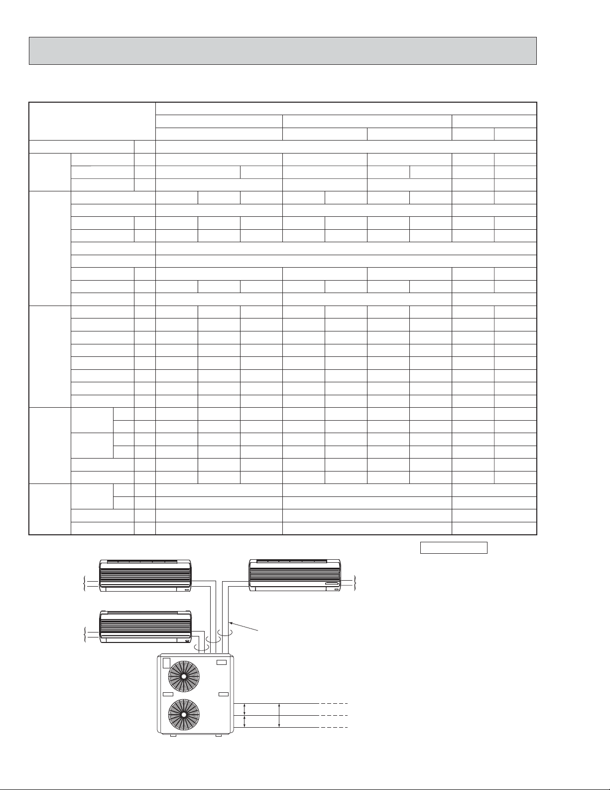
POWER SUPPLY
115V,60Hz,1{
115V,60Hz,1{
INDOOR UNIT B
INDOOR UNIT A
OUTDOOR UNIT
INDOOR UNIT C
SIGNAL WIRE 2wire 12V DC
115V common
115V 230V
20
115V,60Hz,1{
POWER SUPPLY
208/230V,60Hz,
1{ 3wire
✻ Control voltage
Power supply voltage to serial
signal circuit is 12V DC.
Between
+ and 2-- on in-out
terminal block will be 12V DC
peak voltage.
Page 21
1
STANDARD OPERATION DATA
MSM30NN2
MODEL Triple
Item
Capacity
SHFTotal
Input
Indoor unit model
Power supply (V,Hz,{)
Input
Electrical
circuit
Fan current
Outdoor unit model
Power supply (V,Hz,{)
Input
Comp. current
Fan current
Condensing pressure
Suction pressure
Discharge temp.
Refrigerant
circuit
Condensing temp.
Suction temp.
Comp.shell botton temp.
Ref.pipe length
Refrigerant charge
Entering
air temp.
Indoor
side
Discharge
air temp.
Fan speed
Airflow (Hi)
Entering
Outdoor
side
air temp.
Fan speed
Airflow
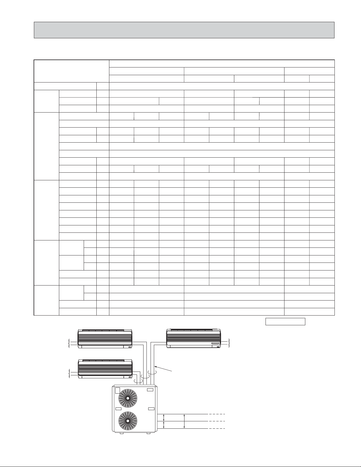
POWER SUPPLY
115V,60Hz,1{
BTU/h
—
kW
kW
A
kW
A
A
PSIG
PSIG
-F
-F
-F
-F
ft
—
DB
-F
WB
-F
DB
-F
WB
-F
R.P.M.
CFM
-F
DB
-F
WB
R.P.M.
CFM
INDOOR UNIT B
INDOOR UNIT A
0.72 0.72 0.71 0.72
MS09NW MS09NW MS15NN MS09NW MS09NW MS09NW MS15NN MS09NW MS15NN
0.035
0.34
7.0
246
78
146
112
50
130
25
2 lbs 14oz
80
67
60
57
1,230
279
MSM30NN2
A+B+C
Double
A+BA
+
C or B+C
A or B
Single
C
CoolingUnit
28,400 16,400 20,600 8,200 12,400
0.71
0.72 0.71
2.87 1.83 2.06 0.99 1.26
115,60,1 115,60,1 115,60,1
0.035
0.34
0.047
0.41
0.035
0.34
0.035
0.34
0.035
0.34
0.047
0.41
0.035
0.34
0.047
0.41
MUM30NN2
208/230,60,1(3-wire)
2.753 1.760 1.978 0.955 1.213
7.03.87.07.07.03.87.03.8
0.6+0.7 0.45+0.55 0.45+0.55
247
78
149
115
48
130
25
2 lbs 14oz
80
67
60
57
1,230
279
252
81
167
112
51
140
25
3 lbs 1 oz
80
67
58
57
1,200
392
266
78
157
120
47
138
25
2 lbs 14oz
80
67
60
57
1,230
279
263
77
157
119
47
139
25
2 lbs 14oz
80
67
60
57
1,230
279
264
77
156
119
47
138
25
2 lbs 14oz
80
67
60
57
1,230
279
262
85
169
117
57
152
25
3 lbs 1 oz
80
67
58
57
1,200
392
263
77
156
119
47
146
25
2 lbs 14oz
80
67
60
57
1,230
279
259
84
167
116
53
148
25
3 lbs 1 oz
80
67
58
57
1,200
392
95 95 95
———
880/960 650/720 650/720
2,789 2,047 2,047
INDOOR UNIT C
✻ Control voltage
Power supply voltage to serial
signal circuit is 12V DC.
115V,60Hz,1{
Between
+ and 2-- on in-out
terminal block will be 12V DC
peak voltage.
115V,60Hz,1{
OUTDOOR UNIT
SIGNAL WIRE 2wire 12V DC
115V common
115V 230V
21
POWER SUPPLY
208/230V,60Hz,
1{ 3wire
Page 22
5. OPERATING RANGE
(1) POWER SUPPLY
Rating
115V 60Hz 1[
208/230V 60Hz 1[
Indoor unit
Outdoor unit
Models
MS09NW MS09NN2
MS12NN MS12NN2
MS15NN MS15NN2
MS17NN MS17NN2
MU09NW MU09NW2
MU12NN MU12NN2
MU15NN MU15NN2
MU17NN MU17NN2
MUM30NN
MUM30NN2
(2) OPERATION
Function
Cooling
Intake air
temperature
Condition
Standard temperature
Maximum temperature
Minimum temperature
Maximum humidity
DB (-F)
80
95
67
Indoor
WB (-F)
78%
6. OUTLET AIR SPEED AND COVERAGE RANGE
Model
MS09NW MS09NW2
MS12NN MS12NN2
MS15NN MS15NN2
MS17NN MS17NN2
Function
Dry
Wet
Dry
Wet
Dry
Wet
Dry
Wet
Air flow
(CFM)
328
279
452
392
452
367
491
417
Air speed
(ft/sec.)
0.1
0.1
0.1
0.1
0.1
0.1
0.1
0.1
Coverage
range (ft)
25.6
21.8
29.2
25.5
29.2
23.9
31.7
27.0
● The air coverage range is the value up to the position
where the air speed is 1 ft/sec, when air is blown out
horizontally from the unit properly at the High speed
position.
The coverage range should be used only as a general guideline since it varies according to the size of
the room and furniture arranged in the room.
7. ADDITIONAL REFRIGERANT CHARGE (R-22(oz))
67
71
57
Guaranteed Voltage
Min. 103V — Max. 127V
Min. 198V 208V 230V Max. 253V
Outdoor
DB (-F)
95
115
67
—
WB (-F)
—
—
—
Model
MS09NW MU09NW
MS09NW2 MU09NW2
MS12NN MU12NN
MS12NN2 MU12NN2
MS15NN MU15NN
MS15NN2 MU15NN2
MS17NN MU17NN
MS17NN2 MU17NN2
MUM
30NN
MUM
30NN2
MS09NW
MS15NN
MS09NW
MS15NN
Outdoor unit
precharged
(up to 25ft)
2 lbs 2 oz
2 lbs 14 oz
2 lbs 14 oz
3lbs
3lbs 3 ozo2
3 lbs 8 oz
2lbs 14 oz o2
3 lbs 1 oz
25ft
0
0
30ft
1
1
22
Refrigerant piping length (one way)
33ft
1
1
40ft
2
2
45ft
2
2
49ft
3
3
65ft
-
5
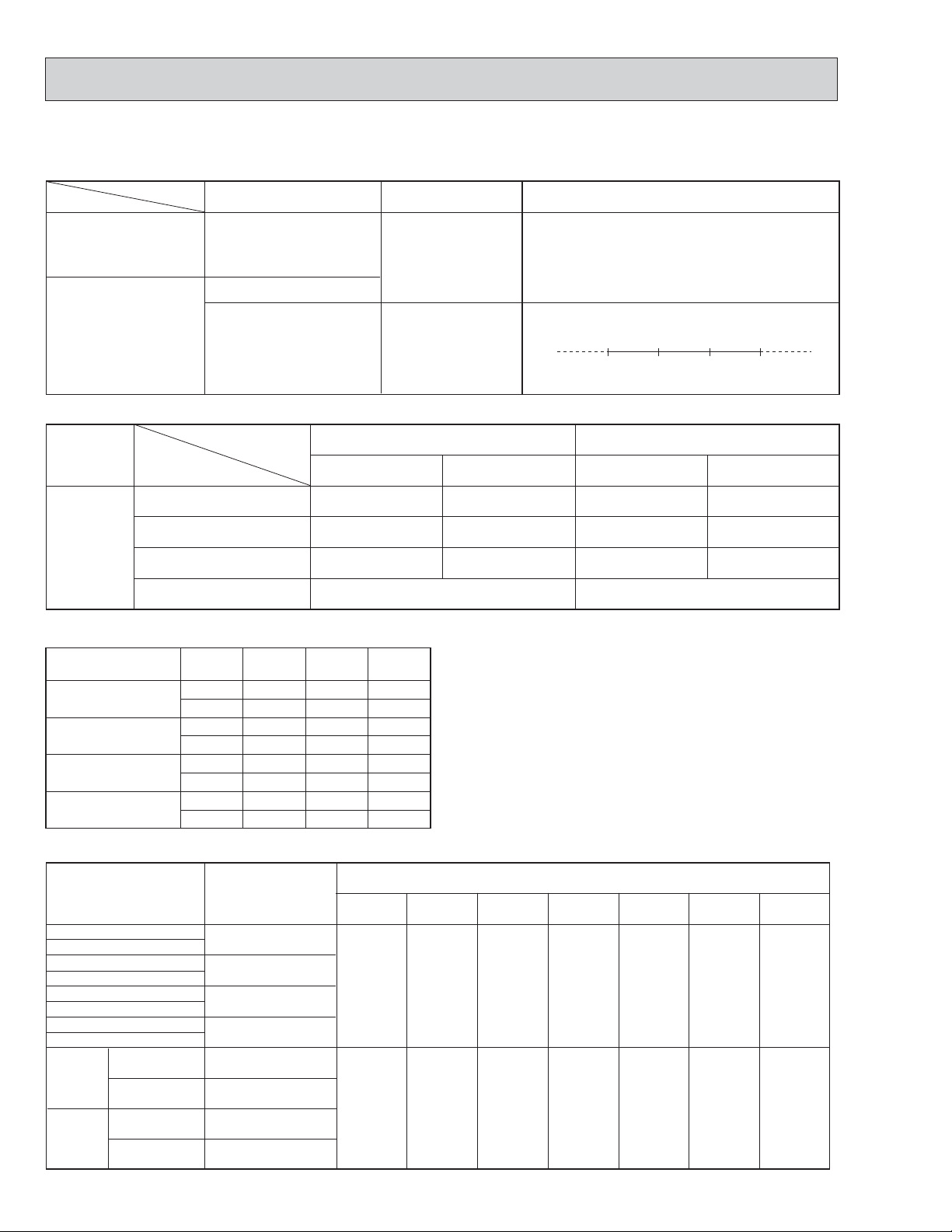
Page 23
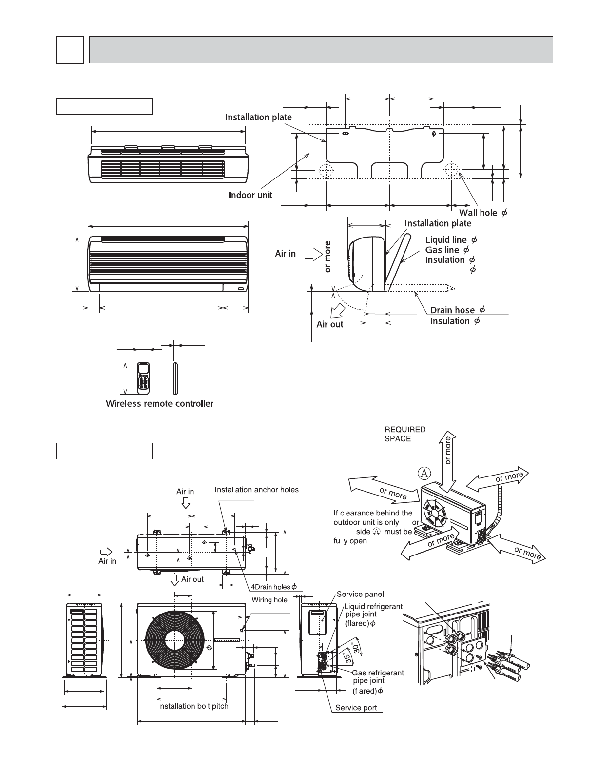
6
OUTLINES AND DIMENSIONS
MS09NW MS09NW2
INDOOR UNIT
30-13/16
32-1/16
10-13/16
2-3/8
2-3/16
24-5/8
11/16
5-1/8
3-5/16
3-5/16
7-3/8
1-5/8
1/4
3-15/16
8-7/8
12-11/16
7-3/16
8-7/8
12-3/8
3/16
2-13/16
3-9/16
{
5-1/4
3-11/16
1/4-19-11/16
3/8-16-15/16
1-3/8 O.D.
3/4 I.D
Unit : inch
8-11/16
7-3/16
1/8
1-13/16
2-9/16
5/8
1-1/8
10-3/8 3/8
6-5/16
MU09NW MU09NW2
OUTDOOR UNIT
12-5/8
7/8
10-1/16
21-1/4
10-5/16
11-1/4
12-5/8
3/8
9-13/16
11/16
1-11/16
4-13/16
30-11/16
19-5/8
12-5/16
3-9/16
16-11/16
4-3/8 o 13/16
1-1/4
3/4
2-13/16
1-15/16
1-1/16
12-5/8
11-1/4
9/16 9/16
(5/16 o 7/8)
2-3/8
13-1/2
2-9/16
3-9/16
2-9/16
5/8
7/16
4
4-3/16
20 in
4 in.
4 in.
4 in.
16
14 in.
16 in.
Lock nut
1/4
3/8
NOTE: Do not wire 12V DC and 115V AC
in same conduit hole.
This figure shows about MU09NW2.
Conduit
cover
Connector
23
Page 24
MS12NN MS15NN MS17NN MS12NN2 MS15NN2 MS17NN2
Wireless remote controller
.
INDOOR UNIT
5-7/8
7/16 ✕ 13/16
25-1/2
Unit : inch
8-9/16
12-5/8
1-15/16
39-3/16
39-15/16
30-1/2
2-3/16
6-5/16
11/16
7-1/2
2-3/8
1-9/16
17-11/16
17-11/16
17-1/4
7-1/2
MU12NN MU15NN MU17NN MU12NN2 MU15NN2 MU17NN2
OUTDOOR UNIT
13-7/8
3/16
Installation plate
{
13/161/8
10-13/161011-11/16
2-15/16
5/16-19-11/16
1/2-16-15/16
1-15/16 O.D.
1-1/8 I.D.
5/8
1-1/8
1-3/8
9-3/4
23-13/16
11-1/2
13/16
13-12/16
5/8
7-3/16
19-11/16
33-7/16
13/16
1-15/16
11-7/16
1-3/16
6-3/16
2-15/16
12-3/16
3-15/16
13-9/16
6-5/16
24
4 in.
4 in.
4 in.
14 in.
20 in.
Lock nut
1/4
Conduit
5/8
NOTE: Do not wire 12V DC and
This figure shows about MU12/15/17NN2.
cover
115V AC in same conduit hole
Connector
Page 25

MODEL : MUM30NN MUM30NN2
OUTDOOR UNIT
Unit : inch
NOTE: Do not wire 12V DC and 115V AC
in same conduit hole.
4 wiring holes
{7/8
Refrigerant pipe
(Flared) {5/8
Refrigerant pipe
(Flared) {3/8
2-3/8
2-3/8
2-3/8
2-3/8
NOTE : The symbol { indicates the diameter.
Refrigerant pipe (Flared) {1/4
2-3/8
2-15/16
Air intake
Min.4in.
Air intake
Drainage hole
Min.12in.
Space for servicing
wining and piping
2-9/16
5-15/16
18-3/4
Air intake
Air outlet
{1
13-5/8
3-3/16
Drainage
hole
2-{1
Air outlet
12-1/4
20-1/2
12-5/8
25-5/8
handle for
moving
{1
37-7/16
Min.36in.
4-{7/16
Installation anchor hole
1-13/16
2
5-15/16
Earth terminal
Service panel
1
Min.4in.
Min.33in.
7/16
16-9/16
7/16
45-5/16
15-3/8
1
17-3/8
Electrical
box
2-1/16
2-5/32
25
Page 26

7
WIRING DIAGRAM
MS09NW
MODEL WIRING DIAGRAM
INDOOR UNIT
TB
2 -
TO OUTDOOR
UNIT
CONNECTING
WIRES
12V DC
POWER
SUPPLY
115V
1 phase
60Hz
GROUND
POWER MONITOR,
RECEIVER
P.C.BOARD
SYMBOL
C11
F11
HIC1
MF
NOTE:1.For the outdoor electric wiring, refer to the outdoor unit electric wiring diagram .
INDOOR FAN CAPACITOR
FUSE (3A)
DC / DC CONVERTER
INDOOR FAN MOTOR (INNER FUSE)
2. Use copper conductors only.(For field wiring)
3. Symbols below indicate.
:Terminal block, :Connector
NAME
YLW
w
1 +
VLT
w
N
BLK
w
L1
RED
REMOTE
CONTROLLER
LD101
CN
104
5
AUTO RESTART
ASSEMBLY
(AUTO RESTART ASSEMBLY is included in indoor electronic control P.C. board
from product number 7004651T)
5
SYMBOL
MV
NR11
RT11
RT12
CN202
1
2
CN201
1
2
3
TAB12
CN
151
MV
ELECTRONIC CONTROL P.C BOARD
5
NAME NAME
VANE MOTOR
VARISTOR
ROOM TEMPERATURE THERMISTOR
COIL TEMPERATURE THERMISTOR
HIC1
TRANS
F11
SR11
NR11
SYMBOL
SR11
TB
CN
112
CN
111
3
CN
121
C11
3
2
1
CN211
SOLID STATE RELAY
TERMINAL BLOCK
BLK
GRY
YLW
BRN
WHT
RED
RT12
RT11
1
2
3
MF
4
5
6
MU09NW
MODEL WIRING DIAGRAM
OUTDOOR UNIT
GROUND
POWER SUPPLY
115V
1 phase 60Hz
FROM INDOOR UNIT
CONNECTING WIRES
12V DC
SYMBOL
C1
C2
MC
NOTE:1.Use copper conductors only.(For field wiring)
COMPRESSOR CAPACITOR
OUTDOOR FAN CAPACITOR
COMPRESSOR
2. “w”show the terminals with a lock mechanism, so they can not be removed when you pull
the lead wire.
Be sure to pull the wire by pushing the locking lever(projected part) of the terminal with a finger.
3. Symbols below indicate.
:Terminal block, :Connector
NAME NAME NAME
TB
L1
ww w
RED
N
w
BLK
w
VLT 1
2 -
w
YLW 2
SYMBOL
52C 51C
NO
COM
w
52C
w
MF
TB1
51C
OUTDOOR FAN MOTOR (INNER PROTECTOR)
TERMINAL BLOCK
OVER CURRENT RELAY
WHT WHT
WHT
2
C2
1
WHT
C1
WHT
BLK
RED
RED
BLK1 +
1
2
3
WHT
BLK
RED
C
MC
S
R
MF
SYMBOL
52C
CONTACTOR
1.Slide the sleeve.
2.Pull the wire while
pushing the locking
lever.
26
Page 27

MS12NN MS15NN MS17NN
INDOOR UNIT
TB
2 -
YLW
1 +
N
L1
w
w
w
VLT
BLK
RED
BRN
DSAR
GRN/YLW
TO OUTDOOR
UNIT
CONNECTING
WIRES
12V DC
POWER
SUPPLY
115V
1 phase
60Hz
GROUND
MODELS WIRING DIAGRAM
CN201
1
TAB12
12
CN202
CN
101
CN
102
CN
104
3355
2
3
F11
CN
151
HIC1
TRANS
NR11
C11
SR144
SR142
SR143
LDCOM
LDC11
LDC12
LDFH
LDFL
LDFM
CN
112
CN
111
WHT
ORN
RED
BLK
YLW
BLU
RT12
RT11
1
2
3
4
5
6
7
8
WHT
ORN
RED
BLK
YLW
BLU
BRN
GRN/YLW
MF
RECEIVER
P.C. BOARD
REMOTE
CONTROLLER
SYMBOL
C11
DSAR
F11
HIC1
NOTE:1.For the outdoor electric wiring refer to the outdoor unit electric wiring diagram for servicing.
INDOOR FAN CAPACITOR
SURGE ABSORBER
FUSE (3A)
DC / DC CONVERTER
2. Use copper conductors only.(For field wiring)
3. Symbols below indicate.
:Terminal block, :Connector
DISPLAY
P.C. BOARD
NAME
MU12NN MU15NN MU17NN
AUTO RESTART
ASSEMBLY
SYMBOL
NR11
RT11
MODELS WIRING DIAGRAM
MF
MV
MV
NAME NAME
INDOOR FAN MOTOR (INNER FUSE)
VANE MOTOR
VARISTOR
ROOM TEMPERATURE THERMISTOR
OUTDOOR UNIT
GROUND
POWER SUPPLY
208/230V
1phase 60Hz
TB
L1
L2
RED
w
52C
BLU
WHT
www
COMNO
C1
SYMBOL
SR142~SR144
RED
S
BLK
RT12
TB
C
MC
COIL TEMPERATURE THERMISTOR
SOLID STATE RELAY
TERMINAL BLOCK
R
BLK
BLU
4321
WHTWHT
FROM INDOOR UNIT
CONNECTING WIRES
12V DC
1 +
2 -
w
w
VLT
YLW
w
52C
C2
ORN
RED
WHT
ORN
RED
MF
SYMBOL NAME SYMBOL NAME SYMBOL NAME
C1
C2
NOTE:1.Use copper conductors only.(For field wiring)
2. “w”show the terminals with a lock mechanism, so they cannot be removed when you pull
3. Symbols below indicate.
COMPRESSOR CAPACITOR
OUTDOOR FAN CAPACITOR
the lead wire.
Be sure to pull the wire by pushing the locking lever(projected part) of the terminal with a finger.
:Terminal block, :Connector
MC
MF
COMPRESSOR(INNER PROTECTOR)
OUTDOOR FAN MOTOR(INNER PROTECTOR)
TB TERMINAL BLOCK
52C
COMPRESSOR CONTACTOR
1.Slide the sleeve.
2.Pull the wire while
27
pushing the locking
lever.
Page 28

MS09NW2
INDOOR UNIT
TO OUTDOOR
UNIT
CONNECTING
WIRES
12V DC
FROM OUTDOOR
UNIT
CONNECTING
WIRES
POWER
( )
SUPPLY
115V
1 phase
60Hz
MODEL WIRING DIAGRAM
TB
2 -
1 +
YLW
VLT
N
BLK
L1
RED
CN
151
CN202
CN201
TAB12
LD101T
1
2
1
2
3
ELECTRONIC CONTROL P.C. BOARD
HIC1
TRANS
F11
SR11
NR11
C11
CN
112
CN
111
CN
121
3
2
1
CN211
RT12
RT11
BLK
3
GRY
YLW
BRN
WHT
RED
1
2
3
MF
4
5
6
SYMBOL
C11
F11
HIC1
MF
NOTE :
INDOOR FAN CAPACITOR
FUSE (3A)
DC / DC CONVERTER
INDOOR FAN MOTOR (INNER FUSE)
1.About the outdoor side electric wiring refer to the outdoor unit electric wiring diagram for servicing.
2.Use copper conductors only. (For field wiring)
3.Symbols below indicate.
MU09NW2
OUTDOOR UNIT
GROUND
POWER SUPPLY
115V
1 phase 60Hz
TO INDOOR UNIT
CONECTING WIRES
115V
1 phase 60Hz
FROM INDOOR UNIT
CONNECTING WIRES
12V DC
5
MV
NAME
: Terminal block
SYMBOL
MV
NR11
RT11
RT12
VANE MOTOR
VARISTOR
ROOM TEMPERATURE THERMISTOR
COIL TEMPERATURE THERMISTOR
: Connector
MODEL WIRING DIAGRAM
TB1
GRN/YLW
N
BLK
TB3
1
52C
1 +
2 -
1L
TB2
1
L
N
RED
RED
BLK
VLT
YLW
5
POWER MONITOR,
RECEIVER
P.C.BOARD
RED
TB3
2
REMOTE
CONTROLLER
WHT
C2
SYMBOL
SR11
51C
2
BLK
WHT
TB
SOLID STATE RELAY
TERMINAL BLOCK
1
WHT
C1
WHT
BLK
RED
RED
BLK
1
2
3
WHT
BLK
RED
MC
S
MF
C
R
NAME NAME
52C
WHT
COMNO
TO INDOOR UNIT
SYMBOL
C1
C2
MC
NOTES:1.About the indoor side electric wiring refer to the indoor unit electric wiring diagram for servicing.
COMPRESSOR CAPACITOR
OUTDOOR FAN CAPACITOR
COMPRESSOR
2.Use copper conductors only.(For field wiring)
3.Symbols below indicate. :Terminal block :Connector
NAME NAME NAME
SYMBOL
MF
TB1
TB2
OUTDOOR FAN MOTOR (INNER PROTECTOR)
TERMINAL BLOCK
TERMINAL BLOCK
28
SYMBOL
TB3
51C
52C
TERMINAL BLOCK
OVER CURRENT RELAY
CONTACTOR
Page 29

MS12NN2 MS15NN2 MS17NN2
HIC1
RECEIVER
P.C.BOARD
MV
33
DISPLAY
P.C.BOARD
REMOTE
CONTROLLER
5
AUTO RESTART
ASSEMBLY
5
MF
ORN
BLK
RED
C11
NR11
ELECTRONIC CONTROL P.C BOARD
7
3
2
1
RED
5
4
6
WHT
YLW
BLU
YLW
BLU
BLK
RED
ORN
WHT
GRN/YLW
LDFM
LDFL
LDFH
LDC12
LDC11
LDCOM
YLW
BLK
L1
N
8
BRN
HIC1
TRANS
TB
CN
101
CN
151
102
CN
1 +
2 -
VLT
F11
CN
112
CN
111
RT11
RT12
SR144
SR142
SR143
CN201
1
21
CN202
CN
104
2
3
DSAR
BRN
GRN/YLW
TAB12
TO OUTDOOR
UNIT
CONNECTING
WIRES
12V DC
TO OUTDOOR
UNIT
CONNECTING
WIRES
POWER
SUPPLY
115V
1 phase
60Hz
( )
NOTE :
2.Use copper conductors only. (For field wiring)
: Terminal block
1.About the outdoor side electric wiring refer to the outdoor unit electric wiring diagram for servicing.
3.Symbols below indicate.
INDOOR FAN MOTOR (INNER FUSE)
VANE MOTOR
VARISTOR
ROOM TEMPERATURE THERMISTOR
SYMBOL
MF
MV
NR11
RT11
INDOOR FAN CAPACITOR
SURGE ABSORBER
FUSE (3A)
DC / DC CONVERTER
SYMBOL
C11
DSAR
F11
HIC1
NAME
NAME NAME
SYMBOL
RT12
SR142~SR144
TB
COIL TEMPERATURE THERMISTOR
SOLID STATE RELAY
TERMINAL BLOCK
: Connector
INDOOR UNIT
MODELS WIRING DIAGRAM
MU12NN2 MU15NN2 MU17NN2
OUTDOOR UNIT
TB1
GROUND
POWER SUPPLY
SYMBOL
C1
C2
MC
NOTES:1.About the indoor side electric wiring refer to the indoor unit electric wiring diagram for servicing.
2.Use copper conductors only.(For field wiring)
3.Symbols below indicate. :Terminal block :Connector
208/230V
1phase 60Hz
FROM INDOOR UNIT
CONNECTING WIRES
115V
1 Phase 60Hz
FROM INDOOR UNIT
CONNECTING
WIRES 12V DC
TO INDOOR UNIT
COMPRESSOR CAPACITOR
NAME NAME NAME
OUTDOOR FAN CAPACITOR
COMPRESSOR (INNER PROTECTOR)
L
2
N
L
1
TB2
1
L
N
1 +
2 -
MODELS WIRING DIAGRAM
GR N/YLW
BLU
BLK
RED
VLT
YLW
SYMBOL
MF
TB1
TB2
COM
NO
52C
RED
52C
OUTDOOR FAN MOTOR (INNER PROTECTOR)
TERMINAL BLOCK
TERMINAL BLOCK
29
WHT
C1
RED
C2
BLK
SYMBOL
52C
MC
S
BLU
BLK
WHT
WHT
ORN
ORN
RED
RED
1234
CONTACTOR
C
R
MF
Page 30

MUM30NN
OUTDOOR UNIT
POWER
SUPPLY
208/230V
1phase
3wires
60Hz
FROM INDOOR UNIT(09A)
CONNECTING WIRES
12V DC
FROM INDOOR UNIT(09B)
CONNECTING WIRES
12V DC
FROM INDOOR UNIT(15C)
CONNECTING WIRES
12V DC
MF1
MF2
115V115V
GROUND
INDOOR
UNIT
INDOOR
UNIT
INDOOR
UNIT
ORN
RED
BLU
YLW
BLK
WHT
ORN
RED
BLU
YLW
BLK
WHT
(09A)
(09B)
(15C)
ORN
6
RED
5
4
YLW
3
BLK
2
WHT
1
ORN
6
RED
5
4
YLW
3
BLK
2
WHT
1
TB1
L1
1 +
2 -
1 +
2 -
1 +
2 -
6
X64
L2
N
4
TB2
w
w
TB3
w
w
TB4
w
w
RED
RED
BLK
BLK
BLU
BLU
NO
NO
NO
52C3
52C1
52C2
COM
COM
COM
WHT
WHT
RED
WHT
51C3
2
2
51C2
2
51C1
1
1
WHT
BLK
C3
RED
C
MC3
S
R
BLK
WHT
RED
C
MC1
R
S
1
C1
BLK
BLK
1
52C1
52C2
ORN
BRN
2
1
ORN
WHT
BLK
C2
RED
BLK
C
MC2
S
R
BRN
ORN
BRN
ORN
BRN
2
52C3
ORN
BRN
CN623 CN622 CN621
(52C3) (52C2) (52C1)
LD616
C62
LD615
LD606
C61
LD605
LD614
X63
LD613
212112
LD603
LD612
X62
LD602
LD611
LD601
X61
TAB62
(AC)
X63
X62
X61
LD620
NR61
LD621
F
(2A)
DSAR
TAB61
4
3
2
1
CN64
(TRS)
LD61
BLU
BLU
BLK
BLK
GRN
T
ORN
BRN
BLU
RED
RED
RED
3
BLU
BLU
1
ORN
6
RED
5
BLU
GRY
2
3
5
1
X64
BRN
GRY
4
3
2
1
YLW
BLK
WHT
X64
78
BLU
GRY
1
2
BLU
GRY
CR
SYMBOL NAME SYMBOL NAME SYMBOL NAME
C1~C3
COMPRESSOR CAPACITOR
C61,C62 FAN MOTOR CAPACITOR MF1,2
CR SURGE KILLER NR61 VARISTOR 51C1,2,3
DSAR SURGE ABSORBER T TRANSFORMER 52C1,2,3
MC1~MC3
COMPRESSOR(INNER THERMOSTA T)
FAN MOTOR(INNER THERMOSTAT)
TB1~TB4 TERMINAL BLOCK
X61~X64 FAN MOTOR RELAY
OVER CURRENT RELAY
COMPRESSOR CONTACTOR
F FUSE (2A)
NOTE:1. Use copper conductors only (For field wiring).
2. Symbols below indicate.
:Terminal block, :Connector
3. “w”shows the terminals with a lock mechanism, so they cannot be removed when you pull
the lead wire.
Be sure to pull the wire by pushing the locking lever (projected part) of the terminal with a finger.
1.Slide the sleeve.
2.Pull the wire while
pushing the locking
lever.
30
Page 31

MUM30NN2
OUTDOOR UNIT
POWER
SUPPLY
208/230V
1phase
3wires
115V115V
60Hz
GROUND
INDOOR
UNIT
FROM INDOOR UNIT (09A)
CONNECTING WIRES
12V DC
FROM INDOOR UNIT (09B)
CONNECTING WIRES
12V DC
FROM INDOOR UNIT (15C)
CONNECTING WIRES
12V DC
MF1
MF2
ORN
RED
BLU
YLW
BLK
WHT
ORN
RED
BLU
YLW
BLK
WHT
INDOOR
UNIT
INDOOR
UNIT
6
5
4
3
2
1
6
5
4
3
2
1
(09A)
(09B)
(15C)
ORN
RED
BLU
BLK
WHT
ORN
RED
BLU
BLK
WHT
L1
L2
1 +
1 +
1 +
N
2 -
2 -
2 -
TB
TB
TB
TB
52C3
NO
NO
NO
52C1
52C2
COM
COM
COM
RED
BLU
TB
TB
RED
1
RED
RED
2
BLU
BLU
1
52C1
52C2
52C3
2
1
2
ORN
BRN
ORN
BRN
ORN
BRN
CN623 CN622 CN621
LD616
(52C3) (52C2)(52C1)
C62
LD615
LD606
C61
LD605
LD614
LD604
ORN
W
BRN
W
ORN
W
BRN
W
ORN
W
BRN
W
WHT
WHT
X63
LD613
LD603
BLU
212112
LD612
2
51C3
51C1
51C2
X62
LD602
LD611
12
12
1
X61
LD601
X63
X62
X61
TAB62
(AC)
NR61
RED
F61
(2A)
DSAR
TAB61
4
3
2
1
CN64
(TRS)
LD61
63H
WHTWHT
BLK
WHT
BLK
WHT
BLK
RED
BLU
BLU
BLK
BLK
GRN
C3
C1
C2
RED
BLK
RED
BLK
RED
BLK
T
RED
C
MC3
S
R
C
MC1
S
R
C
MC2
S
R
63H63H
SYMBOL NAME SYMBOL NAME SYMBOL NAME
C1~C3
COMPRESSOR CAPACITOR
C61,C62 FAN MOTOR CAPACITOR NR61 VARISTOR 52C1,2,3
DSAR SURGE ABSORBER T TRANSFORMER 63H
MF1,MF2
FAN MOTOR(INNER THERMOSTAT)
51C1,2,3
OVER CURRENT RELAY
COMPRESSOR CONTACTOR
HIGH PRESSURE SWITCH
F61 FUSE (2A) TB TERMINAL BLOCK
MC1~MC3
COMPRESSOR(INNER THERMOSTA T)
NOTE:1. Use copper conductors only (For field wiring).
2. Symbols below indicate.
:Terminal block, :Connector
3. “w”shows the terminals with a lock mechanism, so they cannot be removed when you pull
the lead wire.
Be sure to pull the wire by pushing the locking lever (projected part) of the terminal with a finger.
X61~X63 FAN MOTOR RELAY
1.Slide the sleeve.
2.Pull the wire while
pushing the locking
lever.
31
Page 32

8
MS09NW MS09NW2
REFRIGERANT SYSTEM DIAGRAM
MU09NW MU09NW2
INDOOR UNIT OUTDOOR UNIT
Refrigerant pipe 3/8
(option)
(with heat insulator)
Stop valve
with service
port
Indoor heat
exchanger
Room temperature
thermistor
RT11
Indoor coil
thermistor
RT12
Flared
connection
Flared
connection
Service
port
Accumulator
Fusible plug
Muffler
Service
port
Compressor
Outdoor heat
exchanger
Strainer
Unit:inch
MS12NN MS12NN2
MS15NN MS15NN2
MS17NN MS17NN2
INDOOR UNIT
Indoor heat
exchanger
Room temperature
thermistor
RT11
Indoor coil
thermistor
RT12
Distributor
Refrigerant pipe 1/4
(option)
(with heat insulator)
Refrigerant pipe 5/8
(option)
(with heat insulator)
Flared
connection
Stop valve
Capillary tube
Stop valve
with service port
Service
port
Accumulator
O.D. 0.12 o I.D. 0.063 o 47-1/4
Flow of refrigerant
MU12NN MU12NN2
MU15NN MU15NN2
MU17NN MU17NN2
OUTDOOR UNIT
Fusible plug
Muffler
Compresser
Service
port
Outdoor heat
exchanger
Flared
connection
Refrigerant pipe 1/4
(option)
(with heat insulator)
MU12 O.D. 0.12 o I.D. 0.071 o 31-1/2
MU15 O.D. 0.12 o I.D. 0.071 o 21-5/8
MU17 O.D. 0.12 o I.D. 0.079 o 27-9/16
Capillary tube
Stop valve
32
Strainer
Flow of refrigerant
Page 33

MS09NWO 2 MS15NNO 1
INDOOR UNIT OUTDOOR UNIT
MS09NW
Evaporator
Room temperature
thermistor
RT11
MS09NW
Evaporator
Indoor coil
thermistor
RT12
Indoor coil
thermistor
RT12
Refrigerant pipe [3/8
(Option)
(with heat insulator)
Flared
connection
Flared
connection
Refrigerant pipe [1/4
(Option)
(with heat insulator)
Refrigerant pipe [3/8
(Option)
(with heat insulator)
Flared
connection
Ball valve
Accumulator
Ball valve
with service port
Ball valve
Accumulator
Service
port
Service
port
Fusible
plug
Muffler
O.D. 0.12oI.D. 0.055 o 33-7/16
Capillary tube (A)
Fusible
plug
Muffler
MUM30NN
Service
port
Compressor
Strainer
Service
port
Compressor
Unit : inch
Condenser
Room temperature
thermistor
RT11
MS15NN
Evaporator
Room temperature
thermistor
RT11
Indoor coil
thermistor
RT12
Flared
connection
Refrigerant pipe [1/4
(Option)
(with heat insulator)
Refrigerant pipe [5/8
(Option)
(with heat insulator)
Flared
connection
Flared
connection
Refrigerant pipe [1/4
(Option)
(with heat insulator)
Ball valve
with service port
Ball valve
Accumulator
Ball valve
with service port
33
O.D. 0.12oI.D. 0.055 o 25-9/16
Capillary tube (B)
Service
port
Fusible
plug
Muffler
O.D. 0.12oI.D. 0.063 o 15-3/4
Capillary tube (C)
Compressor
Strainer
Service
port
Strainer
Flow of refrigerant
Page 34

MS09NWO 2 MS15NNO 1
Unit : inch
MUM30NN2
INDOOR UNIT OUTDOOR UNIT
MS09NW
Evaporator
Room temperature
thermistor
RT11
MS09NW
Evaporator
Room temperature
thermistor
RT11
MS15NN
Evaporator
Room temperature
thermistor
RT11
Indoor coil
thermistor
RT12
Indoor coil
thermistor
RT12
Indoor coil
thermistor
RT12
Refrigerant pipe [3/8
(Option)
(with heat insulator)
Flared
connection
Flared
connection
Refrigerant pipe [1/4
(Option)
(with heat insulator)
Refrigerant pipe [3/8
(Option)
(with heat insulator)
Flared
connection
Flared
connection
Refrigerant pipe [1/4
(Option)
(with heat insulator)
Refrigerant pipe [5/8
(Option)
(with heat insulator)
Flared
connection
Flared
connection
Refrigerant pipe [1/4
(Option)
(with heat insulator)
Ball valve
Accumulator
Ball valve
with service port
Ball valve
Accumulator
Ball valve
with service port
Ball valve
with service port
Accumulator
Ball valve
with service port
34
Service
port
Service
port
Service
port
Fusible
plug
Muffler
Capillary tube (A)
O.D. 0.12 o I.D. 0.055 o 21-5/8
Fusible
plug
Muffler
Capillary tube (B)
O.D. 0.12 o I.D. 0.055 o 21-5/8
Fusible
plug
Muffler
Capillary tube (C)
O.D. 0.12 o I.D. 0.063 o 17-11/16
Compressor
Compressor
Compressor
Service
port
H.P.
swich
Strainer
Condenser
Service
port
H.P.
swich
Strainer
Service
port
H.P.
swich
Strainer
Flow of refrigerant
Page 35

9
MICROPROCESSOR CONTROL
MS09NW
MS12NN
MS15NN
MS17NN
MS09NW2
MS12NN2
MS15NN2
MS17NN2
Once the operation mode are set, the same operation mode can be repeated by simply turning the OPERATE/STOP(ON/OFF)
button ON.
Indoor unit receives the signal with a beep tone.
When the system turns off, 3-minute time delay will operate to protect system from over load and compressor will not restar t for
3 minutes.
WIRELESS REMOTE CONTROLLER
MS09NW
MS12NN
MS15NN
MS17NN
Operation display
section
OPERATE/STOP
(ON/OFF)button
OPERATION
SELECT button
FAN SPEED
CONTROL button
ON-TIMER button
CLOCK SET button
HR. button
MIN. button
(TIME SET button)
Signal transmitting
section
TEMPERATURE
button
VANE CONTROL
button
SWING button
OFF-TIMER button
RESET button
MS09NW2
MS12NN2
MS15NN2
MS17NN2
Operation display
section
OPERATE/STOP
(ON/OFF)button
OPERATION
SELECT button
FAN SPEED
CONTROL button
TIMER MODE
SELECT button
ON/OFF
MODE
FAN
SELECT
TIMER CONTROL
TOO
WARM
I FEEL COOL
DRY FAN
VANE
TIME
RESET
Hr
TOO
COOL
Signal transmitting
section
TEMPERATURE
button
VANE CONTROL
button
TIME SET button
RESET button
INDOOR UNIT DISPLAY SECTION
Operation Indicator lamp
The operation indicator at the right side of the indoor unit indicates the operation state.
Operation Indicator
Indication
This shows that the air conditioner is operating to reach
the target temperature.
Please wait unil the target temperature is obtained.
This shows that the room temperature is
approaching the target temperature.
lighting
not lighting
Operation state
35
Difference betweeen set
temperature and room
temperature
Approx. 4 ˚F or more
Approx. 4 ˚F or less
Page 36

9-1. “I FEEL CONTROL” OPERATION
(1) Press OPERATE/STOP button on the remote controller.
Operation indicator lamp of the indoor unit will turn on
with a beep tone.
(2) Press OPERATION SELECT button to set “I FEEL
CONTROL”Then a beep tone is heard.
Initial room temperature mode
more than 77-F
55-F to 77-F
COOL mode of
“I FEEL CONTROL”
DRY mode of
“I FEEL CONTROL”
(3) The operation mode is determined by the initial room
temperature at start-up of the operation.
● Once the mode is fixed, the mode will not change by room temperature afterwards.
● Under the ON-TIMER operation, the mode is determined according to the room temperature when the operation starts.
● When the system is stopped with the OPERATE/STOP button on the remote controller, and restar ted within
2 hours in “I FEEL CONTROL” mode, the system operates in previous mode automatically regardless of the
room temperature.
Example
Previous operation
COOL mode of
“I FEEL CONTROL”
or COOL mode
● When the system is restarted after 2 hours, the operation mode is determined by the initial room temperature at start-up
of the operation.
Example
Previous operation
COOL mode of “I
FEEL CONTROL” or
COOL mode
(4) The initial set temperature is decided by the initial room temperature.
Restart
COOL mode of “I
FEEL CONTROL”
COOL or DRY mode of
“I FEEL CONTROL” that
determined by initial
room temperature startup of the operation.
Mode
Initial room temperature
79: or more
COOL mode of
“I FEEL CONTROL”
77-F to 79-F
DRY mode of
“I FEEL CONTROL”
w1 When the system is restarted with the remote controller, the system operates with the previous set temperature regard-
less of the room temperature at restart.
The set temperature is calculated by the previous set temperature.
55-F to 77 -F
36
Initial room temperature
minus 4-F
Initial room temperature
minus 4-F
Initial set temperature
75-F
w 1
Page 37

(5) TEMPERATURES buttons
In “I FEEL CONTROL” mode, set temperature is decided by the microprocessor based on the room temperature.
In addition, set temperature is controlled by TOO WARM or TOO COOL buttons when you feel too cool or too warm.
Each time the TOO WARM or TOO COOL button is pressed,the indoor unit receives the signal and emits a beep tone.
● Fuzzy control
When the TOO COOL or TOO WARM button is pressed, the microprocessor changes the set temperature, considering
the room temperature, the frequency of pressing TOO COOL or TOO WARM button and the user’s preference to heat or
cool. So this is called “Fuzzy control”, and works only in “I FEEL CONTROL” mode.
In DRY mode of “I FEEL CONTROL”, the set temperature doesn’t change.
▲ TOO
COOL…To raise the set temperature 2~4 degrees(°F)
▼ TOO
WARM …To lower the set temperature 2~4 degrees(°F)
— COOL mode of “I FEEL CONTROL” —
1. Indoor fan speed control
Indoor fan operates at the set speed by FAN SPEED CONTROL button.
In AUTO the fan speed is as follows.
Initial temperature difference
Fan speed
Room temperature minus set temperature : 4 degrees or more···········································Hi
Room temperature minus set temperature : Between 2 and 4 degrees·······························Me
Room temperature minus set temperature : less than 2 degrees·········································Lo
2. Coil frost prevention
① Temperature control
<MS09> When the indoor coil thermistor RT12 reads 39-F or below for 5 minutes, the coil frost prevention mode star ts.
<MS12/15/17> When the indoor coil thermistor RT12 reads 37-F or below, the coil frost prevention mode starts
immediately. However the coil frost prevention doesn’t work for 5 minutes since the compressor has
started.
The indoor fan operates at the set speed the compressor stops for 5 minutes.
After that, if RT12 still reads below 39-F (MS09) or below 37-F (MS12/15/17) this mode is prolonged until the RT12
reads over 39-F (MS09) or 37-F (MS12/15/17).
Difference between room
temperature and set temperature
during operation.
3 deg.
2 deg.
4 deg.
7 deg.
② Time control
When the three conditions as follows have been satisfied for 1 hour and 45 minutes, compressor stops for 3 minutes.
a. Compressor has been continuously operating.
b.Indoor fan speed is Lo or Me.
c. Room temperature is below 79-F.
When compressor stops, the accumulated time is cancelled and when compressor restarts, time counting starts
from the beginning.
Time counting also stops temporarily when the indoor fan speed becomes Hi or the room temperature exceeds
79°F. However, when two of the above conditions (b.and c.) are satisfied again. Time accumulation is resumed.
ON
Compressor and
OFF
ON
OFF
Outdoor fan motor
Indoor fan motor
ON (continuously at set speed)
37
Page 38

—DRY mode of “I FEEL CONTROL”—
The system for dry operation uses the same refrigerant circuit as the cooling circuit.
The compressor and the indoor fan are controlled by the temperature.
By such controls, indoor flow amounts will be reduced in order to lower humidity without much room temperature
decrease.
1. Indoor fan speed control
Indoor fan operates at the set speed by FAN SPEED CONTROL button.
However, in AUTO fan operation, fan speed becomes Lo.
2.The operation of the compressor and indoor/ outdoor fan
Compressor operates by room temperature control and time control.
Set temperature is controlled to fall 4-F as initial set temperature.
Indoor fan and outdoor fan operate in the same cycle as the compressor.
• When the room temperature is 73-F or over:
When the thermostat is ON, the compressor repeats 8 minutes ON and 3 minutes OFF.
When the thermostat is OFF, the compressor repeats 4 minutes OFF and 1 minute ON.
• When the room temperature is under 73-F.
When the thermostat is ON, the compressor repeats 2 minutes ON and 3 minutes OFF.
When the thermostat is OFF, the compressor repeats 4 minutes OFF and 1 minute ON.
Operation time chart
Example
ON
ON
Thermostat
Indoor fan
Outdoor fan
Compressor
3. Coil frost prevention
• The operation is as same as coil frost prevention during COOL mode of “I FEEL CONTROL”.
• Indoor fan operates at the set speed and the compressor stops for 5 minutes, because protection (Coil frost
prevention) has the priority.
However, when coil frost prevention works while the compressor is not operating, it’s speed becomes Lo.
OFF
OFF
OFF
ON
ON
8 min.
OFF
OFF
ON
ON
3 min.
OFF
OFF
4 min.
OFF
ON
ON
1 min.
9-2. COOL OPERATION
(1) Press OPERATE/STOP(ON/OFF) button.
OPERATION INDICATOR lamp of the indoor unit turns on with a beep tone.
(2) Select COOL mode with the OPERATION SELECT button.
(3) Press the TEMPERATURE buttons.
(TOO WARM or TOO COOL button) to select the desired temperature.
The setting range is 59 ~ 89-F
✻ Indoor fan continues to operate regardless of thermostat’s OFF-ON at set speed.
✻ Coil frost prevention is as same as COOL mode of “I FEEL CONTROL”.
38
Page 39

9-3. DRY OPERATION
(1) Press OPERATE/STOP(ON/OFF) button.
F
95
OPERATION INDICATOR lamp of the indoor unit
turns on with a beep tone.
(2) Select DRY mode with the OPERATION SELECT
button.
86
(3) The microprocessor reads the room temperature and
determines the set temperature. Set temperature is
as shown on the right chart.
Thermostat (SET TEMPERATURE) does not work.
77
The other operations are same as DRY mode of “I
FEEL CONTROL”.
(4) DRY operation will not function when the room tem-
perature is 55-F or below.
68
(5) When DRY operation functions, the fan speed is
lower than cool operation.
59
9-4. FAN OPERATION
(1)Press POWER ON/OFF button.
(2)Select FAN mode.
(3)Select the desired fan speed.When AUTO,it becomes Lo.
(Only DRY operation.)
50
50 59 68 77 86 95
Only indoor fan operates.Outdoor unit does not operate.
9-5. FAN MOTOR CONTROL<MS09>
(1) Rotational frequency feedback control
The indoor fan motor is equipped with a rotational frequency sensor, and outputs signal to the microprocessor to feedback the rotational frequency. Comparing the current rotational frequency with the target rotational frequency (Hi,Me,Lo)
the microprocessor controls SR11 and adjusts fan motor electric current to make the current rotational frequency close
to the target rotational frequency. With this control, when the fan speed is switched, the rotational frequency changes
smoothly.
F
(2) Fan motor lock-up protection
When the rotational frequency feedback signal has not output for 12 seconds, (or when the microprocessor cannot
detect the signal for 12 seconds) the fan motor is regarded locked-up.Then the electric current to the fan motor is shut
off. 3 minutes later, the electric current is applied to the fan motor again.Dur ing the fan motor lock-up, the OPERATION
INDICATOR lamp flashes on and off to show the fan motor abnormality. (See page 45.)
9-6. AUT O VANE OPERA TION
(1) Vane motor drive
These models are equipped with a stepping motor for the horizontal vane.The rotating direction, speed, and angle of
the motor are controlled by pulse signals (approx.12V) transmitted from indoor microprocessor.)
(2) The horizontal vane angle and mode changes as follows by pressing the VANE CONTROL (
<MS09NW, MS12/15/17NN>
<MS09NW2, MS12/15/17NN2>
39
VANE
VANE
) button.
or
Page 40

1
2
(3) Positioning
The vane is once pressed to the vane stopper below to confirm the standard position and then set to the desired angle.
Confirming of standard position is performed in case of follows.
(a) When the OPERATE/STOP(ON/OFF) button is pressed.(POWER ON/OFF)
(b) When the vane control is changed AUTO to MANUAL.
(c) When the SWING is finished.
(d) When the test run starts.
(e) When the power supply turns ON.
(4) V ANE AUTO mode
In VANE AUTO mode, the microprocessor automatically determines the vane angle and operation to make the optimum
room-temperature distribution.
In COOL and DRY operation
Vane angle is fixed to Angle 1.
In FAN operation
Vane angle is fixed to Angle 4.
(5) STOP (operation OFF) and ON-TIMER standby
When the following cases occur, the vane returns to the closed position.
(a) When the OPERATE/STOP (ON/OFF) button is pressed (POWER OFF).
(b) When the operation is stopped by the emergency operation.
(c) When the ON-TIMER is on standby.
(6) Dew prevention
During COOL or DRY operation at vane Angle 4 or 5 when the compressor cumulative operation time exceeds 1 hour,
the vane angle automatically changes to Angle 1 for dew prevention.
(7) SWING MODE
<MS09NW, MS12/15/17NN>
By pressing the SWING ( ) button the horizontal vane swings ver tically.The remote controller displays “ ”. SWING
mode is cancelled when the SWING ( ) button or the VANE CONTROL ( ) button is pressed or the mode is
SWING
SWING VANE
changed to other mode.
<MS09NW2, MS12/15/17NN2>
By selecting SWING mode with the VANE CONTROL ( ) button, the horizontal vane swings vertically. The remote
controller displays “ ”. SWING mode is cancelled when the VANE CONTROL ( ) button is pressed once again.
VANE
VANE
40
Page 41

9-7.TIMER OPERATION
<MS09NW, MS12/15/17NN>
1. How to set the timer.
(1) Press OPERATE/STOP(ON/OFF) button to start the air conditioner.
(2) Check that the current time is set correctly.
NOTE :Timer operation will not work without setting the current time. Initially “AM0:00” blinks at the current time display
of TIMER MONITOR, so set the current time correctly with CLOCK SET button.
(3) Press TIMER CONTROL button to select the operation.
“
START” button... AUTO START operation (ON timer)
“
STOP” button... AUTO STOP operation (OFF timer)
(4) Press HR. and MIN. button to set the timer.Time setting is 10-minute units.
HR. and MIN. button will work when “
These marks disappear in 1 minute.
After setting the ON timer, check that OPERATION INDICATOR lamp of the indoor unit lights.
NOTE1 : Be sure to place the remote controller at the position where its signal can reach the air conditioner even during
TIMER operation, or the set time may deviate within the range of about 10 minutes.
NOTE2 : Reset the timer in the following cases, or the set time may deviate and other malfunctions may occur.
● A power failure occurs.
● The circuit breaker functions.
2. Cancel
TIMER setting can be cancelled with the TIMER CONTROL buttons. (“
To cancel the ON timer, press the “
To cancel the OFF timer, press the “ STOP”button.
TIMER is cancelled and the display of set time disappears.
START”or “ STOP” mar k is flashing.
START”or “ STOP”)
START” button.
PROGRAM TIMER
● The OFF timer and ON timer can be used in combination.
● “ ”and “ ”display shows the order of the OFF timer and ON timer operation.
(Example 1) The current time is 8:00 PM.
The unit turns off at 11:00 PM, and on at 6:00 AM.
START STOP
NOTE : TIMER setting will be cancelled by power failure or breaker functioning.
(Example 2) The current time is 11:00 AM.
The unit turns on at 5:00 PM, and off at 9:00 PM.
START STOP
41
Page 42

<MS09NW2, MS12/15/17NN2>
1. How to set the timer
(1) Press the OPERATE/STOP (ON/OFF) button to start the air conditioner.
(2) Press the “ ” button to select the operation.
“”
SELECT
(OFF TIMER) ➔ “”(ON TIMER) ➔ TIMER RELEASE
Each time this button is pressed, the timer mode is changed in sequence.
(3) Press the “ ” button to set the timer.
TIME
Each time this button is pressed, the set time increases by 1 hour to 12 hours.
(4) After setting the ON timer, check that OPERATION INDICATOR lamp of the unit lights.
NOTE 1 : Be sure to place the remote controller at the position where its signal can reach the air conditioner even during
TIMER operation, or the set time may deviate within the range of about 10 minutes.
NOTE 2 : Reset the timer in the following cases, or the set time may deviate and other malfunctions may occur.
• A power failure occurs.
• The circuit breaker functions.
NOTE 3 : The OFF TIMER and ON TIMER can not be set at the same time.
(Example 1) Setting to stop the air conditioner 3 hours later.
1 Press the “ ” button to select the “ ”
2 Press the “ ” button to set the “3Hr”.
SELECT
TIME
(OFF TIMER).
3
Hr
(Example 2) Setting to operate the air conditioner 7 hours later.
1 Press the “ ” button to select the “ ”
2 Press the “ ” button to set the “7Hr”.
SELECT
TIME
(ON TIMER).
Hr
7
2. Cancel
Select the TIMER RELEASE mode by pressing the “ ” button. (Refer to 1.(2))
SELECT
9-8. EMERGENCY-TEST OPERATION
When the remote controller is missing, has failed or the batteries run down, press the EMERGENCY OPERATION switch
on the front of the indoor unit.T he unit will star t and the Operation indicator lamp will light.
The first 30 minutes of operation will be the test run operation.This operation is for servicing. The indoor fan runs at Hi
speed and the system is in continuous operation.The ther mostat is ON and the timer is reset to nor mal.
After 30 minutes of test run operation the system shifts to EMERGENCY COOL MODE with a set temperature of 75°F
in cooling.The fan speed set to Me .
This operation continues until the EMERGENCY OPERATION switch is pressed again or any button on the remote controller is pressed,and after that normal operation will start.
The coil frost prevention circuit operates in this mode.
In the test run or Emergency operation, auto vane operates in AUTO mode with the set temperature 75°F.
NOTE : Do not press the EMERGENCY OPERATION switch during nor mal operation.
MS09NW MS09NW2
Press once
<Cool>
Press again
<Stop>
EMERGENCY OPERATION
switch
MS12NN MS15NN MS17NN MS12NN2 MS15NN2 MS17NN2
EMERGENCY OPERATION
switch
42
Page 43

10
SERVICE FUNCTIONS
MS09NW MS12NN MS15NN MS17NN MS09NW2 MS12NN2 MS15NN2 MS17NN2
10-1. AUTO RESTART FUNCTION
When the indoor unit is operated with the remote controller, the signals of the operation mode, the set temperature, and
the fan speed are sent from the indoor electronic control P.C. board and memorized in the auto restart assembly.
When the main power is turned off and then turned back on, the unit restarts automatically in the memorized set conditions approximately after 3 minutes.
NOTE:
a) When the unit operation is stopped with the EMERGENCY OPERATION switch, the unit does not restart after the
power is restored, since the signal of “Operation Stop”is memorized in the auto restart assembly.
b) Operation details may not be memorized in case the signal is transmitted by the remote controller to turn the main
power OFF within 10 seconds after the power ON..
c) When the unit operation is stopped with the remote controller before power failure, the unit does not restart until the
OPERATE/STOP (ON/OFF) button on the remote controller is pressed.
10-2.TIMER SHORT MODE
For service, set time can be shortened by short circuit of JPG and JPS on the electronic control P.C. board.
The time will be shortened as follows.(Refer to page 52 or 53.)
3-minute delay : 3-minute ➔ 3-second.
AUTO START : 1 hour ➔ 1-minute
AUTO STOP : 1 hour ➔ 1-minute
10-3. P.C. BOARD MODIFICATION FOR INDIVIDUAL OPERATION
A maximum of 4 indoor units with wireless remote controllers can be used in a room.
In this case, to operate each indoor unit individually by each remote controller, P.C. boards of remote controller must
be modified according to the indoor unit number.
Short the connector during the timer mode.
}
How to modify the remote controller P.C. board
Remove batteries before modification.
The board has a print as shown below :
MS09NW, MS12NN, MS15NN, MS17NN MS09NW2, MS12NN2, MS15NN2, MS17NN2
NOTE : For remodeling, take out the batteries first.
After finish remodeling, put back the batteries then push the RESET-button.
The P.C.board has the print “J1”and “J2”. Jumper wires are mounted to each “J1” and “J2”. Cut “J1” and “J2” accord-
ing to the number of indoor unit as shown in Table 1.
After modification, push the RESET button.
Table1
1 unit operation
No,1 unit
No,2 unit
No,3 unit
No,4 unit
NOTE : At power supply failure or installation, indoor unit deletes the memory about remote controller.When the power supply
is turned on and indoor unit receives the first signals from the remote controller, the remote controller number is desig-
nated as the indoor unit number.Therefore at and after the second time indoor unit accepts the remote controller of
the initial setting number.
At setting-error, turn the power supply off to cancel the individual operation and then turn the power supply on to
restart the setting.
No modification
–
–
–
2 unit operation
Same as at left
Cut J1
–
–
43
3 unit operation
Same as at left
Same as at left
Cut J2
–
4 unit operation
Same as at left
Same as at left
Same as at left
Cut both J1 and J2
Page 44

11
TROUBLESHOOTING
MS09NW MS12NN MS15NN MS17NN MS09NW2 MS12NN2 MS15NN2 MS17NN2
11-1. Cautions on troubleshooting
1. Before troubleshooting, check the followings:
1) Check the power supply voltage.
2) Check the indoor/outdoor connecting wire for mis-wiring.
2.Take care the followings during servicing.
1) Before servicing the air conditioner, be sure to first turn off the remote controller to stop the main unit, and then
after confirming the horizontal vane is closed, turn off the breaker and / or disconnect the power plug.
2) When removing the electronic control P.C. board, hold the edge of the board with care NOT to apply stress on the
components.
3) When connecting or disconnecting the connectors, hold the housing of the connector. DO NOT pull the lead wires.
Lead wiring
3.Troubleshooting procedure
1) First, check if the OPERATION INDICATOR lamp on the indoor unit is flashing on and off to indicate an abnormality.
To make sure, check how many times abnormality indication is flashing on and off before starting service work.
2) If the electronic control P.C. board is supposed to be defective, check the copper foil pattern for disconnection and
the components for bursting and discoloration.
3) When troubleshooting, refer to the flow char t on page 45 and the check table on page 45.
4. How to replace batteries
Weak batteries may cause the remote controller malfunction.
In this case, the remote controller can not be repaired only by the battery replacement.To operate the remote controller
normally, replace the batteries in the following order.
The remote controller has a RESET button. After installing new batteries, press the RESET button with tip end of ball
point pen or the like, and then use the remote controller.
<MS09NW, MS12/15/17NN> <MS09NW2, MS12/15/17NN2>
Housing point
RESET
RESET button
44
RESET button
Page 45

11-2 Instruction of troubleshooting
Start
Indoor unit oper-
ates. Outdoor unit
doesn’t operate.
Outdoor unit
operates in
only Test
Run mode.
Check room
temperature
thermistor.
Outdoor unit
does not
operate even
in Test Run
mode.
Refer to
D
“Check of
outdoor unit”
on page 49.
Indoor unit
doesn’t
receive the
signal from
remote
controller.
Refer to
B
”Check of
receiver P.C.
board” on
page 48.
<MS12/15/17>
When the
remote controller
is pressed or
when the
Emergency
operation switch
is pressed,the
fan does not
rotate,with
Operation indicator lamp on.
Cause:Indoor unit
2-times-Room temperature/Indoor coil thermistor trouble.
3-times-Indoor fan motor trouble
Operation monitor lamp on
the indoor unit is flashing
on and off.
2-time flash
2.5-second OFF
<MS09>
3-time flash
2.5-second OFF
Indoor unit doesn’t
receive the signal
from remote controller.
Also, operation
monitor lamp
doesn’t flash,
when the emergency operation
switch is pressed.
Refer to “Check
C
of indoor electric
control P.C. board”
on page 49.
11-2-1 troubleshooting check table
Operation Indicator
Refer to
A
“Check of indoor
fan motor” on
page 47.
Check indoor coil
thermistor. Refer
to“Test point diagram and voltage”
on page 52 and 53.
Look at the left lamp flash for the self check table.
w Before taking measures make sure that the symptom reappears, for accurate troubleshooting.
Self check table
Abnormal
NO.
1
2
point
Indoor coil
thermistor
Room
temperature thermistor
Indoor fan
motor
2-time flash
2.5-second OFF
<MS09>
3-time flash
Indication
2.5-second OFF
Symptom
Outdoor unit
does not run.
Indoor fan
repeats 12 seconds ON and 3
minutes OFF.
When the indoor
fan breaks, the
fan keeps stopping.
Detect method
Detects Indoor coil/room temperature thermistor short or
open circuit every 2 seconds
during operation.
When rotational frequency
feedback signal is not emit
during 12-second indoor fan
operation
● Check thermistor calibration
● Reconnect connector
● Check indoor electric P.C. board
● Disconnect connector CN211 and then
● Check indoor electronic control P.C.
● Check indoor fan motor
● Reconnect connector
Check room temperature.
Refer to“Test point diagram and voltage” on
page 52 and 53.
Repair
check connector CN121 - to make
sure rotational frequency feedback signal
of 1.5V or over exists.
board.
2
3
45
Page 46

MS09NW MS12NN MS15NN MS17NN MS09NW2 MS12NN2 MS15NN2 MS17NN2
11-2-2 Trouble criterion of main parts
Part name
Room
temperature
thermistor
Indoor coil
thermistor
Compressor
Indoor fan
motor
Measure the resistance with a tester.
(Part temperature 50°F ~ 86°F)
Measure the resistance between the terminals with a tester.
(Coil wiring temperature14°F ~ 104°F)
C-R
C-S
Measure the resistance between the terminals with a tester.
(Coil wiring temperature50°F ~ 86°F)
WHT-BLK
Motor partSensor partMotor part
BLK-RED
Measure the voltage Power ON.
BRN-YLW
YLW-GRY
Check method and criterion
Normal
8k" ~ 20k"
MU09
0.8~1.1"
1.9~2.4"
MU12
1.9~2.4" 1.4~1.9"
2.7~3.4"
Normal
MS09
76~83 "
70~76 "
Normal
MS09
4.5 ~ 5.5V
(When fan revolved one time)
0V➔5V➔0V (Approx.)
Abnormal
Opened or short-circuit
Normal
MU15 MU17
1.4~1.8"
2.4~3.0"
2.3~2.9"
Remain 0V or 5V
Abnormal
Opened or
short-circuit
Abnormal
Opened or
short-circuit
Abnormal
MS09
Figure
WHT
RED
BLK
F
YLW
GRY
BRN
1
2
3
1
2
3
Outdoor fan
motor
Vane motor
Normal
WHT-BLK
BLK-YLW
YLW-BLU
BLU-BRN
BRN-RED
MS12/15
67~73"
9~9.8"
4.9~5.5"
5.8~6.4"
28~32" 36~40"
MS17
53~59"
10~12"
4.6~5.0"
5.4~6.0"
Measure the resistance between the terminals with a tester.
(Coil wiring temperature14°F ~ 104°F)
Normal
WHT-BLK
BLK-YLW
MU09
55~68"
114~141"
MU12/15/17
102~126"
97~120"
Measure the resistance between the terminals with a tester.
(Part temperature 50°F ~ 86°F)
Normal
09NW
282 ~ 305"
12/15/17NN
358 ~ 387"
Abnormal
Opened or short-circuit
Abnormal
Opened or
short-circuit
Abnormal
Opened or
short-circuit
MS12/15/17
YLW
BLU
BRN
RED
MU09
RED
MU12/15/17
RED
ORN
ORN
BLK
F
WHT
BLK
P
WHT
BLK
P
WHT
46
F:INNER FUSE P: INNER PROTECTOR
Page 47

1~2
MUM30NN, MUM30NN2
11-2-3 Trouble criterion of main parts
Part name
Measure the resistance between the terminals with a tester.
(Coil wiring temperature 14-F ~ 104-F)
Normal (KH122WEV)
Compressor
Outdoor fan
motor
MUM30NN2 only
High pressure
switch (H.P.S.)
A
Check of indoor fan motor
Indoor fan does not operate.
C-R
C-S 4.8~5.2'
Normal (KH122WES)
C-R
C-S 1.9~2.4'
Measure the resistance between the terminals with a tester.
(Coil wiring temperature 14-F ~ 104-F)
Normal (Upper)
WHT-BLK
BLK-YLW
YLW-BLU
BLU-RED
Measure the resistance between the terminals with a tester.
High pressure switch (H.P.SWITCH)
Open
Short
341PSIG 398PSIG
Check method and criterion Figure
MUM30NN
Abnormal
Opened or
short-circuited
0.8~1.1'
Normal (RH167NAB)
2.1~2.7'
4.0~5.0'
MUM30NN2
Normal (RH167NAB)
0.8~1.1'
2.1~2.7'
4.0~5.0'
Normal (Lower)
60~75'
15~20'
12~16'
51~64'
50~65'
14~19'
12~16'
54~67'
341I21PSIG
+7
398 PSIG
-14
Tur n OFF the power supply.
Check connector (Fan motor) visually.
Normal
Short
Open
Abnormal
Opened or
short-circuited
Abnormal
Opened or
short-circuited
Abnormal
In case of
excepting
the left
description.
BLK
P
: INNER PROTECTOR
YLW
P
WHT
ORN
RED
BLU
No
Reconnect lead wires
Are lead wires connected?
Disconnect lead wires from connector (Fan motor) on indoor electronic control P.C. board.
Measure resistance between lead wires No.1 and No.3 and then No.2 and No.3 (MS09)
Is resistance 0 (short circuit) or (open circuit)?
Repair indoor fan motor.
Yes
Yes ( 0 or )
{
No.1 and No.4 and then No.3 and No.4 (MS12/15/17)
MS12/15/17
No
(others)
MS09
No
47
Is soldered point normal?
Yes
}
Replace indoor electronic control
P.C. board.
Insert screwdriver into air outlet to
rotate indoor fan motor slowly for 1
revolution or over, and measure
voltage between CN 121
Does voltage repeat 0V DC
and more than 5V DC?
No
Re-solver it.
.
Yes
Page 48

Check of remote controller and receiver P.C. board
B
Indoor unit operates by pressing the EMERGENCY OPERATION switch, but does not operate with the remote
controller.
W Check if the remote controller is exclusive for this air conditioner.
Switch on the remote controller
Is LCD display on remote controller visible?
Yes
Remove batteries and then set them back.Check if the unit
operates with remote controller.
Does the unit operate with remote
controller?
Yes
No
(not clear)
No
Tur n a radio to AM and press switch on
remote controller.
OK
Connect properly.
No
Replace batteries.(see page 44.)
Is noise heard from radio?
Yes
Are there any fluorescent lights of
inverter or rapid-start type within
the range of 3.28ft?
No
MS12/15/17
The connector connecting
Receiver P.C. board and Electric
control P.C. board is properly fixed.
Yes
Replace Receiver P.C. board.
No
Yes
Replace remote controller.
● Re-install the unit away from lights.
● Attach a filter on receiving part.
MS09
Connect properly
Replace Auto Restart
Assembly.
Replace Electric control
P.C. board.
No
No
No
No
The unit receives signal of Operate
ON/OFF with remote controller,
and emits a beep tone.
Yes
OK
The connecter of Auto Restart
Assembly is properly fixed.
Yes
Replace Auto Restart Assembly.
The unit receives signal of Operate
ON/OFF with remote controller,
and emits a beep tone.
Yes
OK
The unit receives signal of Operate
ON/OFF with remote controller,
and emits a beep tone.
Yes
OK
48
Product number up to 7004651T
MS09NW product number after
7004651T, and MS09NW2
Page 49

Check of indoor electronic control P.C. board
C
The unit doesn’t operate with the remote controller.
Also, the OPERATION INDICATOR lamp doesn’t light up by pressing the EMERGENCY OPERATION switch.
Replace fuse.
Yes
No
Is fuse(F11)blown?
Check both “parts side”and “pat-
w
tern side
trol P.C. board visually
of indoor electronic con-
Be sure to check both fuse
and varistor in any case.
Trouble of indoor electronic control P.C. board.
W Be sure to connect the terminal block in the outdoor
unit to the power supply cord when the varistor and
fuse breaks immediately after installing (when you
turn on the power supply first).
Also, replace the varistor even when only the fuse
breaks.
D
Check of outdoor unit
Is varistor(NR11)burnt?
No
Yes
Replace varistor.
(1) Compressor and outdoor fan do not operate.(Only indoor fan operates.)
MU09NW MU12NN MU15NN MU17NN MU09NW2 MU12NN2 MU15NN2 MU17NN2
Start
Press Emergency operation switch.
3-minute time delay works.
Test mode operates for 30 minutes.
Check voltage to terminal block of outdoor unit.
Is there 115V(MS09), 208/230V(MS12/15/17) to
terminal block between - (MS09), (MS12/15/17)?
Check voltage to terminal block of indoor unit.Is there
12V to terminal block between - ?
Check the outdoor fan motor, compressor, relay, and
wiring.
N
L1
Yes
2
Yes
L1
L2
1
No
Check the indoor, outdoor connection
and respective power supply.
No
Replace indoor electronic control P.C.
board.
49
Page 50

(2) Compressor and outdoor fan do not operate.(Only indoor fan operates.)
MUM30NN MUM30NN2
Start
Press Emergency operation switch.
3-minute time delay works.
Test mode operates for 30 minutes.
L1
Is there 230V AC to terminal block between - ?
Yes
Check voltage to contactor 52C.
Check voltage to terminal block of outdoor unit.Is
there 12V DC to terminal block between - ?
No
Check voltage to terminal block of indoor unit.Is there
12V DC to terminal block between - ?
Check the indoor unit.
No
2
1
L2
2
1
No
Tur n on outdoor power supply.
Yes
Check Contactor 52C.
If defective replace.
Yes
Check the indoor and outdoor connection.
(3) Compressor does not operate.(Outdoor fan operates.)
MUM30NN MUM30NN2
Start
Measure resistance to contactor 52C.
Is resistance 0' (short) or ' (open).
Yes
No
Check resistance to over current relay 51C1,
51C2 and 51C3.
Is there continuity at normal temperature?
Yes
Measure resistance between the terminals at
3 points on compressor.
Is resistance 0' (short) or ' (open).
(see page 47)
No
Check the outdoor unit wiring.
Replace contactor 52C.
No
Replace over current relay 51C1,51C2
or 51C3
Yes
Replace compressor.
50
Page 51

(4) Only outdoor fan does not operate.(Compressor operates.)
MUM30NN MUM30NN2
Start
Press Emergency operation switch.
3-minute time delay works.
Test mode operates for 30 minutes.
MUM30NN2
Check power supply voltage on P.C. board.
Is there 230V AC between TAB 61and TAB62 ?
Yes
Check the primary voltage of transformer.
Is there 230V AC between connector CN64 1 and
2?
Yes
Check the second voltage of transformer.
Is there 15V AC between connector CN64 3 and 4?
Yes
Is there 230V AC in following case ?
Single operation : between LD61 and LD614
Double operation : between LD61 and LD613
Tr iple operation : between LD61 and LD612
Yes
No
MUM30NN
No
No
No
Measure resistance to H.P.switch.
Is resistance 0' (short) or ' (open)
(see page 47)
Check and rectify wiring.
Replace H.P.switch.
Replace Fuse.
Replace Transformer.
Replace outdoor P.C. board.
No
Yes
Measure resistance to outdoor fan motor.
Is resistance 0' (short) or ' (open)
(see page 47)
Yes
Replace outdoor fan motor.
No
Check the outdoor unit wiring.
Check the fan motor relay X64 (30NN2).
51
Page 52

TEST POINT DIAGRAM AND VOLTAGE
MS09NW MS09NW2
Indoor electronic control P.C. board
TAB 12
CN201 No.1
Fan motor
}
power supply
Varistor(NR11)
Fuse 250V AC 3.0A
Room temperature
thermistor (RT11)
Indoor coil
thermistor (RT12)
}
Power supply input
115V AC
EMERGENCY
OPERATION switch
JPS
Timer short mode point
JPG
Indoor coil thermistor (RT12)
Room temperature thermistor (RT11)
52
32F50 68 86 104 122 140
Page 53

TEST POINT DIAGRAM AND VOLTAGE
MS12NN MS15NN MS17NN MS12NN2 MS15NN2 MS17NN2
Indoor electronic control P.C. board
Fan motor power supply
Me Lo Hi
}
8 7 5 6 4 3 2 1
Varistor(NR11)
Fuse 250V AC 3.0A
Power supply input 115V AC
}
JP7
+
JP9
--
JP11
+
JP24
--
12V DC
}
5V DC
}
CN201
EMERGENCY
OPERATION switch
JPS
Timer short mode point
JPG
CN112
CN111
Room temperature thermistor (RT11)
Indoor coil thermistor (RT12)
Indoor coil thermistor (RT12)
Room temperature
thermistor (RT11)
32F50 68 86 104 122 140
53
Page 54

TEST POINT DIAGRAM AND VOLTAGE
MUM30NN
Outdoor electronic control P.C. board
10~17V DC while 52C is ON.
0V DC while 52C is OFF
<Comp-control signal input>
52C Signal
A UNIT
+
--
52C Signal
B UNIT
+
--
52C Signal
C UNIT
+
--
}
230V AC
Triple operation
}
}
230V AC
POWER TRANS FORMER
OUT PUT
}
15V DC
2
IN PUT
15V DC
}
1
FUSE (2A/250V)
Single / Double operation
230V AC
54
Page 55

TEST POINT DIAGRAM AND VOLTAGE
MUM30NN2
Outdoor electronic control P.C. board
10~17V DC while 52C is ON.
0V DC while 52C is OFF
<Comp-control signal input>
52C Signal
A UNIT
+
--
52C Signal
B UNIT
+
--
52C Signal
C UNIT
+
--
}
230V AC
Triple operation
}
}
230V AC
POWER TRANS FORMER
OUT PUT
}
15V DC
2
IN PUT
15V DC
}
1
FUSE (2A/250V)
Single / Double operation
230V AC
55
Page 56

RELAY OPERATION
MS09NW MS09NW2
MS12NN MS12NN2
MS15NN MS15NN2
MS17NN MS17NN2
MODE
THERMOSTAT
ON
52C CONTACTOR
ON
COOL & COOL mode
of I FEEL CONTROL
OFF
OFF
OFF for 2 min.
after unit starts operation
DRY & DRY mode
of I FEEL CONTROL
ON
OFF
Repeats 8 min. ON/ 3min.
OFF operation or 2 min.
ON/3 min. OFF operation
Repeats 4 min.
OFF/1 min.
ON operation
ON
FAN
OFF
OFF
NOTE : When the compressor is OFF, "3-minute time delay circuit" operates.
COIL FROST PREVENTION mode are as follows
MODE
THERMOSTAT
52C CONTACTOR
INDOOR FAN RELAY
AUTO or set speed
AUTO or set speed
AUTO or set speed links with
52C CONTACTOR
AUTO or set speed
OFF
INDOOR FAN RELAY
COOL & COOL mode
of I FEEL CONTROL
OFF for 5 min. After
AUTO or set speed
that, OFF is
ON
prolonged until
indoor coil thermistor
reads termination
DRY & DRY mode
of I FEEL CONTROL
temperature.
VLo speed
Indoor fan relay mode (MS12NN, MS15NN, MS17NN, MS12NN2, MS15NN2, MS17NN2)
Indoor fan speed
Hi
Me
Lo
VLo
OFF
Relay turning ON
SR144
SR143
SR142
SR141
All fan relays are OFF
56
Page 57

MUM30NN
SYSTEM
Triple
Double
Single
52C CONTACTOR
All three : ON
Two of them : ON
One of them : ON
OPERATION OF 52C1, 52C2, 52C3, X61, X62, X63, X64
NOTE
1 : Compressor is on while 52C is on.
2 : Compressor is off while 52C is off.
3: Relay of X61~X63 can not turn on at the same time.
4: Relay “X64” is tur ned on only in a single operation.
52C1 52C2 52C3 X61
OFF
OFF
OFF
OFF
OFF
ON
OFF OFF OFF
ON OFF OFF
OFF OFF OFF
X62 X63
OFF
ON
ON
OUTDOOR FAN RELAY
X61 is ON
X62 is ON
X63 is ON
X64
OFF
ON
ON
OFF
ON
ON
ON
ON
ON
OFF
OFF
ON
ON
ON OFF ON
OFF OFF OFF
ON OFF ON
OFF OFF ON
ON ON OFF
FAN RELAY / FAN SPEED / APPLIED VOLTAGE
FAN MOTOR RELAY
X61 is ON
X62 is ON
X63 is ON
OUTDOOR FAN SPEED
(MF1/MF2)
Hi/Hi
Me/Me
Stop/HI
APPLIED VOLTA GE TO FAN
230V AC between WHT and BLK
230V AC between WHT and YLW
230V AC between WHT and BLK(Only MF2)
OFF
ON
OFF
OFF
OFF
OFF
ON
OFF
OFF
OFF
57
Page 58

MUM30NN2
SYSTEM
Triple
Double
Single
52C CONTACTOR
All three : ON
Two of them : ON
One of them : ON
OPERATION OF 52C1, 52C2, 52C3, X61, X62, X63
NOTE
1 : Compressor is on while 52C is on.
2 : Compressor is off while 52C is off.
3: Relay of X61~X63 can not turn on at the same time.
52C1 52C2 52C3 X61
OFF
OFF
OFF
OFF
OFF
ON
OFF OFF OFF
ON OFF OFF
OFF OFF OFF
X62 X63
OUTDOOR FAN RELAY
X61 is ON
X62 is ON
X63 is ON
OFF
ON
ON
OFF
ON
ON
ON
ON
ON
OFF
OFF
ON
ON
ON OFF ON
OFF OFF OFF
ON OFF ON
OFF OFF ON
ON ON OFF
FAN RELAY / FAN SPEED / APPLIED VOLTAGE
FAN MOTOR RELAY
X61 is ON
X62 is ON
X63 is ON
OUTDOOR FAN SPEED
(MF1/MF2)
Hi/Hi
Lo/Lo
Lo/Lo
APPLIED VOLTA GE TO FAN
230V AC between WHT and BLK
230V AC between WHT and BLU
230V AC between WHT and BLU
OFF
ON
OFF
OFF
OFF
58
Page 59

12
DISASSEMBLY INSTRUCTIONS
<"Terminal with lock mechanism" Detaching points>
In case of terminal with lock mechanism, detach the terminal as shown below.
There are two types ( Refer to (1) and (2)) of the terminal with lock mechanism.
The terminal with no lock mechanism can be removed by pulling it out.
Check the shape of the terminal and work.
(1) Slide the sleeve and check if there is a locking lever or not.
Sleeve
1Slide the sleeve.
2Pull the terminal while
Locking lever
pushing the locking
lever.
12-1 MS09NW MS09NW2
INDOOR UNIT
OPERATING PROCEDURE PHOTOS
1. Removing the front panel
(1) Remove the screw caps at the down of the front panel.
Remove the screws.
(2) Pull the panel down to your side slightly and unhook the
catches at the top.
Condensed water pan
(2) The terminal with this connector is a terminal
with lock mechanism
1Hold the sleeve, and
pull out the terminal
slowly.
Connector
Photo 1
Front panel
Outside the drain pan
Drain pan
2. Removing the electronic control P.C. board and the
display P.C. board.
(1) Remove the front panel.(Refer to 1)
(2) Remove the screw of the electrical cover.
Remove the electrical cover.
(3) Remove the terminal block cover.
Remove the screw of the terminal block.
(4) Remove the cord clamp.
(5) Remove the screw of the ground wire.
(6) Disconnect all the connectors and all the lead wires on the
electronic control P.C. board.
(7) Remove the electronic control P.C. board and the display
P.C. board.
Photo 2
Screws
Room temperature
thermistor connector
Screw of the
ground wire
Cord clamp
Terminal block
cover
Electronic control
P.C. board
Screw of the
terminal block
cover
59
Page 60

OPERATING PROCEDURE PHOTOS
3. Removing the electrical box
(1) Remove the front panel.(Refer to 1)
(2) Remove the electrical cover.
(3) Disconnect the connector of the indoor coil thermistor.
(4) Disconnect the motor connector(CN211 and CN121) and
the vane motor connector(CN151) on the electronic control
P.C. board.
(5) Unhook the catches (both upper and lower), remove the
electrical box.
4. Removing the vane motor
(1) Remove the front panel.
(2) Remove the screw of the vane motor, disconnect the con-
nector.
(3) Remove the vane motor.
Photo 3
Photo 4
Catch
Screw of the vane motor
5. Removing the line flow fan and the indoor fan motor
(1) Remove the front panel.(Refer to 1)
(2) Disconnect the connector from the vane motor.
(3) Pull out the drain hose from the nozzle assembly, remove
the nozzle assembly.
(4) Lifting the left side of the heat exchanger, remove the elec-
trical box.
(5) Remove the screw fixing the fan motor.
(6) Remove the hexagon socket set screws.
(7) Remove the line flow fan and the fan motor.
Photo 5
Fan motor
catches
Vane motor
Screw fixing
the fan motor
Drain hose
Indoor coil
thermistor
60
Page 61

12-2 MS12NN, MS15NN, MS17NN
INDOOR UNIT
OPERATING PROCEDURE PHOTOS
1. Removing the front panel
(1) Remove the screw caps at the down of the front panel.
Remove the screws.
(2) Pull the panel down to your side slightly and unhook the
catches at the top.
2. Removing the electronic control P.C. board and display P.C. board
(1) Remove the front panel.(Refer to 1)
(2) Remove the screw of the electrical cover.
Remove the electrical cover.
(3) Remove the screw of the terminal cover.
Remove the terminal cover.
(4) Remove the screw of the terminal block.
(5) Unhook the catch of the lamp holder.
(6) Remove the receiver holder.
(7) Remove the screw of the ground wire.
(8) Disconnect all the connectors and all the lead wires on the
electronic control P.C. board.
(9) Remove the electronic control P.C. board and display P.C.
board.
Photo 1
Photo 2
Ground
Front panel
Screws
Indoor coil thermistor
Screw
Terminal
block
screw
61
Electrical
P.C. board
Page 62

OPERATING PROCEDURE PHOTOS
3. Removing the electrical box
(1) Remove the front panel.(Refer to 1)
(2) Remove the electrical cover.
(3) Remove the connector of the indoor coil thermistor.
(4) Remove the motor connector and the vane motor connec-
tor (CN151) on the electronic control P.C. board.
(5) Remove the screw of the electrical box, remove the
electrical box.
4. Removing the indoor fan motor and the line flow fan
(1) Remove the front panel.(Refer to 1)
(2) Remove the electrical box.
(3) Unhook the catch on the both sides of the nozzle
assembly.
(4) Remove the nozzle assembly.
(5) Remove the screws of the bearing support.
(6) Remove the screw of the heat exchanger and unhook the
catch.
(7) Lifting the heat exchanger, remove the bearing support.
(8) Remove the motor support.
(9) Loose the screw fixing the line flow fan, remove the
line flow fan.
(10) Remove the screws of the motor band, remove the fan
motor.
Photo 3
Photo 4
Catch
Heat exchanger
screw
Bearing support
screws
Screw
Screw
Heat exchanger
62
Photo 5
Indoor fan motor
Fan
motor
screws
Line flow fan Motor band
Page 63

12-3 MU09NW MU09NW2
OUTDOOR UNIT
OPERATING PROCEDURE PHOTOS
1. Removing the cabinet
(1) Remove the screws of the top panel.
(2) Remove the screw of the service panel.
(3) Remove the screws of the cabinet.
(4) Remove the service panel, and remove the screw from the
insides.
(5) Remove the top panel.
(6) Remove the cabinet.
Photo 1
Photo 2
Screw for
service panel
Service
panel
Screw for
top plate
Screws for
cabinet
Screw for
top plate
2. Removing the propeller fan and the outdoor fan motor
(1) Remove the cabinet.(Refer to 1)
(2) Remove the propeller fan nuts.
(3) Remove the propeller fan.
NOTE:Loose the propeller fan in the rotating direction for
removal.
When attaching the propeller fan,align the mark on the
propeller fan and the motor shaft cut section.
Set the fan in position by using the cut on the shaft and
the mark on the fan.
(4) Remove lead clamps and disconnect the outdoor fan motor
lead wires.
(5) Remove screws fixing the fan motor.
(6) Remove the outdoor fan motor.
63
Screws for
cabinet
Photo 3
propeller fan
Outdoor
fan motor
Set screws for
outdoor fan motor
Propeller fan nut
Lead clamps
Page 64

OPERATING PROCEDURE PHOTOS
3. Removing the compressor
(1) Remove the lead clamps.
(2) Remove the screws fixing the relay panel.
(3) Remove the screw fixing the service port.
(4) Remove the terminal cover.
(5) Pull out the lead from the compressor terminal.
(6) Remove the overcurrent relay.
(7) Remove the compressor nuts.
(8) Detach the suction pipe welded section and discharge pipe
welded section .
NOTE
● Before using a torch, reclaim gas from the pipes until the pressure gauge shows 0 PSI(GAUGE).
● Use the torch under the condition that gas can be recovered
even when the inner pressure rises by heat.
●Reclaim all refrigerant in an environmentally acceptable
manner.
Photo 4
Terminal cover
Compressor Suction pipe
Discharge pipe
64
Page 65

12-4 MU12NN MU15NN MU17NN MU12NN2 MU15NN2 MU17NN2
OUTDOOR UNIT
OPERATING PROCEDURE
PHOTOS
1. Removing the cabinet
(1) Remove the screws of the cabinet.
(2) Hold the bottom of the cabinet on the both side to remove
the cabinet.
Photo 1
Screws
Service
panel
Photo 2
2. Removing the electrical parts
(1) Remove the service panel and the cabinet.
(2) Remove the following parts.
•Compressor capacitor (C1)
•Outdoor fan capacitor (C2)
•Terminal block
Screws
Photo 3
65
Compressor capacitor
Page 66

OPERATING PROCEDURE
3. Removing the outdoor fan motor
(1) Remove the cabinet.(Refer to 1)
(2) Disconnect the connector and remove the clamp of fan
motor lead wire.
(3) Remove the propeller nut and remove the propeller fan.
(4) Remove screws securing the fan motor.
Photo 4
PHOTOS
Clamp
Connector
4. Removing the compressor
(1) Remove the cabinet.(Refer to 1)
(2) Remove the soundproof felt.
(3) Remove the terminal cover on the compressor
(4) Disconnect lead wires from the glass terminal of the com-
pressor.(Refer to 2)
(5) Recover gas from the refrigerant circuit.
(6) Disconnect the welded part of the discharge pipe.
(7) Disconnect the welded part of the suction pipe.
(8) Remove nuts securing the compressor.
(9) Remove the compressor.
NOTE
● Before using the torch, reclaim gas from the pipes until the
pressure gauge shows 0 PSI(GAUGE).
● Use the torch under the condition that gas can be released
even when the inner pressure rises by heat.
● Reclaim all refrigerant in an environmentally acceptable manner.
Propeller fan
Photo 5
Compressor
Soundproof felt
Propeller fan nut
Discharge
pipe
Suction
pipe
66
Compressor nuts
Page 67

12-5 MUM30NN MUM30NN2
OUTDOOR UNIT
OPERATING PROCEDURE PHOTOS
1. Removing of the cabinet
(1)Remove the set screws of the valve cover to remove
the valve cover as shown in Photo 2.
(2)Remove the set screws of the side panel to remove
the side panel and cabinet.
Screw
Photo 2
Photo 1
Screws
Screws
2. Removing the propeller
(1)Remove the propeller nut.
(2)Loosen the propeller in the rotating direction.
(3)Pull the propeller forward.
Note:
● To set the propeller, fit the cut on the shaft to the
mark on the propeller.
67
Photo 3
Propeller
Nut
Page 68

OPERATING PROCEDURE PHOTOS
3. Removing the outdoor fan motor.
(1) Remove the cabinet.(Refer to 1)
(2) Remove the propeller. (Refer to 2)
(3) Disconnect the connector remove the clamp of
outdoor fan motor lead wire.
(4) Remove the screws fixing the outdoor fan motor.
Photo 4
Set screws of the relay panel
Clamp
Photo 5
Connector
68
Page 69

OPERATING PROCEDURE PHOTOS
4. Removing the compressor
(1)Disconnect the cord connector.(See Phot 5)
(2)Remove the set screws of the relay panel.
(3)Remove the set nuts of the terminal cover.
(4)Pull up the compressor.
(5)Pull out the lead wires from the compressor terminal
to remove overcurrent relay.
(6)Remove set nuts of the compressor base.
(7)Remove the low pressure side welded part and high
pressure side welded part using a burner.
NOTE
● Before using the torch, reclaim gas from the pipes until the
pressure gauge shows 0 PSI(GAUGE).
● Use the torch under the condition that gas can be released
even when the inner pressure rises by heat.
● Reclaim all refrigerant in an environmentally acceptable
manner.
Photo 6
Set nuts of the terminal cover
69
Nuts
Page 70

13
PARTS LIST
MS09NW (W) MS09NW2 (W)
13-1. INDOOR UNIT STRUCTURAL PARTS
13-2. ACCESSORY AND
REMOTE CONTROLLER
1
5
4
6
OPTIONAL
PARTS
2
3
13-1. INDOOR UNIT STRUCTURAL PARTS
Symbol
No.
Parts No. Parts Name
1
E02 268 000
2
E02 151 010
3
E02 164 100
4
E02 166 234
5
E02 151 970
6
E02 166 067
FRONT PANEL (W)
GRILLE (W)
AIR FILTER
BOX(W)
INSTALLATION PLATE
SCREW CAP(W)
in Wiring
Diagram
MS09NW
(W)
1
1
2
1
1
2
78
This figure shows about MS09NW2.
Q'ty / set
MS09NW2
(W)
1
1
2
1
1
2
(Drawing No.)
2PCS/SET
Remarks
13-2. ACCESSORY AND REMOTE CONTROLLER
E02 268 426
7
E02 474 426
E02 141 083
8
REMOTE CONTROLLER
REMOTE CONTROLLER
REMOTE CONTROLLER HOLDER
70
1
1
1
1
Page 71

MS09NW (W) MS09NW2 (W)
13-3. INDOOR UNIT ELECTRICAL PARTS AND
FUNCTIONAL PARTS
13-4. INDOOR UNIT HEAT EXCHANGER
7813
6
91015
11
19
3
20
17
5
4
2
W AUTO RESTART ASSEMBLY has been deleted from the parts list.
Auto restart function can work only ELECTRONIC CONTROL P.C. BOARD.
● Shows the change of parts number.
Part numbers that are circled are not shown in the illustration.
1
18
12
21
13-3. INDOOR UNIT ELECTRICAL PARTS AND FUNCTIONAL PARTS
No.
Parts No. Parts Name
●
●
●
E02 199 235
1
E02 166 040
2
E02 408 702
3
E02 141 702
E02 151 303
4
E02 268 300
5
E02 151 505
6
E02 151 302
7
E02 151 509
8
E02 151 308
9
E02 151 307
10
E02 268 375
11
E02 268 453
12
E02 001 504
13
E02 268 382
14
E02 268 081
15
E02 268 385
16
E02 151 468
17
E02 151 333
18
NOZZLE (W)
VANE (W)
DRAIN HOSE
DRAIN HOSE
VANE MOTOR
INDOOR FAN MOTOR
RUBBER MOUNT
LINE FLOW FAN
BEARING MOUNT
ROOM TEMPERATURE THERMISTOR
INDOOR COIL THERMISTOR
TERMINAL BLOCK
ELECTRONIC CONTROL P.C.BOARD W
SLEEVE BEARING
FUSE
ELECTRICAL BOX
VARISTOR
RECEIVER
MOTOR BAND
Symbol
in Wiring
Diagram
MV
MF
RT11
RT12
TB
F11
NR11
MS09NW
Q'ty / set
(W)
1
1
1
1
1
2
1
1
1
1
1
1
1
1
1
1
1
1
MS09NW2
(W)
1
1
1
1
1
2
1
1
1
1
1
1
1
1
1
1
1
1
Remarks
(Drawing No.)
FAN GUARD
RC 4W192PCS/SET
250V/3.0A
13-4. INDOOR UNIT HEAT EXCHANGER
19
E02 155 620
20
E02 151 666
21
E02 151 667
INDOOR HEAT EXCHANGER
UNION(GAS)
UNION(LIQUID)
71
1
1
1
1
1
1
{3/8
{1/4
Page 72

13-5. OUTDOOR UNIT STRUCTURAL PARTS,
FUNCTIONAL PARTS AND ELECTRICAL PARTS
MU09NW MU09NW2
510
2
17 18 19
1315
1
3
● Shows the change of parts number.
Part numbers that are circled are not shown in the illustration.
No.
Parts No. Parts Name
1
2
3
4
5
6
●
7
8
9
10
11
12
13
14
15
16
17
18
19
20
●
21
E02 096 232
E02 085 297
E02 085 521
E02 199 521
E02 085 245
E02 085 630
E02 268 900
E02 065 506
E02 096 662
E02 096 661
E02 085 515
E02 268 290
E02 474 290
E02 158 936
E02 001 641
E02 474 642
E02 085 501
E02 268 301
E02 268 353
E02 268 351
E02 474 351
E02 474 374
E02 268 374
E02 023 377
E02 268 330
E02 268 341
E02 466 340
CABINET
TOP PANEL
FAN GUARD
FAN GUARD
SERVICE PANEL
OUTDOOR HEAT EXCHANGER
COMPRESSOR
COMPRESSOR RUBBER SET
STOP VALVE(LIQUID)
STOP VALVE(GAS)
MOTOR SUPPORT
BASE
BASE
CAPILLARY TUBE
SERVICE PORT
FUSIBLE PLUG
PROPELLER FAN
OUTDOOR FAN MOTOR
COMPRESSOR CAPACITOR
OUTDOOR FAN CAPACITOR
OUTDOOR FAN CAPACITOR
TERMINAL BLOCK
TERMINAL BLOCK
TERMINAL BLOCK
OVER CURRENT RELAY
CONTACTOR
CONTACTOR
Symbol
in Wiring
Diagram
MC
MF
C1
C2
C2
TB1
TB/TB2
TB3
51C
52C
52C
72
4
MU09NW
16
1
1
1
1
1
1
3
1
1
1
1
1
2
1
1
1
1
1
1
1
1
7
Q'ty / set
6
11
MU09NW2
1
1
1
1
1
1
3
1
1
1
1
1
2
1
1
1
1
1
1
1
1
1
1
8
9
14
Remarks
(Drawing No.)
KH122WES
3RUBBER
{ 1/4
{ 3/8
{0.12 o {0.063 o 47-1/4
RA6W23 55F/220VAC
5.0F/250VAC
5.0F/250VAC
3P
4P
2P
Page 73

MS12NN (W) MS12NN2 (W)
MS15NN (W) MS15NN2 (W)
MS17NN (W) MS17NN2 (W)
13-6. INDOOR UNIT STRUCTURAL PARTS
53
1
2
46
Part number that is circled is not shown in the illustration.
OPTIONAL
PARTS
13-7. ACCESSORY AND
REMOTE CONTROLLER
9
This figure shows about MS12/15/17NN2.
8
13-6. INDOOR UNIT STRUCTURAL PARTS
Symbol
No.
Parts No. Parts Name
E02 270 000
E02 271 000
1
E02 272 000
E02 138 000
E02 138 010
2
E02 143 234
3
E02 141 100
4
E02 141 970
5
E02 143 067
6
E02 270 007
E02 271 007
7
E02 272 007
FRONT PANEL (W)
FRONT PANEL (W)
FRONT PANEL (W)
FRONT PANEL (W)
GRILLE (W)
BOX(W)
AIR FILTER
INSTALLATION PLATE
SCREW CAP (W)
LAMP PANEL
LAMP PANEL
LAMP PANEL
in Wiring
Diagram
13-7. ACCESSORY AND REMOTE CONTROLLER
E02 268 426
8
E02 474 426
9
E02 141 083
REMOTE CONTROLLER
REMOTE CONTROLLER
REMOTE CONTROLLER HOLDER
MS
12NN
(W)
1
1
1
2
1
3
1
1
1
MS
12NN2
(W)
1
1
1
2
1
3
1
1
1
Q'ty / set
MS
15NN
15NN2
(W)
1
1
1
2
1
3
1
1
1
MS
(W)
1
1
1
2
1
3
1
1
1
MS
17NN
(W)
1
1
1
2
1
3
1
1
1
MS
17NN2
(W)
1
1
1
2
1
3
1
1
1
Remarks
(Drawing No.)
3PCS/SET
73
Page 74

MS12NN (W) MS12NN2 (W)
MS15NN (W) MS15NN2 (W)
MS17NN (W) MS17NN2 (W)
13-8. INDOOR UNIT ELECTRICAL PARTS
9
12
17
11
4
3
1
5
13-9. INDOOR UNIT HEAT
8
EXCHANGER PARTS
22
24
7
23
1320
21019
● Shows the change of parts number.
Part numbers that are circled are not shown in the illustration.
18
13-8. INDOOR UNIT ELECTRICAL PARTS
No.
Parts No. Parts Name
●
1
E02 143 235
2
E02 143 040
E02 141 702
3
E02 408 702
E02 270 300
4
E02 272 300
5
●
E02 001 505
6
E02 270 452
E02 270 450
7
E02 271 450
E02 272 450
8
E02 270 081
9
E02 141 302
10
E02 141 303
11
E02 138 329
12
E02 141 509
13
E02 268 375
14
E02 268 385
15
E02 268 382
16
E02 141 468
17
E02 001 504
18
E02 138 307
19
E02 138 308
20
E02 138 333
21
E02 475 383
NOZZLE (W)
VANE (W)
DRAIN HOSE
DRAIN HOSE
INDOOR FAN MOTOR
INDOOR FAN MOTOR
RUBBER MOUNT
AUTO RESTART ASSEMBLY
ELECTRONIC CONTROL P.C. BOARD
ELECTRONIC CONTROL P.C. BOARD
ELECTRONIC CONTROL P.C. BOARD
ELECTRICAL BOX
LINE FLOW FAN
VANE MOTOR
DISPLAY P.C. BOARD
BEARING MOUNT
TERMINAL BLOCK
VARISTOR
FUSE
RECEIVER P. C. BOARD
SLEEVE BEARING
INDOOR COIL THERMISTOR
ROOM TEMPERATURE THERMISTOR
MOTOR BAND
SURGE ABSORBER
Symbol
in Wiring
Diagram
MF
MF
MV
TB
NR11
F11
RT12
RT11
DSAR
16
MS
12NN
(W)
1
1
1
1
2
1
1
1
1
1
1
1
1
1
1
1
1
1
1
1
1
MS
12NN2
(W)
1
1
1
1
2
1
1
1
1
1
1
1
1
1
1
1
1
1
1
1
1
Q'ty / set
MS
15NN
(W)
1
1
1
1
2
1
1
1
1
1
1
1
1
1
1
1
1
1
1
1
1
MS
15NN2
(W)
1
1
1
1
2
1
1
1
1
1
1
1
1
1
1
1
1
1
1
1
1
MS
17NN
(W)
1
1
1
1
2
1
1
1
1
1
1
1
1
1
1
1
1
1
1
1
1
MS
17NN2
(W)
1
1
1
1
2
1
1
1
1
1
1
1
1
1
1
1
1
1
1
1
1
Remarks
(Drawing No.)
FAN GUARD
RA4W18 RA4W23 2PCS/SET
250V 3.0A
13-9. INDOOR UNIT HEAT EXCHANGER
22
E02 141 620
23
E02 138 667
24
E02 138 666
INDOOR HEAT EXCHANGER
UNION(LIQUID)
UNION(GAS)
74
1
1
1
1
1
1
1
1
1
1
1
1
1
1
1
1
1
[1/4
1
[5/8
Page 75

MU12NN MU12NN2
MU15NN MU15NN2
MU17NN MU17NN2
13-10. OUTDOOR UNIT
STRUCTURAL PARTS
17
11
12
10
4
8
1
2
● Shows the change of parts number.
Part numbers that are circled are not shown in the illustration.
No.
Parts No. Parts Name
E02 141 232
1
E02 141 521
2
E02 270 245
3
E02 138 630
4
E02 147 630
E02 138 515
5
E02 139 515
E02 270 900
E02 271 900
6
E02 272 900
E02 270 290
7
E02 156 290
E02 270 301
8
E02 141 501
9
E02 270 353
E02 271 353
10
E02 272 353
E02 270 351
11
E02 270 374
E02 475 374
12
E02 476 374
E02 140 936
●
●
●
E02 138 936
13
E02 271 936
E02 075 506
14
E02 139 662
15
E02 150 661
16
E02 270 233
17
E02 475 233
E02 282 340
18
E02 001 641
19
E02 474 642
20
CABINET
GRILLE
SERVICE PANEL
OUTDOOR HEAT EXCHANGER
OUTDOOR HEAT EXCHANGER
MOTOR SUPPORT
MOTOR SUPPORT
COMPRESSOR
COMPRESSOR
COMPRESSOR
BASE
BASE
OUTDOOR FAN MOTOR
PROPELLER FAN
COMPRESSOR CAPACITOR
COMPRESSOR CAPACITOR
COMPRESSOR CAPACITOR
OUTDOOR FAN CAPACITOR
TERMINAL BLOCK
TERMINAL BLOCK
TERMINAL BLOCK
CAPILLARY TUBE
CAPILLARY TUBE
CAPILLARY TUBE
COMPRESSOR RUBBER SET
STOP VALVE(LIQUID)
STOP VALVE(GAS)
BACK PANEL
BACK PANEL
CONTACTOR
SERVICE PORT
FUSIBLE PLUG
9
Symbol
in Wiring
Diagram
MC
MC
MC
MF
C1
C1
C1
C2
TB
TB1
TB2
52C
5
MU12
NN
1
1
1
1
1
1
1
1
1
1
1
1
1
3
1
1
1
1
2
1
6
MU12
NN2
1
1
1
1
1
1
1
1
1
1
1
1
1
1
3
1
1
1
1
2
1
Q'ty / set
MU15
NN
1
1
1
1
1
1
1
1
1
1
1
1
1
3
1
1
1
1
2
1
MU15
NN2
1
1
1
1
1
1
1
1
1
1
1
1
1
1
3
1
1
1
1
2
1
15
16
7
MU17
NN
1
1
1
1
1
1
1
1
1
1
1
1
1
3
1
1
1
1
2
1
3
MU17
(Drawing No.)
NN2
1
1
1
1
1
RH167NHDT
RH207NHDT
1
RH231NHDT
1
1
1
25F/370VAC
30F/370VAC
1
35F/370VAC
1
3.0F/440VAC
1
4P
1
4P
{0.12 o {0.071 o 31-1/2
1
{0.12 o {0.079 o 27-9/16
{0.12 o {0.071o 21-5/8
3
3RUBBER/SET
1
{1/4
1
{5/8
1
1
2
1
Remarks
75
Page 76

13-11. OUTDOOR UNIT STRUCTURAL PARTS
MUM30NN MUM30NN2
Refer to MS09NW,MS15NN for indoor unit.
NOTE : When you order FRONT PANEL (R01 539 668), order LABEL (T2W E46 001) at the same time.
No. Parts No. RemarksParts Name
1
R01 539 668
2
T2W 510 509
3
R01 539 662
4
T2W 800 662
5
T2W E46 297
6
T2W E46 001
FRONT PANEL
OUTER NOZZLE
SIDE PANEL (L)
SERVICE PANEL
TOP PANEL
LABEL
Symbol in
Skeleton
Wiring
Diagram
MUM30NN
Q,ty/unit
1
2
1
1
1
1
MUM30NN2
1
2
1
1
1
1
See above NOTE
See above NOTE
76
Page 77

13-12. OUTDOOR UNIT STRUCTURAL PARTS
MUM30NN MUM30NN2
Refer to MS09NW,MS15NN for indoor unit.
● Shows the change of parts number.
Part number that is circled is not shown in the illustration.
Symbol in
No. Parts No. RemarksParts Name
T2W 800 630
1
T2W E52 630
T2W 800 631
2
T2W E52 631
3
R01 093 115
4
T2W E46 301
5
T2W 800 302
6
T2W 416 642
7
M21 B90 641
T92 510 272
8
T92 513 200
9
T92 650 452
●
●
●
M21 195 936
10
M21 AP9 936
11
T2W 460 662
12
T2W 460 661
13
R01 L11 410
14
M21 G46 936
15
T2W 800 523
16
M21 B20 646
When servicing, cut the tube to the proper length as shownin the REFRIGERANT SYSTEM DIAGRAM see page 33 and 34.
HEAT EXCHANGER (UPPER)
HEAT EXCHANGER (UPPER)
HEAT EXCHANGER (LOWER)
HEAT EXCHANGER (LOWER)
PROPELLER FAN
OUTDOOR FAN MOTOR (LOWER)
OUTDOOR FAN MOTOR (UPPER)
FUSIBLE PLUG
CAHRGE PLUG
COMPRESSOR
COMPRESSOR KH-122WES
COMPRESSOR
CAPILLARY TUBE (for 09A, 09B)
CAPILLARY TUBE (for 09A, 09B)
VALVE (LIQUID)
VALVE (GAS) (for 09A, 09B)
VALVE (GAS) (for 15C)
CAPILLARY TUBE (for 15C)
REAR PANEL
HIGH PRESSURE SWITCH
Skeleton
Wiring
Diagram
MF2
MF1
MC1,MC2
MC1,MC2
MC3
63H
77
MUM30NN
Q,ty/unit
1
1
2
1
1
3
6
2
1
2
3
2
1
1
1
MUM30NN2
1
1
2
1
1
3
6
2
1
2
3
2
1
1
1
3
RA4N80-AC
RA4N55-AB
KH-122WEV
RH-167NAB
[0.12o[0.055o74-13/16
[0.12o[0.055o74-13/16
(1/4)
(3/8)
(5/8)
[0.12o[0.063o126
Page 78

13-18. OUTDOOR UNIT ELECTRICAL PARTS
MUM30NN MUM30NN2
● Shows the change of parts number.
No. Parts No. RemarksParts Name
T2W 738 353
1
●
●
T2W 903 353
2
T2W 500 353
T2W E46 451
3
T2W E52 451
4
T2W 800 382
5
T2W 800 339
6
T2W 382 342
7
T2W 359 340
8
T2W 800 375
9
T2W E41 374
10
T2W E42 375
11
T2W 464 340
12
T2W 394 330
13
T2W E64 410
MC1. MC2. CAPACITOR 35+ 330V
MC1. MC2. CAPACITOR
MC3. CAPACITOR
OUTDOOR P. C. BOARD
OUTDOOR P. C. BOARD
FUSE
TRANSFORMER
MC1. MC2. CONTACTOR
MC3 CONTACTOR
TERMINAL BLOCK
TERMINAL BLOCK
TERMINAL BLOCK
MC1. MC2. THERMAL SWITCH
MC3 THERMAL SWITCH
SURGE KILLER
Symbol in
Skeleton
Wiring
Diagram
C1,C2
C1,C2
C3
F,F61
T
52C1, 52C2
52C3
TB1,TB
TB4,TB
TB2,3,TB
51C1, 51C2
51C3
CR
Q,ty/unit
MUM30NN
2
1
1
1
1
2
1
1
1
1
2
1
1
MUM30NN2
2
1
1
1
1
2
1
1
1
1
2
1
55+ 220V
25+ 370V
2A 250V
G4F-11123T
VF-12HU
UNIT 15C
UNIT 09A.O9B
MRA98881
MRA98921
78
Page 79

14
OPTIONAL PARTS
1. REFRIGERANT PIPES
The air conditioner has flared connections its on indoor and outdoor sides.
Please use the optional extension pipe as follows.
Pipe size O.D
Pipe length
10ft
16ft
23ft
33ft
10ft
16ft
23ft
33ft
49ft
Cross-
section
A-Gas B-Liquid
3/8
1/4
5/8
Insulation
C 13/16
D 1-1/16
C 1-7/32
D 1-1/16
MS09NW, MS09NW2
MS12NN, MS12NN2
MS15NN, MS15NN2
MS17NN, MS17NN2
Part No.Model
MAC - 440PI
MAC - 441PI
MAC - 442PI
MAC - 443PI
MAC - 670PI
MAC - 671PI
MAC - 672PI
MAC - 673PI
MAC - 674PI
2. AIR CLEANING FILTER
● AIR CLEANING FILTER removes fine dust of 0.01 micron from air by means of static electricity.
● Normal life of AIR CLEANING FILTER is 3 months. However, when it becomes dirty, replace it as soon as possible.
● Clogged AIR CLEANING FILTER may reduce the air conditioner capacity or cause frost on the air outlet.
● DO NOT reuse AIR CLEANING FILTER even if it is washed.
● DO NOT remove or attach AIR CLEANING FILTER dur ing unit operation.
Additional
refrigerant
charge
R-22(Oz)
0
1
0
1
3
Part No. Model
MAC-1000FT MS09NW, MS09NW2
MAC-1100FT MS12NN, MS15NN, MS17NN, MS12NN2, MS15NN2, MS17NN2
3. DEODORIZING FILTER
● DEODORIZING FILTER removes ammonia and hydrogen sulphide emitted from tobacco, and odors of pets.
● Clean DEODORIZING FILTER every two weeks. If the filter is par ticular ly dir ty, clean the filter more often.
● For cleaning, soak the filter in warm water for a while, and then wash and rinse it.Dr y the filter in the shade thoroughly.
● When the filter color is still dark even after cleaning, replace the filter with a new one.
Replace the filter at least once a year.
Part No. Model
MAC-1500DF
MAC-1600DF
MS12NN, MS15NN, MS17NN, MS12NN2, MS15NN2, MS17NN2
MS09NW, MS09NW2
● DEODORIZING FILTER and AIR CLEANING FILTER can be attached on either side.
79
Page 80

HEAD OFFICE MITSUBISHI DENKI BLDG.MARUNOUCHI TOKYO100-8310 TELEX J24532 CABLE MELCO TOKYO
C
Copyright 1997 MITSUBISHI ELECTRIC ENGINEERING CO.,LTD.
Issued in Mar. 2000 NO. OB192 REVISED EDITION -B 6026
Issued in Dec. 1997 NO. OB192 REVISED EDITION -A 7143
Issued in May. 1997 NO. OB192 5042
Printed in Japan
New publication, effective Mar. 2000.
Specifications subject to change without notice.
 Loading...