

Mitsubishi MSX-05NV- E2, MSX-05NV II- E1, MSX-09NV- E2, MSX-09NV II- E1, MSX-12NV- E2 Service Manual
...Page 1
SPLIT-TYPE AIR CONDITIONERS
SERVICE MANUAL
Wireless type
Models
MSX-05NV-
(WH) ●
MUX-10NV-
No. OB221
E1E2
MSX-09NVMSX-12NVMSX-05NV
MSX-09NV
MSX-12NV
(WH) ●
(WH) ●
22
-
22
-
22
-
MUX-18NVMUX-24NV-
(WH) ●
(WH) ●
(WH) ●
CONTENTS
1. TECHNICAL CHANGES ····································2
2. OUTLINES AND DIMENSIONS·························2
3. SERVICE FUNCTIONS ······································3
4. PARTS LIST ·······················································4
MUX-10NVMUX-18NVMUX-24NV-
E1E2
E1E2
E1E1
E1E1
E1E1
NOTE:This Service Manual covers only change points.
(MSX-05/09/12NV- ➔ MSX-05/09/12NV- )
(MSX-05/09/12NV- ➔ MSX-05/09/12NV2-)
Please refer to the Service Manual OB183 SECOND
EDITION for unchanged contents.
Please refer to the Service Manual OB183 SECOND
EDITION for MUX-10/18/24NV- .
E1
E2E1
E1E2
Page 2
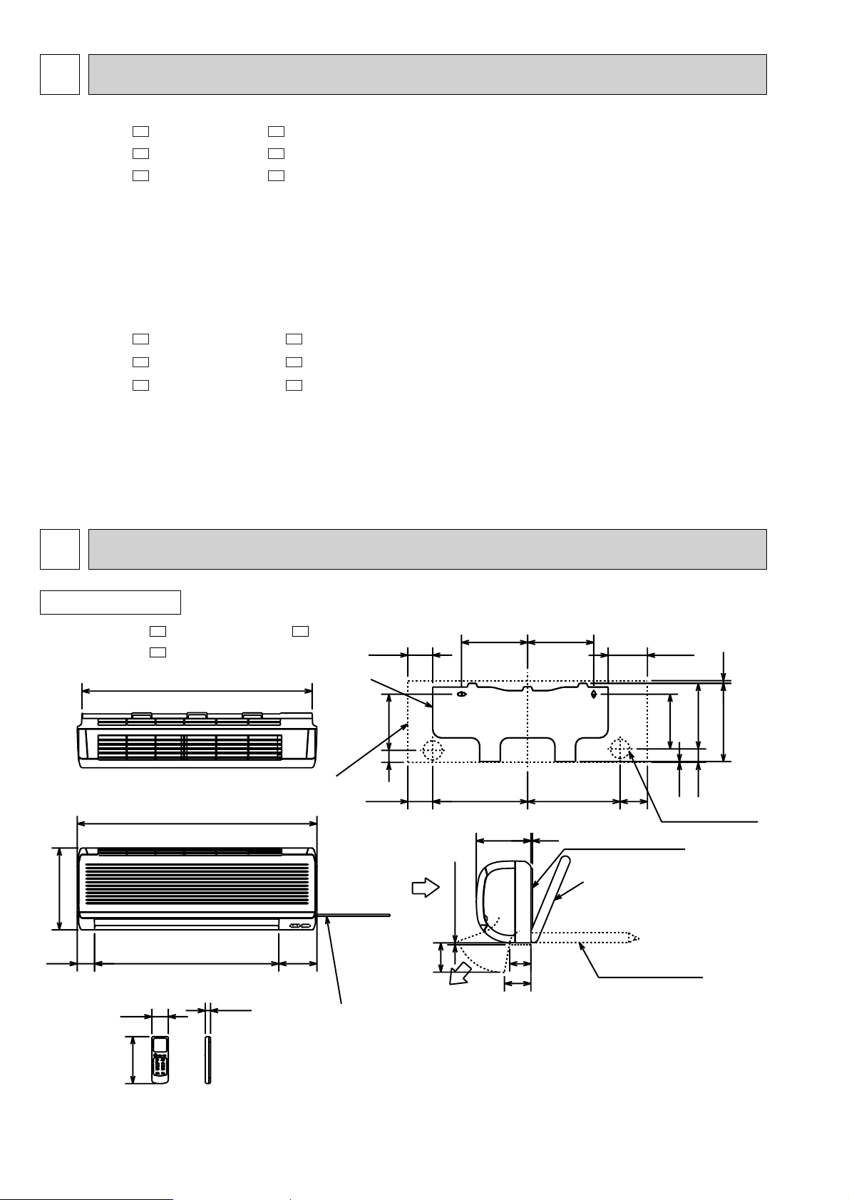
314.5323
2.5
186
191
223
266.5
46
41
225
84.5
9
133.5
84.5
225
93
183
13062560
275
815
17.5
783
72
7 or more
100
90
5
160
56
Liquid line {6.35-0.5m
Gas line {9.52-0.43m
Insulation {35 O.D
{19 I.D
Wireless remote controller
Power supply cord
Lead to right 1.0m
Lead to left 0.3m
Installation plate
Indoor unit
Wall hole {65
Installation plate
Drain hose {16
Insulation {28
Air out
{
Air in
1
TECHNICAL CHANGES
MSX-10NV- ➔ MSX-10NV-
MSX-18NV- ➔ MSX-18NVMSX-24NV- ➔ MSX-24NV-
1. Auto restart function has added.
2. INDOOR ELECTRONIC CONTROL P.C. BOARD has changed.
MSX-10NV- ➔ MSX-10NV22MSX-18NV- ➔ MSX-18NV22MSX-24NV- ➔ MSX-24NV22-
1. Indoor unit design has changed.
E2E1
E2E1
E2E1
E1E2
E1E2
E1E2
2
OUTLINES AND DIMENSIONS
INDOOR UNIT
MSX-05NV22- , MSX-09NV22MSX-12NV22-
E1
E1E1
Unit : mm
2
Page 3
3
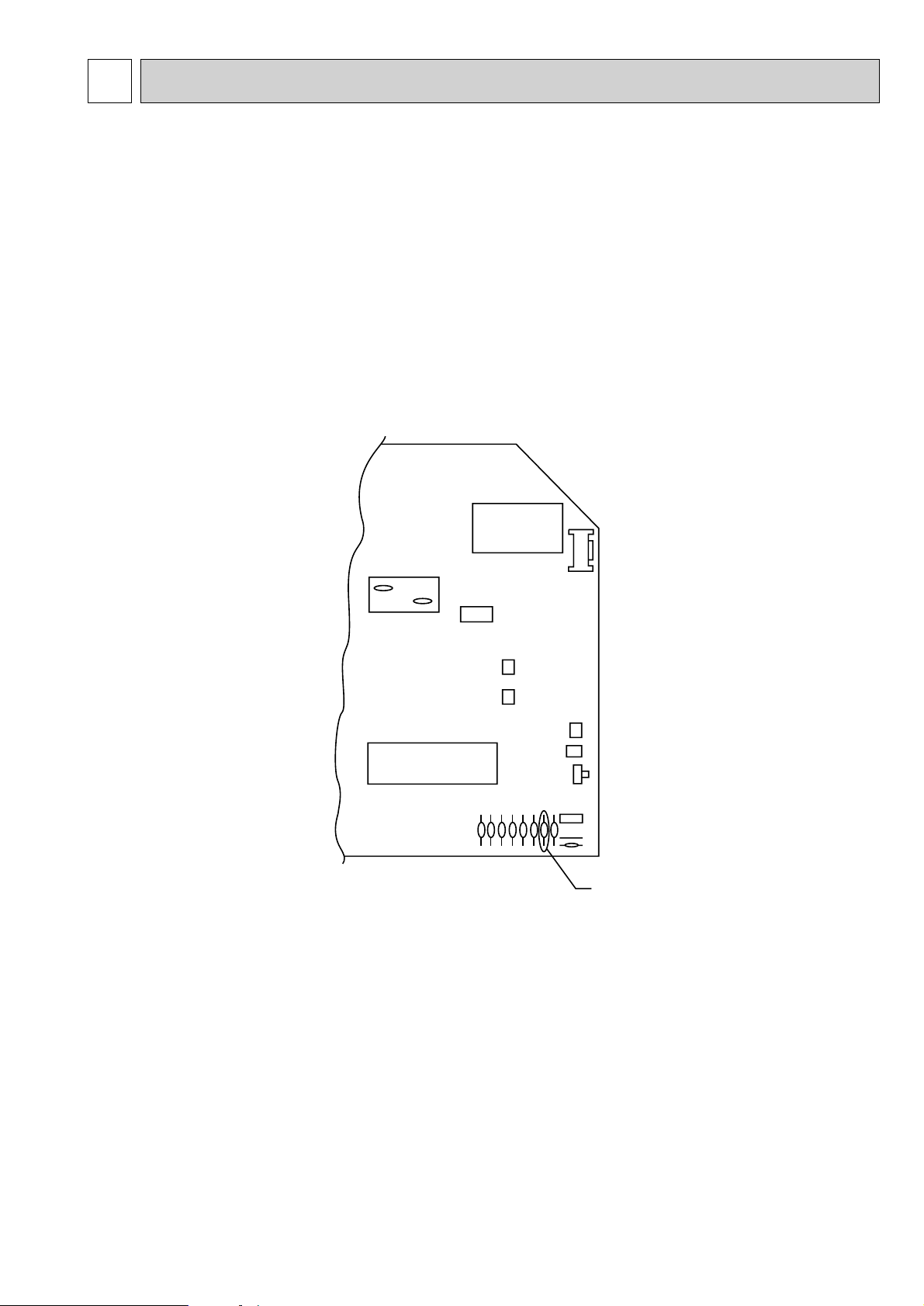
C11
52C
CN201
CN112
CN121SW
CN111
IC101
CN211
CN151
JR07
SERVICE FUNCTIONS
1. AUTO RESTART FUNCTION
When the indoor unit is controlled with the remote controller, the operation mode, set temperature, and the fan speed are
memorized by the indoor electronic control P.C.board. The “AUTO RESTART FUNCTION” sets to work the moment power
has restored after power failure.Then, the unit will restart automatically. However if the unit is operated in “I FEEL
CONTROL.” mode before power failure, the operation is not memorized. In “I FEEL CONTROL.” mode, the operation is
decided by the initial room temperature.
How to set “AUTO RESTART FUNCTION”
1Turn off the main power for the unit.
2Removed the electronic control P.C. board and the display P.C.board. (See page 39.)
3Cut the RESISTOR JR07 on the indoor electronic control P.C.board.
Operation
1If the main power (220-240V AC) has been cut, the operation settings remain.
2After the power is restored, the unit restarts automatically according to the memory.(However, it takes at least 3 minutes
for the compressor to start running.)
Note:
•The operation settings are memorized when 10 seconds have passed after the remote controller was operated.
•If main power is cut while AUTO START/STOP timer is active ,the timer setting is cancelled when auto restart function
works.
•If the unit has been off with the remote controller before power failure, the auto restart function does not works as the
power button of the remote controller is off.
•To prevent breaker off due to the rush of startting current, systematize other home appliance not to turn on at the same
time.
•When more than one air conditioners are connected under the same power system,compressor starting current as large
as that for all the compressors used flows at a time as soon as the units restart automatically.
Therefore, the specific counter-measures are required to prevent main voltage drop or the rush of starting current after
power failure by providing the system to allow the units to start in regular succession.
3
Page 4

4
PARTS LIST
INDOOR UNIT
STRUCTURAL PARTS
MSX-05NV - (WH)
MSX-09NV - (WH)
MSX-12NV - (WH)
6
E2
E2
E2
1
5
4
2
No.
1
2
3
4
5
6
Optional parts
3
E2
Q'ty / unit
MSX-
E2
09NV-
(WH)
1
1
2
1
1
2
MSX-
12NV-
(WH)
1
1
2
1
1
2
E2
Symbol
Parts No. Parts Name Remarks
E02 315 000
E02 316 000
E02 317 000
E02 151 010
E02 164 100
E02 166 234
E02 151 970
E02 166 067
FRONT PANEL
FRONT PANEL
FRONT PANEL
GRILLE
AIR FILTER
BOX
INSTALLATION PLATE
SCREW CAP
in Wiring
Diagram
MSX-
05NV-
(WH)
1
1
2
1
1
2 2PCS/SET
4
Page 5

INDOOR UNIT
STRUCTURAL PARTS
MSX-05NV22- (WH)
MSX-09NV22- (WH)
MSX-12NV22- (WH)
6
E1
E1
E1
1
5
4
2
No.
1
2
3
4
5
6
Optional parts
3
E1
Q'ty / unit
MSX-
09NV2-
(WH)
MSX-
E1
12NV2-
(WH)
E1
1
1
1
2
1
1
2
1
2
1
1
2
Symbol
Parts No. Parts Name Remarks
in Wiring
Diagram
E02 349 000
E02 350 000
E02 351 000
E02 339 010
E02 164 100
E02 166 234
E02 151 970
E02 166 067
FRONT PANEL
FRONT PANEL
FRONT PANEL
GRILLE
AIR FILTER
BOX
INSTALLATION PLATE
SCREW CAP
MSX-
05NV2-
(WH)
1
1
2
1
1
2 2PCS/SET
5
Page 6

INDOOR UNIT
No.
Parts No. Parts Name Remarks
Q'ty / unit
MSX-05/09
MSX-12
Symbol
in Wiring
Diagram
Part number that are circled not shown in the figure.
1
2
3
4
5
6
7
8
9
10
11
12
13
14
15
16
17
18
19
E02 199 235
E02 166 040
E02 141 702
E02 151 303
E02 151 300
E02 151 505
E02 151 302
E02 151 509
E02 151 308
E02 151 307
E02 211 375
E02 211 452
E02 281 452
E02 152 395
E02 127 382
E02 164 081
E02 151 350
E02 085 385
E02 001 504
E02 199 520
NOZZLE(WH)
VANE(WH)
DRAIN HOSE
VANE MOTOR
INDOOR FAN MOTOR
RUBBER MOUNT
LINE FLOW FAN
BEARING MOUNT
ROOM TEMPERATURE THERMISTOR
INDOOR COIL THERMISTOR
TERMINAL BLOCK
ELECTRONIC CONTROL P.C.BOARD
ELECTRONIC CONTROL P.C.BOARD
POWER SUPPLY CORD
FUSE
ELECTRICAL BOX
INDOOR FAN CAPACITOR
VARISTOR
SLEEVE BEARING
FAN GUARD
1
1
1
1
1
2
1
1
1
1
1
1
1
1
1
1
1
1
1
1
1
1
1
1
2
1
1
1
1
1
1
1
1
1
1
1
1
1
RC4V19 2PCS/SET
AUTO RESTART
AUTO RESTART
3.15A
1.5µF/440VAC
MV
MF
RT11
RT12
TB
F11
C11
NR11
NV2-
E1
(WH)
NV-
E2
(WH)
NV-
E2
(WH)
NV2-
E1
(WH)
1
1
1
1
1
2
1
1
1
1
1
1
1
1
1
1
1
1
1
1
1
1
1
1
2
1
1
1
1
1
1
1
1
1
1
1
1
1
ELECTRICAL PARTS
MSX-05NV - (WH) MSX-09NV - (WH) MSX-12NV - (WH)
MSX-05NV22- (WH) MSX-09NV22- (WH) MSX-12NV22- (WH)
E2E2E2
E1E1E1
15
8
7
9
11
10
18
3
6
5
12
1
2
4
13
6
Page 7

INDOOR UNIT
HEAT EXCHANGER
MSX-05NV - (WH)
MSX-09NV - (WH)
MSX-12NV - (WH)
MSX-05NV22- (WH)
MSX-09NV22- (WH)
MSX-12NV22- (WH)
E2
E2
E2
E1
E1
E1
1
No.
1
2
3
3
2
Q'ty / unit
Symbol
Parts No. Parts Name Remarks
in Wiring
Diagram
E02 151 620
E02 339 620
E02 155 620
E02 336 620
E02 151 666
E02 155 666
E02 151 667
INDOOR HEAT EXCHANGER
INDOOR HEAT EXCHANGER
INDOOR HEAT EXCHANGER
INDOOR HEAT EXCHANGER
UNION(GAS)
UNION(GAS)
UNION(LIQUID)
MSX-05/09
E2
NV-
(WH)
1
1
1
NV2-
(WH)
1
1
1
MSX-12
NV-
(WH)
E2
NV2-
(WH)
E1
E1
Remarks
1
1
{ 9.52
1
1
1
1
{ 12.7
{ 6.35
7
Page 8

HEAD OFFICE MITSUBISHI DENKI BLDG.MARUNOUCHI TOKYO100 TELEX J24532 CABLE MELCO TOKYO
CC
Copyright 1997 MITSUBISHI ELECTRIC ENGINEERING CO.,LTD.
Issued in Jan. 1998 NO. OB221 128
Printed in Japan
New publication, effective Jan. 1998.
Specifications subject to change without notice.
 Loading...