

Mitsubishi MSH-XV07UV-E1, MSH-XV09UV-E1, MSH-XV12UV-E1, MUH-XV07UV-E1, MUH-XV09UV-E1 Service Manual
...Page 1
SERVICE MANUAL
SPLIT-TYPE, HEAT PUMP AIR CONDITIONERS
Wireless type
Models
No. OB294
MSH-XV07UV MSH-XV09UV MSH-XV12UV -
(WH)
·MUH-XV07UV -
(WH)
·MUH-XV09UV -
(WH)
·MUH-XV12UV -
CONTENTS
1. PART NAMES AND FUNCTIONS······················3
2. SPECIFICATION·················································5
3. NOISE CRITERIA CURVES·······························7
4. OUTLINES AND DIMENSIONS························ 8
5. WIRING DIAGRAM ··········································10
6. REFRIGERANT SYSTEM DIAGRAM··············11
7. PERFORMANCE CURVES······························13
8. MICROPROCESSOR CONTROL ····················29
9. SERVICE FUNCTIONS ····································38
10. TROUBLESHOOTING ······································40
11. DISASSEMBLY INSTRUCTIONS·····················51
12. PARTS LIST······················································55
E1E1
E1E1
E1E1
Page 2

Page 3
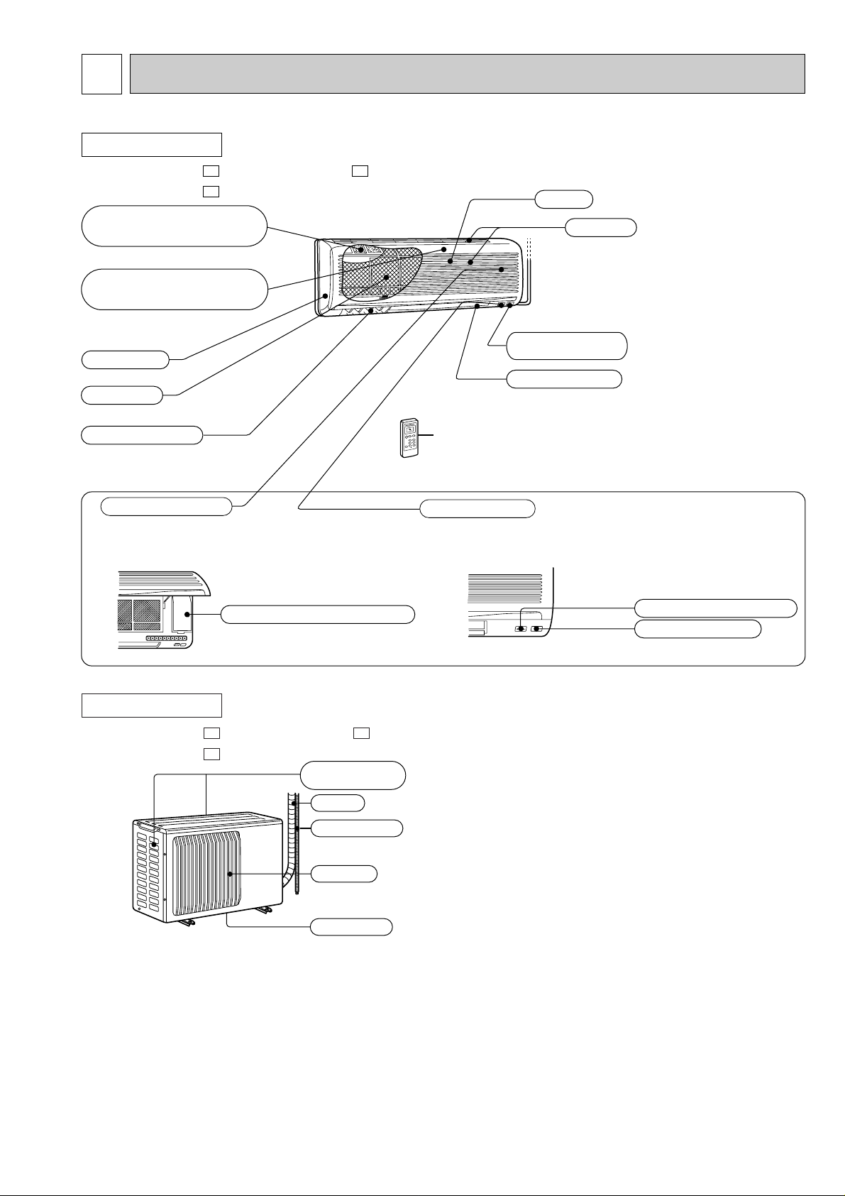
1
Operation section
Horizontal vane
Air filter
Deodorizing filter
(Gray sponge type)
Vertical vanes
Air inlet
Grille
Remote control
receiving section
Remote controller
Display section
(When the grille is opened)
Operation indicator lamp
Receiving section
Air cleaning filter
(White bellows type)
Emergency operation switch
Front panel
Air inlet
Piping
Drain hose
Air outlet
Drain outlet
(back and side)
PART NAMES AND FUNCTIONS
INDOOR UNIT
MSH-XV07UV - MSH-XV12UV MSH-XV09UV -
E1
E1E1
OUTDOOR UNIT
MUH-XV07UV - MUH-XV12UV MUH-XV09UV -
E1
E1E1
3
Page 4
ON/OFF
RESET
TOO
WARM
TOO
COOL
ECONO COOL
POWERFUL COOL
SELECT
FAN
VANE
TIMEMODE
h
I FEEL
COOL
DRY
HEAT
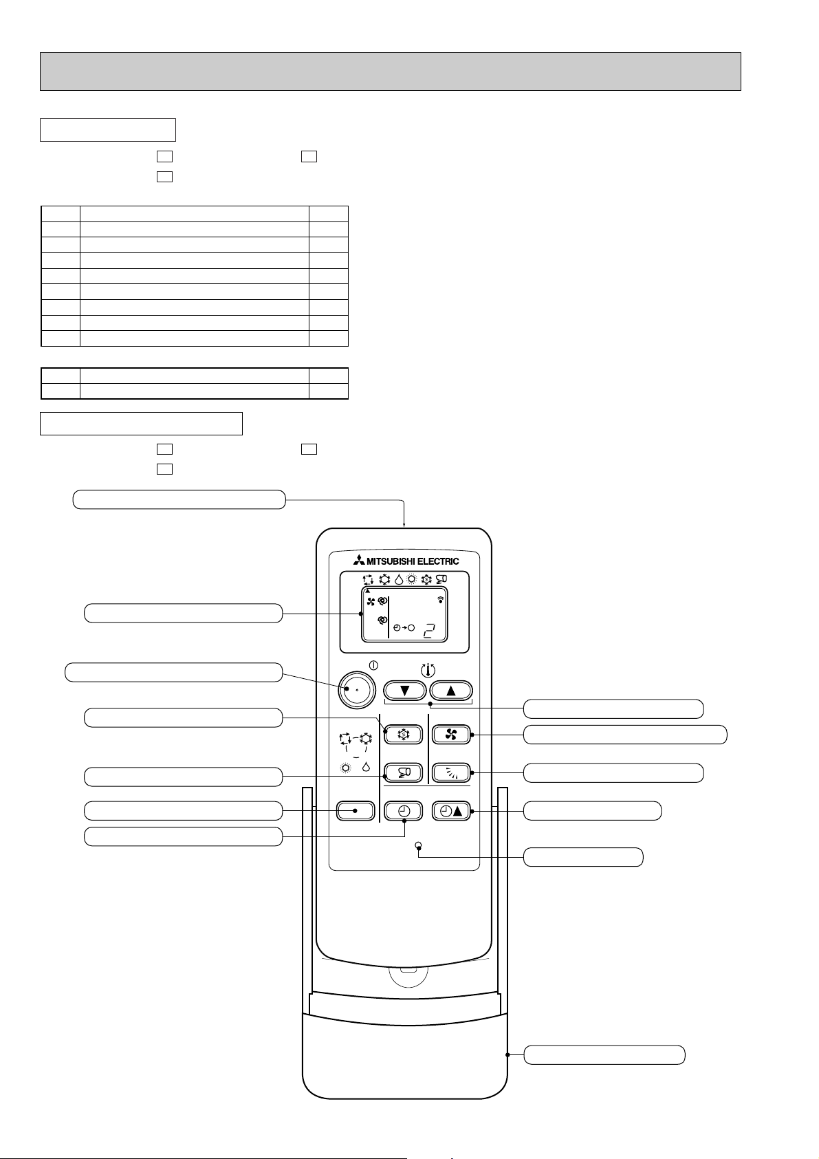
Signal transmitting section
Operation display section
TEMPERATURE buttons
VANE CONTROL button
TIME SET button
RESET button
FAN SPEED CONTROL button
ECONO COOL button
POWERFUL COOL button
OPERATION SELECT button
TIMER MODE SELECT button
OPERATE/STOP (ON/OFF) button
Remote controller holder
1
5
1
2
2
1
1
1
1
1
2
3
4
5
6
7
8
9
Installation plate
Installation plate fixing screw 4 x 25 mm
Remote controller holder
Fixing screw for 3 3.5 x 16 mm (Black)
Battery (AAA) for remote controller
Wireless remote controller
Felt tape (Used for left or left-rear piping)
Deodorizing filter
Air cleaning filter
<Indoor unit>
1
2
0
1
Drain socket
Drain cap
<Outdoor unit>
ACCESSORIES
MSH-XV07UV - MSH-XV12UV MSH-XV09UV -
E1
REMOTE CONTROLLER
MSH-XV07UV - MSH-XV12UV MSH-XV09UV -
E1
E1E1
E1E1
4
Page 5
2
Indoor model
Function
Power supply
Capacity
Dehumidification
Air flow
(High/Med.W/LowW)
Power outlet
Running current
Power input
Auxiliary heater
Power factor
Starting current
Fan motor current
Model
Winding
resistance(at20:)
Dimensions WOHOD
Weight
Air direction
Sound level
(High/Med.W/LowW)
Fan speed
(High/Med.W/LowW)
Fan speed regulator
Thermistor RT11(at25:)
Thermistor RT12(at25:)
Outdoor model
Air flow
Compressor motor current
Fan motor current
Model
Output
Winding
resistance(at20:)
Model
Winding
resistance(at20:)
Dimensions WOHOD
Weight
Sound level
Fan speed
Fan speed regulator
Refrigerant filling
capacity(R22)
Refrigerating oil(Model)
Thermistor
RT61(at0:)
kW
R/h
K /h
A
A
W
A(kW)
%
A
A
"
mm
kg
dB
rpm
k"
k"
K /h
A
A
W
"
"
mm
kg
dB
rpm
kg
cc
k"
MSH-XV07UV -
E1
Single phase
220-240V, 50Hz
10
—
19
0.17
RC4V19-LA
WHT-BLK 413
BLK-RED 334
850O278O191
9
5
36/31
W
/26
W
3
10
10
MUH-XV07UV -
E1
1,620-1,752
0.21-0.22
RH-130VGCT
650
C-R 4.18
C-S 5.76
RA6V23-FB
WHT-BLK 353
BLK-RED 321
780o540o255
33
49
710-760
1
0.77
300 (MS56)
33.18
Cooling
2.1
0.8
474/390
W
/306
W
3.29-3.15
710-740
98-98
2.96-2.84
960/810
W
/670
W
2.91-2.76
Heating
2.4
—
474/390
W
/306
W
3.11-2.98
670-700
98-98
3.58-3.43
960/840
W
/730
W
2.73-2.59
Electrical
data
Fan
motor
Special
remarks
Compressor
Electrical
data
Fan
motor
Special
remarks
Capacity
Coefficient of performance(C.O.P)
Capacity
MSH-XV09UV -
E1
Single phase
220-240V, 50Hz
10
—
25
0.17
RC4V19-LA
WHT-BLK 413
BLK-RED 334
850O278O191
9
5
39/34
W
/28
W
3
10
10
MUH-XV09UV -
E1
1,620-1,752
0.21-0.22
RH-174VGCT
800
C-R 3.30
C-S 6.01
RA6V23-FB
WHT-BLK 353
BLK-RED 321
780o540o255
33
49
710-760
1
0.87
300 (MS56)
33.18
Cooling
2.5
1.1
504/408
W
/306
W
4.36-4.21
940-970
98-96
2.66-2.58
1,010/840
W
/670
W
3.98-3.82
Heating
3.1
—
534/438
W
/342
W
4.36-4.21
940-970
98-96
3.30-3.20
1,060/890W/730
W
3.98-3.82
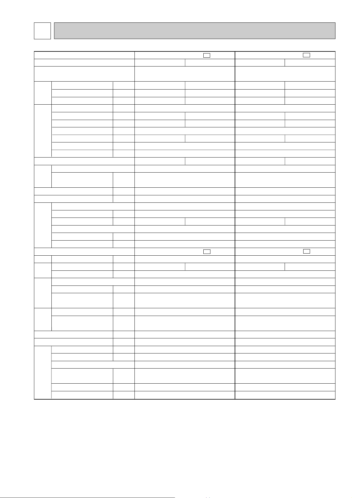
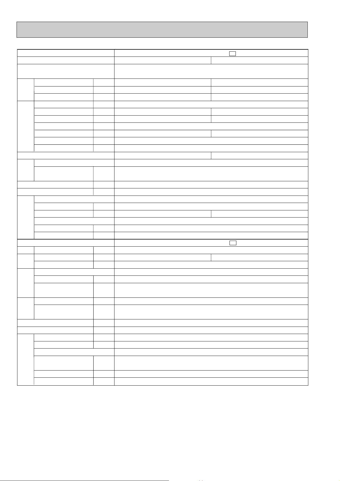
SPECIFICATION
NOTE: Test conditions are based on ISO5151.
Cooling : Indoor DB27°C / WB19°C Heating : Indoor DB20°C
Outdoor DB35°C / WB(24°C) Outdoor DB 7°C / WB 6°C
Indoor-Outdoor piping length 5m
W Reference value
5
Page 6
Indoor model
Function
Power supply
Capacity
Dehumidification
Air flow
(High/Med.W/LowW)
Power outlet
Running current
Power input
Auxiliary heater
Power factor
Starting current
Fan motor current
Model
Winding
resistance(at20:)
Dimensions WOHOD
Weight
Air direction
Sound level
(High/Med.W/LowW)
Fan speed
(High/Med.W/LowW)
Fan speed regulator
Thermistor RT11(at25:)
Thermistor RT12(at25:)
Outdoor model
Air flow
Compressor motor current
Fan motor current
Model
Output
Winding
resistance(at20:)
Model
Winding
resistance(at20:)
Dimensions WOHOD
Weight
Sound level
Fan speed
Fan speed regulator
Refrigerant filling
capacity(R22)
Refrigerating oil(Model)
Thermistor
RT61(at0:)
kW
R/h
K /h
A
A
W
A(kW)
%
A
A
"
mm
kg
dB
rpm
k"
k"
K /h
A
A
W
"
"
mm
kg
dB
rpm
kg
cc
k"
Electrical
data
Fan
motor
Special
remarks
Compressor
Electrical
data
Fan
motor
Special
remarks
Capacity
Coefficient of performance(C.O.P)
Capacity
MSH-XV12UV -
E1
Single phase
220-240V, 50Hz
10
—
35
0.19
RC4V19-KA
WHT-BLK 316
BLK-RED 299
850O278O191
9
5
42/37
W
/32
W
3
10
10
MUH-XV12UV -
E1
1,656-1,758
0.29-0.32
RH-231VHAT
1,100
C-R 2.13
C-S 3.91
RA6V33-DB
WHT-BLK 301
BLK-RED 332
780o540o255
38
49
810-840
1
1.10
520 (MS56)
33.18
Cooling
3.4
1.6
564/474
W
/384
W
5.92-6.02
1,250-1,330
96-92
2.72-2.56
1,110/950
W
/800
W
5.44-5.51
Heating
4.05
—
600/510
W
/432
W
6.34-6.43
1,340-1,420
96-92
3.02-2.85
1,160/1,020
W
/880
W
5.86-5.92
NOTE: Test conditions are based on ISO5151.
Cooling : Indoor DB27°C / WB19°C Heating : Indoor DB20°C
Indoor-Outdoor piping length 5m
W Reference value
Outdoor DB35°C / WB(24°C) Outdoor DB 7°C / WB 6°C
6
Page 7
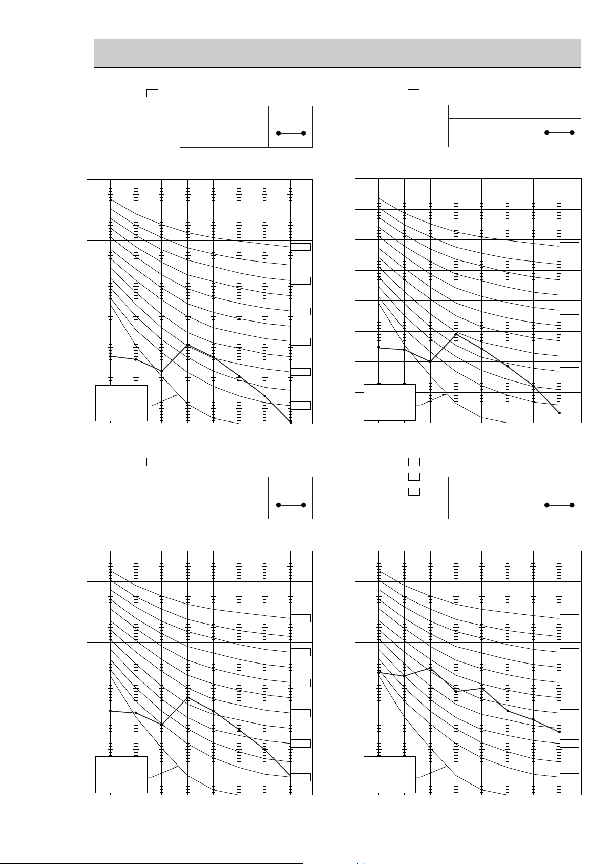
3
NOISE CRITERIA CURVES
MSH-XV07UV -
E1
NOTCH
High
SPL(dB(A)) LINE
36
Test conditions,
Cooling : Dry-bulb temperature 27: Wet-bulb temperature 19:
Heating : Dry-bulb temperature 20:
90
80
70
60
50
40
30
APPROXIMATE
20
THRESHOLD OF
HEARING FOR
CONTINUOUS
OCTAVE BAND SOUND PRESSURE LEVEL, dB re 0.0002 MICRO BAR
NOISE
10
63 125 250 500 1000 2000 4000 8000
BAND CENTER FREQUENCIES, Hz
MSH-XV09UV -
Test conditions,
Cooling : Dry-bulb temperature 27: Wet-bulb temperature 19:
Heating : Dry-bulb temperature 20:
NC-70
NC-60
NC-50
NC-40
NC-30
NC-20
OCTAVE BAND SOUND PRESSURE LEVEL, dB re 0.0002 MICRO BAR
E1
NOTCH
SPL(dB(A)) LINE
High
90
80
70
60
50
40
30
APPROXIMATE
20
THRESHOLD OF
HEARING FOR
CONTINUOUS
NOISE
10
63 125 250 500 1000 2000 4000 8000
BAND CENTER FREQUENCIES, Hz
39
NC-70
NC-60
NC-50
NC-40
NC-30
NC-20
MSH-XV12UV -
E1
NOTCH
High
SPL(dB(A)) LINE
42
Test conditions,
Cooling : Dry-bulb temperature 27: Wet-bulb temperature 19:
Heating : Dry-bulb temperature 20:
90
80
70
60
50
40
30
MUH-XV07UV MUH-XV09UV MUH-XV12UV -
Test conditions,
Cooling : Dry-bulb temperature 35: Wet-bulb temperature (24:)
Heating : Dry-bulb temperature 7: Wet-bulb temperature 6:
NC-70
NC-60
NC-50
NC-40
NC-30
E1
E1
E1
NOTCH
High
SPL(dB(A)) LINE
49
90
80
70
NC-70
60
NC-60
50
NC-50
40
NC-40
30
NC-30
APPROXIMATE
20
THRESHOLD OF
HEARING FOR
CONTINUOUS
OCTAVE BAND SOUND PRESSURE LEVEL, dB re 0.0002 MICRO BAR
NOISE
10
63 125 250 500 1000 2000 4000 8000
BAND CENTER FREQUENCIES, Hz
NC-20
APPROXIMATE
20
THRESHOLD OF
HEARING FOR
CONTINUOUS
OCTAVE BAND SOUND PRESSURE LEVEL, dB re 0.0002 MICRO BAR
NOISE
10
63 125 250 500 1000 2000 4000 8000
BAND CENTER FREQUENCIES, Hz
7
NC-20
Page 8
4
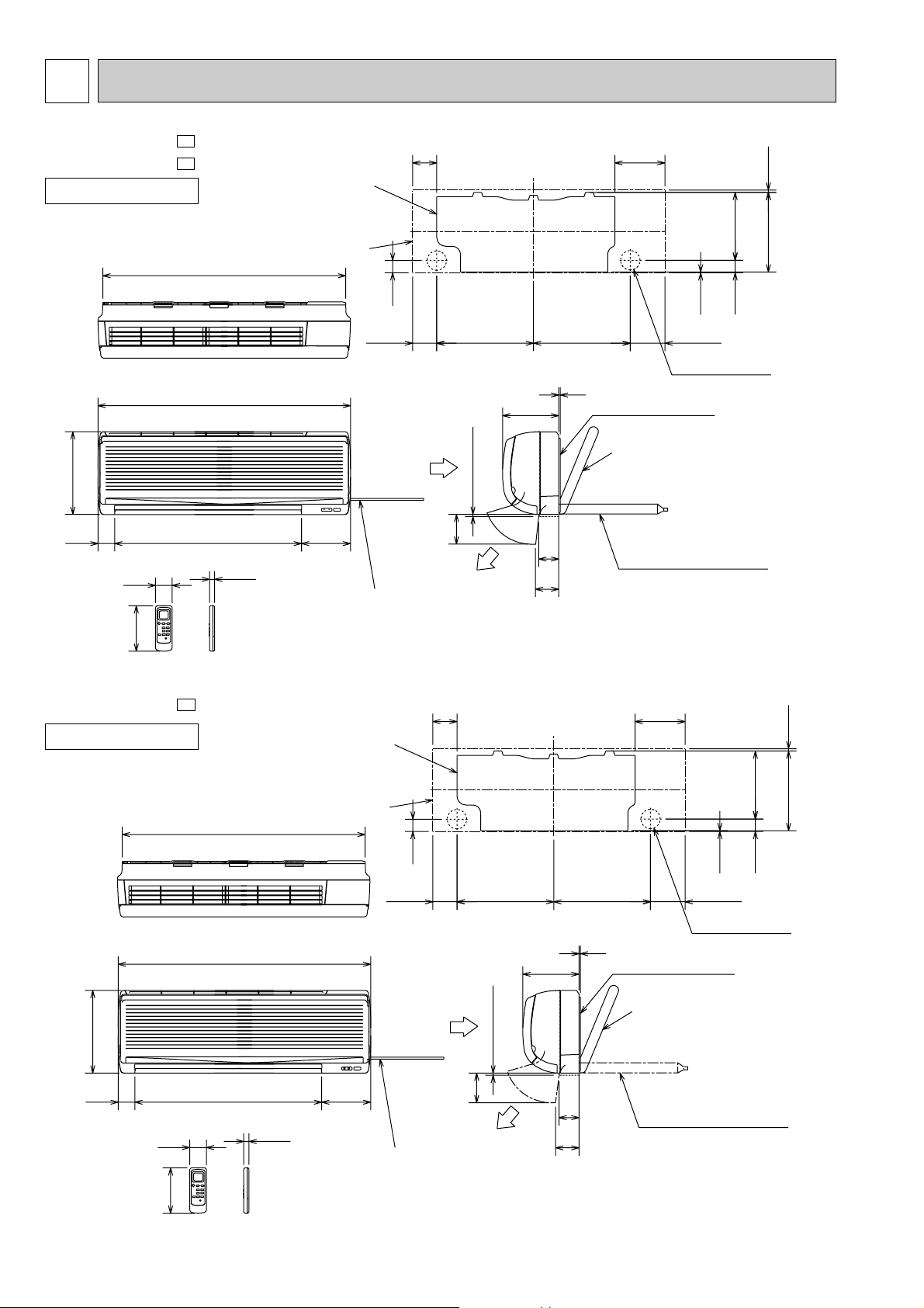
OUTLINES AND DIMENSIONS
MSH-XV07UV MSH-XV09UV -
INDOOR UNIT
Unit: mm
E1
E1
Installation plate
Indoor unit
818
82 169
231.5
271 4.5
278
57
140
Wireless remote controller
MSH-XV12UV -
INDOOR UNIT
41
326 326
67
78
5
Installation plate
Liquid line [6.35-0.5m
Gas line [9.52-0.43m
{
Insulation [37 O.D
Drain hose [16
(Connected part O.D)
Insulation [28
850
Air in
7 or more
16562956
17.5
Power supply cord
Lead to right 1.0m
Lead to left 0.3m
E1
Installation plate
100
Air out
82
189
116.581.5
Wall hole [65
[21 I.D
169
2.5
42
278
818
850
57
140
Wireless remote controller
17.5
Indoor unit
16562956
Power supply cord
Lead to right 1.0m
Lead to left 0.3m
41
Air in
326 326
189
or more
7
100
Air out
67
78
5
Installation plate
Liquid line [6.35-0.5m
Gas line [12-0.43m
{
Insulation [37 O.D
[21 I.D
Drain hose [16
(Connected part O.D)
Insulation [28
231.5
42
2.5
116.581.5
Wall hole [65
271 4.5
8
Page 9
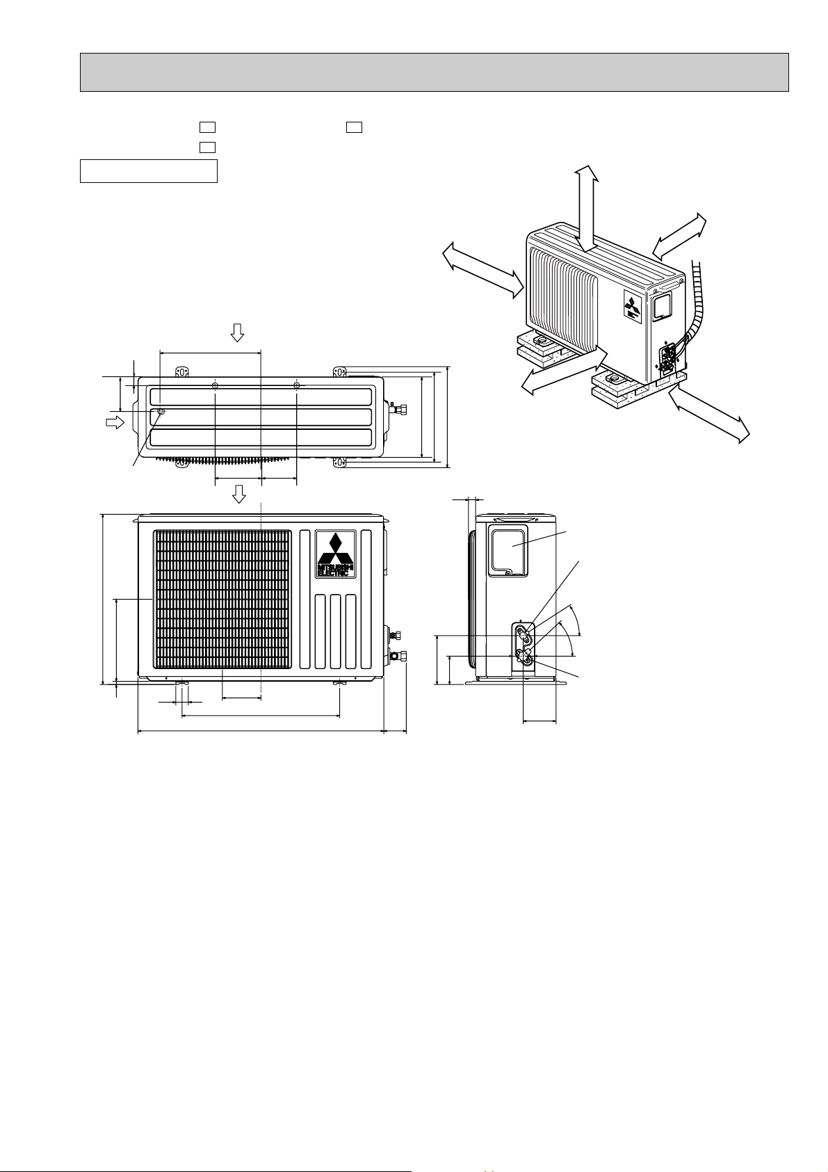
MUH-XV07UV - MUH-XV12UV MUH-XV09UV -
E1
OUTDOOR UNIT
Unit: mm
E1E1
REQUIRED SPACE
32
109
Air in
Drainage
3holes [33
540
260
320
Air in
147
110
Airout
100mm or more
320
285
255
25
100mm or more
400mm or more
Service panel
Liquid refrigerant
pipe joint
Refrigerant pipe
(flared) [6.35
35-
43-
100mm or more
350mm or more
10
40
122
500
780
74
155
90
104
Gas refrigerant
pipe joint
Refrigerant pipe
(flared) [9.52 (MUH-XV07/09UV
[12.7 (MUH-XV12UV
)
)
9
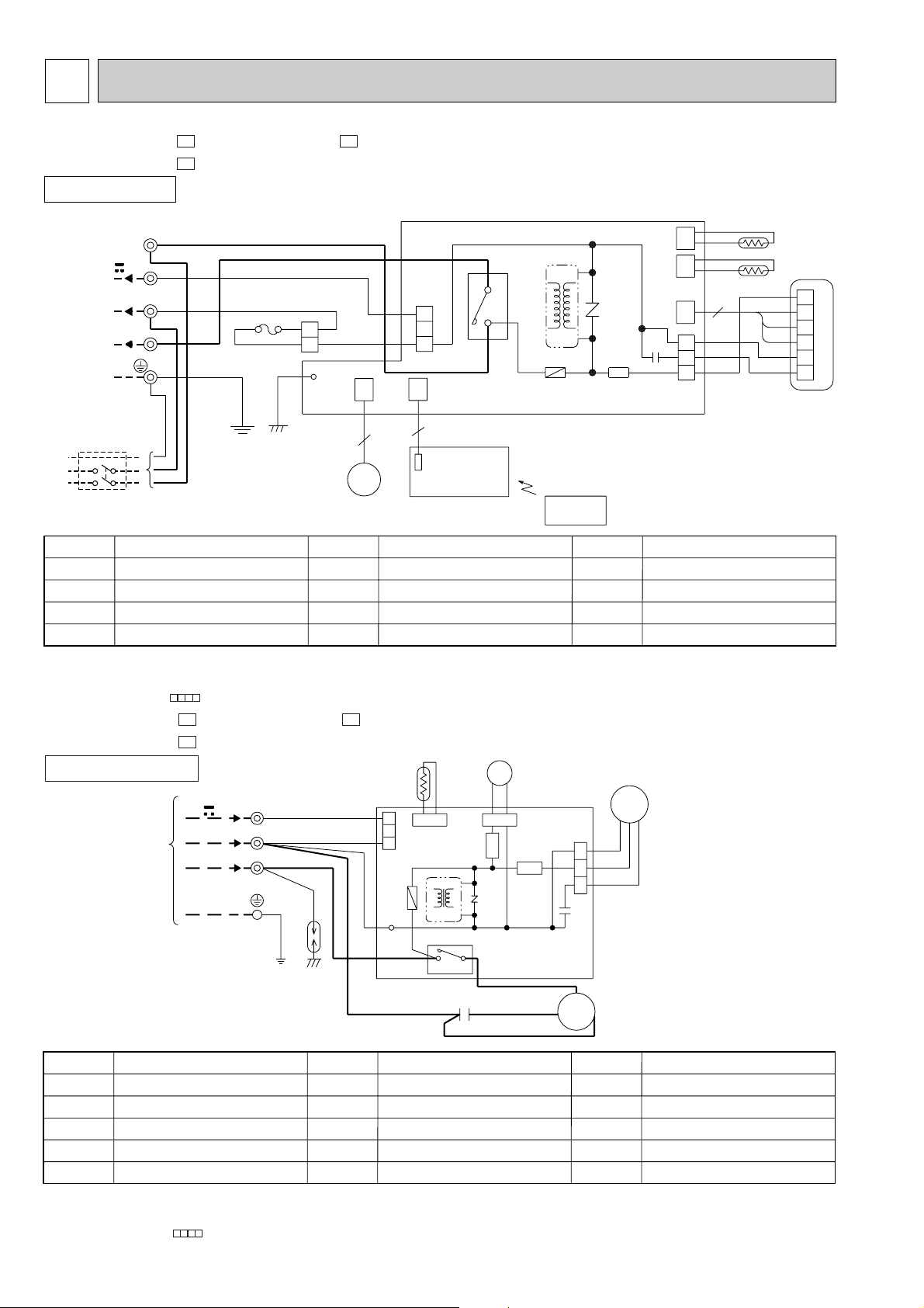
Page 10
5
SYMBOL
SR141
TB
T11
52C
SYMBOL
MV
NR11
RT11
RT12
SYMBOL
C11
F11
F12
MF
NAME
NAME NAME
INDOOR FAN CAPACITOR
FUSE(3.15A)
THERMAL FUSE(93:)
INDOOR FAN MOTOR(INNER FUSE)
VANE MOTOR
VARISTOR
ROOM TEMPERATURE THERMIST OR
INDOOR COIL THERMISTOR
SOLID STATE RELAY
TERMINAL BLOCK
TRANSFORMER
CONTACTOR
~/N 220-240V
50Hz
PE
CIRCUIT BREAKER
220-240V~
12V
CN
151
ELECTRONIC CONTROL P.C. BOARD
5
REMOTE
CONTROLLER
POWER MONITOR,
RECEIVER
P.C. BOARD
MV
5
TO OUTDOOR
UNIT
CONNECTING
C11
SR141
5
1
CN211
3
T11
RED
WHT
6
5
4
3
2
1
MF
RT12
RT11
CN
112
111
CN
BLK
BRN
GRY
YLW
121
CN
3
NR11
F11
52C
GRN/YLW
GRN/YLW
BLU
BLU
BLU
BLU
WHT
F12
1
2
CN201
1
2
3
4
3
BLU
3
2
BRN
52C
TB
N
L
RED
BRN
CN
101
POWER
SUPPLY
CORD
GRN
LD103
WIRING DIAGRAM
MSH-XV07UV - MSH-XV12UV MSH-XV09UV -
E1
INDOOR UNIT
E1E1
MODELS WIRING DIAGRAM
NOTE:1. About the outdoor side electric wiring refer to the outdoor unit electric wiring diagram for servicing.
2. Use copper conductors only. (For field wiring)
3. Symbols below indicate.
/: Terminal block, : Connector
MUH-XV07UV - MUH-XV12UV MUH-XV09UV -
E1
OUTDOOR UNIT
TB
12V
220-240V~
FROM INDOOR UNIT
CONNECTING
SYMBOL
C1
C65
DSAR
F61
MC
NOTE:1. About the indoor side electric wiring refer to the indoor unit electric wiring diagram for servicing.
NAME
COMPRESSOR CAPACITOR
OUTDOOR FAN CAPACITOR
SURGE ABSORBER
FUSE(2A)
COMPRESSOR(INNER PROTECTOR)
2.Use copper conductors only. (For field wiring)
3. Symbols below indicate.
/: Terminal block, : Connector
3
N
2
E1E1
RED
BLU
WHT
WHT
DSAR
BLU
BLU
SYMBOL
MF
NR61
RT61
SR61,SR62
T61
MODELS WIRING DIAGRAM
RT61
1
CN661
2
3
CN730
F61
T61
TAB20
OUTDOOR FAN MOTOR(INNER FUSE)
VARISTOR
DEFROST THERMISTOR
SOLID STATE RELAY
TRANSFORMER
52C
4
10
21S4
CN721
SR62
NR61
3
DEICER P.C.BOARD
C1
RED
BLK
NAME NAME
CN711
1
SR61
WHT
2
3
C65
MC
S
SYMBOL
MF
WHT
BLK
RED
C
R
TB
21S4
52C
TERMINAL BLOCK
R.V. COIL
COMPRESSOR CONTACTOR
SG79J411H01
VG79B112H01
Page 11
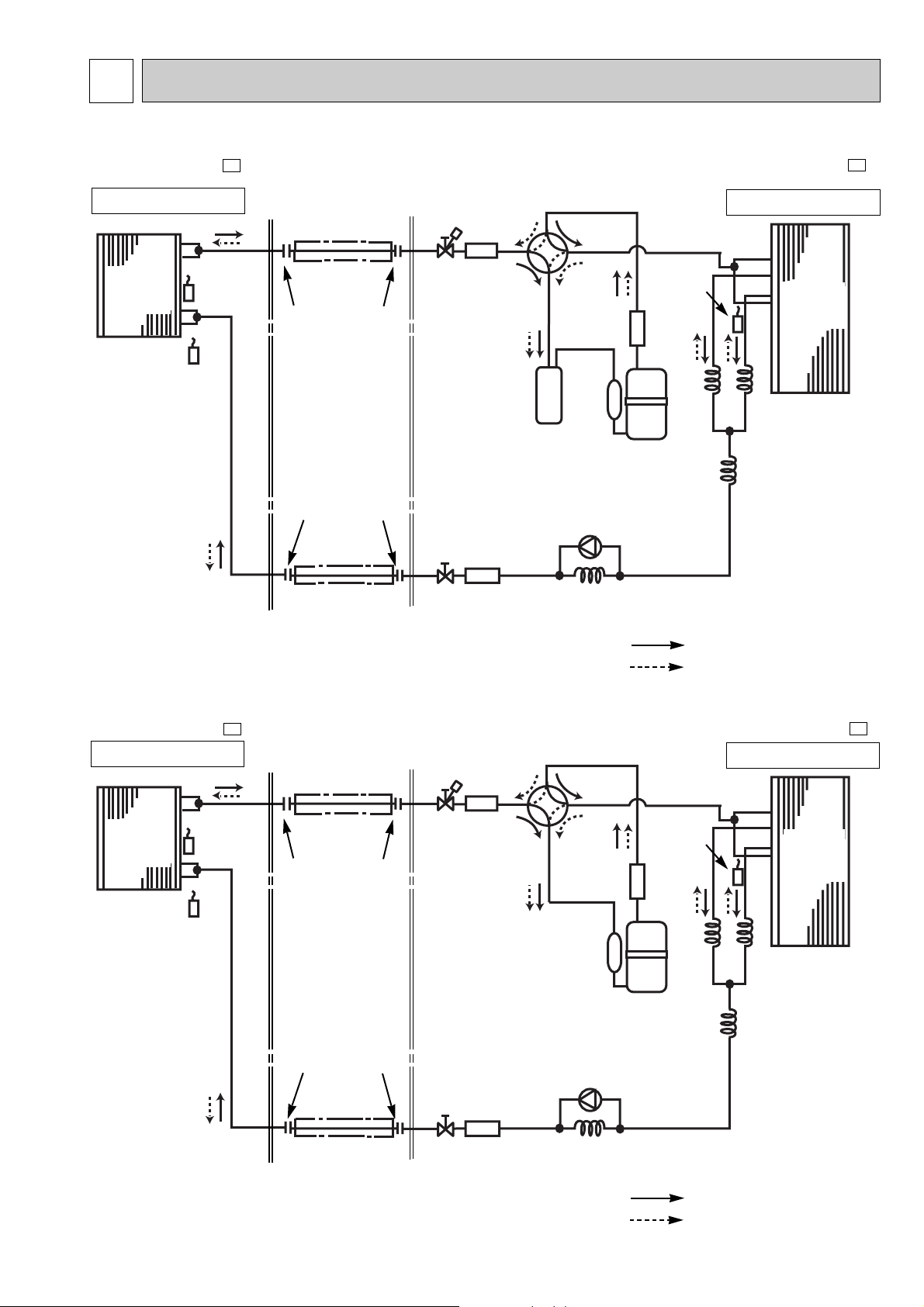
6
REFRIGERANT SYSTEM DIAGRAM
MSH-XV07UV -
Unit:mm
E1
MUH-XV07UV -
E1
INDOOR UNIT
Indoor
heat
exchanger
Room temperature
thermistor
RT11
Indoor coil
thermistor
RT12
Refrigerant pipe [ 9.52
(with heat insulator)
Flared connection
Flared connection
Refrigerant pipe [6.35
(with heat insulator)
Muffler
Stop valve
(with service
port)
Strainer
Stop valve
4-way valve
Accumulator
Check valve
Capillary tube
[3.0O[1.4O600
Strainer
Compressor
Defrost
thermistor
RT61
Refrigerant flow in cooling
Refrigerant flow in heating
OUTDOOR UNIT
Outdoor
heat
exchanger
Capillary tube
[3.0O[1.4O800
(2 pcs)
Capillary tube
[3.0O[1.6O600
R.V. coil
heating ON
cooling OFF
MSH-XV09UV -
INDOOR UNIT
Indoor
heat
exchanger
Room temperature
thermistor
RT11
Indoor coil
thermistor
RT12
E1
Refrigerant pipe [ 9.52
(with heat insulator)
Flared connection
Flared connection
Refrigerant pipe [6.35
(with heat insulator)
Muffler
Stop valve
(with service
port)
Strainer
Stop valve
4-way valve
Strainer
Compressor
Check valve
Capillary tube
[3.0O[1.4O510
Defrost
thermistor
RT61
Refrigerant flow in cooling
Refrigerant flow in heating
Unit:mm
MUH-XV09UV -
OUTDOOR UNIT
Outdoor
heat
exchanger
Capillary tube
[3.0O[1.4O800
(2 pcs)
Capillary tube
[3.0O[1.6O450
R.V. coil
heating ON
cooling OFF
E1
11
Page 12
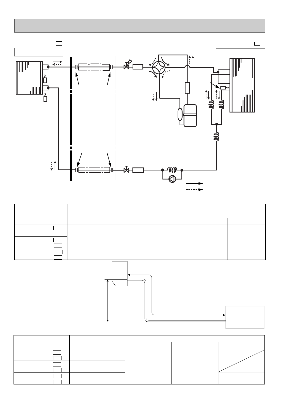
Indoor
unit
w Max. Height
difference 5m
Height difference should be within
5m regardless of which unit,
indoor or outdoor position is high.
Outdoor unit
Refrigerant Piping
Max.length
A
Refrigerant piping
Max. length : m
A
10
15
Indoor unit
Gas 0.43
Liquid 0.5
Gas
9.52
12.7
Liquid
6.35
Outdoor unit
Gas 0
Liquid 0
Piping size O.D : mm Length of connecting pipe : m
Model
MSH-XV07UV - E1
MUH-XV07UV - E1
MSH-XV09UV - E1
MUH-XV09UV - E1
MSH-XV12UV - E1
MUH-XV12UV - E1
Calculation : Xg=50g/mx(Refrigerant piping length(m)-7)
MSH-XV07UV -
E1
MUH-XV07UV - E1
MSH-XV09UV - E1
MUH-XV09UV - E1
MSH-XV12UV - E1
MUH-XV12UV - E1
Outdoor unit precharged
770
870
1100
15m
400
7m
0
10m
150
Model
Refrigerant piping length (one way)
MSH-XV12UV -
INDOOR UNIT
E1
Refrigerant pipe [12.7
(with heat insulator)
Muffler
4-way valve
Unit:mm
MUH-XV12UV -
OUTDOOR UNIT
E1
Indoor
heat
exchanger
Room temperature
thermistor
RT11
Indoor coil
thermistor
RT12
Flared connection
Flared connection
Refrigerant pipe [6.35
(with heat insulator)
MAX. REFRIGERANT PIPING LENGTH
Stop valve
(with service port)
Strainer
Stop valve
Strainer
Compressor
Capillary tube
[3.0O[1.6O700
Check valve
Defrost
thermistor
RT61
Capillary tube
[3.0O[1.4O500(2pcs)
Capillary tube
[3.0O[1.8O300
R.V. coil
heating ON
cooling OFF
Refrigerant flow in cooling
Refrigerant flow in heating
Outdoor
heat
exchanger
MAX. HEIGHT DIFFERENCE
ADDITIONAL REFRIGERANT CHARGE(R22 : g)
12
Page 13

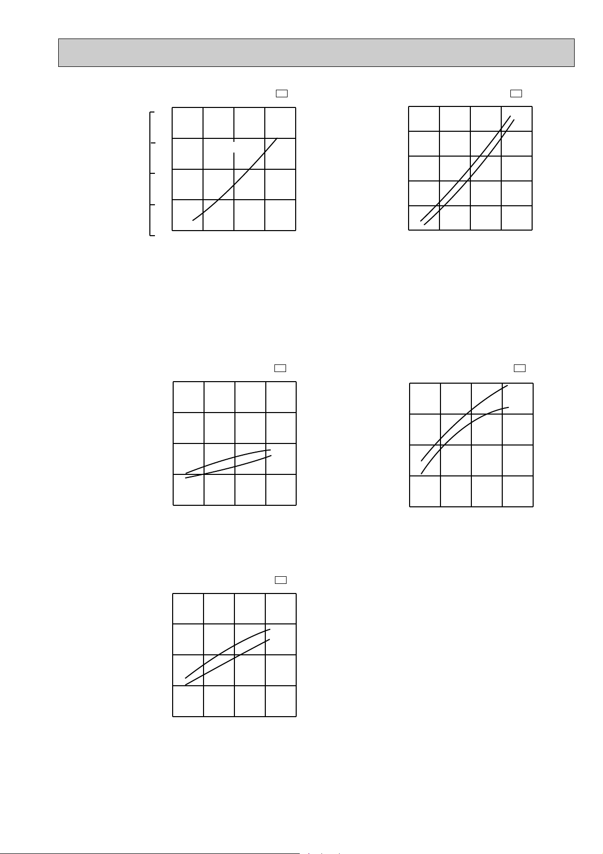
7
PERFORMANCE CURVES
MSH-XV07UV - MSH-XV12UV MSH-XV09UV -
The standard data contained in these specifications apply only to the operation of the air conditioner under normal conditions,
since operating conditions vary according to the areas where these units are installed. The following information has been provided to clarify the operating characteristics of the air conditioner under the conditions indicated by the performance curve.
E1
E1E1
MUH-XV07UV - MUH-XV12UV MUH-XV09UV -
E1
E1E1
(1) GUARANTEED VOLTAGE
198 ~ 264V,50Hz
(2) AIR FLOW
Air flow should be set at MAX.
(3) MAIN READINGS
(1) Indoor intake air wet-bulb temperature : °CWB
(2) Indoor outlet air wet-bulb temperature : °CWB
(3) Outdoor intake air dry-bulb temperature : °CDB
(4) Total input: W
(5) Indoor intake air dry-bulb temperature : °CDB
(6) Outdoor intake air wet-bulb temperature : °CWB
(7) Total input : W
Indoor air wet/dry-bulb temperature difference on the left side of the chart on this page and next page shows the difference between the indoor intake air wet/dry-bulb temperature and the indoor outlet air wet/dry-bulb temperature for your
reference at service.
}
}
Cooling
Heating
How to measure the indoor air wet-bulb/dry-bulb temperature difference
1. Attach at least 2 sets of wet and dry-bulb thermometers to the indoor air intake as shown in the figure, and at least 2 sets
of wet and dry-bulb thermometers to the indoor air outlet. The thermometers must be attached to the position where air
speed is high.
2. Attach at least 2 sets of wet and dry-bulb thermometers to the outdoor air intake.
Cover the thermometers to prevent direct rays of the sun.
3. Check that the air filter is cleaned.
4. Open windows and doors of room.
5. Press the EMERGENCY OPERATION switch once(twice) to start the EMERGENCY COOL(HEAT) MODE.
6. When system stabilizes after more than 15 minutes, measure temperature and take an average temperature.
7. 10 minutes later, measure temperature again and check that the temperature does not change.
INDOOR UNIT
Wet and dry-bulb
thermometers
8.4
9.7
12.3
7.7
8.8
11.2
7.1
8.0
10.2
6.4
7.3
9.2
5.7
6.5
8.2
5.1
5.8
7.3
OUTDOOR UNIT
Wet and dry-bulb
thermometers
MSH-XV12UV - E1
MSH-XV09UV - E1
MSH-XV07UV - E1
13
Page 14
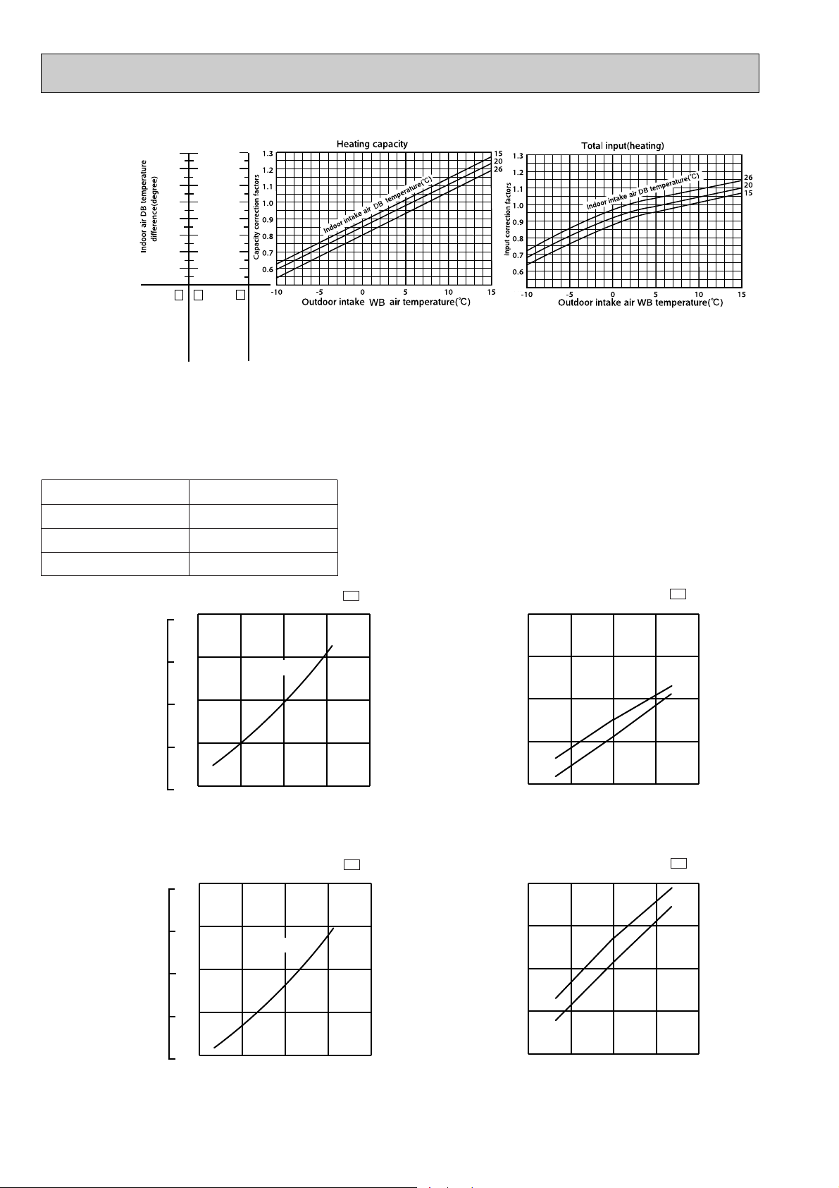
NOTE: The above curves are for the heating operation without any frost.
MSH-XV12UV - E1
MSH-XV09UV - E1
MSH-XV07UV - E1
19.9
18.3
16.8
15.3
13.8
12.2
10.7
9.2
22.8
21.0
19.3
17.5
15.8
14.0
12.3
10.5
26.5
24.4
22.4
20.4
18.3
16.3
14.3
12.2
15 20
50
25
60
30
70(%)
35(:)
0.3
0.4
0.5
0.6
0.7
18 32
220V-240V
7
6
5
4
3
15 20 25 30 35
2.0
2.5
3.0
3.5
4.0
18 32
220V
240V
50 60 70(%)
(:)
15 20
50
25
60
30
70(%)
35(:)
0.3
0.4
0.5
0.6
0.7
18 32
220V-240V
7
6
5
4
3
15 20 25 30 35
2.5
3.0
3.5
4.0
4.5
18 32
220V
240V
50 60 70(%)
(:)
OUTDOOR LOW PRESSURE AND OUTDOOR UNIT CURRENT
COOL operation
① Both indoor and outdoor unit are under the same
temperature/humidity condition.
Dry-bulb temperature
20
25
Relative humidity(%)
50
60
30 70
➁ Air flow should be set at MAX.
③ The unit of pressure has been changed to MPa on the
international system of units(SI unit system).
The conversion factor is : 1(MPa[Gauge]) =10.2(kgf/ff[Gauge])
(kgf/F[Gauge])(MPa[Gauge])
MUH-XV07UV -
Outdoor low pressure
Ambient temperature(˚C) Ambient humidity(%)
(kgf/F[Gauge])(MPa[Gauge])
Outdoor low pressure
Ambient temperature(˚C) Ambient humidity(%)
MUH-XV09UV -
E1
MUH-XV07UV -
Outdoor unit current (A)
Ambient temperature(˚C) Ambient humidity(%)
E1
MUH-XV09UV -
Outdoor unit current (A)
Ambient temperature(˚C) Ambient humidity(%)
E1
E1
14
Page 15
5 10152025
5.5
6.0
6.5
7.0
7.5
7
21
240V
220V
(:)
5 10152025
2.5
3.0
3.5
4.0
4.5
7
21
(:)
240V
220V
(kgf/F[Gauge])(MPa[Gauge])
15 20
50
25
60
30 32
70(%)
35(:)
0.3
0.4
0.5
0.6
0.7
18
220V-240V
7
6
5
4
3
15 20
50
25
603070(%)
35
4.0
4.5
5.0
5.5
6.5
6.0
(:
18
32
240V
220V
5 10152025
3.5
4.0
4.5
5.0
5.5
7
21
(:)
240V
220V
MUH-XV12UV -
E1
MUH-XV12UV -
E1
Outdoor low pressure
Ambient temperature(˚C) Ambient humidity(%) Ambient temperature(˚C) Ambient humidity(%)
HEAT operation
Condition indoor:Dry bulb temperature 20.0°C
Outdoor unit current (A)
Wet bulb temperature 14.5°C
MUH-XV07UV -
E1
Outdoor unit current (A)
Outdoor:Dry bulb temperature 7,15,20°C
Wet bulb temperature 6,12,14.5°C
MUH-XV12UV -
Outdoor unit current (A)
E1
Outdoor unit current (A)
MUH-XV09UV -
Ambient temperature(˚C)
Ambient temperature(˚C)Ambient temperature(˚C)
E1
15
Page 16

PERFORMANCE DATA COOL operation
21
21
22
22
22
23
23
23
24
24
24
24
25
25
25
25
26
26
26
26
26
27
27
27
27
27
28
28
28
28
28
29
29
29
29
29
30
30
30
30
30
31
31
31
31
31
32
32
32
32
32
18
20
18
20
22
18
20
22
18
20
22
24
18
20
22
24
18
20
22
24
26
18
20
22
24
26
18
20
22
24
26
18
20
22
24
26
18
20
22
24
26
18
20
22
24
26
18
20
22
24
26
2.47
2.57
2.47
2.57
2.68
2.47
2.57
2.68
2.47
2.57
2.68
2.81
2.47
2.57
2.68
2.81
2.47
2.57
2.68
2.81
2.90
2.47
2.57
2.68
2.81
2.90
2.47
2.57
2.68
2.81
2.90
2.47
2.57
2.68
2.81
2.90
2.47
2.57
2.68
2.81
2.90
2.47
2.57
2.68
2.81
2.90
2.47
2.57
2.68
2.81
2.90
1.38
1.13
1.48
1.23
0.96
1.58
1.34
1.07
1.68
1.44
1.18
0.90
1.78
1.54
1.29
1.01
1.88
1.65
1.39
1.13
0.81
1.97
1.75
1.50
1.24
0.93
2.07
1.85
1.61
1.35
1.04
2.17
1.96
1.71
1.46
1.16
2.27
2.06
1.82
1.58
1.28
2.37
2.16
1.93
1.69
1.39
2.47
2.26
2.03
1.80
1.51
0.56
0.44
0.60
0.48
0.36
0.64
0.52
0.40
0.68
0.56
0.44
0.32
0.72
0.60
0.48
0.36
0.76
0.64
0.52
0.40
0.28
0.80
0.68
0.56
0.44
0.32
0.84
0.72
0.60
0.48
0.36
0.88
0.76
0.64
0.52
0.40
0.92
0.80
0.68
0.56
0.44
0.96
0.84
0.72
0.60
0.48
1.00
0.88
0.76
0.64
0.52
568
596
568
596
618
568
596
618
568
596
618
646
568
596
618
646
568
596
618
646
682
568
596
618
646
682
568
596
618
646
682
568
596
618
646
682
568
596
618
646
682
568
596
618
646
682
568
596
618
646
682
2.36
2.47
2.36
2.47
2.58
2.36
2.47
2.58
2.36
2.47
2.58
2.71
2.36
2.47
2.58
2.71
2.36
2.47
2.58
2.71
2.81
2.36
2.47
2.58
2.71
2.81
2.36
2.47
2.58
2.71
2.81
2.36
2.47
2.58
2.71
2.81
2.36
2.47
2.58
2.71
2.81
2.36
2.47
2.58
2.71
2.81
2.36
2.47
2.58
2.71
2.81
1.32
1.09
1.42
1.18
0.93
1.51
1.28
1.03
1.61
1.38
1.14
0.87
1.70
1.48
1.24
0.98
1.80
1.58
1.34
1.08
0.79
1.89
1.68
1.45
1.19
0.90
1.98
1.78
1.55
1.30
1.01
2.08
1.88
1.65
1.41
1.13
2.17
1.97
1.76
1.52
1.24
2.27
2.07
1.86
1.63
1.35
2.36
2.17
1.96
1.73
1.46
0.56
0.44
0.60
0.48
0.36
0.64
0.52
0.40
0.68
0.56
0.44
0.32
0.72
0.60
0.48
0.36
0.76
0.64
0.52
0.40
0.28
0.80
0.68
0.56
0.44
0.32
0.84
0.72
0.60
0.48
0.36
0.88
0.76
0.64
0.52
0.40
0.92
0.80
0.68
0.56
0.44
0.96
0.84
0.72
0.60
0.48
1.00
0.88
0.76
0.64
0.52
596
632
596
632
657
596
632
657
596
632
657
682
596
632
657
682
596
632
657
682
717
596
632
657
682
717
596
632
657
682
717
596
632
657
682
717
596
632
657
682
717
596
632
657
682
717
596
632
657
682
717
2.27
2.39
2.27
2.39
2.52
2.27
2.39
2.52
2.27
2.39
2.52
2.65
2.27
2.39
2.52
2.65
2.27
2.39
2.52
2.65
2.77
2.27
2.39
2.52
2.65
2.77
2.27
2.39
2.52
2.65
2.77
2.27
2.39
2.52
2.65
2.77
2.27
2.39
2.52
2.65
2.77
2.27
2.39
2.52
2.65
2.77
2.27
2.39
2.52
2.65
2.77
1.27
1.05
1.36
1.15
0.91
1.45
1.24
1.01
1.54
1.34
1.11
0.85
1.63
1.44
1.21
0.95
1.72
1.53
1.31
1.06
0.78
1.81
1.63
1.41
1.16
0.89
1.91
1.72
1.51
1.27
1.00
2.00
1.82
1.61
1.38
1.11
2.09
1.92
1.71
1.48
1.22
2.18
2.01
1.81
1.59
1.33
2.27
2.11
1.92
1.69
1.44
0.56
0.44
0.60
0.48
0.36
0.64
0.52
0.40
0.68
0.56
0.44
0.32
0.72
0.60
0.48
0.36
0.76
0.64
0.52
0.40
0.28
0.80
0.68
0.56
0.44
0.32
0.84
0.72
0.60
0.48
0.36
0.88
0.76
0.64
0.52
0.40
0.92
0.80
0.68
0.56
0.44
0.96
0.84
0.72
0.60
0.48
1.00
0.88
0.76
0.64
0.52
625
646
625
646
675
625
646
675
625
646
675
703
625
646
675
703
625
646
675
703
738
625
646
675
703
738
625
646
675
703
738
625
646
675
703
738
625
646
675
703
738
625
646
675
703
738
625
646
675
703
738
2.18
2.31
2.18
2.31
2.42
2.18
2.31
2.42
2.18
2.31
2.42
2.56
2.18
2.31
2.42
2.56
2.18
2.31
2.42
2.56
2.69
2.18
2.31
2.42
2.56
2.69
2.18
2.31
2.42
2.56
2.69
2.18
2.31
2.42
2.56
2.69
2.18
2.31
2.42
2.56
2.69
2.18
2.31
2.42
2.56
2.69
2.18
2.31
2.42
2.56
2.69
1.22
1.02
1.31
1.11
0.87
1.40
1.20
0.97
1.49
1.29
1.06
0.82
1.57
1.39
1.16
0.92
1.66
1.48
1.26
1.02
0.75
1.75
1.57
1.35
1.13
0.86
1.83
1.66
1.45
1.23
0.97
1.92
1.76
1.55
1.33
1.08
2.01
1.85
1.64
1.43
1.18
2.10
1.94
1.74
1.54
1.29
2.18
2.03
1.84
1.64
1.40
0.56
0.44
0.60
0.48
0.36
0.64
0.52
0.40
0.68
0.56
0.44
0.32
0.72
0.60
0.48
0.36
0.76
0.64
0.52
0.40
0.28
0.80
0.68
0.56
0.44
0.32
0.84
0.72
0.60
0.48
0.36
0.88
0.76
0.64
0.52
0.40
0.92
0.80
0.68
0.56
0.44
0.96
0.84
0.72
0.60
0.48
1.00
0.88
0.76
0.64
0.52
653
675
653
675
703
653
675
703
653
675
703
738
653
675
703
738
653
675
703
738
760
653
675
703
738
760
653
675
703
738
760
653
675
703
738
760
653
675
703
738
760
653
675
703
738
760
653
675
703
738
760
CAPACITY : 2.1(KW) SHF : 0.74 INPUT : 710(W)
INDOOR
DB(:)
INDOOR
WB(:)
OUTDOOR DB(:)
21 2725
Q SHC SHF INPUT Q SHC SHF INPUT Q SHC SHF INPUT30Q SHC SHF INPUT
MSH-XV07UV - : MUH-XV07UV - (220V)
E1E1
NOTE Q : Total capacity (kW) SHF : Sensible heat factor DB : Dry-bulb temperature
SHC : Sensible heat capacity (kW) INPUT : Total power input (W) WB : Wet-bulb temperature
16
Page 17

PERFORMANCE DATA COOL operation
21
21
22
22
22
23
23
23
24
24
24
24
25
25
25
25
26
26
26
26
26
27
27
27
27
27
28
28
28
28
28
29
29
29
29
29
30
30
30
30
30
31
31
31
31
31
32
32
32
32
32
18
20
18
20
22
18
20
22
18
20
22
24
18
20
22
24
18
20
22
24
26
18
20
22
24
26
18
20
22
24
26
18
20
22
24
26
18
20
22
24
26
18
20
22
24
26
18
20
22
24
26
2.06
2.16
2.06
2.16
2.29
2.06
2.16
2.29
2.06
2.16
2.29
2.42
2.06
2.16
2.29
2.42
2.06
2.16
2.29
2.42
2.54
2.06
2.16
2.29
2.42
2.54
2.06
2.16
2.29
2.42
2.54
2.06
2.16
2.29
2.42
2.54
2.06
2.16
2.29
2.42
2.54
2.06
2.16
2.29
2.42
2.54
2.06
2.16
2.29
2.42
2.54
1.15
0.95
1.23
1.04
0.82
1.32
1.12
0.92
1.40
1.21
1.01
0.77
1.48
1.30
1.10
0.87
1.56
1.38
1.19
0.97
0.71
1.65
1.47
1.28
1.06
0.81
1.73
1.56
1.37
1.16
0.91
1.81
1.64
1.46
1.26
1.02
1.89
1.73
1.56
1.35
1.12
1.98
1.82
1.65
1.45
1.22
2.06
1.90
1.74
1.55
1.32
0.56
0.44
0.60
0.48
0.36
0.64
0.52
0.40
0.68
0.56
0.44
0.32
0.72
0.60
0.48
0.36
0.76
0.64
0.52
0.40
0.28
0.80
0.68
0.56
0.44
0.32
0.84
0.72
0.60
0.48
0.36
0.88
0.76
0.64
0.52
0.40
0.92
0.80
0.68
0.56
0.44
0.96
0.84
0.72
0.60
0.48
1.00
0.88
0.76
0.64
0.52
696
724
696
724
753
696
724
753
696
724
753
781
696
724
753
781
696
724
753
781
809
696
724
753
781
809
696
724
753
781
809
696
724
753
781
809
696
724
753
781
809
696
724
753
781
809
696
724
753
781
809
1.89
2.02
1.89
2.02
2.14
1.89
2.02
2.14
1.89
2.02
2.14
2.27
1.89
2.02
2.14
2.27
1.89
2.02
2.14
2.27
2.39
1.89
2.02
2.14
2.27
2.39
1.89
2.02
2.14
2.27
2.39
1.89
2.02
2.14
2.27
2.39
1.89
2.02
2.14
2.27
2.39
1.89
2.02
2.14
2.27
2.39
1.89
2.02
2.14
2.27
2.39
1.06
0.89
1.13
0.97
0.77
1.21
1.05
0.86
1.29
1.13
0.94
0.73
1.36
1.21
1.03
0.82
1.44
1.29
1.11
0.91
0.67
1.51
1.37
1.20
1.00
0.77
1.59
1.45
1.29
1.09
0.86
1.66
1.53
1.37
1.18
0.96
1.74
1.61
1.46
1.27
1.05
1.81
1.69
1.54
1.36
1.15
1.89
1.77
1.63
1.45
1.24
0.56
0.44
0.60
0.48
0.36
0.64
0.52
0.40
0.68
0.56
0.44
0.32
0.72
0.60
0.48
0.36
0.76
0.64
0.52
0.40
0.28
0.80
0.68
0.56
0.44
0.32
0.84
0.72
0.60
0.48
0.36
0.88
0.76
0.64
0.52
0.40
0.92
0.80
0.68
0.56
0.44
0.96
0.84
0.72
0.60
0.48
1.00
0.88
0.76
0.64
0.52
738
760
738
760
795
738
760
795
738
760
795
817
738
760
795
817
738
760
795
817
845
738
760
795
817
845
738
760
795
817
845
738
760
795
817
845
738
760
795
817
845
738
760
795
817
845
738
760
795
817
845
1.82
1.94
1.82
1.94
2.07
1.82
1.94
2.07
1.82
1.94
2.07
2.21
1.82
1.94
2.07
2.21
1.82
1.94
2.07
2.21
2.32
1.82
1.94
2.07
2.21
2.32
1.82
1.94
2.07
2.21
2.32
1.82
1.94
2.07
2.21
2.32
1.82
1.94
2.07
2.21
2.32
1.82
1.94
2.07
2.21
2.32
1.82
1.94
2.07
2.21
2.32
1.02
0.85
1.09
0.93
0.74
1.16
1.01
0.83
1.24
1.09
0.91
0.71
1.31
1.17
0.99
0.79
1.38
1.24
1.08
0.88
0.65
1.45
1.32
1.16
0.97
0.74
1.53
1.40
1.24
1.06
0.84
1.60
1.48
1.32
1.15
0.93
1.67
1.55
1.41
1.23
1.02
1.74
1.63
1.49
1.32
1.11
1.82
1.71
1.57
1.41
1.21
0.56
0.44
0.60
0.48
0.36
0.64
0.52
0.40
0.68
0.56
0.44
0.32
0.72
0.60
0.48
0.36
0.76
0.64
0.52
0.40
0.28
0.80
0.68
0.56
0.44
0.32
0.84
0.72
0.60
0.48
0.36
0.88
0.76
0.64
0.52
0.40
0.92
0.80
0.68
0.56
0.44
0.96
0.84
0.72
0.60
0.48
1.00
0.88
0.76
0.64
0.52
753
781
753
781
809
753
781
809
753
781
809
834
753
781
809
834
753
781
809
834
863
753
781
809
834
863
753
781
809
834
863
753
781
809
834
863
753
781
809
834
863
753
781
809
834
863
753
781
809
834
863
1.74
1.87
1.74
1.87
2.00
1.74
1.87
2.00
1.74
1.87
2.00
2.14
1.74
1.87
2.00
2.14
1.74
1.87
2.00
2.14
2.25
1.74
1.87
2.00
2.14
2.25
1.74
1.87
2.00
2.14
2.25
1.74
1.87
2.00
2.14
2.25
1.74
1.87
2.00
2.14
2.25
1.74
1.87
2.00
2.14
2.25
1.74
1.87
2.00
2.14
2.25
0.98
0.82
1.05
0.90
0.72
1.12
0.97
0.80
1.19
1.05
0.88
0.69
1.25
1.12
0.96
0.77
1.32
1.20
1.04
0.86
0.63
1.39
1.27
1.12
0.94
0.72
1.46
1.35
1.20
1.03
0.81
1.53
1.42
1.28
1.11
0.90
1.60
1.50
1.36
1.20
0.99
1.67
1.57
1.44
1.29
1.08
1.74
1.64
1.52
1.37
1.17
0.56
0.44
0.60
0.48
0.36
0.64
0.52
0.40
0.68
0.56
0.44
0.32
0.72
0.60
0.48
0.36
0.76
0.64
0.52
0.40
0.28
0.80
0.68
0.56
0.44
0.32
0.84
0.72
0.60
0.48
0.36
0.88
0.76
0.64
0.52
0.40
0.92
0.80
0.68
0.56
0.44
0.96
0.84
0.72
0.60
0.48
1.00
0.88
0.76
0.64
0.52
767
802
767
802
824
767
802
824
767
802
824
852
767
802
824
852
767
802
824
852
880
767
802
824
852
880
767
802
824
852
880
767
802
824
852
880
767
802
824
852
880
767
802
824
852
880
767
802
824
852
880
CAPACITY : 2.1(KW) SHF : 0.74 INPUT : 710(W)
INDOOR
DB(:)
INDOOR
WB(:)
OUTDOOR DB(:)
35 4340
Q SHC SHF INPUT Q SHC SHF INPUT Q SHC SHF INPUT46Q SHC SHF INPUT
MSH-XV07UV - : MUH-XV07UV - (220V)
E1E1
NOTE Q : Total capacity (kW) SHF : Sensible heat factor DB : Dry-bulb temperature
SHC : Sensible heat capacity (kW) INPUT : Total power input (W) WB : Wet-bulb temperature
17
Page 18

PERFORMANCE DATA COOL operation
21
21
22
22
22
23
23
23
24
24
24
24
25
25
25
25
26
26
26
26
26
27
27
27
27
27
28
28
28
28
28
29
29
29
29
29
30
30
30
30
30
31
31
31
31
31
32
32
32
32
32
18
20
18
20
22
18
20
22
18
20
22
24
18
20
22
24
18
20
22
24
26
18
20
22
24
26
18
20
22
24
26
18
20
22
24
26
18
20
22
24
26
18
20
22
24
26
18
20
22
24
26
2.47
2.57
2.47
2.57
2.68
2.47
2.57
2.68
2.47
2.57
2.68
2.81
2.47
2.57
2.68
2.81
2.47
2.57
2.68
2.81
2.90
2.47
2.57
2.68
2.81
2.90
2.47
2.57
2.68
2.81
2.90
2.47
2.57
2.68
2.81
2.90
2.47
2.57
2.68
2.81
2.90
2.47
2.57
2.68
2.81
2.90
2.47
2.57
2.68
2.81
2.90
1.38
1.13
1.48
1.23
0.96
1.58
1.34
1.07
1.68
1.44
1.18
0.90
1.78
1.54
1.29
1.01
1.88
1.65
1.39
1.13
0.81
1.97
1.75
1.50
1.24
0.93
2.07
1.85
1.61
1.35
1.04
2.17
1.96
1.71
1.46
1.16
2.27
2.06
1.82
1.58
1.28
2.37
2.16
1.93
1.69
1.39
2.47
2.26
2.03
1.80
1.51
0.56
0.44
0.60
0.48
0.36
0.64
0.52
0.40
0.68
0.56
0.44
0.32
0.72
0.60
0.48
0.36
0.76
0.64
0.52
0.40
0.28
0.80
0.68
0.56
0.44
0.32
0.84
0.72
0.60
0.48
0.36
0.88
0.76
0.64
0.52
0.40
0.92
0.80
0.68
0.56
0.44
0.96
0.84
0.72
0.60
0.48
1.00
0.88
0.76
0.64
0.52
592
622
592
622
644
592
622
644
592
622
644
673
592
622
644
673
592
622
644
673
710
592
622
644
673
710
592
622
644
673
710
592
622
644
673
710
592
622
644
673
710
592
622
644
673
710
592
622
644
673
710
2.36
2.47
2.36
2.47
2.58
2.36
2.47
2.58
2.36
2.47
2.58
2.71
2.36
2.47
2.58
2.71
2.36
2.47
2.58
2.71
2.81
2.36
2.47
2.58
2.71
2.81
2.36
2.47
2.58
2.71
2.81
2.36
2.47
2.58
2.71
2.81
2.36
2.47
2.58
2.71
2.81
2.36
2.47
2.58
2.71
2.81
2.36
2.47
2.58
2.71
2.81
1.32
1.09
1.42
1.18
0.93
1.51
1.28
1.03
1.61
1.38
1.14
0.87
1.70
1.48
1.24
0.98
1.80
1.58
1.34
1.08
0.79
1.89
1.68
1.45
1.19
0.90
1.98
1.78
1.55
1.30
1.01
2.08
1.88
1.65
1.41
1.13
2.17
1.97
1.76
1.52
1.24
2.27
2.07
1.86
1.63
1.35
2.36
2.17
1.96
1.73
1.46
0.56
0.44
0.60
0.48
0.36
0.64
0.52
0.40
0.68
0.56
0.44
0.32
0.72
0.60
0.48
0.36
0.76
0.64
0.52
0.40
0.28
0.80
0.68
0.56
0.44
0.32
0.84
0.72
0.60
0.48
0.36
0.88
0.76
0.64
0.52
0.40
0.92
0.80
0.68
0.56
0.44
0.96
0.84
0.72
0.60
0.48
1.00
0.88
0.76
0.64
0.52
622
659
622
659
685
622
659
685
622
659
685
710
622
659
685
710
622
659
685
710
747
622
659
685
710
747
622
659
685
710
747
622
659
685
710
747
622
659
685
710
747
622
659
685
710
747
622
659
685
710
747
2.27
2.39
2.27
2.39
2.52
2.27
2.39
2.52
2.27
2.39
2.52
2.65
2.27
2.39
2.52
2.65
2.27
2.39
2.52
2.65
2.77
2.27
2.39
2.52
2.65
2.77
2.27
2.39
2.52
2.65
2.77
2.27
2.39
2.52
2.65
2.77
2.27
2.39
2.52
2.65
2.77
2.27
2.39
2.52
2.65
2.77
2.27
2.39
2.52
2.65
2.77
1.27
1.05
1.36
1.15
0.91
1.45
1.24
1.01
1.54
1.34
1.11
0.85
1.63
1.44
1.21
0.95
1.72
1.53
1.31
1.06
0.78
1.81
1.63
1.41
1.16
0.89
1.91
1.72
1.51
1.27
1.00
2.00
1.82
1.61
1.38
1.11
2.09
1.92
1.71
1.48
1.22
2.18
2.01
1.81
1.59
1.33
2.27
2.11
1.92
1.69
1.44
0.56
0.44
0.60
0.48
0.36
0.64
0.52
0.40
0.68
0.56
0.44
0.32
0.72
0.60
0.48
0.36
0.76
0.64
0.52
0.40
0.28
0.80
0.68
0.56
0.44
0.32
0.84
0.72
0.60
0.48
0.36
0.88
0.76
0.64
0.52
0.40
0.92
0.80
0.68
0.56
0.44
0.96
0.84
0.72
0.60
0.48
1.00
0.88
0.76
0.64
0.52
651
673
651
673
703
651
673
703
651
673
703
733
651
673
703
733
651
673
703
733
770
651
673
703
733
770
651
673
703
733
770
651
673
703
733
770
651
673
703
733
770
651
673
703
733
770
651
673
703
733
770
2.18
2.31
2.18
2.31
2.42
2.18
2.31
2.42
2.18
2.31
2.42
2.56
2.18
2.31
2.42
2.56
2.18
2.31
2.42
2.56
2.69
2.18
2.31
2.42
2.56
2.69
2.18
2.31
2.42
2.56
2.69
2.18
2.31
2.42
2.56
2.69
2.18
2.31
2.42
2.56
2.69
2.18
2.31
2.42
2.56
2.69
2.18
2.31
2.42
2.56
2.69
1.22
1.02
1.31
1.11
0.87
1.40
1.20
0.97
1.49
1.29
1.06
0.82
1.57
1.39
1.16
0.92
1.66
1.48
1.26
1.02
0.75
1.75
1.57
1.35
1.13
0.86
1.83
1.66
1.45
1.23
0.97
1.92
1.76
1.55
1.33
1.08
2.01
1.85
1.64
1.43
1.18
2.10
1.94
1.74
1.54
1.29
2.18
2.03
1.84
1.64
1.40
0.56
0.44
0.60
0.48
0.36
0.64
0.52
0.40
0.68
0.56
0.44
0.32
0.72
0.60
0.48
0.36
0.76
0.64
0.52
0.40
0.28
0.80
0.68
0.56
0.44
0.32
0.84
0.72
0.60
0.48
0.36
0.88
0.76
0.64
0.52
0.40
0.92
0.80
0.68
0.56
0.44
0.96
0.84
0.72
0.60
0.48
1.00
0.88
0.76
0.64
0.52
681
703
681
703
733
681
703
733
681
703
733
770
681
703
733
770
681
703
733
770
792
681
703
733
770
792
681
703
733
770
792
681
703
733
770
792
681
703
733
770
792
681
703
733
770
792
681
703
733
770
792
CAPACITY : 2.1(KW) SHF : 0.74 INPUT : 740(W)
INDOOR
DB(:)
INDOOR
WB(:)
OUTDOOR DB(:)
21 2725
Q SHC SHF INPUT Q SHC SHF INPUT Q SHC SHF INPUT30Q SHC SHF INPUT
MSH-XV07UV - : MUH-XV07UV - (240V)
E1E1
NOTE Q : Total capacity (kW) SHF : Sensible heat factor DB : Dry-bulb temperature
SHC : Sensible heat capacity (kW) INPUT : Total power input (W) WB : Wet-bulb temperature
18
Page 19

PERFORMANCE DATA COOL operation
21
21
22
22
22
23
23
23
24
24
24
24
25
25
25
25
26
26
26
26
26
27
27
27
27
27
28
28
28
28
28
29
29
29
29
29
30
30
30
30
30
31
31
31
31
31
32
32
32
32
32
18
20
18
20
22
18
20
22
18
20
22
24
18
20
22
24
18
20
22
24
26
18
20
22
24
26
18
20
22
24
26
18
20
22
24
26
18
20
22
24
26
18
20
22
24
26
18
20
22
24
26
2.06
2.16
2.06
2.16
2.29
2.06
2.16
2.29
2.06
2.16
2.29
2.42
2.06
2.16
2.29
2.42
2.06
2.16
2.29
2.42
2.54
2.06
2.16
2.29
2.42
2.54
2.06
2.16
2.29
2.42
2.54
2.06
2.16
2.29
2.42
2.54
2.06
2.16
2.29
2.42
2.54
2.06
2.16
2.29
2.42
2.54
2.06
2.16
2.29
2.42
2.54
1.15
0.95
1.23
1.04
0.82
1.32
1.12
0.92
1.40
1.21
1.01
0.77
1.48
1.30
1.10
0.87
1.56
1.38
1.19
0.97
0.71
1.65
1.47
1.28
1.06
0.81
1.73
1.56
1.37
1.16
0.91
1.81
1.64
1.46
1.26
1.02
1.89
1.73
1.56
1.35
1.12
1.98
1.82
1.65
1.45
1.22
2.06
1.90
1.74
1.55
1.32
0.56
0.44
0.60
0.48
0.36
0.64
0.52
0.40
0.68
0.56
0.44
0.32
0.72
0.60
0.48
0.36
0.76
0.64
0.52
0.40
0.28
0.80
0.68
0.56
0.44
0.32
0.84
0.72
0.60
0.48
0.36
0.88
0.76
0.64
0.52
0.40
0.92
0.80
0.68
0.56
0.44
0.96
0.84
0.72
0.60
0.48
1.00
0.88
0.76
0.64
0.52
725
755
725
755
784
725
755
784
725
755
784
814
725
755
784
814
725
755
784
814
844
725
755
784
814
844
725
755
784
814
844
725
755
784
814
844
725
755
784
814
844
725
755
784
814
844
725
755
784
814
844
1.89
2.02
1.89
2.02
2.14
1.89
2.02
2.14
1.89
2.02
2.14
2.27
1.89
2.02
2.14
2.27
1.89
2.02
2.14
2.27
2.39
1.89
2.02
2.14
2.27
2.39
1.89
2.02
2.14
2.27
2.39
1.89
2.02
2.14
2.27
2.39
1.89
2.02
2.14
2.27
2.39
1.89
2.02
2.14
2.27
2.39
1.89
2.02
2.14
2.27
2.39
1.06
0.89
1.13
0.97
0.77
1.21
1.05
0.86
1.29
1.13
0.94
0.73
1.36
1.21
1.03
0.82
1.44
1.29
1.11
0.91
0.67
1.51
1.37
1.20
1.00
0.77
1.59
1.45
1.29
1.09
0.86
1.66
1.53
1.37
1.18
0.96
1.74
1.61
1.46
1.27
1.05
1.81
1.69
1.54
1.36
1.15
1.89
1.77
1.63
1.45
1.24
0.56
0.44
0.60
0.48
0.36
0.64
0.52
0.40
0.68
0.56
0.44
0.32
0.72
0.60
0.48
0.36
0.76
0.64
0.52
0.40
0.28
0.80
0.68
0.56
0.44
0.32
0.84
0.72
0.60
0.48
0.36
0.88
0.76
0.64
0.52
0.40
0.92
0.80
0.68
0.56
0.44
0.96
0.84
0.72
0.60
0.48
1.00
0.88
0.76
0.64
0.52
770
792
770
792
829
770
792
829
770
792
829
851
770
792
829
851
770
792
829
851
881
770
792
829
851
881
770
792
829
851
881
770
792
829
851
881
770
792
829
851
881
770
792
829
851
881
770
792
829
851
881
1.82
1.94
1.82
1.94
2.07
1.82
1.94
2.07
1.82
1.94
2.07
2.21
1.82
1.94
2.07
2.21
1.82
1.94
2.07
2.21
2.32
1.82
1.94
2.07
2.21
2.32
1.82
1.94
2.07
2.21
2.32
1.82
1.94
2.07
2.21
2.32
1.82
1.94
2.07
2.21
2.32
1.82
1.94
2.07
2.21
2.32
1.82
1.94
2.07
2.21
2.32
1.02
0.85
1.09
0.93
0.74
1.16
1.01
0.83
1.24
1.09
0.91
0.71
1.31
1.17
0.99
0.79
1.38
1.24
1.08
0.88
0.65
1.45
1.32
1.16
0.97
0.74
1.53
1.40
1.24
1.06
0.84
1.60
1.48
1.32
1.15
0.93
1.67
1.55
1.41
1.23
1.02
1.74
1.63
1.49
1.32
1.11
1.82
1.71
1.57
1.41
1.21
0.56
0.44
0.60
0.48
0.36
0.64
0.52
0.40
0.68
0.56
0.44
0.32
0.72
0.60
0.48
0.36
0.76
0.64
0.52
0.40
0.28
0.80
0.68
0.56
0.44
0.32
0.84
0.72
0.60
0.48
0.36
0.88
0.76
0.64
0.52
0.40
0.92
0.80
0.68
0.56
0.44
0.96
0.84
0.72
0.60
0.48
1.00
0.88
0.76
0.64
0.52
784
814
784
814
844
784
814
844
784
814
844
870
784
814
844
870
784
814
844
870
899
784
814
844
870
899
784
814
844
870
899
784
814
844
870
899
784
814
844
870
899
784
814
844
870
899
784
814
844
870
899
1.74
1.87
1.74
1.87
2.00
1.74
1.87
2.00
1.74
1.87
2.00
2.14
1.74
1.87
2.00
2.14
1.74
1.87
2.00
2.14
2.25
1.74
1.87
2.00
2.14
2.25
1.74
1.87
2.00
2.14
2.25
1.74
1.87
2.00
2.14
2.25
1.74
1.87
2.00
2.14
2.25
1.74
1.87
2.00
2.14
2.25
1.74
1.87
2.00
2.14
2.25
0.98
0.82
1.05
0.90
0.72
1.12
0.97
0.80
1.19
1.05
0.88
0.69
1.25
1.12
0.96
0.77
1.32
1.20
1.04
0.86
0.63
1.39
1.27
1.12
0.94
0.72
1.46
1.35
1.20
1.03
0.81
1.53
1.42
1.28
1.11
0.90
1.60
1.50
1.36
1.20
0.99
1.67
1.57
1.44
1.29
1.08
1.74
1.64
1.52
1.37
1.17
0.56
0.44
0.60
0.48
0.36
0.64
0.52
0.40
0.68
0.56
0.44
0.32
0.72
0.60
0.48
0.36
0.76
0.64
0.52
0.40
0.28
0.80
0.68
0.56
0.44
0.32
0.84
0.72
0.60
0.48
0.36
0.88
0.76
0.64
0.52
0.40
0.92
0.80
0.68
0.56
0.44
0.96
0.84
0.72
0.60
0.48
1.00
0.88
0.76
0.64
0.52
799
836
799
836
858
799
836
858
799
836
858
888
799
836
858
888
799
836
858
888
918
799
836
858
888
918
799
836
858
888
918
799
836
858
888
918
799
836
858
888
918
799
836
858
888
918
799
836
858
888
918
CAPACITY : 2.1(KW) SHF : 0.74 INPUT : 740(W)
INDOOR
DB(:)
INDOOR
WB(:)
OUTDOOR DB(:)
35 4340
Q SHC SHF INPUT Q SHC SHF INPUT Q SHC SHF INPUT46Q SHC SHF INPUT
MSH-XV07UV - : MUH-XV07UV - (240V)
E1E1
NOTE Q : Total capacity (kW) SHF : Sensible heat factor DB : Dry-bulb temperature
SHC : Sensible heat capacity (kW) INPUT : Total power input (W) WB : Wet-bulb temperature
19
Page 20

PERFORMANCE DATA COOL operation
21
21
22
22
22
23
23
23
24
24
24
24
25
25
25
25
26
26
26
26
26
27
27
27
27
27
28
28
28
28
28
29
29
29
29
29
30
30
30
30
30
31
31
31
31
31
32
32
32
32
32
18
20
18
20
22
18
20
22
18
20
22
24
18
20
22
24
18
20
22
24
26
18
20
22
24
26
18
20
22
24
26
18
20
22
24
26
18
20
22
24
26
18
20
22
24
26
18
20
22
24
26
2.94
3.06
2.94
3.06
3.19
2.94
3.06
3.19
2.94
3.06
3.19
3.35
2.94
3.06
3.19
3.35
2.94
3.06
3.19
3.35
3.45
2.94
3.06
3.19
3.35
3.45
2.94
3.06
3.19
3.35
3.45
2.94
3.06
3.19
3.35
3.45
2.94
3.06
3.19
3.35
3.45
2.94
3.06
3.19
3.35
3.45
2.94
3.06
3.19
3.35
3.45
1.53
1.23
1.65
1.35
1.02
1.76
1.47
1.15
1.88
1.59
1.28
0.94
2.00
1.72
1.40
1.07
2.12
1.84
1.53
1.21
0.83
2.23
1.96
1.66
1.34
0.97
2.35
2.08
1.76
1.47
1.10
2.47
2.21
1.91
1.61
1.24
2.59
2.33
2.04
1.74
1.38
2.70
2.45
2.17
1.88
1.52
2.82
2.57
2.30
2.01
1.66
0.52
0.40
0.56
0.44
0.32
0.60
0.48
0.36
0.64
0.52
0.40
0.28
0.68
0.56
0.44
0.32
0.72
0.60
0.48
0.36
0.24
0.76
0.64
0.52
0.40
0.28
0.80
0.68
0.56
0.44
0.32
0.84
0.72
0.60
0.48
0.36
0.88
0.76
0.64
0.52
0.40
0.92
0.80
0.68
0.56
0.44
0.96
0.84
0.72
0.60
0.48
752
790
752
790
818
752
790
818
752
790
818
855
752
790
818
855
752
790
818
855
902
752
790
818
855
902
752
790
818
855
902
752
790
818
855
902
752
790
818
855
902
752
790
818
855
902
752
790
818
855
902
2.81
2.94
2.81
2.94
3.08
2.81
2.94
3.08
2.81
2.94
3.08
3.23
2.81
2.94
3.08
3.23
2.81
2.94
3.08
3.23
3.35
2.81
2.94
3.08
3.23
3.35
2.81
2.94
3.08
3.23
3.35
2.81
2.94
3.08
3.23
3.35
2.81
2.94
3.08
3.23
3.35
2.81
2.94
3.08
3.23
3.35
2.81
2.94
3.08
3.23
3.35
1.46
1.18
1.58
1.29
0.98
1.69
1.41
1.11
1.80
1.53
1.23
0.90
1.91
1.65
1.35
1.03
2.03
1.76
1.48
1.16
0.80
2.14
1.88
1.60
1.29
0.94
2.25
2.00
1.72
1.42
1.07
2.36
2.12
1.85
1.55
1.21
2.48
2.23
1.97
1.68
1.34
2.59
2.35
2.09
1.81
1.47
2.70
2.47
2.21
1.94
1.61
0.52
0.40
0.56
0.44
0.32
0.60
0.48
0.36
0.64
0.52
0.40
0.28
0.68
0.56
0.44
0.32
0.72
0.60
0.48
0.36
0.24
0.76
0.64
0.52
0.40
0.28
0.80
0.68
0.56
0.44
0.32
0.84
0.72
0.60
0.48
0.36
0.88
0.76
0.64
0.52
0.40
0.92
0.80
0.68
0.56
0.44
0.96
0.84
0.72
0.60
0.48
790
837
790
837
870
790
837
870
790
837
870
902
790
837
870
902
790
837
870
902
949
790
837
870
902
949
790
837
870
902
949
790
837
870
902
949
790
837
870
902
949
790
837
870
902
949
790
837
870
902
949
2.70
2.85
2.70
2.85
3.00
2.70
2.85
3.00
2.70
2.85
3.00
3.15
2.70
2.85
3.00
3.15
2.70
2.85
3.00
3.15
3.30
2.70
2.85
3.00
3.15
3.30
2.70
2.85
3.00
3.15
3.30
2.70
2.85
3.00
3.15
3.30
2.70
2.85
3.00
3.15
3.30
2.70
2.85
3.00
3.15
3.30
2.70
2.85
3.00
3.15
3.30
1.40
1.14
1.51
1.25
0.96
1.62
1.37
1.08
1.73
1.48
1.20
0.88
1.84
1.60
1.32
1.01
1.94
1.71
1.44
1.13
0.79
2.05
1.82
1.56
1.26
0.92
2.16
1.94
1.68
1.39
1.06
2.27
2.05
1.80
1.51
1.19
2.38
2.17
1.92
1.64
1.32
2.48
2.28
2.04
1.76
1.45
2.59
2.39
2.16
1.89
1.58
0.52
0.40
0.56
0.44
0.32
0.60
0.48
0.36
0.64
0.52
0.40
0.28
0.68
0.56
0.44
0.32
0.72
0.60
0.48
0.36
0.24
0.76
0.64
0.52
0.40
0.28
0.80
0.68
0.56
0.44
0.32
0.84
0.72
0.60
0.48
0.36
0.88
0.76
0.64
0.52
0.40
0.92
0.80
0.68
0.56
0.44
0.96
0.84
0.72
0.60
0.48
827
855
827
855
893
827
855
893
827
855
893
931
827
855
893
931
827
855
893
931
978
827
855
893
931
978
827
855
893
931
978
827
855
893
931
978
827
855
893
931
978
827
855
893
931
978
827
855
893
931
978
2.60
2.75
2.60
2.75
2.88
2.60
2.75
2.88
2.60
2.75
2.88
3.05
2.60
2.75
2.88
3.05
2.60
2.75
2.88
3.05
3.20
2.60
2.75
2.88
3.05
3.20
2.60
2.75
2.88
3.05
3.20
2.60
2.75
2.88
3.05
3.20
2.60
2.75
2.88
3.05
3.20
2.60
2.75
2.88
3.05
3.20
2.60
2.75
2.88
3.05
3.20
1.35
1.10
1.46
1.21
0.92
1.56
1.32
1.04
1.66
1.43
1.15
0.85
1.77
1.54
1.27
0.98
1.87
1.65
1.38
1.10
0.77
1.98
1.76
1.50
1.22
0.90
2.08
1.87
1.61
1.34
1.02
2.18
1.98
1.73
1.46
1.15
2.29
2.09
1.84
1.59
1.28
2.39
2.20
1.96
1.71
1.41
2.50
2.31
2.07
1.83
1.54
0.52
0.40
0.56
0.44
0.32
0.60
0.48
0.36
0.64
0.52
0.40
0.28
0.68
0.56
0.44
0.32
0.72
0.60
0.48
0.36
0.24
0.76
0.64
0.52
0.40
0.28
0.80
0.68
0.56
0.44
0.32
0.84
0.72
0.60
0.48
0.36
0.88
0.76
0.64
0.52
0.40
0.92
0.80
0.68
0.56
0.44
0.96
0.84
0.72
0.60
0.48
865
893
865
893
931
865
893
931
865
893
931
978
865
893
931
978
865
893
931
978
1006
865
893
931
978
1006
865
893
931
978
1006
865
893
931
978
1006
865
893
931
978
1006
865
893
931
978
1006
865
893
931
978
1006
CAPACITY : 2.5(KW) SHF : 0.7 INPUT : 940(W)
INDOOR
DB(:)
INDOOR
WB(:)
OUTDOOR DB(:)
21 2725
Q SHC SHF INPUT Q SHC SHF INPUT Q SHC SHF INPUT30Q SHC SHF INPUT
MSH-XV09UV - : MUH-XV09UV - (220V)
E1E1
NOTE Q : Total capacity (kW) SHF : Sensible heat factor DB : Dry-bulb temperature
SHC : Sensible heat capacity (kW) INPUT : Total power input (W) WB : Wet-bulb temperature
20
Page 21

PERFORMANCE DATA COOL operation
21
21
22
22
22
23
23
23
24
24
24
24
25
25
25
25
26
26
26
26
26
27
27
27
27
27
28
28
28
28
28
29
29
29
29
29
30
30
30
30
30
31
31
31
31
31
32
32
32
32
32
18
20
18
20
22
18
20
22
18
20
22
24
18
20
22
24
18
20
22
24
26
18
20
22
24
26
18
20
22
24
26
18
20
22
24
26
18
20
22
24
26
18
20
22
24
26
18
20
22
24
26
2.45
2.58
2.45
2.58
2.73
2.45
2.58
2.73
2.45
2.58
2.73
2.88
2.45
2.58
2.73
2.88
2.45
2.58
2.73
2.88
3.03
2.45
2.58
2.73
2.88
3.03
2.45
2.58
2.73
2.88
3.03
2.45
2.58
2.73
2.88
3.03
2.45
2.58
2.73
2.88
3.03
2.45
2.58
2.73
2.88
3.03
2.45
2.58
2.73
2.88
3.03
1.27
1.03
1.37
1.13
0.87
1.47
1.24
0.98
1.57
1.34
1.09
0.81
1.67
1.44
1.20
0.92
1.76
1.55
1.31
1.04
0.73
1.86
1.65
1.42
1.15
0.85
1.96
1.75
1.53
1.27
0.97
2.06
1.85
1.64
1.38
1.09
2.16
1.96
1.74
1.50
1.21
2.25
2.06
1.85
1.61
1.33
2.35
2.16
1.96
1.73
1.45
0.52
0.40
0.56
0.44
0.32
0.60
0.48
0.36
0.64
0.52
0.40
0.28
0.68
0.56
0.44
0.32
0.72
0.60
0.48
0.36
0.24
0.76
0.64
0.52
0.40
0.28
0.80
0.68
0.56
0.44
0.32
0.84
0.72
0.60
0.48
0.36
0.88
0.76
0.64
0.52
0.40
0.92
0.80
0.68
0.56
0.44
0.96
0.84
0.72
0.60
0.48
921
959
921
959
996
921
959
996
921
959
996
1034
921
959
996
1034
921
959
996
1034
1072
921
959
996
1034
1072
921
959
996
1034
1072
921
959
996
1034
1072
921
959
996
1034
1072
921
959
996
1034
1072
921
959
996
1034
1072
2.25
2.40
2.25
2.40
2.55
2.25
2.40
2.55
2.25
2.40
2.55
2.70
2.25
2.40
2.55
2.70
2.25
2.40
2.55
2.70
2.85
2.25
2.40
2.55
2.70
2.85
2.25
2.40
2.55
2.70
2.85
2.25
2.40
2.55
2.70
2.85
2.25
2.40
2.55
2.70
2.85
2.25
2.40
2.55
2.70
2.85
2.25
2.40
2.55
2.70
2.85
1.17
0.96
1.26
1.06
0.82
1.35
1.15
0.92
1.44
1.25
1.02
0.76
1.53
1.34
1.12
0.86
1.62
1.44
1.22
0.97
0.68
1.71
1.54
1.33
1.08
0.80
1.80
1.63
1.43
1.19
0.91
1.89
1.73
1.53
1.30
1.03
1.98
1.82
1.63
1.40
1.14
2.07
1.92
1.73
1.51
1.25
2.16
2.02
1.84
1.62
1.37
0.52
0.40
0.56
0.44
0.32
0.60
0.48
0.36
0.64
0.52
0.40
0.28
0.68
0.56
0.44
0.32
0.72
0.60
0.48
0.36
0.24
0.76
0.64
0.52
0.40
0.28
0.80
0.68
0.56
0.44
0.32
0.84
0.72
0.60
0.48
0.36
0.88
0.76
0.64
0.52
0.40
0.92
0.80
0.68
0.56
0.44
0.96
0.84
0.72
0.60
0.48
978
1006
978
1006
1053
978
1006
1053
978
1006
1053
1081
978
1006
1053
1081
978
1006
1053
1081
1119
978
1006
1053
1081
1119
978
1006
1053
1081
1119
978
1006
1053
1081
1119
978
1006
1053
1081
1119
978
1006
1053
1081
1119
978
1006
1053
1081
1119
2.16
2.31
2.16
2.31
2.46
2.16
2.31
2.46
2.16
2.31
2.46
2.63
2.16
2.31
2.46
2.63
2.16
2.31
2.46
2.63
2.76
2.16
2.31
2.46
2.63
2.76
2.16
2.31
2.46
2.63
2.76
2.16
2.31
2.46
2.63
2.76
2.16
2.31
2.46
2.63
2.76
2.16
2.31
2.46
2.63
2.76
2.16
2.31
2.46
2.63
2.76
1.12
0.93
1.21
1.02
0.79
1.30
1.11
0.89
1.38
1.20
0.99
0.74
1.47
1.30
1.08
0.84
1.56
1.39
1.18
0.95
0.66
1.64
1.48
1.28
1.05
0.77
1.73
1.57
1.38
1.16
0.88
1.82
1.67
1.48
1.26
0.99
1.90
1.76
1.58
1.37
1.11
1.99
1.85
1.67
1.47
1.22
2.08
1.94
1.77
1.58
1.33
0.52
0.40
0.56
0.44
0.32
0.60
0.48
0.36
0.64
0.52
0.40
0.28
0.68
0.56
0.44
0.32
0.72
0.60
0.48
0.36
0.24
0.76
0.64
0.52
0.40
0.28
0.80
0.68
0.56
0.44
0.32
0.84
0.72
0.60
0.48
0.36
0.88
0.76
0.64
0.52
0.40
0.92
0.80
0.68
0.56
0.44
0.96
0.84
0.72
0.60
0.48
996
1034
996
1034
1072
996
1034
1072
996
1034
1072
1105
996
1034
1072
1105
996
1034
1072
1105
1142
996
1034
1072
1105
1142
996
1034
1072
1105
1142
996
1034
1072
1105
1142
996
1034
1072
1105
1142
996
1034
1072
1105
1142
996
1034
1072
1105
1142
2.08
2.23
2.08
2.23
2.38
2.08
2.23
2.38
2.08
2.23
2.38
2.55
2.08
2.23
2.38
2.55
2.08
2.23
2.38
2.55
2.68
2.08
2.23
2.38
2.55
2.68
2.08
2.23
2.38
2.55
2.68
2.08
2.23
2.38
2.55
2.68
2.08
2.23
2.38
2.55
2.68
2.08
2.23
2.38
2.55
2.68
2.08
2.23
2.38
2.55
2.68
1.08
0.89
1.16
0.98
0.76
1.25
1.07
0.86
1.33
1.16
0.95
0.71
1.41
1.25
1.05
0.82
1.49
1.34
1.14
0.92
0.64
1.58
1.42
1.24
1.02
0.75
1.66
1.51
1.33
1.12
0.86
1.74
1.60
1.43
1.22
0.96
1.83
1.69
1.52
1.33
1.07
1.91
1.78
1.62
1.43
1.18
1.99
1.87
1.71
1.53
1.28
0.52
0.40
0.56
0.44
0.32
0.60
0.48
0.36
0.64
0.52
0.40
0.28
0.68
0.56
0.44
0.32
0.72
0.60
0.48
0.36
0.24
0.76
0.64
0.52
0.40
0.28
0.80
0.68
0.56
0.44
0.32
0.84
0.72
0.60
0.48
0.36
0.88
0.76
0.64
0.52
0.40
0.92
0.80
0.68
0.56
0.44
0.96
0.84
0.72
0.60
0.48
1015
1062
1015
1062
1090
1015
1062
1090
1015
1062
1090
1128
1015
1062
1090
1128
1015
1062
1090
1128
1166
1015
1062
1090
1128
1166
1015
1062
1090
1128
1166
1015
1062
1090
1128
1166
1015
1062
1090
1128
1166
1015
1062
1090
1128
1166
1015
1062
1090
1128
1166
CAPACITY : 2.5(KW) SHF : 0.7 INPUT : 940(W)
INDOOR
DB(:)
INDOOR
WB(:)
OUTDOOR DB(:)
35 4340
Q SHC SHF INPUT Q SHC SHF INPUT Q SHC SHF INPUT46Q SHC SHF INPUT
MSH-XV09UV - : MUH-XV09UV - (220V)
E1E1
NOTE Q : Total capacity (kW) SHF : Sensible heat factor DB : Dry-bulb temperature
SHC : Sensible heat capacity (kW) INPUT : Total power input (W) WB : Wet-bulb temperature
21
Page 22

PERFORMANCE DATA COOL operation
21
21
22
22
22
23
23
23
24
24
24
24
25
25
25
25
26
26
26
26
26
27
27
27
27
27
28
28
28
28
28
29
29
29
29
29
30
30
30
30
30
31
31
31
31
31
32
32
32
32
32
18
20
18
20
22
18
20
22
18
20
22
24
18
20
22
24
18
20
22
24
26
18
20
22
24
26
18
20
22
24
26
18
20
22
24
26
18
20
22
24
26
18
20
22
24
26
18
20
22
24
26
2.94
3.06
2.94
3.06
3.19
2.94
3.06
3.19
2.94
3.06
3.19
3.35
2.94
3.06
3.19
3.35
2.94
3.06
3.19
3.35
3.45
2.94
3.06
3.19
3.35
3.45
2.94
3.06
3.19
3.35
3.45
2.94
3.06
3.19
3.35
3.45
2.94
3.06
3.19
3.35
3.45
2.94
3.06
3.19
3.35
3.45
2.94
3.06
3.19
3.35
3.45
1.53
1.23
1.65
1.35
1.02
1.76
1.47
1.15
1.88
1.59
1.28
0.94
2.00
1.72
1.40
1.07
2.12
1.84
1.53
1.21
0.83
2.23
1.96
1.66
1.34
0.97
2.35
2.08
1.76
1.47
1.10
2.47
2.21
1.91
1.61
1.24
2.59
2.33
2.04
1.74
1.38
2.70
2.45
2.17
1.88
1.52
2.82
2.57
2.30
2.01
1.66
0.52
0.40
0.56
0.44
0.32
0.60
0.48
0.36
0.64
0.52
0.40
0.28
0.68
0.56
0.44
0.32
0.72
0.60
0.48
0.36
0.24
0.76
0.64
0.52
0.40
0.28
0.80
0.68
0.56
0.44
0.32
0.84
0.72
0.60
0.48
0.36
0.88
0.76
0.64
0.52
0.40
0.92
0.80
0.68
0.56
0.44
0.96
0.84
0.72
0.60
0.48
776
815
776
815
844
776
815
844
776
815
844
883
776
815
844
883
776
815
844
883
931
776
815
844
883
931
776
815
844
883
931
776
815
844
883
931
776
815
844
883
931
776
815
844
883
931
776
815
844
883
931
2.81
2.94
2.81
2.94
3.08
2.81
2.94
3.08
2.81
2.94
3.08
3.23
2.81
2.94
3.08
3.23
2.81
2.94
3.08
3.23
3.35
2.81
2.94
3.08
3.23
3.35
2.81
2.94
3.08
3.23
3.35
2.81
2.94
3.08
3.23
3.35
2.81
2.94
3.08
3.23
3.35
2.81
2.94
3.08
3.23
3.35
2.81
2.94
3.08
3.23
3.35
1.46
1.18
1.58
1.29
0.98
1.69
1.41
1.11
1.80
1.53
1.23
0.90
1.91
1.65
1.35
1.03
2.03
1.76
1.48
1.16
0.80
2.14
1.88
1.60
1.29
0.94
2.25
2.00
1.72
1.42
1.07
2.36
2.12
1.85
1.55
1.21
2.48
2.23
1.97
1.68
1.34
2.59
2.35
2.09
1.81
1.47
2.70
2.47
2.21
1.94
1.61
0.52
0.40
0.56
0.44
0.32
0.60
0.48
0.36
0.64
0.52
0.40
0.28
0.68
0.56
0.44
0.32
0.72
0.60
0.48
0.36
0.24
0.76
0.64
0.52
0.40
0.28
0.80
0.68
0.56
0.44
0.32
0.84
0.72
0.60
0.48
0.36
0.88
0.76
0.64
0.52
0.40
0.92
0.80
0.68
0.56
0.44
0.96
0.84
0.72
0.60
0.48
815
863
815
863
897
815
863
897
815
863
897
931
815
863
897
931
815
863
897
931
980
815
863
897
931
980
815
863
897
931
980
815
863
897
931
980
815
863
897
931
980
815
863
897
931
980
815
863
897
931
980
2.70
2.85
2.70
2.85
3.00
2.70
2.85
3.00
2.70
2.85
3.00
3.15
2.70
2.85
3.00
3.15
2.70
2.85
3.00
3.15
3.30
2.70
2.85
3.00
3.15
3.30
2.70
2.85
3.00
3.15
3.30
2.70
2.85
3.00
3.15
3.30
2.70
2.85
3.00
3.15
3.30
2.70
2.85
3.00
3.15
3.30
2.70
2.85
3.00
3.15
3.30
1.40
1.14
1.51
1.25
0.96
1.62
1.37
1.08
1.73
1.48
1.20
0.88
1.84
1.60
1.32
1.01
1.94
1.71
1.44
1.13
0.79
2.05
1.82
1.56
1.26
0.92
2.16
1.94
1.68
1.39
1.06
2.27
2.05
1.80
1.51
1.19
2.38
2.17
1.92
1.64
1.32
2.48
2.28
2.04
1.76
1.45
2.59
2.39
2.16
1.89
1.58
0.52
0.40
0.56
0.44
0.32
0.60
0.48
0.36
0.64
0.52
0.40
0.28
0.68
0.56
0.44
0.32
0.72
0.60
0.48
0.36
0.24
0.76
0.64
0.52
0.40
0.28
0.80
0.68
0.56
0.44
0.32
0.84
0.72
0.60
0.48
0.36
0.88
0.76
0.64
0.52
0.40
0.92
0.80
0.68
0.56
0.44
0.96
0.84
0.72
0.60
0.48
854
883
854
883
922
854
883
922
854
883
922
960
854
883
922
960
854
883
922
960
1009
854
883
922
960
1009
854
883
922
960
1009
854
883
922
960
1009
854
883
922
960
1009
854
883
922
960
1009
854
883
922
960
1009
2.60
2.75
2.60
2.75
2.88
2.60
2.75
2.88
2.60
2.75
2.88
3.05
2.60
2.75
2.88
3.05
2.60
2.75
2.88
3.05
3.20
2.60
2.75
2.88
3.05
3.20
2.60
2.75
2.88
3.05
3.20
2.60
2.75
2.88
3.05
3.20
2.60
2.75
2.88
3.05
3.20
2.60
2.75
2.88
3.05
3.20
2.60
2.75
2.88
3.05
3.20
1.35
1.10
1.46
1.21
0.92
1.56
1.32
1.04
1.66
1.43
1.15
0.85
1.77
1.54
1.27
0.98
1.87
1.65
1.38
1.10
0.77
1.98
1.76
1.50
1.22
0.90
2.08
1.87
1.61
1.34
1.02
2.18
1.98
1.73
1.46
1.15
2.29
2.09
1.84
1.59
1.28
2.39
2.20
1.96
1.71
1.41
2.50
2.31
2.07
1.83
1.54
0.52
0.40
0.56
0.44
0.32
0.60
0.48
0.36
0.64
0.52
0.40
0.28
0.68
0.56
0.44
0.32
0.72
0.60
0.48
0.36
0.24
0.76
0.64
0.52
0.40
0.28
0.80
0.68
0.56
0.44
0.32
0.84
0.72
0.60
0.48
0.36
0.88
0.76
0.64
0.52
0.40
0.92
0.80
0.68
0.56
0.44
0.96
0.84
0.72
0.60
0.48
892
922
892
922
960
892
922
960
892
922
960
1009
892
922
960
1009
892
922
960
1009
1038
892
922
960
1009
1038
892
922
960
1009
1038
892
922
960
1009
1038
892
922
960
1009
1038
892
922
960
1009
1038
892
922
960
1009
1038
CAPACITY : 2.5(KW) SHF : 0.7 INPUT : 970(W)
INDOOR
DB(:)
INDOOR
WB(:)
OUTDOOR DB(:)
21 2725
Q SHC SHF INPUT Q SHC SHF INPUT Q SHC SHF INPUT30Q SHC SHF INPUT
MSH-XV09UV - : MUH-XV09UV - (240V)
E1E1
NOTE Q : Total capacity (kW) SHF : Sensible heat factor DB : Dry-bulb temperature
SHC : Sensible heat capacity (kW) INPUT : Total power input (W) WB : Wet-bulb temperature
22
Page 23

PERFORMANCE DATA COOL operation
21
21
22
22
22
23
23
23
24
24
24
24
25
25
25
25
26
26
26
26
26
27
27
27
27
27
28
28
28
28
28
29
29
29
29
29
30
30
30
30
30
31
31
31
31
31
32
32
32
32
32
18
20
18
20
22
18
20
22
18
20
22
24
18
20
22
24
18
20
22
24
26
18
20
22
24
26
18
20
22
24
26
18
20
22
24
26
18
20
22
24
26
18
20
22
24
26
18
20
22
24
26
2.45
2.58
2.45
2.58
2.73
2.45
2.58
2.73
2.45
2.58
2.73
2.88
2.45
2.58
2.73
2.88
2.45
2.58
2.73
2.88
3.03
2.45
2.58
2.73
2.88
3.03
2.45
2.58
2.73
2.88
3.03
2.45
2.58
2.73
2.88
3.03
2.45
2.58
2.73
2.88
3.03
2.45
2.58
2.73
2.88
3.03
2.45
2.58
2.73
2.88
3.03
1.27
1.03
1.37
1.13
0.87
1.47
1.24
0.98
1.57
1.34
1.09
0.81
1.67
1.44
1.20
0.92
1.76
1.55
1.31
1.04
0.73
1.86
1.65
1.42
1.15
0.85
1.96
1.75
1.53
1.27
0.97
2.06
1.85
1.64
1.38
1.09
2.16
1.96
1.74
1.50
1.21
2.25
2.06
1.85
1.61
1.33
2.35
2.16
1.96
1.73
1.45
0.52
0.40
0.56
0.44
0.32
0.60
0.48
0.36
0.64
0.52
0.40
0.28
0.68
0.56
0.44
0.32
0.72
0.60
0.48
0.36
0.24
0.76
0.64
0.52
0.40
0.28
0.80
0.68
0.56
0.44
0.32
0.84
0.72
0.60
0.48
0.36
0.88
0.76
0.64
0.52
0.40
0.92
0.80
0.68
0.56
0.44
0.96
0.84
0.72
0.60
0.48
951
989
951
989
1028
951
989
1028
951
989
1028
1067
951
989
1028
1067
951
989
1028
1067
1106
951
989
1028
1067
1106
951
989
1028
1067
1106
951
989
1028
1067
1106
951
989
1028
1067
1106
951
989
1028
1067
1106
951
989
1028
1067
1106
2.25
2.40
2.25
2.40
2.55
2.25
2.40
2.55
2.25
2.40
2.55
2.70
2.25
2.40
2.55
2.70
2.25
2.40
2.55
2.70
2.85
2.25
2.40
2.55
2.70
2.85
2.25
2.40
2.55
2.70
2.85
2.25
2.40
2.55
2.70
2.85
2.25
2.40
2.55
2.70
2.85
2.25
2.40
2.55
2.70
2.85
2.25
2.40
2.55
2.70
2.85
1.17
0.96
1.26
1.06
0.82
1.35
1.15
0.92
1.44
1.25
1.02
0.76
1.53
1.34
1.12
0.86
1.62
1.44
1.22
0.97
0.68
1.71
1.54
1.33
1.08
0.80
1.80
1.63
1.43
1.19
0.91
1.89
1.73
1.53
1.30
1.03
1.98
1.82
1.63
1.40
1.14
2.07
1.92
1.73
1.51
1.25
2.16
2.02
1.84
1.62
1.37
0.52
0.40
0.56
0.44
0.32
0.60
0.48
0.36
0.64
0.52
0.40
0.28
0.68
0.56
0.44
0.32
0.72
0.60
0.48
0.36
0.24
0.76
0.64
0.52
0.40
0.28
0.80
0.68
0.56
0.44
0.32
0.84
0.72
0.60
0.48
0.36
0.88
0.76
0.64
0.52
0.40
0.92
0.80
0.68
0.56
0.44
0.96
0.84
0.72
0.60
0.48
1009
1038
1009
1038
1086
1009
1038
1086
1009
1038
1086
1116
1009
1038
1086
1116
1009
1038
1086
1116
1154
1009
1038
1086
1116
1154
1009
1038
1086
1116
1154
1009
1038
1086
1116
1154
1009
1038
1086
1116
1154
1009
1038
1086
1116
1154
1009
1038
1086
1116
1154
2.16
2.31
2.16
2.31
2.46
2.16
2.31
2.46
2.16
2.31
2.46
2.63
2.16
2.31
2.46
2.63
2.16
2.31
2.46
2.63
2.76
2.16
2.31
2.46
2.63
2.76
2.16
2.31
2.46
2.63
2.76
2.16
2.31
2.46
2.63
2.76
2.16
2.31
2.46
2.63
2.76
2.16
2.31
2.46
2.63
2.76
2.16
2.31
2.46
2.63
2.76
1.12
0.93
1.21
1.02
0.79
1.30
1.11
0.89
1.38
1.20
0.99
0.74
1.47
1.30
1.08
0.84
1.56
1.39
1.18
0.95
0.66
1.64
1.48
1.28
1.05
0.77
1.73
1.57
1.38
1.16
0.88
1.82
1.67
1.48
1.26
0.99
1.90
1.76
1.58
1.37
1.11
1.99
1.85
1.67
1.47
1.22
2.08
1.94
1.77
1.58
1.33
0.52
0.40
0.56
0.44
0.32
0.60
0.48
0.36
0.64
0.52
0.40
0.28
0.68
0.56
0.44
0.32
0.72
0.60
0.48
0.36
0.24
0.76
0.64
0.52
0.40
0.28
0.80
0.68
0.56
0.44
0.32
0.84
0.72
0.60
0.48
0.36
0.88
0.76
0.64
0.52
0.40
0.92
0.80
0.68
0.56
0.44
0.96
0.84
0.72
0.60
0.48
1028
1067
1028
1067
1106
1028
1067
1106
1028
1067
1106
1140
1028
1067
1106
1140
1028
1067
1106
1140
1179
1028
1067
1106
1140
1179
1028
1067
1106
1140
1179
1028
1067
1106
1140
1179
1028
1067
1106
1140
1179
1028
1067
1106
1140
1179
1028
1067
1106
1140
1179
2.08
2.23
2.08
2.23
2.38
2.08
2.23
2.38
2.08
2.23
2.38
2.55
2.08
2.23
2.38
2.55
2.08
2.23
2.38
2.55
2.68
2.08
2.23
2.38
2.55
2.68
2.08
2.23
2.38
2.55
2.68
2.08
2.23
2.38
2.55
2.68
2.08
2.23
2.38
2.55
2.68
2.08
2.23
2.38
2.55
2.68
2.08
2.23
2.38
2.55
2.68
1.08
0.89
1.16
0.98
0.76
1.25
1.07
0.86
1.33
1.16
0.95
0.71
1.41
1.25
1.05
0.82
1.49
1.34
1.14
0.92
0.64
1.58
1.42
1.24
1.02
0.75
1.66
1.51
1.33
1.12
0.86
1.74
1.60
1.43
1.22
0.96
1.83
1.69
1.52
1.33
1.07
1.91
1.78
1.62
1.43
1.18
1.99
1.87
1.71
1.53
1.28
0.52
0.40
0.56
0.44
0.32
0.60
0.48
0.36
0.64
0.52
0.40
0.28
0.68
0.56
0.44
0.32
0.72
0.60
0.48
0.36
0.24
0.76
0.64
0.52
0.40
0.28
0.80
0.68
0.56
0.44
0.32
0.84
0.72
0.60
0.48
0.36
0.88
0.76
0.64
0.52
0.40
0.92
0.80
0.68
0.56
0.44
0.96
0.84
0.72
0.60
0.48
1048
1096
1048
1096
1125
1048
1096
1125
1048
1096
1125
1164
1048
1096
1125
1164
1048
1096
1125
1164
1203
1048
1096
1125
1164
1203
1048
1096
1125
1164
1203
1048
1096
1125
1164
1203
1048
1096
1125
1164
1203
1048
1096
1125
1164
1203
1048
1096
1125
1164
1203
CAPACITY : 2.5(KW) SHF : 0.7 INPUT : 970(W)
INDOOR
DB(:)
INDOOR
WB(:)
OUTDOOR DB(:)
35 4340
Q SHC SHF INPUT Q SHC SHF INPUT Q SHC SHF INPUT46Q SHC SHF INPUT
MSH-XV09UV - : MUH-XV09UV - (240V)
E1E1
NOTE Q : Total capacity (kW) SHF : Sensible heat factor DB : Dry-bulb temperature
SHC : Sensible heat capacity (kW) INPUT : Total power input (W) WB : Wet-bulb temperature
23
Page 24

PERFORMANCE DATA COOL operation
21
21
22
22
22
23
23
23
24
24
24
24
25
25
25
25
26
26
26
26
26
27
27
27
27
27
28
28
28
28
28
29
29
29
29
29
30
30
30
30
30
31
31
31
31
31
32
32
32
32
32
18
20
18
20
22
18
20
22
18
20
22
24
18
20
22
24
18
20
22
24
26
18
20
22
24
26
18
20
22
24
26
18
20
22
24
26
18
20
22
24
26
18
20
22
24
26
18
20
22
24
26
4.00
4.17
4.00
4.17
4.34
4.00
4.17
4.34
4.00
4.17
4.34
4.56
4.00
4.17
4.34
4.56
4.00
4.17
4.34
4.56
4.69
4.00
4.17
4.34
4.56
4.69
4.00
4.17
4.34
4.56
4.69
4.00
4.17
4.34
4.56
4.69
4.00
4.17
4.34
4.56
4.69
4.00
4.17
4.34
4.56
4.69
4.00
4.17
4.34
4.56
4.69
1.96
1.54
2.12
1.71
1.26
2.28
1.87
1.43
2.44
2.04
1.60
1.14
2.60
2.21
1.78
1.32
2.76
2.37
1.95
1.50
0.99
2.92
2.54
2.12
1.69
1.17
3.08
2.71
2.30
1.87
1.36
3.24
2.87
2.47
2.05
1.55
3.40
3.04
2.64
2.23
1.74
3.56
3.21
2.82
2.41
1.92
3.72
3.37
2.99
2.60
2.11
0.49
0.37
0.53
0.41
0.29
0.57
0.45
0.33
0.61
0.49
0.37
0.25
0.65
0.53
0.41
0.29
0.69
0.57
0.45
0.33
0.21
0.73
0.61
0.49
0.37
0.25
0.77
0.65
0.53
0.41
0.29
0.81
0.69
0.57
0.45
0.33
0.85
0.73
0.61
0.49
0.37
0.89
0.77
0.65
0.53
0.41
0.93
0.81
0.69
0.57
0.45
1000
1050
1000
1050
1088
1000
1050
1088
1000
1050
1088
1138
1000
1050
1088
1138
1000
1050
1088
1138
1200
1000
1050
1088
1138
1200
1000
1050
1088
1138
1200
1000
1050
1088
1138
1200
1000
1050
1088
1138
1200
1000
1050
1088
1138
1200
1000
1050
1088
1138
1200
3.83
4.00
3.83
4.00
4.18
3.83
4.00
4.18
3.83
4.00
4.18
4.39
3.83
4.00
4.18
4.39
3.83
4.00
4.18
4.39
4.56
3.83
4.00
4.18
4.39
4.56
3.83
4.00
4.18
4.39
4.56
3.83
4.00
4.18
4.39
4.56
3.83
4.00
4.18
4.39
4.56
3.83
4.00
4.18
4.39
4.56
3.83
4.00
4.18
4.39
4.56
1.87
1.48
2.03
1.64
1.21
2.18
1.80
1.38
2.33
1.96
1.55
1.10
2.49
2.12
1.71
1.27
2.64
2.28
1.88
1.45
0.96
2.79
2.44
2.05
1.62
1.14
2.95
2.60
2.22
1.80
1.32
3.10
2.76
2.38
1.97
1.50
3.25
2.92
2.55
2.15
1.69
3.40
3.08
2.72
2.32
1.87
3.56
3.24
2.89
2.50
2.05
0.49
0.37
0.53
0.41
0.29
0.57
0.45
0.33
0.61
0.49
0.37
0.25
0.65
0.53
0.41
0.29
0.69
0.57
0.45
0.33
0.21
0.73
0.61
0.49
0.37
0.25
0.77
0.65
0.53
0.41
0.29
0.81
0.69
0.57
0.45
0.33
0.85
0.73
0.61
0.49
0.37
0.89
0.77
0.65
0.53
0.41
0.93
0.81
0.69
0.57
0.45
1050
1113
1050
1113
1156
1050
1113
1156
1050
1113
1156
1200
1050
1113
1156
1200
1050
1113
1156
1200
1263
1050
1113
1156
1200
1263
1050
1113
1156
1200
1263
1050
1113
1156
1200
1263
1050
1113
1156
1200
1263
1050
1113
1156
1200
1263
1050
1113
1156
1200
1263
3.67
3.88
3.67
3.88
4.08
3.67
3.88
4.08
3.67
3.88
4.08
4.28
3.67
3.88
4.08
4.28
3.67
3.88
4.08
4.28
4.49
3.67
3.88
4.08
4.28
4.49
3.67
3.88
4.08
4.28
4.49
3.67
3.88
4.08
4.28
4.49
3.67
3.88
4.08
4.28
4.49
3.67
3.88
4.08
4.28
4.49
3.67
3.88
4.08
4.28
4.49
1.80
1.43
1.95
1.59
1.18
2.09
1.74
1.35
2.24
1.90
1.51
1.07
2.39
2.05
1.67
1.24
2.53
2.21
1.84
1.41
0.94
2.68
2.36
2.00
1.59
1.12
2.83
2.52
2.16
1.76
1.30
2.97
2.67
2.33
1.93
1.48
3.12
2.83
2.49
2.10
1.66
3.27
2.98
2.65
2.27
1.84
3.41
3.14
2.82
2.44
2.02
0.49
0.37
0.53
0.41
0.29
0.57
0.45
0.33
0.61
0.49
0.37
0.25
0.65
0.53
0.41
0.29
0.69
0.57
0.45
0.33
0.21
0.73
0.61
0.49
0.37
0.25
0.77
0.65
0.53
0.41
0.29
0.81
0.69
0.57
0.45
0.33
0.85
0.73
0.61
0.49
0.37
0.89
0.77
0.65
0.53
0.41
0.93
0.81
0.69
0.57
0.45
1100
1138
1100
1138
1188
1100
1138
1188
1100
1138
1188
1238
1100
1138
1188
1238
1100
1138
1188
1238
1300
1100
1138
1188
1238
1300
1100
1138
1188
1238
1300
1100
1138
1188
1238
1300
1100
1138
1188
1238
1300
1100
1138
1188
1238
1300
1100
1138
1188
1238
1300
3.54
3.74
3.54
3.74
3.91
3.54
3.74
3.91
3.54
3.74
3.91
4.15
3.54
3.74
3.91
4.15
3.54
3.74
3.91
4.15
4.35
3.54
3.74
3.91
4.15
4.35
3.54
3.74
3.91
4.15
4.35
3.54
3.74
3.91
4.15
4.35
3.54
3.74
3.91
4.15
4.35
3.54
3.74
3.91
4.15
4.35
3.54
3.74
3.91
4.15
4.35
1.73
1.38
1.87
1.53
1.13
2.02
1.68
1.29
2.16
1.83
1.45
1.04
2.30
1.98
1.60
1.20
2.44
2.13
1.76
1.37
0.91
2.58
2.28
1.92
1.53
1.09
2.72
2.43
2.07
1.70
1.26
2.86
2.58
2.23
1.87
1.44
3.01
2.73
2.39
2.03
1.61
3.15
2.88
2.54
2.20
1.78
3.29
3.03
2.70
2.36
1.95
0.49
0.37
0.53
0.41
0.29
0.57
0.45
0.33
0.61
0.49
0.37
0.25
0.65
0.53
0.41
0.29
0.69
0.57
0.45
0.33
0.21
0.73
0.61
0.49
0.37
0.25
0.77
0.65
0.53
0.41
0.29
0.81
0.69
0.57
0.45
0.33
0.85
0.73
0.61
0.49
0.37
0.89
0.77
0.65
0.53
0.41
0.93
0.81
0.69
0.57
0.45
1150
1188
1150
1188
1238
1150
1188
1238
1150
1188
1238
1300
1150
1188
1238
1300
1150
1188
1238
1300
1338
1150
1188
1238
1300
1338
1150
1188
1238
1300
1338
1150
1188
1238
1300
1338
1150
1188
1238
1300
1338
1150
1188
1238
1300
1338
1150
1188
1238
1300
1338
CAPACITY : 3.4(KW) SHF : 0.67 INPUT : 1250(W)
INDOOR
DB(:)
INDOOR
WB(:)
OUTDOOR DB(:)
21 2725
Q SHC SHF INPUT Q SHC SHF INPUT Q SHC SHF INPUT30Q SHC SHF INPUT
MSH-XV12UV - : MUH-XV12UV - (220V)
E1E1
NOTE Q : Total capacity (kW) SHF : Sensible heat factor DB : Dry-bulb temperature
SHC : Sensible heat capacity (kW) INPUT : Total power input (W) WB : Wet-bulb temperature
24
Page 25

PERFORMANCE DATA COOL operation
21
21
22
22
22
23
23
23
24
24
24
24
25
25
25
25
26
26
26
26
26
27
27
27
27
27
28
28
28
28
28
29
29
29
29
29
30
30
30
30
30
31
31
31
31
31
32
32
32
32
32
18
20
18
20
22
18
20
22
18
20
22
24
18
20
22
24
18
20
22
24
26
18
20
22
24
26
18
20
22
24
26
18
20
22
24
26
18
20
22
24
26
18
20
22
24
26
18
20
22
24
26
3.33
3.50
3.33
3.50
3.71
3.33
3.50
3.71
3.33
3.50
3.71
3.91
3.33
3.50
3.71
3.91
3.33
3.50
3.71
3.91
4.11
3.33
3.50
3.71
3.91
4.11
3.33
3.50
3.71
3.91
4.11
3.33
3.50
3.71
3.91
4.11
3.33
3.50
3.71
3.91
4.11
3.33
3.50
3.71
3.91
4.11
3.33
3.50
3.71
3.91
4.11
1.63
1.30
1.77
1.44
1.07
1.90
1.58
1.22
2.03
1.72
1.37
0.98
2.17
1.86
1.52
1.13
2.30
2.00
1.67
1.29
0.86
2.43
2.14
1.82
1.45
1.03
2.57
2.28
1.96
1.60
1.19
2.70
2.42
2.11
1.76
1.36
2.83
2.56
2.26
1.92
1.52
2.97
2.70
2.41
2.07
1.69
3.10
2.84
2.56
2.23
1.85
0.49
0.37
0.53
0.41
0.29
0.57
0.45
0.33
0.61
0.49
0.37
0.25
0.65
0.53
0.41
0.29
0.69
0.57
0.45
0.33
0.21
0.73
0.61
0.49
0.37
0.25
0.77
0.65
0.53
0.41
0.29
0.81
0.69
0.57
0.45
0.33
0.85
0.73
0.61
0.49
0.37
0.89
0.77
0.65
0.53
0.41
0.93
0.81
0.69
0.57
0.45
1225
1275
1225
1275
1325
1225
1275
1325
1225
1275
1325
1375
1225
1275
1325
1375
1225
1275
1325
1375
1425
1225
1275
1325
1375
1425
1225
1275
1325
1375
1425
1225
1275
1325
1375
1425
1225
1275
1325
1375
1425
1225
1275
1325
1375
1425
1225
1275
1325
1375
1425
3.06
3.26
3.06
3.26
3.47
3.06
3.26
3.47
3.06
3.26
3.47
3.67
3.06
3.26
3.47
3.67
3.06
3.26
3.47
3.67
3.88
3.06
3.26
3.47
3.67
3.88
3.06
3.26
3.47
3.67
3.88
3.06
3.26
3.47
3.67
3.88
3.06
3.26
3.47
3.67
3.88
3.06
3.26
3.47
3.67
3.88
3.06
3.26
3.47
3.67
3.88
1.50
1.21
1.62
1.34
1.01
1.74
1.47
1.14
1.87
1.60
1.28
0.92
1.99
1.73
1.42
1.06
2.11
1.86
1.56
1.21
0.81
2.23
1.99
1.70
1.36
0.97
2.36
2.12
1.84
1.51
1.12
2.48
2.25
1.98
1.65
1.28
2.60
2.38
2.12
1.80
1.43
2.72
2.51
2.25
1.95
1.59
2.85
2.64
2.39
2.09
1.74
0.49
0.37
0.53
0.41
0.29
0.57
0.45
0.33
0.61
0.49
0.37
0.25
0.65
0.53
0.41
0.29
0.69
0.57
0.45
0.33
0.21
0.73
0.61
0.49
0.37
0.25
0.77
0.65
0.53
0.41
0.29
0.81
0.69
0.57
0.45
0.33
0.85
0.73
0.61
0.49
0.37
0.89
0.77
0.65
0.53
0.41
0.93
0.81
0.69
0.57
0.45
1300
1338
1300
1338
1400
1300
1338
1400
1300
1338
1400
1438
1300
1338
1400
1438
1300
1338
1400
1438
1488
1300
1338
1400
1438
1488
1300
1338
1400
1438
1488
1300
1338
1400
1438
1488
1300
1338
1400
1438
1488
1300
1338
1400
1438
1488
1300
1338
1400
1438
1488
2.94
3.15
2.94
3.15
3.35
2.94
3.15
3.35
2.94
3.15
3.35
3.57
2.94
3.15
3.35
3.57
2.94
3.15
3.35
3.57
3.76
2.94
3.15
3.35
3.57
3.76
2.94
3.15
3.35
3.57
3.76
2.94
3.15
3.35
3.57
3.76
2.94
3.15
3.35
3.57
3.76
2.94
3.15
3.35
3.57
3.76
2.94
3.15
3.35
3.57
3.76
1.44
1.16
1.56
1.29
0.97
1.68
1.42
1.11
1.79
1.54
1.24
0.89
1.91
1.67
1.37
1.04
2.03
1.79
1.51
1.18
0.79
2.15
1.92
1.64
1.32
0.94
2.26
2.04
1.77
1.46
1.09
2.38
2.17
1.91
1.61
1.24
2.50
2.30
2.04
1.75
1.39
2.62
2.42
2.18
1.89
1.54
2.74
2.55
2.31
2.03
1.69
0.49
0.37
0.53
0.41
0.29
0.57
0.45
0.33
0.61
0.49
0.37
0.25
0.65
0.53
0.41
0.29
0.69
0.57
0.45
0.33
0.21
0.73
0.61
0.49
0.37
0.25
0.77
0.65
0.53
0.41
0.29
0.81
0.69
0.57
0.45
0.33
0.85
0.73
0.61
0.49
0.37
0.89
0.77
0.65
0.53
0.41
0.93
0.81
0.69
0.57
0.45
1325
1375
1325
1375
1425
1325
1375
1425
1325
1375
1425
1469
1325
1375
1425
1469
1325
1375
1425
1469
1519
1325
1375
1425
1469
1519
1325
1375
1425
1469
1519
1325
1375
1425
1469
1519
1325
1375
1425
1469
1519
1325
1375
1425
1469
1519
1325
1375
1425
1469
1519
2.82
3.03
2.82
3.03
3.23
2.82
3.03
3.23
2.82
3.03
3.23
3.47
2.82
3.03
3.23
3.47
2.82
3.03
3.23
3.47
3.64
2.82
3.03
3.23
3.47
3.64
2.82
3.03
3.23
3.47
3.64
2.82
3.03
3.23
3.47
3.64
2.82
3.03
3.23
3.47
3.64
2.82
3.03
3.23
3.47
3.64
2.82
3.03
3.23
3.47
3.64
1.38
1.12
1.50
1.24
0.94
1.61
1.36
1.07
1.72
1.48
1.20
0.87
1.83
1.60
1.32
1.01
1.95
1.72
1.45
1.14
0.76
2.06
1.85
1.58
1.28
0.91
2.17
1.97
1.71
1.42
1.06
2.29
2.09
1.84
1.56
1.20
2.40
2.21
1.97
1.70
1.35
2.51
2.33
2.10
1.84
1.49
2.62
2.45
2.23
1.98
1.64
0.49
0.37
0.53
0.41
0.29
0.57
0.45
0.33
0.61
0.49
0.37
0.25
0.65
0.53
0.41
0.29
0.69
0.57
0.45
0.33
0.21
0.73
0.61
0.49
0.37
0.25
0.77
0.65
0.53
0.41
0.29
0.81
0.69
0.57
0.45
0.33
0.85
0.73
0.61
0.49
0.37
0.89
0.77
0.65
0.53
0.41
0.93
0.81
0.69
0.57
0.45
1350
1413
1350
1413
1450
1350
1413
1450
1350
1413
1450
1500
1350
1413
1450
1500
1350
1413
1450
1500
1550
1350
1413
1450
1500
1550
1350
1413
1450
1500
1550
1350
1413
1450
1500
1550
1350
1413
1450
1500
1550
1350
1413
1450
1500
1550
1350
1413
1450
1500
1550
CAPACITY : 3.4(KW) SHF : 0.67 INPUT : 1250(W)
INDOOR
DB(:)
INDOOR
WB(:)
OUTDOOR DB(:)
35 4340
Q SHC SHF INPUT Q SHC SHF INPUT Q SHC SHF INPUT46Q SHC SHF INPUT
MSH-XV12UV - : MUH-XV12UV - (220V)
E1E1
NOTE Q : Total capacity (kW) SHF : Sensible heat factor DB : Dry-bulb temperature
SHC : Sensible heat capacity (kW) INPUT : Total power input (W) WB : Wet-bulb temperature
25
Page 26

PERFORMANCE DATA COOL operation
21
21
22
22
22
23
23
23
24
24
24
24
25
25
25
25
26
26
26
26
26
27
27
27
27
27
28
28
28
28
28
29
29
29
29
29
30
30
30
30
30
31
31
31
31
31
32
32
32
32
32
18
20
18
20
22
18
20
22
18
20
22
24
18
20
22
24
18
20
22
24
26
18
20
22
24
26
18
20
22
24
26
18
20
22
24
26
18
20
22
24
26
18
20
22
24
26
18
20
22
24
26
4.00
4.17
4.00
4.17
4.34
4.00
4.17
4.34
4.00
4.17
4.34
4.56
4.00
4.17
4.34
4.56
4.00
4.17
4.34
4.56
4.69
4.00
4.17
4.34
4.56
4.69
4.00
4.17
4.34
4.56
4.69
4.00
4.17
4.34
4.56
4.69
4.00
4.17
4.34
4.56
4.69
4.00
4.17
4.34
4.56
4.69
4.00
4.17
4.34
4.56
4.69
1.96
1.54
2.12
1.71
1.26
2.28
1.87
1.43
2.44
2.04
1.60
1.14
2.60
2.21
1.78
1.32
2.76
2.37
1.95
1.50
0.99
2.92
2.54
2.12
1.69
1.17
3.08
2.71
2.30
1.87
1.36
3.24
2.87
2.47
2.05
1.55
3.40
3.04
2.64
2.23
1.74
3.56
3.21
2.82
2.41
1.92
3.72
3.37
2.99
2.60
2.11
0.49
0.37
0.53
0.41
0.29
0.57
0.45
0.33
0.61
0.49
0.37
0.25
0.65
0.53
0.41
0.29
0.69
0.57
0.45
0.33
0.21
0.73
0.61
0.49
0.37
0.25
0.77
0.65
0.53
0.41
0.29
0.81
0.69
0.57
0.45
0.33
0.85
0.73
0.61
0.49
0.37
0.89
0.77
0.65
0.53
0.41
0.93
0.81
0.69
0.57
0.45
1064
1117
1064
1117
1157
1064
1117
1157
1064
1117
1157
1210
1064
1117
1157
1210
1064
1117
1157
1210
1277
1064
1117
1157
1210
1277
1064
1117
1157
1210
1277
1064
1117
1157
1210
1277
1064
1117
1157
1210
1277
1064
1117
1157
1210
1277
1064
1117
1157
1210
1277
3.83
4.00
3.83
4.00
4.18
3.83
4.00
4.18
3.83
4.00
4.18
4.39
3.83
4.00
4.18
4.39
3.83
4.00
4.18
4.39
4.56
3.83
4.00
4.18
4.39
4.56
3.83
4.00
4.18
4.39
4.56
3.83
4.00
4.18
4.39
4.56
3.83
4.00
4.18
4.39
4.56
3.83
4.00
4.18
4.39
4.56
3.83
4.00
4.18
4.39
4.56
1.87
1.48
2.03
1.64
1.21
2.18
1.80
1.38
2.33
1.96
1.55
1.10
2.49
2.12
1.71
1.27
2.64
2.28
1.88
1.45
0.96
2.79
2.44
2.05
1.62
1.14
2.95
2.60
2.22
1.80
1.32
3.10
2.76
2.38
1.97
1.50
3.25
2.92
2.55
2.15
1.69
3.40
3.08
2.72
2.32
1.87
3.56
3.24
2.89
2.50
2.05
0.49
0.37
0.53
0.41
0.29
0.57
0.45
0.33
0.61
0.49
0.37
0.25
0.65
0.53
0.41
0.29
0.69
0.57
0.45
0.33
0.21
0.73
0.61
0.49
0.37
0.25
0.77
0.65
0.53
0.41
0.29
0.81
0.69
0.57
0.45
0.33
0.85
0.73
0.61
0.49
0.37
0.89
0.77
0.65
0.53
0.41
0.93
0.81
0.69
0.57
0.45
1117
1184
1117
1184
1230
1117
1184
1230
1117
1184
1230
1277
1117
1184
1230
1277
1117
1184
1230
1277
1343
1117
1184
1230
1277
1343
1117
1184
1230
1277
1343
1117
1184
1230
1277
1343
1117
1184
1230
1277
1343
1117
1184
1230
1277
1343
1117
1184
1230
1277
1343
3.67
3.88
3.67
3.88
4.08
3.67
3.88
4.08
3.67
3.88
4.08
4.28
3.67
3.88
4.08
4.28
3.67
3.88
4.08
4.28
4.49
3.67
3.88
4.08
4.28
4.49
3.67
3.88
4.08
4.28
4.49
3.67
3.88
4.08
4.28
4.49
3.67
3.88
4.08
4.28
4.49
3.67
3.88
4.08
4.28
4.49
3.67
3.88
4.08
4.28
4.49
1.80
1.43
1.95
1.59
1.18
2.09
1.74
1.35
2.24
1.90
1.51
1.07
2.39
2.05
1.67
1.24
2.53
2.21
1.84
1.41
0.94
2.68
2.36
2.00
1.59
1.12
2.83
2.52
2.16
1.76
1.30
2.97
2.67
2.33
1.93
1.48
3.12
2.83
2.49
2.10
1.66
3.27
2.98
2.65
2.27
1.84
3.41
3.14
2.82
2.44
2.02
0.49
0.37
0.53
0.41
0.29
0.57
0.45
0.33
0.61
0.49
0.37
0.25
0.65
0.53
0.41
0.29
0.69
0.57
0.45
0.33
0.21
0.73
0.61
0.49
0.37
0.25
0.77
0.65
0.53
0.41
0.29
0.81
0.69
0.57
0.45
0.33
0.85
0.73
0.61
0.49
0.37
0.89
0.77
0.65
0.53
0.41
0.93
0.81
0.69
0.57
0.45
1170
1210
1170
1210
1264
1170
1210
1264
1170
1210
1264
1317
1170
1210
1264
1317
1170
1210
1264
1317
1383
1170
1210
1264
1317
1383
1170
1210
1264
1317
1383
1170
1210
1264
1317
1383
1170
1210
1264
1317
1383
1170
1210
1264
1317
1383
1170
1210
1264
1317
1383
3.54
3.74
3.54
3.74
3.91
3.54
3.74
3.91
3.54
3.74
3.91
4.15
3.54
3.74
3.91
4.15
3.54
3.74
3.91
4.15
4.35
3.54
3.74
3.91
4.15
4.35
3.54
3.74
3.91
4.15
4.35
3.54
3.74
3.91
4.15
4.35
3.54
3.74
3.91
4.15
4.35
3.54
3.74
3.91
4.15
4.35
3.54
3.74
3.91
4.15
4.35
1.73
1.38
1.87
1.53
1.13
2.02
1.68
1.29
2.16
1.83
1.45
1.04
2.30
1.98
1.60
1.20
2.44
2.13
1.76
1.37
0.91
2.58
2.28
1.92
1.53
1.09
2.72
2.43
2.07
1.70
1.26
2.86
2.58
2.23
1.87
1.44
3.01
2.73
2.39
2.03
1.61
3.15
2.88
2.54
2.20
1.78
3.29
3.03
2.70
2.36
1.95
0.49
0.37
0.53
0.41
0.29
0.57
0.45
0.33
0.61
0.49
0.37
0.25
0.65
0.53
0.41
0.29
0.69
0.57
0.45
0.33
0.21
0.73
0.61
0.49
0.37
0.25
0.77
0.65
0.53
0.41
0.29
0.81
0.69
0.57
0.45
0.33
0.85
0.73
0.61
0.49
0.37
0.89
0.77
0.65
0.53
0.41
0.93
0.81
0.69
0.57
0.45
1224
1264
1224
1264
1317
1224
1264
1317
1224
1264
1317
1383
1224
1264
1317
1383
1224
1264
1317
1383
1423
1224
1264
1317
1383
1423
1224
1264
1317
1383
1423
1224
1264
1317
1383
1423
1224
1264
1317
1383
1423
1224
1264
1317
1383
1423
1224
1264
1317
1383
1423
CAPACITY : 3.4(KW) SHF : 0.67 INPUT : 1330(W)
INDOOR
DB(:)
INDOOR
WB(:)
OUTDOOR DB(:)
21 2725
Q SHC SHF INPUT Q SHC SHF INPUT Q SHC SHF INPUT30Q SHC SHF INPUT
E1E1
26
MSH-XV12UV - : MUH-XV12UV - (240V)
NOTE Q : Total capacity (kW) SHF : Sensible heat factor DB : Dry-bulb temperature
SHC : Sensible heat capacity (kW) INPUT : Total power input (W) WB : Wet-bulb temperature
Page 27

PERFORMANCE DATA COOL operation
21
21
22
22
22
23
23
23
24
24
24
24
25
25
25
25
26
26
26
26
26
27
27
27
27
27
28
28
28
28
28
29
29
29
29
29
30
30
30
30
30
31
31
31
31
31
32
32
32
32
32
18
20
18
20
22
18
20
22
18
20
22
24
18
20
22
24
18
20
22
24
26
18
20
22
24
26
18
20
22
24
26
18
20
22
24
26
18
20
22
24
26
18
20
22
24
26
18
20
22
24
26
3.33
3.50
3.33
3.50
3.71
3.33
3.50
3.71
3.33
3.50
3.71
3.91
3.33
3.50
3.71
3.91
3.33
3.50
3.71
3.91
4.11
3.33
3.50
3.71
3.91
4.11
3.33
3.50
3.71
3.91
4.11
3.33
3.50
3.71
3.91
4.11
3.33
3.50
3.71
3.91
4.11
3.33
3.50
3.71
3.91
4.11
3.33
3.50
3.71
3.91
4.11
1.63
1.30
1.77
1.44
1.07
1.90
1.58
1.22
2.03
1.72
1.37
0.98
2.17
1.86
1.52
1.13
2.30
2.00
1.67
1.29
0.86
2.43
2.14
1.82
1.45
1.03
2.57
2.28
1.96
1.60
1.19
2.70
2.42
2.11
1.76
1.36
2.83
2.56
2.26
1.92
1.52
2.97
2.70
2.41
2.07
1.69
3.10
2.84
2.56
2.23
1.85
0.49
0.37
0.53
0.41
0.29
0.57
0.45
0.33
0.61
0.49
0.37
0.25
0.65
0.53
0.41
0.29
0.69
0.57
0.45
0.33
0.21
0.73
0.61
0.49
0.37
0.25
0.77
0.65
0.53
0.41
0.29
0.81
0.69
0.57
0.45
0.33
0.85
0.73
0.61
0.49
0.37
0.89
0.77
0.65
0.53
0.41
0.93
0.81
0.69
0.57
0.45
1303
1357
1303
1357
1410
1303
1357
1410
1303
1357
1410
1463
1303
1357
1410
1463
1303
1357
1410
1463
1516
1303
1357
1410
1463
1516
1303
1357
1410
1463
1516
1303
1357
1410
1463
1516
1303
1357
1410
1463
1516
1303
1357
1410
1463
1516
1303
1357
1410
1463
1516
3.06
3.26
3.06
3.26
3.47
3.06
3.26
3.47
3.06
3.26
3.47
3.67
3.06
3.26
3.47
3.67
3.06
3.26
3.47
3.67
3.88
3.06
3.26
3.47
3.67
3.88
3.06
3.26
3.47
3.67
3.88
3.06
3.26
3.47
3.67
3.88
3.06
3.26
3.47
3.67
3.88
3.06
3.26
3.47
3.67
3.88
3.06
3.26
3.47
3.67
3.88
1.50
1.21
1.62
1.34
1.01
1.74
1.47
1.14
1.87
1.60
1.28
0.92
1.99
1.73
1.42
1.06
2.11
1.86
1.56
1.21
0.81
2.23
1.99
1.70
1.36
0.97
2.36
2.12
1.84
1.51
1.12
2.48
2.25
1.98
1.65
1.28
2.60
2.38
2.12
1.80
1.43
2.72
2.51
2.25
1.95
1.59
2.85
2.64
2.39
2.09
1.74
0.49
0.37
0.53
0.41
0.29
0.57
0.45
0.33
0.61
0.49
0.37
0.25
0.65
0.53
0.41
0.29
0.69
0.57
0.45
0.33
0.21
0.73
0.61
0.49
0.37
0.25
0.77
0.65
0.53
0.41
0.29
0.81
0.69
0.57
0.45
0.33
0.85
0.73
0.61
0.49
0.37
0.89
0.77
0.65
0.53
0.41
0.93
0.81
0.69
0.57
0.45
1383
1423
1383
1423
1490
1383
1423
1490
1383
1423
1490
1530
1383
1423
1490
1530
1383
1423
1490
1530
1583
1383
1423
1490
1530
1583
1383
1423
1490
1530
1583
1383
1423
1490
1530
1583
1383
1423
1490
1530
1583
1383
1423
1490
1530
1583
1383
1423
1490
1530
1583
2.94
3.15
2.94
3.15
3.35
2.94
3.15
3.35
2.94
3.15
3.35
3.57
2.94
3.15
3.35
3.57
2.94
3.15
3.35
3.57
3.76
2.94
3.15
3.35
3.57
3.76
2.94
3.15
3.35
3.57
3.76
2.94
3.15
3.35
3.57
3.76
2.94
3.15
3.35
3.57
3.76
2.94
3.15
3.35
3.57
3.76
2.94
3.15
3.35
3.57
3.76
1.44
1.16
1.56
1.29
0.97
1.68
1.42
1.11
1.79
1.54
1.24
0.89
1.91
1.67
1.37
1.04
2.03
1.79
1.51
1.18
0.79
2.15
1.92
1.64
1.32
0.94
2.26
2.04
1.77
1.46
1.09
2.38
2.17
1.91
1.61
1.24
2.50
2.30
2.04
1.75
1.39
2.62
2.42
2.18
1.89
1.54
2.74
2.55
2.31
2.03
1.69
0.49
0.37
0.53
0.41
0.29
0.57
0.45
0.33
0.61
0.49
0.37
0.25
0.65
0.53
0.41
0.29
0.69
0.57
0.45
0.33
0.21
0.73
0.61
0.49
0.37
0.25
0.77
0.65
0.53
0.41
0.29
0.81
0.69
0.57
0.45
0.33
0.85
0.73
0.61
0.49
0.37
0.89
0.77
0.65
0.53
0.41
0.93
0.81
0.69
0.57
0.45
1410
1463
1410
1463
1516
1410
1463
1516
1410
1463
1516
1563
1410
1463
1516
1563
1410
1463
1516
1563
1616
1410
1463
1516
1563
1616
1410
1463
1516
1563
1616
1410
1463
1516
1563
1616
1410
1463
1516
1563
1616
1410
1463
1516
1563
1616
1410
1463
1516
1563
1616
2.82
3.03
2.82
3.03
3.23
2.82
3.03
3.23
2.82
3.03
3.23
3.47
2.82
3.03
3.23
3.47
2.82
3.03
3.23
3.47
3.64
2.82
3.03
3.23
3.47
3.64
2.82
3.03
3.23
3.47
3.64
2.82
3.03
3.23
3.47
3.64
2.82
3.03
3.23
3.47
3.64
2.82
3.03
3.23
3.47
3.64
2.82
3.03
3.23
3.47
3.64
1.38
1.12
1.50
1.24
0.94
1.61
1.36
1.07
1.72
1.48
1.20
0.87
1.83
1.60
1.32
1.01
1.95
1.72
1.45
1.14
0.76
2.06
1.85
1.58
1.28
0.91
2.17
1.97
1.71
1.42
1.06
2.29
2.09
1.84
1.56
1.20
2.40
2.21
1.97
1.70
1.35
2.51
2.33
2.10
1.84
1.49
2.62
2.45
2.23
1.98
1.64
0.49
0.37
0.53
0.41
0.29
0.57
0.45
0.33
0.61
0.49
0.37
0.25
0.65
0.53
0.41
0.29
0.69
0.57
0.45
0.33
0.21
0.73
0.61
0.49
0.37
0.25
0.77
0.65
0.53
0.41
0.29
0.81
0.69
0.57
0.45
0.33
0.85
0.73
0.61
0.49
0.37
0.89
0.77
0.65
0.53
0.41
0.93
0.81
0.69
0.57
0.45
1436
1503
1436
1503
1543
1436
1503
1543
1436
1503
1543
1596
1436
1503
1543
1596
1436
1503
1543
1596
1649
1436
1503
1543
1596
1649
1436
1503
1543
1596
1649
1436
1503
1543
1596
1649
1436
1503
1543
1596
1649
1436
1503
1543
1596
1649
1436
1503
1543
1596
1649
CAPACITY : 3.4(KW) SHF : 0.67 INPUT : 1330(W)
INDOOR
DB(:)
INDOOR
WB(:)
OUTDOOR DB(:)
35 4340
Q SHC SHF INPUT Q SHC SHF INPUT Q SHC SHF INPUT46Q SHC SHF INPUT
MSH-XV12UV - : MUH-XV12UV - (240V)
E1E1
NOTE Q : Total capacity (kW) SHF : Sensible heat factor DB : Dry-bulb temperature
SHC : Sensible heat capacity (kW) INPUT : Total power input (W) WB : Wet-bulb temperature
27
Page 28

PERFORMANCE DATA HEAT operation
OUTDOOR WB(:)
INDOOR
-10 -5 0 5 10 15 20
DB(:)
Q INPUT Q INPUT Q INPUT Q INPUT Q INPUT Q INPUT Q INPUT
CAPACITY : 2.4(KW)
INPUT : 670(W)
15
21
26
1.51
1.44
1.30
436
469
503
1.82
1.73
1.61
523
556
590
2.14
2.04
1.90
590
616
650
2.45
2.33
2.21
637
663
697
2.76
2.64
2.52
677
697
730
3.05
2.93
2.81
697
717
750
3.36
3.23
3.12
710
744
771
OUTDOOR WB(:)
INDOOR
-10 -5 0 5 10 15 20
DB(:)
Q INPUT Q INPUT Q INPUT Q INPUT Q INPUT Q INPUT Q INPUT
CAPACITY : 2.4(KW)
INPUT : 700(W)
15
21
26
1.51
1.44
1.30
455
490
525
1.82
1.73
1.61
546
581
616
2.14
2.04
1.90
616
644
679
2.45
2.33
2.21
665
693
728
2.76
2.64
2.52
707
728
763
3.05
2.93
2.81
728
749
784
3.36
3.23
3.12
742
777
805
OUTDOOR WB(:)
INDOOR
-10 -5 0 5 10 15 20
DB(:)
Q INPUT Q INPUT Q INPUT Q INPUT Q INPUT Q INPUT Q INPUT
CAPACITY : 3.1(KW)
INPUT : 940(W)
15
21
26
1.95
1.86
1.67
611
658
705
2.36
2.23
2.08
733
780
827
2.76
2.64
2.45
827
865
912
3.16
3.01
2.85
893
931
978
3.57
3.41
3.26
949
978
1025
3.94
3.78
3.63
978
1006
1053
4.34
4.17
4.03
996
1043
1081
OUTDOOR WB(:)
INDOOR
-10 -5 0 5 10 15 20
DB(:)
Q INPUT Q INPUT Q INPUT Q INPUT Q INPUT Q INPUT Q INPUT
CAPACITY : 3.1(KW)
INPUT : 970(W)
15
21
26
1.95
1.86
1.67
631
679
728
2.36
2.23
2.08
757
805
854
2.76
2.64
2.45
854
892
941
3.16
3.01
2.85
922
960
1009
3.57
3.41
3.26
980
1009
1057
3.94
3.78
3.63
1009
1038
1086
4.34
4.17
4.03
1028
1077
1116
OUTDOOR WB(:)
INDOOR
-10 -5 0 5 10 15 20
DB(:)
Q INPUT Q INPUT Q INPUT Q INPUT Q INPUT Q INPUT Q INPUT
CAPACITY : 4.05(KW)
INPUT : 1340(W)
15
21
26
2.55
2.43
2.19
871
938
1005
3.08
2.92
2.71
1045
1112
1179
3.60
3.44
3.20
1179
1233
1300
4.13
3.93
3.73
1273
1327
1394
4.66
4.46
4.25
1353
1394
1461
5.14
4.94
4.74
1394
1434
1501
5.67
5.45
5.27
1420
1487
1541
OUTDOOR WB(:)
INDOOR
-10 -5 0 5 10 15 20
DB(:)
Q INPUT Q INPUT Q INPUT Q INPUT Q INPUT Q INPUT Q INPUT
CAPACITY : 4.05(KW)
INPUT : 1420(W)
15
21
26
2.55
2.43
2.19
923
994
1065
3.08
2.92
2.71
1108
1179
1250
3.60
3.44
3.20
1250
1306
1377
4.13
3.93
3.73
1349
1406
1477
4.66
4.46
4.25
1434
1477
1548
5.14
4.94
4.74
1477
1519
1590
5.67
5.45
5.27
1505
1576
1633
MSH-XV07UV - : MUH-XV07UV -
(220V)
(240V)
E1E1
MSH-XV09UV - : MUH-XV09UV -
(220V)
(240V)
MSH-XV12UV - : MUH-XV12UV -
(220V)
E1E1
E1E1
(240V)
NOTE Q :Total capacity (kW) INPUT:Total power input (W) DB : Dry-bulb temperature
28
Page 29

8
COOL mode of
"I FEEL CONTROL"
DRY mode of
"I FEEL CONTROL"
HEAT mode of
"I FEEL CONTROL"
Initial room temperature
25: or more
23: to 25:
less than 23:
Mode
lighted
not lighted
Approx. 2 :
or more
Difference
between target
temperature
and room
temperature
Approx. 2 :
or less
This shows that the
air conditioner is
operating to reach
the target temperature.
Please wait unit the
target temperature is
obtained.
This shows that the
room temperature is
approaching the
target temperature.
Operation stateIndication
Operation Indicator
Operation Indicator lamp
The operation indicator at the right side of the indoor
unit indicates the operation state.
• The following indication applies regardless of shape
of the indicator.
INDOOR UNIT DISPLAY SECTION
MICROPROCESSOR CONTROL
MSH-XV07UV - MSH-XV12UV MSH-XV09UV -
E1
E1E1
WIRELESS REMOTE CONTROLLER
Signal transmitting section
Operation display section
OPERATE/STOP (ON/OFF) button
ECONO COOL button
POWERFUL COOL button
OPERATION SELECT button
TIMER MODE SELECT button
ON/OFF
I FEEL
COOL
DRY
HEAT
h
TOO
TOO
WARM
COOL
ECONO COOL
FAN
POWERFUL COOL
VANE
SELECT
TIMEMODE
RESET
TEMPERATURE buttons
FAN SPEED CONTROL button
VANE CONTROL button
TIME SET button
RESET button
MUH-XV07UV - MUH-XV12UV MUH-XV09UV -
Once the operation mode are set, the same operation mode
can be repeated by simply turning the OPERATE/STOP button
ON. Indoor unit receives the signal with a beep tone.
When the system turns off, 3-minute time delay will operate to
protect system from overload and compressor will not restart
for 3 minutes.
8-1. “I FEEL CONTROL” ( ) OPERATION
(1) Press OPERATE/STOP(ON/OFF) button on the remote
(2) Select “I FEEL CONTROL”( ) mode with the OPERA(3) The operation mode is determined by the room tempera-
E1
controller. OPERATION INDICATOR lamp of the indoor
unit turns on with a beep tone.
TION SELECT button.
ture at start-up of the operation.
E1E1
Remote controller holder
● Once the mode is fixed, the mode does not change by
room temperature afterwards.
● Under the ON-TIMER ( ) operation, mode is deter-
mined according to the room temperature at set time the
operation starts.
● When the system is stopped on the remote controller
and restarted within 2 hours in “I FEEL CONTROL” ( )
mode, the system operates in previous mode automatically regardless of the room temperature.
Operation time chart
Example
Previous operation
COOL mode of
“I FEEL CONTROL”
Restart
COOL mode of
“I FEEL CONTROL”
or COOL mode
When the system is restarted after 2 hours and more, the
operation mode is determined by the room temperature
at start-up of the operation.
Operation time chart
Example
Previous operation
COOL mode of
“I FEEL CONTROL”
or COOL mode
Restart
COOL or DRY or
HEAT mode of “I FEEL
CONTROL” that determined by room temperature at start-up of
the operation.
29
Page 30

Mode
COOL mode of
"I FEEL CONTROL"
DRY mode of
"I FEEL CONTROL"
HEAT mode of
"I FEEL CONTROL"
Initial room temperature
Initial set temperature
26:
23: to 25:
24:
Initial room temperature
minus 2:
Initial room temperature
minus 2:
❈1
26: or more
25: to 26:
less than 23:
(4) The initial set temperature is decided by the initial room temperature.
TOO
COOL
TOO
WARM
❈1 When the system is restarted with the remote controller, the system operates with the previous set temperature regard-
less of the room temperature at restart.
The set temperature is calculated by the previous set temperature.
(5) TEMPERATURE buttons
In “I FEEL CONTROL” ( ) mode, set temperature is decided by the microprocessor based on the room temperature.
In addition, set temperature can be controlled by TOO WARM or TOO COOL buttons when you feel too cool or too
warm. Each time the TOO WARM or TOO COOL button is pressed, the indoor unit receives the signal and emits a
beep tone.
● Fuzzy control
When the TOO COOL or TOO WARM button is pressed, the microprocessor changes the set temperature, considering
the room temperature, the frequency of pressing TOO COOL or TOO WARM button and the user’s preference to heat
or cool. So this is called “Fuzzy control”, and works only in “I FEEL CONTROL” mode.
In DRY mode of “I FEEL CONTROL”, the set temperature doesn’t change.
…
To raise the set temperature 1~2 degrees (°C)
…
To lower the set temperature 1~2 degrees (°C)
8-1-1. COOL mode of “I FEEL CONTROL”
1. Indoor fan speed control
Indoor fan operates continuously at the set speed by FAN SPEED CONTROL button regardless
of thermostat’s OFF-ON.
In Auto the fan speed is as follows.
Initial temperature difference
Fan speed
Room temperature minus set temperature : 1.7 degrees or more·······························High
Difference between room
temperature and set temperature during operation
Room temperature minus set temperature : Between 1 and 1.7 degrees···················Med.
Room temperature minus set temperature : less than 1 degree··································Low
1 deg.
1.7 deg.
2. Coil frost prevention
① Temperature control
When the indoor coil thermistor RT12 reads 4°C or below(MSH-XV07/09UV) / 0°C or below(MSH-XV12UV) for 5 minutes,
the coil frost prevention mode starts.
The indoor fan operates at the set speed and the compressor stops for 5 minutes.
After that, if RT12 still reads below 4°C(MSH-XV07/09UV) / 0°C(MSH-XV12UV), this mode is prolonged until the RT12
reads over 4°C (MSH-XV07/09UV) / 0°C(MSH-XV12UV).
3 deg.
30
Page 31

② Time control
When the three conditions as follows have been satisfied for 1 hour and 45 minutes, the compressor stops for 3 minutes.
The indoor fan operates at the set speed.
a. Compressor has been continuously operating.
b. Indoor fan speed is Low or Med..
c. Room temperature is below 26°C.
When compressor stops, the accumulated time is cancelled. When compressor restarts, time counting starts
from the beginning.
Time counting also stops temporarily when the indoor fan speed becomes High or the room temperature exceeds
26°C. However, when two of the above conditions (b.and c.) are satisfied again, time accumulation is resumed.
Operation chart
Example
ON
ON
Compressor
OFF
OFF
Outdoor fan
ON
Indoor fan
( continuously at set speed)
8-1-2. DRY mode of “I FEEL CONTROL”
The system for dry operation uses the same refrigerant circuit as the cooling circuit.
The compressor and the indoor fan are controlled by the room temperature.
1. Indoor fan speed control
Indoor fan operates at the set speed by FAN SPEED CONTROL button.
In Auto fan speed becomes Low.
2. The operation of the compressor and indoor / outdoor fan
Compressor operates by room temperature control and time control.
Set temperature is controlled to fall 2°C from initial room temperature.
Indoor fan and outdoor fan operate in the same cycle as the compressor.
● When the room temperature is 23°C or over:
When the thermostat is ON, the compressor repeats 8 minutes ON and 3 minutes OFF.
When the thermostat is OFF, the compressor repeats 4 minutes OFF and 1 minute ON.
● When the room temperature is under 23°C.
When the thermostat is ON, the compressor repeats 2 minutes ON and 3 minutes OFF.
When the thermostat is OFF, the compressor repeats 4 minutes OFF and 1 minute ON.
Operation time chart
Example
Thermostat
OFF
ON
OFF
ON
Indoor fan
Outdoor fan
Compressor
ON
ON
OFF
8 min. 1 min.
OFFOFF
OFF
ON
ON
3 min.
ON
OFF
ON
OFF
4 min.
3. Coil frost prevention
The operation is as same as coil frost prevention during COOL mode of “I FEEL CONTROL” operation.(Refer to 8-1-1.
COOL mode of “I FEEL CONTROL”- 2.)
However when coil frost prevention works while the indoor fan is OFF, it’s speed becomes set speed.
8-1-3. HEAT mode of “I FEEL CONTROL”
1. Indoor fan speed control
(1) Indoor fan operates at the set speed by FAN SPEED CONTROL button.
In Auto the fan speed is as follows.
Initial temperature difference
Fan speed
Difference between room
temperature and set tem-
perature during operation
Set temperature minus room temperature: 2 degrees or more················································· High
Set temperature minus room temperature: Between 1 and 2 degrees····································· Med.
Set temperature minus room temperature: less than 1 degree················································· Low
1 deg.
1.7 deg.
31
2 deg.
4 deg.
Page 32

(2) Cold air prevention control
<Time condition>
<Indoor fan speed>
less than 2 minutes Low
2 minutes to 4 minutes Med.
more than 4 minutes High
High pressure protection
Released
48: 52:
52: 56:
Outdoor fan
OFF
(MSH-XV07/09UV)
(MSH-XV12UV)
ON
1 When the compressor is not operating,
(1) if the temperature of indoor coil thermistor RT12 is 18°C or less, the fan stops.
(2) if the temperature of indoor coil thermistor RT12 is more than 18°C, the fan operates at Very Low.
2 When the compressor is operating,
(1) if the temperature of RT12 is 22°C or more, the fan operates at set speed.
(2) if the temperature of RT12 is less than 22°C and
(1) if the temperature of room temperature thermistor RT11 is 15°C or less, the fan stops.
(2) if the temperature of room temperature thermistor RT11 is more than 15°C, the fan operates at Very Low.
(3) Warm air control.
When the following any condition of 1(a. ~ d.) and the condition of 2 are satisfied at the same time, warm air control
works.
1 a.) when the operation mode has been changed to HEAT mode
b.) when cold air prevention has been released
c.) when defrosting has been finished
d.) when the compressor starts in HEAT mode
2 When the temperature of indoor coil thermistor RT12 is less than 37°C.
When warm air control works, the fan speed changes as follows to blow out warm air gradually.
Gradation of fan speed in initial
The upper limit of the fan speed in MANUAL is the set speed.
The upper limit of the fan speed in AUTO is the speed decided by indoor fan speed control. [ Refer to 8-1-3. HEAT
mode of I FEEL CONTROL”- 1.(1) ]
When the temperature of RT12 has been 37°C or more, or when the set speed has been changed, this control is
released and the fan speed is the set speed.
(4) Flow soft control
When the thermostat (compressor) is off, the indoor fan operates as follows.
< RT12 > < fan >
less than 18°C off
18°C or more Very Low
NOTE : When the thermostat(compressor) turns on, the fan will operate
at set speed. But until cold air prevention and warm air control
is released, the fan speed follow them.
2. High pressure protection
During heating operation, the outdoor fan motor is controlled by the temperature of indoor coil thermistor RT12 for excess
rise protection of compressor discharge pressure.
Outdoor fan OFF: 52: (MSH-XV07/09UV), 56: (MSH-XV12UV)
Outdoor fan ON: 48: (MSH-XV07/09UV), 52: (MSH-XV12UV)
Operation chart
Example
Indoor coil thermistor
RT12 temperature
56: (MSH-XV12UV)
52: (MSH-XV07/09UV)
52: (MSH-XV12UV)
48: (MSH-XV07/09UV)
Outdoor fan motor
ON
OFF
ON
OFF
Outdoor fan motor
turn OFF
Outdoor fan motor
turn ON
NOTE : During high pressure protection and for 4 min. and 15 sec. after high pressure protection, defrosting of outdoor heat
exchanger is not detected by the defrost thermistor RT61.(Refer to 8-1-3. HEAT mode of I FEEL CONTROL”- 3.)
32
Page 33

3. Defrosting
Defrosting of outdoor heat exchanger is controlled by DEICER P.C. board, with detection by the defrost thermistor RT61.
(1) Starting conditions of defrost
When all conditions of a) ~ c) are satisfied, the defrosting operation starts.
a) The compressor cumulative operation time exceeds 40 minutes without the defrosting operation working.
b) RT61 reads - 3.0°C or less.
c) After releasing the high pressure protection 4 minutes and 15 seconds have elapsed.
(2) Releasing conditions of defrost
When the condition d) or e) is satisfied, the defrosting operation stops.
d) RT61 reads 3.1°C or more.
e) The defrosting time exceeds 10 minutes.
Operation time chart
Example
Defrost thermistor RT61
3.1: or more
-3.0: or less
Outdoor 52C
contactor
(Compressor)
SR62
(R.V. coil)
ON
OFF
ON
OFF
30 sec.
15 sec.
30 sec.
5 sec.
SR61
Outdoor fan
Defrost
counter
Indoor fan
Indoor
Horizontal vane
NOTE ● When the indoor coil thermistor RT12 reads above 18°C, indoor fan operates at Very Low for 30 seconds.
● When the indoor coil thermistor RT12 reads 18°C or less, the indoor fan stops.
ON
OFF
ON
OFF
ON
Very Low
OFF
Horizontal
Set position
Max 10 min.
NOTE
33
Page 34

35
30
25
20
15
10
:
10 15 20 25 30 35
Set temperature
Initial room temperature
Set temperature and
initial room temperature in dry mode
:
4. R.V. coil control
Heating · · · · · ON
Cooling · · · · · OFF
Dry · · · · · · · · OFF
NOTE : The 4-way valve reverses for 5 seconds right before start-up of the compressor.
Operation time chart
(COOL / DRY)
5 sec.
(HEAT)
5 sec.
Compressor
R.V. coil
Outdoor fan
ON
OFF
ON
OFF
ON
OFF
8-2. COOL ( ) OPERATION
(1) Press OPERATE/STOP(ON/OFF) button. OPERATION INDICATOR
lamp of the indoor unit turns on with a beep tone.
(2) Select COOL mode with the OPERATION SELECT button.
(3) Press TEMPERATURE buttons (TOO WARM or TOO COOL button)
to select the desired temperature.
The setting range is 16 ~ 31°C.
1. Indoor fan speed control
Indoor fan speed control is as same as COOL mode of “I FEEL CON-
TROL”.(Refer to 8-1-1. COOL mode of I FEEL CONTROL”- 1.)
2. Coil frost prevention
Coil frost prevention is as same as COOL mode of “I FEEL CON-
TROL”.(Refer to 8-1-1. COOL mode of I FEEL CONTROL”- 2.)
8-3. DRY ( ) OPERATION
(1) Press OPERATE/STOP(ON/OFF) button.
OPERATION INDICATOR lamp of the indoor unit turns on with a
beep tone.
(2) Select DRY mode with the OPERATION SELECT button.
(3) The microprocessor reads the room temperature and determines the
set temperature. Set temperature is as shown on the right chart.
(4)DRY operation will not function when the room temperature is 13°C or below.
1. Indoor fan speed control
Indoor fan speed control is as same as DRY mode of “I FEEL CONTROL”.(Refer to 8-1-2. DRY mode of I FEEL
CONTROL”- 1.)
2. The operation of the compressor and indoor / outdoor fan
The operation of the compressor and indoor / outdoor fan is as same as DRY mode of “I FEEL CONTROL”.(Refer to 8-1-2.
DRY mode of I FEEL CONTROL”- 2.)
3. Coil frost prevention
Coil frost prevention is as same as DRY mode of “I FEEL CONTROL”.(Refer to 8-1-2. DRY mode of I FEEL CONTROL”- 3.)
8-4. HEAT ( ) OPERATION
(1) Press OPERATE/STOP(ON/OFF) button.
OPERATION INDICATOR lamp of the indoor unit turns on with a beep tone.
(2) Select HEAT mode with the OPERATION SELECT button.
(3) Press TEMPERATURE buttons (TOO WARM or TOO COOL button) to select the desired temperature.
The setting range is 16 ~ 31°C.
1. Indoor fan speed control
Indoor fan speed control is as same as HEAT mode of “I FEEL CONTROL”.(Refer to 8-1-3. HEAT mode of I FEEL
CONTROL”- 1.)
2. High pressure protection
High pressure protection is as same as HEAT mode of “I FEEL CONTROL”.(Refer to 8-1-3. HEAT mode of I FEEL
CONTROL”- 2.)
3. Defrosting
Defrosting is as same as HEAT mode of “I FEEL CONTROL”.(Refer to 8-1-3. HEAT mode of I FEEL CONTROL”- 3.)
4. R.V. coil control
R.V.coil control is as same as HEAT mode of “I FEEL CONTROL”.(Refer to 8-1-3. HEAT mode of I FEEL
CONTROL”- 4.)
ON
OFF
ON
OFF
ON
OFF
34
Page 35

AUTO
Horizontal Middle Downward Swing
12
3
45
Rotational frequency
High High
time
Med.
Low
8-5. FAN MOTOR CONTROL
(1) Rotational frequency feedback control
The indoor fan motor is equipped with a rotational frequency sensor, and outputs signal to the microprocessor to feedback
the rotational frequency. Comparing the current rotational frequency with the target rotational frequency (High, Med., Low),
the microprocessor controls SR141 and adjusts fan motor electric current to make the current rotational frequency close
to the target rotational frequency. With this control, when the fan speed is switched, the rotational frequency changes
smoothly.
(2) Fan motor lock-up protection
When the rotational frequency feedback signal is not output for 12 seconds, (or when the microprocessor cannot detect
the signal for 12 seconds) the fan motor is regarded locked-up. Then the electric current to the fan motor is shut off. 3 minutes later, the electric current is applied to the fan motor again. During the fan motor lock-up, the OPERATION INDICATOR lamp flashes on and off to show the fan motor abnormality. (Refer to page 42.)
8-6. AUTO VANE OPERATION
(1) Vane motor drive
These models are equipped with a stepping motor for the horizontal vane. The rotating direction, speed, and angle of
the motor are controlled by pulse signals (approx. 12V) transmitted from indoor microprocessor.
(2) The horizontal vane angle and mode changes as follows by pressing the VANE CONTROL button.
(3) Positioning
The vane is once pressed to the vane stopper below to confirm the standard position and then set to the desired angle.
Confirming of standard position is performed in case of follows.
(a) When the OPERATE / STOP(ON / OFF) button is pressed.(POWER ON/OFF)
(b) When the vane control is changed from AUTO to MANUAL.
(c) When the SWING is finished.
(d) When the test run starts.
(e) When the power supply turns ON.
(4) VANE AUTO ( ) mode
In VANE AUTO mode, the microprocessor automatically determines the vane angle to make the optimum room-temperature distribution.
1 In COOL and DRY operation
Vane angle is fixed to Angle 1.
2 In HEAT operation
Vane angle is fixed to Angle 4.
35
Page 36

(5) Dew prevention
Set position
Angle 1
Released
Cold air prevention
24:
28:
TOO
COOL
TOO
WARM
During COOL or DRY operation at Vane Angle 4 or 5 when the cumulative operation time of compressor exceeds 1
hour, the vane angle automatically changes to Angle 1 for dew prevention.
(6) SWING MODE ( )
By selecting SWING mode with the VANE CONTROLbutton, the horizontal vane swings vertically. The remote controller
displays “ ”.
(7) Cold air prevention in HEAT operation
When any of the following conditions occurs in HEAT operation, the horizontal vane angle changes to Angle 1 automatically to prevent cold air blowing on users.
① Compressor is not operating.
➁ Defrosting is performed.
➂ Indoor coil thermistor RT12 reads 24: or below.
➃ Indoor coil thermistor RT12 temperature is raising from 24°C or below, but it does not exceed 28:.
Indoor coil thermistor
Horizontal vane
RT12 temperature
NOTE : If the temperature of RT12 reads from 24°C to 28°C at the air conditioner starting, this control works.
(8) ECONO COOL ( ) operation (ECONOmical operation)
When the ECONO COOL button is pressed in COOL mode, set temperature is automatically set 2°C higher than that in
COOL mode.
Also the horizontal vane swings in various cycle according to the temperature of indoor heat exchanger(RT12).
SWING operation makes you feel cooler than set temperature. So, even though the set temperature is higher than that
in COOL mode, the air conditioner can keep comfort. As a result, energy can be saved.
ECONO COOL operation is cancelled when the ECONO COOL button is pressed once again or VANE CONTROL button is pressed or change to other operation mode.
NOTE : ECONO COOL operation not work in COOL mode of “I FEEL CONTROL”.
SWING operation
In swing operation of ECONO COOL operation air flow is initially blew out upward(levelly).
According to the temperature of indoor coil thermistor RT12 at starting of this operation, next downward blow time is
decided. Then when the downward blow has been finished, next upward blow time is decided.
For initial 10 minutes the swing operation is performed in table G~H for quick cooling(but G : RT 12 is 24: or less).
Also, after 10 minutes when the difference of set temperature and room temperature is more than 2 degrees, the swing
operation is performed in table D~H for more cooling(but D: RT12 is 20: or less).
The air conditioner repeats the swing operation in various cycle as follows.
Temperature of indoor
coil thermistor RT12
A
B
C
D
E
F
G
H
15°C or less
15°C to 17°C
17°C to 18°C
18°C to 20°C
20°C to 21°C
21°C to 22°C
22°C to 24°C
more than 24°C
Downward blow time
(sec.)
2
5
8
11
14
17
20
23
Upward(level) blow time
(sec.)
23
20
17
14
11
8
5
2
(9) POWERFUL COOL ( ) mode
When the POWERFUL COOL button is pressed in COOL mode, the fan speed and the set temperature are automatically adjusted. Operation becomes POWERFUL COOL mode.
POWERFUL COOL mode is automatically released 15 minutes after operation starts, and the operation mode returns to
the mode prior to POWERFUL COOL operation .
POWERFUL COOL mode is also cancelled when the POWERFUL COOL button is pressed once again, OPERATE /
STOP (ON/OFF) button is pressed, FAN SPEED CONTROL button is pressed, ECONO COOL button is pressed in
COOL mode, ON-TIMER is set or change to other operation mode.
NOTE1. :The and button are not available during the POWERFUL COOL operation.
2 : The VANE CONTROL button is available.
36
Page 37

8-7. TIMER OPERATION
TIME
SELECT
TIME
SELECT
3
h
7
h
TIME
SELECT
SELECT
EMERGENCY OPERATION switch
Press once <Cool>
Press again <Heat>
Press once again <Stop>
OPERATION INDICATOR lamp
• The following indication applies
regardless of shape of the indicator.
1. How to set the timer
(1) Press the OPERATE/STOP (ON/OFF) button to start the air conditioner.
(2) Press the TIMER MODE SELECT button
“”(OFF TIMER) ➔ “”(ON TIMER) ➔ TIMER RELEASE
Each time this button is pressed, the timer mode is changed in sequence.
(3) Press the TIME SET button
()to set the timer.
Each time this button is pressed, the set time increases by 1 hour to 12 hours.
NOTE 1 : Be sure to place the remote controller at the position where its signal can reach the air conditioner even during
TIMER operation.
NOTE 2 : Reset the timer in the following cases, or the set time may deviate and other malfunctions may occur.
• Apower failure occurs.
• The circuit breaker functions.
NOTE 3 : The OFF TIMER and ON TIMER can not be set at the same time.
(Example 1) Setting to stop the air conditioner 3 hours later.
1 Press the “ ” button to select the “ ”
2 Press the “ ” button to set the “3h”.
(Example 2) Setting to operate the air conditioner 7 hours later.
1 Press the “ ” button to select the “ ”
2 Press the “ ” button to set the “7h”.
2. Cancel
Press the “ ” button until “ ”
()to select the operation.
(OFF TIMER).
(ON TIMER).
(OFF TIMER) and “ ”(ON TIMER) are not displayed.
8-8. EMERGENCY-TEST OPERATION
In case of test run operation or emergency operation, use the EMERGENCY OPERATION switch on the front of the
indoor unit. Emergency operation is available when the remote controller is missing, has failed or the batteries of remote
controller run down. The unit will start and the OPERATION INDICATOR lamp will light.
The first 30 minutes of operation is the test run operation. This operation is for servicing. The indoor fan speed runs at
High speed and the system is in continuous operation. (The thermostat is ON.)
After 30 minutes of test run operation the system shifts to EMERGENCY COOL/HEAT MODE with a set temperature of
24°C.
The fan speed shifts to Med. speed.
The coil frost prevention works even in emergency operation, and defrosting too.
In the test run or emergency operation, the horizontal vane operates in VANE AUTO ( ) mode.
Emergency operation continues until the EMERGENCY OPERATION switch is pressed once or twice or the unit receives
any signal from the remote controller. In case of latter normal operation will start.
NOTE : Do not press the EMERGENCY OPERATION switch during normal operation.
37
Page 38

9
MUH-XV07UV MUH-XV09UV MUH-XV12UV -
Jumper wire
JRF
JRG
Model Change point
Defrost interval time changes from 40 minutes to 15 minutes.
Defrost start temperature changes from -3.0: to 0:.
Defrost finish temperature changes from 3.1: to 10.1:.
E1
E1
E1
No. 1 unit
No. 2 unit
No. 3 unit
No. 4 unit
1 unit operation
No modification
–
–
–
2 units operation
Same as at left
Solder J1
–
–
3 units operation
Same as at left
Same as at left
Solder J2
–
4 units operation
Same as at left
Same as at left
Same as at left
Solder both J1 and J2
SERVICE FUNCTIONS
MSH-XV07UV - MSH-XV12UV MSH-XV09UV -
E1
E1E1
MUH-XV07UV - MUH-XV12UV MUH-XV09UV -
E1
E1E1
9-1. COMPULSORY DEFROSTING MODE FOR SERVICE
By short circuit of the connector JPDS and JPSG on the outdoor deicer P.C. board, defrosting mode can be accomplished regardless of the defrost interval restriction. (Refer to page 50.)
Defrost thermistor RT61 must read below -3°C.
9-2. CHANGE IN DEFROST SETTING
<JRF> when the JRF wire of the deicer P.C. board is cut, the defrost interval time will be changed.
<JRG> when the JRG wire of the deicer P.C. board is cut, the defrost temperature will be changed.(Refer to page 50.)
9-3. TIMER SHORT MODE
For service, set time can be shortened by short circuit of JPG and JPS the electronic control P.C. board.
The time will be shortened as follows. (Refer to page 49.)
Set time : 1 minute ➔ 1-second
Set time : 3 minute ➔ 3-second (It takes 3 minutes for the compressor to start operation. However, the starting time is
shortened by short circuit of JPG and JPS.)
9-4. P.C. BOARD MODIFICATION FOR INDIVIDUAL OPERATION
A maximum of 4 indoor units with wireless remote controllers can be used in a room.
In this case, to operate each indoor unit individually by each remote controller, P.C. boards of remote controller must be
modified according to the number of the indoor unit.
How to modify the remote controller P.C. board
Remove batteries before modification.
The board has a print as shown below :
NOTE : For remodelling, take out the bat-
teries and push the
OPERATE/STOP(ON/OFF)button
twice or 3 times at first.
After finish remodelling, put back
the batteries then push the RESET
button.
The P.C. board has the print “J1” and “J2”. Solder “J1” and “J2” according to the number of indoor unit as shown in Table 1.
After modification, push the RESET button.
Table 1
38
Page 39

How to set the remote controller exclusively for particular indoor unit
After you turn the breaker ON, the first remote controller that sends the signal to the indoor unit will be regarded as the
remote controller for the indoor unit.
The indoor unit will only accepts the signal from the remote controller that has been assigned to the indoor unit once they
are set.
The setting will be cancelled if the breaker has turned off, or the power supply has shut down.
Please conduct the above setting once again after the power has restored.
9-5. AUTO RESTART FUNCTION
When the indoor unit is controlled with the remote controller, the operation mode, the set temperature, and the fan speed
are memorized by the indoor electronic control P.C.board. The “AUTO RESTART FUNCTION” sets to work the moment
the power has restored after power failure. Then, the unit will restart automatically. However if the unit is operated in “I
FEEL CONTROL” mode before power failure, the operation is not memorized. In “I FEEL CONTROL” mode, the operation
is decided by the initial room temperature.
How to set “AUTO RESTART FUNCTION”
1 Turn off the main power for the unit.
2 Pull out the indoor electronic control P.C. board and the display P.C.board. (Refer to page 51.)
3 Cut the RESISTOR JR07 on the indoor electronic control P.C.board.(Refer to page 49.)
Operation
1 If the main power (220-240V AC) has been cut, the operation settings remain.
2 After the power is restored, the unit restarts automatically according to the memory.(However, it takes at least 3 minutes
for the compressor to start running.)
C11
CN211
CN111
CN1R1
SW1
CN112
CN121
CN151
BZ
C112
52C
CN201
IC101
CN1J1
JR07
NOTE
•The operation settings are memorized when 10 seconds have passed after the remote controller was operated.
•If the main power is turned off or a power failure occurs while AUTO START/STOP timer is active, the timer setting is
cancelled.
•If the unit has been off with the remote controller before power failure, the auto restart function does not works as the
power button of the remote controller is off.
•To prevent breaker off due to the rush of starting current, systematize other home appliance not to turn on at the same
time.
•When some air conditioners are connected to the same supply system, if they are operated before power failure, the
starting current of all the compressors may flow simultaneously at restart.
Therefore, the special counter-measures are required to prevent the main voltage-drop or the rush of the starting current
by adding to the system that allows the units to start one by one.
39
Page 40

10
Lead wiring
Housing point
RESET button
Insert the negative pole
of the batteries first.
Check if the polarity of
the batteries are correct.
TROUBLESHOOTING
MSH-XV07UV - MSH-XV12UV MSH-XV09UV -
E1
E1E1
MUH-XV07UV - MUH-XV12UV MUH-XV09UV -
E1
E1E1
10-1. Cautions on troubleshooting
1. Before troubleshooting, check the following:
1) Check the power supply voltage.
2) Check the indoor/outdoor connecting wire for mis-wiring.
2. Take care the following during servicing.
1) Before servicing the air conditioner, be sure to first turn off the remote controller to stop the unit, and then after confirming the horizontal vane is closed, turn off the breaker and / or disconnect the power plug.
2) Be sure to turn OFF the power supply before removing the front panel, the cabinet, the top panel, and the electronic
control P.C. board.
3) When removing the electronic control P.C. board, hold the edge of the board with care NOT to apply stress on the
components.
4) When connecting or disconnecting the connectors, hold the housing of the connector. DO NOT pull the lead wires.
3. Troubleshooting procedure
1) First, check if the OPERATION INDICATOR lamp on the indoor unit is flashing on and off to indicate an abnormality.
To make sure, check how many times the abnormality indication is flashing on and off before starting service work.
2) Before servicing check that the connector and terminal are connected properly.
3) If the electronic control P.C. board is supposed to be defective, check the copper foil pattern for disconnection and
the components for bursting and discoloration.
4) When troubleshooting, refer to the flow chart on page 41 and the check table on page 42.
4. How to replace batteries
Weak batteries may cause the remote controller malfunction.
In this case, the remote controller can be repaired only by the battery replacement. To operate the remote controller normally, replace the batteries in the following order.
This remote controller has the RESET button. After refilling new batteries, press the RESET button with tip end of ball
point pen or the like, and then use the remote controller.
1 Remove the back lid and replace batteries.
Then re-attach the back lid.
2 Press the RESET button.
NOTE : If the RESET button is not pressed, the remote controller may not operate correctly.
40
Page 41

10-2. Instruction of troubleshooting
Start
Indoor unit
operates.
Outdoor unit
doesn't
operate.
Indoor unit
doesn't receive
the signal from
remote controller.
OPERATION INDICATOR
lamp on the indoor unit is
flashing on and off.
Outdoor unit
operates in
only Test Run
operation.
Outdoor unit
doesn't
operate
even in
Test Run
operation.
Indoor unit
operates, when
the EMERGENCY
OPERATION
switch is pressed.
Indoor unit
doesn't operate,
when the
EMERGENCY
OPERATION
switch is pressed.
Check room
temperature
thermistor.
Refer to
"Test point
diagram and
voltage" on
page 49.
Refer to D
"Check of
outdoor unit"
on page 46.
Refer to B
"Check of
remote controller
and receiver
P.C. board"
on page 44.
Flash on and
off at 0.5second interval
Cause:
Indoor/
Outdoor unit
• Mis-wiring
2-time flash
Cause:
Indoor unit
• Trouble of
room temp erature/
indoor coil
thermistor
3-time flash
Cause:
Indoor unit
• Trouble of
indoor fan
motor
6-time flash
Cause:
Outdoor unit
• Trouble of
thermistor
in outdoor
unit
Refer to F "How to
check mis-wiring and
sirial singal error
(When outdoor unit
doesn't operate)"
on page 47.
❈1
Check room
temperature
thermistor
and indoor
coil thermistor.
Refer to
"Test point
diagram and
voltage"
on page 49.
1-time flash
Cause:
Indoor/
Outdoor unit
• Trouble of
serial signal
Refer to A
"Check of
indoor fan
motor"
on page 44.
1. Check indoor /
outdoor
connecting wire.
2. Refer to C
"Check of indoor
electronic control
P.C. board"
on page 45.
Outdoor
unit doesn't
stop even
if indoor unit
stops.
Unit doesn't
operate
normal
operation in
COOL or
HEAT mode.
Refer to E
"Check of
outdoor unit"
on page 46.
Refer to H
"Check of
R.V. coil"
on page 48.
Refer to G
"Check of
outdoor
thermistor"
on page 48.
Indoor unit
operates.
Outdoor unit
doesn't operate
normally.
❈1<The case of the trouble of the serial signal>
When the power is turned off and then turned on
again, the indication shows “the trouble of miswiring.”
41
Page 42

1. Troubleshooting check table
Operation Indicator
· Flashing of the OPERATION INDICATOR lamp (on the left-hand side)
indicates possible abnormalities.
· The OPERATION INDICATOR lamp (on the left-hand side) is lighting during
normal operation.
•The following indication applies regardless of shape of the indicator.
flashing
Before taking measures, make sure that the symptom reappears, for accurate troubleshooting.
Self check table
NO.
Abnormal
point
Indication
Symptom
Detect method
Check point
Mis-wiring
1
Serial
signal
Indoor coil
thermistor
2
Room
temperature thermistor
Indoor fan
3
motor
0.5-second ON
0.5-second OFF
1-time flash
2.5-second OFF
2-time flash
2.5-second OFF
3-time flash
2.5-second OFF
Outdoor unit
does not run.
Outdoor unit
does not run.
Indoor fan motor
repeats 12 seconds ON and 3
minutes OFF.
When the indoor
fan motor
breaks, the fan
keeps stopping.
When serial signal stops for 4
to 5 seconds after 1st on of
52C contactor by POWER
turning on.
When serial signal from out-
door unit stops for 4 to 5 seconds.
Detect Indoor coil/room tem-
perature thermistor short or
open circuit every 8 seconds
during operation.
When rotational frequency
feedback pulse signal is not
emit during 12-second indoor
fan operation.
● Check wiring (visual check and conductivity check).
● Check indoor electronic control
P.C.board.
● Check deicer P.C. board.
● Check electrical parts.
● Check resistance of thermistor.
● Re-connect connector.
● Check indoor electronic control P.C.board.
● Disconnect connector CN211 and then
check connector CN121 - to make
sure rotational frequency feedback signal
of 1.5V or over exists.
● Check indoor electronic control P.C.
board.
● Check indoor fan motor.
● Re-connect connector.
2
3
6-time flash
Outdoor
4
thermistor
2.5-second OFF
Outdoor unit
does not run
When the defrost thermistor
shorts or opens after the compressor start-up.
42
● Check deicer P.C. board.
● Check resistance of thermistor.
● Re-connect connector.
Page 43

RED
YLW
BRN
ORN
GRN
ROTOR
P
R
C
S
RED
BLK
WHT
MAINAUX.
WHTRED
BLK
MAIN
AUX.
FUSE
FUSE
BLK
RED
WHT
GRY
YLW
BRN
MAIN
AUX.
2. Trouble criterion of main parts
MSH-XV07UV - MSH-XV12UV MSH-XV09UV -
Part name
Room
temperature
thermistor
Indoor coil
thermistor
Defrost
thermistor(RT61)
(RT11)
(RT12)
E1
Measure the resistance with a tester. (Part temperature 10°C ~ 30°C)
Normal
8kΩ ~ 20kΩ
Measure the resistance with a tester. (Part temperature –10°C ~ 40°C)
Normal
5kΩ ~ 60kΩ
E1E1
MUH-XV07UV - MUH-XV12UV MUH-XV09UV -
E1
Check method and criterion
Abnormal
Open or short-circuit
Abnormal
Open or short-circuit
E1E1
Figure
Compressor
(MC)
INNER
PROTECTOR
150i5: ON
90i10: OFF
Indoor fan
motor(MF)
INNER FUSE
136i3: ON
Outdoor fan
motor(MF)
INNER FUSE
163i3: ON
Measure the resistance between the terminals with a tester.
(Part temperature –10°C ~ 40°C)
Color of
lead wire
C-R
C-S
MUH-XV07UV
3.68 ~ 4.51Ω
5.08 ~ 6.22Ω
Normal
MUH-XV09UV
2.93 ~ 3.60Ω
5.30 ~ 6.49Ω
MUH-XV12UV
1.87 ~ 2.30Ω
3.44 ~ 4.22Ω
Measure the resistance between the terminals with a tester.
(Part temperature10°C ~ 30°C)
Normal
MSH-XV12UV
303 ~ 329Ω
287 ~ 311Ω
Motor part
Color of
lead wire
WHT-BLK
BLK-RED
MSH-XV07/09UV
396 ~ 430Ω
320 ~ 348Ω
Measure the voltage Power ON.
Normal
4.5 ~ 5.5V
0V➔5V➔0V
(Approx.)
Sensor part
Color of lead wire
BRN-YLW
(When fan revolved one time)
YLW-GRY
Measure the resistance between the terminals with a tester.
Part temperature –10°C ~ 40°C)
Color of
lead wire
WHT-BLK
BLK-RED
MUH-XV07/09UV
311 ~ 381Ω
283 ~ 347Ω
Normal
MUH-XV12UV
265 ~ 325Ω
292 ~ 359Ω
——BLK-YLW
——YLW-RED
Abnormal
Open or
short-circuit
Abnormal
Open or
short-circuit
Abnormal
Remain 0V or 5V
Abnormal
Open or
short-circuit
Measure the resistance between the terminals with a tester.
(Part temperature 10°C ~ 30°C)
Vane motor
(MV)
Normal Abnormal
BRN - other one
282 ~ 306Ω
Open or short-circuit
Measure the resistance with a tester. (Part temperature –10°C ~ 40°C)
R.V. coil(21S4)
Normal
2.673kΩ ~ 3.268kΩ
43
Abnormal
Open or short-circuit
PP
:INNER PROTECTOR
Page 44

When OPERATION INDICATOR lamp flashes 3-time.
Indoor fan motor doesn’t operate.
A
Check of indoor fan motor
Turn OFF the power supply.
Check connector CN211 visually.
No
Re-connect the lead wires.
Are lead wires connected?
Disconnect lead wires from connector CN211 on indoor electronic control P.C. board.
Measure resistance between lead wires No.1 and No.5 and then No.3 and No.5.
Yes
Is resistance 0 (short circuit) or ∞ (open circuit)?
Yes ( 0 or ∞ )
Repair or replace the indoor fan motor.
Is soldered point of the connector
correctly soldered?
Turn ON the power supply. Stop it if the unit operate. Insert screwdriver into air outlet to rotate
indoor fan motor slowly for 1 revolution or over, and
No
(others)
measure voltage No.2(+) and No.3(-) on CN121.
No
Does voltage repeat 0V DC and 5V DC?
Replace the indoor electronic control P.C. board.
Yes
No
Re-solder it.
Yes
Indoor unit operates by pressing the EMERGENCY OPERATION switch, but doesn’t operate with the remote controller.
Check of remote controller and receiver P.C. board
B
wCheck the remote controller is exclusive for this air conditioner.
Switch on the remote controller.
Is LCD display on the remote controller displayed?
Yes
Remove batteries, then set them back and
press the RESET button. Check if the unit
operates with the remote controller.
Does the unit operate with the
remote controller?
Yes
OK
No
(not clear)
No
Measure the voltage between receiver P.C. board connector CN302 No.3
button is pressed.
Replace the batteries.(Refer to page 40.)
Turn on a radio to AM and press switch on
the remote controller.
Is noise heard from radio?
Yes
Are there any fluorescent lights of
inverter or rapid-start type within
the range of 1m?
No
Is the voltage approx. 4V DC?
No(5V or 0V DC)
Replace the receiver P.C. board.
No
Yes
Yes
Replace the remote controller.
• Re-install the unit away from lights.
• Attach a filter on receiving part.
(–)
(+)
and No.5
Replace the indoor electronic control
P.C. board.
when the remote controller
44
Page 45

Check the both “parts side” and “pattern
side” of indoor electronic control P.C.
board visually.
Replace the fuse.
Is fuse(F11) blown?
Be sure to check both fuse
and varistor in any case.
Replace the fan
motor.
Replace the indoor
electronic control
P.C. board.
Is winding
resistance of
fan motor 0 "?
Is winding
resistance of
vane motor 0 "?
No
Yes
Replace the vane
motor.
No
Yes
Yes
Is varistor(NR11) burnt?
Replace the varistor.
Yes
Turn OFF the power supply.
Remove indoor fan motor connector CN211 and
vane motor connector CN151 from the indoor electronic
control P.C. board and turn ON the power supply.
No
No
Does the unit operate with the remote controller?
Does the OPERATION INDICATOR lamp light up
by pressing the EMERGENCY OPERATION switch?
Yes
No
Measure the
resistance between
CN201
1 on the
indoor electronic
control P.C. board
and
N on the terminal
block with the tester.
Is resistance approx. 0"?
Replace the fuse (F12).
CN201
1
2
L
N
F12
1
3
Terminal
block
Be sure to check both resistances.
No
Yes
Turn OFF the
power supply.
Turn OFF the
power supply.
(∞)
The unit doesn’t operate with the remote controller.
Also, the OPERATION INDICATOR lamp doesn’t light up by pressing the EMERGENCY OPERATION switch.
Check of indoor electronic control P.C. board
C
45
Page 46

Compressor and / or outdoor fan motor doesn’t operate.
Yes
Is there 5V DC between
J205 - J101 on the deicer
P.C. board? w1
Compressor
doesn't operate.
Yes
Yes
Is there 220-240V AC
between 3 on the compressor
contactor(52C) and N on the
outdoor terminal block.
Operate the unit in COOL or HEAT mode by pressing the
EMERGENCY OPERATION switch.
3-minute time delay works.
Test run operation operates for 30 minutes.
Outdoor fan motor
doesn't operate.
No
Rectify the indoor/outdoor
connecting wire.
Rectify the connecting wire.
Check the compressor and compressor
capacitor, and rectify the connecting wire.
Start
Yes
Is there 220-240V AC between 4
on the compressor contactor (52C) and
TAB20 on the deicer P.C. board? w1
Is there 220-240V AC between
2–N on the outdoor terminal block.
Replace the
deicer P.C. board.
Replace the
deicer P.C. board.
No
No
Yes
Yes
No
Check the outdoor fan motor
and rectify the connecting
wire.
Is there 220-240V AC between
4 on the compressor contactor (52C)
on the deicer P.C. board? w1
Replace the
deicer P.C. board.
Is there 5V DC between
J205 - J101 on the deicer
P.C. board? w1
w1 Refer to page 50.
No
Yes
Rectify the indoor/outdoor
connecting wire.
Rectify the connecting wire.
Is there 220-240V AC between
2–N on the outdoor terminal block.
No
No
+
–
+
–
D
Check of outdoor unit
Compressor and/or outdoor fan motor doesn’t stop.
E
Check of outdoor unit
1 Turn OFF the power supply.
2 After 30 seconds, turn ON the power supply again.
3 Operate the unit in COOL or HEAT mode by
pressing the EMERGENCY OPERATION switch for 1 minute or more.
4 Stop it by pressing the EMERGENCY OPERATION switch twice or once.
After 30 seconds, does
outdoor fan motor stop?
After 30 seconds,
does compressor stop?
Yes
Ok
Yes
Ok
Is there 220-240V AC between 3 on
No
the compressor contactor(52C) and N on
the outdoor terminal block?
Replace the
deicer P.C. board.
No
Replace the
deicer P.C. board.
Yes
46
No
Rectify the connecting wire.
Page 47

When OPERATION INDICATOR lamp flashes ON and OFF in every 0.5-second or flashes once.
Outdoor unit doesn’t operate.
How to check mis-wiring and serial signal error
F
Start
Outdoor unit doesn’t operate.
Repair wiring.
Is there 20V DC between both ends of R132 when
contactor(52C) turns ON?
( By tester, the stylus is between 0 ~ 20V. )
1. Turn OFF the power supply.
2. Re-connect in-out connecting wires.
3. Turn ON the power supply.
Yes
1. Turn OFF the power supply and disconnect in-out connecting wires on the indoor side.
2. Short-circuit between indoor terminal block and .
3. Turn ON the power supply and press the EMERGENCY OPERATION switch.
Yes
1. Turn OFF the power supply.
2. Turn ON the power supply.
3. Press the
3 min. later, when contactor(52C) turns ON, what self-check result is
displayed on OPERATION INDICATOR lamp on the indoor unit? ❈1
Is there mis-wiring, poor contact, or wire disconnection?
EMERGENCY OPERATION
No
No
switch.
Mis-wiring is indicated.(0.5-sec.ON, 0.5-sec.OFF)
3
N
❈1 Short circuit of JPG and JPS on the
indoor electronic control P.C. board
enables self-check to be displayed in 3
seconds.
Serial signal error is indicated.
(1-sec.ON, 2.5-sec.OFF)
Replace the indoor electronic control
P.C. board.
3 minutes later, when the EMERGENCY OPERATION switch
is pressed and contactor(52C) turns ON, is there 220-240V AC
between the outdoor terminal block - ? ❈2
Yes
Is there 5V DC between J205 - J101 , on the deicer
P.C. board? ❈2 (Refer to page 50.)
Is there 10V DC between both ends of R601 on
the deicer P.C. board? ❈2 (Refer to page 50.)
(By tester, the stylus is between 5 ~10V)
Replace the outdoor deicer P.C. board.
+
Yes
Yes
N
2
–
No
No
No
❈2 While the serial signal error is indicated, contactor(52C) alternates ON
for about 10 seconds and OFF for 3 minutes.
Measure the voltage when contactor(52C) is ON.
Rectify the indoor/outdoor connecting wire.
Check and rectify the fuse and the varistor
on the outdoor deicer P.C. board.
Rectify the indoor/outdoor connecting wire.
47
Page 48

When OPERATION INDICATOR lamp flashes 6-time.
Thermistors in the outdoor unit are abnormal.
G
Check of outdoor thermistor
W Disconnect the connector CN661 from the deicer P.C. board.
(Check the characteristics of thermistor.)
Replace the deicer P.C.
board.
Turn OFF the
power supply.
Defrost thermistor (RT61)
Measure
resistance
between CN 661
1 and 2.
Does the resistance
of thermistor have
the characteristics
on page 41?
No
Replace the
thermistor.
Re-connect CN661.
Turn ON the power
Yes
supply and press
the EMERGENCY
OPERATION
switch.
Does the unit operate
10 minutes or more?
❈3 Defective contact of the connector is considered.
Unit operates COOL mode even if it is set to HEAT mode.
w First, measure the resistance of R.V. coil to confirm it is disconnected or is not short-circuit.
Check of R.V. coil
H
Turn ON the power supply and operate
the indoor unit in HEAT mode by pressing
the EMERGENCY OPERATION switch.
No
Yes
Ok ❈3
After 3 minutes, does the unit
operate in COOL mode?
Yes
Is there 220-240V AC
between CN7211 – 2 on the
deicer P.C. board?
Refer to page 50.
Yes
Replace the R.V. coil.
No
OK
No
Replace the
deicer P.C. board
Unit operates HEAT mode even if it is set to COOL mode.
w First, measure the resistance of R.V. coil to confirm it is disconnected or is not short-circuit.
Check of R.V. coil
H
Turn ON the power supply and operate
the indoor unit in COOL mode by pressing
the EMERGENCY OPERATION switch.
Yes
After 3 minutes, does the unit
operate in HEAT mode?
Yes
Is there 220-240V AC
between CN7211 – 2 on the
deicer P.C. board?
Refer to page 50.
Yes
Replace the
deicer P.C. board.
No
OK
No
Replace the R.V. coil.
48
Page 49

TEST POINT DIAGRAM AND VOLTAGE
0
0
10
20
30
40
10 20 30 40 50 60
MSH-XV07UV - MSH-XV12UV MSH-XV09UV -
Indoor electronic control P.C. board
E1
E1E1
CN201
12V DC
}
Power supply input
220-240V
Fuse 250V AC 3.15A
Varistor (NR11)
}
Fan motor power
supply
}
CN111
Room temperature
thermistor(RT11)
CN112
Indoor coil
thermistor(RT12)
+
–
Timer short mode
point(JPG, JPS)
(Refer to page 38.)
}
5V DC
JPGND
J205
Power monitor, receiver P.C. board
–
+
R132
Indoor coil thermistor (RT12)
Room temperature thermistor (RT11)
)
''
CN302
Auto restart function
Cut the Resistor JR07.
(Refer to page 39.)
Resistance (k
Emergency
operation switch
Vane motor power
supply(CN151)
Temperature (;;)
49
Page 50

MUH-XV07UV - MUH-XV12UV MUH-XV09UV -
Outdoor deicer P.C. board
CN711
Outdoor fan motor
220-240V AC
}
E1
CN721
R.V. coil
220-240V AC
}
E1E1
Power supply input
220-240V AC
}
NR61
Varistor
F61
Fuse
2A/250V
+
R601
5~10VDC
}
--
Defrost interval
time short pin
(JPDS, JPSG)
(Refer to page 38.)
Jumper wire for
change in
}
}
5V DC
J205
J101
}
+
--
CN661 1–2
Defrost thermistor
(RT61)
defrost setting
(JRF, JRG)
(Refer to page
38.)
12V DC
J204
+
--
J101
50
Page 51

11
(1) Slide the sleeve and check if there is a locking lever or not. (2) The terminal with this connector is a terminal
with lock mechanism.
1Slide the sleeve.
2Pull the terminal while
pushing the locking
lever.
1Hold the sleeve, and
pull out the terminal
slowly.
In case of terminal with lock mechanism, detach the terminal as shown below.
There are two types ( Refer to (1) and (2)) of the terminal with lock mechanism.
The terminal with no lock mechanism can be removed by pulling it out.
Check the shape of the terminal and work.
<"Terminal with lock mechanism" Detaching points>
Connector
Sleeve
Locking lever
DISASSEMBLY INSTRUCTIONS
11-1. MSH-XV07UV - MSH-XV09UV - MSH-XV12UV -
E1E1E1
INDOOR UNIT
OPERATING PROCEDURE PHOTOS
1. Removing the front panel
(1) Remove the screw caps of the front panel.
Remove the screws.
(2) Pull the panel down to your side slightly and unhook the
catches at the top.
2. Removing the electronic control P.C. board and the power
monitor, receiver P.C. board
(1) Remove the front panel. (Refer to 1)
(2) Remove the screw of the electrical cover.
Remove the electrical cover.
(3) Remove the V.A. clamp.
(4) Remove the cord clamp.
(5) Remove the screw of the terminal block.
(6) Remove the screw of the ground wire.
(7) Disconnect all the connectors and all the lead wires on the
electronic control P.C. board.
(8) Remove the R.L holder.
(9) Remove the electronic control P.C. board.
(10)
Open the R.L holder and the power monitor, receiver P.C.
board.
51
Photo 1
Photo 2
Screw of the ground wire
Screw of the
V.A. clamp
Power monitor,
receiver P.C.
board
Front panel
Screws
Fan motor connector
Terminal block
cover
Room temperature
thermistor connector
Indoor electronic
control P.C.board
Vane motor
connector
Cord clamp
R.L holder
Page 52

OPERATING PROCEDURE PHOTOS
3. Removing the electrical box
(1) Remove the front panel. (Refer to 1)
(2) Remove the electrical cover. (Refer to 2)
(3) Disconnect the connector of the indoor coil thermistor.
(4) Disconnect the motor connector (CN211 and CN121) and
the vane motor connector (CN151) on the electronic
control P.C. board.
(5) Remove the screw of ground wire.
(6) Remove the fan motor lead wire and indoor coil thermistor
from the electrical box.
(7) Remove the lead wire of vane motor from the bottom of
electrical box.
(8) Remove the screw fixing the electrical box, remove the
electrical box.
4. Removing the vane motor
(1) Remove the front panel. (Refer to 1)
(2) Remove the electrical box. (Refer to 3)
(3) Pull out the drain hose from the nozzle assembly, remove
the nozzle assembly.
(4) Remove the screws (both upper and lower) of the vane
motor, disconnect the connector.
(5) Remove the vane motor.
Photo 3
Photo 4
Screw of the ground wire
Screw of the
electrical box
Screws of the
vane motor
Drain hose
5. Removing the line flow fan and the indoor fan motor
(1) Remove the front panel. (Refer to 1)
(2) Remove the electrical box. (Refer to 3)
(3) Pull out the drain hose from the nozzle assembly, remove
the nozzle assembly.
(4) Remove the hexagon socket set screw from the line flow
fan.
(5) Remove the screws fixing the fan motor, remove the fan
motor.
(6) Remove the screws fixing the left side of the heat
exchanger.
(7) Lifting the left side of the heat exchanger.
(8) Remove the line flow fan.
Vane motor
Photo 5
Screws fixing the left
side of the
heat
exchanger
Indoor coil
thermistor
52
Screws of the fan motor
Page 53

11-2. MUH-XV07UV - MUH-XV09UV - MUH-XV12UV -
OUTDOOR UNIT
NOTE: These photos use MUH-XV12UV - .
MUH-XV07UV - or MUH-XV09UV - is almost the same as MUH-XV12UV - .
E1
OPERATING PROCEDURE PHOTOS
E1E1E1
E1E1E1
1. Removing the cabinet
(1) Remove the screws of the top panel.
(2) Remove the screw of the service panel.
(3) Remove the screws of the cabinet.
(4) Remove the screws of the front panel and motor support.
(5) Remove the service panel, and remove the screw from
the insides.
(6) Remove the top panel.
(7) Remove the cabinet.
Photo 3
Screws of the
service panel
Screws of the
top panel
Service
panel
Photo 1
Screws
for
cabinet
Photo 2
Screws of the front panel
and motor support
Screws of the cabinet
Screw of the
top panel
2. Removing the deicer P.C. board
(1) Remove the service panel and the cabinet.
(2) Disconnect all the connectors and the terminals on the
deicer P.C. board.
(3) Remove the deicer P.C. board.
Photo 4
Deicer
P.C. board
Screws of the
cabinet
Screws
53
Screw
Relay panel
Terminal
block
Page 54

OPERATING PROCEDURE PHOTOS
3. Removing the propeller fan and the outdoor fan motor
(1) Remove the cabinet. (Refer to 1.)
(2) Remove the propeller fan nut.
(3) Remove the propeller fan.
NOTE : Loose the propeller fan in the rotating direction for
removal.
When attaching the propeller fan, align the mark on the
propeller fan and the motor shaft cut section.
Set the propeller fan in position by using the cut on the
shaft and the mark on the propeller fan.
(4) Remove lead clamps and disconnect the outdoor fan motor
connector.
(5) Remove screws fixing the fan motor.
(6) Remove the outdoor fan motor.
Photo 5
Propeller fan
Propeller fan nut
Set screws of the
outdoor fan motor
Outdoor
fan motor
Outdoor
fan motor
connector
4. Removing the compressor
(1) Remove the cabinet. (Refer to 1)
(2) Remove the relay panel.
(3) Remove the soundproof felt.
(4) Remove the terminal cover on the compressor.
(5) Disconnect lead wires from the glass terminal of the com-
pressor.
(6) Recover gas from the refrigerant circuit.
(7) Disconnect the welded part of the discharge pipe.
(8) Disconnect the welded part of the suction pipe.
(9) Remove nuts fixing the compressor.
(
)
Remove the compressor.
10
NOTE
● Before using a burner, reclaim gas from the pipes until the
pressure gauge shows 0 kg/F(MPa).
● Use the burner under the condition that gas can be recovered
even when the inner pressure rises by heat.
Photo 6
Glass
terminal
Suction pipe
Discharge pipe
Lead clamp
54
Compressor
Compressor
set nuts
Page 55

12
1
2
3
4
5
6
7
8
9
10
11
E02 408 970
E02 409 234
E02 409 976
E02 665 000
E02 409 067
E02 665 010
E02 408 142
E02 408 100
E02 409 975
INSTALLATION PLATE
BOX(WH)
CORNER BOX LEFT (WH)
FRONT PANEL ASSEMBLY(WH)
SCREW CAP(WH)
GRILLE(WH)
CATCH
AIR FILTER
CORNER BOX RIGHT (WH)
DEODORIZING FILTER
AIR CLEANING FILTER
Symbol
in Wiring
Diagram
Q'ty/unit
1
1
1
1
2
1
3
2
1
1
1
Including 5,6,7
2PCS/SET
3PCS/SET
MAC-1800DF
MAC-1300FT
Remarks
Part No.
No.
Part Name
1
1
1
1
2
1
3
2
1
1
1
MSH-XV07
UV-
(WH)
E1
MSH-XV09
UV-
(WH)
E1
MSH-XV12
UV-
(WH)
E1
1
1
1
1
2
1
3
2
1
1
1
E02 671 426
E02 527 083
12
13
REMOTE CONTROLLER
REMOTE CONTROLLER HOLDER
MAC-1200RC
1
1
1
1
1
1
PARTS LIST
MSH-XV07UV - (WH)
MSH-XV09UV - (WH)
MSH-XV12UV - (WH)
E1
E1
E1
12-1. INDOOR UNIT STRUCTURAL PARTS
1
2
3
4
5
9
6
7
8
12-2. REMOTE CONTROLLER AND
11
(See page 59.)
10
(See page 59.)
REMOTE CONTROLLER HOLDER
12 13
(See page 59.)
12-1. INDOOR UNIT STRUCTURAL PARTS
12-2. REMOTE CONTROLLER AND REMOTE CONTROLLER HOLDER
55
Page 56

Symbol
in Wiring
Diagram
Q'ty/unit
Remarks
Part No.
No.
Part Name
E02 408 302
E02 408 509
E02 001 504
E02 661 702
E02 409 235
E02 409 040
E02 409 041
E02 127 382
E02 336 385
E02 408 034
E02 408 303
E02 408 308
E02 665 300
E02 678 300
E02 679 452
E02 680 452
E02 681 452
E02 679 375
E02 665 505
E02 151 505
E02 408 307
E02 408 381
1
2
3
4
5
6
7
8
9
10
11
12
13
14
15
16
17
18
LINE FLOW FAN
BEARING MOUNT
SLEEVE BEARING
DRAIN HOSE
NOZZLE (WH)
VANE UPPER (WH)
VANE LOWER (WH)
FUSE
VARISTOR
VANE CRANK SET
VANE MOTOR
ROOM TEMPERATURE THERMISTOR
INDOOR FAN MOTOR
INDOOR FAN MOTOR
ELECTRONIC CONTROL P.C.BOARD
ELECTRONIC CONTROL P.C.BOARD
ELECTRONIC CONTROL P.C.BOARD
TERMINAL BLOCK
FAN MOTOR RUBBER MOUNT
FAN MOTOR RUBBER MOUNT
INDOOR COIL THERMISTOR
THERMAL FUSE
3.15A
RC4V19RC4V19-
2PCS/SET
2PCS/SET
93:
F11
NR11
MV
RT11
MF
MF
TB
RT12
F12
1
1
1
1
1
1
1
1
1
1
1
1
1
1
1
2
1
1
1
1
1
1
1
1
1
1
1
1
1
1
1
1
1
2
1
1
MSH-XV07
UV-
(WH)
E1
MSH-XV09
UV-
(WH)
E1
MSH-XV12
UV-
(WH)
E1
1
1
1
1
1
1
1
1
1
1
1
1
1
1
1
2
1
1
AUTO RESTART
I
ncluding receiver P.C. board
AUTO RESTART
I
ncluding receiver P.C. board
AUTO RESTART
Including receiver P.C. board
E02 665 620
E02 408 620
E02 151 667
E02 151 666
E02 179 667
19
20
21
INDOOR HEAT EXCHANGER
INDOOR HEAT EXCHANGER
UNION(LIQUID)
UNION(GAS)
UNION(GAS)
{6.35
{9.52
{12.7
1
1
1
1
1
1
1
1
1
MSH-XV07UV - (WH) MSH-XV09UV - (WH) MSH-XV12UV - (WH)
E1E1E1
12-3. INDOOR UNIT ELECTRICAL PARTS
12-4. INDOOR UNIT HEAT EXCHANGER
AND FUNCTIONAL PARTS
1
2
3
SLEEVE
BEARING
4
5
6
7
FUSE
17
8
VARISTOR
16
15
ROOM TEMPERATURE
THERMISTOR
12
13
11
20
21
109
14
12-3. INDOOR UNIT ELECTRICAL PARTS AND FUNCTIONAL PARTS
Part number that is circled is not shown in the illustration.
19
12-4. INDOOR UNIT HEAT EXCHANGER
56
Page 57

MUH-XV07UV - MUH-XV09UV - MUH-XV12UV -
E1E1E1
12-5. OUTDOOR UNIT STRUCTURAL PARTS
1
2
3
4
5
Part numbers that are circled are not shown in the illustration.
No.
E02 336 297
1
E02 679 630
2
E02 628 630
E02 336 232
3
E02 336 521
4
E02 589 900
E02 666 900
5
E02 141 900
E02 336 506
6
E02 075 506
E02 339 290
7
E02 340 290
E02 339 661
8
E02 340 661
E02 139 662
9
E02 679 961
10
E02 444 961
E02 336 245
11
E02 440 233
12
E02 336 515
13
E02 442 515
E02 159 936
E02 156 936
E02 339 936
E02 412 936
14
E02 340 936
E02 442 936
E02 679 936
E02 134 936
E02 154 642
15
Part No.
TOP PANEL
OUTDOOR HEAT EXCHANGER
OUTDOOR HEAT EXCHANGER
CABINET
GRILLE
COMPRESSOR
COMPRESSOR
COMPRESSOR
COMPRESSOR RUBBER SET
COMPRESSOR RUBBER SET
BASE
BASE
STOP VALVE(GAS)
STOP VALVE(GAS)
STOP VALVE(LIQUID)
4-WAY VALVE
4-WAY VALVE
SERVICE PANEL
BACK PANEL
MOTOR SUPPORT
MOTOR SUPPORT
CAPILLARY TUBE
CAPILLARY TUBE
CAPILLARY TUBE
CAPILLARY TUBE
CAPILLARY TUBE
CAPILLARY TUBE
CAPILLARY TUBE
CAPILLARY TUBE
CHECK VALVE
Part name
6
Symbol
in Wiring
Diagram
MC
MC
MC
57
13
7
MUH-XV07
UV-
1
1
1
1
1
3
1
1
1
1
1
1
1
2
1
1
1
E1
8
Q'ty/unit
MUH-XV09
E1
UV-
1
1
1
1
1
3
1
1
1
1
1
1
1
2
1
1
1
1112
10
9
These figures show
about MUH-XV12UV.
MUH-XV12
E1
UV-
1
1
1
1
1
3
1
1
1
1
1
1
1
2
1
1
1
Remarks
RH-130VGCT
RH-174VGCT
RH-231VHAT
3RUBBERS/SET
3RUBBERS/SET
{9.52
{12.7
{6.35
{3.0x{1.4x800
{3.0x{1.4x500
{3.0x{1.4x600
{3.0x{1.6x600
{3.0x{1.6x450
{3.0x{1.8x300
{3.0x{1.4x510
{3.0x{1.6x700
Page 58

No.
Part No.
Part name
Remarks
Symbol
in Wiring
Diagram
Q'ty/unit
1
2
3
4
5
6
7
8
9
E02 665 501
E02 671 301
E02 672 301
E02 665 353
E02 667 353
E02 699 310
E02 679 451
E02 681 451
E02 128 383
E02 679 374
E02 440 490
E02 095 382
PROPELLER FAN
OUTDOOR FAN MOTOR
OUTDOOR FAN MOTOR
COMPRESSOR CAPACITOR
COMPRESSOR CAPACITOR
DEFROST THERMISTOR
DEICER P.C. BOARD
DEICER P.C. BOARD
SURGE ABSORBER
TERMINAL BLOCK
R.V. COIL
FUSE
RA6V23RA6V3325+/450VAC
30+/450VAC
3P
250V 2A
MF
MF
C1
C1
RT61
DSAR
TB
21S4
F61
1
1
1
1
1
1
1
1
1
1
1
1
1
1
1
1
1
1
MUH-XV09
UV-
E1
MUH-XV12
UV-
E1
MUH-XV07
UV-
E1
1
1
1
1
1
1
1
1
1
10
11
E02 444 704
E02 444 705
DRAIN SOCKET
DRAIN CAP
{33
1
2
1
2
1
2
MUH-XV07UV - MUH-XV09UV - MUH-XV12UV -
E1E1E1
12-6. OUTDOOR UNIT
12-7. ACCESSORY
ELECTRICAL PARTS AND FUNCTIONAL PARTS
7
6
1
2
3
4
5
10
12-6. OUTDOOR UNIT ELECTRICAL PARTS AND FUNCTIONAL PARTS
Part numbers that are circled are not shown in the illustration.
11
12-7. ACCESSORY
58
Page 59

12-8. AIR CLEANING FILTER
Model
Part No.
MAC-1300FT
MSH-XV07UVMSH-XV09UVMSH-XV12UV-
E1
E1
E1
MAC-1800DF
Model
Part No.
MSH-XV07UVMSH-XV09UVMSH-XV12UV-
E1
E1
E1
MAC-1200RC
Model
Part No.
MSH-XV07UVMSH-XV09UVMSH-XV12UV-
E1
E1
E1
● AIR CLEANING FILTER removes fine dust of 0.01 micron from air by means of static electricity.
● Normal life of AIR CLEANING FILTER is 4 months. However, when it becomes dirty, replace it as soon as possible.
● Clogged AIR CLEANING FILTER may reduce the air conditioner capacity or cause frost on the air outlet.
● DO NOT reuse AIR CLEANING FILTER even if it is washed.
● DO NOT remove or attach AIR CLEANING FILTER during unit operation.
12-9. DEODORIZING FILTER
● DEODORIZING FILTER removes ammonia and hydrogen sulphide emitted from tobacco, and odor of pets.
● Clean DEODORIZING FILTER every two weeks. If the filter is particularly dirty, clean the filter more often.
● For cleaning, soak the filter in warm water for a while, and then wash and rinse it. Dry the filter in the shade
thoroughly.
● When the filter color is still dark even after cleaning, replace the filter with a new one.
Replace the filter at least once a year.
● DEODORIZING FILTER and AIR CLEANING FILTER can be attached on either side.
12-10. REMOTE CONTROLLER HOLDER
59
Page 60

HEAD OFFICE: MITSUBISHI DENKI BLDG.,2-2-3, MARUNOUCHI, CHIYODA-KU, TOKYO100-8310, JAPAN
CC
Copyright 2002 MITSUBISHI ELECTRIC ENGINEERING CO.,LTD
Distributed in Jan. 2002. No.OB294 222
Made in Japan
New publication, effective Jan. 2002
Specifications subject to change without notice.
 Loading...