

Page 1

2013
DEHUMIDIFIER
SERVICE MANUAL
Model MJ-E14EG-S1-IT
No.MJW-E-13020
Sold from 2014
CONTENTS
1. Precautions 2
2. Names and Functions of Parts 4
3. Specifications 5
4. Outer Dimensions 5
5. Wiring Diagram 6
6. Function 7
7. Technical Points 8
8. Precautions for failure diagnosis 9
9. Troubleshooting Procedure 10
10. Troubleshooting 18
11. Maintenance 20
12. Service Checklist 21
13. Precautions for Disassembly and Reassembly 22
14. Disassembly and Reassembly Hints 24
15. Parts Catalog 34
Page 2

2
1. Precautions
2
Note) This page is extracted from the instruction manual.
Page 3

33
Note) This page is extracted from the instruction manual.
Page 4

4
2. Names and Functions of Parts
Note) This page is extracted from the instruction manual.
Page 5

5
3. Specifi cations
4. Outer Dimensions
Note) This page is extracted from the instruction manual.
238
160
80
210
360
534
Page 6

6
P1
P3
P6
P12P13
HUM.S
P9 P11 P20 P21
P100 P101
P7
P30 P50
P15
VDD GND
P40
P2
CRS
Operation control
board
Control boardPower supply board
5. Wiring Diagram
1) Wiring Diagram
2) Board Diagram
[Operation control board]
[Power supply board]
[Control board]
Com-
pressor
Capacitor for
compressor
Fan
Solenoid
Valve
White
Red
Gray
Gray
Black
Yellow
Blue
Blue
Yellow/Green
Blue
Brown
Power plug
Humidity
sensor
Room
temperature
sensor
Thermopile
(Move Eye)
Ambient
tempera-
ture
Object
tempera-
ture
Float switch
Gray
Blue
White
White
White
Gray
Tube
temperature
thermistor
Stepping
motor
(left/right)
Stepping
motor
(up/down)
Page 7

7
6. Function
Function List
Operation Off
Operating mode
Laundry
Mildew guard
Low
High
Auto
Defrosting
detection
Tank full
detection
(Dehumidify)
Tank full
detection
(Move Eye)
Tank full
protection
Drying inside
ON timer setup
in progress
ON timer setup
complete
Blower fan OFF ON ON ON ON
ON/OFF
ON ON ON OFF
ON/OFF
OFF OFF
Compressor OFF ON ON ON ON
ON/OFF
OFF OFF OFF OFF OFF OFF OFF
Up-down louvre
CLOSE
ON ON *1 *1 *1*3 *1*4 *1 ON OFF
Top
centre
CLOSE CLOSE
Left-right louvre Centre ON ON *2 *2 *2*3 *2*4 *2 ON OFF Centre Centre Centre
LED indicator
POWER
Flashing
FULL
DRYING INSIDE
LCD indicator
7-segment
Current humidity display (3-second display of set humidity only when SELECTION is selected)
Operation mode Selected operating mode lamp lit
Flashing
Lit
MOVE EYE
*4 *4 *4
TIMER Set OFF timer time display
ON timer time display
Up-down swing area
*1 *1, *5 *1 *1 *1
Up-down swing monitor
*1
Left-right swing area
*2 *2, *5 *2 *2 *2
Left-right swing monitor
*2
CHILD LOOK Lit when child lock is ON
Switch
POWER
MOVE EYE *6 *6
DEHUMIDIFY *6 *6
SWING
*5 *5 *5
SWING
*5 *5 *5
DRYING INSIDE
TIMER *7
CHILD LOCK
*1: Operates when ON is selected for the up-down louvre. Stops when OFF is selected.
*2: Operates when ON is selected for the left-right louvre. Stops when OFF is selected.
*3: Operates when the blower fan is running
*4: Can only operate when using MOVE EYE (LAUNDRY, MILDEW GUARD) mode.
*5: Can only operate when using DEHUMIDIFY (LOW, HIGH, AUTO) mode.
*6: Operation mode moves to “tank full protection” when the switch is pressed.
*7: Can operate as the ON timer setting
: Lit/Can operate
: Unlit/Stopped/Cannot operate
When MOVE EYE is to be turned OFF (MOVE EYE operating mode only)
If MOVE EYE is to be turned OFF when it is in MOVE EYE operating mode, turn the power OFF and press
the MOVE EYE switch for at least 3 seconds.
Follow the same procedure to turn operations ON.
MOVE EYE is ON at the time of factory shipment.
This dehumidifi er remembers whether MOVE EYE is ON or OFF.
Even if the power plug is pulled out or power is turned OFF, operations start with the same setting that
was previously set.
Page 8

8
7. Technical Points
Note) This page is extracted from the instruction manual.
Page 9

9
8. Precautions for failure diagnosis
The following precautions should be observed in order to perform troubleshooting safely and correctly.
The following diagrams indicate circumstances where danger can result from mishandling the unit.
WARNING
Mishandling may result in fatal or serious injury, or fi re.
CAUTION
Mishandling may result in injuries or damage to your home or property, etc.
Forbidden
Always follow the
instructions
Alert
Meanings of graphic symbols are explained below.
Remove the power plug
from the socket.
Failure to do so may cause electric shock or injuries.
When performing work with
the power on, be careful not
to touch the live part.
This may cause electric shock.
Do not touch a rotating object
until it completely stops.
The rotating object may catch your hand etc,
and result in injuries.
Do not work with wet hands.
This may cause electric shock.
Check the wiring diagram
before wiring processing.
Failure to do so may cause combustion,
generation of smoke, and/or malfunction.
After the work,
lay the wire out as it was before.
Failure to do so may cause combustion,
generation of smoke, and/or malfunction.
Unplug
Electric shock
Don't touch No wet hands
Check Return to
as it was
WARNING
Wear protective gloves.
Failure to do so may result in injuries
by the edge of metal, electric shock,
and/or burns caused by contact with hot section.
Keep children away.
Failure to do so may result in
electric shock and/or injuries when moving
the unit or using a measuring device.
Wear gloves Keep away
CAUTION
Page 10

10
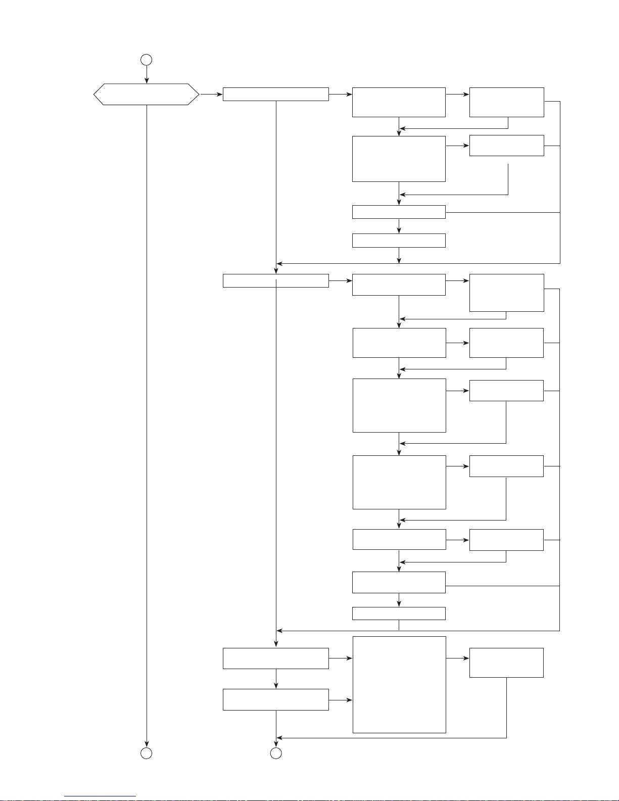
9. Troubleshooting procedure
1) Failure diagnosis fl owchart
Do any of the following
errors appear on the
humidity indicator?
“E0” “E1” “E2” “E3” “E4”
“E5” “E7” “E8” “A1” “A2”
“A6” “A8” “P4”
Perform the recommended
actions described in “Error
Indications and Corrective
Actions” on page 16.
Check the continuity of current
fuse on the power supply board
FUSE1 : 10A FUSE2/3 : 2A
CHILD LOCK indicator
turns on
When the POWER switch is
turned ON, does the operating
mode lamp turn on?
Deactivate the child lock
Check the power cord conduction
Replace the power cord
Replace the power
supply board
Does the detection buzzer
beep when the POWER
switch is turned ON?
Check if the lamps on the
control panel turn on.
* How to turn on all of the
lamps (See “LED and
Monitor indicators” on
page 17)
* Check whether any of the
LEDs on the operation
control board have fallen
off (repair if an LED has
fallen off)
Check that the power
supply board, control
board and operation
control board connectors
are fi rmly connected
(carefully check whether
any of the connector pins
have been pulled out,
etc.).
Firmly insert the
connectors or
connector pins in
the trouble spots
Replace the operation
control board
Replace the control
board
Replace the power
supply board
Is the FULL lamp lit?
Is the tank full?
Drain the water from the tank
Float check:
• Is the fl oat switch disconnected
or installed reversely?
• Is the fl oat operation smooth?
• Is there a magnet attached
to the fl oat?
Repair the fl oat problem
Check the fl oat switch
• Check the control board
P12 connector insertion
and the connector pins
• Check the continuity
between the P12
connector terminals when
the water tank is installed
Normal . . . When tank is
full: shorted
When tank is empty: open
Replace the fl oat switch
Replace the control board
Replace the power
supply board
A
YES
YES
NO
NO
YES YES OK
NG
NG
OK
OK
OK
NG NG
NG
NG
NG
OK
OK
NGNO
OK
OK
NG
NG
NG
OK
NG
NG OK
OK
OK
OK
YES
YES
NO
NO
YES
YES
NO
Page 11
11
Check the power supply
board P7 connector insertion
and the connector pins
Is dehumidifi cation
taking place?
Is the blower fan motor rotating?
A
Firmly insert the
connectors or
connector pins
Check the resistance values
for the blower fan motor.
Normal:Between yellow and blue 217-236Ω
Between black and blue 219-237Ω
Abnormal:Open or shorted
Replace the blower fan motor
Replace the control board
Replace the power
supply board
NO
YES
NO NG
NG
NG
NG
OK
OK
NG
OK
OK
YES
B
Does the compressor operate?
Check the power supply board P2
and P3 (run capacitors) connector
insertions and connector pins
Raise the humidity in the
usage environment and check.
(Compressor stopped due to
abnormally low temperatures)
Firmly insert the
connectors or
connector pins
Check the motor protector
continuity
Normal: shorted
Abnormal: open
* Check it at normal temperature
with the power OFF.
Is the operating environment low
temperature (below 3.2°C)?
Check the resistance
values for the compressor
Normal: 24 to 27 Ω
between C-R
40 to 45 Ω
between C-S
Abnormal: Open or shorted
Is there an overcurrent?
(Surface is hot)
Replace the power supply
board
Replace the control board
Replace the motor
protector
Replace the
compressor
Replace the
compressor
NO
YES
YES
NO
OK
OK
OK
OK
NG
NG
OK
NG
OK
NG
NG
NG
NG
NG
OK
OKYES
OK
OK
NG
NO
Is the heat exchanger
(evaporator) cold?
Are the power consumption
and current normal?
Check the refrigerant
circuit (Leaks or blockages)
• The part of the cooler
near the tube temperature
sensor should be at least
10°C lower than room
temperature when normal.
• If the amount of
refrigerant is low due to
a slow leak, white frost
appears on the bottom
of the heat exchanger
Replace the parts
responsible for the
leaks or blockages
NO
NO
NG
OK
YES
C
YES
Page 12

12
B
D
The unit stops working
in the middle of operation
Check the resistance values
for the tube temperature.
Normal: 8.0KΩ to 20.8KΩ
(Between P15 pins)
Abnormal: Open or shorted
Check the resistance values
for the solenoid valve.
Normal: 2.0KΩ to 2.2KΩ
(Between the pin1 and pin2)
Abnormal: Open or shorted
Replace the tube
temperature thermistor
Replace the solenoid valve
The louvre does not
swing
C
Is the fi lter blocked due to dust, etc.?
Is the operating environment low
humidity or low temperature?
The main unit is operating
normally.
Check the operating environment
again, and then operate again.
Is the operation being
performed with the unit set to
automatic operating mode?
(LAUNDRY/MILDEW
GUARD/AUTO/OFF TIMER)
① LAUNDRY: A minimum of about 84 minutes to a maximum of about 12 hours
② MILDEW GUARD: A minimum of about 4 hours to a maximum of about 12 hours
③ AUTO: If the current humidity goes lower than the set humidity, operation stops.
④ OFF TIMER: Has the timer stopped operating? Operation stops at the set time.
⑤ Is the OFF timer being used at the same time as timer OFF for all operating modes?
Operation stops at the set time as timer operation is given priority.
The main unit is operating normally if ① through ⑤ are true.
Is the up-down swing louvre
OFF?
Check the connector connection
between the control board P11
connection and the stepping motor
connector and connector pins.
Check the resistance values
between the stepping motor
connector pins.
Normal
Terminals 1-2
Terminals 1-3
342Ω to 418Ω
Terminals 1-4
Terminals 1-5
Abnormal
Open or shorted
E
Replace the control board
Replace the control board
Replace the power supply board
Replace the power supply board
Clean fi lter
Normal. Dehumidifi cation
may not be possible in low
humidity and low temperature
environments.
Explain the performance curve
on page 8.
Is the dehumidifi er installed
in a low humidity, low
temperature environment?
Does the up-down swing
louvre change to Wide,
Frontward, and Upward?
Firmly insert the
connectors or connector
pins in the trouble spots
Replace the stepping motor
Dehumidifi cation
may not be possible
in a low humidity,
low temperature
environment. Explain
the performance
curve on page 8.
Normal
Replace the control
board
Replace the power
supply board
OK
OK
OK
OK
NG
NG
YES
OK
OK
NO
YES
NO
OK
NG
NG
NG
NG
NG
YESYES
YES
NO
YES YES YES
NO
NO
NO
OK
OK
NG
NG NG OK
OK
NO
OK
OK
NG
Page 13

13
D
F
MOVE EYE operation
is abnormal
Is the left-right swing louvre
stopped?
Normal
E
YES
NO
Does the left-right swing
change to Wide and Stop
swing operation?
Check the connection
between the control board
P9 connector and the
stepping motor as well as the
connector pins.
Firmly insert the
connectors or connector
pins in the trouble spots
Check the resistance values
between the stepping motor
connector pins.
Normal
Terminals 1-2
Terminals 1-3
342Ω to 418Ω
Terminals 1-4
Terminals 1-5
Abnormal
Open or shorted
Replace the stepping
motor
Replace the control
board
Replace the power
supply board
Is the operating mode the
MOVE EYE operating mode?
Is the MOVE EYE monitor on
the control panel lit?
Check the control board P40
connector insertion and the
connector pins
See “LED and Monitor indicators” on page 17 of the Troubleshooting
procedure. Press the MOVE EYE switch and the DEHUMIDIFY
switch 4 times at the same time when the POWER switch is OFF,
and then set the POWER switch to ON within 2 seconds.
After it starts up, select the mode with the TIMER switch. Press the
TIMER switch 6 times to select the mode 6. (the selected mode
number is displayed in the timer display)
Check method: Cover the MOVE EYE sensor with the palm of the
hand, and check whether the humidity display shows approximately 35.
Replace the move eye
How to check the MOVE EYE and louvre operations: Hang a wet
towel on a wall with no window or heat source.
Run with the dehumidifi er operating mode set to LAUNDRY
operating mode. Check that the MOVE EYE monitor is lit. MOVE
EYE and louvre operation is normal if 3 minutes after it starts up,
the area where air blows out from the main unit gradually narrows
and the air hits the centre of the towel being dried.
MOVE EYE is OFF. Turn the POWER switch
OFF and press the MOVE EYE switch for about 3
seconds. When the detector beeps and the MOVE
EYE operating mode is set to LAUNDRY or MILDEW
GUARD, does the MOVE EYE monitor turn on?
Normal
Repair the control board
P40 connector
Replace the control board
Replace the power supply
board
YES YES
NG
NO
OK
NO
OK
OK
NG
NG
OK
OK
OK
NG
NO YES
YES
NO NO
YES
YES
OKNG
NO
OK
OK
NG
OK
OK
NG
NG
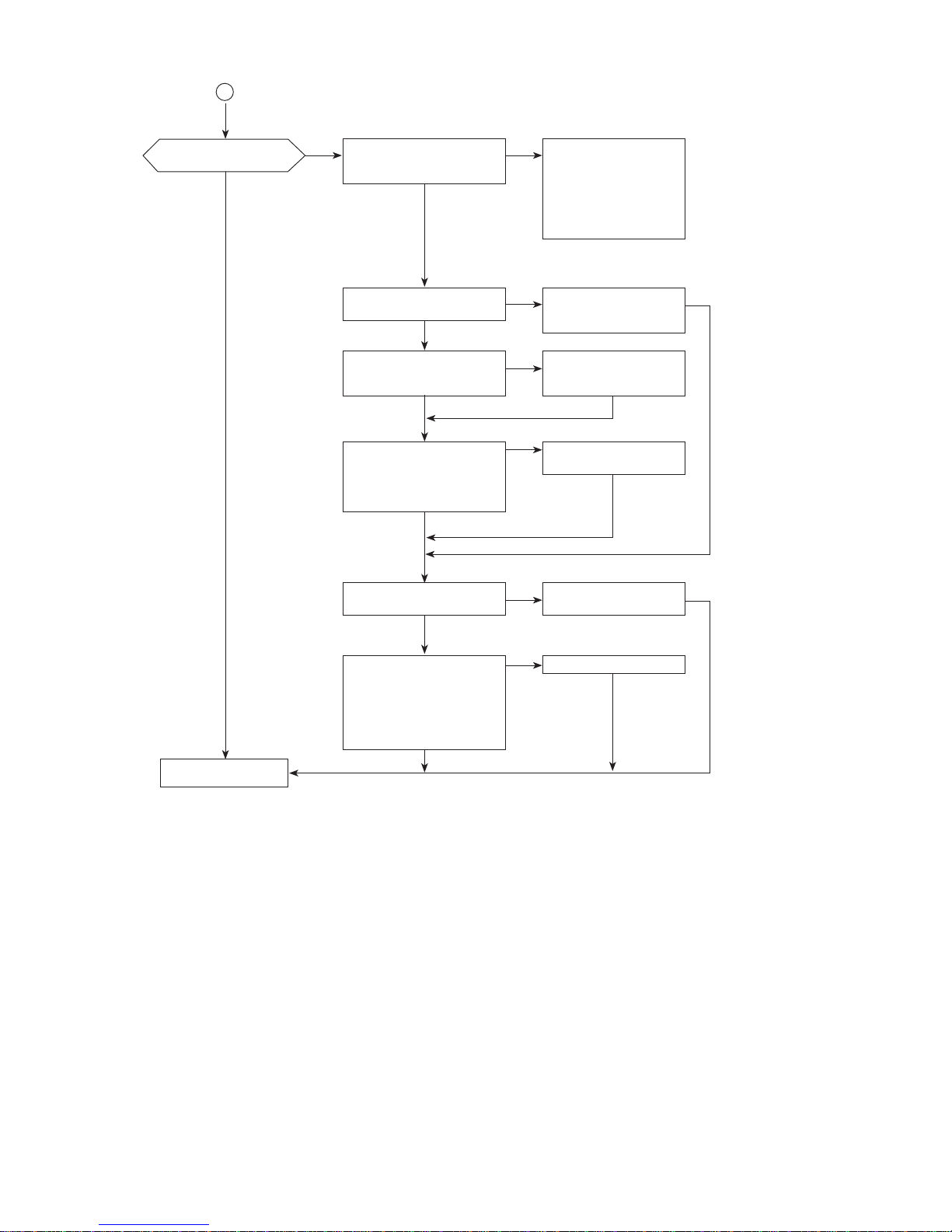
Page 14
14
F
Amount of
dehumidifi cation is low
Is there dust or dirt on the
room temperature sensor?
YES
NO
Replace the room
temperature sensor
Remove the dust or
dirt from the room
temperature sensor
Check the control board P13
connector insertion and the
connector pins
Firmly insert the
connectors or connector
pins in the trouble spots
Check the resistance values for
the room temperature sensor
Connector pins (between 3-4)
Normal: 8 to 20.8KΩ
Abnormal: Open or shorted
Is there dust or dirt on the
humidity sensor?
Remove the dust or dirt
from the humidity sensor
Replace the control board
Check the humidity sensor
operation
(Hold a steaming towel or hot
air from a dryer close to the
humidity sensor for 1 minute.
If the humidity indicator rises,
it is OK.)
Normal
YES
YES
NG
NG
YES
NG
NO
NO
OK
OK
NO
OK
OK
OK
Is the dehumidifi er installed
in a low humidity, low
temperature environment?
The unit is normal.
Dehumidifi cation may
not be possible in a
low humidity and low
temperature environment.
Explain the performance
curve on page 8.
OK
OK
OK
Page 15

15
2) Simple Check Table for Main Parts
Part name Test criteria
Tube temperature
detection thermistor
Disconnect the connector and measure the resistance values with a tester (Part temperature
10°C to 30°C).
Normal Abnormal
8.0KΩ to 20.8KΩ Open or shorted
Room temperature
sensor
Disconnect the connector and measure the resistance values with a tester (Part temperature
10°C to 30°C).
Normal .............8.0 to 20.8KΩ (between pins 3-4)
Abnormal .........Open or shorted
Compressor
Disconnect the connector and measure the resistance values across terminals with a tester
(Coil temperature 10°C to 30°C).
Normal Abnormal
C-R side 24Ω to 27Ω
Open or shorted
C-S side 40Ω to 45Ω
Blower fan motor
Measure the resistance values across terminals with a tester (Part temperature: 10°C to
30°C).
Normal Abormal
Yellow-Blue 217Ω to 236Ω
Open or shorted
Black-Blue 219Ω to 237Ω
* Be careful of injury or shock
Solenoid valve coil
Measure the resistance values across terminals with a tester (Part temperature: 10°C to
30°C).
Normal Abnormal
2.0KΩ to 2.2KΩ Open or shorted
Stepping motor
Measure the resistance values across terminals with a tester (Part temperature: approx
25°C).
Normal Abnormal
Terminals 1-2
342Ω to 418Ω Open or shorted
Terminals 1-3
Terminals 1-4
Terminals 1-5
Page 16

16
3) Error Indications and Corrective Actions
Indicator
(current humidity
display)
Error (failure) Corrective action
A1
Microprocessor failure
RAM error
Replace the control board
A2 Frequency determination error
Check the outlet, 220V power
(Try to replace the power supply and control
boards)
A6
Watchdog error
(Main stop/Interrupt)
Replace the control board
A8
E
2
PROM failure
Replace the control board
E0
Room temperature sensor
disconnected
Check the P13 connector connection
Check the room temperature sensor board
E1 Room temperature sensor short
E2
Move eye thermopile
OBJ High temperature abnormal
(object temperature)
Check the connectors
Replace the move eye thermopile
E3
Move eye thermopile
OBJ Low temperature abnormal
(object temperature)
Check the connectors and the disconnection
Replace the move eye thermopile
E4
Move eye thermopile
AMB High temperature
abnormal (ambient temperature)
Check the connectors
Replace the move eye thermopile
E5
Move eye thermopile
AMB Low temperature abnormal
(ambient temperature)
Check the connectors and the disconnection
Replace the move eye thermopile
E7
Tube temperature thermistor
disconnected
Check the connectors
Check the P15 tube temperature thermistor
connection
E8
Tube temperature thermistor
short
P4 Compressor failure
Check the air fl ow
Check the tube temperature thermistor
Check the compressor operating noise
4) Self Diagnostic Test Program
(1) Deactivate 3-minute restart prevention
Start . . . . . . . . . .Press the MOVE EYE and DEHUMIDIFY switches together 3 times when
the power is off. Press the POWER switch within 2 seconds.
Functions . . . . . . .① Deactivates 3-minute restart (immediate operation)
② Sets the operating mode to LAUNDRY
③ When E2PROM error is detected, FULL LED and CHILD LOCK monitor
are lit.
④ Turns the solenoid valve ON for 3 seconds when the power is off, and
then after 3 seconds, turns the solenoid valve OFF.
⑤ When the operating mode changes, it fi xes the fan rank and unlocks the
E2PROM error display.
Finish . . . . . . . . .Turn the power OFF.
Page 17

17
Microprocessor
version display
Current
humidity
indicator
Room
temperature
indicator
(1°C increments)
Room temperature
indicator
(0.2°C increments)
Tube temperature
indicator
(1°C increments)
Tube temperature
indicator
(0.2°C
increments)
Move eye
thermopile
OBJ indicator
(1°C
increments)
Move eye
thermopile
OBJ indicator
(0.2°C
increments)
MOVE EYE
AMB indicator
Fan rank
indicator
Blower fan
operation
cumulative time
(Top 8 bits)
Blower fan
operation
cumulative time
(Bottom 8 bits)
Current
sensitivity
table
7 seg + All
LEDs lit
(2) LED and Monitor indicators
Start . . . . . . . . . .Press the MOVE EYE and DEHUMIDIFY switches together 4 times when
the power is off. Press the POWER switch within 2 seconds.
Mode selection . . . .Use the TIMER switch to change the diagnostic mode (0 to 13). The selected
mode number is displayed in the timer display.
Finish . . . . . . . . .Turn the power OFF.
How to display the humidity
indicator by diagnostic mode
In decimal : 0, 1, 2, 4, 6, 8, 9, 10, 13
In hexadecimal : 3, 5, 7, 11, 12
(3) Demo mode
Start . . . . . . . . . .Hold the MOVE EYE and DEHUMIDIFY switches together when the power
is off and press the POWER switch.
Operations . . . . . .① Demo mode continues until the microprocessor is reset
② All of the switches are disabled
③ Operates the same way as when in LAUNDRY mode except for the
compressor and the blower fan.
Finish . . . . . . . . .Turn the power OFF.
(4) Error history check mode
Start . . . . . . . . . .Press the MOVE EYE and DEHUMIDIFY switches together 5 times when
the power is off. Press the POWER switch within 2 seconds.
Mode selection . . . .Use the TIMER switch to change the diagnostic mode (0 to 7).
Operations . . . . . .① Mode 0: Newest error history display
② Mode 7: Oldest error history display
Finish . . . . . . . . .Turn the power OFF.
Page 18

18
Note) This page is extracted from the instruction manual.
10. T roubleshooting
Page 19

19
Note) This page is extracted from the instruction manual.
Page 20

20
11. Maintenance
Note) This page is extracted from the instruction manual.
Page 21

21
12. Service Checklist
(1) Points to be checked after completing repairing
After completing repairing, check the all items below to prevent re-repair.
Check items Check
At installation
Was the proper tool used?
Are the parts on the parts catalog used?
Verify that there is no problem in the lead wire (layout and connection) and/or clamp.
Verify that there is no defect, such as lead wire caught in other parts, damage, and/or intermediate connection.
Verify that there is no defect, such as deteriorated or damaged power cord and/or intermediate connection.
Verify that there is no slack and/or damage to power cord.
Are the connectors and metal terminals inserted securely?
Verify that there is no abnormal sound of the motor etc.
If electrical parts are replaced, was the insulation performance checked?
Verify that there is no insuffi cient inserting or gap in the fi tting and/or calking sections.
Is the cushioning attached without fail? Is the parts requires silicon coating surely coated with silicon?
Are the all sorts of specifi ed screws on the parts catalog used?
Are the all sorts of packing, washers, etc. installed without fail?
Are the waterproofi ng and rust prevention performed on the products which require those treatment?
Installation conditions
Is the unit installed at the fl at place?
Is the unit installed at the stable place? (The unit is not easy to fall down?)
Is a fi rm ground selected for the installation place? (Be careful with a hollow fl oor, corrosion, etc.)
Is there enough space around the unit? (Is there no wall, ceiling, curtains, etc. near the unit?)
Verify that the unit is not installed where it is exposed to direct sunlight or near heat- generating devices.
Verify that the unit is not installed in a special environment. (places where chemicals are used or there is a lot of dust.)
Is the product which requires earthing correctly earthed? (Do not connect the earth wire to a water pipe or gas pipe.)
Is the installation criteria described in the instruction or installation manual fulfi lled?
Operation check
Is the power on when you turn it on?
Is the basic operation described in the instruction manual successfully performed?
Verify that there is no problem in operation around the open and close part, rotation part, slide part, etc.
Verify that no abnormal sound or smell is emitted.
Is the power off when you turn it off.
Explanation
after repair
Explain the content of repair, check, and/or adjustment to the customer well.
Tell the customer to read the instruction manual well to use this dehumidifi er.
Tell the customer not to disassemble the product.
Explain to the customer if the installation place is not good or if there is more effi cient way.
Page 22

22
13. Precations for Disassembly and Reassembly
The following precautions should be observed in order to perform disassembly and reassembly safely and correctly.
The following diagrams indicate circumstances where danger can result from mishandling the unit.
WARNING
Mishandling may result in fatal or serious injury, or fi re.
CAUTION
Mishandling may result in injuries or damage to your home or property, etc.
Forbidden
Always follow the
instructions
Alert
Meanings of graphic symbols are explained below.
Remove the power plug
from the socket.
Failure to do so may cause electric shock or injuries.
When replacing parts,
use the specifi ed partslisted
on the parts catalog.
Failure to do so may cause combustion,
moke, and/or malfunction,
Do not touch a rotating object
until it completely stops.
The rotating object may catch your hand etc,
and result in injuries.
Do not work with wet hands.
This may cause electric shock.
Check the wiring diagram
before wiring processing.
Failure to do so may cause combustion,
generation of smoke, and/or malfunction.
After the work,
lay the wire out as it was before.
Failure to do so may cause combustion,
generation of smoke, and/or malfunction.
Do not alter the product.
This may cause fi re, electric shock, and/or injuries.
Comply with the law.
Follow the applicable laws and regulations,
such as "Fire Prevention Ordinance" and
"Electric Equipment Technical Standards."
Failure to do so may cause fi re and electric shock.
Use appropriate tools.
Failure to do so may result in
an accident caused by contact failure or
loose parts.
Earth the product which
requires earthing correctly.
Incomplete earthing or connection to
a gas pipe, water pipe, etc.
may cause an explosion or electric shock.
Do not damage or process
the power cord or lead wire.
This may cause fi re, combustion,
and/or electric shock.
Replace the damaged or
deteriorated power cord or
lead wire.
Failure to do so may cause fi re,
combustion, and/or electric shock.
Unplug
Return to
as it was
Don't touch No wet hands
Check Return to
as it was
No alteration Obey the law
Use proper
tools
Earth
Forbidden
Replace
WARNING
Page 23

23
Wear protective gloves.
Failure to do so may result in injuries
by the edge of metal, electric shock,
and/or burns caused by contact with hot section.
Keep children away.
Failure to do so may result in
electric shock and/or injuries when moving
the unit or using a measuring device.
Do not put the unit
where it may burn.
This may cause fi re,
or combustion.
Check the fi rmness
of installation location.
The product may fall down,
which could cause an accident or injuries.
Perform operation
check after reassembly.
Failure to do so may result
in an accident or malfunction.
Do not wash the unit
with water.
This may result in fi re,
combustion, or malfunction
Wear gloves Keep away
Do not
install unit
Check
Operation
check
No water
CAUTION
1. When the service requires disassembly, be sure to remove the power cord from the outlet.
2. When it is necessary to perform the work with the power on, be careful not to touch the live part.
3. Use appropriate tools for the work.
4. Use the specifi ed parts listed on the "Parts Catalog" of the applicable model.
5. Check the deterioration of the power cord and lead wire at service.
Replace the damaged or deteriorated power cord and lead wire.
6. After the service, perform the operation check.
Verify that the tank full detection works properly and the unit operates without a problem.
Safety precautions for the inspection and service
Page 24

24
(2) Removing the fi lter cover and rear casing assembly
① Remove the water tank. → (See (1)
Removing the water tank)
② Push the tab on the fi lter cover up,
pull it forwards, and remove the fi lter
cover. → (Removing the fi lter cover)
③ Remove the rear casing set screws
(6) and special screws(2). Detach
the catch(1).
④ Remove the rear casing.
<Precautions for Assembly>
When assembling the rear
casing, be careful not to pull out
the lead wires around
the control board.
14. Disassembly and Reassembly Hints
[Precautions for Assembly]
• Firmly connect the lead wire connectors. Firmly tighten the screw connectors in particular.
• If the binding band holding the lead wires is cut, it must be replaced with a new binding band.
• Hold the lead wires that were removed in place with a clamper, etc. and do the wiring.
(1) Removing the water tank
① Pull out the water tank from the side
bottom of the unit. → (Removing the
water tank)
①
Water tank
Main
unit
②
④③
Filter
cover
Rear
casing
Pull it straight out because it is
on rails
Rear casing
set screws (6)
Catch (1)
Ta b
Special
screws (2)
Page 25

25
(4) Removing and replacing the operation control board/louvre assembly
① Remove the front casing. → (See (3)
Removing the front casing)
② Disconnect connectors P9, P11,
P13, P15, P20, P21, and P40 from
the control board on the right side of
the main unit.
③ Remove the louvre assembly.
④ Remove the top cover set screw
(1), and remove the top cover. →
(Removing and replacing the room
temperature thermistor)
⑤ Remove the operation control board
set screws (2) from the louvre
assembly, unlatch the catches (2),
and remove the operation control
board. → (Removing and replacing
the operation control board)
(3) Removing the front casing
① Remove the water tank. → (See (1)
Removing the water tank)
② Remove the rear casing assembly.
→ (See (2) Removing the fi lter cover
and rear casing assembly)
③ Remove the front casing set screw
(1) from the side of the main unit.
④ Release the catch on the bottom of
the front casing, hold both sides,
release the left and right catches (3)
so it opens, pull it forwards, release
the blower fan frame catches (5),
and remove the front casing. →
(Removing the front casing)
<Caution>
The catch on the casing may be
damaged, so push the catch in ④
A on the rear casing to release it to
open the casing.
③
Front casing set
screw (1)
②
⑤
④④
③
⑤
Catches
Front
casing
Front casing
bottom catch
Front casing inside
catches (5)
Left/right
catches
(3)
A
Louvre assembly
Top cover
Room
temperature
thermistor
Operation control
board set screws (2)
Top cover set
screw (1)
Operation control board
Catches (2)
④
Right side of main
Right side of main
unit
unit
Control
board
Page 26

26
(5) Removing and replacing the control board
① Remove the front and rear casings.
→ (See (2) Removing the fi lter cover and
rear casing assembly, and (3) Removing the
front casing)
② Disconnect all of the connectors (P9, P11,
P12, P15, P20, P21, P40, and P50) from the
control board, and gently lift and slide the
control board out.
<Precautions for Assembly>
Gently push the casing rib, and at the same
time, insert the board into the groove.
Install the lead wires as shown in ②.
(6) Removing and replacing the power supply board
① Remove the front and rear casings.
→
(See (2) Removing the fi lter cover and rear
casing assembly, and (3) Removing the front casing)
② Remove the board cover T set screw (1), and
pull out the power supply board assembly.
→ (Removing and replacing the power
supply board)
<Precautions for Assembly>
Do not forget the lead wires that are held
together.
Install the lead wires as shown in ②.
③
Remove the board box, and disconnect all of
the connectors (P1, P2, P3, P7, P8, and P30).
④ Remove the power supply board set screw
(1), and remove the board.
→ (Removing and replacing the power
supply board)
<Precautions for Assembly>
Be sure to attach new waterproof tape
(fi lament tape, 19 mm) after peeling off the
old waterproof tape.
②
Press the casing rib with
your fi ngers and pull out
the board
②
④
③
Control board
Slide
Slide
Disconnect all of the connectors
Board cover T
Board box Waterproof tape
Power supply board Capacitor
Power supply
board set
screw (1)
Board cover U
Board cover
T set screw (1)
* Bind the lead wires together
Page 27

27
(7) Removing and replacing the blower net and the blower motor
① Remove the board holder from the board
assembly.
→ (See (6) Removing and replacing the
power supply board)
② Remove the net.
③ Disconnect the P7 connector from the
power supply board.
④ Remove the casing set screws (2), and lift
up the casing to remove it.
⑤ Remove the blower fan stop nut, and
remove the blower fan.
②③
④⑤
Power supply board
Remove connector P7
Net
Casing set screws (2)
Nut
Blower fan
Casing
⑥ Remove the blower motor holding plate set
screws (4), and remove the blower motor.
→ (Removing and replacing the
blower motor)
<Precautions for Assembly>
The motor lead wires must pass through
the casing catch.
(8) Removing and replacing the power plug
① Remove the board holder from the power
supply board assembly. → (See (6)
Removing and replacing the power supply
board)
② Disconnect connector P1 from the power
supply board.
③ Remove the earth wire set screw(1), and
remove the power cord earth wire.
④ Remove the power cord from the main
unit clamper, and remove from the bottom
groove. → (Removing and replacing the
power plug)
<Precautions for Assembly>
When installing the earth wires, give them
some slack.
⑥
Blower motor holding plate set screws(2)
②
③④
Blower motor
holding plate
Blower motor holding plate
set screws(2)
Note:
The motor lead wires must
pass through the casing catch.
Blower motor
Remove connector P1
Power supply board
Power plug
Earth wire set screw (1)
Page 28

28
(10) Removing and replacing the fl oat switch
① Remove the blower fan assembly.
(See (7) Removing and replacing the
blower net and the blower motor)
② Remove the connector P12 on the control
board.
③ Remove the fl oat switch set screw(1) from
the drain pan assembly to remove the fl oat
switch.
→ (Removing and replacing the fl oat
switch)
②
③
Remove the
connector P12
Control board
Float switch
Float switch
set screw(1)
Float
switch
Float
switch
set screw
(9) Removing and replacing the solenoid valve
① Remove the board holder from the power
supply board assembly. → (See (6)
Removing and replacing the power supply
board)
② Disconnect connector P6 from the power
supply board.
③ Remove the solenoid valve set screw(1) to
remove the solenoid valve. → (Removing
and replacing the solenoid valve)
②
③
Remove connector P6
Power supply board
Solenoid valve set screw (1)
Solenoid valve
Page 29

29
(12) Removing and replacing the compressor/heat exchanger
① Remove the drain pan assembly.
→ (See (10) Removing and replacing the
drain pan assembly)
② Place a support under the bottom right of
the heat exchange assembly, and remove
the compressor set screws (3).
③ Remove the compressor and the heat
exchange assembly from the base. →
(Removing and replacing the compressor/
heat exchange assembly)
<Precautions for Assembly>
• When the power supply board earth wire and power cord earth wire are installed, line up the fl at
surfaces of the round terminals as shown in the illustration below.
• Be careful about the installation position for the tube temperature thermistor.
• Install the lead wire for the tube temperature thermistor so that the lead wire does not touch the
heat exchanger.
(11) Removing and replacing the drain pan assembly
① Remove the blower fan assembly.
→ (See (7) Removing and replacing the
blower net and the blower motor)
② Release the drain pan catches (4) from the
base, and remove the drain pan assembly
while holding the heat exchange assembly
away from the main unit. → (Removing
and replacing the drain pan assembly)
<Precautions for Assembly>
• When replacing the drain pan, do not
forget to install the cushions, etc.
In particular, the drain outlet packing is a
countermeasure against water leaking,
so be sure to install it.
②
Drain pan
assembly
②
③
Heat exchange assembly
Compressor
Base
Compressor
set screws(3)
Power supply board earth wire
Power cord earth wire
Power supply board earth wirePower cord earth wire
Gray (R)
White (C)
Red (S)
<Compressor: Wiring diagram>
Support
Page 30

30
(13) Removing and replacing the louvre assembly
① Remove the front casing. → (See (3)
Removing the front casing)
② Remove the operation control board from
the louvre assembly. → (Removing and
replacing the operation control board)
③ Remove the top cover set screws (2) from
the louvre assembly, and remove the top
cover.
④ Remove the gear holder set screws (3),
and remove the gear holder.
⑤ Remove the gear and the stepping motor.
⑥ Remove the sleeve G1 set screws (2), and
remove the sleeve G1.
⑦ Remove the top casing and the louvre
assembly.
If the louvre U assembly is in the way,
push out the shaft louvre with a narrow
rod ( 1 to 3), and remove the louvre U
assembly.
⑧ Gently open both ends of louvre CY-2 and
louvre CY-3, and remove the louvre.
Remove the MOVE EYE set screw (1),
release the left and right CY-1 louvre
catches, and remove the louvre while
pulling out the fi n shaft.
⑨ Remove the louvre CY-N linked fi ns joint,
and remove the linked fi ns.
⑩ Remove the mount MS set screw(1), and
remove the mount MS.
⑪ Remove the stepping motor set screws
(2), and remove the stepping motor.
⑫ Remove the MOVE EYE set screw (1),
and remove the MOVE EYE.
Top cover set screws(2)
③④
⑤⑥
⑦⑧
⑩
⑫
⑨
Gear holder
Gear holder set screws(3)
Gear
Stepping motor
Sleeve G1 set screws(2)
Top casing
Louvre
CY-2
Louvre
CY-3
Louvre U
assembly
Louvre assembly
Link fi n
Louvre CY-N
Mount MS set screw(1)
Stepping motor
set screws(2)
MOVE EYE
set screw(1)
⑪
Louvre
CY-1
Louvre
CY-N
Page 31

31
Louvre/gear assembly procedure
① Raise the louvre assembly so that the gear does
not drop.
② Place each of the louvres CY-1, CY-2, and CY-3
in the upward position, and line up the protrusions
with the markings on the top casing.
③ Run the lead wires through gears L3, L2, and L1, and line up the gear notches with the markings .
④ Insert the gear L3, L2, and L1 grooves into the protrusions of respective louvre CY-1, CY-2, and CY-
3.
⑤ Hold the louvre so that gears L3, L2, and L1 do
not turn and at the same time, line up the gear M
notch in the upward direction and attach.
If the gear position shifts even one tooth, the
louvre open/close position shifts.
If gears L3, L2, and L1 are allowed to move in
the direction of the arrows, it is easier for them
to fi t together.
⑥ Install the stepping motor and gear SM.
⑦ Run the lead wires through the gear holder hole,
and tighten the gear holder set screws (3).
③
④
⑤
⑥
Upward
position
Line up the
protrusions
on louvres
CY1, CY2,
and CY3
with the
markings
on the top
casing.
Louvre
protrusions
Gear
notches
Lead
wires
Gear L1
Gear L2
Gear L3
Gear M notch
*Gear runout direction
Stepping
motor
Gear SM
Gear holder set screws(3)
②
⑦
Page 32

32
Operation Checks
① When the side of the move sensor assembly is
held and rotated left and right about 60 degrees
(a total of 120 degrees), the fan must move
smoothly in sync.
② When louvre N is held and rotated by hand, it
must operate smoothly with no unusual noises.
③ At the upward position (until the top casing is
slanted), the louvre CY-N must open.
④ The louvre CY-N top edge must be at the parting
position at the stop position.
⑤ The louvre CY-2 front edge must be at the
difference position at the stop position.
⑥ The louvre CY-3 front edge must be at the
stopper position at the stop position.
⑦ Louvre CY-1, CY-2, and CY-3 must have no
gaps.
<Precautions for Assembly>
• When the move sensor assembly side is held and rotated left and right 60° (a total of 120°), adjust
the length of the sensor lead wires so that they do not become taut, and secure with tape.
① Left and right 60°
② Rotate up and down
Gear holder
⑤ Difference position
⑥ Stopper position
④ Parting position
Louvre CY-N
Give them some slack
Filament tape
MOVE EYE
Rotate left
and right 60°
Page 33

33
Page 34

34
MJ-E14EG-S1-IT Model Structural Disassembly Diagram
[
Casing and Tank Structure
]
109
147
138
136
106
107
108
110
101
105
104
111
112
144
114
113
128
119
103
102
117
118
142
143
127
124
120
121
122
123
129
130
131
140
132
133
135
126
125
139
145
146
134
136
137
107
108
SCW-PL-TBFZR
4×12(1)
SCW-PL-TBFZR
4×12(6)
TBFZR
3×10M(2)
SCW-PL-TBFZR
4×12(2)
SCW-DPFZR-PT(White)
3×10(1)
SCW-TPFZR
3×8N(3)
SCW-DPFZR-PT
3×10(1)
SCW-PL-TBFZR
4×12(2)
SCW-TBFZR
3×10M(1)
SCW-PL-TBFZR
4×12(1)
SCW-PL-TBFZR
4×12(3)
141
116
SCW-MPFZR
M4×14-TORX(2)
115
15. Parts Catalog
Page 35

35
Notes:
1. Circled reference numbers indicate performance parts.
2. New parts and the parts that are used only with these models lack compatibility.
3. Those parts that are marked by and are of critical importance for sustaining safety and performance.
Use specified parts at replacement.
4. When ordering parts without part numbers, use the design number. The order may take a while to process.
*1. If the part is out of production, you may be required to use a common part.
*2. Parts found installed in products may have a different part number from service parts.
However, there should be no difference in performance and can be installed.
101
102
103
104
105
106
107
108
109
110
111
112
113
114
115
116
117
118
119
120
121
122
123
124
125
126
127
128
129
130
131
132
133
134
135
136
137
138
139
140
141
142
143
144
145
146
147
1
1
1
1
1
1
2
2
1
1
1
1
1
1
1
1
1
1
1
1
1
1
1
1
1
1
1
1
1
1
1
1
1
1
1
4
2
1
1
1
1
1
1
1
1
1
1
7*110*T5
7*170*T5
Badge attached
7*70*T5
L 345
expendable item
E80EX-H
E80EX-H
100EX
100EX
H100CX
10HGX
100EX
100EX
E105EF-TW
100EX
100EX
100EX
E80EX-H
10HGX
E14EG-E1
E14EG-E1
100EX
100EX
100EX
100EX
100EX
100EX
100EX
10HGX
10HGX
E14EG-E1
100GX
100GX
100EX
100EX
H100CX
100EX
E80EX-H
100EX
100EX
E14EG-E1
100EX
10HGX
E80EX-H
100EX
E105EF-TW
E80EX-H
M22 C75 345
M22 C75 345T
M22 B56 320TC
M22 B56 330
M22 B46 340
M22 B70 310R
M22 B56 0553
M22 B56 0556
M22 C81 310
M22 B56 0555
M22 B56 180
M22 B56 321F
M22 C75 310
M22 C95 689
M22 B70 320
M22 C98 555
M22 C95 440
M22 C98 311
M22 B56 261G1
M22 B56 261GW
M22 B56 110L1
M22 B56 110L2
M22 B56 110L3
M22 B56 110M
M22 B56 110
M22 B70 620
M22 B70 260
M22 C98 405
M22 B66 405CY2
M22 B66 405CY3
M22 B56 405CY1
M22 B56 261
M22 B46 620S
M22 B56 110
M22 C75 405CYN
M22 B56 405
M22 B56 405S
M22 C98 150
M22 B56 183
M22 B70 405L
M22 C75 100
M22 B56 370
M22 C81 449
M22 C75 349
M22 C95 450
M22 C75 468
M22 C95 936
TANK*ASSY-EX
TANK*EX
COVER-TANK*EX
LID-TANK*EX
FLOAT*ASSY-CX
CASE-R*E105EF
PACKING-PCA*EX
PACKING-PCA*EX
CASE-F-ASSY-2*E105EF
PACKING-PCA*EX
HANDLE*EX
COVER-FILTER*ASSY-EX
CASE-T-SUB*ASSY-E80X
PCA*MJ-E14EG-S1-IT
COVER-T*GX
THERMISTOR-RT*HGX
ESC-SW*E14EG-IT
CASE-T*EEF
SLEEVE-G1*EX
SLEEVE-GM*EX
GEAR-L1*EX
GEAR-L2*EX
GEAR-L3*EX
GEAR-M*EX
GEAR-SM*EX
STEPPING-MOTOR-2-HX
HOLDER-GEAR*HGX
LOUVER*ASSY-EX
LOUVER-CY-2*GX
LOUVER-CY-3*GX
LOUVER-CY-1*EX
MOUNT-SM*EX
STEPPING-MOTOR*CX
GEAR-SM*EX
LOUVER-CY-N*EX
FIN*EX
FIN-S*EX
SENSOR-TP*ASSY-EX
LINK-FIN*EX
LOUVER-U-ASSY*HGX
SHAFT-LOUVER-SWRM*EX
REINFORCE-PL*EX
CLEAR-PLATE*E80EX
AIR-FILTER*ASSY-E80X
NAME-PL*E14CG-S1-IT
ESCUTCHEON-PL*E80EX
I.B*E14EG-S1-IT
Part NO.
Part name
Compatibility Miscellaneous
Safety
Part
Pc/1
unit
New
New
New
New
Model MJ-E14EG-S1-IT Model Parts List
[
Casing and Tank Structure
]
Exploded
View
Matching No.
Page 36

36
MJ-E14EG-S1-IT Model Structural Disassembly Diagram
[
Blower Fan Parts
]
212
201
203
204
219
217
206
202
209
207
208
205
210
213
214
216
218
211
SCW-PL-TBFZR
4×12(1)
SCW-PL-TBFZR
4×12(4)
SCW-TPFZR
4×8M
*After removing the filament tapes,
be sure to attach new ones.
Filament tapes
(width:19)
NUT-LFZR
M6(1)
SCW-PL-TBFZR
4×12(2)
220
215
Page 37

37
Notes:
1. Circled reference numbers indicate performance parts.
2. New parts and the parts that are used only with these models lack compatibility.
3. Those parts that are marked by and are of critical importance for sustaining safety and performance.
Use specified parts at replacement.
4. When ordering parts without part numbers, use the design number. The order may take a while to process.
*1. If the part is out of production, you may be required to use a common part.
*2. Parts found installed in products may have a different part number from service parts.
However, there should be no difference in performance and can be installed.
201
202
203
204
205
206
207
208
209
210
211
212
213
214
215
216
217
218
219
220
-
1
1
1
1
1
1
1
1
2
1
1
1
1
1
1
1
1
1
1
1
1
Gray
440V 6.5UF
7*70*T5
7*70*T5
7*170*T5
E14EG-E1
100EX
E14EG-E1
100EX
E100VX-K
100EX
E14EG-E1
E21CX-S1-IT
100GX
10HGX
10HGX
E14EG-E1
E14EG-E1
100GX
E80EX-H
E14EG-E1
E80EX-H
100EX
100EX
100EX
M22 C98 310
M22 B56 360
M22 C98 689M
M22 B56 321
M22 C60 041
M22 B56 119
M22 C98 260
M22 C73 620
M22 B66 770T
M22 B70 311
M22 B70 311T
M22 C98 320
M22 C98 689
M22 B66 260
M22 C75 546
M22 C98 320T
M22 C75 682
M22 B56 0555
M22 B56 0555
M22 B56 0556
M22 C95 753
CASING*E14EG
NET*EX
PBA-T*MJ-E14EG*M
COVER-HUM*EX
NUT-LFZR M6
FAN*ASSY-EX
HOLDING PLATE-M*NX-R
MOTOR-E22WX
CUSHION-HEX-T-GX
BOX-PCA-U*HX
BOX-PCA-T*HX
COVER-PCA-U*EX
PBA-T*MJ-E14EG*P
HOLDER-CONDENSER*GX
RUN CAPACITOR*E80EX
COVER-PCA-T*EX
LEAD WIRE-R/C*E80EX
PACKING-PCA*EX
PACKING-PCA*EX
PACKING-PCA*EX
P-CASE*E14EG-S1-IT
New
Part NO.
Part name
Compatibility Miscellaneous
Safety
Part
Pc/1
unit
Model MJ-E14EG-S1-IT Model Parts List
[
Blower Fan Part
]
Exploded
View
Matching No.
Page 38

38
A
Figure A
Figure B
313 : tube temperature thermistor
attached part
B
MJ-E14EG-S1-IT Model Structural Disassembly Diagram
[
Heat Exchanger and Compressor Parts
]
SCWBPBN
M4×6(1)
322
343
321
335
332
339
333
324
340
341
334
337
336
317
318
323
306
320
319
SCW-TPFZR
5×35M(3)
SPL-WASHER-R(3)
325
308
305
307
309
327
SCW-DPFZ-SPL
4×12(1)
304
302
303
301
329
331
330
328
326
310
311
313
312
314
315
338
316
342
SCW-DPFZ-SPL
4×12(1)
Page 39

39
Notes:
1. Circled reference numbers indicate performance parts.
2. New parts and the parts that are used only with these models lack compatibility.
3. Those parts that are marked by and are of critical importance for sustaining safety and performance.
Use specified parts at replacement.
4. When ordering parts without part numbers, use the design number. The order may take a while to process.
*1. If the part is out of production, you may be required to use a common part.
*2. Parts found installed in products may have a different part number from service parts.
However, there should be no difference in performance and can be installed.
301
302
303
304
305
306
307
308
309
310
311
312
313
314
315
316
317
318
319
320
321
322
323
324
325
326
327
328
329
330
331
332
333
334
335
336
337
338
339
340
341
342
343
1
4
4
1
1
1
1
1
1
2
1
1
1
1
1
1
1
1
3
1
1
1
1
1
1
1
1
1
1
1
1
1
1
1
1
1
1
1
1
1
1
1
1
Gray
Clip and H-inter attached
Lead wire attached
220V BSA460CV
Gray
Damper attached
220-240V Tape attached
7*250*T5
7*110*T5
7*110*T5
7*215*T3
7*125*T3
E14EG-E1
100P
10HGX
100GX
E80EX-H
100EX
H100AX
100EX
100GX
E85EF-H
100FX
100EX
H100DX
H100DX
H100DX
E80EX-H
63LGX(W)
180SX
E80EX-H
E14CG-S1-SWE
100FX
E105EF-TW
E14EG-E1
100EX
100EX
100EX
100EX
100EX
100EX
100EX
E92CG-TW
E82CF-H
M22 C98 200
M22 J90 908
M22 B70 100
M22 C95 509
M22 B66 340
M22 C75 501
M22 B56 202
M22 B39 120
M22 B56 128
M22 B66 770
M22 C81 390
M22 B63 390H
M22 B56 555
M22 B51 069
M22 B51 320
M22 B51 368
M22 C75 502
M22 J16 923
M22 B13 511
M22 C75 118
M22 C92 320
M22 B63 420S
M22 C81 420
M22 C98 629
M22 B56 055
M22 B56 0554
M22 B56 0553
M22 B56 320
M22 B56 0553
M22 B56 0551
M22 B56 0552
M22 C91 420
M22 C84 629
BASE*HGX-R
WHEEL*P(X)
SHAFT-B*HX
PLUG CORD*EEG-S1
DRAINPAN-R*GX
SWITCH-LEVEL*EX
STOPPER-PL*EX
STOPPER-S*AX
SPRING-S*EX
CUSHION-HEX-U-100GX
COOLER*E105EF
CONDENSER*FX
THERMISTOR-EVA*EX
CLIP
TERMINA-COV-ASSY-DX2
BUSH-COMP*DX
MOTOR PRO*ASSY-E80EX
PACKING
RUBBER-MOUNT*S(X)
COMPRESSOR*BSA460CV
PIPE COVER*COMP
PIPE SUC*100FX*ASSY
PIPE DIS*EF*ASSY
S/COIL TAPE*ASSY-E
SEAL-SHEET*EX
PACKING-PCA*EX
PACKING-PCA*EX
PIPE-COVER-C*100EX
PACKING-PCA*EX
PACKING-PCA*EX
PACKING-PCA*EX
PIPE-DJ*E14EG
CHARGE-PIPE*E14EG
PIPE-IN-CON*E14EG
PIPE-IN-COOL*E14EG
PIPE-OUT-COOL*E14EG
PIPE-CT*E14EG
PIPE-OUT
-CON*CG
JOINT-E16V(X)
SOLENOID VALVE-R
PIPE-SV-CT*E14EG
LEAD WIRE-C/P*EX
LEAD-WIRE-BOX-EARTH
Part NO.
Part name
Compatibility Miscellaneous
Safety
Part
Pc/1
unit
New
Model MJ-E14EG-S1-IT Model Parts List
[
Heat Exchanger and Compressor Part
]
Exploded
View
Matching No.
 Loading...