

Page 1
Mitsubishi Electric Building
Air Conditioning Control System
MJ-310E
Operation Manual (Management)
1. Safety Precautions ································································································································ 1
2. Precautions Before Starting Use ············································································································ 2
3. Names and Functions of Each Part ······································································································ 3
3.1 Screen Configuration ···················································································································· 3
3.2 Operations ···································································································································· 3
3.3 Functions Table ···························································································································· 4
4. Screen Basic Operation ························································································································ 5
4.1 Button Selection Method ·············································································································· 5
4.2 Operation Contents and Function Select Buttons and Display Unit Buttons ······························ 5
4.3 Display Unit Buttons Operation ···································································································· 6
4.4 Screen Saver Display ·················································································································· 7
5. Initialization Before Use ·························································································································· 8
5.1 Schedule Setting ·························································································································· 8
5.2 Air-conditioning Charge Setting ···································································································· 8
5.2.1 Charge setting ················································································································ 8
5.2.2 Settlement-date designation setting ················································································ 9
6. Normal Operation ·································································································································· 10
6.0 Monitor/Operation·························································································································· 10
6.1 On/Off Operation ·························································································································· 11
6.2 Operation Status Monitor ············································································································ 11
6.3 Operation Details ·························································································································· 12
7. Schedule Setting ···································································································································· 15
7.1 Week Schedule Setting ················································································································ 15
7.2 Year Schedule Setting ·················································································································· 17
7.3 Schedule Setting in Group Units ·································································································· 19
8. Maintenance Operation ·························································································································· 21
8.1 Abnormality History and Operation History ·················································································· 21
8.2 Cumulative Time Monitor ·············································································································· 23
8.3 Filter Reset Operation ·················································································································· 24
8.4 Abnormality Occurrence ·············································································································· 24
8.4.1 Abnormality Display ········································································································ 24
8.4.2 Abnormality Reset Operation ·························································································· 25
8.4.3 Corrective Action When Watt Hour Meter Abnormal ······················································ 25
8.5 Fire Alarm Stop ···························································································································· 26
9. Air-Conditioning Energy Monitor ············································································································ 27
9.1 Charge Display Function ·············································································································· 27
9.2 Block and Watt Hour Meter Air-conditioning Energy Monitor Display ·········································· 28
9.3 Air-conditioning Charge Output ···································································································· 28
9.4 Under Stop Charge ······················································································································ 31
9.5 Air-conditioning Charge Basic Setting ·························································································· 32
9.6 Recalculate the Air-conditioning Charge ······················································································ 32
10. System Display ······································································································································ 33
10.1 System configuration display ········································································································ 33
10.2 Charge system display ················································································································ 36
11. Help ························································································································································ 39
11.1 Version Information ······················································································································ 39
11.2 Contents ······································································································································ 39
12. Error code list ········································································································································ 40
13. System Operation Precautions ·············································································································· 43
13.1 Usage Right ·································································································································· 43
13.2 Operation and Setting Precautions ······························································································ 43
13.3 Air-conditioning Charge Precautions ···························································································· 43
13.4 Others ·········································································································································· 44
14. Maintenance and Service ······················································································································ 45
Please read this manual before using the unit.
Please keep this manual for future use.
Page 2

In this manual, MicrosoftRWindows NTRVersion 4.0 is called Windows NT or Windows NT4.0.
Microcrosoft
R
WindowsR 2000 Professional is called Windows 2000. MicrosoftR Excel 2000 is called MS-Excel 2000.
Trademarks
MS, Microsoft, Microsoft logo, and Windows are registered trademarks and trade names of Microsoft Corporation.
Each company may use as registered trademarks and trade names the product names used in this manual.
Page 3
1
1. Safety Precautions
• Please read the Safety Precautions section very carefully before using the unit.
• The safety cautions provided here are very important for your safety. Please observe them at all times.
• The degree of danger involved with incorrect operation of the unit are indicated in this manual using the following symbols.
WARNING
Incorrect operation could result in death or severe injury.
CAUTION
Incorrect operation could result in injury or damage to property.
WARNING
CAUTION
The customer must not do any wiring or electrical
work.
Have the dealer or a specialist do any wiring or electrical
work. Do not do it yourself. Doing the work yourself may
result in improper installation which may cause electric
shock or fire.
Do not make any improvements or repairs for any
reason.
Making improper improvements or repairs may cause
electric shock or fire. For repairs, consult the company
from which the unit was purchased.
Stop operation immediately if an error message
appears on the computer and the unit stops or is not
operating properly.
Failing to do so may result in fire or damage to the unit.
Immediately contact the company from which the unit
was purchased.
Do not relocate the unit yourself.
Relocating the unit yourself may result in incorrect installation which may cause electric shock or fire.
To relocate the unit, consult the company from which the
unit was purchased.
Read the installation manuals and operation manuals for the computer, peripherals and other
machines.
Improper operation could result in fire or damage to the
computer or peripherals.
Read the installation manual and operation manual
for the air conditioner controller.
Improper operation could result in fire or damage to the
air conditioner controller.
Do not use the unit for any other purpose.
This product is for use with the Mitsubishi Electric
Building Air Conditioning Control System. Do not use it
with any other air conditioning control system or for any
other application. Doing so may cause the unit to malfunction.
Keep children away from the unit.
Inspections and maintenance can be dangerous. Do not
let children near the unit during these times.
Warning to all users (User Agreement)
This document is a contract between the customer and Mitsubishi Electric Corporation. By using this application, you agree
to the following conditions and are considered a user.
- Mitsubishi Electric and associated suppliers are not responsible for any collateral, secondary, or special damages, even
if notified by the distributor of the possibility of a certain type of damage. Mitsubishi Electric is not responsible for any
rights claimed by a third-party.
• After reading this information, please keep this manual together with the operation manual (Field adjustment manual) in a location where the operator can see it. Also, when changing operators give both of these manuals to the new operator.
Note:
- Please observe the safety precautions detailed in the installation manuals and operation manuals of the other machines
such as computers, peripherals, and air conditioners.
Page 4

2
2. Precautions Before Starting Use
Before using the MJ-310E, thoroughly read the following precautions:
❈ Also read Chapter 13 System Operation Precautions.
(1) Installation conditions check
Check the wiring, connection, initial settings etc of the personal computer and peripheral devices. Verify that each device is
installed in accordance with its installation and instruction manuals.
(2) Site adjustment check
Before using this system, check if the initial settings described in the separate Site adjustment manual are complete.
(3) Power supply processing
After installation and adjustment, do not turn off the power to the system devices and air conditioner except when a failure
occurs, or when servicing the equipment.
If the system devices or air conditioner power is turned off, a failure may be displayed. When the power is turned back on,
the display will automatically return to normal.
(4) Screen processing
If the keyboard or mouse is not touched for a certain length of time, a screen saver starts to prevent burning of the screen.
If the mouse or keyboard is touched while the screen saver is running, the display will return to its original state.
(The screen saver function is described in section 4.4.)
(5) Printer processing
When this system is used with a printer, leave the printer power on and check that there is paper in the printer.
Page 5
3
3. Names and Functions of Each Part
3.1 Screen Configuration
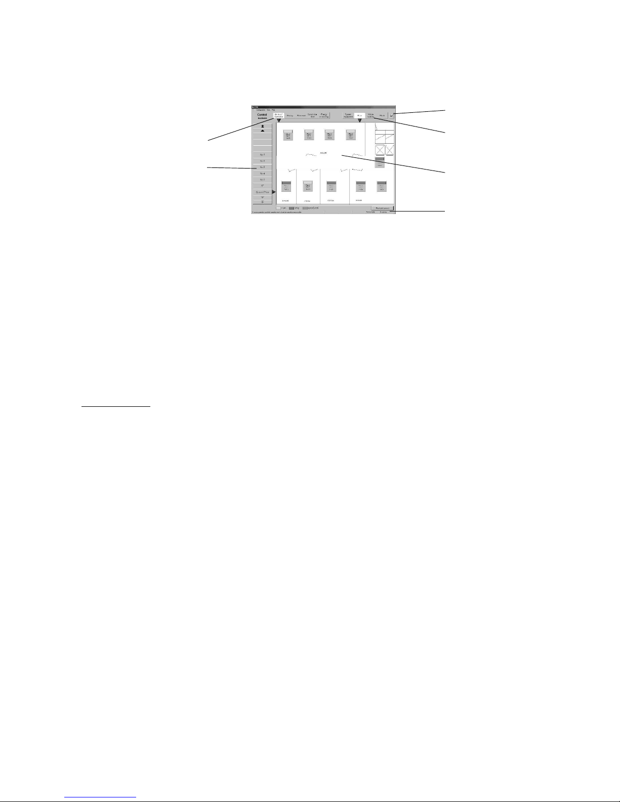
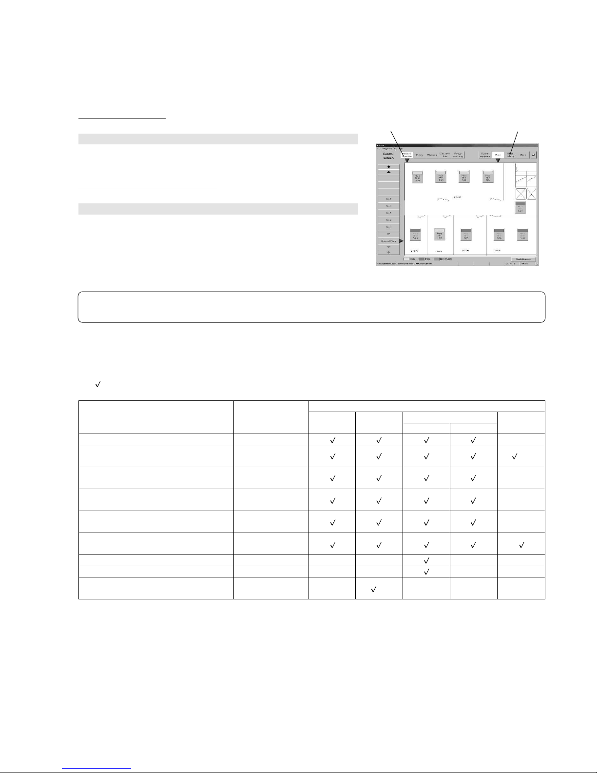
The Management screen consists of the following parts:
Management screen
Display & operation section: Displays and operates the function selected at the function select buttons
Function select buttons: Select the function
Display unit buttons: Select the display unit for each function
Floor switching buttons: Switches the floor
Hard copy button: Prints the currently displayed screen. Printing can be performed while a function is operating
Message bar: Displays operation commands, current time, and system status
There are two system statuses: Serious failure and Minor failure
Serious failure · · · · · · · · Abnormality at IFU, G/W. Indicates that part of the system is not operating normally.
Slight failure · · · · · · · · · · Abnormality in Air conditioning unit. Indicates that part of the system is not operating normally.
3.2 Operations
Mouse operation
The following description assumes that a mouse is used as the pointing device. When using another pointing device, read the
description for that device.
Operation on the screen is the same.
The keyboard can also be used to input characters and numerics.
Move the mouse while viewing the arrow (mouse pointer) on the screen.
Use the left mouse button only.
The following describes the operations:
Click: Pressing and releasing the mouse button once is called “click”.
This operation is used when selecting a button.
Double click: Pressing and releasing the mouse button twice in rapid succession is called “double click”.
Drag: The mouse pointer is moved to an icon and the left mouse button is held down. When the mouse is moved in
this state, the icon moves as if it were being dragged. This operation is called “drag”. The icon can be left at the
new position by releasing the left mouse button.
Keyboard: Primarily used when entering password, characters, or numerics.
Function select buttons
Hard Copy button
Floor switching buttons
Display unit buttons
Display & operation section
Message bar
Page 6
4
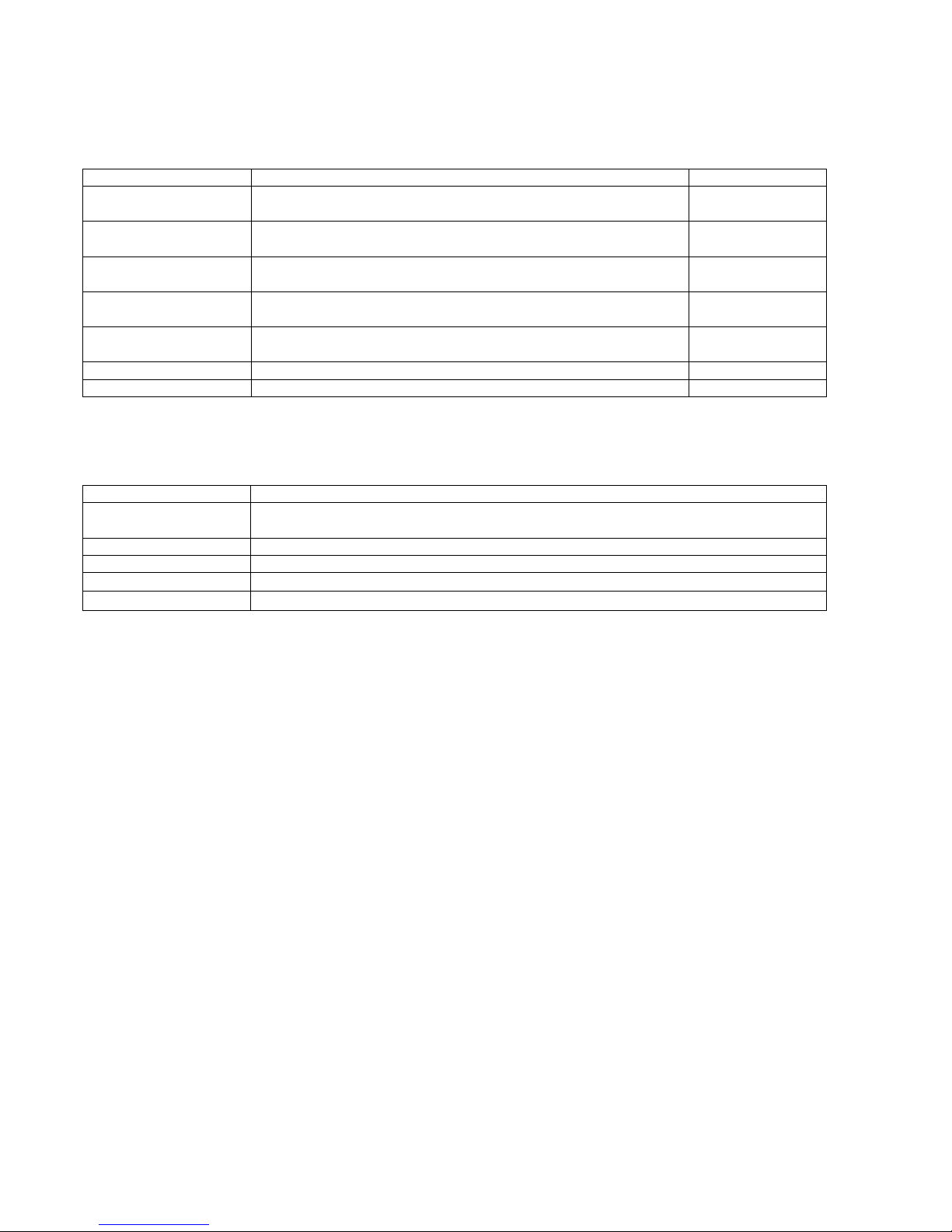
3.3 Functions Table
The MJ-310E has two major functions.
1) Function which monitors the operation status of the air conditioner and controls and sets the air conditioner.
2) Operation function and system initialization and maintenance function.
This section mainly describes function 1).
Function 1) consists of the items shown below. The screen that displays this function is called the “Management screen”.
The following items are necessary when the system configuration was changed, but are not covered in this manual.
Change operation requires a knowledge of system set-up. For the detailed contents and operating instructions, refer to the separate “Site Adjustment manual”.
Name
Air conditioner on/stop
Air conditioner control
Priority specification
History
Cumulative time
Schedule setting
Air-conditioning charge
Function
On/stop operation can be performed in group, floor, block, or whole air
conditioner units. The operating status can also be monitored
Operation (heat/fan/cool/dry) can be switched and the room temperature
can be adjusted in group, floor, block, or whole air conditioner units
Operation can be permitted and prohibited from the local remote
controller in group, floor, block, or whole air conditioner units
The history of abnormalities and operation can be referenced in group,
floor, block, or whole air conditioner units
The air conditioner cumulative operation time can be referenced for each
group
Air conditioner operation can be scheduled for each group
The air-conditioning charge can be monitored for each watt hour meter
Reference
6.1 6.2
6.3
6.3
8.1
8.2
7
9
Name
System configuration set
Charge system set
Charge data maintenance
Operation data monitoring
Remedial apportioning
Function
Performs connected devices, refrigerant system connection, group, operation mode and other
functions settings and block and other settings
Performs various settings for air-conditioning charge calculation
Past charge data can be referenced
Monitors operation data backed-up at IFU
Remedies charge apportioning at WHM failure, etc.
Page 7
5
4. Screen Basic Operation
The function is selected with the function select buttons (top left-hand side of screen) and the operation object is displayed on
the display & operation screen with the display unit buttons (top right of screen).
4.1 Button Selection Method
(1) Select the function
[Procedure]
1) Select the function
Select the function by clicking the function select button of the function to
be displayed and performed.
(2) Select the object to be operated
[Procedure]
1) Select the display unit
Select the display unit by clicking the button of the object unit you want to
display.
4.2 Operation Contents and Function Select Buttons and Display Unit Buttons
This table shows which function display buttons and display unit buttons should be selected when performing an operation.
The symbol indicates that the operation can be performed and the – symbol indicates that the operation cannot be performed.
Note:
- For a detailed description of basic operation, see chapter “6. Normal Operation”.
Control screen
Function select buttons
Display unit buttons
❈1: Other equipment includes IFU, Gateway, system controller, and local remote controller.
❈2: Normal/abnormal display only.
❈3: When Energy monitoring is selected, the air-conditioning charge is displayed even if a display unit button is not selected.
The air-conditioning charge can be displayed in block or watt hour meter units.
Operation
On/off (Run/stop) switching
Operation status (run/stop/abnormality)
check
Detailed setting of operation mode,
temperature, etc.
Operation prohibition setting from local
remote controller
Year schedule and week schedule
setting
Abnormality history and operation
history check
Cumulative time check
Filter sign reset
Energy monitoring
Floor
Display unit buttons (display object)
Function select
button
Monitor/operation
Monitor/operation
Monitor/operation
Monitor/operation
Monitor/operation
History
Cumulative time
Filter reset
Energy
monitoring
Block
—
—
❈3
Group
—
Floor
—
—
—
System
equipment
❈1
—
❈2
—
—
—
—
—
—
Whole
building
—
—
—
Page 8
6
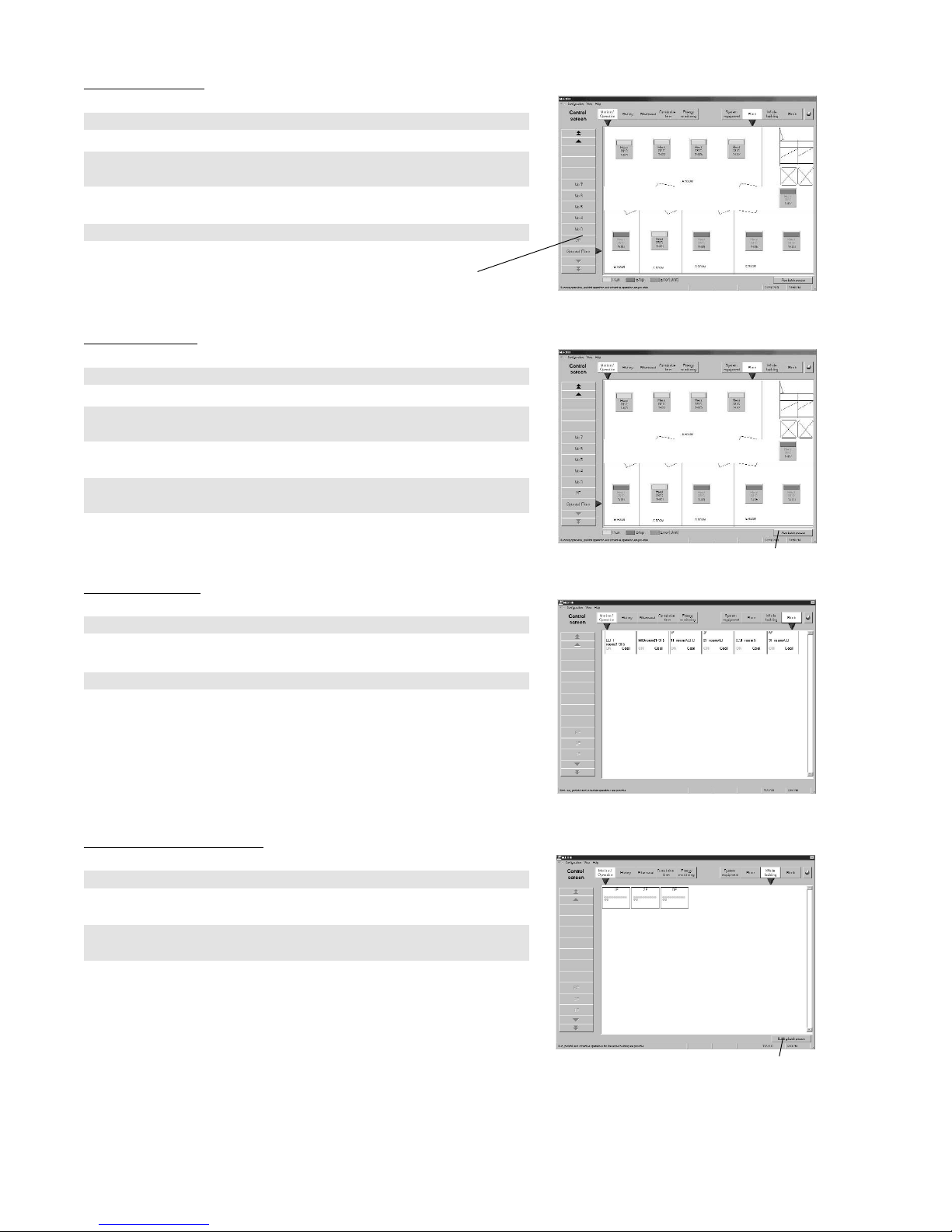
4.3 Display Unit Buttons Operation
(1) Group selection
[Procedure]
1) Click the Floor display unit button
2) Select the object group from the floor switching buttons (left-hand side of
screen)
The selected floor is exhibited on the display & operation screen.
3) Click the object group icon on the displayed floor
(2) Floor selection
[Procedure]
1) Click the Floor display unit button
2) Select the object floor from the floor switching buttons (left-hand side of
screen)
The object floor is exhibited on the display & operation screen
3) Click the Floor batch process button at the bottom right-hand corner of
the screen
(3) Block selection
[Procedure]
1) Click the Block display unit button
All the blocks are exhibited on the display & operation screen.
2) Select the object block from the display & operation screen
(4) Whole building selection
[Procedure]
1) Click the Whole building display unit button
The whole floor is exhibited on the display & operation screen.
2) Click the Building batch process button (bottom right-hand corner
of screen)
Floor screen
Block screen
Whole building screen
Floor batch process button
Building batch process button
Floor screen
Floor switching buttons
Page 9

7
(5) System equipment, IFU, Gateway (G/W) selection
[Procedure]
1) Click the System equipment display unit button
IFU and G/W are exhibited on the display & operation screen.
2) Select G/W of the object system equipment with the G/W switching
button
The system equipment of the selected G/W is displayed on the display &
operation screen
3) Select the object system equipment from the display & operation screen
4.4 Screen Saver Display
When the mouse and keyboard are not touched for a certain length of time, the screen saver starts. (To prevent burning of the
personal computer screen.) The following messages flow across the screen saver screen.
System equipment screen
Maintenance Tip
- Do not set the screen saver at other than the Marquee Display. If set at other than the Marquee Display, the screen saver
will not display the message contents.
Note:
- The “Watt hour meter failure” message is displayed when a message box indicating that a watt hour meter monitor abnormality was detected is displayed. When this message box is not displayed, the screen saver will not display the “Watt
hour meter failure” message.
Gateway switching button
Message contents
MJ-310E
Watt hour meter failure
Serious failure
Serious failure + watt hour meter failure
Slight failure
Slight failure + watt hour meter failure
Contents
No abnormalities in system equipment and air conditioner (When normal)
Abnormality detected at watt hour meter monitor
Abnormality detected at IFU or G/W
Abnormality occurred at IFU or G/W and detected at watt hour meter monitor
Abnormality in air conditioner
Abnormality occurred at air conditioner and detected at watt hour meter monitor
Page 10

8
5. Initialization Before Use
5.1 Schedule Setting
For a description of the schedule setting method, see chapter 7. Schedule Setting.
5.2 Air-conditioning Charge Setting
When the “Energy monitoring” button at the top left-hand side of the Control screen is clicked, the Air-conditioning energy monitoring screen is opened. Air-conditioning energy monitoring is initialized from this screen.
5.2.1 Charge setting
There are three charge settings: Exchange Unit setting, Air-con Charge setting, and Basic Charge setting.
Open the Charge Set screen
[Procedure]
1) Click the Charge set button
Click the Charge set button on the air-conditioning charge screen. The
Charge set screen opens.
(1) Set the Currency unit
[Procedure]
1) Click the Selection of Currency unit button
Click the button in the Charge Set screen. The currency unit set screen
opens. This screen is also displayed when the currency Set screen is
opened.
2) Select the currency unit to be used
Click the option box of the currency unit to be used.
Otherwise, in Etc. colum, set a currency unit (9 characters) and the number of digits to be displayed after the decimal point (0 to 4).
(2) Set the electric use unit price
Set the electric use unit price. One charge system can be selected from daytime/nighttime, weekend, seasonal charge, etc.
[Procedure]
1) Click the Air-con charge button
When the Air-con charge button is selected from the Charge Set screen,
the electric use unit price screen opens.
2) Select the charge system to be used
Set the charge system by clicking the option button at the charge system
you want to use.
3) Select the unit price and applicable time or applicable day of the week
Select the unit price, applicable time, applicable date, or applicable day of
the week in accordance with the set charge system.
Some of the data can also be input from the keyboard.
Currency unit set screen
Electric use unit price set screen
Charge set
Air-conditioning charge screen
Note:
- When the charge function is not available, Air-con Charge is not displayed.
Page 11

9
(3) Set the standard (fixed) charge
Block units and watt hour meter units standard charge (per month) can be set. However, for standard charge in watt hour meter
units, only the watt hour meter unit charge object (K controller, OAprocessing unit, etc.) can be set.
[Procedure]
1) Select the Standard Charge button
When the “Standard Charge” button on the Charge Set screen is clicked,
the standard charge set screen opens.
2) Set the standard charge
Set the standard charge in watt hour meter or block units. For watt hour
standard charge, only charge in watt hour meter units is the object.
Standard charge can be input from the keyboard by clicking with the cursor.
Clicking the standard charge allows the value to be input from the keyboad.
Ending charge setting
[Procedure]
1) Click the OK or Cancel button
At the end of charge setting, click the OK button.
OK: Accepts the changes and returns to the air-conditioning charge
screen.
Cancel: Ignore the changes and returns to the air-conditioning charge
screen.
5.2.2 Settlement-date designation setting
Set the settlement-date designation day
Since the air-conditioning charge is calculated once a month, set the settlement date.
[Procedure]
1) Select settlement-date designation specification
When the “Settlement-date designation” button at the bottom right-hand
side of the screen is clicked, the Settlement-date designation specification
screen opens.
2) Specify the settlement
T o specify the end of month, click End of month. To specify the actual date,
click Manual and select the date by clicking the ▲/▼ buttons.
(Numerical values can also be input from the keyboard.)
3) Select OK or Cancel
Click OK to end settlement-date designation setting.
OK: Accepts the changes and completes settlement-date designa-
tion setting.
Cancel: Ignore the changes and completes settlement-date designa-
tion setting.
Note:
- When an item which must be set is not set, a caution message is displayed. Reset that item.
Settlement-
date designation
specification screen
Note:
- The 29th, 30th, and 31th cannot be set as the settlement-date designation. (However, they can be set as the end of
month.)
Standard charge set screen
Note:
- When there is no WHM connection the watt-hour standard charge cannot be set.
Page 12
10
6. Normal Operation
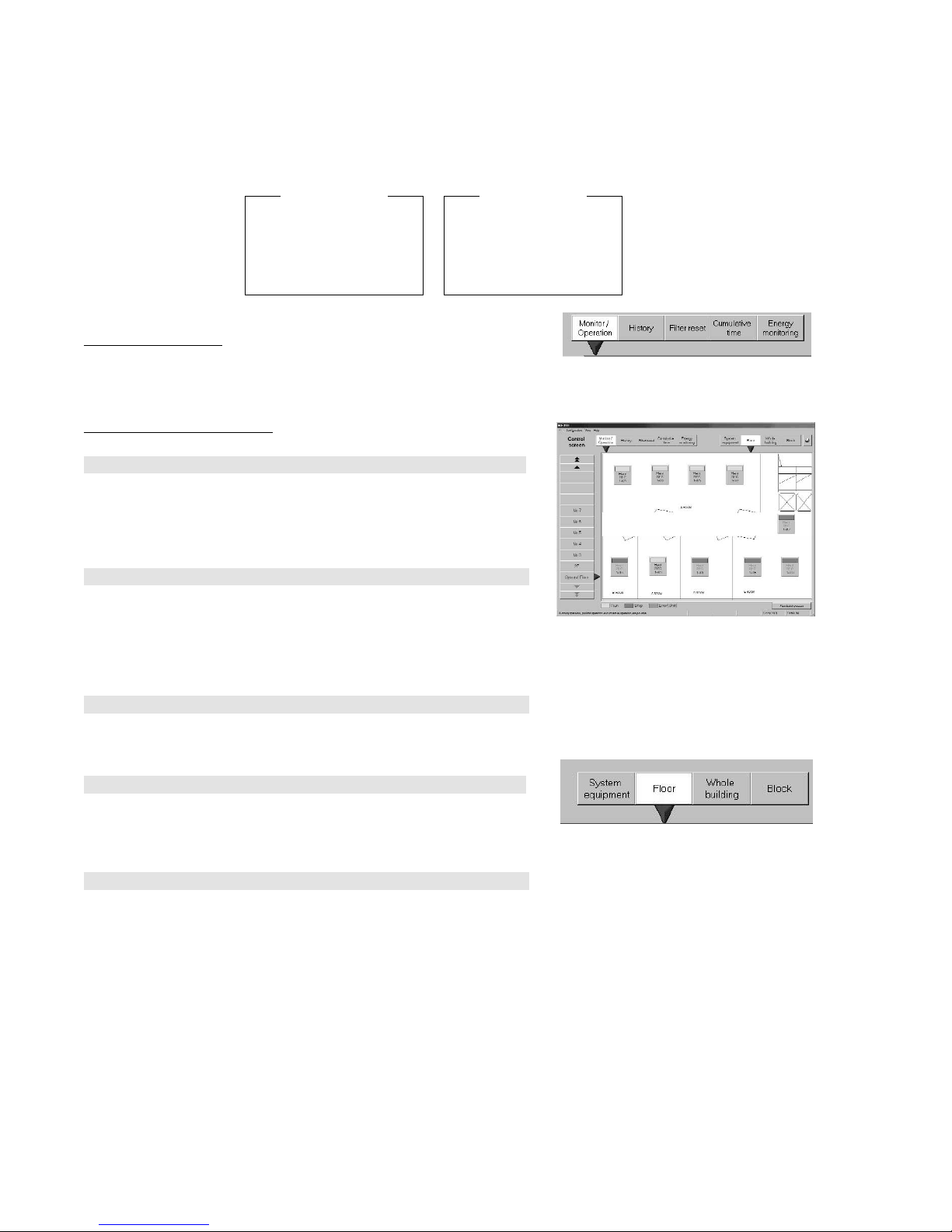
6.0 Monitor/Operation
Perform normal operation from the Management screen.
Display the Management screen by clicking the Monitor/Operation function select button (top left-hand side of screen), then
selecting the operation object from the display unit buttons (top right-hand side of screen). The “Air-conditioning charge display”
is only displayed when there is a charge function.
(1) Select the function
When the Monitor/Operation function select button is clicked, the monitor/
operation screen opens.
(2) Select the operation object
[Procedure]
When group is the object
Click the Floor button in display units.
Select the distribution floor of the object group from the floor switching buttons (left-hand side of screen).
The floor is displayed on the monitor/operation screen.
Click the object group icon on the displayed floor.
When whole floor is the object
Click the Floor button in display units.
Select the object floor from the floor switching buttons (left-hand side of
screen).
The object floor is displayed on the monitor/operation screen.
Click the Floor batch process bottom at the bottom right-hand corner of the
screen.
When block is the object
Click the Block button in display units.
All the blocks are displayed on the monitor/operation screen.
Select the object block from the monitor/operation screen.
When whole building is the object
Click the Whole building button in display units.
Whole building is displayed on the monitor/operation screen.
Click the Building batch process button at the bottom right-hand corner of
the screen.
When system equipment, IFU, or G/W is the object
Click the System equipment button in display units.
IFU, G/W is displayed on the monitor/operation screen.
Select the G/W connected to the object equipment with the G/W select
button (▼).
The system equipment of the selected G/W is displayed in the
monitor/operation screen.
Select the object system equipment from the monitor/operation screen.
Normal operation screen
Function select
- Monitor/Operation
- History
- Filter reset
- Cumulative time
- Energy monitoring
Display units
- System equipment
- Floor
- Whole building
- Block
Display units
Function selection
Page 13

11
6.1 On/Off Operation
Air conditioner On/Off operation is possible.
Block, floor batch, whole building, and other multiple group batch operations are also possible.
Operable objects: Group, floor batch, block, whole building
[Procedure]
1) Select Monitor/Operation
When the Monitor/Operation function select button is clicked, the moni-
tor/operation screen opens.
2) Select the object to be turned on or off
Click the on/of
f object. A menu appears.
3) Select on/stop
If the selected object is currently running, OFF is displayed in the menu
and if the selected object is stopped, ON is displayed in the menu.
When ON or OFF is selected from the menu, operation is switched.
6.2 Operation Status Monitor
The air conditioner operation status can be monitored.
Operable objects: Floor, block, whole building, system equipment
(1) Display the operation status
[Procedure]
1) Select Monitor/Operation
When the Monitor/Operation function select button is clicked, the moni-
tor/operation screen opens.
2) Select the object whose operation status is to be displayed
When the object whose operation status is to be displayed
is clicked, the
current operation status is displayed.
(2) Description of operation status
Floor display screen
Description of floor icons
Operation status display screen: Displays the operation status.
Green: Running
Red: Stopped
Yellow: Abnormal
×
: Local remote controller operation prohibited
Operation mode display screen: Displays the operation mode.
(Example: Auto, Cool, others)
Set temperature display screen: Displays the set temperature.
Group name display screen: Displays the group name. When selected with the mouse cursor, the long name is dis-
played.
Filter sign: Displays Filter in a yellow frame at the center.
(Displayed only when the Filter reset function select button is selected.)
Operation prohibited state: Shows that the system is in the operation prohibited state. (See Notes.)
Outdoor unit abnormal: “ ” is displayed at the top right corner of the group icon.
Subsidiary outdoor unit abnormal: “ ” is displayed at the top right corner of the group icon.
BC controller abnormal: “ ” is displayed at the top right corner of the group icon.
Note:
- When multiple groups are the operation object, if at least one group is on, OFF operation has precedence.
Note:
- For a description of the underlined part, see par. “6.0 (2) Select the operation object” to be operated.
Group icon
Operation status
Operation mode
Set temperature
Group name
Note:
- For a description of the underlined part, see par. “6.0 (2) Select the operation object” to be operated.
Running prohibition state
Page 14
12
G/W abnormal: “ ” is displayed at the top right corner of the group icon.
IFU abnormal: “ ” is displayed at the top right corner of the group icon.
Schedule set: “ ” is displayed at the top left corner of the group icon.
Block & whole building display screen
Displayed in group units in the block frame and floor frame.
(Green): Running (On)
(Red): Stopped (Off)
(Blue): Only running fan unit on
× (Yellow): Abnormal
System equipment display screen
When an equipment is abnormal, × is displayed at the icon of the abnormal equipment.
6.3 Operation Details
Air conditioner operation mode switching, temperature adjustment, and other functions can be monitored and operated.
Objects which can be monitored and operated: Floor, block, whole building
(1) Display the remote control screen
[Procedure]
1) Select Monitor/Operation
When the Monitor/Operation function select button is clicked, the moni-
tor/operation screen opens.
2) Select the object whose remote control screen is to be displayed
Click the object whose remote control screen
is to be displayed.
3) Select properties
When Properties is selected from the menu, the remote control screen
opens.
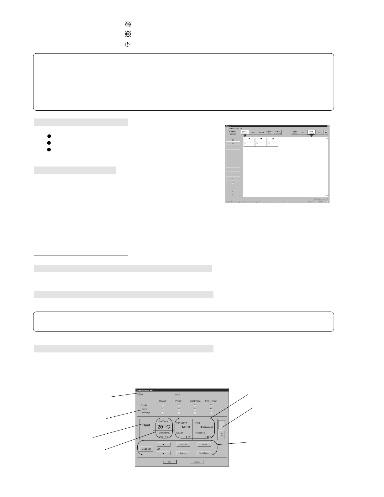
(2) Description of remote control screen
Remote control screen
Note:
- For a description of the underlined part, see par. “6.0 (2) Select the operation object” to be operated.
Remote control
operation prohibit setting
ON/OFF SW
Group and floor names
Operation mode
Temperature display
Fan speed/vane/ventilation
equipment display
Operation section
Note:
- Depending on the characters used, the entire 8 characters of the group name may not be displayed on the icon.
- At stop, the operation mode and set temperature displays are hidden. (Gray characters display)
- When the indoor unit is in the operation prohibited state, the operation mode and set temperature background color
changes to red. In the operation prohibited state, the indoor unit operation state remains stopped, the remote controller
continues to display the operation state, and the operation mode flashes. To reset the operation prohibited state,
change the operation mode.
Some models do not have this display.
Whole building screen
Page 15
13
Group and floor names
- Group name: Displays the group name. (Group object only)
- Floor name: Displays the name of the floor on which the group is distributed.
(For whole building, Whole building is displayed.)
Remote control operation prohibit setting: Displays the operation prohibit setting state of the local remote controller.
ON/OFF: Displays the current operation status by color. (Green: On, Red: Off)
Operation mode: Displays the current operation mode.
Temperature display
- Target set temperature: Displays the target set temperature.
- Indoor temperature: Displays the current indoor temperature.
Fan speed/vane/ventilation equipment display
- Fan speed: Displays the current fan speed.
- Vane: Displays the current wind direction.
- Louver: Displays the current louver status.
- Ventilation equipment: Displays the interlocked ventilation unit status.
Operation section: Performs operation mode, target temperature, and wind setting and other operations.
(3) Remote control screen operation
ON/OFF
Perform ON/OFF switching by clicking the ON/OFF button.
ON (green)/OFF (red) are alternately switched each time the button is clicked.
Operation mode change
Switch the operation mode by clicking the Mode Set button at the operation section.
The operation mode is switched in Fan → Cool → Heat → Dry → Auto → Fan · · · order each time the button is clicked.
For ventilation group, the operation mode is switched in Auto → Heat ex. → By-Pass → Auto · · · order.
(The operation modes that can be changed depends on the setting.)
Set temperature change
Change the set temperature by clicking set temp. adjustment ▲/▼ buttons.
(The range of temperatures that can be changed depends on the operation mode.)
Fan Speed change
Change the wind velocity by clicking the Fan Speed button.
Fan Speed is switched in Lo → Mid 1 → Mid 2 → Hi → Lo · · · order.
For ventilation group, Fan Speed is switched in Lo → Hi → Stop → Lo · · · order.
(The changeable Fan Speed depends on the function setting.)
Vane change
Change the vane by clicking the Vane button.
The vane is switched in Horizontal → Down 60% → Down 80% → Down 100% → Swing → Horizontal · · · order.
(Whether or not there is a Swing and screen direction switching function depends on the function setting.)
*Ventilation group does not have this function.
Louver change
Change the louver by clicking the Louver button.
Louver is switched in On → Off → On · · · order.
(Whether or not there is a Louver switching function depends on the function setting.)
*Ventilation group does not have this function.
Note:
- When the setting is different for each group, the following is displayed by operation from floor batch, whole building
batch, and block:
On/Off: White display
Operation mode: – –
Set temperature: – –
Note:
- The newest information is displayed on the remote control screen only when this remote control screen was displayed.
Page 16

14
Interlocked ventilation group operation
Switch ventilation unit operation by clicking the Ventilation button. (Hi/Lo/Stop)
When ventilation group interlock is set, ON/OFF operation also performs ventilation group Hi/Lo/OFF switching.
(Whether or not there is a ventilation group interlock setting depends on the function setting.)
*Ventilation group does not have this function.
Local remote control operation Prohibit/Permit
When Prohibit On/Off is selected, On/Off operation cannot be performed from the local remote controller.
When Prohibit Mode is selected, the mode cannot be changed from the local remote controller.
When Prohibit Set Temp. is selected, the temperature cannot be changed from the local remote controller.
When Prohibit Filter Reset is selected, filter reset cannot be performed from the local remote controller.
When Unchange is selected, Prohibit/Permit remains in the current state.
(For ventilation group, only On/Off and Filter Reset can be prohibited and permitted.)
Select OK or Cancel
At the end of each setting, click the OK button.
OK: Accepts the changes and returns to the monitor/operation screen.
Cancel: Ignore the changes and returns to the monitor/operation screen.
(4) Other functions
The following are displayed on Floor screen of the monitor/operation screen:
- Long name
- Operation block name
- Charge block name
[Procedure]
1) Select Monitor/Operation
When the Monitor/Operation function select button is clicked, the moni-
tor/operation screen opens.
2) Select floor display
When the Floor display unit button is clicked, the floor display screen
opens.
3) Select group
When the group item of the group whose names are to be displayed is
clicked, a menu appears.
4) Select the name to be displayed
When Long name, Operation block name, or Charge block name is select-
ed from the menu, the names are displayed.
5) Select OK
After checking the names, click the OK button.
Note:
- For floor batch, whole building batch, and block setting, wind velocity, vane, louver, and interlock ventilation operations
cannot be performed. Perform these operations for each group.
- The range over which each setting can be changed depends on the contents set by the indoor unit & ventilation function setting of the system configuration settings. For a detailed description of the setting contents, refer to Site
Adjustment manual section 8.5.9 Indoor Unit and Ventilator Function Settings.
❈ The set contents can be checked by System display. (For the detailed operating instructions, see chapter 10.
System Display.)
- When the wind direction is set to downwards, the indoor unit control may automatically change it to another direction.
Note:
- When the setting is different for each group at floor batch, whole building batch, and block processing, the initial value
is Unchange.
- In the case of K control models, if even one of ON/OFF, mode or set temperature is prohibited, the other settings are
also prohibited. Filter reset can not be prohibited.
Page 17

15
7. Schedule Setting
The operation mode, temperature, wind velocity, and On/stop from the specified time can be set with the schedule setting function. There are two schedules: Weekly schedule and Year schedule. Weekly schedule can be set for each day of the week and
Year schedule can be set in day units. For days set by both schedules, Year schedule has precedence.
The minimum unit that can be set is group.
Operable objects: Group, floor, block, whole building
7.1 Week Schedule Setting
Switch from Management screen to schedule set screen
[Procedure]
1) Select Monitor/Operation
When the Monitor/Operation function select button is clicked, the moni-
tor/operation screen opens.
2) Select the object whose schedule is to be set
Click the object whose schedule is to be set.
When the cursor is moved to Schedule in the displayed menu, the schedule menu is displayed.
3) Select week schedule
When Week schedule is selected from the menu, the Week schedule set
screen opens.
Perform the following operations from the Week schedule set screen.
(1) Schedule setting
[Procedure]
1) Select the day of the week to be set
When the button of the day of the week to be set is clicked, a menu
appears.
2) Select Setting
Select Setting from the menu.
The selected day of the week is displayed in the set day of the week field
at the bottom of the screen.
3) Select the Start time or Stop time
When Start Time or Stop Time is clicked, the Start/Stop set screen opens.
Up to 10 start/stop settings are possible. (Start + Stop <10)
=
4) Set the times, operation prohibit, operation mode, temperature, etc.
Set the times with the ▲/▼ button.
Operation Permit/Prohibit can be set for the local remote controller. ON/OFF
operation, operation mode change, and temperature change can be set.
When a setting does not change, select Unchanging.
Note:
- For a description of the underlined part, see section “6.0 (2) Select the operation object” to be operated.
Note:
- Multiple schedules cannot be set for the same time and a time
between 23:56 and 0:04 cannot be set.
Page 18

The operation mode and temperature can be set by mode and temperature
setting. Switch to a settable operation mode with the Mode button.
The temperature can be changed with the ▲/▼ buttons.
When a setting does not change, select Unchanging.
Use the Delete button to delete a set schedule.
Week schedule can be set up to 10 items/day of the week.
5) Select OK or Cancel
At the end of setting, click the OK button.
The set schedule is displayed at the set day of the week field.
OK: Accepts the changes and returns to the Week schedule set
screen.
Cancel: Ignore the changes and returns to the Week schedule set
screen.
(2) Schedule change
Use this function to change a set schedule.
[Procedure]
1) Select the day of the week to be changed
When the button of the day of the week to be changed is clicked, a menu
appears.
2) Select Setting
Select Setting from the menu.
The selected day of the week is displayed at the set day of the week field.
3) Select the schedule to be changed
When Schedule is clicked, the Start/Stop set screen opens.
For the operating instructions, see (1) Schedule setting.
When only the set time is changed, the change can be made by dragging
Schedule. (10 minutes units)
4) Select OK or Cancel
At the end of setting, click the OK button.
The changed schedule is displayed at the set day of the week field.
OK: Accepts the changes and returns to the week schedule set
screen.
Cancel: Ignore the changes and returns to the week schedule set
screen.
(3) Schedule clearing
[Procedure]
1) Select the day of the week whose schedule is to be cleared
When the button of the day of the week whose schedule is to be cleared is
clicked, a menu appears.
2) Select Clear
Select Clear from the menu.
The clear check screen opens.
3) Select OK or Cancel
After checking the setting, click the OK button.
OK: Clears all the schedules of the selected day of the week and
returns to the Week schedule set screen.
Cancel: Returns to the Week schedule set screen.
16
Note:
- When Unchanging is selected, the temperature and operation mode cannot be changed. Before making any changes,
release Unchanging.
Note:
- When batch schedule setting and schedule check were performed for two or more groups, the setting field of days of the
week with duplicate settings is displayed in cyan.
Note:
- Multiple schedule setting to the same time and a time between 23:56 and 0:04 cannot be set.
Page 19

17
(4) Schedule copy
This function copies the schedule settings of the specified day of the week to another day of the week.
[Procedure]
1) Select the copy from day of the week
When the copy from day of the week button is clicked, a menu appears.
2) Select Copy
Select Copy from the menu.
3) Select the copy to day of the week
When the copy to day of the week is clicked, a menu appears.
4) Select Paste
When Paste is selected from the menu, the schedule of the copy source
day of the week is pasted.
This schedule can also be pasted to other days of the week.
Ending week schedule setting
Select OK or Cancel
At the end of schedule setting and change, click the OK button.
OK: Accepts the changes and returns to the monitor/operation screen.
Cancel: Ignore the changes and returns to the monitor/operation screen.
(When returned to the monitor/operation screen, a schedule mark is displayed at the set group icon.)
7.2 Year Schedule Setting
Switch from Management screen to Schedule set screen
[Procedure]
1) Select the monitor/operation screen
When the Monitor/Operation function select button is clicked, the moni-
tor/operation screen opens.
2) Select the object whose schedule is to be set
Click the object whose schedule is to be set.
When the cursor is moved to Schedule in the displayed menu, a schedule
menu appears.
3) Select Year schedule
When Year schedule is selected from the menu, the Year schedule set
screen opens.
Year schedule is displayed up to 24 months from the current month.
Schedule setting is possible beginning from the current day.
Color of calendar date frame:
White: Not set
Red: Holiday set
Blue: Schedule set
Cyan: Different schedule set for multiple groups
× mark: Past date
Perform the following operations from the Year schedule set screen.
Maintenance Tip
- When only checking the week schedule contents, click Cancel instead of OK at the end of the check.
Note:
- For a description of the underlined part, see par. “6.0 (2) Select the operation object” to be operated.
Page 20

(1) Schedule setting and change
[Procedure]
1) Select the day whose schedule is to be set
When the selected day is clicked, a menu appears.
When Day of the week is clicked, all the days of the week of that month are selected.
2) Select schedule set
Select Setting from the menu.
3) Select the start time or stop time
See pars. 7.1 (1) Schedule setting and 7.1 (2) Schedule change.
4) Select OK or Cancel
At the end of setting, click the OK button.
OK:
Accepts the changes and returns to the Year schedule set screen.
Cancel:
Ignore the changes and returns to the Year schedule set screen.
The set day is displayed in blue on the calendar.
Year schedule can be set up to 20 days/24 months and 10 items/day.
(2) Holiday set/reset
Week schedule for days set as a holiday is invalid.
[Procedure]
1) Select the day to be holiday set/reset
When the day to be holiday set or reset is clicked, a menu appears.
When Day of the week is clicked, all the days of the week of that month
are selected.
2) Select holiday set/reset
Select Holiday set or Holiday reset from the menu.
(3) Schedule clear
When this function is used, all the schedule settings and holiday settings of
the selected day are cleared.
[Procedure]
1) Select the day whose schedule setting and holiday settings are to be cleared
When the day whose schedule and holiday settings are to be cleared is
clicked, a menu appears.
When Day of the week is clicked, the settings for all the days of the week
of that month are cleared.
2) Select schedule clear
Select Clear from the menu.
(4) Schedule copy
This function copies the schedule settings of the specified day to another day.
[Procedure]
1) Select the copy from day
When the copy from day is clicked, a menu appears.
2) Select Copy
Select Copy from the menu.
3) Select the copy to day
When the copy to day is clicked, a menu appears.
4) Select Paste
When Paste is selected from the menu, the schedule of the copy to day is pasted.
This schedule can also be pasted to other days.
18
Note:
- The schedule for today and tomorrow can be set by Year schedule.
- The Year schedule takes priority over the Week schedule.
Page 21

(5) Year schedule check
[Procedure]
1) Select the day to be checked
When the day to be checked is clicked, a menu appears.
2) Select schedule view
When Schedule view is selected from the menu, the Schedule check
screen opens.
The Schedule check screen also has a function that outputs the schedule
to the screen.
Schedule output
[Procedure]
1) Select output
Click the Output button on the Schedule check screen.
(Click Cancel to end the Schedule check screen without outputting the schedule.)
2) Select the output type
Click Printing output or Exporting file.
When Exporting file was selected, input the filename. The save location
can be referenced with the Reference button.
3) Select Output or Cancel
After the contents to be output are set, click the Output button.
Output: Accepts the changes and outputs the schedule and returns to
the preceding screen.
Cancel: Ignore the changes and returns to the preceding screen.
Ending schedule setting
Select OK or Cancel
At the end of schedule setting and change, click the OK button.
OK: Accepts the changes and returns to the monitor/operation screen.
Cancel: Ignore the changes and returns to the monitor/operation screen.
(When returned to the monitor/operation screen, a schedule mark is displayed at the set group icon.)
7.3 Schedule Setting in Group Units
(1) Schedule copy
This function copies the schedule settings of one group to another group.
Operable objects: Floor, block, whole building
[Procedure]
1) Select Monitor/Operation
Click the Monitor/Operation function select button.
2) Click the copy from group
When the cursor is set to Schedule of the menu displayed by clicking the
copy from group, a schedule menu appears.
3) Select Copy
When Copy is selected from the menu, the Copy menu appears.
4) Select the schedule to be copied
Select Week schedule, Year schedule, or Week and Year schedule from the Copy menu.
5) Select the object whose schedule is to be copied
Click the object whose schedule is to be copied.
When the cursor is set to Schedule in the displayed menu, the schedule
menu appears.
19
Note:
- When batch schedule check was performed for two or more groups, [**] is displayed at the days with duplicate settings.
Maintenance Tip
- When only checking the Year schedule, at the end checking, click the Cancel button instead of the OK button.
Page 22

6) Select Paste
When Paste is selected from the menu, the schedule is pasted.
The schedule can also be pasted to other groups, blocks, or floors.
(2) Schedule check
Today’s and yesterday’s schedules of the group can be checked.
Operable objects: Floor, block, whole building
[Procedure]
1) Select Monitor/Operation
When the Monitor/Operation function select button is clicked, the moni-
tor/operation screen opens.
2) Select the object whose schedule is to be checked
Click the object whose schedule is to be checked.
When the cursor is set to Schedule of the displayed menu, a schedule
menu appears.
3) Select Schedule view
When Schedule view is selected from the menu, the schedule check
screen opens.
The schedule check screen also has a function that outputs the schedule to the screen.
Schedule output
[Procedure]
1) Select Output
Click the Output button on the schedule check screen.
(Click the Cancel button to end the schedule check screen without outputting the schedule.)
2) Select the output type
Click Printing output or File exporting.
For File exporting, input the filename. The save location can also be referenced by Reference button.
3) Select Output or Cancel
When the contents to be output are set, click the Output button.
Output: Accepts the changes and outputs the schedule and returns to
the preceding screen.
Cancel: Ignore the changes and returns to the preceding screen.
20
Note:
- For a description of the underlined part, see par. “6.0 (2) Select the operation object” to be operated.
Note:
- For a description of the underlined part, see par. “6.0 (2) Select the opration object” to be operated.
Note:
- When batch schedule check was performed for two or more groups, [**] is displayed at the days with duplicate settings.
Page 23

21
8. Maintenance Operation
8.1 Abnormality History and Operation History
There are two kinds of history: Abnormality history and Operation history.
- Abnormality history: Displays abnormalities that occurred in the past. (WHM abnormality history is not recorded.
)
- Operation history: Displays the operations (start, stop, etc.) performed in the past.
(1) Switch from Management screen to history screen
[Procedure]
1) Select History
Click the History function select button.
2) Select the object whose history is to be displayed
When the object whose history is to be displayed
is clicked, the History
screen opens.
Perform the following operations from the History screen.
(2) Description of History screens
Abnormality history
The Abnormality History screen displays air conditioner failures, transmission failures, and other abnormalities in the order in which they occurred.
Up to 1000 items can be displayed. When the number of items exceeds
1000, the items are deleted in ascending order.
Occurrence time: Displays the time the abnormality occurred.
Recovery time: Displays the time the abnormality recovered. Blank
indicates that the abnormality is still in effect.
Origin address: Displays the G/W No. and address of the equipment at
which the abnormality occurred.
Occurrence point:Displays the occurrence floor at the left and the group
or equipment name at the right.
Contents: Displays the error code and its description.
Operation history
The Operation history screen displays the operations performed at the air
conditioner. Up to 10,000 items can be displayed. When the number of
items exceeds 10,000, the items are sequentially deleted in ascending
order.
Operation time: Displays the time the operation was performed.
Controller: Displays the equipment that issued the operation com-
mand.
Object address: Displays the controller G/W No. and address.
Operation point: Displays the occurrence floor at the left and the group or
equipment name at the right.
Contents: Displays the contents of the operation that was per-
formed.
(3) History screen operation
The Abnormality History and Operation History screen displays can be
switched and updated.
[Procedure]
History display switching
When the Abnormality history button is clicked, the display switches to the
Abnormality History screen and when the Operation history button is
clicked, the display switches to the Operation History screen.
Display updating
When Update of display button is clicked, the display is updated to the current history. The updated time is displayed at Display Time.
Note:
- For a description of the underlined part, see par. “6.0 (2) Select the operation object” to be operated.
Abnormality History screen
Operation History screen
Page 24

(4) History search
This function searches the histories based on the set conditions.
There are the following search items. The search conditions can be set by combining these items.
Abnormality history search
1) Search from abnormality occurrence date
Specifies the occurrence date.
2) Search from abnormality recovery date
Specifies the recovery date.
3) Search from abnormality occurrence point
Specifies IFU, G/W and unit.
4) Search from error code
Specifies the error code that caused the abnormality.
Operation history search
1) Search from operated date
Specifies the operated date.
2) Search from controller
Specifies the controller.
3) Search from operated group
Specifies G/W and group No.
[Procedure]
1) Select Search
When the Search button is clicked, a search screen opens.
2) Input the search item
Specify the search condition at the search item check box. Specify the
object with the Option button.
Numerics can be input by clicking the ▲/▼ buttons at the right-hand side
of the numeric part or by clicking the numeric part. They can also be input
from the keyboard.
Search conditions can also be combined by selecting multiple items.
3) Select Find or Cancel
After setting the search conditions, click the Find button.
(If there is no history that meets the set conditions, nothing is displayed.)
Find: Displays, on the history screen, histories that meet the search
conditions.
Cancel: Returns to the history screen.
(5) History delete
Deletes the specified range of histories from START to END.
[Procedure]
1) Select Delete
When the Delete button is clicked, the Delete screen opens.
2) Input the delete start date
Set the START date with the ▲/▼ buttons. When the numeric part is
clicked, the date can also be input from the keyboard.
3) Input the delete end date
Set the END date with the ▲/▼ buttons. When the numeric part is
clicked, the date can also be input from the keyboard.
4) Select Delete or Cancel
After setting the range of histories to be deleted, click the Delete button.
Delete: Deletes the histories within the specified range and returns to
the history screen.
Cancel: Returns to the history screen without deleting the histories.
22
Note:
- Once deleted, histories cannot be recovered.
Page 25

(6) History output
Outputs daily or monthly history.
The output type can be selected from printing output and file output (text format). (Search results history cannot be output.)
[Procedure]
1) Select Daily or Monthly
When the Daily or Monthly button is clicked, the Output History screen
opens.
2) Input the date to be printed
Set the date with the ▲/▼ buttons at the right-hand side of the numeric
part.
When the numeric part is clicked, the date can also be input from the keyboard. At the end of input, click the Output button. (Click the Cancel button to stop output.)
3) Select printing output or file output
For printing output, click the Printing output option button and for file out-
put, click the Exporting file option button. For file output, input the filename. The save location can be referenced with the Reference button.
4) Select Output or Cancel
When the Output button is clicked, the histories generated within the input
range are output.
Output: Outputs the histories generated within the specified range and
returns to the history screen.
Cancel: Returns to the history screen without outputting the histories.
8.2 Cumulative Time Monitor
(1) Switch from Management screen to cumulative time monitor
[Procedure]
1) Select Cumulative time
When the Cumulative time function select button is clicked, the cumulative
time monitor screen opens. Select the target floor with the floor switching
buttons.
(2) Description of cumulative time monitor
The cumulative time monitor displays Group Address - Group Name Cumulative Time, from left to right.
The cumulative time unit is “hours”.
(3) Cumulative time monitor operation
[Procedure]
1) Select Update of Display.
When the Update of display button is clicked, the cumulative time is updat-
ed to the current cumulative time. The updated time is displayed next to
Display Time at the right-hand side of the screen.
(4) Cumulative time clear
[Procedure]
1) Select the group whose cumulative time is to be reset
When the group to be clear is clicked on the screen, that group changes
to the selected blue color. When that group is clicked again, it is released.
All the groups can be selected with the All select button.
All selections can be released with the All release button.
2) Select Cleared
When the Clear button is clicked, the cumulative time of the selected
group is cleared.
(5) Cumulative time output
This function outputs the cumulative time screen. The output type can be selected from printing output or file output (text format).
23
Note:
- Once cleared, cumulative time cannot
be recovered.
Page 26

24
[Procedure]
1) Select Output
When the Output button is clicked, the cumulative time output screen
opens.
2) Select printing output or file output
For printing output, click the Printing output option button and for file out-
put, click the Exporting file option button. For file output, input the filename. The save location can be referenced with the Reference button.
3) Select Output or Cancel
When the Output button is clicked, all the cumulative times of the dis-
played floor are output.
Output: Outputs the displayed cumulative time screen and returns to
the preceding screen.
Cancel: Returns to the preceding screen without outputting the cumu-
lative time screen.
8.3 Filter Reset Operation
(1) Switch from Management screen to filter reset screen
[Procedure]
1) Select filter reset
When the Filter reset function select button is clicked, the filter reset
screen opens.
Select the target floor with the floor switching buttons.
(2) Description of filter reset screen
The filter sign is displayed in a yellow frame at the center of the group icon.
(3) Filter reset
[Procedure]
1) Select a group displaying the filter sign
When a group displaying the filter sign is clicked, the filter reset screen
opens.
To reset the whole floor, press the Floor batch process button.
2) Select OK or Cancel
When the OK button is clicked, the filter sign is reset.
OK: Resets the filter sign and returns to the filter reset screen.
Cancel: Returns to the filter reset screen.
8.4 Abnormality Occurrence
8.4.1 Abnormality Display
Equipment at which abnormalities can be detected: Indoor unit, ventilation unit, outdoor unit, G/W, IFU, remote controller, group
remote controller, SC
(1) Display when abnormality occurs
Indoor unit abnormality
The color of the group icon status display screen changes to yellow.
For whole building display, × is displayed in yellow at groups. When there
is an abnormal unit in a block, the word “error” appears in orange at the
block status. Also, “Slight failure” is displayed on the message bar at the
bottom of the screen.
Maintenance Tip
- Always perform filter maintenance (cleaning, replacement, etc.) of the actual equipment before using this function to reset
the filter sign.
Filter sign
Page 27

25
Outdoor unit abnormality
× OC is displayed at the group icon of the outdoor unit at which the abnormality occurred and the equipment connected to it. In the system equipment screen, × is displayed at the icon of the outdoor unit at which the
abnormality occurred.
IFU abnormality
× IFU is displayed at the group icon of the equipment (all kinds) connected
to the abnormal IFU. In the system equipment screen, × is displayed at the
IFU icon. Also, Serious failure is displayed on the message bar at the bottom of the screen.
G/W abnormality
× G/W is displayed at the group icon of the equipment connected to the
abnormal G/W. In the system equipment screen, × is displayed at the icon
of the abnormal G/W.
Also, Serious failure is displayed on the message bar at the bottom of the
screen.
8.4.2 Abnormality Reset Operation
The abnormality reset operation can send an abnormality reset command to an abnormal unit.
However, when the unit abnormality is not actually cleared, the abnormality cannot be reset.
Equipment which can be reset: Indoor unit, outdoor unit
(1) Abnormality reset method
[Procedure]
1) Select Monitor/Operation
When the Monitor/Operation function select button is clicked, the moni-
tor/operation screen opens.
2) Select the object to be reset
When the object to be reset
is clicked, the menu screen opens.
3) Click the Error Reset
When the Error reset is clicked, a check screen is displayed.
4) Select OK or Cancel
When the OK button is clicked, the abnormality reset operation is per-
formed.
OK: Performs the abnormality reset operation and returns to the
monitor/operation screen.
Cancel: Returns to the monitor/operation screen without performing the
abnormality reset operation.
8.4.3 Corrective Action When Watt Hour Meter Abnormal
The watt hour meter abnormality function detects connected watt hour meter failure and transmission line breakage at the watt
hour meter monitor.
(Since the abnormality occurs between the previous monitor time and the current monitor time, it is not a real-time abnormality.)
(1) Display method when abnormality detected
When a watt hour meter abnormality is detected, the message box shown at
the right is displayed.
(2) Abnormality reset method
Click OK in the message box and restore operation and inspect and repair the
watt hour meter.
Note:
- IFU, Gateway, remote controller, and system controller abnormalities cannot be reset.
Note:
- For a description of the underlined part, see par. “6.0 (2) Select the
operation object” to be operated.
Note:
- Other operations cannot be performed while this message is being
displayed.
OK button
Page 28

26
8.5 Fire Alarm Stop
(1) Start of fire alarm stop
When the fire alarm stop signal is input, the Fire alarm stop operating
message box is displayed. The system sends stop operation and operation prohibition commands to all the indoor units and disables operation
from the local remote controllers. It also stops the schedule function.
Man-machine operation is also impossible while this message box is displayed. However, when the message box is cleared, operation is enabled.
(2) End of fire alarm stop
When the fire alarm stop signal is reset, the Fire alarm stop operating message box is cleared. An operation prohibition reset
command is sent to all the indoor units and the operation prohibition status returns to its state before the fire alarm stop operation. The schedule function is restarted and schedule operation groups return to the status in which they were before the
fire alarm stop operation.
Note:
- When the personal computer, I/O board, IFU, GateWay, etc. is abnormal or the power is OFF, the fire alarm function may
not operate.
- During fire alarm stop input, Fire Alarm is displayed on the message bar.
Fire alarm stop message
Note:
- The unit operation status does not return to the status before the fire alarm stop operation even if fire alarm stop is
reset. Perform running operation from the local remote controller, by man-machine operation, etc.
Page 29

27
9. Air-Conditioning Energy Monitor
9.1 Charge Display Function
When the Energy monitoring button at the top left-hand side of the Management screen is clicked, this screen opens.
There are two types of monitoring screens: With WHM connection and Without WHM connection.
Functions table
[With WHM connection]
Air-conditioning energy monitoring screen
[Without WHM connection]
Air-conditioning energy monitoring screen
[Description of displays and buttons]
(1) Block names
Displays the block units air-conditioning charges for up to three preceding months.
(2) Watt hour meter
Displays the watt hour units air-conditioning charge for up to three preceding months.
(3) Apportioned electric power
Displays the Apportioned electric power for each unit.
(4) Apportioning charge
Displays the monthly air-conditioning charge: (electric use unit price + standard charge) for each unit.
(5) Apportioning total
Displays the proportional division electric power and proportional division charge.
Individual output
Apportioned electric
power
Block names or
Watt hour meter
Apportioning total
Whole term day specification
Apportioned charge
Recalculation
Note:
- This function cannot be used if the Use charge function is not selected by user setting. (The Energy monitoring button is
not displayed either.)
- Block air-conditioning charge does not include the electric amount of the watt hour meter units K controller, OA processing unit, etc.
- The Without WHM connection air-conditioning charge only covers the refrigerant usage amount of the M-NET indoor unit.
The electric amount and charge are temporarily calculated from the indoor unit capacity and operation amount, and can-
not be used as is. They are also different from the With WHM connection air-conditioning charge.
Calculated charge
display
Percentage accuracy
display
Page 30

28
(6) Individual specification
Specifies an individual object and calculates and outputs the air-conditioning charge.
1) Date specification
Specifies the date and calculates and outputs the air-conditioning charge for the selected block.
2) Individual output
Calculates and outputs the air-conditioning charge for the selected block.
(7) Whole building object
Sets, calculates and outputs the air-conditioning charge for the whole building.
1) Whole term day specification
Specifies the term day and calculates and outputs the air-conditioning charge for all blocks, or all watt hour meters.
2) Whole building output
Specifies the term day and calculates and outputs the air-conditioning charge for all blocks and all watt hour meters.
3) Settlement date designation
Specifies the air-conditioning charge settlement date designation.
4) Electric power under stop
Displays and outputs the electric power under stop.
5) Charge set
Calls the Air-conditioning energy monitoring basic set screen.
(8) Recalculation
Recalculates the air-conditioning charges.
(9) Calculated charge display
Displays and outputs the billing electric amount and calculated air-conditioning charge.
(10) Percentage accuracy display
Displays and outputs the billing electric amount and percentage accuracy.
9.2 Block and Watt Hour Meter Air-conditioning Energy Monitor Display
(1) Select the display object
1) Select the display object.
With WHM connection
Select the display object with the Charge block or Watt hour meter button at the top left-hand side of the screen.
Without WHM connection
Select the display type with the Calculated charge display or Percentage
accuracy display button at the top left-hand side of the screen. The display object is only Block.
(2) Display color
Characters color
Black characters: Normal
Red characters: Abnormal
Blue characters: Maintenance
9.3 Air-conditioning Charge Output
(1) Set the automatic printing function
[Procedure]
1) Select Settlement date designation
When the Settlement data designation button is clicked, the settlement
of date designation screen opens.
2) Specify the settlement date
When specifying the end of month, click End of month.
When specifying other than the end of month, click Manual.
Set the date by clicking the ▲/▼ buttons.
(The date can also be input from the keyboard.)
Note:
- The electric amount, charge, etc. displays are the values with the
undisplayed digits raised to the next higher digit. The total is the
total of the displayed values.
- When the maintenance function was used to change and recalculate the Apportioned electric power, the characters turn to blue.
❈ - For a description of the maintenance function, refer to Field
Adjustment manual section “9.2 Charge Data Maintenance”.
- For a description of the recalculation function, see section 9.6
Recalculate the air-conditioning charge.
Page 31

29
(2) Description of functions
1) Individual air-conditioning charge output
When the Air-conditioning energy monitoring screen is block display, selects and outputs the unit block and when the Air-con-
ditioning energy monitoring screen is watt hour meter display, selects and outputs the unit watt hour meter.
Date specification: Specifies the term day and calculates and outputs the air-conditioning charge.
Individual output: Selects 1 month before, 2 months before, or 3 months before and outputs the air-conditioning charge
in month units.
2) Whole building air-conditioning charge output
Specifies all blocks, all watt hour meters, or all blocks and all watt hour meters and outputs the air-conditioning charge.
Whole term day specification: Specifies the term day and calculates and outputs the air-conditioning charge.
Individual output: Selects 1 month before, 2 months before, or 3 months before and calculates and outputs the
air-conditioning charge in month units.
(3) Individual air-conditioning charge output
Set the Air-conditioning energy monitoring screen to
- Output in block units: Charge Block display
- Output in watt hour meter units: Watt hour display.
(For a description of the setting method, see par. “9.2 Block and Watt Hour Meter Charge Display”.)
Output the air-conditioning charge by specifying the term day
[Procedure]
1) Select date specification
When the Date specification button of the Individual specification buttons
at the right-hand side of the screen is clicked, the date specification set
screen opens.
2) Select the object to be output
Click the object box and click the block or watt hour meter to be output.
3) Specify the date
Specify the date by clicking the ▲/▼ buttons.
4) Select OK or Cancel
After specifying the output object and date, click the OK button.
OK: Accepts the changes and advances to the next set screen.
Cancel: Ignore the changes and returns to the Air-conditioning energy
monitoring screen.
5) Check the calculation contents
The setting above displays the object, date, proportional division electric
power, and proportional division charge. Check the display contents.
6) Select Output or Cancel
After checking the output contents, click the Output button.
Output: Accepts the changes and advances to the Output type set
screen.
Cancel: Ignore the changes and returns to the air-conditioning charge
screen.
The above ends date specification calculation and output setting.
Note:
- The air-conditioning charge for the current month is printed at the day after the settlement date (04:20 and thereafter).
Maintenance Tip
- To use the air-conditioning charge automatic printing function, set Printer setting to Printer and Air-conditioning charge
automatic printing to Automatic printing.
- Select Air-conditioning charge print process from Standard printing, Print itemized account for each unit, and Print itemized within a time. (For more information, refer to Field Adjustment manual section “8.3 User Definition Setting”.)
Maintenance Tip
- When using this function to print, set Printer setting to Printer by user setting.
Page 32

30
Output the air-conditioning charge by specifying last month, 2 months before, or 3 months before.
[Procedure]
1) Select individual specification
When the Individual output button of the Individual specification buttons at
the right-hand side of the screen is clicked, the individual output set screen
opens.
2) Select the output object
Click the object box, and click the block or watt hour meter to be output.
3) Specify the output month
Specify the term by clicking the month to be output.
4) Select Output or Cancel
After setting the output object and month, click the Output button.
Output: Accepts the changes and advances to the Output type set
screen.
Cancel: Ignore the changes and returns to the Air-conditioning energy
monitoring screen.
The above ends individual output setting.
(4) Output whole building air-conditioning charge
Output the air-conditioning charge by specifying the term
[Procedure]
1) Select Whole term day specification
When the Whole term day specification button of the Whole building object
buttons at the right-hand side of the screen is clicked, the Whole term day
specification set screen opens.
2) Select the output object (Calculation item)
Click All Blocks or All Watt hour meters.
3) Specify the term day
Specify the term day by clicking the ▲/▼ buttons.
4) Select OK or Cancel
After specifying the output object and term day, click the OK button.
OK: Accepts the changes and advances to the next set screen.
Cancel: Ignore the changes and returns to the Air-conditioning energy
monitoring screen.
5) Check the Date specification energy monitoring calculation result
The setting above displays the calculation item, term day, Apportioned con-
sumption amount, and Apportioned charge. Check the display contents.
6) Select Output or Cancel
After checking the output contents, click the Output button.
Output: Accepts the changes and advances to the Output type set
screen.
Cancel: Ignore the changes and returns to the Air-conditioning energy
monitoring screen.
The above ends whole term day specification calculation and output setting.
Note:
- Underlined Output type set screen is used in common with other functions.
For more information, see par. “9.3 (5) Output type Setting”.
- For Without WHM connection, the output object is only All blocks.
Note:
- The underlined Output type set screen is used in common with other functions.
- For more information, see par. “9.3 (5) Output type Setting”.
Page 33

31
Output the air-conditioning charge by specifying last month, 2 months before, or 3 months before
[Procedure]
1) Select Whole building output
When the Whole building output button of the Whole building object but-
tons at the right-hand side of the screen is clicked, the Individual output set
screen opens.
2) Select the output object watt hour
Click All blocks, All watt-hour meters, or All blocks and all watt hour meters.
3) Specify the output month
Specify the date by clicking the output month.
4) Select Output or Cancel
After specifying the output object and month, click the Output button.
Output: Accepts the setting and advances to the Output type set
screen.
Cancel: Rejects the setting and returns to the Air-conditioning energy
monitoring screen.
The above ends whole building output setting.
(5) Output type Setting
The following operations are necessary at output functions (3) and (4) above.
[Procedure]
1) Select the output type
The output type is displayed. To print, click Printing output and to output a
file, click Exporting file and input the filename.
2) Select Output or Cancel
After selecting the output type, click the Output button.
Output: Performs output processing and ends this function.
Cancel: Ignore the changes and returns to the Air-conditioning energy
monitoring screen.
9.4 Under Stop Charge
“Under stop charge” is the standby use electric power charge by watt hour meter used by the outdoor unit crankcase heater.
Output and display the electric power amount and charge under stop
[Procedure]
1) Select Electric power under stop
When the Electric power under stop button of the Whole building object
buttons at the right-hand side of the screen is clicked, the Electric power
under stop screen opens.
2) Check the display contents
The electric power under stop for up to three months is displayed.
3) Select Output or Cancel
After specifying the output object and date, click the Output button.
Output: Accepts the changes and advances to the Output type set
screen.
Cancel: Ignore the changes and returns to the Air-conditioning energy
monitoring screen.
The above ends electric power under stop output setting.
Note:
- Underlined Output type set screen is used in common with other functions. For more information, see par. “9.3 (5) Output
type setting”.
- For Without WHM connection, the output object is only All blocks.
Note:
- The underlined Output type set screen is used in common with other functions. For more information, see par. “9.3 (5)
Output type Setting”.
- For Without WHM connection, the output object is only All blocks.
Page 34

9.5 Air-conditioning Charge Basic Setting
Set the air-conditioning charge basic setting
[Procedure]
1) Select air-conditioning charge basic setting
When the Charge set button at the button right-hand side of the screen is
clicked, the Charge set screen opens.
Basic setting contents
- Currency Unit: Current unit setting
- Air-con charge: Within a time yes/no, within a time setting, Electric
use unit price, holiday setting, etc.
- Standard charge: Block and watt hour meter standard charge setting
2) Select the setting function
When one of the three buttons above at the top left-hand side of the
screen is clicked, the respective set screen is displayed.
3) Select OK or Cancel
At the end of basic setting, click the OK button.
OK: Accepts the changes and returns to the Air-conditioning ener-
gy monitoring screen.
Cancel: Ignore the changes and returns to the Air-conditioning energy
monitoring screen.
9.6 Recalculate the Air-conditioning Charge
Recalculate the air-conditioning charge
This function recalculates the air-conditioning charge for one month based on
the Apportioning electric power already calculated.
When the maintenance function was used to correct the Apportioning electric
power, use this function to recalculate the air-conditioning charge.
[Procedure]
1) Select recalculation
When the Recalculate button at the bottom right-hand side of the screen
is clicked, the recalculation screen opens.
2) Select the recalculation month
Click the month to be recalculated.
3) Select OK or Cancel
After specifying the recalculation month, click the OK button.
OK: Accepts the setting and recalculates the air-conditioning
charge for the specified month and reflects the recalculated
charge at the Air-conditioning energy monitoring screen.
Cancel: Rejects the setting and returns to the Air-conditioning energy
monitoring screen.
32
Note:
- For a detailed description of the setting method, etc. of this function, see section 5.2.1 Charge setting.
- For WHM connection, the Standard charge setting function cannot be used.
Note:
- For a description of the Apportioning electric power correction method, refer to Site Adjustment manual section “9.2
Maintenance of charge date”.
Note:
- The underlined Output type set screen is used in common with other functions.
For more information, see par. “9.3 (5) Output type Setting”.
- For Without WHM connection, this function cannot be used.
Maintenance Tip
- Use this function (under stop charge) only when Make crankcase heater portion common expense (make under stop
charge) was selected by charge setting Charge proportional division method selection.
(For a description of Charge proportional division method selection, refer to Site Adjustment manual section “8.7 Charge
System Setting”.)
❈Electric power under stop
Outdoor unit electric power under stop = outdoor unit crankcase heater capacity(W) × 24 hours
Page 35

33
10. System Display
The current system configuration and charge system can be displayed.
This function checks the system status, but cannot change it.
10.1 System configuration display
For the units corresponding to the icons displayed on each set screen, see
the table at the right.
Select System configuration view in the View menu bar
The system configuration screen appears.
(1) GateWay unit configuration
Select System configuration view in the View menu (menu bar).
Displays the number of set G/W and the unit configuration of each G/W.
Select the G/W to be displayed by clicking the ▲/▼ buttons
The numeric in the frame is the address. The displayed icons indicates that
the units are connected to the selected G/W.
The screen can also be printed with the print button.
After checking the set contents, click the Next button
Next: Advances to the next screen.
Exit: Returns to the Management screen.
(2) Refrigerant system setting display
Displays the refrigerant system of each outdoor unit at each G/W.
Indicates that units in the same row are connected to the OC at the left-hand side of the screen.
Select the G/W to be displayed by clicking the ▲/▼ buttons
The screen can also be printed with the print button.
After checking the set contents, click the Next button
Next: Advances to next screen.
Exit: Returns to Management screen.
Back: Returns to last screen.
Note:
- When changing the system configuration, refer to Site Adjustment
manual section “8.5 System Configuration Setting”.
Icon
IC
KIC
LC
FU
OC
BC
OS
RC
GR
SR
LR
TR
AN
SC
Name
Indoor unit
K control indoor unit (A control)
Lossnay
OA Processing unit
Outdoor unit
BC controller
Subsidiary outdoor unit
Remote controller
Group remote controller
System remote controller
Lossnay remote controller
Centralized remote controller
On/Off controller
System controllers
Set G/W number
Print button
G/W No.
Set G/W number
Print button
G/W No.
Connected unit
Page 36

34
(3) Group setting display
Displays the group setting of each indoor unit on each floor.
Indicates that units on the same group No. row at the left-hand side of the screen are connected to the same group.
Select the display floor by clicking the ▲/▼ buttons at the right of the floor name
When G/W is selected using the ▲/▼ buttons next to G/W No., the units of each G/W are displayed. The screen can also be
printed with the print button.
After checking the set contents, click the Next button
Next: Advances to next screen.
Exit: Returns to Management screen.
Back: Returns to last screen.
(4) Ventilation group setting display
Displays the ventilation group setting of each indoor unit for each G/W.
Indicates that the units on the same row as the group No. at the left-hand side of the screen are connected to the same group.
The displayed floor can be switched by clicking the s/t buttons at the right of the floor name
When the G/W is selected by clicking the ▲/▼ buttons next to G/W No., the unit of each G/W is displayed. The screen can also
be printed with the print button.
After checking the set contents, click the Next button
Next: Advances to next screen.
Exit: Returns to Management screen.
Back: Returns to last screen.
Print button
Floor name
G/W No.
Print button
Floor name
G/W No.
Page 37

35
(5) Functional set up an indoor unit and vertilation display
Displays the function settings of each indoor unit group of each floor. The left-hand end is the group No., and indicates whether
or not each function is available on the same row. The functions are arranged from left to right in mode (Fan, Cool, Dry, Heat,
Auto), Humiditier louver, vane, swing, Fan speed, and ventilation equipment order.
Select the display floor by clicking the ▲/▼ buttons next at the right of the floor name
The screen can be printed with the Print button.
After checking the set contents, click the Next button
Next: Advances to next screen.
Exit: Returns to Management screen.
Back: Returns to last screen.
(6) Block setting display
Displays the block setting status of each indoor unit group at each floor. Block No. is displayed at each block set group.
Select the floor to be displayed by clicking the ▲/▼ button next to the floor name
This screen can also be printed with the Print button.
After checking the set contents, click the Exit button
Exit: Returns to Management screen.
Back: Returns to last screen.
Floor name
Floor name
Print button
Print button
Note:
- When the “Block name” button is clicked, the set block name can be checked.
Page 38

36
10.2 Charge system display
See the table at the right for the units corresponding to the icons displayed
on the setting screens.
Select Energy monitoring view in the View menu bar
The charge system screen is displayed.
(1) Watt-hour meter name and maximum integrated value display
Displays the name and maximum integrated value of the connected and set watt-hour meters.
This screen can also be printed with the Print button.
After checking the set contents, click the Exit button
Next: Advances to next screen.
Exit: Returns to Management screen.
(2) Division mode display
Displays the division mode setting state.
This screen can also be printed with the Print button.
After checking the set contents, click the Next button
Next: Advances to next screen.
Back: Returns to last screen.
Exit: Returns to Management screen.
Note:
- When changing the charge system, refer to Site Adjustment manual section “8.7 Charge System Setting”
- Some charge system display screens may not be displayed,
depending on the setting mode.
Icon
IC
LC
FU
KIC
OC
Name
Indoor unit
Lossnay
OA Processing unit
K control indoor unit (A control)
Outdoor unit
Watt-hour meter name
Print button
Print button
Page 39

37
(3) Outdoor unit for watt-hour meter display
Select the watt-hour meter by clicking the ▲/▼ button
The data for the outdoor unit connected to the watt-hour meter is displayed.
This screen can also be printed with the Print button.
After checking the set contents, click the Next button
Next: Advances to next screen.
Back: Returns to last screen.
Exit: Returns to Management screen.
(4) Outdoor unit setting display
Select the G/W to be displayed by clicking the ▲/▼ button
The outdoor unit crankcase heater set data is displayed.
This screen can also be printed with the Print button.
After checking the set contents, click the Next button
Next: Advances to next screen.
Back: Returns to last screen.
Exit: Returns to Management screen.
(5) Indoor unit for watt-hour meter display
Select the watt-hour meter by clicking the ▲/▼ button
The data for the indoor unit connected to the watt-hour meter is displayed.
This screen can also be printed with the Print button.
After checking the set contents, click the Next button
Next: Advances to next screen.
Back: Returns to last screen.
Exit: Returns to Management screen.
Watt-hour meter
Note:
- This display shows the contents
set by charge system.
G/W No.
Note:
- This display shows the contents
set by charge system.
Print button
Print button
Page 40

38
(6) Indoor unit setting display
Select the G/W to be displayed by clicking the ▲/▼ button
Displays the indoor unit operation capacity and FAN capacity set data.
This screen can also be printed with the Print button.
After checking the set contents, click the Next button
Next: Advances to next screen.
Back: Returns to last screen.
Exit: Returns to Management screen.
(7) Charging block setting display
Displays the charging block setting data. Charging block consists of operation blocks.
This screen can also be Printed with the Print button.
After checking the set contents, click the Exit button
Back: Returns to last screen.
Exit: Returns to Management screen.
Watt-hour meter
G/W No.
Note:
- The basic charge, charge setting, and currency setting can be checked or changed with Charge set on the Air-con charge
screen.
G/W No.
Print button
Print button
Print button
Page 41

39
11. Help
11.1 Version Information
Click Version in the Help menu (menu bar).
Displays the type designation and version of this program and the user set building name.
Version information screen
11.2 Contents
Click Contents in the Help menu (menu bar).
The MJ-310E program (Ver 2.00) does not support help.
For the usage instructions, refer to the instruction manuals (Site Adjustment and Management).
Help screen
Page 42

40
12. Error code list
The following is a list of the error codes and their meaning.
0110 “Equipment abnormality”
0120 “Equipment abnormality”
0403 “Serial transmission trouble.”
0900 “Test run”
1000 “Ref.cycle abnormality”
10*0 “Ref.cycle abnormality in line **”
11** “Ref.cycle temperature abnormality - Common operand: **”
12** “Ref.cycle temperature abnormality allowance - Common operand: **”
13** “Ref.cycle pressure abnormality - Common operand: **”
14** “Ref.cycle pressure abnormality - Common operand: **”
1500 “Ref.cycle not operate due to overcharge”
1501 “Ref.cycle not operate due to undercharge”
1502 “Ref.cycle not operate due to liquid back”
1503 “Ref.cycle not operate due to coil frost”
1504 “Ref.cycle not operate due to overheat protection”
1505 “Ref.cycle not operate due to compressor vacuum operation protection”
1559 “Oil balance circuit abnormality”
1600 “Preliminary overcharge refrigerant trouble”
1601 “Preliminary lacked refrigerant trouble”
1605 “Preliminary suction pressure trouble”
1607 “Configuration detection abnormality”
1608 “Control valve abnormality”
1659 “Preliminaly oil balance circuit abnormality”
2000 “Water system abnormality”
20*0 “Water system abnormality in line **”
21** “Water system temperature abnormality - Common operand: **”
22** “Allowance of water system temperature abnomality - Common operand : **”
23** “Water system pressure abnormality - Common operand: **”
24** “Water system pressure abnormality allowance - Common operand: **”
2500 “Water system not operate due to water leak”
2501 “Water system not operate due to water supply suspension”
2502 “Water system not operate due to drain pump abnormality”
2503 “Water system not operate due to drain sensor abnormality”
2504 “Water system not operate due to liquid level abnormality”
2505 “Water system not operate due to cool water valve abnormality”
2506 “Water system not operate due to warm water valve”
2600 “Water system operation restricted due to water leak”
2601 “Water system operation restricted due to water supply suspension”
2602 “Water system operation restricted due to drain pump abnormality”
2603 “Water system operation restricted due to drain sensor abnormality”
2604 “Water system operation restricted due to liquid level abnormality”
3152 “Control box temperature abnormality”
3252 “Preliminary control box temperature abnormality”
3600 “Air system operation restricted due to filter clogging”
3601 “Air system operation restricted due to filter maintenance”
3602 “Air system operation restricted due to damper position detecting abnormality”
37** “Air system operation humidity abnormality allowance - Common operand: **”
4000 “Electric system abnormality”
40*0 “Electric system abnormality in line **”
4100 “Electric system not operate due to overcurrent shut-off”
4101 “Electric system not operate due to overcurrent protection”
4102 “Electric system not operate due to open phase”
4103 “Electric system not operate due to reversed phase”
4104 “Electric system not operate due to electric leak”
4105 “Electric system not operate due to short circuit”
4106 “Electric system not operate due to self power supply OFF”
4107 “Electric system not operate due to overlord”
4108 “Electric system not operate due to overcurrent relay 51C”
4109 “Electric system not operate due to overcurrent relay 51F”
4110 “Electric system not operate due to high voltage part”
4111 “Electric system not operate due to bus current”
4112 “Electric system not operate due to coil overheat 49°C”
4113 “Electric system not operate due to heater overheat”
4114 “Electric system not operate due to fan controller abnormality”
4115 “Electric system not operate due to power supply synchronism abnormality”
4116 “Electric system not operate due to motor abnormality”
Page 43

41
4158 “Electric system - Preliminary overcurrent protection (51C)”
4200 “Inverter abnormality”
420* “Inverter abnormality - Inverter NO.: *”
4210 “Inverter overcurrent shut-off”
421* “Inverter overcurrent shut-off - Inverter No.: *”
4220 “Inverter bus voltage insufficiency”
422* “Inverter bus voltege insufficiency - Inverter No.: *”
4230 “Inverter radiating thermostat abnormality”
423* “Inverter radiating thermostat abnormality - Inverter No.: *”
4240 “Inverter overcurrent protection”
424* “Inverter overcurrent protection - Inverter No.: *”
4250 “Inverter IPM abnormality”
425* “Inverter IPM abnormality *”
4260 “Inverter cooling fan trouble”
426* “Inverter cooling fan trouble - Inverter No.: *”
4300 “Inverter abnormality allowance”
430* “Inverter abnormality allowance - Inverter No.: *”
4310 “Inverter overcurrent shut-off allowance”
431* “Inverter overcurrent shut-off allowance - Inverter No.: *”
4320 “Inverter bus voltage insufficiency allowance”
432* “Inverter bus voltage insufficiency = Inverter No.: *”
4330 “Inverter radiating thermostat abnormality allowance”
433* “Inverter radiating thermostat abnormality allowance - Inverter No.: *”
4340 “Inverter overcurrent protection abnormality”
434* “Inverter overcurrent protection abnormality - Inverter No.: *”
4350 “Inverter IPM abnormality allowance”
435* “Inverter IPM abnormality allowance *”
4360 “Inverter preliminary cooling fan trouble”
436* “Inverter preliminary cooling fan trouble - Inverter No.: *”
5000 “Sensor trouble”
50*0 “Sensor trouble in system *”
51** “Temperature sensor trouble - Sensor No.: **”
52** “Pressure sensor trouble - Sensor No.: **”
53** “Current sensor trouble - Sensor No.: **”
54** “Humidity sensor trouble - Sensor No.: **”
55** “Gas sensor trouble - Sensor No.: **”
56** “Air speed sensor trouble - Senser No.: **”
57** “Limit switch trouble - Switch no.: **”
58** “Sensor trouble - Sensor No.: **”
59** “Other sensors trouble - Sensor No.: **”
6000 “System abnormality”
6101 “System not operate due to abnormality - With response frame”
6102 “No answer back”
6500 “Communication error”
6600 “Communication error - Address duplicate”
6601 “Communication error - Polarity unsettled”
6602 “Communication error - Transmission processor hardware error”
6603 “Communication error - Transmission line busy”
6604 “Communication error - No ACK(06H)”
6605 “Communication error - No response frame”
6606 “Communication error - Transmission processor”
6607 “Communication error - No ACK return”
6608 “Communication error - No return of response frame”
6609 “Communication error”
6610 “Communication error”
6700 “Communication error - K-transmission abnormality”
6701 “Communication error - K-transmission error”
6702 “Communication error - K-address duplicate”
6750 “Communication error - K abnormality code PO”
6751 “K abnormality - Room temperature thermistor abnormality”
6752 “K abnormality - Indoor coil thermistor abnormality,Condensation temperature sensor abnormality”
6753 “K abnormality - Transmit/receive error”
6754 “K abnormality - Drain sensor abnormality, Float switch function”
6755 “K abnormality - Drain pump abnormality”
6756 “K abnormality - Coil frost/overheat protection”
6757 “K abnormality - System error”
6758 “K abnormality - Outdoor unit trouble, Indoor/outdoor communication error”
6761 “K abnormality - Room temperature thermistor abnormality”
6762 “K abnormality - Indoor coil thermistor abnormality, Condensation temperature sensor abnormality”
6763 “K abnormality - Transmit/receive error”
6764 “K abnormality - Drain sensor abnormality”
Page 44

42
6765 “K abnormality - Drain pomp abnormality”
6766 “K abnormality - Coil frost/overheat protection”
6767 “K abnormality - Outdoor unit trouble - Indoor/outdoor communication error”
6771 “K abnormality - High pressure abnormality,Low pressure abnormality”
6772 “K abnormality - Inner thermostat function, Discharge temperature abnormality, Shell thermostat function, Overcurrent
protection”
6773 “K abnormality - Radiator plate thermostat function”
6774 “K abnormality - Outdoor thermistor abnormality”
6775 “K abnormality - Pressure sensor abnormality, Inddor/outdoor communication error”
6776 “K abnormality - Overcurrent shut-off”
6777 “K abnormality - System error”
6778 “K abnormality - Normal”
6779 “K abnormality - Refrigerant overcharge,Abnormal voltage,Abnormal CT sensor”
6800 “Communication error - Other communication errors”
6801 “Communication error - V-control communication error”
6810 “Communication error - UR communication error”
6811 “Communication error - UR communication synchronism not recover”
6812 “Communication error - UR communication hardware error”
6813 “Communication error - UR communication status bit detection error”
6820 “Other communication errors”
6821 “Other communication errors - Transmission line busy”
6822 “Other communication errors - No communication ACK”
6823 “Other communication errors - No response command”
6824 “Other communication errors - Receive data error”
7000 “System abnormality”
7100 “System abnormality - Total capacity error”
7101 “System abnormality - Capacity code error”
7102 “System abnormality - Connecting unit number excess”
7103 “System abnormality - Piping length setting error”
7104 “System abnormality - Floor height setting error”
7105 “System abnormality - Address setting over 254”
7106 “System abnormality - Attribute setting error”
7107 “System abnormality - Distributor setting error”
7108 “System abnormality - Ref. system setting error”
7109 “System abnormality - Connection setting error”
7110 “System abnormality - Connection data unsettled”
7111 “System abnormality - I/O connection equipment not connected”
7112 “System abnormality - I/O type setting error”
7113 “System abnormality - Equipment unsettled”
7200 “System abnormality - Numeric values unsettled”
7201 “System abnormality - Numeric values unsettled”
Page 45

43
13. System Operation Precautions
The following describes the precautions to be taken when operating the system. Always read this section before using the system.
13.1 Usage Right
Use this program based on agreement to the following usage rights.
13.2 Operation and Setting Precautions
(1) System configuration and charge system setting changes
- When using the charge function, always carry out the settlement of accounts operation before changing the system configuration and charge system settings.
- When the system configuration was changed, also change or check the charge system settings.
(2) Serial port setting changes
- When using the charge function, carry out settlement of accounts operation before changing the serial port setting.
(3) Time setting
- Do not change the time setting except during test operation. When the charge function is used, the air-conditioning charge
is affected.
- When using the charge function, there are times when the time can not be changed.
- While using MJ-310E, never use the Windows “Date and Time Properties”. While MJ-310E is running, do not use Windows
Date and time properties.
(4) Fire alarm stop function
- When a failure occurs at the personal computer, I/O board, or a system equipment, the fire alarm stop function may not
operate.
- While fire alarm stop is operating, a message box is displayed and man-machine running operation cannot be performed.
However, when the message box is cleared intentionally, man-machine running operation is enabled, but do not perform the
running operation.
13.3 Air-conditioning Charge Precautions
(1) Using the charge function
- When using this program’s charge function, we recommend that you consent to “Collect air-conditioning charges (including
temporary action when failure occurs) by proportional division calculation considered by operation status.” by individual contract with the building owner.
- UPS equipment is recommended to prevent MJ-310E stoppage and data loss, etc. when a power failure or momentary interruption occurs.
- Storing the air-conditioning charge result (block and watt hour meter units) to a device than this personal computer is recommended. (For example, print the air-conditioning charge results on paper and store them.)
(2) Air-conditioning charge calculation (proportional division)
- This is our unique method which makes judgment from the operating status of the air conditioners and proportionally divides
the total electric power. Therefore, calculation is not carried out by installing a watt hour meter at the power supply of each
air conditioner. This method cannot be used in applications which require a calculation method such that a watt hour meter
is installed at each air conditioner.
- When a system abnormality occurs, postpone proportional division calculation to the next day or do not perform proportional
division calculation. When you want to correct the proportional division data, use the Charge data maintenance or Remedial
apportioning function.
- Since the air-conditioning charge is calculated in block or watt hour meter units, indoor units that are not registered in the
charge block are not reflected in the air-conditioning charge.
- Charge block units air-conditioning charge does not include the electric power used by watt hour meter units K controller, A
controller OA processing unit, etc. Use the watt hour meter units Air-conditioning energy monitoring display.
- There is an error due to the digits not displayed in the air-conditioning charge calculation results. There is also the possibility of an error of approximately 0.00005 kWh or less in the proportional division.
(3) System change
- When changing the system configuration and charge system settings, carry out settlement of accounts from the day after
the settlement of accounts day up to yesterday. For settlement of accounts for the current month, total and use the air-conditioning charge calculated before and after the change. Add the basic charge because the calculated air-conditioning
charge total does not include the basic charge.
Mitsubishi Electric Corporation and its suppliers are not responsible for incidental, secondary, or special damage to the user
even if notified of the possibility of that type of damage by the seller. They are also not responsible for claims of rights of
third parties.
Page 46

44
13.4 Others
(1) WindowsNT/Windows 2000 (rebooting)
- Periodically (about once a week) terminate this program and Windows NT/2000 and reboot. Windows NT/2000 generally
conceals obstructions to continuous operation for a long time. End and reboot it to minimize the affect on MJ-310E operation.
- An automatic reboot function can be set at this program, but there are cases where automatic reboot cannot restart MJ310E. Therefore, we recommend that you manually terminate this program and Windows NT/2000 and reboot.
(2) Windows (task bar)
- Do not use the Windows task bar during MJ-310E operation.
(3) Printer output
- When using this system with a printer, always turn on the printer power and replenish the paper so that printing can be performed. When printing is not possible, a “Cannot print” message is displayed.
Page 47

45
14. Maintenance and Service
For maintenance and service, please contact Mitsubishi Electric Europe or its supplier.
Page 48

HEAD OFFICE MITSUBISHI DENKI BLDG MARUNOUCHI TOKYO 100-0005 TELEX J24532 CABLE MELCO TOKYO
WT03239X02
 Loading...