

Page 1

mitsubishi :: Mitsubishi Mirage Coupe LS L41834cc 1.8L SOHC MFI (1999)
Page 2

> Relays and Modules > Relays and Modules - Accessories and Optional Equipment > ETACS-ECU <--> [Alarm Module, (Vehicle Antitheft)] > Component Information > Locations
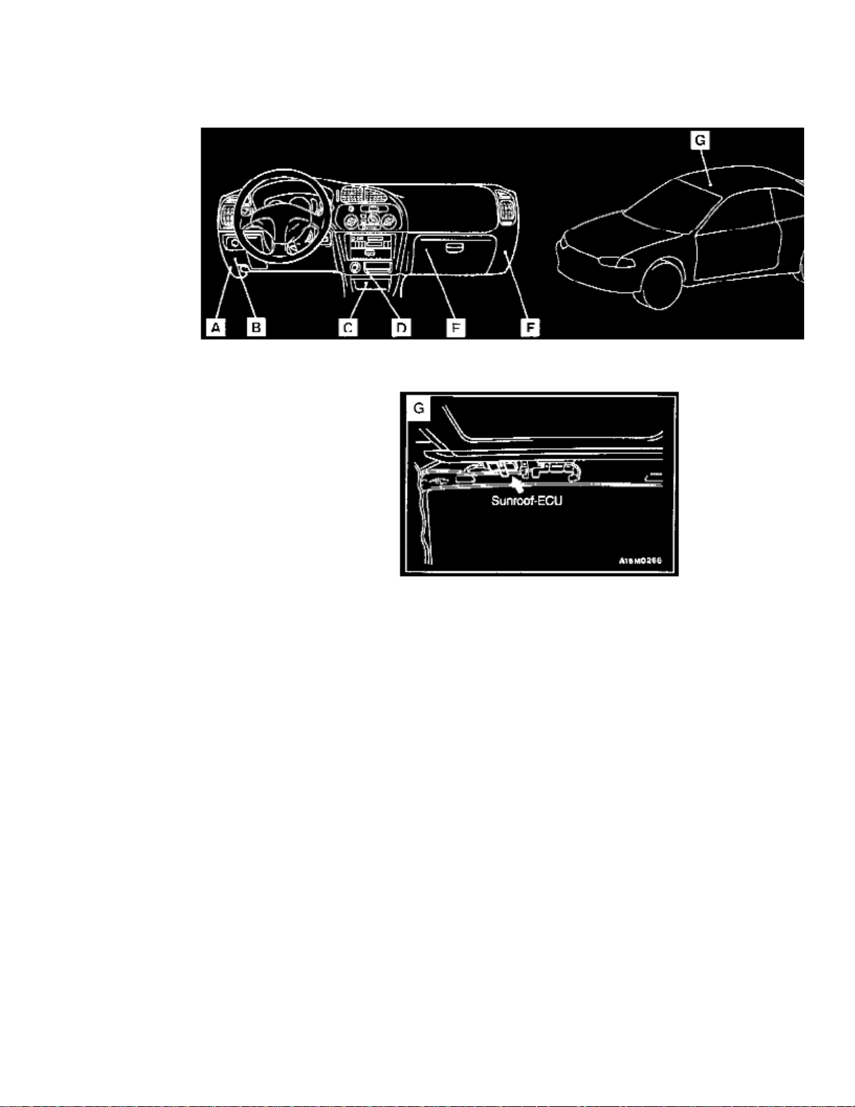
ETACS-ECU: Locations
Control Unit Locations Overall View
Control Unit Location Views A-F
Name Symbol
Page 3

ETACS-ECU A
Page 4

> Relays and Modules > Relays and Modules - Accessories and Optional Equipment > ETACS-ECU <--> [Alarm Module, (Vehicle Antitheft)] > Component Information > Locations > Page 7
Page 5

Page 6
> Relays and Modules > Relays and Modules - Body and Frame > Sunroof / Moonroof Module > Component Information > Locations
Sunroof / Moonroof Module: Locations
Control Unit Locations Overall View
Control Unit Location View G
Name Symbol
Sunroof-ECU G
Page 7

Page 8
> Relays and Modules > Relays and Modules - Brakes and Traction Control > Brake Fluid Pump Relay > Component Information > Locations
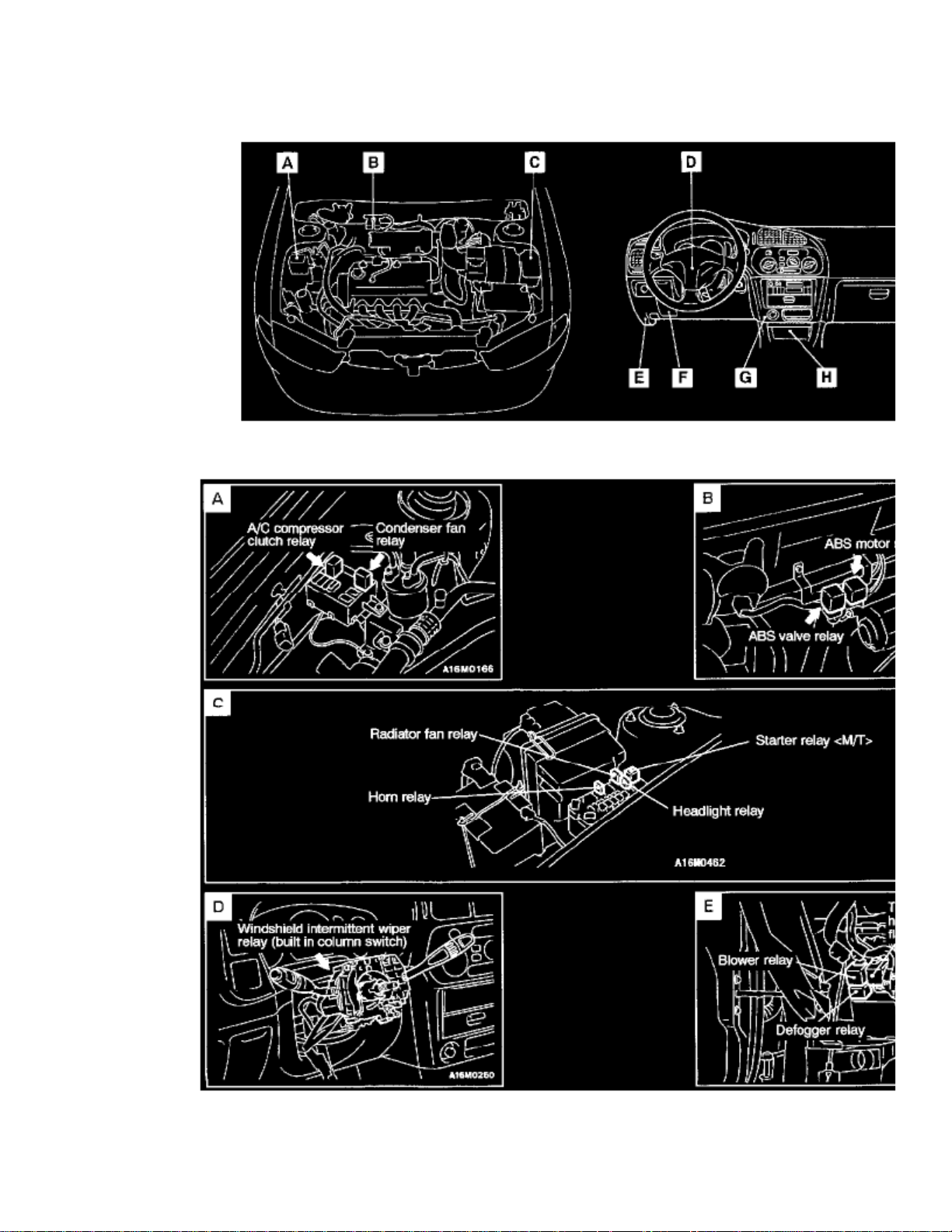
Brake Fluid Pump Relay: Locations
Relay Locations Overall View
Relay Location Views A-E
Page 9

Name Symbol
ABS Motor Relay B
Page 10
> Relays and Modules > Relays and Modules - Brakes and Traction Control > Brake Fluid Pump Relay > Component Information > Locations > Page 16
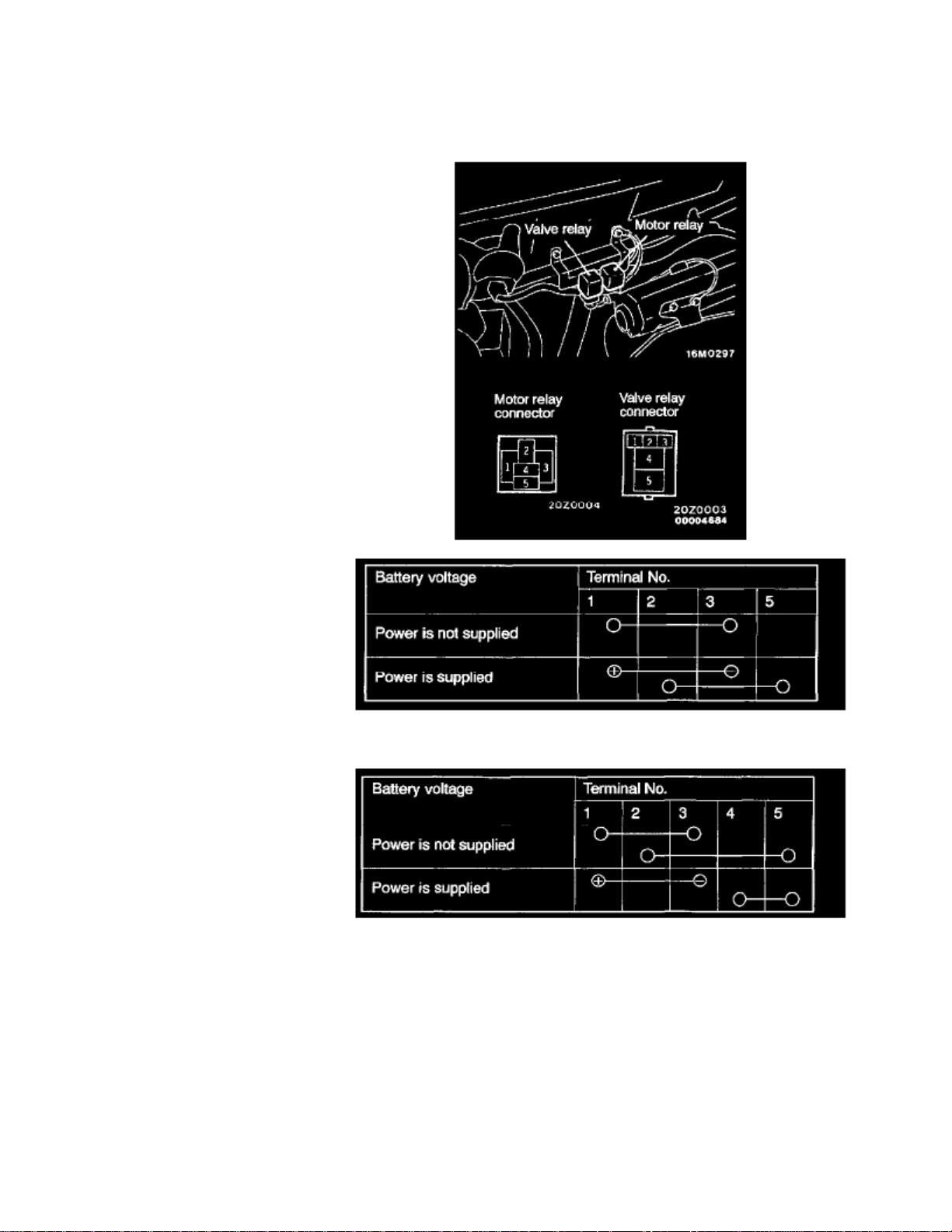
Brake Fluid Pump Relay: Testing and Inspection
MOTOR RELAY AND VALVE RELAY CONTINUITY CHECK
Motor relay
Valve relay
Page 11

Page 12

> Relays and Modules > Relays and Modules - Brakes and Traction Control > Brake Fluid Solenoid Valve Relay > Component Information > Locations
Brake Fluid Solenoid Valve Relay: Locations
Relay Locations Overall View
Relay Location Views A-E
Page 13

Name Symbol
ABS Valve Relay B
Page 14

> Relays and Modules > Relays and Modules - Brakes and Traction Control > Brake Fluid Solenoid Valve Relay > Component Information > Locations > Page 20
Brake Fluid Solenoid Valve Relay: Testing and Inspection
MOTOR RELAY AND VALVE RELAY CONTINUITY CHECK
Motor relay
Valve relay
Page 15

Page 16

> Relays and Modules > Relays and Modules - Brakes and Traction Control > Electronic Brake Control Module > Component Information > Specifications
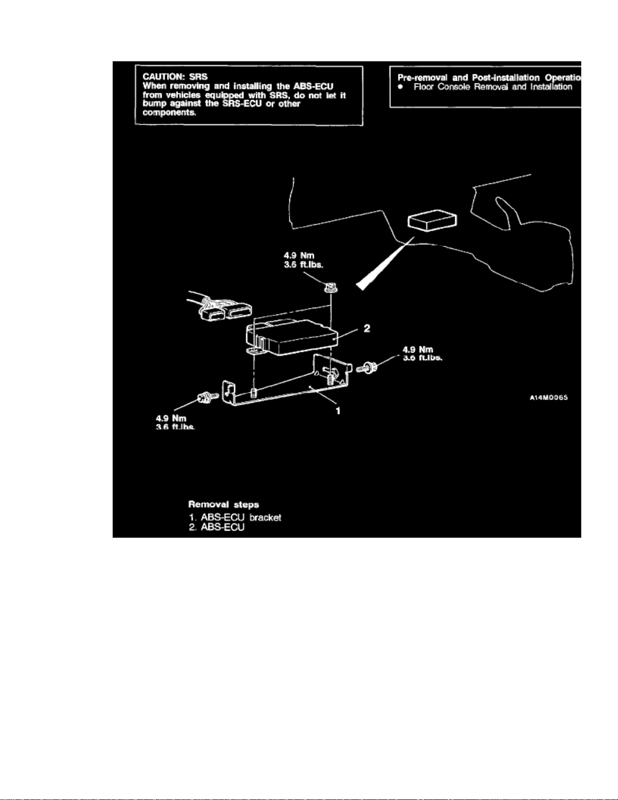
Electronic Brake Control Module: Specifications
TIGHTENING SPECIFICATIONS
ABS-Electronic Control Unit :(ECU)
Mounting Nuts ............................................................................................................................................................................. 4.9 Nm (43.2 in.lbs)Bracket Mounting Bolts ............................................................................................................................................................... 4.9 Nm (43.2 in.lbs)
Page 17

Page 18
> Relays and Modules > Relays and Modules - Brakes and Traction Control > Electronic Brake Control Module > Component Information > Specifications > Page 24
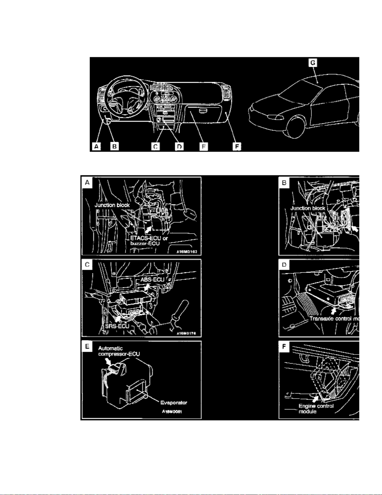
Electronic Brake Control Module: Locations
Control Unit Locations Overall View
Control Unit Location Views A-F
Name Symbol
Page 19

ABS-ECU C
Page 20

> Relays and Modules > Relays and Modules - Brakes and Traction Control > Electronic Brake Control Module > Component Information > Specifications > Page 25
Page 21

Page 22
> Relays and Modules > Relays and Modules - Brakes and Traction Control > Electronic Brake Control Module > Component Information > Specifications > Page 26
Page 23

Page 24

> Relays and Modules > Relays and Modules - Cooling System > Radiator Cooling Fan Motor Relay > Component Information > Locations
Radiator Cooling Fan Motor Relay: Locations
Relay Locations Overall View
Relay Location Views A-E
Page 25

Name Symbol
Radiator Fan Relay C
Page 26
> Relays and Modules > Relays and Modules - Cooling System > Radiator Cooling Fan Motor Relay > Component Information > Locations > Page 31
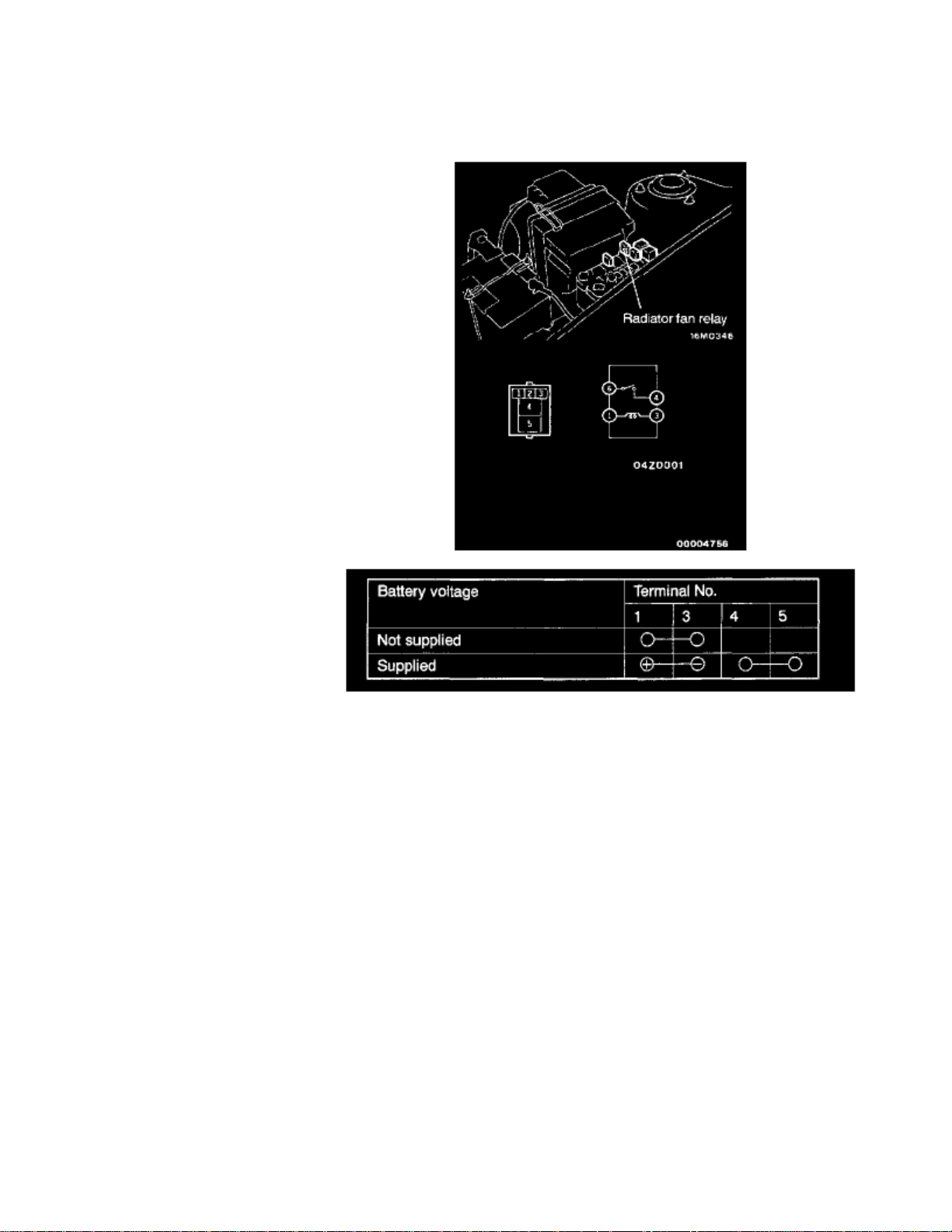
Radiator Cooling Fan Motor Relay: Testing and Inspection
INSPECTION
RADIATOR FAN RELAY CONTINUITY CHECK
Page 27

Page 28

> Relays and Modules > Relays and Modules - Cruise Control > Cruise Control Module > Component Information > Locations
Cruise Control Module: Locations
Control Unit Locations Overall View
Control Unit Location Views A-F
Name Symbol
Page 29

Auto-Cruise Control-ECU B
Page 30

> Relays and Modules > Relays and Modules - HVAC > Blower Motor Relay > Component Information > Locations
Blower Motor Relay: Locations
Relay Locations Overall View
Relay Location Views A-E
Page 31

Name Symbol
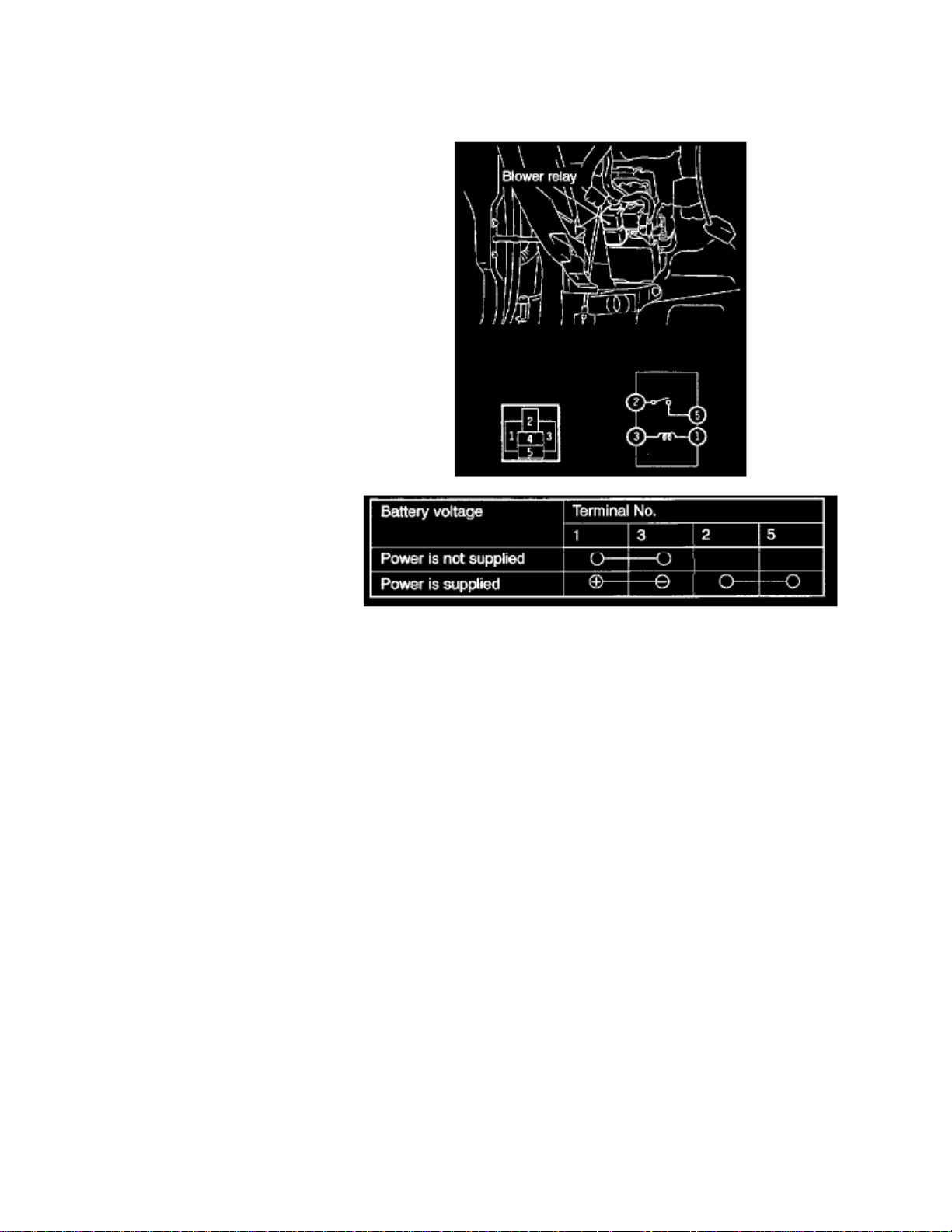
Blower Relay E
Page 32

> Relays and Modules > Relays and Modules - HVAC > Blower Motor Relay > Component Information > Diagrams > Diagram Information and Instructions
Blower Motor Relay: Diagram Information and Instructions
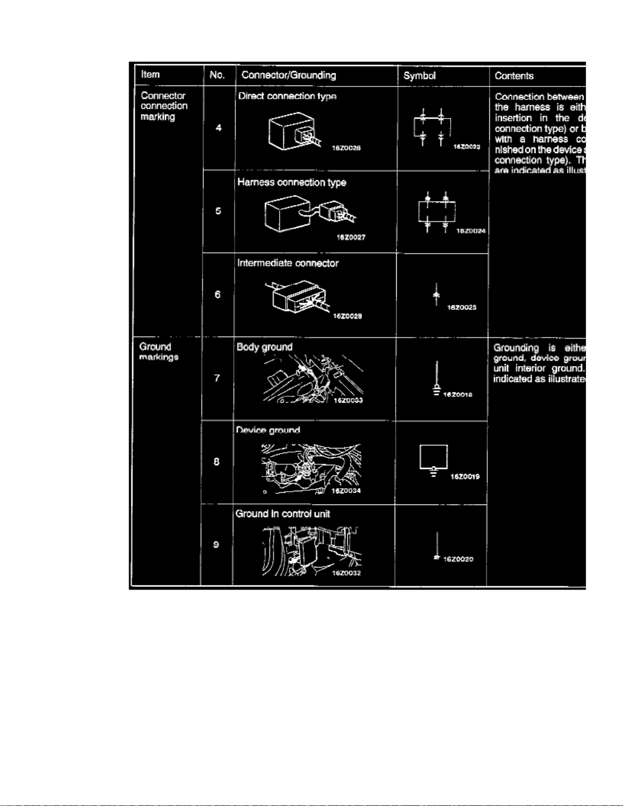
Connector and Ground Indicators
Page 33

> Relays and Modules > Relays and Modules - HVAC > Blower Motor Relay > Component Information > Diagrams > Diagram Information and Instructions > Page 42
Mirage Coupe LS L4-1834cc 1.8L SOHC MFI (1999)
Page 34

Page 35

> Relays and Modules > Relays and Modules - HVAC > Blower Motor Relay > Component Information > Diagrams > Diagram Information and Instructions > Page 43
Mirage Coupe LS L4-1834cc 1.8L SOHC MFI (1999)
Page 36

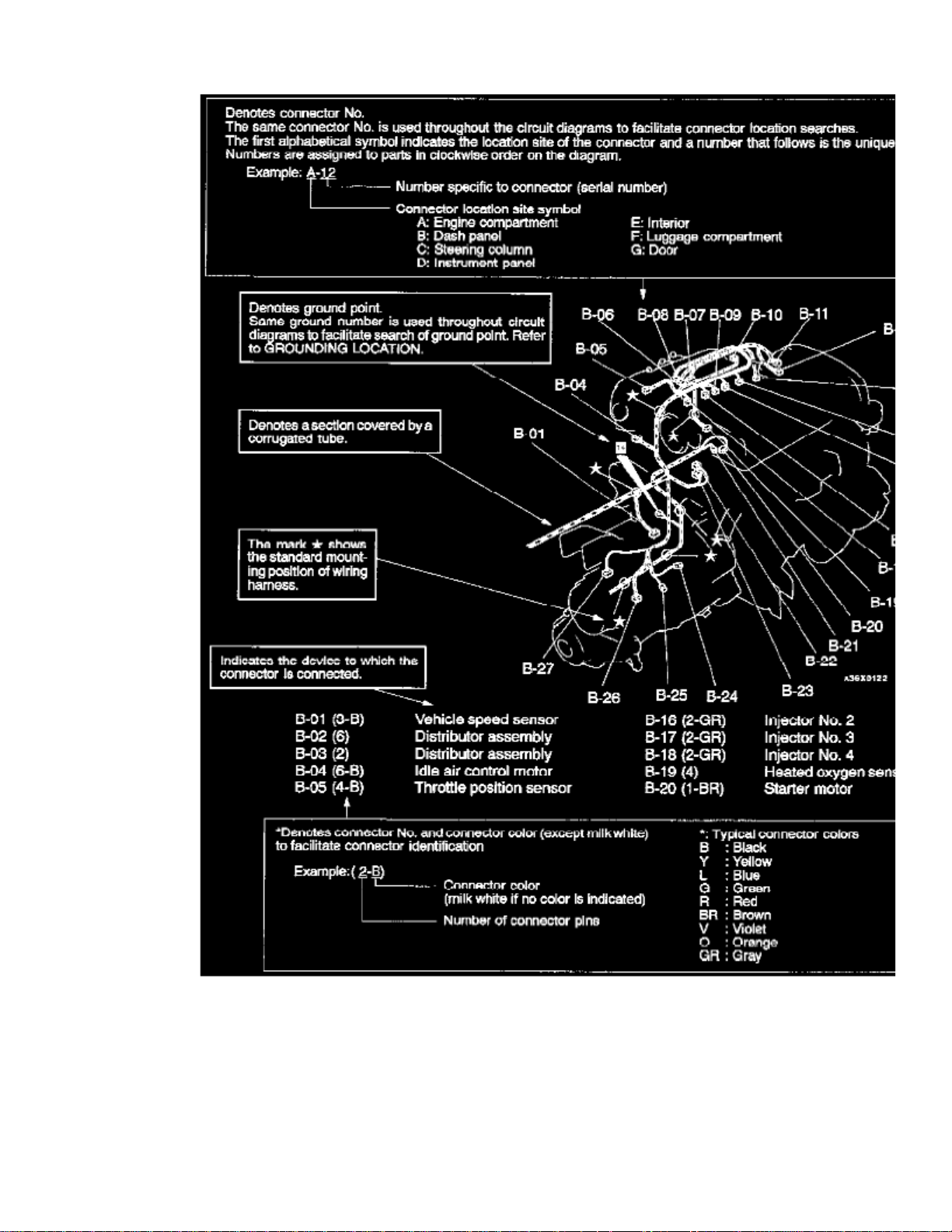
How to Read Circuit Diagrams
Page 37

> Relays and Modules > Relays and Modules - HVAC > Blower Motor Relay > Component Information > Diagrams > Diagram Information and Instructions > Page 44
Mirage Coupe LS L4-1834cc 1.8L SOHC MFI (1999)
Page 38

Page 39

> Relays and Modules > Relays and Modules - HVAC > Blower Motor Relay > Component Information > Diagrams > Diagram Information and Instructions > Page 45
Mirage Coupe LS L4-1834cc 1.8L SOHC MFI (1999)
Page 40

Page 41

> Relays and Modules > Relays and Modules - HVAC > Blower Motor Relay > Component Information > Diagrams > Diagram Information and Instructions > Page 46
Mirage Coupe LS L4-1834cc 1.8L SOHC MFI (1999)
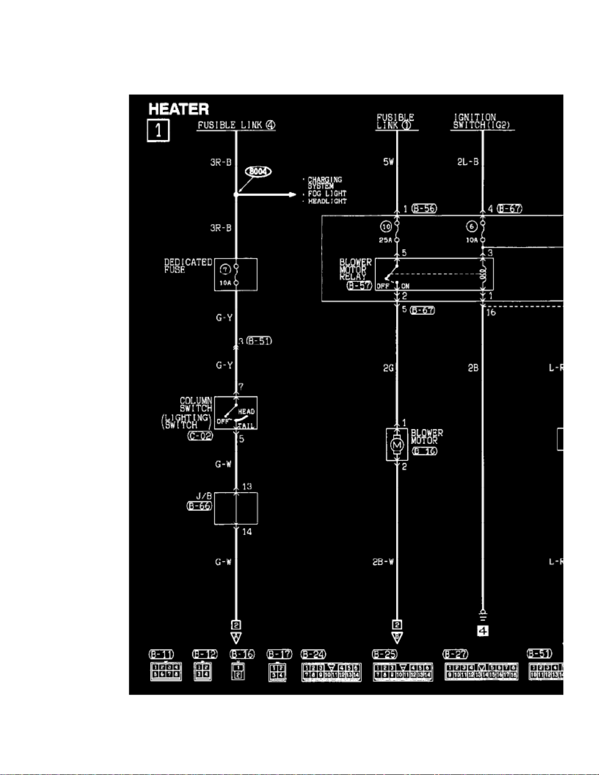
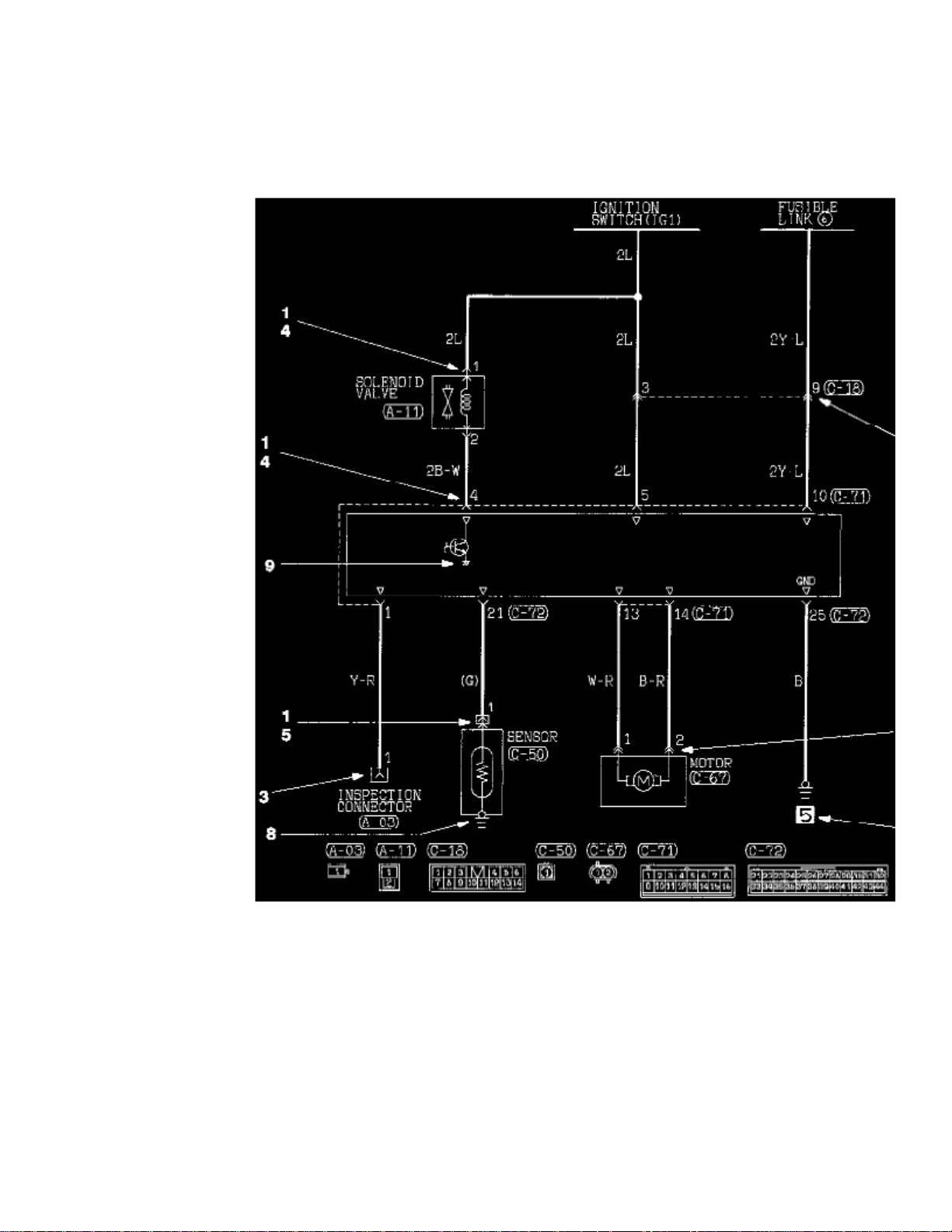
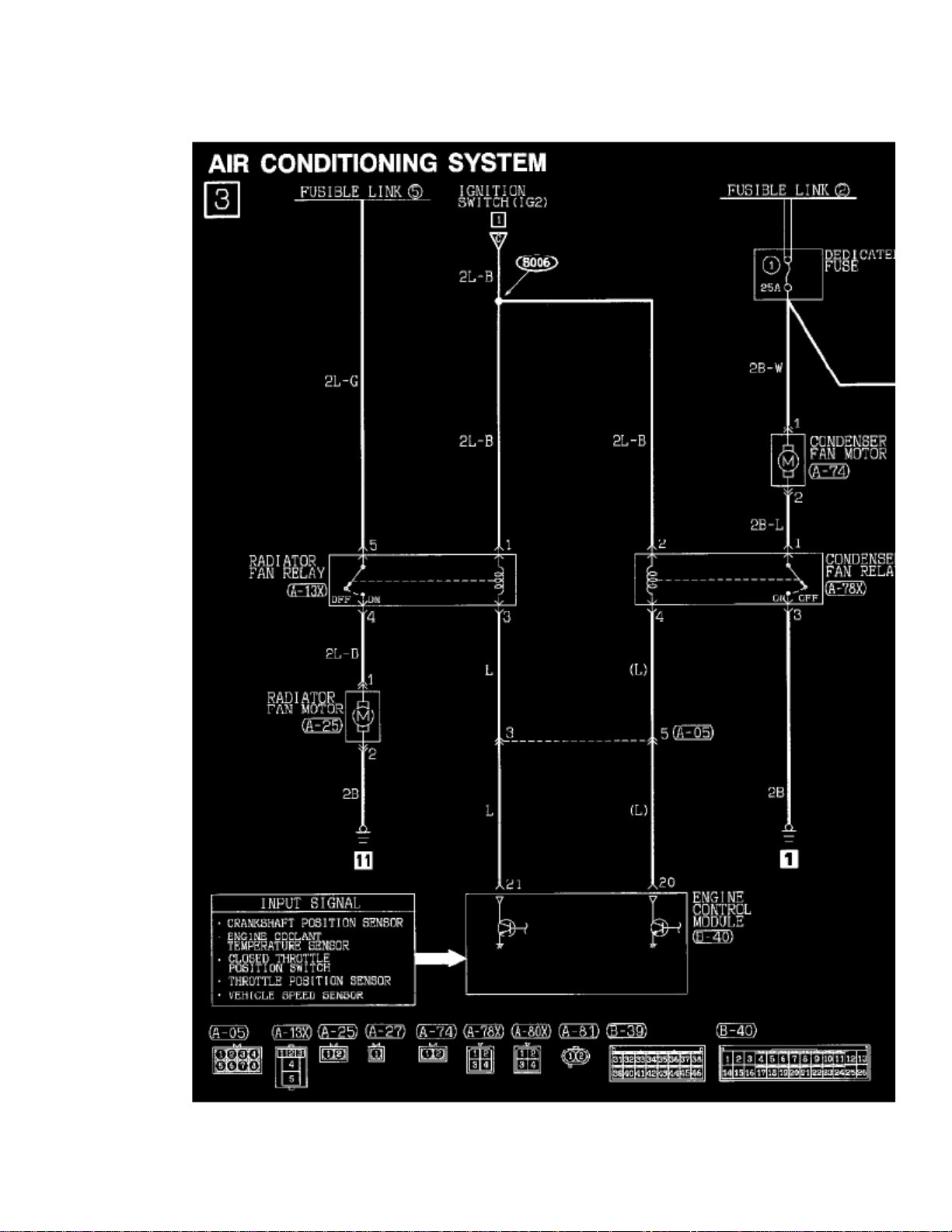
The circuit of each system is shown from the fuse (or fusible link) to ground. The power supply is shown at the top and the ground at the bottom to helpunderstand how the circuit flows.
How to Read Connector/Harness Diagrams
Page 42

The wiring harness diagrams clearly show the connector locations and harness routings at each site on actual vehicles.
Page 43

> Relays and Modules > Relays and Modules - HVAC > Blower Motor Relay > Component Information > Diagrams > Diagram Information and Instructions > Page 47
Mirage Coupe LS L4-1834cc 1.8L SOHC MFI (1999)
Page 44

Wire Color Codes
Page 45

> Relays and Modules > Relays and Modules - HVAC > Blower Motor Relay > Component Information > Diagrams > Diagram Information and Instructions > Page 48
Mirage Coupe LS L4-1834cc 1.8L SOHC MFI (1999)
Wire Color Codes
If a cable has two colors, the first of the two color code characters indicates the basic color (color of the cable coating) and the second indicates the
Page 46
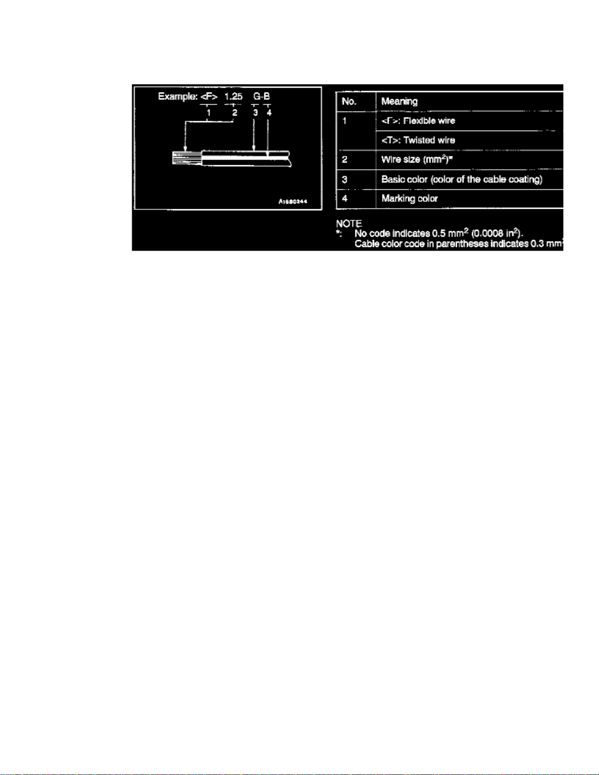
marking color.
Example of Wire Color Code
Page 47

Page 48
> Relays and Modules > Relays and Modules - HVAC > Blower Motor Relay > Component Information > Diagrams > Diagram Information and Instructions > Page 49
Blower Motor Relay: Electrical Diagrams
Page 49

> Relays and Modules > Relays and Modules - HVAC > Blower Motor Relay > Component Information > Diagrams > Diagram Information and Instructions > Page 50
Mirage Coupe LS L4-1834cc 1.8L SOHC MFI (1999)
Page 50

Page 51

> Relays and Modules > Relays and Modules - HVAC > Blower Motor Relay > Component Information > Diagrams > Diagram Information and Instructions > Page 51
Mirage Coupe LS L4-1834cc 1.8L SOHC MFI (1999)
Page 52

Page 53

> Relays and Modules > Relays and Modules - HVAC > Blower Motor Relay > Component Information > Diagrams > Diagram Information and Instructions > Page 52
Mirage Coupe LS L4-1834cc 1.8L SOHC MFI (1999)
Page 54

Page 55

> Relays and Modules > Relays and Modules - HVAC > Blower Motor Relay > Component Information > Diagrams > Diagram Information and Instructions > Page 53
Mirage Coupe LS L4-1834cc 1.8L SOHC MFI (1999)
Page 56

Page 57

> Relays and Modules > Relays and Modules - HVAC > Blower Motor Relay > Component Information > Diagrams > Diagram Information and Instructions > Page 54
Mirage Coupe LS L4-1834cc 1.8L SOHC MFI (1999)
Page 58

Page 59

Page 60
> Relays and Modules > Relays and Modules - HVAC > Blower Motor Relay > Component Information > Diagrams > Page 55
Blower Motor Relay: Testing and Inspection
BLOWER RELAY
Page 61

Page 62

> Relays and Modules > Relays and Modules - HVAC > Compressor Clutch Relay > Component Information > Locations
Page 63

Page 64
> Relays and Modules > Relays and Modules - HVAC > Compressor Clutch Relay > Component Information > Diagrams > Diagram Information and Instructions
Compressor Clutch Relay: Diagram Information and Instructions
Connector and Ground Indicators
Page 65

> Relays and Modules > Relays and Modules - HVAC > Compressor Clutch Relay > Component Information > Diagrams > Diagram Information and Instructions > Page 61
Mirage Coupe LS L4-1834cc 1.8L SOHC MFI (1999)
Page 66

Page 67

> Relays and Modules > Relays and Modules - HVAC > Compressor Clutch Relay > Component Information > Diagrams > Diagram Information and Instructions > Page 62
Mirage Coupe LS L4-1834cc 1.8L SOHC MFI (1999)
Page 68
How to Read Circuit Diagrams
Page 69

> Relays and Modules > Relays and Modules - HVAC > Compressor Clutch Relay > Component Information > Diagrams > Diagram Information and Instructions > Page 63
Mirage Coupe LS L4-1834cc 1.8L SOHC MFI (1999)
Page 70

Page 71

> Relays and Modules > Relays and Modules - HVAC > Compressor Clutch Relay > Component Information > Diagrams > Diagram Information and Instructions > Page 64
Mirage Coupe LS L4-1834cc 1.8L SOHC MFI (1999)
Page 72

Page 73

> Relays and Modules > Relays and Modules - HVAC > Compressor Clutch Relay > Component Information > Diagrams > Diagram Information and Instructions > Page 65
Mirage Coupe LS L4-1834cc 1.8L SOHC MFI (1999)
The circuit of each system is shown from the fuse (or fusible link) to ground. The power supply is shown at the top and the ground at the bottom to helpunderstand how the circuit flows.
How to Read Connector/Harness Diagrams
Page 74
The wiring harness diagrams clearly show the connector locations and harness routings at each site on actual vehicles.
Page 75

> Relays and Modules > Relays and Modules - HVAC > Compressor Clutch Relay > Component Information > Diagrams > Diagram Information and Instructions > Page 66
Mirage Coupe LS L4-1834cc 1.8L SOHC MFI (1999)
Page 76

Wire Color Codes
Page 77

> Relays and Modules > Relays and Modules - HVAC > Compressor Clutch Relay > Component Information > Diagrams > Diagram Information and Instructions > Page 67
Mirage Coupe LS L4-1834cc 1.8L SOHC MFI (1999)
Wire Color Codes
If a cable has two colors, the first of the two color code characters indicates the basic color (color of the cable coating) and the second indicates the
Page 78

marking color.
Example of Wire Color Code
Page 79

Page 80
> Relays and Modules > Relays and Modules - HVAC > Compressor Clutch Relay > Component Information > Diagrams > Diagram Information and Instructions > Page 68
Compressor Clutch Relay: Electrical Diagrams
Page 81

> Relays and Modules > Relays and Modules - HVAC > Compressor Clutch Relay > Component Information > Diagrams > Diagram Information and Instructions > Page 69
Mirage Coupe LS L4-1834cc 1.8L SOHC MFI (1999)
Page 82

Page 83

Page 84
> Relays and Modules > Relays and Modules - HVAC > Compressor Clutch Relay > Component Information > Diagrams > Page 70
Page 85

Page 86
> Relays and Modules > Relays and Modules - HVAC > Compressor Clutch Relay > Component Information > Testing and Inspection > Component Inspection
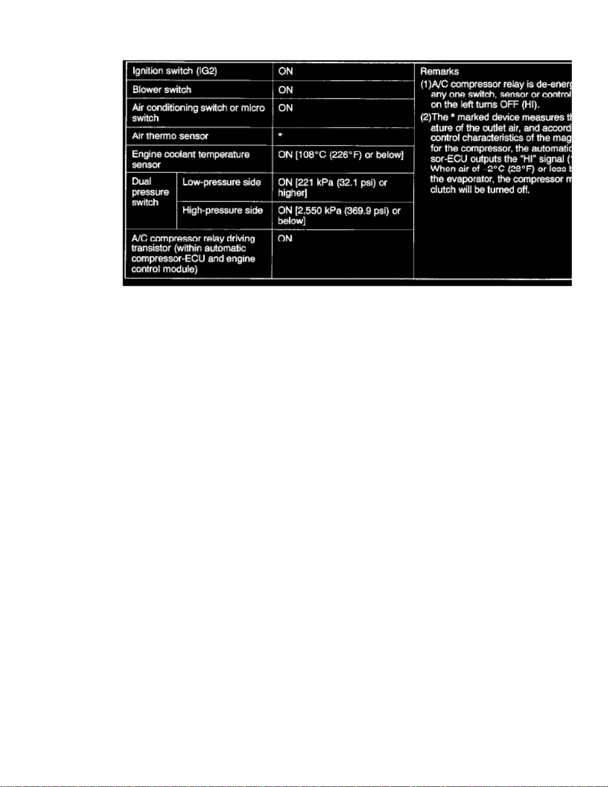
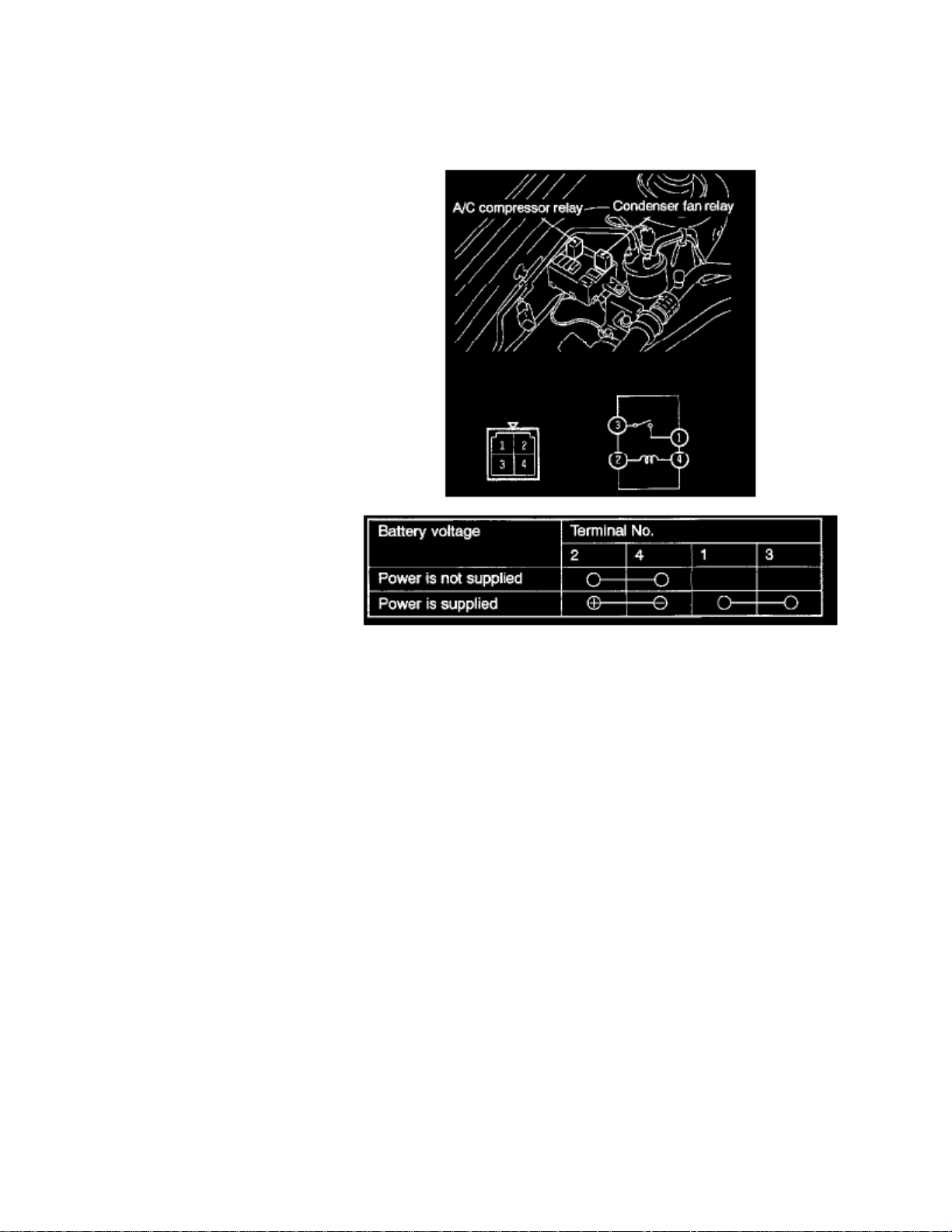
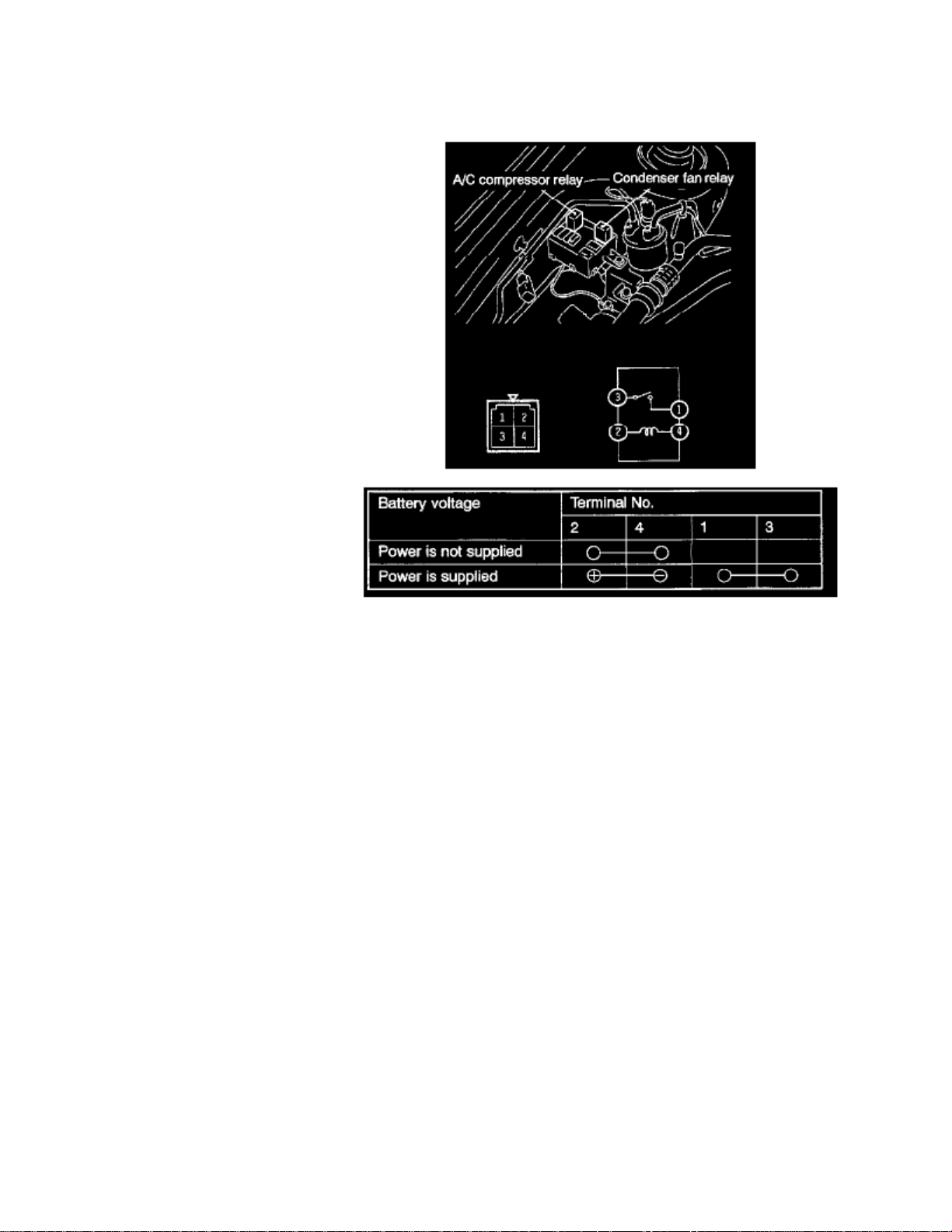
Compressor Clutch Relay: Testing and InspectionComponent Inspection
A/C COMPRESSOR RELAY, CONDENSER FAN RELAY
Page 87

Page 88

> Relays and Modules > Relays and Modules - HVAC > Compressor Clutch Relay > Component Information > Testing and Inspection > Component Inspection > Page 73
Page 89

Page 90
> Relays and Modules > Relays and Modules - HVAC > Condenser Fan Motor Relay, HVAC > Component Information > Locations
Page 91

Page 92
> Relays and Modules > Relays and Modules - HVAC > Condenser Fan Motor Relay, HVAC > Component Information > Locations > Page 77
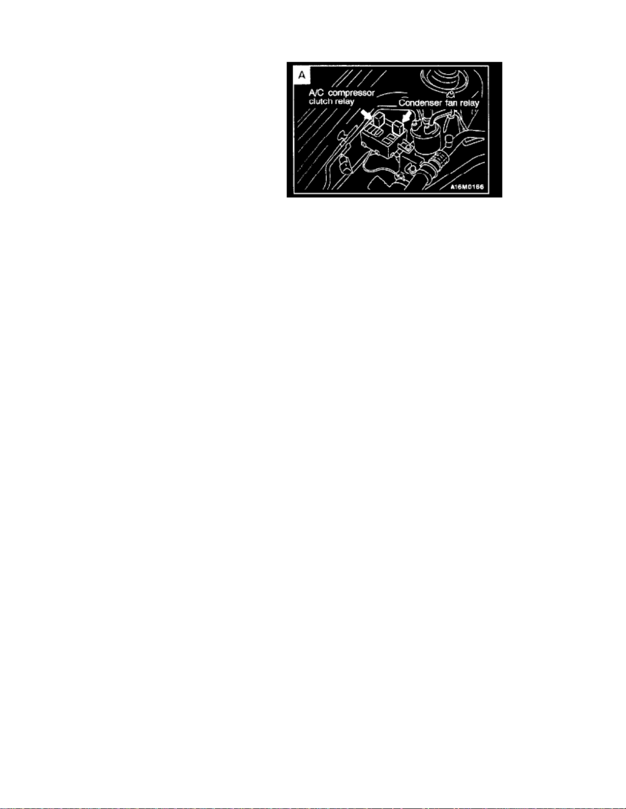
Condenser Fan Motor Relay: Testing and Inspection
A/C COMPRESSOR RELAY, CONDENSER FAN RELAY
Page 93

Page 94

> Relays and Modules > Relays and Modules - HVAC > Control Module HVAC > Component Information > Locations
Control Module HVAC: Locations
Control Unit Locations Overall View
Control Unit Location Views A-F
Name Symbol
Page 95

Automatic Compressor-ECU <A/C> E
Page 96

> Relays and Modules > Relays and Modules - Instrument Panel > Buzzer-ECU <--> [Audible Warning Device Control Module] > Component Information > Locations
Buzzer-ECU: Locations
Control Unit Locations Overall View
Control Unit Location Views A-F
Name Symbol
Page 97

Buzzer-ECU A
Page 98
> Relays and Modules > Relays and Modules - Instrument Panel > Buzzer-ECU <--> [Audible Warning Device Control Module] > Component Information > Locations > Page 85
Page 99

Page 100

> Relays and Modules > Relays and Modules - Instrument Panel > Panel Illumination Control Module > Component Information > Technical Service Bulletins > Dash Illumination Rheostat Circuit - Diagram Revision
Panel Illumination Control Module: Technical Service BulletinsDash Illumination Rheostat Circuit - Diagram Revision
NO: TSB-99-54-002 DATE: June, 1999 MODEL: 1999 Mirage
SUBJECT:REVISED RHEOSTAT CONFIGURATION AND CIRCUIT DIAGRAMS - SERVICE MANUAL REVISION
[TSB Revision TSB-99-54-002]
PURPOSE
This bulletin contains corrections to the rheostat configuration and circuit diagrams. The original information in the manual indicates that the rheostatconfiguration and wiring is different between vehicles which have auto-cruise and those that do not. Actually, the rheostat configuration and wiring is thesame for all vehicles (auto-cruise equipped and those without auto-cruise).
Write the TSB revision number of this bulletin in the "TSB Revision" box at the bottom of the affected service manual page.
AFFECTED VEHICLES
1999 Mirage
AFFECTED SERVICE MANUAL
1999 Mirage service manual, Volume 2, pages 80A-19 and 90-117
SERVICE MANUAL REVISIONS
 Loading...