

Page 1

Energy Saving Data Collecting Server
EcoWebServerIII
MODEL
MES3-255C-DM-EN
User’s Manual (Hardware)
● Before operating the instrument, you should first read thoroughly this operation
manual for safe operation and optimized performance of the product.
Deliver this user’s manual to the end user.
1
Page 2

2
Introduction
Item
Qty.
Item
Qty.
Energy Saving Data Collecting Server
(main unit)
1
(Black: 110 Ω, 1/2 W)(White: 130 Ω, 1/2 W)
CC-Link termination resistor
Black
× 2
White
× 2
Memory card (software)
1
IEC rail mounting adaptor
Small
× 2
Large
× 1
Configuration software (CD-R)
-Instruction manual included
1
IEC rail mounting kit
IEC rail mounting screw (M5 × 10)
2
Battery (built in the bottom of the main unit
server section)
1
IEC rail mounting square washer
2
Panel mounting screw (M4 × 14)
4
IEC rail stopper
2
Instruction Manual – Hardware
(*This document)
1
LAN port cap
2
Thank you for purchasing Mitsubishi Energy Saving Data Collecting Server (EcoWebServer III).
This instruction manual explains how to install and use the product.
Before using the product, read the instruction manual carefully for correct operation.
Be sure to read "1 Safety Precautions" to correctly handle the product.
Keep this instruction manual in a safe, accessible place for ready reference.
Make sure that this instruction manual will be delivered to the end users.
For details on setting EcoWebServerIII, refer to "User’s Manual - Setting (IB63919)".
For details on setting EcoWebServerIII, refer to "User’s Manual - Operating (IB63918)".
Packing materials and instruction manual
To reduce the load on the environment:
Packing materials use corrugated cardboard.
The instruction manual uses recycled paper.
Packaged items
Open the package and make sure all the following items are included.
Page 3

3
Table of Contents
1. Safety Precautions ................................................................................................................................................... 4
2. Main Features .......................................................................................................................................................... 8
3. Names and Functions of Parts ............................................................................................................................... 10
4. Procedures for Installation and Configuration ........................................................................................................ 16
5. Main Unit Installation (Installation de l'unité principale) .......................................................................................... 17
5.1 Installation on the IEC rail (35 mm wide) (Installation sur un IEC rail (35 mm de large)) .................................. 17
5.1.1. Mounting the IEC rail mounting adaptors (Montage d'adaptateur pour monter sur IEC rail) ....................... 17
5.1.2. Mounting the IEC rail fixing square washers (Montage de rondelle carrée pour fixer IEC rail) ................... 18
5.1.3. Installing the main unit on the IEC rail (Installation de l'unité principale sur IEC rail) .................................. 19
5.1.4. Fixing the main unit (Fixation de l'unité principale) ..................................................................................... 19
5.2 Direct installation on a panel (Installation directe une planche.) ....................................................................... 21
6. Battery Installation and Replacement .................................................................................................................... 23
6.1 Installing the battery ......................................................................................................................................... 23
6.2 Replacing the battery ....................................................................................................................................... 23
6.3 Setting the demand surveillance unit battery switch to ON .............................................................................. 24
7. IP Address Setting ................................................................................................................................................. 25
7.1 Setting an IP address ....................................................................................................................................... 25
7.2 Checking the IP address .................................................................................................................................. 30
7.3 Time limit synchronization of the demand surveillance section ........................................................................ 30
8. Connection Diagram .............................................................................................................................................. 31
8.1 Power supply section (Section de l'alimentation électrique) ............................................................................. 31
8.2 Ethernet communication section (CH1 for connection to PC) (Section de communication Ethernet) ............... 32
8.2.1. For initial setting (IP address setting) (Pour les réglages initiaux (adresse IP fixation)) .............................. 32
8.2.2. For operation (Pour opération).................................................................................................................... 32
8.3 Ethernet communication section (CH2 for connection to programmable logic controllers) (Section de
communication Ethernet (CH2)) ....................................................................................................................... 33
8.3.1. For operation (Pour opération).................................................................................................................... 33
8.4 CC-Link communication section (Section de CC-Link communication) ............................................................ 34
8.5 Contact output section (Section de sortie contact) ................................ ........................................................... 35
8.6 Demand surveillance unit section (Section de sortie contact) .......................................................................... 36
9. Specifications ......................................................................................................................................................... 37
9.1 Hardware specifications ................................................................................................................................... 37
9.2 Operating environment ..................................................................................................................................... 40
10. Outline Dimensions ................................................................................................................................................ 41
10.1 Outline dimensions ........................................................................................................................................... 41
10.2 Installation conditions ....................................................................................................................................... 42
11. Options................................................................................................................................................................... 42
12. Troubleshooting ..................................................................................................................................................... 43
13. Initialization of Main Unit Memory .......................................................................................................................... 44
14. Warranty ................................................................................................................................................................ 44
Page 4

4
1. Safety Precautions
Ambient temperature exceeds 0 to +55 ºC.
(Température ambiante excède 0º à +55 ºC.)
Daily average ambient temperature exceeds 35 ºC.
(Température ambiante quotidienne et moyenne excède 35 ºC.)
Relative humidity exceeds 5 to 95% or condensation is
observed.
(Humidité relative excède 5% à 95% ou condensation est
observée.)
Altitude exceeds 2000 m.
(Altitude excède 2000 m.)
Dust, corrosive gas, saline and oil smoke exist.
(Poussière, gaz corrosif, salin et huile fumée existe.)
Frequent vibration or impact exists.
(Vibration fréquente ou impact existe.)
Rainfall or water droplet hits the product.
(Pluie ou gouttelette frappe le produit.)
Exposed to direct sunlight.
(Exposé à lumière du soleil directe.)
Metal pieces or conductive materials blow.
(Pièce métal ou matière conducteur souffle.)
Under strong electromagnetic field or noise.
(Sous champ électromagnétique fort ou bruit.)
Cautions
The product shall be installed and wired by technicians specializing in electric work.
Always handle the end face of metal parts with care. The sharp part may cause injuries.
During threading or wiring work, take precaution so that any metal chip or a part of wire cut does not enter the
product.
Make sure to use the connection diagram for correct wire connection. Incorrect wiring may cause the device
malfunction, fire or electric shock.
Never work with live wires. Otherwise, it may lead to electric shock, fire or device problems.
Use electric wires of appropriate size. If an inappropriate size electric wire is used, it may cause fire due to
generated heat.
Use solderless terminals which fit the wire. If an inappropriate solderless terminal is used, wire breakage or contact
failure may occur, resulting in the device malfunction, failure, burnout, or fire.
To comply with the UL/c-UL standard, use wires whose temperature rating is 60 ºC/75 ºC for copper conductors.
(Pour UL/c-UL standard, utilisez le conduit en cuivre dont la température classée à 60 ºC /75 ºC.)
Part
Wire size
Appropriate solderless terminal
Power supply section
terminal block
0.75 to 2 mm2
RAV1.25-3.5
RAV2-3.5
CC-Link communication
section terminal block
Ver. 1.10-compatible CC-Link
dedicated cable
R1.25-3
Contact output section
terminal block
0.3 to 0.75 mm2
R1.25-3 (Solderless terminals with an
insulating sleeve cannot be used.)
Demand surveillance
section terminal block
0.5 to 1.3 mm2
TGV TC-1.25-11T (NICHIFU-made) or
equivalent
Make sure all the fittings are securely tightened. Failure in tightening may cause the device malfunction, fire, or
electric shock.
(Assurez-vous que tout le serrage est fermement serré. Manque de serrage peut causer mauvais fonctionnement
du dispositif, feu, ou commotion électrique.)
Fixing fittings must be tightened to the specified tightening torque. Excessive tightening may cause damage to
terminals or screws.
(Fixation du serrage doit être serrée à couple de serrage spécifié. Serrage excessif peut endommager du terminal
ou vis.)
Insufficient tightening may cause the device malfunction, fire, or electric shock.
(Serrage insuffisant peut causer mauvais fonctionnement du dispositif, feu, ou commotion électrique.)
If you use a twisted wire on the voltage input terminal, twist the wire end to prevent the thin wires (stick terminal)
from spreading out.
Accessory of LAN port cap can be used for dust-proof.
Please return the unit which you removed for wiring. The units are only support to be worked as EcoWebServerIII.
It will be not worked without using for EcoWebServerIII.
Please do not replace for any unit of EcoWebServerIII. Operation verification of EcoWebServerIII is confirmed as
the purchase. It may cause a malfunction or failure if EcoWebServerIII is used in any other combination.
Precautions concerning the operating environment and usage conditions
Do not use the product in the places specified below. Failure to observe this may result in malfunction or reduced life of
the product.
Precautions concerning the installation
Read this instruction manual before installation.
Page 5

5
Part
(Partie)
Tightening torque
(Couple de serrage)
Terminal screw for power supply section (M3.5 screw)
terminal block
(Borne de terminal pour terminal bloc (Vis M3.5)
dans la section d'alimentation électrique)
0.8 to 1.0 N•m
Terminal screw for CC-Link (M3 screw)
communication section terminal block
(Borne de terminal pour terminal bloc (Vis M3)
dans la section de CC-Link communication)
0.42 to 0.58 N•m
Mounting screw for CC-Link (M3.5 screw)
communication section terminal block
(Borne de montage pour terminal bloc (Vis M3.5)
dans la section de CC-Link communication)
0.66 to 0.89 N•m
Terminal screw for contact output (M3 screw)
terminal block
(Borne de terminal pour terminal bloc (Vis M3)
dans la section de contact sortie)
0.42 to 0.58 N•m
Mounting screw for contact output (M3.5 screw)
section terminal block
(Borne de montage pour terminal bloc (Vis M3.5)
dans la section de contact sortie)
0.66 to 0.89 N•m
Unit fixing screw (M3 × 12 screw)
(Vis pour fixation l'unité) (Vis M3)
0.36 to 0.48 N•m
Make sure that all the terminal covers are mounted after wiring. Failure to mount them may cause electric shock.
(Assurez-vous que tout les couvercle sont attachés. Manque d'attachement peut causer mauvais fonctionnement
du dispositif, feu, ou commotion électrique.)
Avoid installing in a panel where high pressure equipment is installed.
Please install a surge suppressor in the device which is prone to noise.
CC-Link communication signal line and other signal lines, auxiliary power supply line, the power supply frequency
input line to prevent the introduction of noise, please do not approach and unity of the power line or high voltage
line. Please separate the separation distance when the signal line and the power line / high voltage line are parallel
as a guide. (Excluding terminal block input section)
[CC-Link communication signal line]
Condition
Distance
All power lines
More than 100mm
[Other signal line / auxiliary power line / power frequency input line]
Condition
Distance
Power line of 600V or less
More than 300mm
Other power lines
More than 600mm
Please connect the shield wire of the CC-Link communication cable to the SLD terminal of each of the CC-Link
communication terminals.
And "SLD" of each terminal "FG" are connected inside the unit.
To prevent induction noise, keep control lines and communication cables as far away from power lines as possible.
(We recommend that you keep a distance of 100 mm or longer between them.)
Do not place them in a control panel containing high-voltage equipment.
Mount surge absorbers on equipment that is likely to produce noise.
Connect both ends of the shielded wire in a CC-Link communication cable to the "SLD" terminal of the units.
"SLD" and "FG" are connected to each other inside each unit.
Make sure to insulate the shielded wire using vinyl tape or the like.
For the actual usage, perform class D grounding dedicated for the "FG" terminal.
Perform insulation withstand voltage tests and insulation resistance tests without connecting the FG terminal to the
external case (ground).
Precautions concerning the preparation before use
Make sure that your installation site meets the requirements for the operation environment and usage conditions.
Before use, configure the settings of the product. Wrong settings may cause the product to malfunction.
Check the power ratings of the product.
After installing the product and performing wiring work, peel off the dustproof seal.
Failure to peel it off may cause the product to malfunction due to internal heat generation.
The product has a built-in lithium battery. It is not connected to the product when shipped from the factory. Connect it
before using the product.
(See "6. Battery Installation and Replacement".)
Precautions for use
Use the product within the ratings specified of this manual. If it is used outside the ratings, it may cause not only
malfunction or failure but also fire or burn damage.
Page 6

Settings including an IP address assignment are required to connect the product to the network (Ethernet). Before
use, perform an IP address assignment and other necessary network settings using the supplied configuration
software.
(See "7.1 Setting an IP address".)
The product is configured as follows when shipped from the factory:
IP address = 192.168.10.1, Subnet mask = 255.255.255.0, Gateway = None
If you connect the product directly to a single PC, these settings do not need to be changed.
The product has a built-in clock. Before use, set the current date and time using the supplied configuration software.
Before operating the product, make sure that an active live wire, etc. does not exist around the product.
If any bare wire is found, stop the operation immediately, and conduct necessary work such as insulation protection.
If the power is turned on immediately (within 5 seconds) after it is turned off, an out-of-spec inrush current (2 ms or
lower) may be generated. After power shutdown, wait at least 5 seconds before turning on power again.
Do not disassemble or modify the product. It may cause failure, electric shock or fire.
Cautions
Do not remove the seal on the side of this product. Such as maintenance and failure
analysis will be out of service without integral sealed.
Precautions for maintenance and inspection
Do not disassemble or modify the unit. It may cause failure, malfunction, personal injury, or fire.
Do not touch the terminals under energized conditions. It may cause electric shock, failure, or malfunction of the unit.
Be sure to externally turn off the input power before cleaning or additionally tightening unit mounting screws.
Otherwise, it may cause electric shock, failure, or malfunction of the unit.
Use a soft dry cloth to clean off dirt of the product surface.
Do not let a chemical cloth remain on the surface for an extended period of time nor wipe the surface with thinner or benzene.
Check the following items to use the product properly for a long time.
Items to be checked once or twice every 6 months:
(1) No damage on the product (2) No abnormality with LED indicators (3) No abnormal noise, smell or heat.
Item to be checked once a year:
(4) No looseness with installation and terminal block wiring. (Check this under de-energized conditions.)
Please replace the battery when a voltage drop occurred (BAT.LED on server section is red lighting) or every 3 years.
Checking for looseness with installation, terminal block wiring, and connector connection
Cautions
must be done under de-energized conditions.
When a power failure is occurred in a voltage drop state, clock and data might be reset.
Please configure again.
Precautions for storage
To store the product, turn off the power, remove wires, and store it in a plastic bag.
To keep the power off for a long time, remove the battery connector.
(The battery's total power-interruption backup time is 13,700 hours (1.57 years). If you continue to use the battery
after the expiration of the backup time, measured data may be deleted.)
For long-time storage, avoid the following places. Failure to observe this may result in malfunction or reduced life of the product.
Ambient temperature exceeds -25 to +75 ºC.
Daily average ambient temperature exceeds 35 ºC.
Relative humidity exceeds 5 to 95% or condensation is observed.
Dust, corrosive gas, saline and oil smoke exist.
Altitude over 2000m.
Frequent vibration or impact exists.
Rainfall or water droplet hits the product.
Exposed to direct sunlight.
Metal pieces or conductive materials blow.
Under strong electromagnetic field or noise.
Precautions for disposal
The product shall be properly disposed of in compliance with the "Wastes Disposal and Public Cleansing Act."
The product has a built-in lithium battery in server section and demand control section. The lithium battery shall be disposed
of in compliance with your local regulations.
Cautions
There may be some electricity left in the lithium battery removed. Keep it away from other
metal parts because its contact with the metal parts may cause heat, rupture, or fire.
Network building
For inquiries about installation and configuration of web browsers and JavaVM (Java Virtual Machine) and their
technical issues, contact your network administrator or appropriate department.
For inquiries about installation and configuration of servers such as SMTP (mail transfer) servers and FTP (file) servers and
their technical issues, contact your network administrator, appropriate department, or the manufacturers for those servers.
We don't offer technical support for the above.
6
Page 7

When needed for keeping system security against illegal access from outside, users shoul d take proper measure.
We do not assume responsibility for any trouble arising from illegal access.
We recommend users to note the followings.
1) Use LAN for preventing illegal access from outside.
2) Take measures like firewall and VPN when connecting internet.
3) Before using, change the default account (login ID, password).
Set the account so as not to leak the accont information according to the following precautions.
Avoid using simple string like Name, birth date and numbers.
Set the complex loging ID and password at least 8 characters by mixing uppercase or lowercase
alphanumeric characters.
QR code attached on the product
The QR code attached on the product is intended for the management of pr oduct manufacturing and should not be
used by the customer.
Reading of the QR code using commercially available code readers is not guaranteed.
Special purposes
Please contact our sales staff when you consider applying the product to special purposes, including use with
devices and systems for nuclear engineering, aerospace engineering, medical care, or automobiles. (See the end of
this document for details.)
7
Page 8

8
2. Main Features
This product can be performed alarm output and contact operation using demand surveillance and
also save the data collected via CC-Link communications or MODBUS® from measuring
instruments and programmable logic controllers to this product.
The product is preinstalled with software needed to view the data saved. The data can be
downloaded via Ethernet to PCs connected to the Internet/Intranet. The statuses of demand
surveillance and the collected data can be viewed in graph or list format using a web browser on the
PC over the Intranet. Equipment efficiency can be checked in graph by collecting the loading time
and downtime of equipment and the numbers of processed products and non-defective products.
An alarm can be issued in given events, such as when the target demand, the upper/lower limit of
data collected, the specific consumption planned value, or the energy planned value is reached or
when a measuring point turns on or off. Abnormal states can be quickly detected by sounding
buzzers and turning on lamps.
With just a simple setup, the collected data can be sent to the devices in programmable logic
controllers, enabling easy coordination with the equipment control.
Installing a mail server (SMTP server) or file transfer server (FTP server) allows you to send email
notifications when the target demand is exceeded or an upper/lower limit alarm operates and to
save measured data in a CSV format by automatic transfer. With these features, whenever a trouble
occurs, you can handle it immediately.
Transfer of XML files with an air-conditioner controller allows automatic control of lighting and air
conditioning according to the demand level.
Installing a clock server (SNTP server) allows clock synchronization among the equipment that
supports SNTP server capabilities.
* Do not use this feature the clock is based on the time of a transaction meter.
Page 9

9
Configuration example
EcoMonitorPro
電子式マルチ
指示計器
EMU3
シリーズ
接点入力
アナログ入力
温度入力
MELSEC-Q 電力計測ユニット
(CC-Link ローカル局経由)
CC-Link
MDU
ブレーカ
EcoWebServerIII (This Product)
Ethernet
Ethernet
View the graph (Internet Explorer)
EcoWebServerIII setting software
CC-Link terminals
PLC data collecting
Write collected
data to PLC
device
Transfer collected
file
Report by Email
EcoWebServerIII
Time adjustment
Client PC
Output the alarm status, data upper/lower
limit over and operation status, etc.,
to a lamp or buzzer
GOT
空調 コントローラ
PLC
PLC
PLC
FTP Server
SMTP Server
SNTP Server
EMU3
Series
MDU
braker
Electronic
multimeasuring
instrument
Contact input
Analog input
Temperature input
MELSEC-Q energy
measuring module
(via CC-Link local station)
(File server)
(Mail server)
(Time server)
Air controller
MC protocol client
(PATLITE network
monitoring lamp)(*1)
Input a demand
pulse signal
Ethernet (MODBUS® TCP)
MODBUS® TCP terminals
MODBUS® TCP ⇔
MODBUS® RTU
Protocol converter
RS-485 (MODBUS® RTU)
MODBUS® RTU terminals
*1 Limited to be a MC protocol client.
Page 10

10
7-segment LED display
Displays an error code when an
error is detected on the product.
Also displays the IP address set in
the product when you start it up in
the IP address display mode.
Front
Contact output terminal block
Contacts are closed when surveillance
conditions are satisfied. Connect
external devices such as buzzers or
lamps.
CC-Link
Station number setup switch
CC-Link
Transmission speed
setup switch
LED indications
Indicates the statuses of the
product.
LAN interface CH2
Used to connect programmable
logic controllers, GOT, or
MODBUS® terminal.
CC-Link terminal block
Connect a CC-Link
communication cable.
LAN interface CH1
Used to connect a PC.
USB interface
Unused.
LED indications
Indicates the statuses of
the product.
Demand control
terminal block
necessary voltage for
demand monitoring.
Connected by dedicated
pulse cable. (*1)
BAT.SW
Switch for the
backup battery
build-in the unit.
TS
Time adjustment
when connected to
transaction meter.
Power supply
section *1
Server
section
CC-Link
communication
section
Contact
output
section
Demand
control
section
EcoServerⅢ
3. Names and Functions of Parts
*1 Demand control section requires for additional power.
It is necessary to connect AC100 to 240V (+10%,-15%) 50/60Hz to V1,V2 in demand terminal block.
It is possible to take the power from the power supply section
Do not use UPS, SAG and etc. to supply the power.
Page 11

11
Battery storage section
Battery is stored here.
Open the cover to
connect a connector.
Bottom
Front
(with the server section cover opened)
Front
(with power supply cover opened)
Power supply
terminal block
Connect to
power supply. (*2)
MODE switch
Set it to the RUN position for
normal operation.
RESET switch
Use to reset the product.
Memory card
EJECT button
Push the button to eject the
memory card.
Memory card
Programs for collecting and
displaying data are stored
in this card.
It is also used to save
collected data.
(*3)
*2 Connect a power supply of 100-240 V AC (+10%, -15%) 50/60 Hz.
Do not connect any power supply other than the above, otherwise it may cause malfunction.
*3 The memory card should stay inserted in the product all the time.
Removing it while the power is on or the card is being accessed may cause the product to malfunction.
Before removing the card from the memory card slot, make sure to hold the RESET switch in the "SEL."
position and to turn the power off after the "CF CARD" LED goes out.
Incorrect procedure might cause data logging failure or equipment failure. Please consider UPS if the
power failure is frequently occurred.
Page 12

12
LED indications
Part
Indication
name
Status
Operation
Power
supply
section
POWER
Power supply
indication
Turns green: Power is on.
Server
section
RUN
Operation
indication
Turns green: MODE switch is set to RUN position (during regular
operation).
Turns off: MODE switch is set to STOP position (during the IP
address display mode).
CF CARD
Memory card
status
Turns green: Memory card is accessible.
Blinks green: Memory card is being ejected. (RESET switch is
held in SELECT position.)
Turns off: Memory card is ready to be ejected.
MODE
Operation
mode
Turns green: During regular operation
ERR.
Error
indication
Turns red: At the time of occurrence of a battery error
Blinks red: During initial startup after purchase
During a power outage due to battery exhaustion
STA.
Operation
status
Blinks green: During startup after the power is turned on
Turns green: Startup is complete.
100M
LAN
communication
Turns green: Connected at 100 Mbps
Turns off: Connected at 10 Mbps
SD/RD
Turns green: Connected to LAN
Turns off: Disconnected from LAN
Blinks: In the process of establishing LAN communication
CC-Link
communication
section
RUN
Operation
status of
CC-Link
communication
Turns green: CC-Link communication section is running normally.
Turns off: CC-Link communication section is in an abnormal
condition.
MST
CC-Link
master
Turns green: During normal operation
(This LED remains green all the time because the
product is fixed in CC-Link master mode during
operation.)
SD
CC-Link
communication
status
Blinks green: In the process of transmitting through CC-Link
communication
RD
Blinks green: In the process of receiving through CC-Link
communication
L RUN
CC-Link link
status
Blinks green: In the process of linking through CC-Link
communication
Turns off: No link through CC-Link communication
S MST
CC-Link
standby
master
Turns off: During normal operation
(This LED remains off all the time because the
product is fixed in CC-Link master mode during
operation.)
L ERR.
Error status of
CC-Link
communication
Blinks red at regular intervals: A switch on the CC-Link
communication section is operated
with power on.
Blinks red at irregular intervals: Termination resisters are not
mounted.
(The unit or CC-Link dedicated
cable is being affected by noise.)
Turns red: The setting does not correspond to
the connected equipment.
ERR
Error status
Lights green: Master stations overlap on the same line.
(This equipment is used with fixed CC-Link master mode)
The cable is disconnected, or being affected by noise.
Blinks red: The station number of the remote station is duplicated.
Contact
output
section
0 to 9, A to F
Contact
output status
Turns off: Contact output is open.
Turns red: Contact output is closed.
Page 13

13
Demand
surveillance
section
RUN
Operation
status of
demand
surveillance
Turns green: During normal operation
Turns off: When the internal power is a hardware error occurs
ERR
Error status
Turns red: At the time of occurrence of a hardware error, power
frequency out-of-range error, clock backup battery
voltage drop error, or outside time limit synchronism
error
Blinks red: Setting value out-of-range error
Turns off: During normal operation
ALM1/2
(*4)
Level 1/2
alarm status
Blinks red: At the time of occurrence of a level 1 alarm or
system alarm
Turns red: At the time of occurrence of a level 2 alarm
Turns off: Other than the above
ALML/F
(*4)
Limit/Fixed
alarm status
Turns red: At the time of occurrence of a limit/fixed alarm
Blinks red: At the time of occurrence of a system alarm
Turns off: Other than the above
BAT.ERR
Backup
battery status
for demand
monitoring
Section
Turns red: Clock backup battery voltage drop error is occurring
(or the battery switch is turned off)
Turns off: Other than the above
T
Input status of
outside time
limit
synchronism
signal or time
limit
synchronization
switch
Turns green: When the outside time limit synchronism signal is
being inputted or the time limit synchronization
switch is being pressed
Turns off: Other than the above
DS
Starting
status of
demand time
limit or status
of demand
time limit
Turns green (for 2 seconds): When the demand time limit starts or
the pressing of the time limit
synchronization switch is detected
Turns green: At the time of occurrence of an outside time limit
synchronism error
Blinks green: At the time of occurrence of a power frequency
out-of-range error
Turns off: Other than the above
R
Input status of
electric
energy pulses
Turns green: During the inputting of electric energy pulses
Turns off: Other than the above
Item
Specifications
Communication specifications
Ethernet (10BASE-T/100BASE-TX)
Communication speed
10 Mbps, 100 Mbps
Communication media
UTP (Unshielded twisted pair cable)
Max. segment length
100 m (to hub)
Item
Specifications
STOP
Turning the product off then on or resetting it with the switch in the "STOP" position displays
the IP address currently assigned to the product.
(7.2 Checking the IP address)
RUN
The product is usually used with the switch in the "RUN" position.
*4 System alarm of demand monitoring section contains the following error message.
Hardware error, build-in clock error, clock backup low battery error, power frequency range error,
time limit synchronism error.
LAN interface CH1, CH2 (100BASE-TX/10BASE-T)
MODE switch
Page 14

14
RESET switch
Item
Specifications
RES.
Use this switch to reset the product. After setting the switch to the "RES." position, you will
hear a click and see all the LEDs except "POWER" on the power supply section turn off.
Then, return the switch to the central position.
SEL.
Holding the switch in the "SEL." position during operation stops the reading/writing of the
memory card. Make sure to perform this procedure before turning the product off or
resetting it.
Cautions
Before turning the product off or resetting it, make sure to hold the RESET switch in the
"SEL." position and to see the "CF CARD" LED turn off.
If you turn the product off or reset it without performing this procedure, you may lose the
data saved in the memory card.
Terminal
symbol
Function
ERR.
ERR. terminal
(Unused)
FG
FG terminal (ground terminal)
LG
LG terminal
(Grounded through the power filter.)
N
Auxiliary power input
(Input ratings: Power supply 100 to 240 V AC)
L
Terminal
symbol
Function
DA
CC-Link communication line A
DB
CC-Link communication line B
DG
CC-Link communication line ground
SLD
CC-Link communication line shield
NC
(Unused)
Setting
Communication speed
0
156 kbps
1
625 kbps
2
2.5 Mbps
3
5 Mbps
4
10 Mbps
5 to 9, A to F
Prohibited
CompactFlash memory card slot (server section)
Insert the CompactFlash memory card supplied into this slot when the product is turned off.
The product will not work without inserting the CompactFlash memory card supplied into the slot.
The CompactFlash memory card must stay inserted in the slot during operation. The product can operate only
when the CompactFlash memory card is in the slot.
Terminal block (power supply section)
Terminal block (CC-Link communication section)
Connect both ends of the shielded wire in a CC-Link dedicated cable to the "SLD" terminal of the
unit.
Perform class D (Type 3) grounding work dedicated for the "FG" terminal of each unit.
"SLD" and "FG" are connected to each other inside each unit.
CC-Link station number setup switch (CC-Link communication section)
Set (Hold) the switch to 0.
(Note) It is set to 0 when shipped from the factory. Do not change the setting.
If it is set to any position other than 0, CC-Link communication cannot be established.
CC-Link communication speed setup switch (CC-Link communication section)
(Note 1) All the CC-Link terminal devices connected to the product must be set to the same communication speed. If they operate
at different communication speeds, communication cannot be established.
(Note 2) The switch is set to 0 (communication speed = 156 kbps) when shipped from the factory.
Page 15

15
Terminal block (contact output section)
Terminal
symbol
Function
0 to 9, A to F
Contact relay output terminals 0 to 9, A to F
COM
Contact relay output common terminal (common for output terminals 0 to 9, A to F)
NC
(Unused)
Terminal
symbol
Function
A+
System alarm output terminal (no-voltage normally-closed contact)
A-
TA
Outside time limit input terminal
TB
RT1
Pulse input terminal (RT2: positive terminal, RT3: negative terminal)
RT2
RT3
E
Earth
V1
Power frequency input terminal
V2
If the product is located at a distance from the transaction electricity meter:
The time limit can also be synchronized by short-circuiting TA and TB
instead of pressing TS (time limit synchronization switch). Time limit
synchronization can be facilitated by connecting a cable equipped with
a push button to the TA and TB terminals and extending it to near the
transaction electricity meter.
TA
TB
Terminal block (demand surveillance section)
NOTE: System alarm output by demand unit terminal is able to output the alarms below.
H/W error, clock error, low battery for clock backup, power frequency out of range error or
external pulse signal error.
Power OFF: output ON, Normal: output OFF, System alarm: output ON
BAT.SW <battery switch> (demand surveillance section)
When the demand function is used, turn on this switch to maintain the clock setting, even if
the product is powered off.
* Factory default of BAT.SW is OFF. Please turn it on before demand monitoring.
TS <time limit synchronization switch> (demand surveillance section)
Use this switch to synchronize the time limit.
Synchronize the time limit means time adjustment to the transaction electricity meter.
(Note) Press the switch in synchronization with the switching (on the hour or on the
half-hour) of the time limit of the transaction electricity meter.
Page 16
16
.3
Cautions
Read "Precautions concerning the installation" carefully to perform the operation safely.
If the product gives off abnormal noise, smell, smoke or heat, turn the power off
immediately.
Cautions
Wrong network settings may cause other devices on the network to malfunction.
The product is configured as follows when shipped from the factory:
IP address = 192.168.10.1, Subnet mask = 255.255.255.0, Gateway = None
If you connect the product directly to a single PC, these settings do not need to be changed.
4. Procedures for Installation and Configuration
Installation
The following explains the procedure from package opening to installation.
(1) Open the package.
(2) Check the packaged contents.
(See "Packaged items".)
(3) Insert the supplied CompactFlash memory card into the memory card slot.
(4) Connect the battery mounting connector.
(See "6.1 Installing the battery.")
(5) Check that the CC-Link station number setup switch is set to "0."
(See "CC-Link station number setup switch" in "3 Names and Functions of Parts.")
(6) Set a communication speed using the CC-Link communication speed setup switch.
(See "CC-Link communication speed setup switch" in "3 Names and Functions of Parts.")
(7) Install this product.
(See "5 Main Unit Installation.")
(8) Conduct wiring.
(See "8 Connection Diagram.")
(9) Check wiring conducted in step (8).
(10) Set BAT.SW on the demand surveillance section to ON.
(See "6.3 Setting the demand surveillance unit battery switch to ON.")
This completes the installation procedure.
Configuration
The following explains the procedure for getting the product ready for operation after installation.
(1) Use the supplied CD to install the configuration software on your PC.
(See " 2.3 Installation of the software " in User’s Manual – Setting.)
(2) Use the configuration software to set an IP address for the product.
(See "7 IP Address Setting.")
* If you use the factory default setting (IP address = 192.168.10.1), you do not have to perform this step.
(3) Use the configuration software to set a year, month, day, and clock for the product.
(See "Chapter 4 Operating Procedures, 4.8.1 Time Settings" in Instruction Manual – Configuration.)
(4) Configure the client computer to your network environment.
For details on settings, contact your network administrator.
For details on setting procedures, see the instruction manual of your computer or contact its manufacturer.
(5) Configure the web browser in the client computer.
(See "Chapter 2 Before Use, 2.4 Setting the Web Browser" in Instruction Manual – Operation.)
(6) Set necessary information such as connected devices and measuring points.
(See "Chapter 4 Operating Procedures" in Instruction Manual – Configuration.)
(7) Set information required for demand surveillance
(See "Chapter 4 Operating Procedures" in Instruction Manual – Configuration.)
(8) Synchronize the demand time limit.
(See "Chapter 4 Operating Procedures" in Instruction Manual – Configuration.)
(9) Check the product operation.
(See Instruction Manual – Operation.)
Page 17
17
5. Main Unit Installation (Installation de l'unité principale)
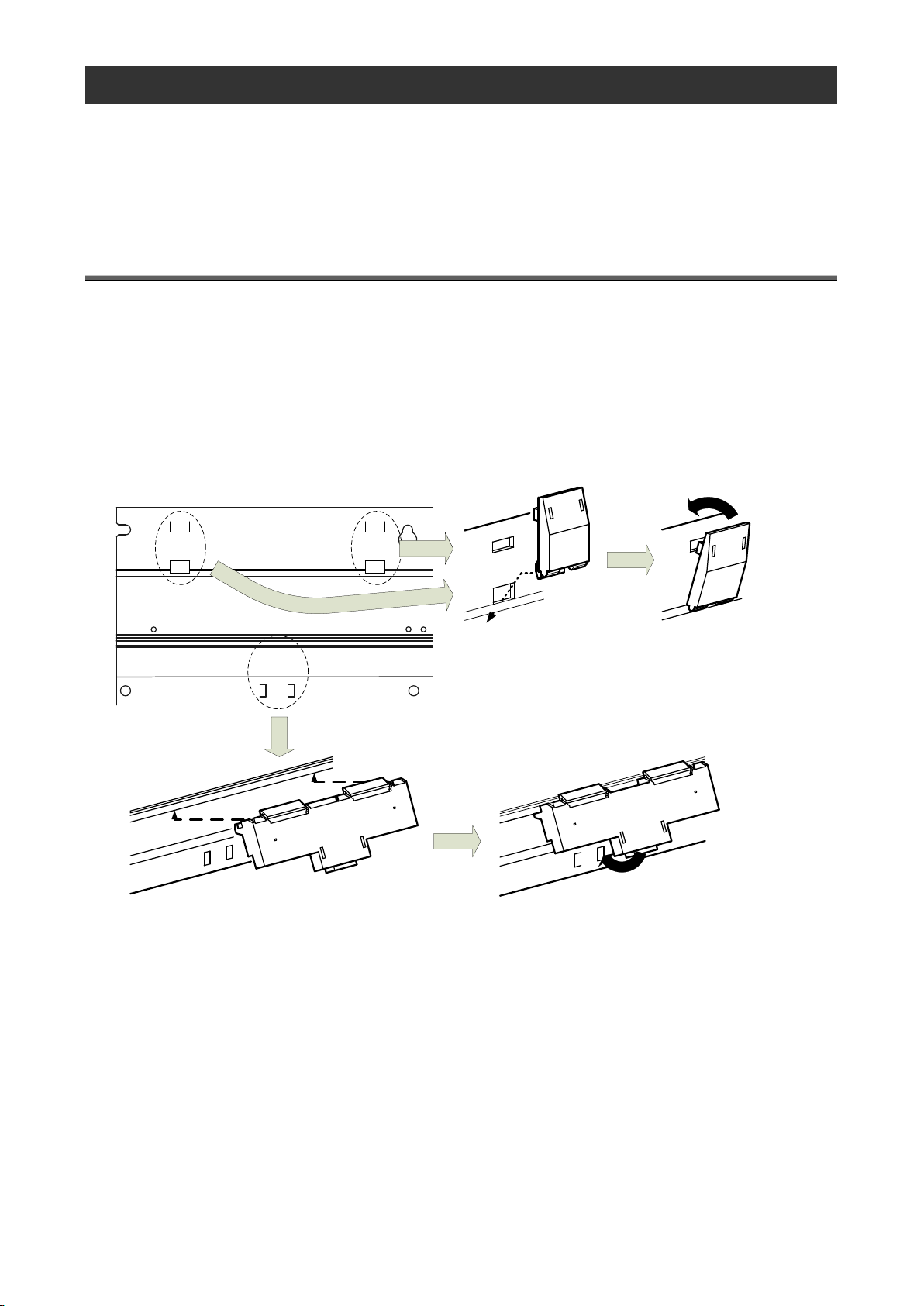
Place the hook of the
adaptor (small) into the
lower hole.
Placez le crochet de
l'adaptateur (petit) dans le
trou plus bas.
Push the upper part of the
adaptor (small) until you hear it
click.
Appuyez supérieur de
l'adaptateur (petit) jusqu'à vous
l'entendez claquement.
Push the lower part of the adaptor (large) until
you hear it click.
Appuyez inférieur de l'adaptateur (grand)
jusqu'à vous l'entendez claquement.
Insert the adaptor (large) from below into the
grooves in the base unit.
Insérez l'adaptateur (grand) de bas dans la
rainure du unité de base.
Back of the main unit
le dos de l'unité principale
This product can be installed in two ways, installation on an IEC rail (35 mm wide) and direct installation on a panel.
(Le produit peut être installé au deux moyens, installation sur un IEC rail (35 mm de large) et installation directe sur une
planche.)
5.1 Installation on the IEC rail (35 mm wide) (Installation sur un IEC rail (35 mm de large))
5.1.1. Mounting the IEC rail mounting adaptors
(Montage d'adaptateur pour monter sur IEC rail)
Mount the supplied IEC rail mounting adaptors (small × 2 and large × 1) on the back of the main unit.
(Montez adaptateurs pour monter sur IEC rail (petits × 2 et grand × 1) sur le dos de l'unité principale.)
Page 18
18
5.1.2. Mounting the IEC rail fixing square washers
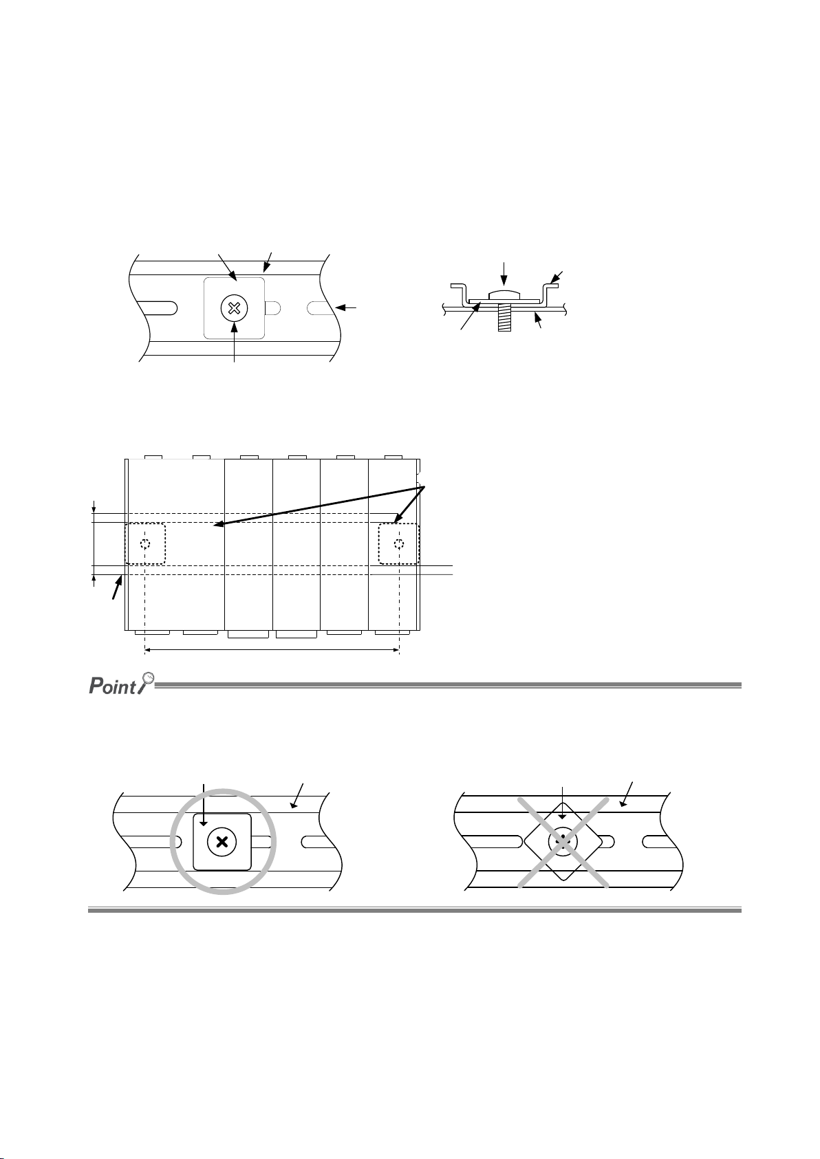
Mounting screw (M5 × 10)
Borne de montage (M5 × 10)
Square washer
Rondelle carrée
IEC rail
IEC rail
View A
Vue A
View A
Vue A
Mounting screw
Borne de montage
Square washer
Rondelle carrée
Installation side
(panel, etc.)
Côté d'installation
(planche, etc.)
IEC rail
IEC rail
80 to 90 mm
IEC rail
mounting
square washer
Rondelle
carrée pour
fixer IEC rail
IEC rail
IEC rail
35 mm
Make sure to place the square washers parallel to the IEC rail (the washers should fit into a groove in the rail).
(Assurez-vous à placer des rondelle carrées en parallèle de l'IEC rail.)
Square washer
Rondelle carrée
IEC rail
IEC rail
Square washer
Rondelle carrée
IEC rail
IEC rail
(Montage de rondelle carrée pour fixer IEC rail)
Use the square washers and mounting screws (M5 × 10) to fix the IEC rail to the position where the main unit will be
installed.
(Utilisez rondelles carrés et bornes de montage (M5 × 10) pour fixer l'IEC rail dans la position où l'unité principale
sera installée.)
Keep 80 to 90 mm between the square washers.
(Maintenez de 80 à 90 mm entre des rondelle carrées.)
Page 19
19
5.1.3. Installing the main unit on the IEC rail
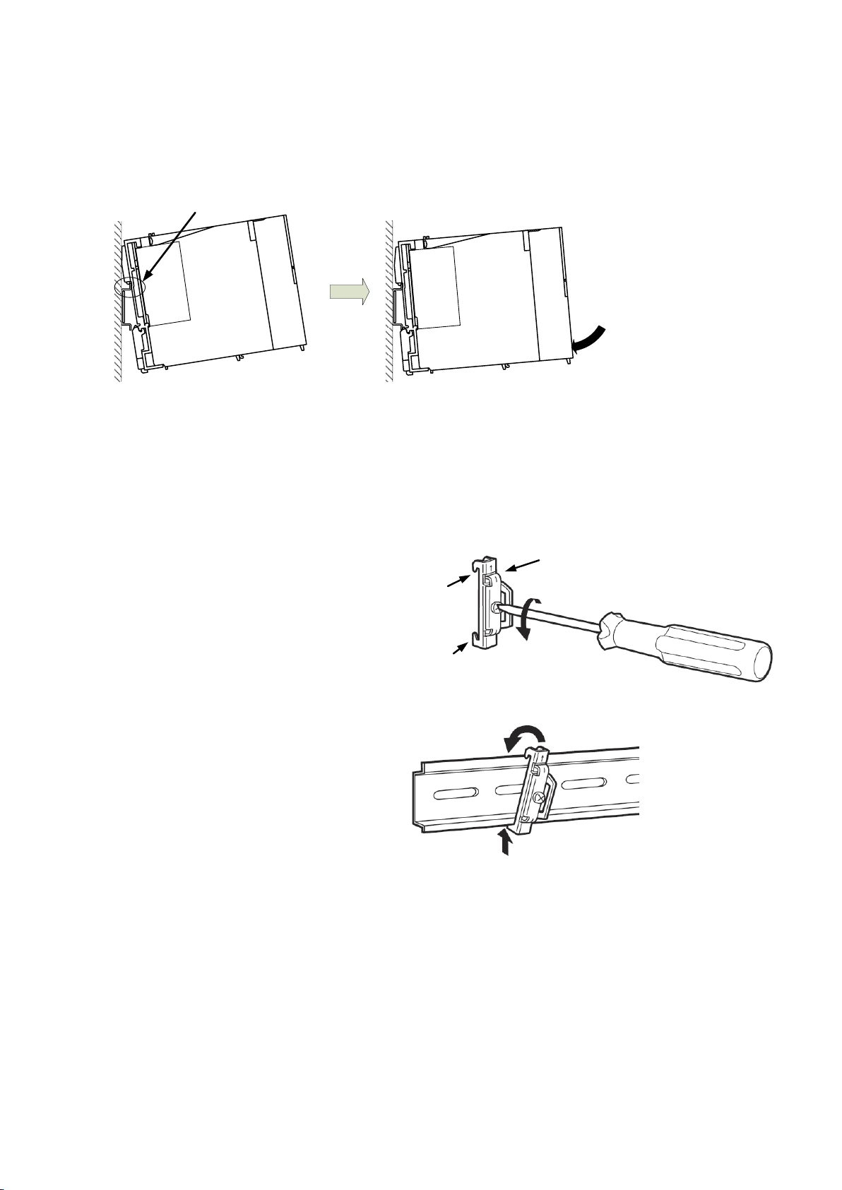
Hook the adaptor into the IEC rail.
Accrochez l'adaptateur à l'IEC rail.
Push the lower part of
the main unit until you
hear it click.
Appuyez inférieur de
l'unité principale jusqu'à
vous l'entendez
claquement.
(1) Loosen the screw on the top of the stopper.
(Desserrez le vis au sommet de ferrure en
métal de fixation.)
Stopper
Ferrure en métal de fixation
Hook
Crochet
Hook
Crochet
(2) Hitch the lower hook of the stopper to the
bottom of the IEC rail.
(Placez le crochet inférieur de ferrure en métal
de fixation en bas de l'IEC rail.)
(3) Hitch the upper hook of the stopper to the top
of the IEC rail.
(Placez le crochet supérieur de ferrure en
métal de fixation en supérieur de l'IEC rail.)
Hitch the hook to the top of the
IEC rail.
Placez le crochet en haut de l'IEC rail.
Hitch the hook to the bottom of the
IEC rail.
Placez le crochet en bas de l'IEC rail.
(Installation de l'unité principale sur IEC rail)
5.1.4. Fixing the main unit (Fixation de l'unité principale)
To prevent vibration when you transport the product installed in a panel, make sure to fix the product using the IEC rail
stoppers.
Page 20
20
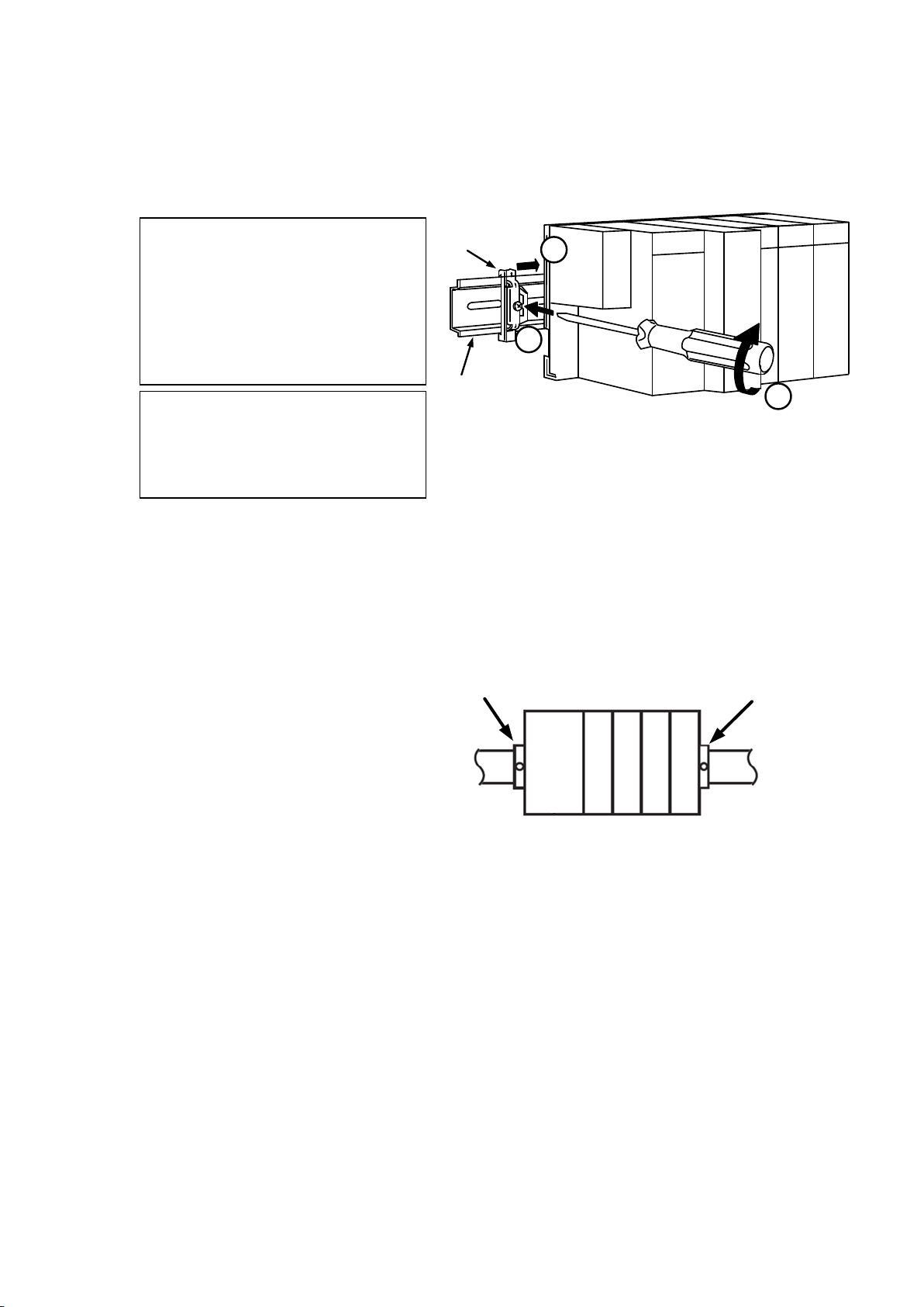
(4) Slide the stopper to come into intimate contact
with the main unit, and tighten the screw on
the top with a screwdriver.
(Tightening torque: 1.00 to 1.35 N•m)
(Glissez la ferrure en métal de fixation pour
toucher étroitement à l'unité principale, et
serrez le vis supérieur avec un tournevis.
(Couple de serrage: 1.00 à 1.35 N•m))
Stopper
IEC rail
(Left side)
(5) Do the same to fasten the stopper on the other
side to the main unit.
(Vérifiez que la ferrures en métal de fixation en
droite et gauche sont fermement attachées à
l'IEC rail.)
(6) Check that both right and left stoppers are
secured to the IEC rail.
(Vérifiez que la ferrures en métal de fixation en
droite et gauche sont fermement attachées à
l'IEC rail.)
Stopper
Ferrure en métal de fixation
Stopper
Ferrure en métal de fixation
Suivez de (1) à (3)
(1) Fixer le DIN rail
(2) Mettre la ferrure en métal de fixation à
l'unité principale
(3) Desserre la ferrure en métal de fixation
1
2
3
Follow the steps (1) to (3) shown in the
right figure to secure the main unit.
(1) Loosely fasten the stopper to the IEC
rail so that it will not come off the rail.
(2) Slide the stopper to come into intimate
contact with the main unit.
(3) Fasten the stopper while keeping it in
intimate contact with the main unit.
Page 21
21
5.2 Direct installation on a panel (Installation directe une planche.)
Cautions
●Please return the unit which you removed for wiring. The units are only support to be worked as
EcoWebServerIII.
It will be not worked without using for EcoWebServerIII.
●Please do not replace for any unit of EcoWebServerIII. Operation verification of EcoWebServerIII is
confirmed as the purchase. It may cause a malfunction or failure if EcoWebServerIII is used in any
other combination.
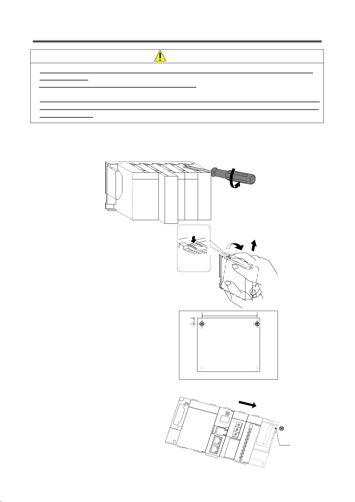
(1) Remove the fixing screws on the top of the demand surveillance section unit.
(Déboutonnez les vis pour fixation l'unité qui sont supérieurs de l'unité pour la section d'alimentation électrique
et de l'unité pour la section de contact sortie.)
(2) Remove the demand
surveillance section unit.
(Retirez l'unité pour la section
d'alimentation électrique et de
l'unité pour la section de
contact.)
Raise
Relevez
Push
Appuyez
Unit fixing hook
Crochet pour fixation l'unité
(3) Mount two panel mounting
screws (M4 × 12) on the board to
fix the upper side of this product.
(Montez deux bornes de
montage (M4 × 12) sur la
planche pour fixer le côté
supérieur du produit.)
Panel (Planche)
11 mm
170 mm
(4) Hook the notch in the right side
of this product on the right screw.
(Crochez le cran du côté droite
du produit sur le vis droite.)
Board(Planche)
Notch
Cran
Page 22
22
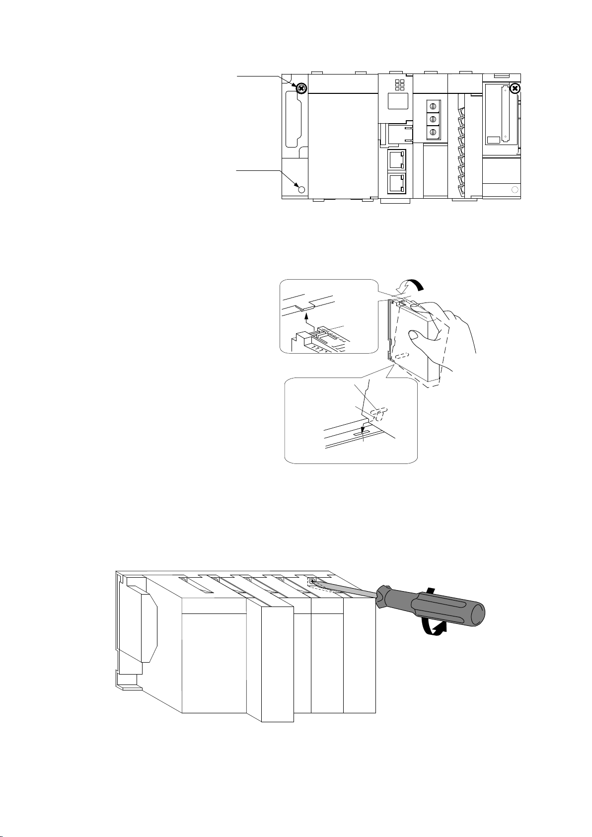
(5) Hook the hook slot in the left
side of this product on the left
screw.
(Crochez le cran du côté gauche
du produit sur le vis gauche.)
(6) Place mounting screws into the
right and left screw holes in the
lower side of this product, and
tighten all the mounting screws.
(Placez deux bornes de
montage dans les trous de vis
(en droite et gauche) en bas du
produit et serrer toue les bornes
de montage.)
Board(Planche)
Hook slot
Fente crochet
Mounting
screw hole
Trou pour
monter le vis
(Both right and
left sides)
(Les deux côté
en droite et
gauche )
(7) Mount the power supply section
unit and the contact output
section unit.
(Montez l'unité pour la section
d'alimentation électrique et
l'unité pour la section de contact
de sortie.)
Unit fixing hook
Crochet pour fixation l'unité
Unit fixing protrusion
Saillie de fixation l'unité
Unit fixing lever
Levier de fixation l'unité
Unit fixing hole
L'unité a arrangé le trou
(8) Tighten the unit fixing screws on the top of the power supply section unit and the contact output section unit.
(Tightening torque: 0.36 to 0.48 N•m)
* Tighten the screws securely to prevent the units from dropping.
(Serrez les vis pour fixation l'unité au sommet de l'unité pour la section d'alimentation électrique et de l'unité
pour la section de contact de sortie. (Couple de serrage: 0.36 à 0.48 N•m))
(Assurez-vous que le couple est serré)
Page 23
23
6. Battery Installation and Replacement(Server section)
Cautions
Make sure to perform battery replacement with power turned off.
Complete battery replacement within 3 minutes. If 3 minutes passes with the battery
removed, the data for the last 1 hour and the clock setting may be initialized. (The data and
setting values older than those for the last 1 hour are not initialized.)
If the IP address and clock settings are initialized, reconfigure those settings after backing
up the data.
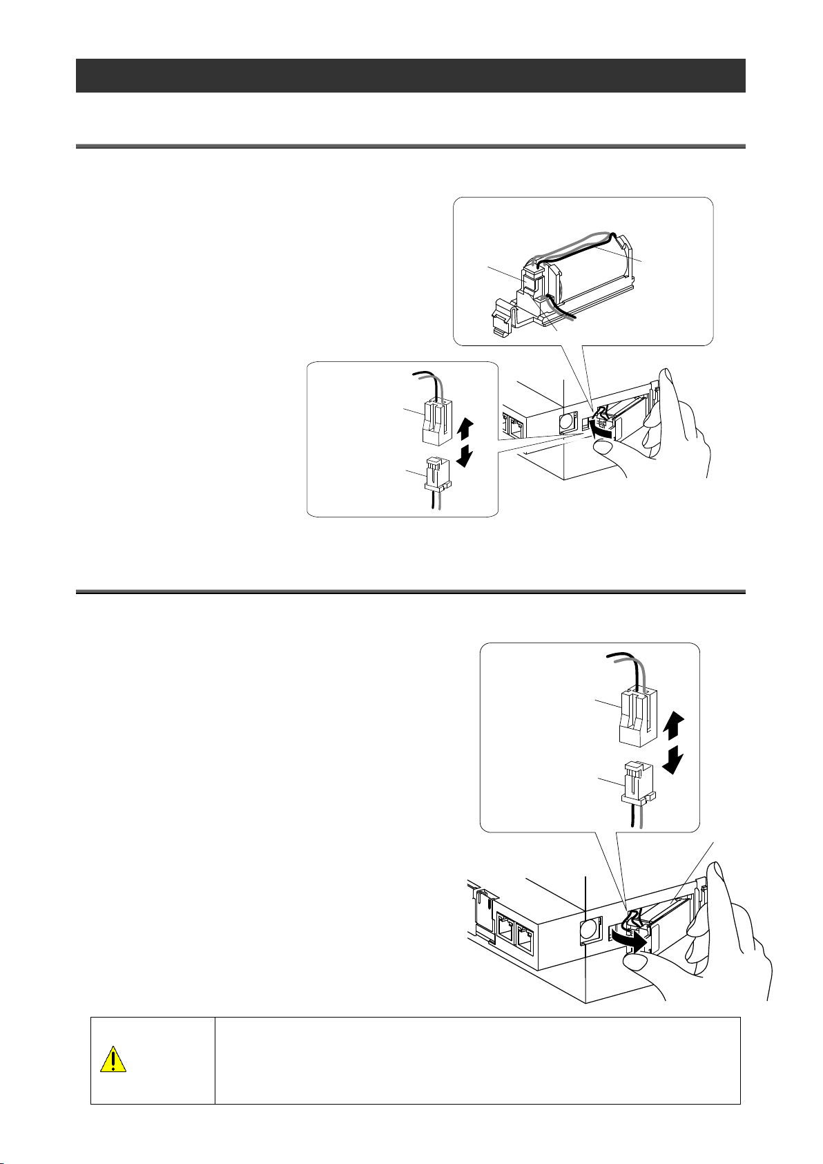
Connector
(main unit side)
Connector
(battery side)
Battery
Make bundles of excess lengths of lead wire
on the top of the battery (inside the main unit)
as shown below.
Connector
Connector stopper
Battery
lead wire
Connector
(main unit side)
Connector
(battery side)
6.1 Installing the battery(Server section)
The battery is shipped with the battery connector removed. Before use, make sure to connect the battery connector.
(1) Open the battery cover on the bottom of the server.
(2) Check that the battery is properly installed.
(3) Insert the connector on the battery into the case-side
connector pin, observing the correct orientation.
6.2 Replacing the battery(Server section)
When the battery reaches its end of life, the "ERR." LED on the server section turns red. Replace the battery with a new
one. (See "11 Options.")
(1) Open the front cover on the server section, and set the
(2) When the "CF CARD" LED turns off, turn the product off.
(3) Open the battery cover on the bottom of the server section.
(4) Remove the battery from the holder.
(5) Insert a new battery into the holder in the correct orientation
(6) Close the battery cover.
(7) Turn the product on.
RESET switch to the SEL position.
and connect the lead connector to the connector.
Page 24
24
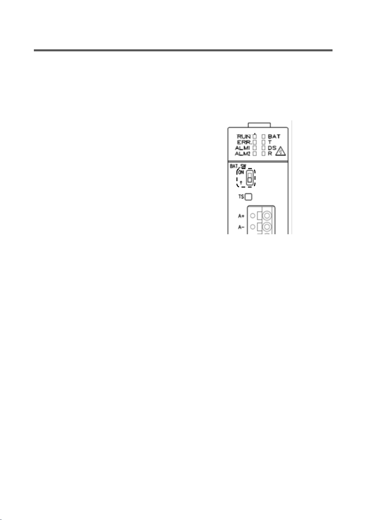
6.3 Setting the demand surveillance unit battery switch to ON
Before using the product, set the battery switch (BAT.SW) on the demand surveillance unit to ON.
(1) Before using the product, set the battery switch on the demand monitoring section to ON.
* Turning off the programmable logic controller with this switch set to OFF will reset the clock setting to the default
value (0:00, 1/1/2012).
(Note) Build-in clock in demand monitoring section will not be backup by the battery in C language controller.
Please make sure to set BAT.SW to ON before demand monitoring.
Page 25
25
7. IP Address Setting
IP address set in the product
IP address to be set to the PC
192.168.10.1
192.168.10.xx
xx is a value from 2 to 254.
* The upper 3 digits should be consistent
with those for the product.
7.1 Setting an IP address
(1) Install setting software to computer.
(2) Connect this product via a LAN straight cable or crossover cable to a PC that has the configuration software installed
in it.
(3) Take a note of the IP address set in the PC.
PC's IP address : . . .
PC's subnet mask : . . .
PC's default gateway : . . .
(4) Change the IP address set in the PC according to the IP address (factory setting: 192.168.10.1) set in the product.
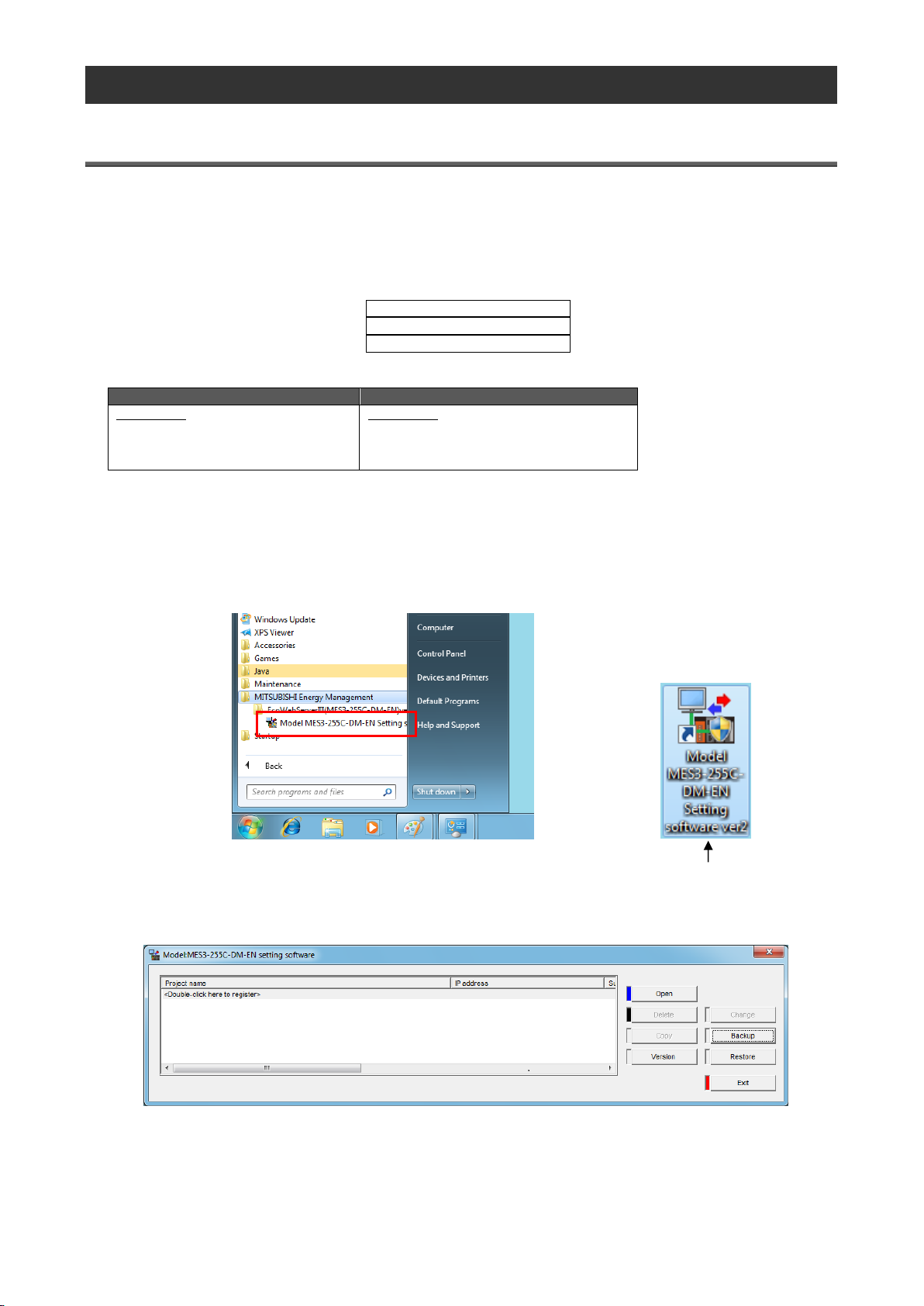
(5) Use the configuration software to set an IP address for EcoWebServerIII. Run the EcoWebServerIII setting software.
As the following sample by Windows® 7, displayed content might be different by OSs and installed applications.
[Start menu] > [All Programs] > [Mitsubishi Energy Saving Management Assistance] > [EcoWebServerIII
(MES3-255C-DM-EN)]
> Click [Model: MES3-255C-DM-EN Configuration Software ver3].
You can also launch the configuration software by double-clicking the Model: MES3-255C-DM-EN Setting
Software ver3 icon on the desktop.
After a few seconds, the following project management window appears.
Page 26
26
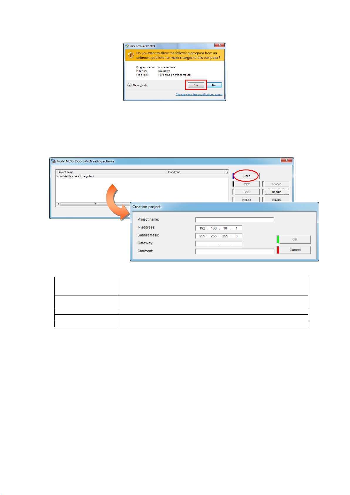
* If you are using Windows® 7 and the User Account Control dialog box appears as shown below, Click Yes to
Project name
Optional
(Specify a name such as "Factory A" or "Floor B" so that you can recognize it
as a project for EcoWebServer III.)
IP address
192.168.10.1
(Specify the factory default IP address.)
Subnet mask
255.255.255.0
Default gateway
Left blank
Comment
Optional
launch the configuration software.
(6) Create a new project.
Double-click <Double-click here to create a new project.> in the project management window.
Or
Select <Double-click here to create a new project.> and click Open.
Configure the following settings in the Create New Project window and click OK.
Page 27
27
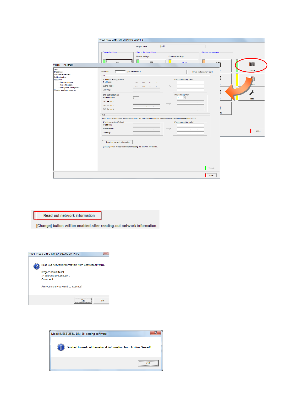
(7) Change the IP address for EcoWebServer III. Click Options in the project configuration window. Click IP address in
画像差し替え必要
the tree menu.
(8) Read the network information.
Click Read the network information.
Clicking the button displays the network information read confirmation message.
[Yes]: Executes network information reading.
[No]: Cancels network information reading.
After reading is completed, the messsage below is displayed.
ClickOK.
Page 28
28
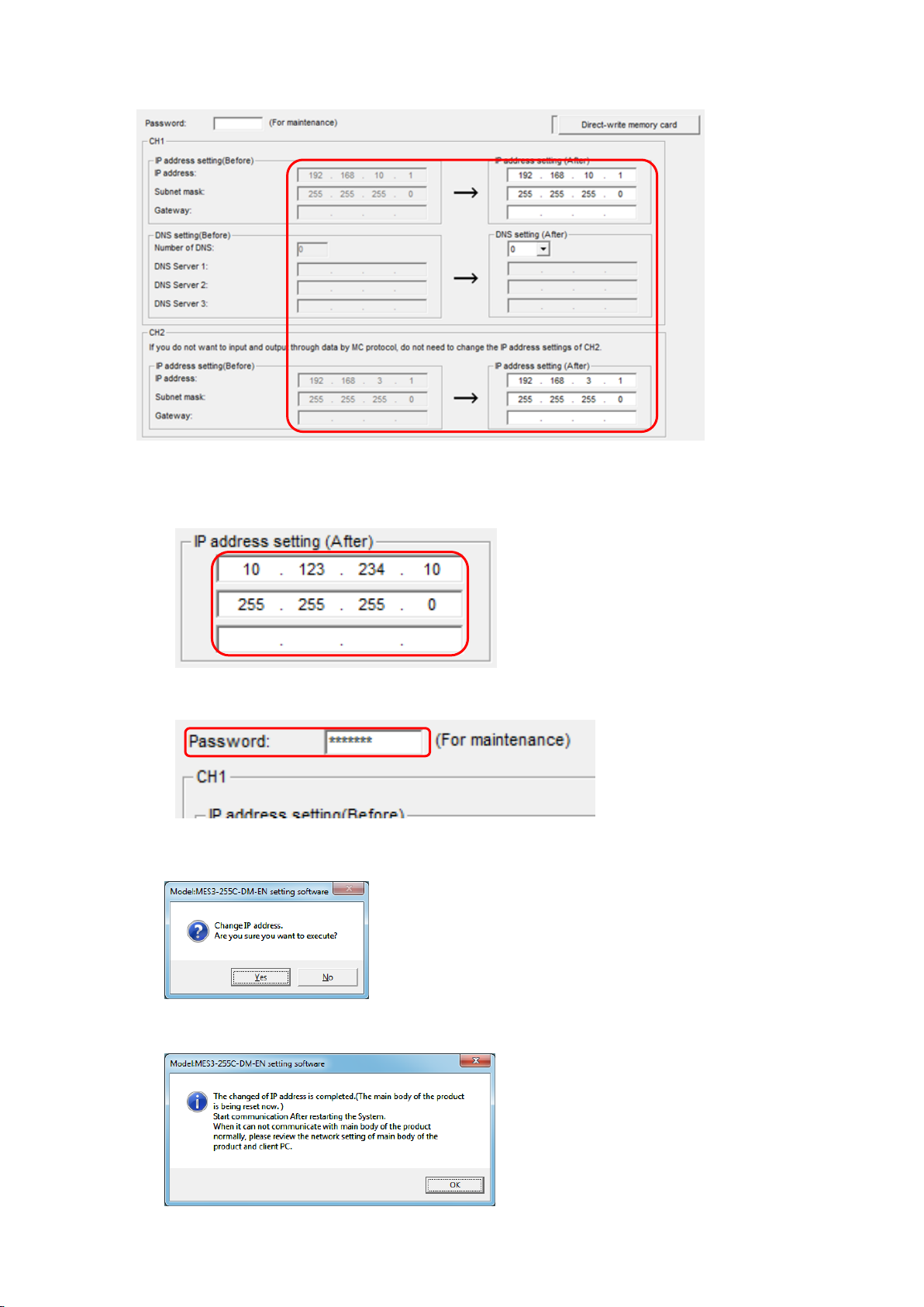
The network information currently set in EcoWebServer III is reflected to the IP address setting (Before) and IP
address setting (After) in CH1 and CH2.
(9) Change the IP address in IP address settings (new).
(The following figure shows an example of changing the IP address to 10.123.234.10. Type an IP address,
subnet mask, and default gateway to be used for operation.)
(10) Type a maintenance password (factory default: ecopass) in Password and click Apply.
In the confirmation dialog box that appears after you click Change, click Yes.
When the IP address configuration is complete, the following dialog box appears. Click OK.
Page 29

29
*1 After the IP address configuration is complete, EcoWebServer III is automatically reset. (After it is reset,
the new IP address settings take effect.)
*2 Resetting takes 1 to 8 minutes to complete. Check to see that resetting is complete and the "STA." LED
on the EcoWebServer III main unit turns on before starting communications.
*3 The values of IP address, Subnet mask, and Default gateway in the project information are also
automatically updated with the new values.
(11) After changing the IP address for the product, return the PC's IP address to its original address.
Page 30
30
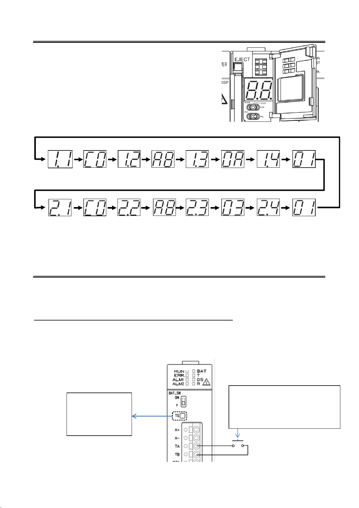
7.2 Checking the IP address
Hexadecimal: C0
Decimal: 192
Hexadecimal: A8
Decimal: 168
Hexadecimal: 0A
Decimal: 10
Hexadecimal: 01
Decimal: 1
Hexadecimal: C0
Decimal: 192
Hexadecimal: A8
Decimal: 168
Hexadecimal: 03
Decimal: 3
Hexadecimal: 01
Decimal: 1
DEMAND
Press the switch on the
hour or on the
half-hour of the time of
the electricity meter
under surveillance.
Time limit synchronization can be made easy
and accurate by extending the cable from the
TA and TB terminals to the electricity meter
under surveillance and short-circuiting them
while checking the time.
(1) Open the front cover on the server section, and set the MODE
switch to the "STOP" position.
(2) Set the RESET switch to the "SEL." position.
(3) After the "CF CARD" LED turns off, turn the RESET switch to the
"RES."
(4) After all the LEDs except the "POWER" LED on the power supply
section turn off, return the RESET switch to the central position.
(5) Wait until the product starts up and the IP address is displayed on the
7-segment LED at the front.
IP address display (Example of 192.168.10.1 set to CH1 and 192.168.3.1 set to CH2.)
(6) After you finish checking the IP address, turn the MODE switch to the "RUN" position.
7.3 Time limit synchronization of the demand surveillance section
(1) Press TS (time limit synchronization switch) to synchronize the time limit.
Press the TS switch in synchronization with the switching (on the hour or on the half-hour) of the time limit of the
transaction electricity meter.
* If the product is located at a distance from the transaction electricity meter:
The time limit can also be synchronized by short-circuiting TA and TB instead of pressing TS (time limit synchronization
switch).
Time limit synchronization can be facilitated by connecting a cable equipped with a push button to the TA and TB
terminals and extending it to near the transaction electricity meter.
Page 31
31
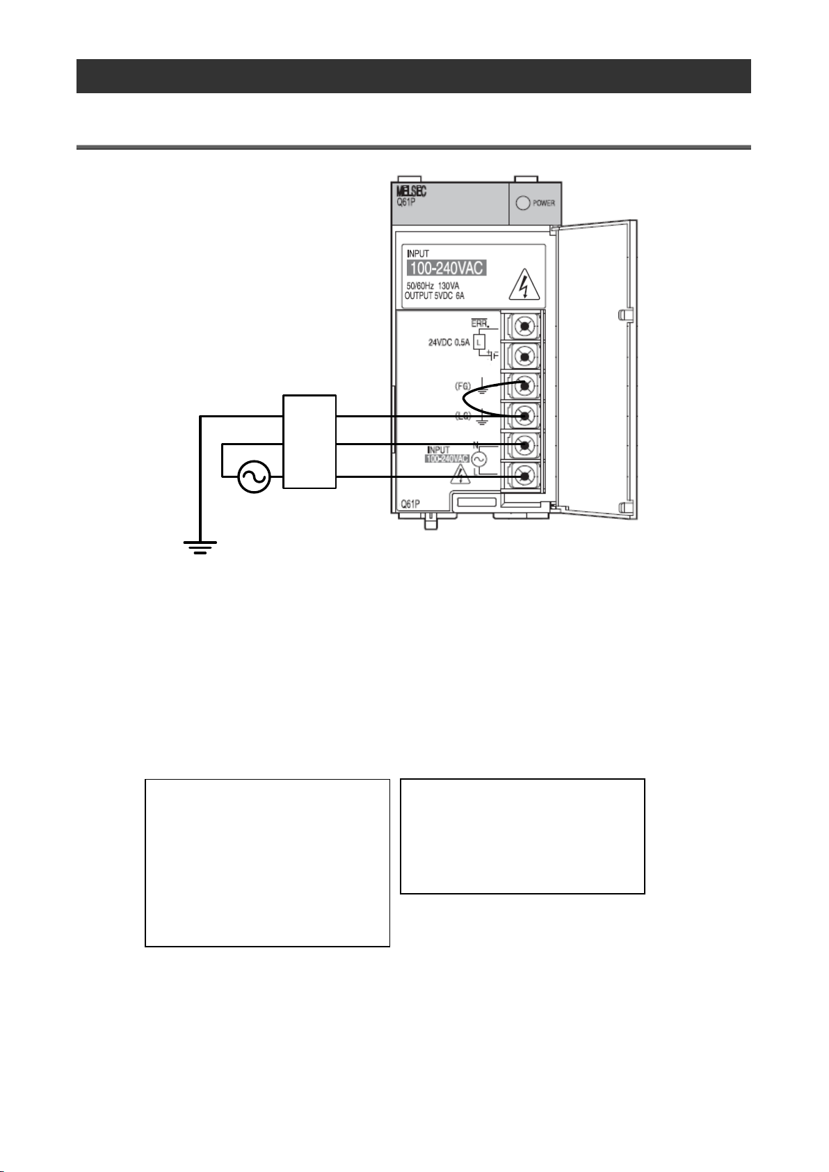
8. Connection Diagram
AC100 to 240V
D grounding
Noise
filter
Note
* Voyez les remarques sur la page 3.
* Fil sous tension N'est PAS permis.
* Taille de câble, regardez la page 3.
* FG, LG est réservé s exclusive aux bases
de classe D.
Note
* See page 3 for detailed cautions.
* Never work with live wires.
* Use electric wires of appropriate size.
See page 3 for information on wire size.
* Perform class D grounding dedicated for
the FG and LG terminals.
* Use the power terminals L and N via a
noise filter.
8.1 Power supply section (Section de l'alimentation électrique)
* An optional noise filter can be installed to the power source line in order to reduce noise more effectively.
<Recommended model>
Model: FN343-3/01 (Rated current: 3 A)
Manufacturer: SCHAFFNER
* Demand control section requires for additional power.
It is necessary to connect AC100 to 240V (+10%,-15%) 50/60Hz to V1,V2 in demand terminal block.
It is possible to take the power from the power supply section.
Do not use UPS, SAG and etc. to supply the power.
Software and data of EcoWebServerIII is being saved in compact flash card.
It might cause data corruption by a power failure or an instant power. Please consider UPS if the power failure
is frequently occurred. Please confirm the content to turn off EcoWebServerIII for maintenance. Procedure
refers to [Names and functions of parts].
.
Page 32
32
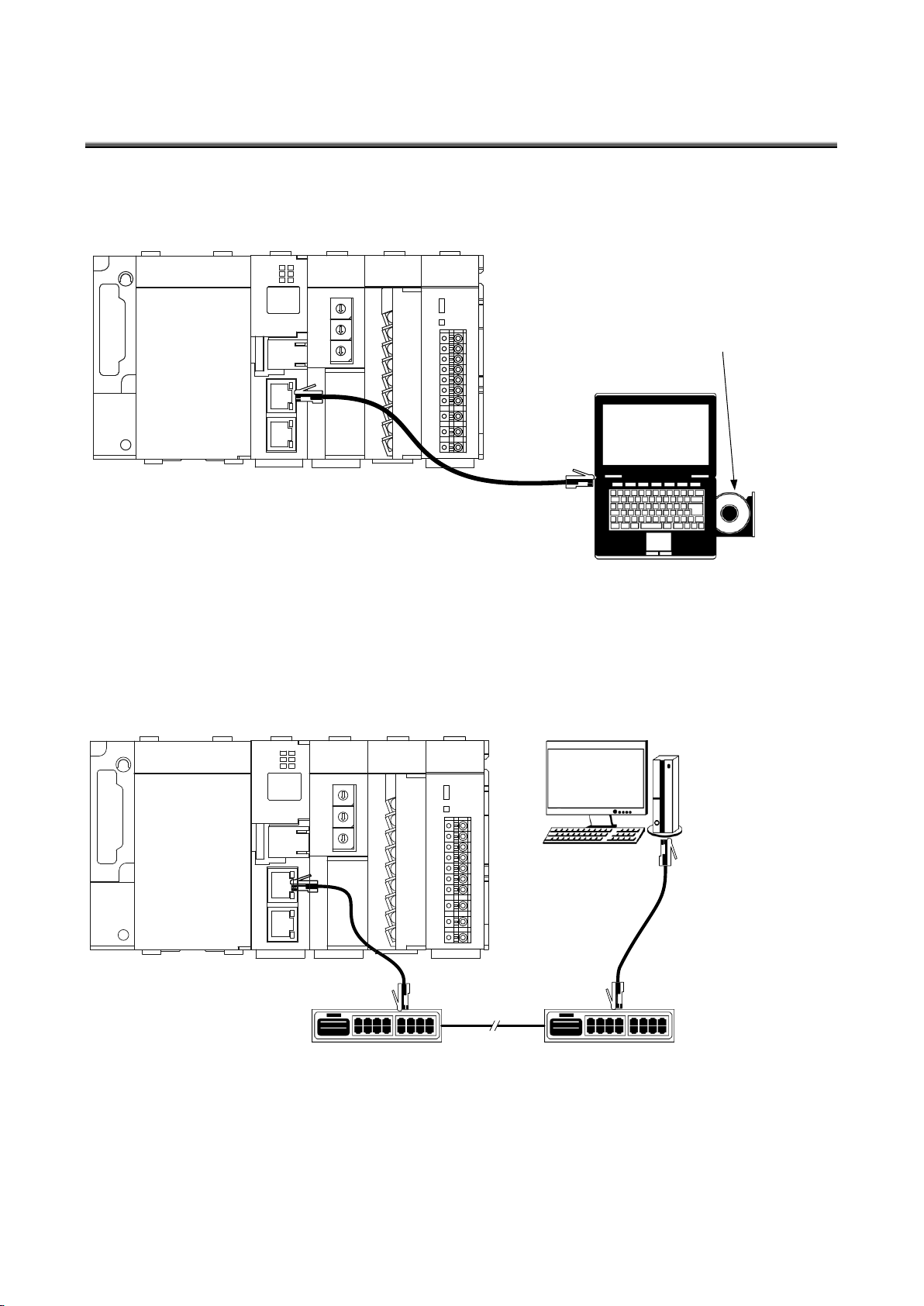
8.2 Ethernet communication section (CH1 for connection to PC)
CH
1
LAN cable
(Straight or crossover)
(Droit ou métissé)
PC
Supplied CD
(Setting software)
(Logiciel de réglages)
CH
2
CH
1
Hub(Hub)
Client PC
(PC clientèle)
LAN cable(Straight)
(Câble de LAN(Droit))
Hub(Hub)
Intranet LAN network
(Réseau d'intranet LAN)
CH
2
(Section de communication Ethernet)
8.2.1. For initial setting (IP address setting)
(Pour les réglages initiaux (adresse IP fixation))
8.2.2. For operation (Pour opération)
Page 33
33
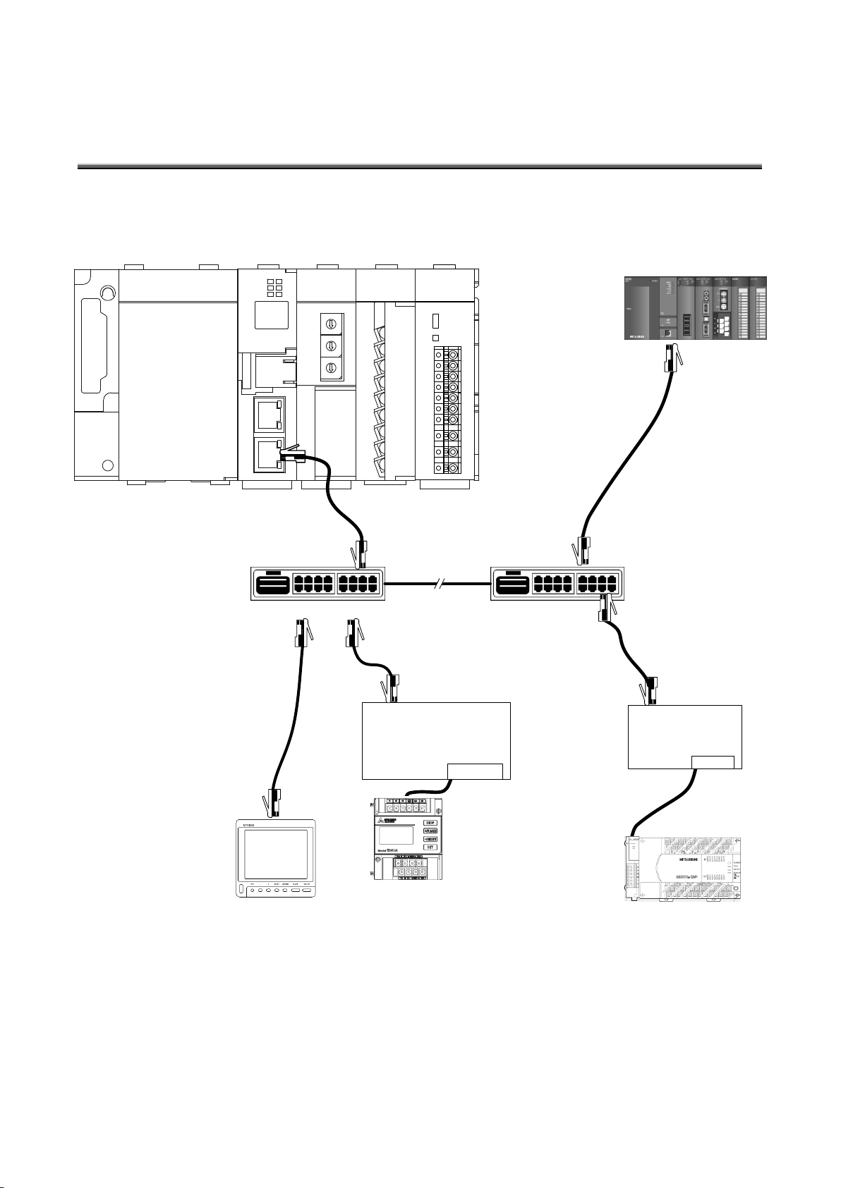
8.3 Ethernet communication section (CH2 for connection to programmable logic
Hub(Hub)
Connect to Ethernet port or
Ethernet unit of PLC
(Connectez au port Ethernet ou à l'unité
Ethernet de PLC)
LAN cable(Straight)
(Câble de LAN(Droit))
Hub(Hub)
Intranet LAN network
(Réseau d'intranet LAN)
Ethernet/Serial convertor
(Convertisseur Ethernet/Série)
Connect to link unit of PLC
(Connectez à l'unité de lien PLC)
LAN cable(Straight)
(Câble de LAN(Droit))
LAN cable(Straight)
(Câble de LAN(Droit))
CH
1
CH
2
Connect to Ethernet port of
MODBUS® TCP terminal
(Connecter au port Ethernet de
la terminal MODBUS® TCP)
MODBUS® TCP – MODBUS® RTU
convertor
(Convertisseur MODBUS® TCP –
MODBUS® RTU)
LAN cable(Straight or crossover)
(Câble de LAN(Droit ou métissé))
Connect to MODBUS® RTU
terminal
(Connectez-vous à la terminal
MODBUS® RTU)
LAN cable(Straight or crossover)
(Câble de LAN(Droit ou métissé))
controllers and MODBUS® terminals.)
(Section de communication Ethernet (CH2))
8.3.1. For operation (Pour opération)
* See the manual for the programmable logic controller for information on Ethernet connection of
programmable logic controllers and link connection of computers.
(*Voyez le mode d'emploi de PLC en détail.)
* Mitsubishi FX series programmable logic controllers cannot be connected directly to Ethernet.
An Ethernet/Serial communication converter is required.
(Série FX est seulement soutenue pour la communication en série au moyen de convertisseur
Ethernet/Série.)
* The Ethernet/Serial communication converter model that has been functionally verified is LINE EYE
SI-65.
* Operation of MODBUS® TCP – MODBUS® RTU convertor model that has been functionally verified is LINE
EYE SI-485MB.
Page 34
34
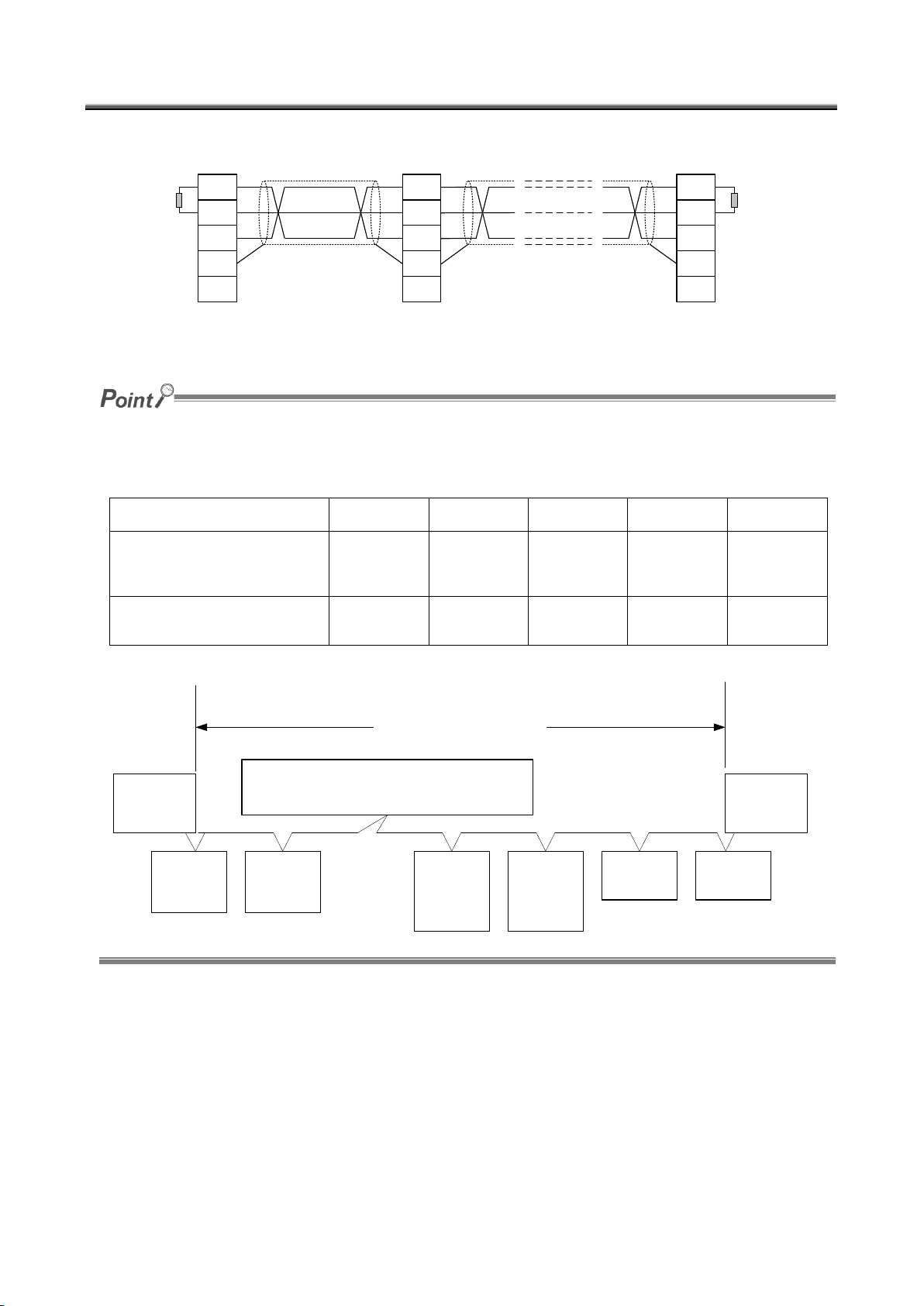
8.4 CC-Link communication section (Section de CC-Link communication)
DA
DB
DG
SLD
FG
DA
DB
DG
SLD
FG
DA
DB
DG
SLD
FG
(Blue)
(White)
(Yellow)
(Blue)
(White)
(Yellow)
(Blue)
(White)
(Yellow)
(Blue)
(White)
(Yellow)
Termination
resistor
(110 Ω, ½ W)
Termination
resistor
(110 Ω, ½ W)
CC-Link dedicated cable
CC-Link dedicated cable
Energy Saving Data Collection Server
(master station)
CC-Link slave station CC-Link slave station
Serveur collecte de données économie
d'énergie (station maître)
Station affranchie de CC-Link
Station affranchie de CC-Link
Résistance de
terminal
(110 Ω, ½ W)
Câble réservé à CC-Link
Câble réservé à CC-Link
Résistance de
terminal
(110 Ω, ½ W)
Blue: Bleu
White: Blanc
Yellow: Jaune
The maximum transmission distance depends on the CC-Link communication speed setting.
(Distance de transmission maximale compte sur la fixation de la vitesse de communication.)
Perform wiring according to the following table so that it will not exceed the maximum transmission distance.
(Réalisez le câblage selon la table suivante afin qu'il n'excède pas la distance de transmission maximale.)
Communication speed
(Vitesse de la communication)
156 kbps
625 bps
2.5 Mbps
5 Mbps
10 Mbps
Cable length between stations
(Longueur du câble entre les
stations)
20 cm or
longer
(20 cm ou
plus)
20 cm or
longer
(20 cm ou
plus)
20 cm or
longer
(20 cm ou
plus)
20 cm or
longer
(20 cm ou
plus)
20 cm or
longer
(20 cm ou
plus)
Max. transmission distance
(Distance de transmission
maximale)
1200 m
900 m
400 m
160 m
100 m
Termination
resistor
Résistance de
terminal
Remote
I/O station
Station I/O
isolée
Remote
I/O station
Station I/O
isolée
Remote
device
station
Station de
dispositif isolée
Energy Saving Data Collection Server
(master station)
Serveur collecte de données économie d'énergie (station maître)
Remote
device
station
Station de
dispositif isolée
Local
station
Station locale
Local
station
Station locale
Max. transmission distance
Distance de transmission maximale
Termination
resistor
Résistance de
terminal
Page 35
35
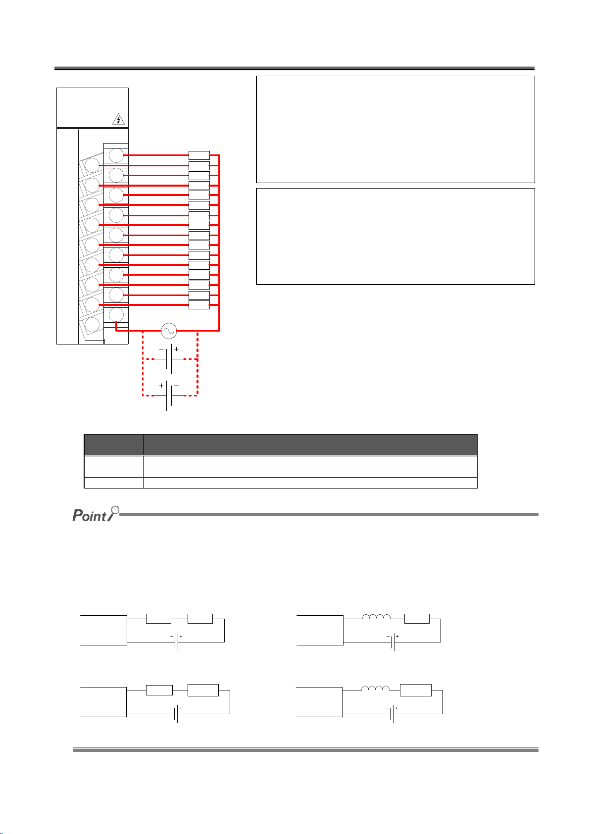
8.5 Contact output section (Section de sortie contact)
1
3
5
7
9
B
D
F
0
2
4
6
8
A
C
E
0 1 2 3 4 5 6 7
8 9 A B C D E F
COM
Load
Load
Load
Load
Load
Load
Load
Load
Load
Load
Load
Load
Load
Load
Load
Load
100/200 V AC
or 24 V DC
(100/200 V AC
ou 24 V DC)
Load: Charge
Terminal
symbol
Function
0 to 9, A to F
Contact relay output terminals 0 to 9, A to F
COM
Contact relay output common terminal (common for output terminals 0 to 9, A to F)
NC
(Unused)
When a counter or timer that uses a DC-DC converter is connected as a load, its inrush current should be below the
maximum load current of the contact output section.
(Si l'un comptoir ou chronomètre ce qu'il utilise un DC-DC transformateur sera connecté comme une charge, le
courant d'afflux doit être inférieur au courant de charge maximum de la section de contact de sortie.)
If the inrush current is larger, perform any one of the following to reduce the impact of the inrush current.
(Si le courant d'afflux est grand, réalisez l'un des suivants pour diminuer l'impact du courant d'afflux.)
Contact
output
section
Resistor
Load
Contact
output
section
Load
Inductance
Section de
sortie
contact
résistance
Charge
Section de
sortie
contact
Charge
Inducteur
Note
* Voyez les remarques sur la page 3.
* Pour empêcher le bruit d'induction, écartez les lignes de contrôle des
lignes électriques autant que possible.
* Taille de câble, regardez la page 3.
* Si COM sera connecté aux points plusieurs, terminaux doit être disposé
par client.
Note
* See page 3 for detailed cautions on installation of the product.
* To prevent induction noise, keep control lines as far away from power
lines as possible.
* Use electric wires of appropriate size. See page 3 for information on wire
size.
* Additional terminal blocks should be installed by the customer if more
contact points are connected to COM.
Page 36
36
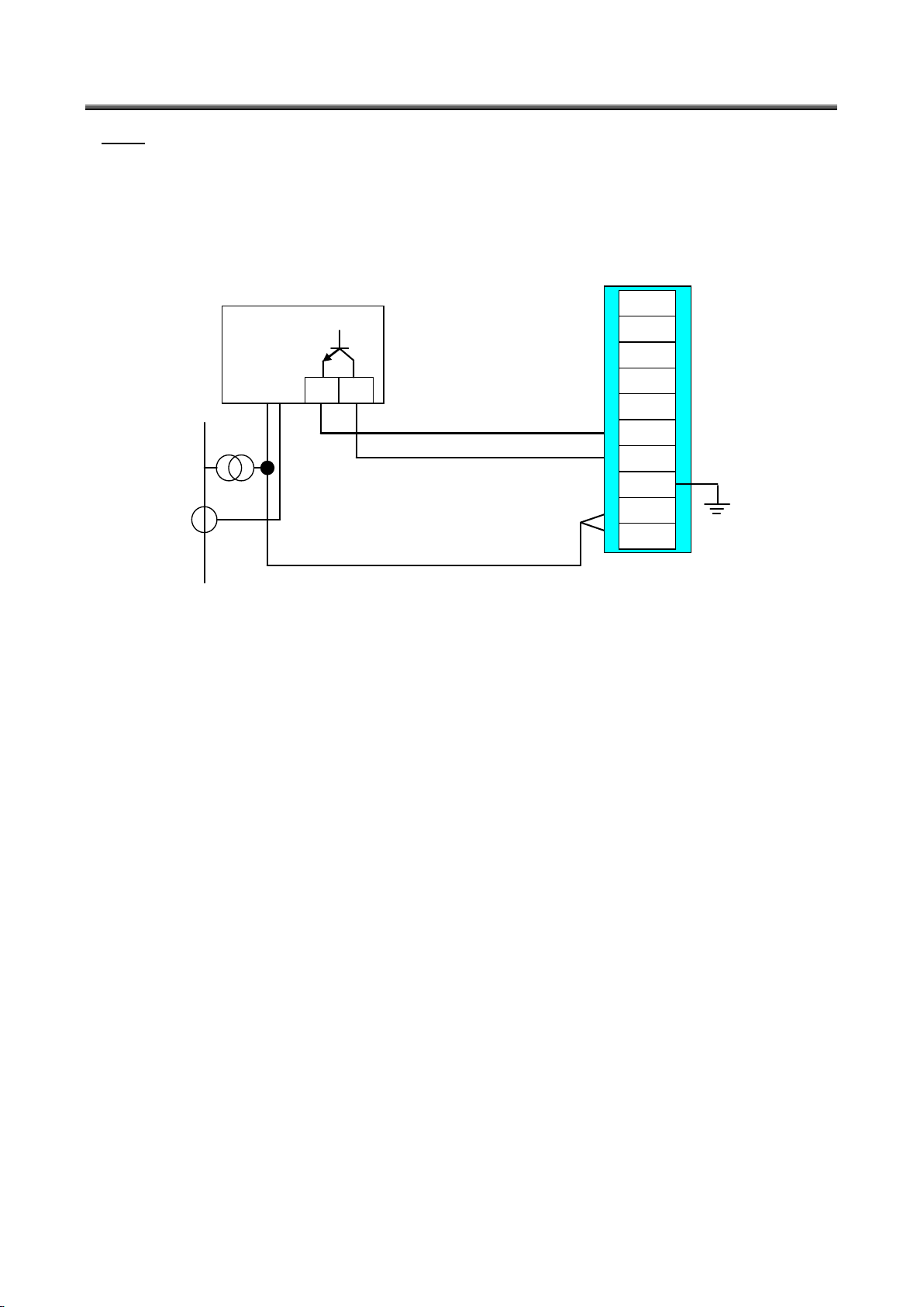
8.6 Demand surveillance unit section (Section de sortie contact)
Reference meter
C1A C1B
VT
CT
AC 100 V
Demand unit
V1
V2
A+
A-
TA
TB
RT1
RT2
RT3
E
Wiring
Perform wiring in accordance with the wiring diagram below.
For detailed specifications and usage, see Instruction Manual – Configuration.
Earth terminal is support to be wiring to earth. (Un-connected inside)
When an open-collector transmitter is used as a reference meter:
(This is an example for ME96SS series with option unit (model: ME-4210-SS96) in the following.)
Page 37
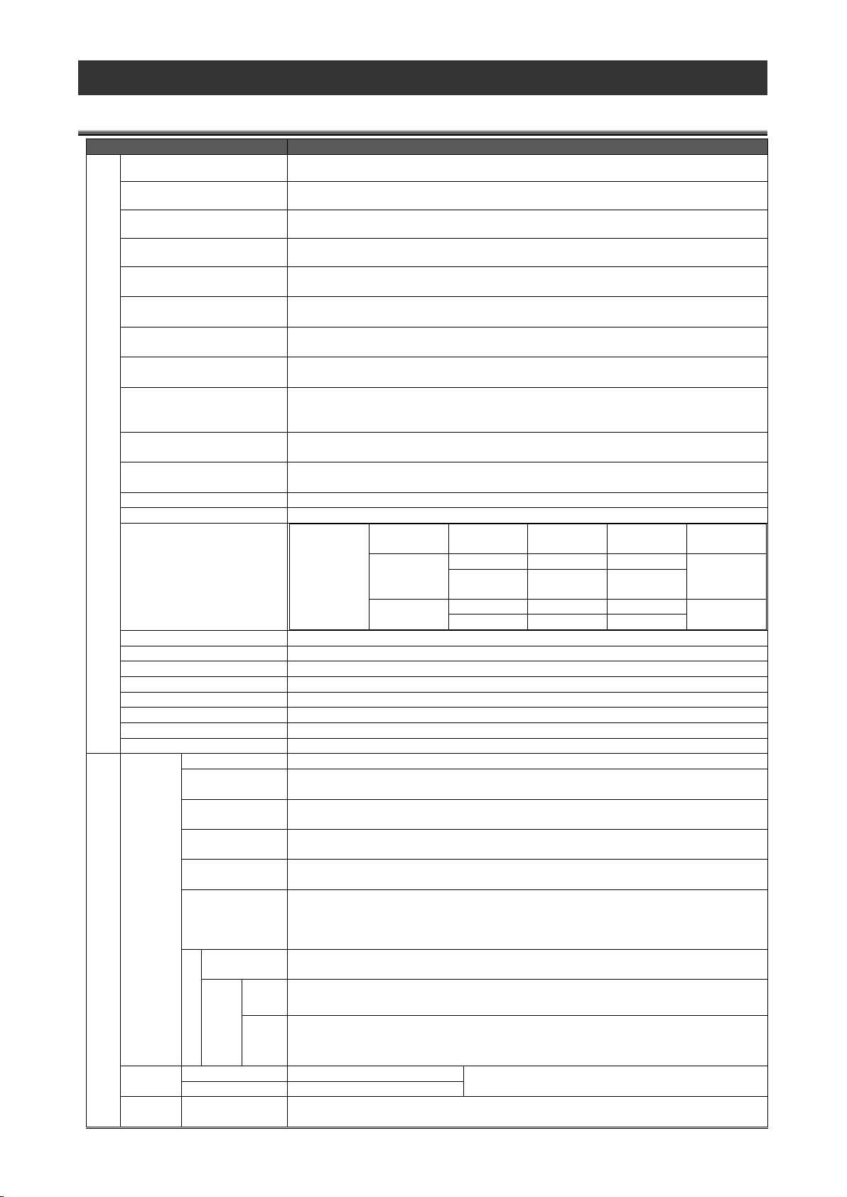
37
9. Specifications
Item
Specifications
Power supply section
Auxiliary power input
(Entrée d'alimentation électrique)
100 to 240 V AC (+10%, -15%)
Input frequency
(Fréquence d'entrée)
50/60 Hz (±5%)
Input voltage distortion
(Distorsion)
Within 5%
Consumption VA
(Consommation VA)
19 VA (at 110 V AC), 25 VA (at 220 V AC)
Inrush current
(Courant d'afflux)
20 A, 8 ms or less
(20 ms ou moins (100 V AC ou plus)
Allowable momentary power
interruption time
20 ms or less (100 V AC or higher)
Withstand voltage
Between all input/LG terminals and all output terminals
2,830 Vrms AC/3 cycles (altitude: 2,000 m)
Insulation resistance
10 MΩ or more by 500 V DC insulation tester at the same locations as for withstand
voltage
Noise immunity
- Noise voltage 1500 Vp-p, noise width 1 µs
Measured by noise simulator with a noise frequency of 25 to 60 Hz
- Noise voltage IEC61000-4-4, 2 kV
Operating ambient
temperature
0 to 55 ºC
Storage ambient
temperature
-25 to +75 ºC
Operating ambient humidity
5 to 95% RH
Storage ambient humidity
5 to 95% RH
Vibration resistance
Conforming
to JIS B
3502, IEC
61131-2
─
Frequency
Constant
acceleration
Half
amplitude
Sweep count
Intermittent
vibration
5 to 9 Hz
─
3.5 mm
10 times in
each axis X,
Y, Z
9 to 150 Hz
9.8 m/s2
─
Continuous
vibration
5 to 9 Hz
─
1.75 mm
─
9 to 150 Hz
4.9 m/s2
─
Impact resistance
Conforming to JIS B 3502, IEC 61131-2 (147 m/s2, 3 times in each axis X, Y, Z)
Operating atmosphere
No corrosive gas
Operating altitude
2000 m or below
Installation area
Inside a control panel
Overvoltage category(*1)
II or below
Contamination level(*2)
2 or below
Weight
0.9 kg
Fuse
Built-in (unreplaceable by user)
Server section
Ethernet
Interface
10BASE-T 100BASE-TX
Transmission
method
Baseband
Cascade
connection limit
4 levels max. (10BASE-T), 2 levels max. (100BASE-TX)
Max. segment
length
100 m
Compatible
connector
RJ45
Functions
supported
Autonegotiation
(10BASE-T/100BASE-TX automatically detected)
Auto MDIX function
(straight/crossover cable automatically detected)
Protocol
LAN CH1
HTTP (view by web browser), FTP (read time, file transfer),
SMTP (send mail), SNTP (set time)
client
Ethernet direct: QnA compatible 3E frame (ASCII)
Ethernet / Serial conversion time: A compatible 1C frame format 4 (ASCII)
server
3 E frame (binary) / 4 E frame (binary)
Clock
accuracy
0 to 55 ºC
Per day: -10.89 to +8.64 sec
Additional difference of ±0.5 seconds can be
produced during power outages.
25 ºC
Per day: -4.32 to +5.25 sec
Power-int
erruption
Backup data
Backed up by battery.
- Clock
9.1 Hardware specifications
Page 38
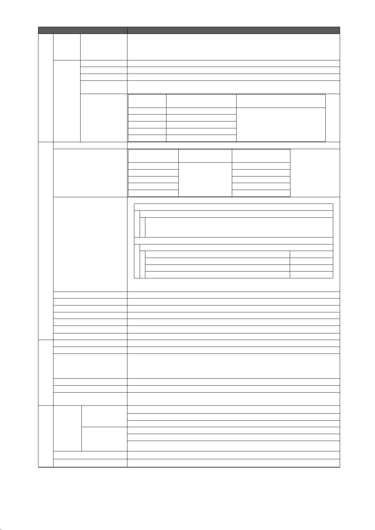
38
Item
Specifications
backup
(*4)
- Measured data for the last 1 hour
Backed up by nonvolatile memory card.
- Setting values
- Measured data except for the last 1 hour
Battery
Type
Lithium manganese dioxide primary battery
Initial voltage
3.0 V
Nominal current
1800 mAh
Life when in
storage
5 years at room temperature (actual service value)
Life when in use
Energized
time ratio
Guaranteed value
Guaranteed time after battery
error occurs
0%
13,700 hours, 1.57 years
600 hours, 25 days
30%
19,100 hours, 2.18 years
50%
25,800 hours, 2.96 years
70%
40,000 hours, 4.57 years
100%
43,800 hours, 5 years
CC-Link communication section
Transmission speed
156 kbps / 625 kbps / 2.5 Mbps / 5 Mbps / 10 Mbps
Max. overall cable length
(Max. transmission distance)
Communication
speed
Cable length
between stations
Max. overall cable
length
156 kbps
20 cm or longer
1200 m
625 kbps
900 m
2.5 Mbps
400 m
5 Mbps
160 m
10 Mbps
100 m
Max. number of connected
units
64 units under the following conditions.
1. Total number of stations
a + b × 2 + c × 3 + d × 4 ≤ 64
a: Number of units occupying 1 station, b: Number of units occupying 2
stations, c: Number of units occupying 3 stations, d: Number of units
occupying 4 stations
2. Number of connected units
16 × (A + D) + 54 × B + 88 × c ≤ 2304
A: Number of remote I/O station units
--- 64 units max.
B: Number of remote device station units
--- 42 units max.
C: Number of local station/intelligent device station units
--- 26 units max.
D: Number of reserved station units*
* Unregistered station numbers between the station number 1 and the last station
number are counted as reserved station units.
Communication method
Broadcast polling method
Synchronization method
Frame synchronous method
Encoding method
NRZI method
Transmission path type
Bus (RS-485)
Transmission format
HDLC compliant
Error control method
CRC (X16 + X12 + X5 + 1)
Connection cable
Ver. 1.10-compatible CC-Link dedicated cable
Number of output points
16 points
Insulation method
Relay insulation
Rated switching
voltage/current
24 V DC 2 A (resistance load)
240 V AC 2 A (COSφ=1)
(24 V DC 2 A (charge de résistance))
(240 V AC 2 A (COSφ=1))
/1 point, 8 A/1 common
(/1 point, 8 A/1 commun)
Min. switching load
5 V DC, 1 mA
Max. switching load
264 V AC 2 A, 125 V DC 2 A
Life
Mechanical: 20,000,000 times or more, electrical: 100,000 times or more at rated
switching voltage/current
Demand surveillance
section
Pulse
input/
Time limit
synchroni
sm signal
input
Dedicated
detection CT
Number of pulses: 50000 pulses/kWh
Pulse conditions:
Distance: 100 m or below (dedicated cable)
Pulse detector
Signal type: No-voltage normally-open contact/Open collector
Number of pulses: 50000, 12500, 10000, 2000
Pulse conditions: Pulse width, Pulse interval
Power frequency input
100-110 V AC, -15% +10%, 50/60 Hz
Contact output
No-voltage normally-closed contact, 250 V AC 3 A, 30 V DC 3 A
Page 39

39
*1 This refers to the assumed part of electric distribution where the device is to be installed within the area ranging from
public electric distribution to premises machinery. The measurement category II applies to devices power-supplied
from fixed equipment. The surge withstand voltage of devices whose rated voltage is up to 300 V is 2500 V. (IEC
60664-1)
*2 The index indicates the degree of occurrence of conductive substances in the device's operating environment.
Contamination level 2 means only occurrence of non-conductive substances. In this degree, however, temporary
conduction may be caused by accidental condensation. (IEC 60664-1)
*3 It is only for products with demand control function.
*4 If the product is reset when the battery's power-interruption backup cannot function due to the expiry of the backup
time or any other causes, the time is initialized to the default value (0:00, 1/1/2002). If you change the time of the
product in this state, measured data may be deleted. Therefore, be sure to collect necessary measured data before
changing the time. For details on data collection, see "4.7.1 Maintenance, Collecting data" in Instruction Manual –
Configuration.
*5 For UL/c-UL standard, please use the copper conductors wire which temperature rating is 60 ºC /75 ºC.
Page 40
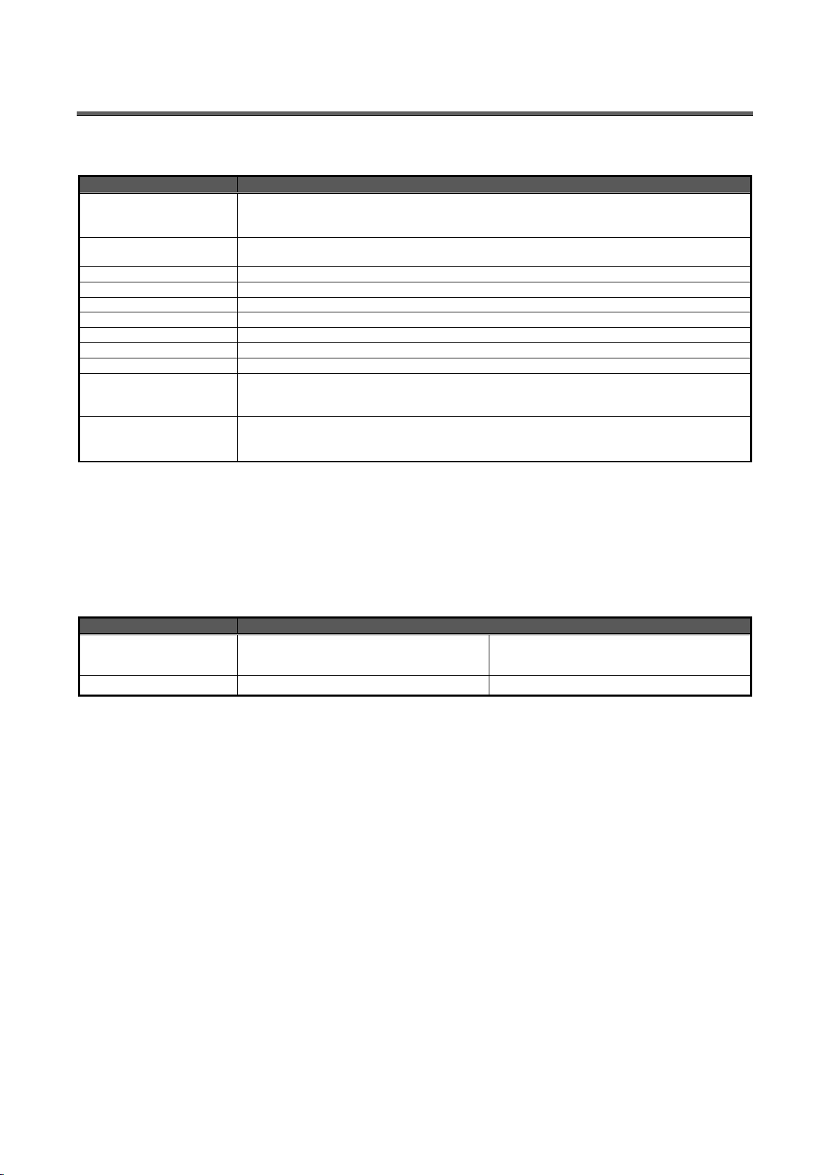
40
Item
Description
OS (basic software)
Microsoft® Windows® 7 Professional (32-bit or 64-bit) (English version) SP1
Microsoft® Windows® 8.1 Pro (32-bit or 64-bit) (English version)
Microsoft® Windows® 10 Pro (32bit, 64bit) (English version)
CPU
1 GHz or higher Pentium® processor, or compatible microprocessor
(DOS/V compatible)
Memory *1
1 GB or more
Hard disk *1
Save data collected by EcoWebServerIII to PC, enough disk space for the data is required
CD drive
One or more drives (required to install the setting software)
Display resolution
1,280 × 1,024 pixels or more
Display color
65,536 colors or more
Input device
A mouse and a keyboard
English input system
The system included in OS (English version only)
External interface
10BASE-T/100BASE-TX
Memory card reader (when writing / reading / confirming a project via drive
by setting software)
Web browser *2
Microsoft Internet Explorer® 9 (32-bit), 10 (32-bit), or 11(32-bit)
Microsoft Edge
Google Chrome
Item
Description
OS
Android6.0
iOS10
Web browser *4
Google Chrome
Safari
9.2 Operating environment
The system environment requirements for this software to properly operate as follows:
[PC]
*1 Note that the required memory and free space of hard disk vary depending on the system
environment.
*2 Operation check for Microsoft Edge is done in version 38.
Operation check for Google Chrome is done in version 54.
[Tablet *3]
*3 Tablet is only for browsing the web screen. Setting software cannot be used on the tablet.
*4 Operation check for Google Chrome is done in version 54.
Operation check for Safari is done in version 10.
Page 41
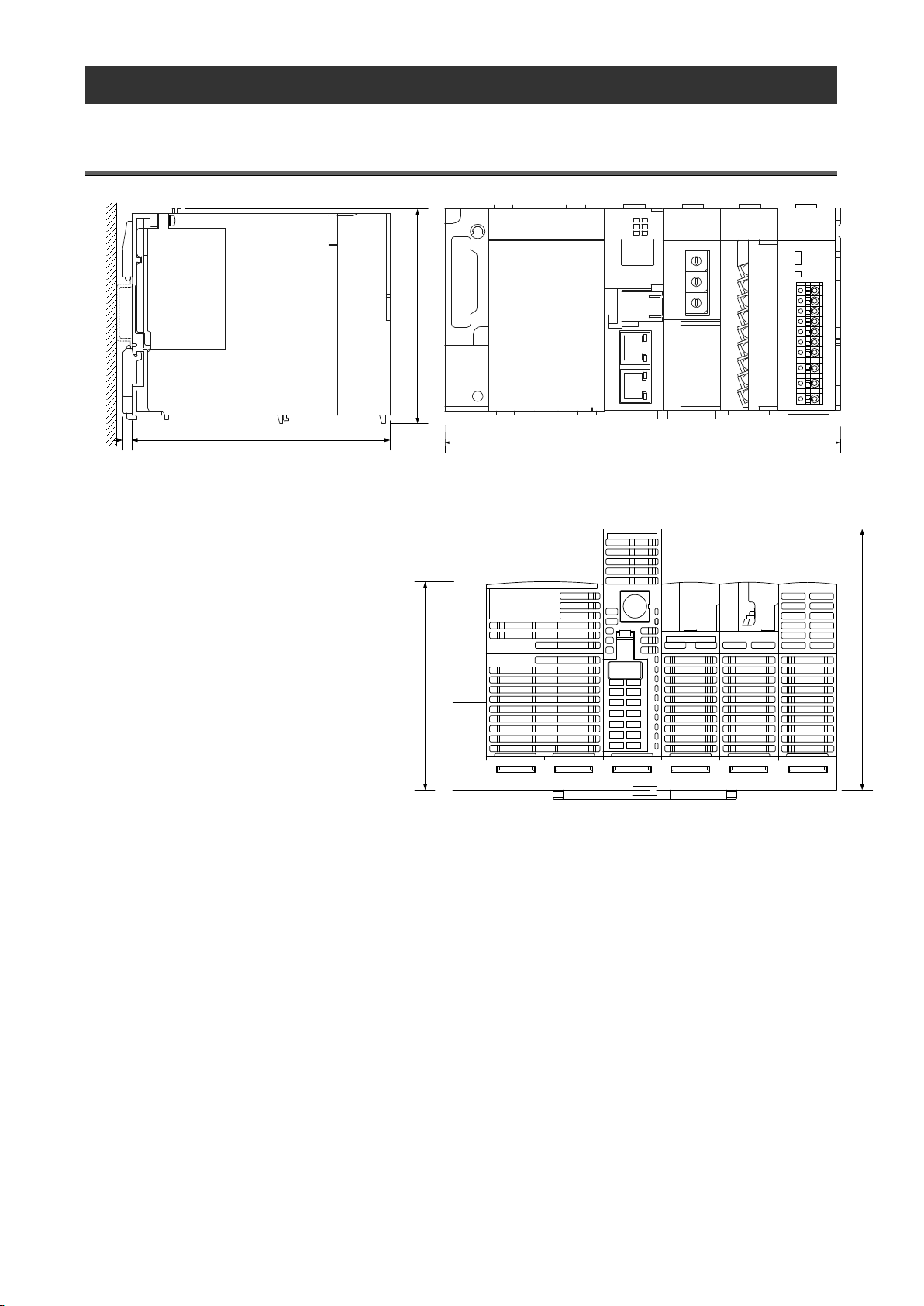
41
10. Outline Dimensions
189
Front
104
122.54.5
Side
122.5
97.5
Bottom
10.1 Outline dimensions
(Unit: mm)
Page 42
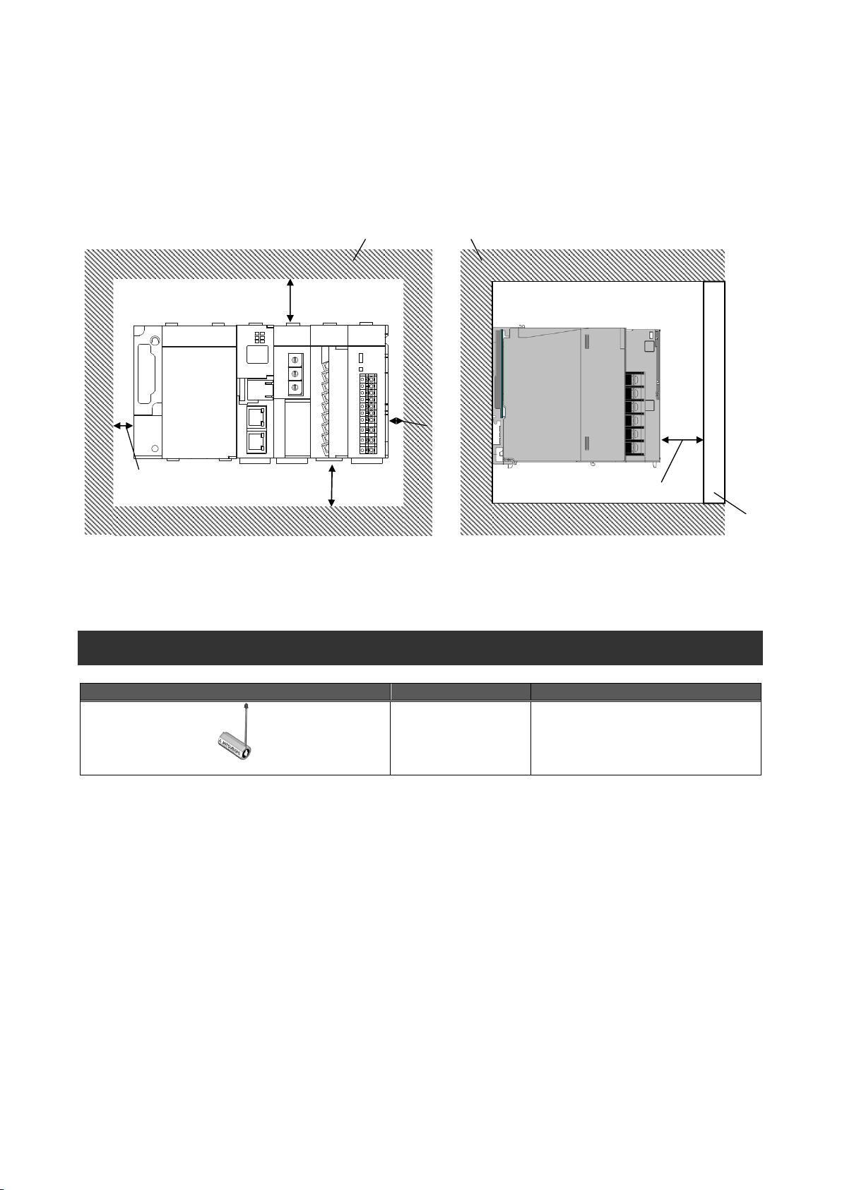
42
10.2 Installation conditions
The top of panel, wiring duct, or component positions are indicated.
80mm or more
door
*1 This length applies when the height of the wiring duct is 50mm or less. If not, the length should be 40mm or more.
30mm or more
30mm or more*1
10mm or more
5mm
or more
Item
Model
Note
Replacement battery(Server section)
Q6BAT
Recommended replacement time:
3 years
The following figures show the installation conditions taking heat dissipation into account. Sufficient space must also be
provided under the product for battery replacement.
When EcoWebServerIII is superimposed on the up and down, please keep the dissipation to be 60mm(30mm×2).
*1 It is no problem to remove the LAN port cap during the operating.
11. Options
For inquiries on the replacement battery, contact the dealer where you purchased this product.
Page 43
43
12. Troubleshooting
Symptom
Check item
The POWER lamp on the
power supply section does
not turn on.
Is the power supply (100 to 240 V AC, 50/60 Hz) properly connected between L
and N on the terminal block of the power supply section?
Is there any short-circuit or break in the power line?
The "ERR." LED on the
CC-Link communication
section is lighting or blinking.
Is there any error in communication with CC-Link terminal devices? Check
whether CC-Link terminal devices, CC-Link station numbers and CC-Link baud
rate are properly configured and communication cables and termination resistors
are properly connected.
The "ERR." LED on the
server section is lighting.
The battery is at the end of its life. Replace the battery.
(See 6.2 Replacing the battery.)
Is the battery connected?
The "STA." LED on the
server section is blinking for
a long time.
The data in the memory card is being restored during startup. The product starts
up normally after a few minutes.
"E0" is displayed on the
7-segment LED on the
server section.
AC100 to 240V (+10%,-15%) 50/60Hz is not connected to V1,V2 in demand
terminal block. It is possible to take the power from the power supply section.
"E1" is displayed on the
7-segment LED on the
server section.
Access to the internal memory has failed.
Reset the product.
"E2" is displayed on the
7-segment LED on the
server section.
Access to the CompactFlash memory card has failed.
Reset the product.
"E3" is displayed on the
7-segment LED on the
server section.
Automatic time adjustment with the SNTP server has failed.
Check whether normal communication can be established with the SNTP server
or settings in the SNTP server are correct.
"E4" is displayed on the
7-segment LED on the
server section.
File transfer to the FTP server has failed.
Check whether normal communication can be established with the FTP server or
settings in the FTP server are correct.
The indication rotates on the
7-segment LED on the
server section.
Is any CompactFlash card other than that supplied with the product connected?
Only the supplied CompactFlash card can be used. Connect the supplied card.
Please compare CompactFlash and
the right side of main product by the
sheet in the right.
If the product gives off abnormal noise, smell, smoke or heat, turn the power off immediately.
Check the following items for troubleshooting.
If you cannot solve your trouble in accordance with the check items above, contact your supplier or us.
Page 44
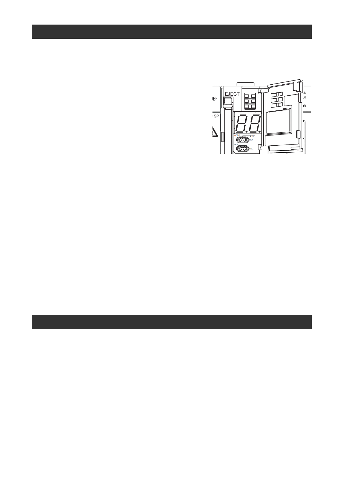
44
13. Initialization of Main Unit Memory
The main unit memory requires initialization when you use the product for the first time or when you keep the product
nonenergized for an extended period of time with the battery exhausted or disconnected (“01” blinks on the 7-segment
LED of the server section at startup).
(1) Check that the main unit is turned off.
(2) Install the battery.
(3) Open the front cover on the server section, and set the
MODE/STOP/RUN switch to the “STOP” position.
(4) Turn the main unit on with the MODE/STOP/RUN switch in the
“MODE” position.
(5) After the “MODE” LED lights orange and “00” is displayed on the
7-segment LED, return the MODE/STOP/RUN switch to the “STOP” position.
(6) Turn the RESET/SELECT switch to the “SEL.” position 9 times to see “11” on the 7-segment LED.
(7) Turn the MODE/STOP/RUN switch to the “RUN” position. The “RUN” LED blinks and initialization of the main unit
memory starts.
(8) After the “RUN” LED turns off and “00” is displayed on the 7-segment LED, turn the RESET/SELECT switch to the
“RES.” position.
(9) Turn the RESET/SELECT switch to the “RES.” position to see all the LEDs except the “POWER” LED on the power
supply section turn off, and return the RESET/SELECT switch to the central position.
(10) Formatting of the main unit memory starts. (The “RUN” LED blinks and the “STA.” LED blinks green.)
(11) After the “MODE” LED starts blinking green, turn the RESET/SELECT switch to the “RES.” position to see all the
LEDs except the “POWER” LED on the power supply section turn off, and return the RESET/SELECT switch to the
central position.
This completes the initialization of the main unit memory. Set up an IP address.(See “8.1 Setting IP address”.)
14. Warranty
For technical and non-technical inquiries about the product, contact the nearest Mitsubishi office or dealer.
This document and product have undergone strict quality control and inspection before delivery, but in the unlikely
event that the document or product is defective in manufacture, our company shall provide replacement. Contact the
dealer where you purchased this product. However, this warranty does not apply to the product or document that has
been damaged by acts of God or misapplication.
Our company shall not be liable for any damages arising out of your or third parties' system troubles, legal problems,
misapplication, failures during use, or any other defects.
The product is warranted for a period of less than one (1) year from the date of your purchase or from the date of
delivery to your specified location or within eighteen (18) months from the date of shipment from our factory (from the
month and year of manufacture), whichever is less.
If any of the following applies, however, the cost of repair or replacement shall be charged even during the warranty
period:
(1) Any malfunction arising from misapplication
(2) Any malfunction arising from misoperation
Repair or replacement made after the expiration of the warranty period shall be subject to charges.
The warranty period shall not be renewed after repair.
Page 45
45
Software License Agreement
This "Software License Agreement" (hereinafter referred to as "the Agreement") is applicable to the relevant software
(hereinafter referred to as "the Software") manufactured and sold by the Mitsubishi Electric Corporation (hereinafter
referred to as "Mitsubishi Electric"). Software means all programs on the recording media and all related documents.
Article 1 (License of use)
Mitsubishi Electric shall hereunder agree to grant the user the license to use the Software, and the user shall accept all
provisions stated below and agree not to assign such license of use to anyone other than contractors and not to possess
an exclusive license of use.
Article 2 (Reproduction of the Software)
The user must not reproduce all or part of the Software, except for the following:
(1) The reproduction of the Software is only allowed when this is for the security of the Software and the use of such
reproduction is limited to the designated computer. This shall only apply to the software that has been designed to enable
the reproduction of the Software.
Article 3 (Use on computers other than the designated computer)
The Software shall not be used on computers other than the designated computer. However, if any of the following events
occurs, the Software can temporarily be used on a computer other than the designated computer, for the period until such
event ceases to exist:
(1) The designated computer cannot be used due to the work for maintenance, adjustment, failure, etc., or
(2) The installation of the designated computer is not completed.
Article 4 (Limitation of liability)
(1) Mitsubishi Electric shall not guarantee that the Software is suitable or useful for the specific purpose intended by the
user.
(2) Mitsubishi Electric shall assume no liability for any damage to the user or any third party's claim against the user,
arising from the execution of the license of use granted to the user under the Agreement.
Article 5 (Alteration of the Software by user)
Any modification of the Software by the user shall not be allowed without written permission from Mitsubishi Electric.
Mitsubishi Electric shall assume no responsibility for the Software that has been modified by the user.
Article 6 (Copyright)
The copyright to the Software shall belong to the Mitsubishi Electric. The copyright to any reproductions described in
Article 2 shall also belong to Mitsubishi Electric. However, the recording media on which the Software is recorded shall not
belong to Mitsubishi Electric.
Article 7 (Confidentiality)
The user shall keep confidential, and must not disclose, the Software, its reproductions, and the materials related to these.
The user must not leak to a third party any of Mitsubishi Electric's business secrets that the user may get to know under
the Agreement.
Article 8 (Duration of the Agreement)
The Agreement shall come into force when the user agrees to the Agreement and installs the Software, and shall continue
in force for the duration until the Agreement becomes invalid due to any of the following:
(1) The user can terminate the license of use, within one (1) month after written notice is given to Mitsubishi Electric.
(2) Mitsubishi Electric can terminate the license of use, if the user violates the Agreement.
Article 9 (Domestic use only)
The user must not take the Software out of Japan, or send it to any area outside Japan, without prior written permission
from Mitsubishi Electric.
Article 10 (Termination)
When the license of use under the Agreement is terminated, the original Software, and all its reproductions, printed
materials, etc. shall be returned to, or a document proving that these are destroyed shall be sent to, Mitsubishi Electric,
within one (1) month from the date of such termination. All costs for such return or destruction shall be incurred by the
user.
Page 46
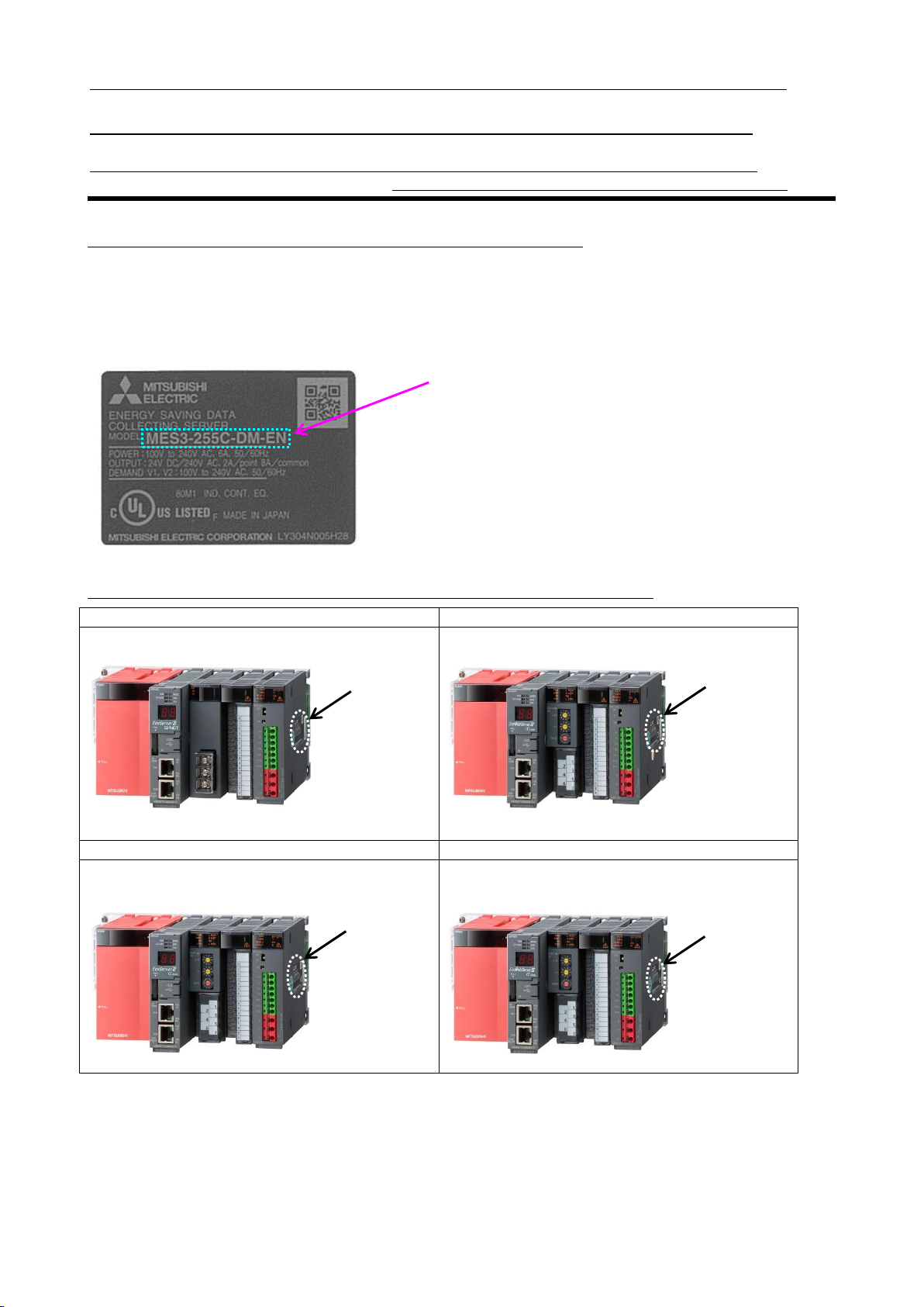
■MES3-255B-DM
■MES3-255C-DM-CN
本製品の定格銘板は右側面にあります。
本产品的额定铭板在产品的右侧面。
■MES3-255C-DM
■MES3-255C-DM-EN
本製品の定格銘板は右側面にあります。
The rating label can be found on the right side of the
product.
额定铭板
the rating label
定格銘板
定格銘板
形名 / 型号 / Model
三菱省エネデータ収集サーバEcoServerⅢ(MES3-255B-DM/MES3-255C-DM)定格銘板位置について
三菱节能数据收集服务器EcoWebServerⅢ(MES3-255C-DM-CN) 关于额定铭板的位置
Mitsubishi Energy Saving Data Collecting Server EcoWebServerⅢ(MES3-255C-DM-EN)
additional information on the place of the rating label
定格銘板例 / 额定铭板参考例 / Example of the rating label
MES3-255C-DM-EN の例です。
以 MES3-255C-DM-EN 为例。
Example of MES3-255C-DM-EN is shown below.
定格銘板位置 / 关于额定铭板的位置 / The place of the rating label
46
Page 47

Trademarks
Microsoft®, Windows®, Windows Vista®, Windows®7, Windows®8.1, Windows®10,and Internet
Explorer® are trademarks, registered trademarks and products of Microsoft Corporation in the United
States and/or other countries.
, all Java-based trademarks and logos are registered trademarks of Oracle Corporation and
its affiliated companies in the United States and/or other countries.
iOS is a registered trademark of Cisco Corporation in the United States.
Android, Chrome is a registered trademark of Google Inc.
Safari is a registered trademark of Google Inc.
Ethernet is a registered trademark of Xerox Corporation in the United States.
MODBUS® is a registered trademark of Schneider Automation Inc.
QR Code is a registered trademark of Denso Wave Incorporated.
EcoWebServer is a registered trademark of Mitsubishi Electric Corporation.
Other companies and product names in the manual are registered trademarks or trademarks of their
respective owners.
Trademark symbols such as "TM", "®" etc. may not be specified.
47
Page 48
New publication effective Apr.2018
Specifications are subject to change without notice.
HEAD OFFICE: TOKYO BUILDING, 2-7-3, MARUNOUCHI, CHIYODA-KU, TOKYO 100-8310, JAPAN
Mitsubishi Energy Saving Data Collecting Server
Country/Region
Corporation Name
Address
Telephone
Australia
Mitsubishi Electric Australia Pty. Ltd.
348 Victoria Road, Rydalmere, N.S.W. 2116, Australia
+61-2-9684-7777
Bangladesh
PROGRESSIVE TRADING CORPORATION
HAQUE TOWER,2ND FLOOR,610/11,JUBILEE ROAD, CHITTAGONG, BANGLADESH
+880-31-624307
ELECTRO MECH
AUTOMATION& ENGINEERING LTD.
SHATABDI CENTER, 12TH FLOOR, SUITES:12-B, 292, INNER CIRCULAR ROAD, FAKIRA POOL,
MOTIJHEEL, DHAKA-1000, BANGLADESH
+88-02-7192826
Belarus
Tehnikon
Oktyabrskaya 19, Off. 705, BY-220030 Minsk, Belarus
+375 (0)17 / 210 46 26
Belgium
Koning & Hartman B.V.
Woluwelaan 31, BE-1800 Vilvoorde, Belgium
+32 (0)2 / 2570240
Brazil
Mitsubishi Electric Do Brasil Comercio E Servicos
Ltda.
Av. Adelino Cardana, 293 -21 and. - Bethaville, 06401-147, Barueri/SP - Brasil
+55-11-4689-3000
Cambodia
DHINIMEX CO.,LTD
#245, St. Tep Phan, Phnom Penh, Cambodia
+855-23-997-725
Chile
Rhona S.A.
Vte. Agua Santa 4211 Casilla 30-D (P.O. Box) Vina del Mar, Chile
+56-32-2-320-600
China
Mitsubishi Electric Automation (China) Ltd.
Mitsubishi Electric Automation Building, No.1386 Hongqiao Road, Shanghai,200336
+86-21-2322-3030
Mitsubishi Electric Automation (China) Ltd.
North China Branch
9/F, Office Tower1 Henderson Centre 18 Jianguomennei Dajie DongCheng district BeiJing 100005
+86-10-6518-8830
Mitsubishi Electric Automation (China) Ltd.
NorthEast China Branch
Room2302,President Building Tower C,No.69 Heping North Avenue, Heping District,Shenyang,110003
+86-24-2259-8830
Mitsubishi Electric Automation (China) Ltd.
South China Branch
Room 2512--2516, Great China International Exchange Square, Jintian Rd.S., Futian District,
Shenzhen, 518034
+86-755-2399-8272
Mitsubishi Electric Automation (China) Ltd.
South China Branch
Room 1609, North Tower, The Hub Center, No.1068, Xing Gang East Road, Haizhu District,
GuangZhou, China 510335
+86-20-8923-6730
Mitsubishi Electric Automation (China) Ltd.
SouthWest China Branch
1501,1502,1503,15F,Guang-hua Centre,Block C,NO.98 Guang Hua North 3th Road Chengdu,610000
+86-28-8446-8030
Mitsubishi Electric Automation (Hong Kong) Ltd.
20/F, Cityplaza One, 1111 king's Road, Taikoo shing, Hong Kong
+852-2510-0555
Colombia
Proelectrico Representaciones S.A.
Carrera 42 # 75-367 Bod 109 Itagui Colombia
+57-4-4441284
Czech Republic
AUTOCONT CONTROL SYSTEMS S.R.O
Technologická 374/6, CZ-708 00 Ostrava - Pustkovec
+420 595 691 150
Denmark
BEIJER ELECTRONICS A/S
LYKKEGARDSVEJ 17, DK-4000 ROSKILDE
+45 (0)46/ 75 76 66
Egypt
Cairo Electrical Group
9, Rostoum St. Garden City P.O. Box 165-11516 Maglis El-Shaab,Cairo - Egypt
+20-2-27961337
France
Mitsubishi Electric Europe B.V.
25, Boulevard des Bouvets, F-92741 Nanterre Cedex
+33 (0) 1 / 55 68 55 68
Germany
Mitsubishi Electric Europe B.V.
Mitsubishi-Electric-Platz 1, 40882 Ratingen, Germany
+49 (2102) 4860
Greece
KALAMARAKIS - SAPOUNAS S.A.
IONIAS & NEROMILOU STR., CHAMOMILOS ACHARNES, ATHENS, 13678 Greece
+30-2102 406000
UTECO
5, MAVROGENOUS STR., 18542 PIRAEUS, Greece
+30-211-1206-900
Hungary
Meltrade Ltd.
Fertö utca 14. HU-1107 Budapest, Hungary
+36 (0)1-431-9726
India
Mitsubishi Electric India Private Limited
2nd Floor, Tower A&B, Cyber Greens, DLF Cyber City, DLF Phase-III, Gurgaon - 122 022 Haryana, India
+91-124-4630300
Indonesia
PT.Mitsubishi Electric Indonesia
Gedung Jaya 8th floor, JL.MH. Thamrin No.12 Jakarta Pusat 10340, Indonesia
+62-21-3192-6461
P. T. Sahabat Indonesia
P.O.Box 5045 Kawasan Industri Pergudangan, Jakarta, Indonesia
+62-(0)21-6610651-9
Ireland
Mitsubishi Electric Europe B.V.
Westgate Business Park, Ballymount, IRL-Dublin 24, Ireland
+353 (0)1-4198800
Israel
Gino Industries Ltd.
26, Ophir Street IL-32235 Haifa, Israel
+972 (0)4-867-0656
Italy
Mitsubishi Electric Europe B.V.
Viale Colleoni 7, I-20041 Agrate Brianza (MI), Italy
+39 039-60531
Kazakhstan
Kazpromavtomatika
ul. Zhambyla 28, KAZ - 100017 Karaganda
+7-7212-501000
Korea
Mitsubishi Electric Automation Korea Co., Ltd
9F Gangseo Hangang xi-tower, 401 Yangcheon-ro, Gangseo-gu, Seoul 07528 Korea
+82-2-3660-9572
Laos
AROUNKIT CORPORATION
IMPORT- EXPORT SOLE CO.,LTD
SAPHANMO VILLAGE. SAYSETHA DISTRICT, VIENTIANE CAPITAL, LAOS
+856-20-415899
Lebanon
Comptoir d'Electricite Generale-Liban
Cebaco Center - Block A Autostrade Dora, P.O. Box 11-2597 Beirut - Lebanon
+961-1-240445
Lithuania
Rifas UAB
Tinklu 29A, LT-5300 Panevezys, Lithuania
+370 (0)45-582-728
Malaysia
Mittric Sdn Bhd
No. 5 Jalan Pemberita U1/49, Temasya Industrial Park, Glenmarie 40150 Shah Alam,Selangor, Malaysia
+603-5569-3748
Malta
ALFATRADE LTD
99 PAOLA HILL, PAOLA PLA 1702, Malta
+356 (0)21-697-816
Maroco
SCHIELE MAROC
KM 7,2 NOUVELLE ROUTE DE RABAT AIN SEBAA, 20600 Casablanca, Maroco
+212 661 45 15 96
Mexico
Mitsubishi Electric Automation, Inc.
Mariano Escobedo 69, Col. Zona Industrial, Tlalnepantla, MEX - 54030 - MX
+55-3067-7500
Myanmar
Peace Myanmar Electric Co.,Ltd.
NO137/139 Botahtaung Pagoda Road, Botahtaung Town Ship 11161,Yangon,Myanmar
+95-(0)1-202589
Nepal
Watt&Volt House
KHA 2-65,Volt House Dillibazar Post Box:2108,Kathmandu,Nepal
+977-1-4411330
Netherlands
Imtech Marine & Offshore B.V.
Sluisjesdijk 155, NL-3087 AG Rotterdam, Netherlands
+31 (0)10-487-19 11
North America
Mitsubishi Electric Automation, Inc.
500 Corporate Woods Parkway, Vernon Hills, IL 60061 USA
+847-478-2100
Norway
Scanelec AS
Leirvikasen 43B, NO-5179 Godvik, Norway
+47 (0)55-506000
Middle East
Arab Countries & Cyprus
Comptoir d'Electricite Generale-International-S.A.L.
Cebaco Center - Block A Autostrade Dora P.O. Box 11-1314 Beirut - Lebanon
+961-1-240430
Pakistan
Prince Electric Co.
2-P GULBERG II, LAHORE, 54600, PAKISTAN
+92-42-575232, 5753373
AL-KAMAL GROUP
OFFICE NO.7&8, 1ST FLOOR, BARKAT ALI KHAN CENTER, 101, CIRCULAR ROAD, LAHORE.
PAKISTAN
+92-42-37631632
Philippines
Edison Electric Integrated, Inc.
24th Fl. Galleria Corporate Center, Edsa Cr. Ortigas Ave., Quezon City Metro Manila, Philippines
+63-(0)2-634-8691
Poland
Mitsubishi Electric Europe B.V. Polish Branch
Krakowska 50, 32-083 Balice, Poland
+48 (0) 12 630 47 00
Republic of Moldova
Intehsis SRL
bld. Traian 23/1, MD-2060 Kishinev, Moldova
+373 (0)22-66-4242
Romania
Sirius Trading & Services SRL
RO-060841 Bucuresti, Sector 6 Aleea Lacul Morii Nr. 3
+40-(0)21-430-40-06
Russia
Mitsubishi Electric Europe B.V. Moscow Branch
52, bld. 3 Kosmodamianskaya Nab. 115054, Moscow, Russia
+7 495 721-2070
Saudi Arabia
Center of Electrical Goods
Al-Shuwayer St. Side way of Salahuddin Al-Ayoubi St. P.O. Box 15955 Riyadh 11454 - Saudi Arabia
+966-1-4770149
Singapore
Mitsubishi Electric Asia Pte. Ltd.
307 Alexandra Road, Mitsubishi Electric Building, Singapore 159943
+65-6473-2308
Slovakia
PROCONT, Presov
Kupelna 1/, SK - 08001 Presov, Slovakia
+421 (0)51 - 7580 611
SIMAP
Jana Derku 1671, SK - 91101 Trencin, Slovakia
+ 421 (0)32 743 04 72
Slovenia
Inea RBT d.o.o.
Stegne 11, SI-1000 Ljubljana, Slovenia
+386 (0)1-513-8116
South Africa
CBI-electric: low voltage
Private Bag 2016, ZA-1600 Isando Gauteng, South Africa
+27-(0)11-9282000
Spain
Mitsubishi Electric Europe B.V. Spanish Branch
Carretera de Rubí 76-80, E-08190 Sant Cugat del Vallés (Barcelona), Spain
+34 (0)93-565-3131
Sweden
Euro Energy Components AB
Järnvägsgatan 36, S-434 24 Kungsbacka, Sweden
+46 (0)300-690040
Switzerland
TriElec AG
Muehlentalstrasse 136, CH-8201 Schaffhausen
+41-(0)52-6258425
Taiwan
Setsuyo Enterprise Co., Ltd
5th Fl., No.105, Wu Kung 3rd, Wu-Ku Hsiang, Taipei, Taiwan, R.O.C.
+886-(0)2-2298-8889
Thailand
United Trading & Import Co., Ltd.
77/12 Bamrungmuang Road,Klong Mahanak Pomprab Bangkok Thailand
+66-223-4220-3
Tunisia
MOTRA Electric
3, Résidence Imen, Avenue des Martyrs Mourouj III, 2074 - El Mourouj III Ben Arous, Tunisia
+216-71 474 599
Turkey
GTS
Bayraktar Bulvarı Nutuk Sok. No:5, Posta Kutusu34384, TR-34775 Yukan Dudullu-Uemraniye, Istanbul,
Turkey
+90 (0)216 526 3990
United Kingdom
Mitsubishi Electric Europe B.V.
Travellers Lane, UK-Hatfield, Herts. AL10 8XB, United Kingdom
+44 (0)1707-276100
Uruguay
Fierro Vignoli S.A.
Avda. Uruguay 1274 Montevideo Uruguay
+598-2-902-0808
Venezuela
Adesco S.A.
Calle 7 La Urbina Edificio Los Robles Locales C y D Planta Baja, Caracas - Venezuela
+58-212-241-9952
Vietnam
Mitsubishi Electric Vietnam Co.,Ltd. Head Office
Unit01-04, 10th Floor, Vincom Center, 72 Le Thanh Ton Street, District 1, Ho Chi Minh City, Vietnam
+84-8-3910-5945
Mitsubishi Electric Vietnam Co.,Ltd. Hanoi Branch
6th Floor, Detech Tower, 8 Ton That Thuyet Street, My Dinh 2 Ward, Nam Tu Liem District, Hanoi City,
Vietnam
+84-4-3937-8075
EcoWebServerIII
■Service Network
LY304Z008H38
IB63895G
48
 Loading...