

Page 1
Page 2

Introduction
This manual covers the items required for installing and connecting the MITSUBISHI CNC E70 Series. Read this
manual thoroughly and understand the product's functions and performance before starting to use.
This manual is written on the assumption that all optional functions are added, but the actually delivered device may
not have all functions.
The unit names, cable names and various specifications are subject to change without notice. Please confirm these
before placing an order.
This manual notes a reference chapter as "Chapter: Section: Paragraph".
(Example) For "1.3.1 List of Units":
"System Configuration: List of Configuration: List of Units"
("1.3.1 List of Units" included in "1.3 List of Configuration" of "1 System Configuration")
CAUTION
For items described as "Restrictions" or "Usable State" in this manual, the instruction manual issued by the machine
tool builder takes precedence over this manual.
Items that are not described in this manual must be interpreted as "not possible".
This manual is written on the assumption that all optional functions are added. Confirm the specifications issued by
the machine tool builder before starting to use.
Refer to the Instruction Manual issued by each machine tool builder for details on each machine tool.
Some screens and functions may differ depending on each NC system (or version), and some functions may not be
possible. Please confirm the specifications before starting to use.
The numerical control unit is configured of the control unit, display unit, operation board (keyboard unit, operation
panel I/O unit), servo drive unit, spindle drive unit, power supply unit + driver, servomotor, spindle motor, etc.
In this manual, the following items are generically called "controller".
- Control unit
- Display unit
- operation board (keyboard unit, operation panel I/O unit)
- Numerical control unit peripheral devices (input/output unit, sa fety unit)
In this manual, the following items are generically called "drive unit".
- Servo drive unit
- Spindle drive unit
- Power supply unit + driver
In this manual, the following items are generically called "motor".
- Servo motor
- Spindle motor
Page 3

Refer to the following documents.
M700V/M70V/E70 Series PLC Interface Manual .... IB-1500920
MDS-DM2 Series Specifications Manual .... IB-1501136
MDS-DM2 Series Instruction Manual .... IB-1501139
MDS-DJ Series Specifications Manual .... IB-1501130
MDS-DJ Series Instruction Manual .... IB-1501133
Safety Handbook (Original Instructions) .... IB-1501025
Page 4
Precautions for Safety
Always read this manual and enclosed documents before installation, operation, maintenance and inspection to
ensure correct usage. Thoroughly understand the basics, safety information and precautions of the devices before
using.
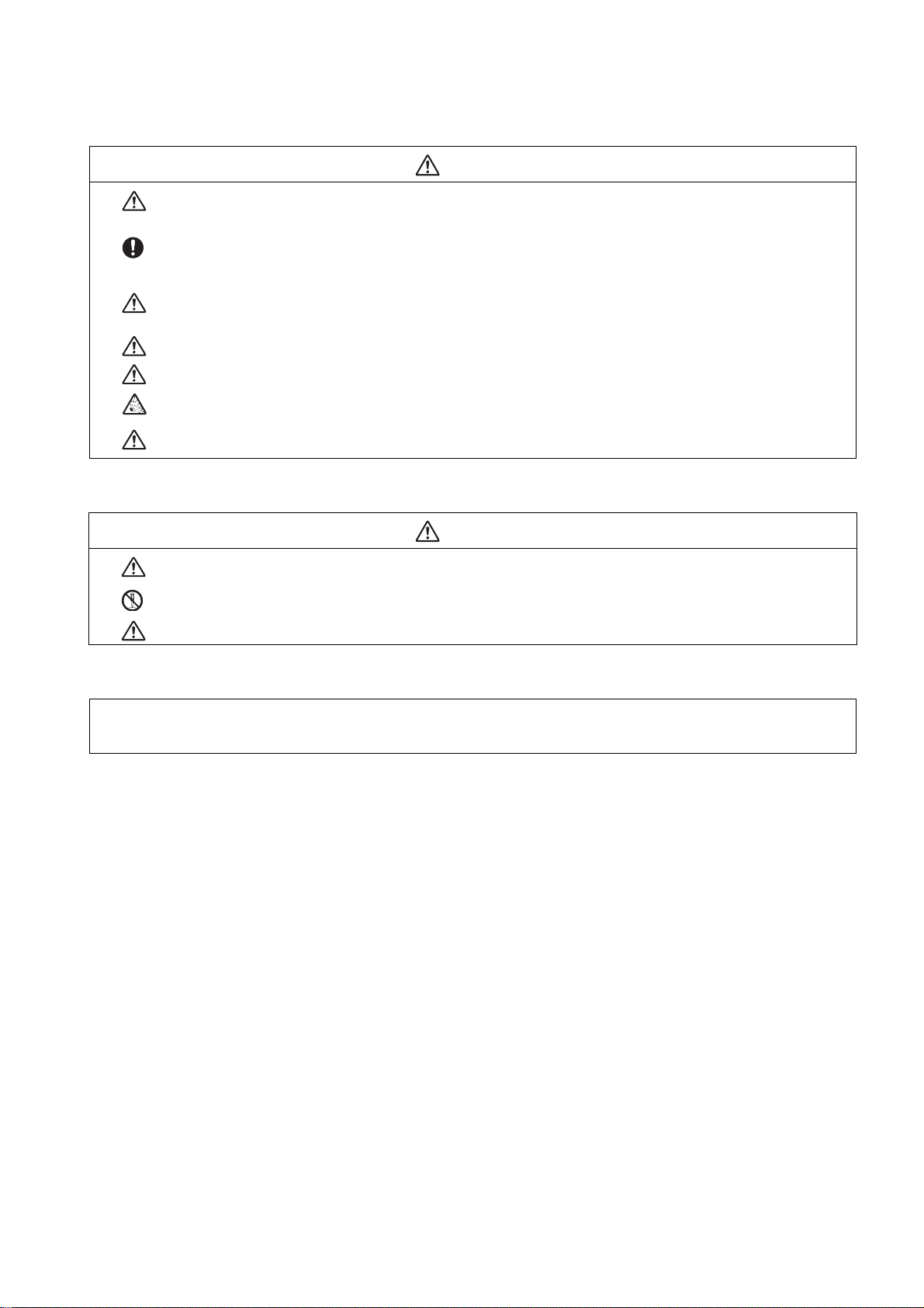
This manual classifies the safety precautions into "DANGER", "WARNING" an d "CAUTION".
DANGER
When the user could be subject to imminent fatalities or serious injuries if handling is mistaken.
WARNING
When the user could be subject to fatalities or serious injuries if handling is mistaken.
CAUTION
When the user could be subject to injuries or the property could be damaged if handling is mistaken.
Note that the items under " CAUTION" could lead to serious consequences as well depending on the situation.
All the items are important and must always be observed.
The following signs indicate prohibition and compulsory.
This sign indicates prohibited behavior (must not do).
For example, indicates "Keep fire away".
This sign indicated a thing that is pompously (must do).
For example, indicates "it must be grounded".
The meaning of each pictorial sing is as follows.
CAUTION
Prohibited
CAUTION
rotated object
Disassembly is
prohibited
CAUTION
HOT
KEEP FIRE AWAY
Danger
Electric shock risk
General instruction
Danger
explosive
Earth ground
Page 5

For Safe Use
Mitsubishi CNC is designed and manufactured solely for applications to machine tools.
Do not use this product in any applications other than those specified as above, especially those which are
substantially influential on the public interest or which are expected to have significant influence on human lives or
properties.
We will review the acceptability of the abovementioned applications, if the customer agrees not to require a specific
quality for a specific application. Please contact us for consultation.
1. Items related to prevention of electric shocks
Do not open or remove the front cover while the power is ON or during operation. The high voltage terminals and
charged sections will be exposed, and this could result in electric shocks.
Do not remove the front cover even when the power is OFF, except for the wiring works or periodic inspections.
The inside of the controller and drive unit are charged, and this could result in electric shocks.
Always wait at least 15 minutes after turning the power OFF. Then, check the voltage with a tester, etc., before
wiring works, inspections or connecting with peripheral devices. Failure to observe this could result in electric
shocks.
Earth ground the controller, drive unit and motor according to the local laws. (In Japan, ground the 200V Series
input products with Class C or higher protective grounding and the 400V Series input with Class D or higher
protective grounding.)
All wiring works, maintenance and inspections must be carried out by a qualified technician. Failure to observe this
could result in electric shocks. Contact your nearby Service Center or Service Station for replacing parts and
servicing.
Wire the controller, drive unit and motor after installation. Failure to observe this could result in electric shocks.
WARNING
Do not operate the switches with wet hands. Failure to observe this could result in electric shocks.
Do not damage, apply excessive stress, place heavy things on or sandwich the cables. Failure to observe this could
result in electric shocks.
Insulate the power lead using a fixed terminal block. Failure to observe this could result in electric shocks.
2. Items related to prevention of fire
Install the controller, drive unit, motor and regenerative resistor on non-combustible material. Installation directly on
or near combustible materials could result in fires.
If any malfunction in the unit is observed, shut off the power at the unit’s power supply side. Continuous flow of
large current could result in fires.
Install an appropriate no fuse breaker (NFB) and contactor (MC) on the power input section of the drive unit and
configure the sequence that shuts the power off upon drive unit’s emergency stop or alarm.
When a breaker is shared for multiple power supply units, the breaker may not function upon short-circuit failure in
a small capacity unit. Do not share a breaker for multiple units as this is dangerous.
Incorrect wiring and connections could cause the devices to damage or burn.
CAUTION
Page 6
3. Items related to prevention of bodily injury or property damage
DANGER
When transporting or installing a built-in IPM spindle or linear servomotor, be careful so that your hand or property
will not be trapped in the motors or other metal objects. Also keep the devices with low magnetic tolerance away
from the product.
CAUTION
Do not apply voltages to the connectors or terminals other than voltages indicated in the connection manual for the
controller or specifications manual for the drive unit. Failure to observe this could cause bursting, damage, etc.
Incorrect connections could cause the devices to rupture or damage, etc. Always connect the cables to the indicated
connectors or terminals.
Incorrect polarity (+ -) could cause the devices to rupture or damage, etc.
Persons wearing medical devices, such as pacemakers, must stay away from this unit. The electromagnetic waves
could adversely affect the medical devices.
Fins on the rear of the unit, regenerative resistor and motor, etc., will be hot during operation and for a while after
the power has been turned OFF. Do not touch or place the parts and cables, etc. close to these sections. Failure
to observe this could result in burns.
Do not enter the machine’s movable range during automatic operation. Keep your hands, feet or face away from
the spindle during rotation.
Page 7
4. General precautions
Always follow the precautions below. Incorrect handling could result in faults, injuries or electric shocks, etc.
(1) Transportation and installation
CAUTION
Correctly transport the products according to the mass.
Use motor’s suspension bolts to transport the motor itself. Do not use it to transport the motor after installation
onto the machine.
Do not stack the products exceeding the indicated limit.
Do not hold the cables, shaft or detector when transporting the motor.
Do not transport the controller or drive unit by suspending or holding the connected wires or cables.
Do not hold the front cover when transporting the unit, or the front cover could come off, causing the unit to drop.
Install on a non-combustible place where the unit’s or motor’s mass can be withstood according to the instruction
manual.
The motor does not have a complete water-proof (oil-proof) structure. Do not allow oil or water to contact or enter
the motor. Prevent the cutting chips from being accumulated on the motor as they easily soak up oil.
When installing the motor facing upwards, take measures on the machine side so that gear oil, etc., will not enter
the motor shaft.
Do not remove the detector from the motor. (The detector installation screw is treated with sealing.)
Do not allow foreign matters, especially, conductive foreign matters such as screws or metal chips, or combustible
foreign matters such as oil, to enter the controller, drive unit or motor. Failure to observe this could result in rupture
or damage.
Do not get on the product or place heavy objects on it.
Provide prescribed distance between the controller/drive unit and inner surface of the control panel/other devices.
Do not install or operate the controller, drive unit or motor that is damaged or has missing parts.
Take care not to cut hands, etc. with the heat radiating fins or metal edges.
Do not block the intake/outtake ports of the motor with the cooling fan.
Install the controller’s display section and operation board section on the spot where cutting oil will not reach.
The controller, drive unit and motor are precision devices, so do not drop or apply thumping vibration and strong
impacts on them.
Hard disk unit is a precision device, so do not drop or apply strong impacts on it.
Store and use the units according to the environment conditions indicated in each specifications manual.
Securely fix the motor to the machine. The motor could come off during operation if insecurely fixed.
Page 8
CAUTION
Always install the motor with reduction gear in the designated direction. Failure to observe this could result in oil
leaks.
Always install a cover, etc., over the shaft so that the rotary section of the motor cannot be touched during motor
rotation.
When installing a coupling to the servomotor shaft end, do not apply impacts by hammering, etc. The detector could
be damaged.
Use a flexible coupling when connecting with a ball screw, etc., and keep the shaft core deviation smaller than the
tolerable radial load of the shaft.
Do not use a rigid coupling as an excessive bending load will be applied on the shaft and could cause the shaft to
break.
Do not apply a load exceeding the tolerable level onto the motor shaft. The shaft or bearing could be damaged.
Before using this product after a long period of storage, please contact the Mitsubishi Service Station or Service
Center.
Following the UN recommendations, battery units and batteries should be transported based on the international
regulations such as those determined by International Civil Aviation Organization (ICAO), International Air
Transport Association (IATA), International Maritime Organization (IMO) and U.S. Department of Transportation
(DOT).
Page 9
(2) Items related to wiring
RA
RA
COM COM
Control
output
signal
Drive unit
Control
output
signal
Drive unit
(24VDC) (24VDC)
RS-232C
NC unit
Device
Switch
AC socket
CAUTION
Correctly wire this product. Failure to observe this could result in motor runaway, etc.
Do not install a phase advancing capacitor, surge absorber or radio noise filter on the output side of the drive unit.
Correctly connect the output side (terminal U, V, W). The motor will not run properly if incorrectly connected.
Always install an AC reactor per each power supply unit.
Always install an appropriate breaker per each power supply unit. A breaker cannot be shared for multiple power
supply units.
Do not directly connect a commercial power supply to the motor. Failure to observe this could result in faults.
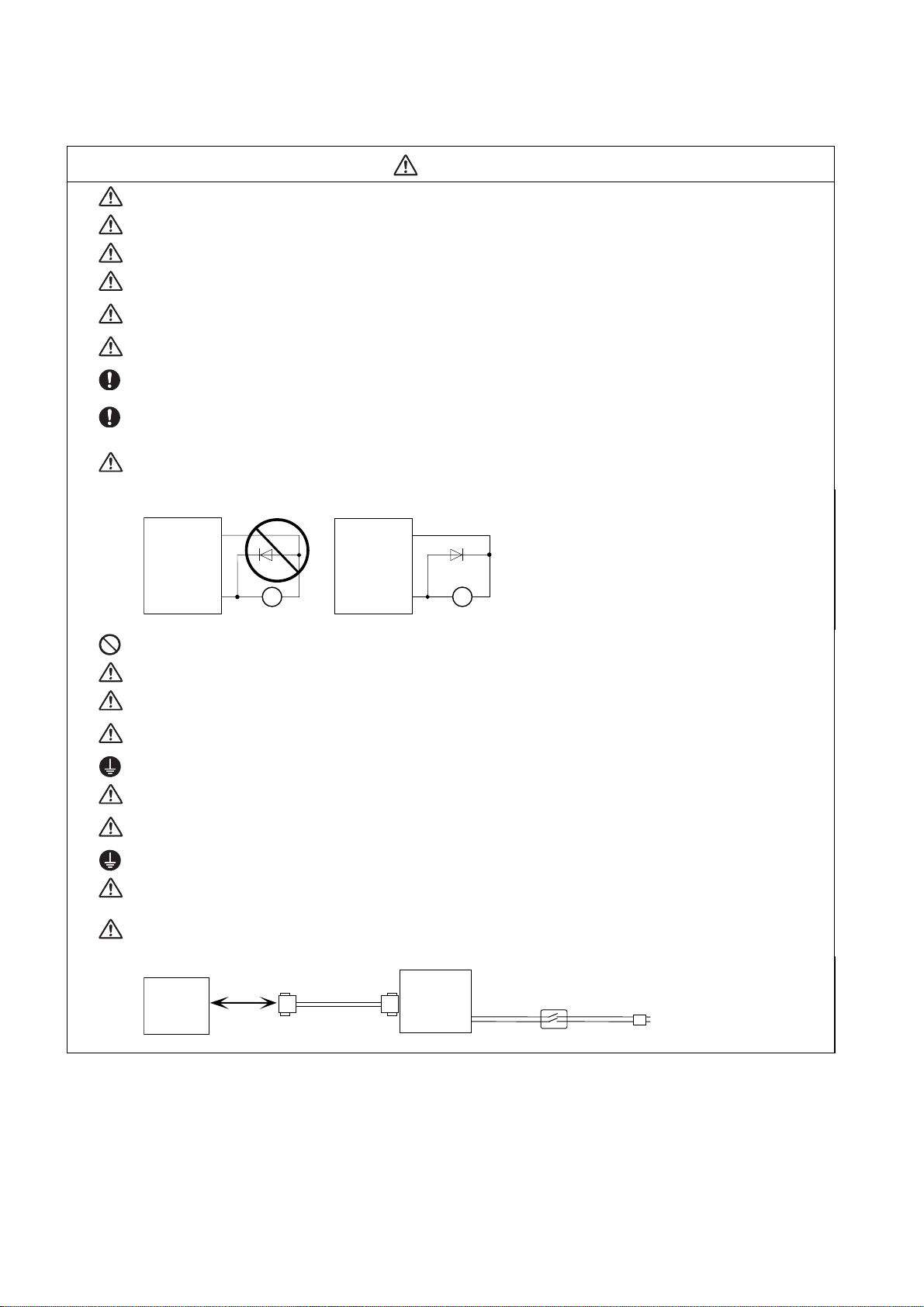
When using an inductive load such as relays, always connect a diode in parallel to the load as a noise
countermeasure.
When using a capacitive load such as a lamp, always connect a protective resistor serially to the load to suppress
rush currents.
Do not mistake the direction of the surge absorption diode to be installed on the DC relay for the control output
signal. If mistaken, the signal will not be output due to fault in the drive unit, and consequently the protective circuit,
such as emergency stop, could be disabled.
Do not connect or disconnect the cables between units while the power is ON.
Do not connect or disconnect the PCBs while the power is ON.
Do not pull the cables when connecting/disconnecting them.
Securely tighten the cable connector fixing screw or fixing mechanism. The motor could come off during operation
if insecurely fixed.
Always treat the shield cables indicated in the Connection Manual with grounding measures such as cable clamps.
Separate the signal wire from the drive line or power line when wiring.
Use wires and cables whose wire diameter, heat resistance level and bending capacity are compatible with the
system.
Ground the device according to the requirements of the country where the device is to be used.
Wire the heat radiating fins and wires so that they do not contact.
When using the RS-232C device as a peripheral device, caution must be paid for connector connection/
disconnection. Always use a double-OFF type AC power supply switch on the device side, and connect/disconnect
the connector with the AC power supply on the device side OFF.
Page 10
(3) Adjustments
CAUTION
Check and adjust programs and each parameter before starting operation. Failure to observe this could result in
unpredictable operations depending on the machine.
Do not make drastic adjustments or changes as the operation could become unstable.
(4) Usage
CAUTION
Install an external emergency stop circuit so that the operation can be stopped and the power turns OFF
immediately when unforeseen situation occurs. A contactor, etc., is required in addition to the shutoff function
mounted in the controller.
Turn OFF the power immediately if any smoke, abnormal noise or odor is generated from the controller, drive unit
or motor.
Only a qualified technician may disassemble or repair this product.
Do not alter.
Use a noise filter, etc. to reduce the effect of electromagnetic disturbances in the case where electromagnetic
disturbances could adversely affect the electronic devices used near the drive unit.
Use the drive unit, motor and each regenerative resistor with the designated combination. Failure to observe this
could result in fires or faults.
The combination of the motor and drive unit that can be used is determined. Be sure to check the models of motor
and drive unit before test operation.
The brakes (electromagnetic brakes) mounted in the servomotor are used for the purpose of holding, and must not
be used for normal braking. Also, do not run the motor with the motor brake applied. Motor brake is used for the
purpose of holding.
For the system running via a timing belt, install a brake on the machine side so that safety can be ensured.
Be sure to confirm SERVO OFF (or READY OFF) when applying the electromagnetic brake. Also, be sure to
confirm SERVO ON prior to releasing the brake.
When using the DC OFF type electromagnetic brake, be sure to install a surge absorber on the brake terminal.
Do not connect or disconnect the cannon plug while the electromagnetic brake’s power is ON. The cannon plug
pins could be damaged by sparks.
After changing programs/parameters, or after maintenance/inspection, always carry out a test operation before
starting actual operation.
Use the power that are complied with the power specification conditions (input voltage, input frequency, tolerable
instantaneous power failure time) indicated in each specifications manual.
When making detector cables, do not mistake connection. Failure to observe this could result in malfunction,
runaway or fire.
Page 11
(5) Troubleshooting
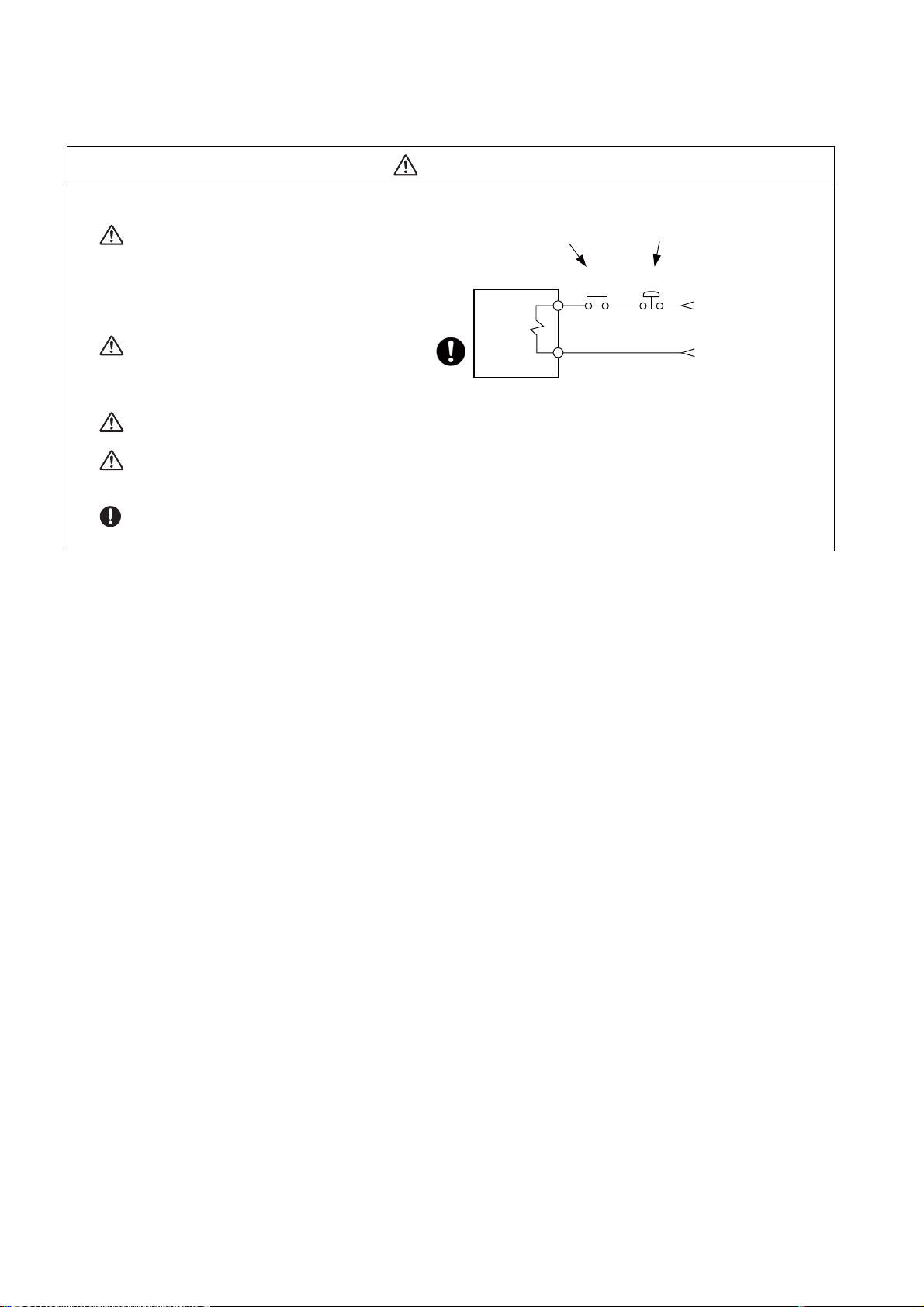
Use a motor with electromagnetic brakes or
establish an external brake mechanism for the
purpose of holding; this serves as
countermeasures for possible hazardous
situation caused by power failure or p rod uct
fault.
CAUTION
Shut off with motor
brake control output
Motor
Shut off with CNC brake
control PLC output
MBR EMG
Use a double circuit structure for the
electromagnetic brake’s operation circuit so
that the brakes will activate even when the
external emergency stop signal is issued.
The machine could suddenly restart when the power is restored after an instantaneous power failure, so stay away
from the machine. (Design the machine so that the operator safety can be ensured even if the machine restarts.)
To secure the absolute position, do not shut off the servo drive unit’s control power supply when its battery voltage
drops (warning 9F) in the servo drive unit side.
If the battery voltage drop warning alarm occurs in the controller side, make sure to back up the machining
programs, tool data and parameters, etc. with the input/output device before replacing the battery. Depending on
the level of voltage drop, memory loss could have happened. In that case, reload all the data backed up before the
alarm occurrence.
Electromagnetic
brake
24VDC
Page 12
(6) Maintenance, inspection and part replacement
CAUTION
Periodically back up the programs, tool data and parameters to avoid potential data loss. Also, back up those data
before maintenance and inspections.
When replacing the battery on the controller side, the machining programs, tool data and parameters should be
backed up with the input/output device beforehand. In case the memory is damaged in replacing the batteries,
reload all the data backed up before replacing the battery.
The electrolytic capacitor’s capacity will drop due to deterioration. To prevent secondary damage due to
capacitor’s faults, Mitsubishi recommends the electrolytic capacitor to be replaced approx. every five years even
when used in a normal environment. Contact the Service Center or Service Station for replacements.
Do not perform a megger test (insulation resistance measurement) during inspection.
Do not replace parts or devices while the power is ON.
Do not short-circuit, charge, overheat, incinerate or disassemble the battery.
There may be a unit filled with substitute Freon in the heat radiating fins of the 37kW or smaller unit. Be careful not
to break the heat radiating fins during maintenance or replacement.
(7) Disposal
CAUTION
Take the batteries and backlights for LCD, etc., off from the controller, drive unit and motor, and dispose of them
as general industrial wastes.
Do not alter or disassemble controller, drive unit, or motor.
Collect and dispose of the spent batteries and the backlights for LCD according to the local laws.
(8) General precautions
To explain the details, drawings given in the instruction manual, etc., may show the unit with the cover or safety partition
removed. When operating the product, always place the cover or partitions back to their original position, and operate as
indicated in the instruction manual, etc.
Page 13

Page 14

Treatment of waste
The following two laws will apply when disposing of this product. Considerations must be made to each law.
The following laws are in effect in Japan. Thus, when using this product overseas, the local laws will have a
priority. If necessary, indicate or notify these laws to the final user of the product.
(1) Requirements for "Law for Promotion of Effective Utilization of Resources"
(a) Recycle as much of this product as possible when finished with use.
(b) When recycling, often parts are sorted into steel scraps and electric parts, etc., and sold to scrap
contractors. Mitsubishi recommends sorting the product and selling the members to appropriate
contractors.
(2) Requirements for "Law for Treatment of Waste and Cleaning"
(a) Mitsubishi recommends recycling and selling the pr oduct when n o longer needed a ccording to item
(1) above. The user should make an effort to reduce waste in this manner.
(b) When disposing a product that cannot be resold, it shall be treated as a waste product.
(c) The treatment of industrial waste must be commissioned to a licensed industrial waste treatment
contractor, and appropriate measures, including a manifest control, must be taken.
(d) Batteries correspond to "primary batteries", and must be disposed of according to local disposal
laws.
Page 15

Page 16

Disposal
(Note) This symbol mark is for EU countries only.
This symbol mark is according to the directive 2006/66/EC Article 20 Information for endusers and Annex II.
Your MITSUBISHI ELECTRIC product is designed and manufactured with high quality materials and
components which can be recycled and/or reused.
This symbol means that batteries and accumulators, at their end-of-life, should be disposed of
separately from your household waste.
If a chemical symbol is printed beneath the symbol shown above, this chemical symbol means that the
battery or accumulator contains a heavy metal at a certain concentration. This will be indicated as
follows:
Hg: mercury (0,0005%), Cd: cadmium (0,002%), Pb: lead (0,004%)
In the European Union there are separate collection systems for used batteries and accumulators.
Please, dispose of batteries and accumulators correctly at your local community waste collection/
recycling centre.
Please, help us to conserve the environment we live in!
Page 17

Page 18

Trademarks
MELDAS, MELSEC, EZSocket, EZMotion, iQ Platform, MELSOFT, GOT, CC-Link, CC-Link/LT and CC-Link
IE are either trademarks or registered trademarks of Mitsubishi Electric Co rporation in Japan and/or other
countries.
Ethernet is a registered trademark of Xerox Corporation in the United States and/or other countries.
Microsoft® and Windows® are either trademarks or registered trademarks of Microsoft Corporation in the
United States and/or other countries.
CompactFlash and CF are either trademarks or registered trademarks of SanDisk Corporation in the United
States and/or other countries.
UNIX is a registered trademark of The Open Group in the United States and/or other countries.
Intel® and Pentium® are either trademarks or registered trademarks of Intel Corporation in the United States
and/or other countries.
Other company and product names that appear in this manual are trademarks or registe red trademarks of t he
respective companies.
Page 19

Page 20

本製品の取扱いについて
( 日本語 /Japanese)
本製品は工業用 ( クラス A) 電磁環境適合機器です。販売者あるいは使用者はこの点に注意し、住商業環境以外で
の使用をお願いいたします。
Handling of our product
(English)
This is a class A product. In a domestic environment this product may cause radio interference in which case the
user may be required to take adequate measures.
본 제품의 취급에 대해서
( 한국어 /Korean)
이 기기는 업무용 (A 급 ) 전자파적합기기로서 판매자 또는 사용자는 이 점을 주의하시기 바라며 가정외의 지역에
서 사용하는 것을 목적으로 합니다 .
Page 21

Page 22

Contents
1 System Configuration... ... .... ... ... ....................................... ... ... ....................................... ... ........................... 1
1.1 System Basic Configuration Drawing..................................................................................................... 2
1.2 General Connection Diagram .................................................. ... ... ....................................... ................. 3
1.3 List of Configuration....................................... ....................................... ... .............................................. 5
1.3.1 List of Units.................................................................................................................................... 5
1.3.2 Durable Parts................................................................................................................................. 6
1.3.3 Replacements................................................................................................................................ 6
1.3.4 List of Cables................................................................................................................................. 7
2 General Specifications ..................................................................... ... .... .................................................... 9
2.1 Environment Conditions................. ....................................... ... ....................................... ..................... 10
2.2 Control Unit.................................... ... ... .... ... ... ... ... ....................................... ... .... .................................. 11
2.3 Display Unit............................. .... ... ....................................... ... ... ......................................................... 21
2.4 Keyboard Unit...... ... ... .... ... ... ... .... ...................................... .... ... ............................................................ 22
2.5 Operation Panel I/O Unit...................... .... ... ....................................... ... ... ............................................ 24
2.6 Remote I/O Unit...... ... .... ... ... ... .... ...................................... .... ...................................... ......................... 36
2.7 External Power Supply Unit ................................................................................................................. 43
2.8 Manual Pulse Generator...................................................................................................................... 45
2.9 Synchronous Feed Encoder ................................................................................................................ 47
2.10 MITSUBISHI CNC Machine Operation Panel.................................................................................... 48
2.10.1 MITSUBISHI CNC Machine Operation Panel A......................................................................... 48
2.10.2 MITSUBISHI CNC Machine Operation Panel B......................................................................... 55
2.11 Exclusive CF Cards for MITSUBISHI CNC........................................................................................ 59
2.11.1 Precautions for Use of Commercially Available CF Cards......................................................... 59
3 Installation.................. ....................................... ... ....................................... ... ... ......................................... 61
3.1 Heat Radiation Countermeasures........................................................................................................ 62
3.2 Noise Countermeasures...... ... .... ... ... ... .... ... ... ...................................................................................... 65
3.2.1 Connection of FG (Frame Ground).............. .... ... ... ... ....... ... ... .... ... ... ... ... .... ... ... ... .... ... ... ... ....... ..... 65
3.2.2 Shield Clamping of Cables........................................................................................................... 66
3.2.3 Connecting Spark Killers.............................................................................................................. 66
3.3 Unit Installation ................. ... ... .... ...................................... .... ... ............................................................ 67
3.3.1 Display Unit.................................................................................................................................. 67
3.3.2 Keyboard Unit.............................................................................................................................. 68
3.3.3 Operation Panel I/O Unit.............................................................................................................. 68
3.3.4 Control Unit Battery...................................................................................................................... 69
4 Connection ................................. ... .... ... ....................................... ... ... ......................................................... 71
4.1 Precautions for Wiring............. .... ... ... ... ....................................... ... .... .................................................. 72
4.1.1 Precautions when Connecting/Disconnecting Cables ............... ... ... ... ... .... ... ... ... .... ... ... ... ... .... ... .. 72
4.1.2 Precautions for Using Optical Communication Cable.................................................................. 75
4.1.2.1 Optical Communication Cable Outline and Parts ................................................................ 75
4.1.2.2 Precautions for Handling Optical Communication Cable..................................................... 75
4.1.2.3 Precautions for Laying Optical Communication Cable .................. .... ... ... ... .... ... .................. 76
4.1.3 Precautions for Connecting 24V Power Supply........................................................................... 76
4.2 Connection of Control Unit.......................... ... ... ....................................... ... ... ...................................... 77
4.2.1 Control Unit Connection System Drawing....................................................................................77
4.2.2 Connecting with Power Supply................................. .... ... ... ... .... ... ...... ... .... ... ... ... .... ... ... ... ... .. ....... 78
4.2.3 Connecting with Emergency Stop Signal.....................................................................................79
4.2.4 Connecting with Operation Panel I/O Unit................................................................................... 81
4.2.5 Connecting with Drive Unit........................................................................................................... 82
4.2.5.1 Connecting with MDS-DM2 Series...................................................................................... 83
4.2.5.2 Connecting with MDS-DJ Series ......................................................................................... 84
4.2.6 Connecting with RS-232C Device....................................... ... .... ... ...... ... .... ... ... ... .... ... ... ... ... ....
Connecting with Skip Signal (Sensor)........................................ ... ... ... ... .... ... ...... .... ... ... ... ... ......... 87
4.2.7
4.2.8 Connecting with Synchronous Feed Encoder/ Manual Pulse Generator..................................... 89
4.2.8.1 Handle Numbers.................................................................................................................. 89
4.2.9 Connecting with Safety Observing I/O Device............................................................................. 90
..... 85
Page 23

4.3 Connection of Operation Panel I/O Unit . ... .... ... ... ... ....... ... ... ... .... ... ... ... .... ... ... ... ... .... ... ... ... ....... ............. 91
4.3.1 Operation Panel I/O Unit Connection System Drawing ............................................................... 91
4.3.2 Connecting with Keyboard Unit.................................................................................................... 92
4.3.3 Connecting with Manual Pulse Generator (MPG)........................................................................ 93
4.3.3.1 Handle Numbers.................................................................................................................. 94
4.3.4 Connecting with Machine Operation Panel........................... ... ... .... ... ... ... ... .... ... ... ... .... ... ... ...... .... 94
4.3.4.1 Wiring for 24V Common Input.............................................................................................. 95
4.3.4.2 Wiring for 0V Common Input................................................................................................95
4.3.4.3 Wiring for Source Type Output (FCU7-DX621/DX711/DX721/DX731) ............................... 96
4.3.4.4 Outline of Analog Signal Output Circuit ............................................................................... 97
4.4 Connection of Remote I/O Unit.............. ... .... ... ... ... ... .... ...................................... .... ... .......................... 98
4.4.1 Connection and Station No. Setting on Remote I/O Unit............................................................. 98
4.4.2 Station No. Setting when Using Multiple Remote I/O Units ....................................................... 100
4.4.3 Connecting FCUA-DX101/141 Unit with Machine Control Signal.............................................. 104
4.4.4 Connecting FCUA-DX141 Unit with Analog Input/Output Signal............................................... 106
4.4.5 Connecting FCUA-DX111 Unit with Machine Control Signal..................................................... 107
4.4.6 Connecting FCUA-DX121 Unit with Machine Control Signal..................................................... 109
4.5 Connection of MITSUBISHI CNC Machine Operation Panel............................................................. 111
Appendix 1 Cable............................... ... .... ... ....................................... ... ..................................................... 115
Appendix 1.1 Cable Wire and Assembly......... .... ... ... ...... .... ... ... ... .... ... ... ... .... ... ... ... ... .... ... ... ....... ... ... ........ 117
Appendix 1.2 CNP2E-1 Cable.................................................................................................................. 119
Appendix 1.3 CNP3EZ-2P/CNP3EZ-3P Cable................... ... ... ... .... ... ... ....... ... ... ... ... .... ... ... ... .... ... ... ... ... .. 120
Appendix 1.4 CNV22J-K1P / CNV22J-K2P Cable.... ... ... .... ... ... ... .... ... ... ... .... ... ... ... ....... ... ... ... .... ... ... ... ... .. 121
Appendix 1.5 CNV2E-8P/CNV2E-9P Cable............................................................................................. 122
Appendix 1.6 CNV2E-HP Cable............................................................................................................... 123
Appendix 1.7 CNV2E-K1P / CNV2E-K2P Cable...................................................................................... 124
Appendix 1.8 DG21 Cable ..................................... ... ... ....................................... ... ... ............................... 125
Appendix 1.9 DG22 Cable ..................................... ... ... ....................................... ... ... ............................... 126
Appendix 1.10 DG23 Cable ..................................................................................................................... 127
Appendix 1.11 DG24 Cable ..................................................................................................................... 128
Appendix 1.12 DG25 Cable ..................................................................................................................... 129
Appendix 1.13 F023/F024 Cable ............................................................................................................. 130
Appendix 1.14 F034/F035 Cable ............................................................................................................. 131
Appendix 1.15 F070 Cable....................................................................................................................... 132
Appendix 1.16 F110 Cable....................................................................................................................... 133
Appendix 1.17 F120 Cable....................................................................................................................... 134
Appendix 1.18 F170 Cable....................................................................................................................... 135
Appendix 1.19 F221 Cable....................................................................................................................... 136
Appendix 1.20 F320/F321 Cable ............................................................................................................. 137
Appendix 1.21 F351 Cable....................................................................................................................... 138
Appendix 1.22 FCUA-R030 Cable......................................................................................................... .. 139
Appendix 1.23 FCUA-R031 Cable......................................................................................................... .. 140
Appendix 1.24 FCUA-R050/R054 Cable.................................................................................................. 141
Appendix 1.25 FCUA-R211 Cable......................................................................................................... .. 142
Appendix 1.26 FCUA-R300/FCUA-R301 Cable....................................................................................... 143
Appendix 1.27 G011 Cable...................................................................................................................... 145
Appendix 1.28 G023/G024 Cable............................................................................................................ 146
Appendix 1.29 G071 Cable...................................................................................................................... 147
Appendix 1.30 G300 Cable.......................................................................................................
Appendix 1.31 G
Appendix 1.32 G380 Cable...................................................................................................................... 150
Appendix 1.33 G395 Cable...................................................................................................................... 151
Appendix 1.34 G396 Cable...................................................................................................................... 152
Appendix 1.35 G460 Cable...................................................................................................................... 153
Appendix 1.36 MR-BKS1CBL-A1-H / MR-BKS1CBL-A2-H Cable........................................................... 154
Appendix 1.37 MR-PWS1CBL-A1-H / MR-PWS1CBL-A2-H Cable......................................................... 155
Appendix 1.38 R-TM Terminator Connector............................................................................................156
Appendix 1.39 SH21 Cable...................................................................................................................... 157
Appendix 1.40 SH41 Cable...................................................................................................................... 158
Appendix 1.41 List of Cable Connector Sets ........................................................................................... 159
301 Cable...................................................................................................................... 149
............... 148
Page 24

Appendix 2 EMC Installation Guidelines .................................................................................................. 161
Appendix 2.1 Introduction .......................................... .... ... ... ....................................... ... ... ....................... 162
Appendix 2.2 EMC Directives .................................................................................................................. 162
Appendix 2.3 EMC Measures .................................................................................. ... ... .......................... 163
Appendix 2.4 Panel Structure ........................................... ... ... .... ...................................... .... ... ................ 163
Appendix 2.4.1 Measures for Control Panel Body.............................................................................. 163
Appendix 2.4.2 Measures for Door..................................................................................................... 164
Appendix 2.4.3 Measures for Power Supply....................................................................................... 164
Appendix 2.5 Measures for Wiring in Panel............................................................................................. 165
Appendix 2.5.1 Precautions for Wiring in Panel..................................................................................165
Appendix 2.5.2 Shield Treatment of Cables .......................................................................................166
Appendix 2.6 EMC Countermeasure Parts.............................................................................................. 168
Appendix 2.6.1 Shield Clamp Fitting................................................................................................... 168
Appendix 2.6.2 Ferrite Core................................................................................................................ 169
Appendix 2.6.3 Surge Absorber.......................................................................................................... 170
Appendix 2.6.4 Selection of Stabilized Power Supply ........................................................................ 172
Appendix 3 Restrictions for Lithium Batteries......................................................................................... 173
Appendix 3.1 Restriction for Packing....................................................................................................... 174
Appendix 3.1.1 Target Products ......................................................................................................... 175
Appendix 3.1.2 Handling by User ....................................................................................................... 176
Appendix 3.1.3 Reference .................................................................................................................. 177
Appendix 3.2 Products information data sheet (ER battery).................................................................... 178
Appendix 3.3 Issuing Domestic Law of the United States for Primary Lithium Battery Transportation.... 180
Appendix 3.3.1 Outline of Regulation ................................................................................................. 180
Appendix 3.3.2 Target Products ......................................................................................................... 180
Appendix 3.3.3 Handling by User ....................................................................................................... 180
Appendix 3.3.4 Reference .................................................................................................................. 180
Appendix 3.4 Restriction related to EU Battery Directive......................................................................... 181
Appendix 3.4.1 Important Notes ......................................................................................................... 181
Appendix 3.4.2 Information for end-user............................................................................................. 181
Appendix 4 Precautions for Compliance to UL/c-UL Standards............................................................ 183
Page 25

Page 26

1
1
System Configuration
Page 27
1 System Configuration
MITSUBISHI CNC
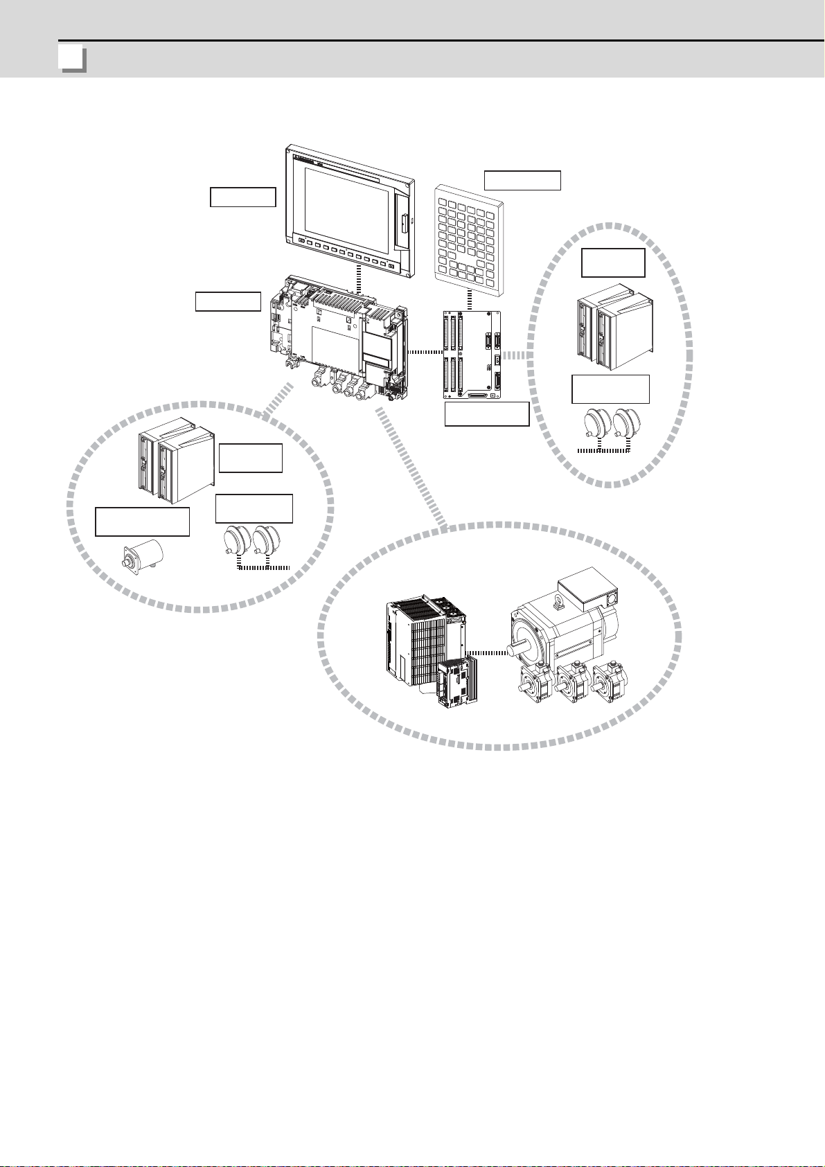
1.1 System Basic Configuration Drawing
Display unit
Keyboard unit
Operation panel
I/O unit
Control unit
Manual pulse
generator
Servo/Spindle drive units
Motors
Synchronous feed
encoder
Remote I/O
unit
Manual pulse
generator
Remote I/O
unit
(Note 1) Control unit is mounted on the back side of the display unit.
(Note 2) Operation panel I/O unit is mounted on the back side of the keyboard unit.
(Note 3) For the drive unit configuration, refer to the Instruction Manual of the drive unit you use.
2
Page 28

E70 Series Connection Manual
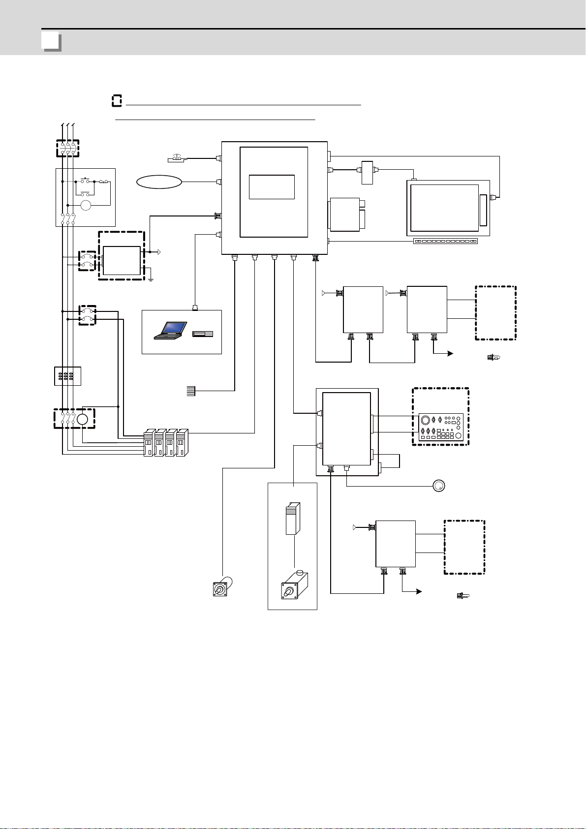
1.2 General Connection Diagram
L1 L2 L3
FCU7-KB0xx
FG
RIO2
EMG
SIO
NCKB
LCD
LED driver : HN281
1ch:F034
Sensor signals
Max.8points
LAN
CG3x
EMG
(VGA:640×480)
RIO1
OPT
FRONT
FCU7-DX621/7x1
DCIN
FCUA-DX1x1
RIO1
SKIP ENC
USER 2ch
2ch
1ch
INV
F120
12V:F320/F321
5V:F023/F024
FCUA-R030
G395/G396/G380
FCUA-R050/054
FCU7-DU120-13
G011
RIO2RIO1
DCIN
FCUA-DX1x1
CG71
DC24V DC24V
MENUKEY
2ch:F035
1ch
FCUA-R211
/SH41
CG71
HN441
max.0.5m
G300/G301
<G402>
RIO3 MPG
DI-L/R
RIO2RIO1
DCIN
FCUA-DX1x1
DC24V
FCUA-R211
/SH41
FCUA-R211
/SH41
F351
DI-L/R
FCUAR300
/R301
FCUAR300
/R301
F070
F070
F070
<G487>
D-AL
MC
ON OFF
MC
MC
MC
DCOUT
FG
ACIN
DC24V
DCIN
F070
CP/NFB
CP/NFB
HN793
CF card I/F
<G497>
FCU7-MU558
<G488>
OSE1024
USB
2ch
ENC
5V:G023/G024
The name with brackets < > indicates the cable for the unit.
Dotted lines indicate the sections prepared by the machine tool builder.
No-fuse breaker (NFB)
24VDC stabilized
power supply
Circuit protector (CP)
AC reactor
RS232C device
Contactor
Skip signal input
Drive units
Manual pulse
generator
Synchronous feed encoder
CNC control unit
Main card HN768
Memory card
Front
memory
I/F card
Display unit
Menu keys
Remote I/O unit Remote I/O unit
Machine
control relay/
contact
To the next remote I/O
or terminator
Machine operation
panel made by
machine tool builder
Keyboard unit
Operation panel I/O unit
Manual pulse generator
Remote I/O unit
To the next remote I/O
or terminator
Machine
control relay/
contact
Ethernet device
Select
1.2 General Connection Diagram
(Note 1) For information on how to connect the drive unit, refer to the drive unit's manual.
(Note 2) For a connection of the MITSUBISHI CNC Machine Operation Panel, refer to "Connection: Connection of
MITSUBISHI CNC Machine Operation Panel" to be described.
3
Page 29
1 System Configuration
MITSUBISHI CNC
L1 L2 L3
MC
ON OFF
MC
MC
EMG
F120
G300/G301
F070
FG
DCOUT
FG
ACIN
DC24V
CP/NFB
CP/NFB
D-AL
MC
FCU7-KB0xx
RIO2
EMG
SIO
NCKB
LCD
LED driver : HN281
1ch:F034
Sensorsignals
Max.8points
LAN
CG3x
(VGA:640×480)
RIO1
OPT
FRONT
FCU7-DX621/721
DCIN
FCUA-DX1x1
RIO1SKIP ENC
USER 2ch
2ch
1ch
INV
12V:F320/F321
5V:F023/F024
FCUA-R030
G395/G396/G380
FCUA-R050/054
FCU7-DU120-13
G011
RIO2RIO1
DCIN
FCUA-DX1x1
CG71
DC24V DC24V
MENUKEY
2ch:F035
1ch
FCUA-R211
/SH41
CG71
HN441
max.0.5m
<G402>
RIO3 MPG
DI-L/R
RIO2RIO1
DCIN
FCUA-DX1x1
DC24V
FCUA-R211
/SH41
FCUA-R211
/SH41
F351
DI-L/R
FCUAR300
/R301
FCUAR300
/R301
F070
F070
F070
<G487>
DCIN
HN793
CF card I/F
<G497>
FCU7-MU558
<G488>
AO
F221
max.30m
OSE1024
max.30m
USB
Remote I/O unit
To the next remote I/O
or terminator
Machine
control relay/
contact
Manual pulse generator
Machine operation
panel made by
machine tool builder
Keyboard unit
Operation panel I/O unit
Skip signal input
Drive units
AC reactor
Contactor
24VDC stabilized
power supply
Circuit protector (CP)
The name with brackets < > indicates the cable for the unit.
No-fuse breaker (NFB)
Dotted lines indicate the sections prepared by the machine tool builder.
CNC control unit
Main card HN768
Memory card
Front
memory
I/F card
Display unit
Menu keys
To the next remote I/O
or terminator
Machine
control relay/
contact
Spindle motor
Synchronous feed encoder
RS232C device
Ethernet device
[Analog Spindle Configuration]
(Note 1) For information on how to connect the drive unit, refer to the drive unit's manual.
(Note 2) For a connection of the MITSUBISHI CNC Machine Operation Panel, refer to "Connection: Connection of
MITSUBISHI CNC Machine Operation Panel" to be described.
4
Page 30
E70 Series Connection Manual
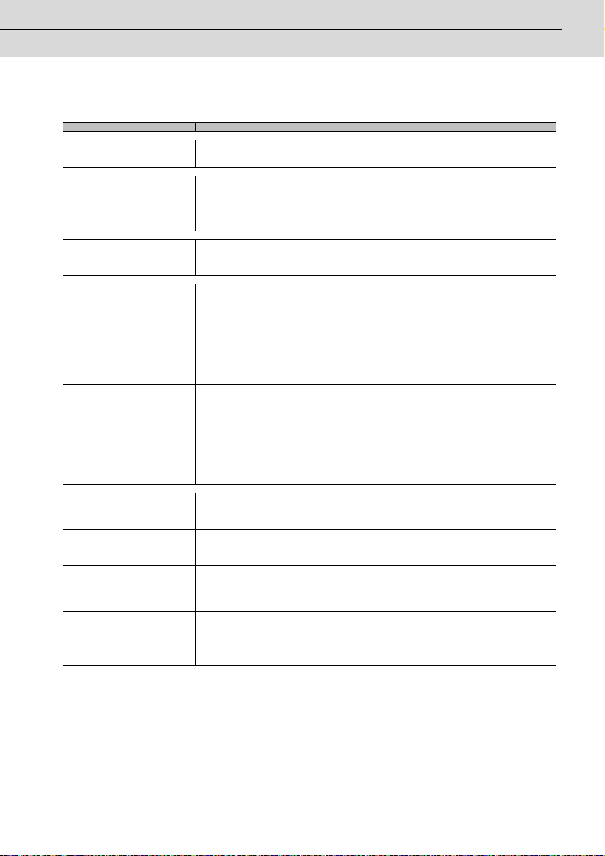
1.3 List of Configuration
1.3 List of Configuration
1.3.1 List of Units
[Control unit]
Classification Type Components Remarks
NC functions
and display controller
[Display unit]
8.4-type color TFT
(VGA:640*480)
[Keyboard unit]
Keyboard for 8.4-type display unit
Sheet keys
Keyboard for 8.4-type display unit
Lathe system sheet keys
[Operation panel I/O unit]
DI 24V/0V common input
DO Source output
AO Analog output
DI 24V/0V common input
DO Source output
DI 24V/0V common input
DO Source output
AO Analog output
DI 24V/0V common input
DO Source output
[Remote I/O unit]
DI 24V/0V common input
DO Source output
DI 24V/0V common input
DO Source output
DI 24V/0V common input
DO Source output
AO Analog output
DI 24V/0V common input
DO Source output
AI Analog input
AO Analog output
FCU7-MU558
FCU7-DU120-13
FCU7-KB024
FCU7-KB025
FCU7-DX621
FCU7-DX711
FCU7-DX721
FCU7-DX731
FCUA-DX101 RX312
FCUA-DX111 RX312+RX322-1
FCUA-DX121 RX312+RX322
FCUA-DX141 RX312+RX341
Main control card
Memory card
Front side memory I/F card
LCD panel
Backlight driver
Menu keys
Driver cable
LED backlight cable
LCD cable
Escutcheon, key switch
G402 cable
Escutcheon, key switch
G402 cable
Base card
Terminator (R-TM)
Add-on card
Base card
Terminator (R-TM)
Base card
Terminator (R-TM)
Add-on card
Base card
Terminator (R-TM)
Add-on card
Export Tarde Control Order and Foreign
Exchange Order noncompliant unit
Front side memory I/F is normally equipped
with the control unit
ONG layout (for M system/L system, XYZ)
ONG layout (for L system, XZF)
DI: 64-points 24V/0V common type
DO: 48-points source type
MPG:2ch
AO: 1 point
Occupied stations (fixed): 1, 2, 3, 7, 8
RIO3 extensible stations: 4, 5, 6
DI: 64-points 24V/0V common type
DO: 64-points source type
MPG:2ch
Occupied stations (fixed): 1, 2, 7, 8
RIO3 extensible stations: 3, 4, 5, 6
DI: 96-points 24V/0V common type
DO: 80-points source type
MPG:2ch
AO: 1 point
Occupied stations (fixed): 1, 2, 3, 7, 8
RIO3 extensible stations: 4, 5, 6
DI: 96-points 24V/0V common type
DO: 96-points source type
MPG:2ch
Occupied stations (fixed): 1, 2, 3, 7, 8
RIO3 extensible stations: 4, 5, 6
DI: 32-points 24V/0V common type
(photo coupler insulation)
DO: 32-points source type (non-insulation)
Number of occupied stations: 1
DI: 64-points 24V/0V common type
(photo coupler insulation)
DO: 48-points source type (non-insulation)
Number of occupied stations: 2
DI: 64-points 24V/0V common type
(photo coupler insulation)
DO: 48-points source type (non-insulation)
AO: 1 point
Number of occupied stations: 2
DI: 32-points 24V/0V common type
(photo coupler insulation)
DO: 32-points source type (non-insulation)
AI: 4 points
AO: 1 point
Number of occupied stations: 2
5
Page 31

1 System Configuration
MITSUBISHI CNC
[External power supply unit]
External power supply with power supply
ON/OFF function
[Manual pulse generator]
5V Manual pulse generator UFO-01-2Z9
12V Manual pulse generator HD60C HD60C
[Encoder]
Synchronous feed encoder OSE1024-3-15-68 OSE1024-3-15-68
[MITSUBISHI CNC machine operation panel]
MITSUBISHI CNC machine operation
panel A
MITSUBISHI CNC machine operation
panel B
[Cable connector sets]
For ENC,SKIP,SIO,MPG,AO FCUA-CS000
For RIO FCUA-CS301
For PD25/PD27 ACIN FCUA-CN200
For PD25/PD27 DCOUT
For PD25/PD27 ON/OFF
For EMG F120
For RIO FCUA-CN211
For DCIN,F070 FCUA-CN220
For DIO FCUA-CN300 Connector (7940-6500SC,2pcs.)
[Original manufactured memory card]
Exclusive CF cards for MITSUBISHI CNC
256MB
Exclusive CF cards for MITSUBISHI CNC
2GB
Classification Type Components Remarks
PD25
FCU7-KB921
FCU7-KB926 Escutcheon, Switch
3-178127-6
1-175218-5
1-178288-5
1-175218-5
005057-9403
0016020103
FCU7-CF256M FCU7-CF256M 256MB capacity
FCU7-CF002G FCU7-CF002G 2GB capacity
Power supply card
Case set
UFO-01-2Z9
(Produced by NIDEC NEMICON)
Escutcheon, key switch
control card
Connector (10120-3000VE,2pcs),
Shell kit (10320-52F0-008,2pcs)
Connector (7940-6500SC,4pcs.),
Strain relief (3448-7940,2pcs.)
Connector (2-178128-3),
Contact (1-175218-5,3pcs.)
Connector (3-178127-6),
Contact (1-175218-5,6pcs.)
Connector (1-178288-5),
Contact (1-175218-5,6pcs.)
Connector (005057-9403),
Contact (0016020103,3pcs.)
Connector (1-178288-3),
Contact (1-175218-2,3pcs.)
Connector (2-178288-3),
Contact (1-175218-5,3pcs)
Input 200VAC
Output 24VDC (3A)
Input 5VDC
100pulse/rev
Input 12VDC
25pulse/rev
Input 5VDC
1024pulse/rev
Mitsubishi standard 55 key
(Note 1) Operation panel I/O unit can be mounted on the back side of the keyboard unit.
(Note 2) Operation panel I/O units for 700 Series (FCU7-DX67x/ FCU7-DX77x) are not available.
(Note 3) DI: Digital input signals, DO: Digital output signals, AI: Analog input signals, AO: Analog output signals
1.3.2 Durable Parts
Control unit battery Q6BAT
Backlight for FCU7-DU120-13(*) 84LHS16
Key sheet for FCU7-KB024 N330B532G51
Key sheet for FCU7-KB025 N330B532G52
(*) Contact the Service Center, Service Station, Sales Office or delayer for repairs or part replacement.
Durable parts Part type
1.3.3 Replacements
Protection fuse LM40
Replacements Part type
6
Page 32

E70 Series Connection Manual
1.3 List of Configuration
1.3.4 List of Cables
Type Application
CNP2E-1-xM Motor side PLG cable 2, 3, 4, 5, 7, 10, 15, 20, 25, 30 30m
CNP3EZ-2P-xM Spindle side detector cable 2, 3, 4, 5, 7, 10, 15, 20, 25, 30 30m
CNP3EZ-3P-xM Spindle side detector cable 2, 3, 4, 5, 7, 10, 15, 20, 25, 30 30m
CNV22J-K1P-0.3M Detector extension cable for HF-KP motor 0.3 0.3m
CNV22J-K2P-0.3M Detector extension cable for HF-KP motor 0.3 0.3m
CNV2E-8P-xM
CNV2E-9P-xM
CNV2E-HP-xM MDS-B-HR unit cable 2, 3, 4, 5, 7, 10, 15, 20, 25, 30 30m
CNV2E-K1P-xM Detector cable for HF-KP motor (load side angle) 2, 3, 5, 7, 10 10m
CNV2E-K2P-xM Detector cable for HF-KP motor (reverse load side angle) 2, 3, 5, 7, 10 10m
DG21-xM
DG22-xM
DG23-xM
DG24-xM
DG25-xM
F023 LxM
F024 LxM
F034 LxM RS-232C I/F cable: 1ch 0.5, 1, 2, 3, 5, 8, 10 15m (*)
F035 LxM RS-232C I/F cable: 2ch 0.5, 1, 2, 3, 5, 8, 10 15m (*)
F070 LxM 24VDC power cable 0.5, 1.5, 3, 5, 8, 10, 15, 20 30m
F110 LxM 24VDC power cable for PD25 0.5, 1.5, 3, 5, 8, 10, 15 15m
F120 LxM Emergency stop cable 0.5, 1.5, 3, 5, 8, 10, 15, 20 30m
F170 LxM ON/OFF switch cable for PD25 0.5, 1.5, 3, 5, 8, 10, 15 15m
F221 LxM Analog output cable 1, 2, 3, 5, 8, 10, 15, 20 30m
F320 LxM
F321 LxM
F351
FCUA-R030-xM SKIP input 3, 7 20m
FCUA-R031-xM Analog input/output 2, 3, 7 30m
FCUA-R050-xM Encoder input (straight, with connector) 5 30m
FCUA-R054-xM Encoder input (right angle, with connector) 3, 5, 10, 15, 20 30m
FCUA-R211-xM Remote I/O (with terminal block) 0.3, 1, 2, 3, 5, 8, 10, 15, 20 30m (*)
FCUA-R300
FCUA-R301-xM
G011 LxM Operation panel I/O interface cable 0.5 0.5m
G023 LxM
G024 LxM
G071 xM DC24V relay cable for MITSUBISHI CNC machine operation panel 0.5 0.5m
G300 LxM
G301 LxM
G380 LxM
G395 LxM
G396 LxM
G460 xM
Motor side detector cable (for A74(N)/A51/A48)/
Ball screw side detector cable
Motor side detector cable (for A74(N)/A51/A48)/
Ball screw side detector cable
Battery cable
(For drive unit - battery unit)
Battery cable
(For servo drive unit - servo drive unit)
* This cable is required to supply the power from the battery unit to mult iple
drive units.
Battery cable
(For servo drive unit -battery box)
5V spply/DO output cable
(For servo drive unit -battery box)
Battery cable
(For servo drive unit -battery box)
Manual pulse generator cable (5V): 1ch
(for connection to operation panel I/O unit)
Manual pulse generator cable (5V): 2ch
(for connection to operation panel I/O unit)
Manual pulse generator cable (12V): 1ch
(for connection to operation panel I/O unit)
Manual pulse generator cable (12V): 2ch
(for connection to operation panel I/O unit)
DI/DO cable (one side connector)
(for operation panel I/O unit)
DI/DO cable (one side connector)
(for remote I/O unit)
DI/DO cable (both side connectors)
(for remote I/O unit)
Manual pulse generator cable (5V): 1ch
(for connection to control unit)
Manual pulse generator cable (5V): 2ch
(for connection to control unit)
LAN cross cable
(Shielded cable is recommended when the length will be 1m or more)
LAN straight cable
(Shielded cable is recommended when the length will be 1m or more)
Optical communication cable (PCF type with reinforced sheath)
(for wiring outside of the panel)
Optical communication cable
(for wiring outside of the panel)
Optical communication cable (POF type without reinforced sheath)
(for wiring inside of the panel)
Cable between MITSUBISHI CNC machine operation panel A and
MITSUBISHI CNC machine operation panel B
(POF type with reinforced sheath)
Length (m) of cables provided
by Mitsubishi
2, 3, 4, 5, 7, 10, 15, 20, 25, 30 30m
2, 3, 4, 5, 7, 10, 15, 20, 25, 30 30m
0.3, 0.5, 1, 5 5m
0.3, 0.5, 1, 2, 3, 5, 7, 10 10m
0.3, 0.5, 1, 2, 3, 5, 7, 10 10m
0.3, 0.5, 1, 2, 3, 5, 7, 10 10m
0.3, 0.5, 1, 2, 3, 5, 7, 10 10m
1, 2, 3, 5, 8, 10, 15, 20 20m
1, 2, 3, 5, 8, 10, 15, 20 20m
1, 2, 3, 5, 8, 10, 15, 20 50m
1, 2, 3, 5, 8, 10, 15, 20 50m
3 50m
3 50m
1, 2, 3, 5 50m
1, 2, 3, 5, 8, 10, 15, 20 20m (*)
1, 2, 3, 5, 8, 10, 15, 20 20m (*)
1, 3, 5, 10 10m
11m
5, 10, 12, 15, 20, 25, 30 30m
3, 5, 7, 10 10m
0.3, 0.5, 1, 2, 3, 5 10m
0.5 0.5m
Max. cable
length
7
Page 33

1 System Configuration
MITSUBISHI CNC
Type Application
MR-BKS1CBLxMA1-H
MR-BKS1CBLxMA2-H
MR-PWS1CBLxMA1-H
MR-PWS1CBLxMA2-H
R-TM
SH21 xM Power supply communication cable 0.35, 0.5, 1, 2, 3, 5, 10, 15, 20, 30 30m
SH41 xM
Brake cable for HF-KP motor (load side angle) 2, 3, 5, 7, 10 10m
Brake cable for HF-KP motor (reverse load side angle) 2, 3, 5, 7, 10 10m
Power cable for HF-KP motor (load side angle) 2, 3, 5, 7, 10 10m
Power cable for HF-KP motor (reverse load side angle) 2, 3, 5, 7, 10 10m
Remote I/O
Interface terminator
Remote I/O
(between units in a panel)
Length (m) of cables provided
by Mitsubishi
--
0.3, 0.5, 0.7 1m (*)
Max. cable
(Note 1) Asterisks "x" in type columns indicate cable length (unit: m).
(Note 2) Lengths indicated with an asterisk (*) in the max. cable length column indicate the maximum cable length
when connecting via other unit.
length
8
Page 34

9
2
General Specifications
Page 35

2 General Specifications
MITSUBISHI CNC
2.1 Environment Conditions
Item
Ambient
temperature
Gener
Ambient
al
humidity
specifi
cation
Vibration
s
resistance
Shock
resistance
Working
atmosphere
Requir
Power voltage
ed
power
Power capacity
specifi
cation
Instantaneous stop
s
tolerance time
Heating
value
Mass (kg)
Others
Outline
dimension
Unit name Control unit Display unit Keyboard unit
Type FCU7-MU558 FCU7-DU120-13 FCU7-KB024/025
During
operation
During
storage
Long
term
Short
term
(max.)
(mm)
10 to 75% RH (with no dew condensation)
10 to 95% RH (with no dew condensation) (Note 1)
4.9m/s2 or less (during operation)
29.4m/s2 or less (during operation)
No corrosive gases, dust or oil mist
24VDC ±5%
Ripple noise 200mV
(P-P)
24V 2.5A - -
12.0W 3.3W 1.0W
1.0 1.5 0.8 0.4
235(width) x
173(height) x
73(depth)
(Depth from the plate
mounting surface: 60)
3.3V/12VDC 5VDC 3.3V/5VDC
20ms - 20ms(min)(Note 7)
260(width) x
200(height)
0 to 55C°
-20 to 60C°
(Provided by the control unit)
140(width) x 200(height)
Operation panel
I/O unit
FCU7-DX621/711/
721/731
-
(Note 2)
Control section: 5.0W
(Note 3)
120(width) x
180(height)
Machine operation
panel
FCU7-KB921/926
24VDC ±5%(Note 7)
0.25A(Note 7)
6W
FCU7-KB921:1.2
FCU7-KB926:0.5
FCU7-KB921:
260(W) x 140(H)
FCU7-KB926:
140(W) x 140(H)
Item
General
specifications
Required power
specifications
Others
Unit name Remote I/O unit
Type FCUA-DX101 FCUA-DX111 FCUA-DX121 FCUA-DX141
During
Ambient temperature
Ambient humidity
Vibration resistance
Shock resistance
Working atmosphere
Input power voltage
Power capacity
operation
During
storage
Long term
Short term 10 to 95% RH (with no dew condensation) (Note 1)
24V 0.7A (Note 4) 24V 1.5A (Note 4) 24V 0.7A (Note 4)
10 to 75% RH (with no dew condensation)
4.9m/s2 or less (during operation)
29.4m/s2 or less (during operation)
No corrosive gases or dust
24VDC±5% Ripple noise 200mV (P-P)
Instantaneous stop
tolerance time
Heating value (max.)
Mass (kg)
25W (Note 5) 30W (Note 5) 30W (Note 5)
0.5 0.6 0.6 0.6
0 to 55C°
-20 to 60C°
-
(Note 1) "Short term" means within one month.
(Note 2) For the current value of the I/O circuit, calculate with the number of points used and load.
(Note 3) For the heating value of the I/O circuit, calculate with the number of points used.
(Note 4) Allows only the amount to be consume d by control circuit.
(Note 5) Differs according to the number of machine input operation points and the load and number of points
connected to the machine output. The maximum value applies when all points are ON.
(Note 6) These units, which are open equipments, must be installed within a sealed metal control panel.
(Note 7) FCU7-KB926 does not need 24VDC power supply input.
10
Page 36

E70 Series Connection Manual
2.2 Control Unit
2.2 Control Unit
(7)
(8) (9)
(10) (12) (13) (14) (15) (16) (17)
(2) (5) (6)
(3)
(4)
(11) (18)
(1)
6
208
214
235
6
156
168
173
21
52
100
Dimension and names of parts
[FCU7-MU558]
Connector
name
No.
(1) USB Front USB memory I/F (11) RIO1 Remote I/O unit I/F
(2) CF Front CF card I/F (12) MENUKEY Menu key I/F
(3) INV Display unit backlight driver I/F (13) ENC
(4) DC IN 24VDC input (14) SKIP Skip input 8ch
(5) EMG External emergency stop input (15) SIO
(6) ADONCCB Expansion card slot (16) BAT Battery (Q6BAT) I/F
(7) LCD Display unit signal I/F (17) FG FG terminal
(8) OPT Optical communication I/F (18) LED
(9) LAN Ethernet I/F
(10) CG71 Operation panel I/O unit I/F
(1) Front USB memory I/F (USB)
Do not connect devices other than USB memories.
When using a commercially available USB memory, performance check must be made by machine tool builder.
Function No.
Connector
name
Function
Encoder input 1ch
(5V manual pulse generator
input 2ch)
Serial communication (RS232C) I/F 2ch
11
Page 37

2 General Specifications
MITSUBISHI CNC
(2) Front CF card I/F (CF)
13
It is recommended to use CF cards of the original equipment manufactured parts.
Mitsubishi is unable to guarantee the machine operation when a commercially available CF card or SD memory
card (SD-CF adapter is required) is used. In that case, performance check must be made carefully by machine tool
builder.
(Refer to "General Specifications: Exclusive CF cards for MITSUBISHI CNC: Precautions for Use of Commercially
Available CF Cards".)
(3) Display unit backlight driver I/F (INV)
(4) 24VDC input (DCIN)
1 I+24V
2 0V
3 FG
<Cable side connector type>
Connector: 2-178288-3
Contact: 1-175218-5 x3
Recommended manufacturer: Tyco Electronics
(a) Specifications of power supply
Consider the following characteristics when selecting the stabilized power supply (prepared by machine
tool builder). Use a power supply that complies with CE Marking or that follows the safety standards given
below.
[Stabilized power supply selection items]
Item Standard setting
Output Voltage fluctuation ±5% or less of 24VDC
Ripple noise 200mV (P-P)
Power capacity 2.5A or more
Output holding time 20ms
Overcurrent protection Required
[Standards]
Safety Standards: UL1950, CSA C22.2 No.234 approved, IEC950 compliant
Noise Terminal Voltage: FCC Class A, VCCI-Class A
High Harmonics Current Restrictions: IEC61000-3-2
(Note) 2 4VDC voltage may drop instantaneously due to rush current at the beginning of 24V power
supply to the control unit. The level of voltage drop depends on the capacity of the power
supply. Do not share the power supply with the devices that have alarms to warn the voltage
drop.
CAUTION
1. Using a stabilized power supply without overcurrent protection may cause the unit's failure due to miswiring of
24V.
12
Page 38

E70 Series Connection Manual
2.2 Control Unit
(5) External emergency stop input (EMG)
31
1 FG
2 I EMG IN
3 O +24V
* Be sure to connect EMG terminal cable (G123) to the connector when not used.
<Cable side connector type>
Connector: 005057-9403
Contact: 0016020103
Recommended manufacturer: MOLEX
(6) Expansion card slot (ADONCCB)
(7) Display unit signal I/F (LCD)
(8) Optical communication I/F (OPT)
<Cable side connector type>
(PCF type)
Connector: CF-2D101-S
Recommended manufacturer: Japan Aviation Electronics
(POF type)
Connector: PF-2D101
Recommended manufacturer: Japan Aviation Electronics
13
Page 39

2 General Specifications
MITSUBISHI CNC
(9) Ethernet I/F (LAN)
81
13 1
26 14
1 OTD+
2 OTD-
3 I RD+
4
5
6 I RD-
7
8
* Connect connector case with FG pattern.
* Use cross cable (G300) when directly connecting a device such as a personal computer to the unit.
<Cable side connector type>
Connector: 5-569550-3
Recommended manufacturer: Tyco Electronics
(10) Operation panel I/O unit I/F (CG71)
1
2
3
4
5
6
7
8
9
10
11
12
13
GND 14 GND
5V 15 5V
5V 16 3.3V
GND 17 GND
O KBCS0* 18 O KBCS1*
O KBCS2* 19 O KBAD0
O KBAD1 20 O KBAD2
IKBD0 21 I KBD1
IKBD2 22 I KBD3
O KBRES* 23 O RDYOUT*
OBUZOUT* 24 3.3V
I/O TXRX3 25 I/O TXRX3*
O SCAN36 26 O SCAN37
* Connect connector case with FG pattern.
<Cable side connector type>
Plug: 10126-3000VE
Shell: 10326-52F0-008
Recommended manufacturer: 3M
14
Page 40

E70 Series Connection Manual
2.2 Control Unit
(11) Remote I/O unit I/F (RIO1)
13
10 1
20 11
Up to eight remote I/O stations can be connected.
1 I/O TXRX1
2 I/O TXRX1*
3 0V
<Cable side connector type>
Connector: 1-178288-3
Contact: 1-175218-2 x3
Recommended manufacturer: Tyco Electronics
(12) Menu key I/F (MENUKEY)
(13) Encoder input 1ch/ 5V manual pulse generator input 2ch (ENC)
Synchronous feed encoder or 5V manual pulse generator can be connected to this connector.
1 0V 11 0V
2 I ENC1Z 12 IENC1Z*
3 I ENC1B 13 IENC1B*
4 I ENC1A 14 IENC1A*
5 0V 15 0V
6 O5V 16 O5V
7 IHA2A 17 IHA2B
8 IHA1A 18 IHA1B
9 NC 19 NC
10 O5V 20 O5V
* Connect connector case with FG pattern.
<Cable side connector type>
Plug: 10120-3000VE
Shell: 10320-52F0-008
Recommended manufacturer: 3M
15
Page 41

2 General Specifications
MITSUBISHI CNC
(a) Input for synchronous feed encoder
A
A*
B
B*
Z
Z*
abcde
T
phase
phase
phase
phase
phase
phase
T
b da c e
A(B) phase
B(A) phase
<Specification of input part>
Number of pulse phases
Signal output of the encoder Line driver output
Signal
voltage
Power supply voltage 5VDC±10%
Current consumption 200mA or less
Number of pulses per rotation 1024 pulse/rev
Input frequency (rotation speed) 136kHz or less (8000r/min or less)
Cable length 50m or less
Input voltage range 0V to 5.25V
Differential-input voltage VIT+ 0.2V to 5.25V
Differential-input voltage VIT- -5.25V to -0.2V
Three phases (A phase, B phase, a phase difference 90 degrees,
Z phase) (Refer to the waveform below.)
a.b.c.d.e: A phase or B phase rising edge (falling edge) phase difference = T/4 ± T/10
(b) Input for 5V manual pulse generator
<Specification of input part>
Number of pulse phases
Signal output of manual pulse generator Voltage output, open collector output
Signal voltage
Power supply voltage 5VDC±10%
Current consumption 100mA or less
Number of pulses per rotation 25 pulse/rev, 100 pulse/rev
Input frequency (rotation speed)
Cable length 20m or less
Two phases (A phase, B phase, a phase difference 90 degrees)
(Refer to the waveform below.)
H level 3.5V to 5.25V
L level 0V to 0.5V
1kHz or less
(40r/s or less for 25pluse/rev, 10r/s or less for 100pluse/rev)
a.b.c.d.e: A phase or B phase rising edge (falling edge) phase difference = T/4 ± T/10
T: A or B phase cycle
16
Page 42

E70 Series Connection Manual
2.2 Control Unit
(c) 5V manual pulse generator input/output circuit
10 1
20 11
+5V
Connector
pin No.
8
HA1A
7
HA2A
Signal
input
18
HA1B
17
HA2B
10
+5V
20
+5V
Power
output
1
0V
11
0V
When using the synchronous feed encoder and the manual pulse generator at the same time, connect
the manual pulse generator to the operation panel I/O unit or use a distribution cable made by the
machine tool builder.
(14) Skip input 8ch (SKIP)
+5V
0V
0V
Control
circuit
0V
1 COM 11 COM
2 I SKIP0 12 I SKIP1
3 I SKIP2 13 I SKIP3
4 NC 14 NC
5 COM 15 COM
6 NC 16 NC
7 I SKIP4 17 I SKIP5
8 I SKIP6 18 I SKIP7
9 NC 19 NC
10 NC 20 NC
* Connect connector case with FG pattern.
<Cable side connector type>
Plug: 10120-3000VE
Shell: 10320-52F0-008
Recommended manufacturer: 3M
17
Page 43

2 General Specifications
MITSUBISHI CNC
(a) Skip signal input conditions
Ton
0V
+24V
External signal
Connection to 24V common
0V(RG)
0V(RG)
0V(RG)
24VDC
(Machine side)
Control
circuit
Control
circuit
(Machine side)
Connection to 24V common
Connection to 0V common
24VDC
Input
voltage
Input
voltage
Input
voltage
Input
voltage
Use the input signal within the following condition ranges.
24V common 0V common
1 Input voltage at external contact ON 6V or less 18V or more, 25.2V or less
2 Input current at external contact ON 6mA or more
3 Input voltage at external contact OFF 20V or more, 25.2V or less 4V or less
4 Input current at external contact OFF 2mA or less
5 Input resistance Approx. 2.2kΩ
6 Input signal holding time (Ton) 2ms or more
7 Internal response time 0.08ms or less
8 Machine side contact capacity +30V or more, 16mA or more
Connection to 0V common
Ton
+24V
External signal
0V
18
Page 44
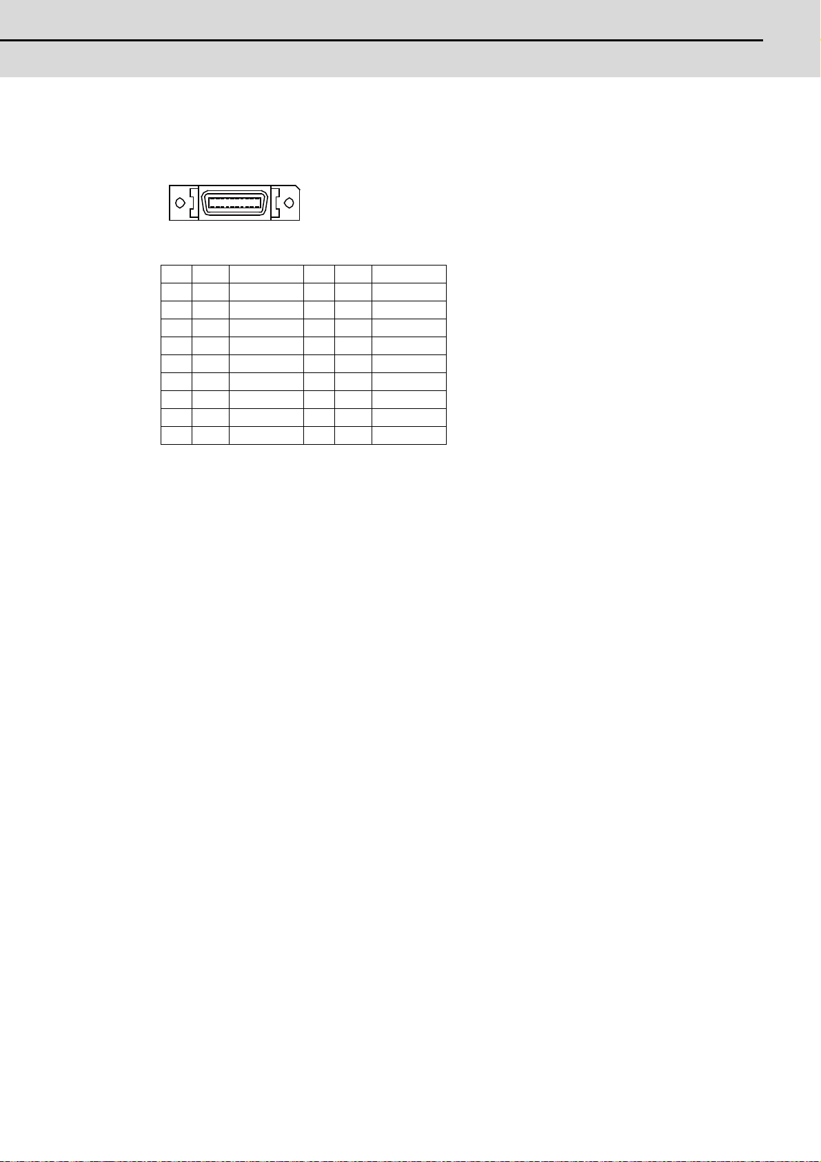
E70 Series Connection Manual
2.2 Control Unit
(15) Serial communication (RS-232C) I/F 2ch (SIO)
10 1
20 11
1 0V 11 0V
2 I RD1(RXD1) 12 OSD1(TXD1)
3 ICS1(CTS1) 13 ORS1(RTS1)
4 O DR1(DSR1) 14 IER1(DTR1)
5 0V 15 0V
6 NC 16 NC
7 I RD2(RXD2) 17 OSD2(TXD2)
8 ICS2(CTS2) 18 ORS2(RTS2)
9 O DR2(DSR2) 19 IER2(DTR2)
10 NC 20 NC
* Connect connector case with FG pattern.
<Cable side connector type>
Plug: 10120-3000VE
Shell: 10320-52F0-008
Recommended manufacturer: 3M
(16) Battery (Q6BAT) I/F (BAT)
(17) FG terminal (FG)
19
Page 45

2 General Specifications
MITSUBISHI CNC
(18) LED
Name
Name Function At fault Conditions
24VDCIN 24VDC input check Not lit
DCOUT Internal output voltage check Not lit
LCDON
PSEMG
WDER System error display Lit (Red)
BATALM Battery voltage drop Lit (Red) Battery voltage has dropped to 2.7V or less
12VDC output voltage check
for backlight driver
External emergency stop
status display
Not lit
Lit (Red) External emergency stop signal has inputted
(1) Failure of 24VDC input
(2) Fuse is disconnected near DCIN connector
(1) Failure of internal voltage output in control unit
(2) Short circuit of 5VDC output on CG71 or ENC
(1) Failure of 12VDC output in control unit
(2) 24VDC input voltage is +20V or less
(1) Failure of control unit
(2) SRAM data is broken
20
Page 46

E70 Series Connection Manual
2.3 Display Unit
2.3 Display Unit
260
200
20 110(Space required for wiring)
260 ( )
250 ± 0.3
4- M3
200 ( )
190 ± 0.3
244
184
Unit outline
Unit outline
Screw
(Square hole)
Outline dimension
[FCU7-DU120-13 (8.4-type)]
(Note 1) The above side view shows the state with the control unit mounted.
(Note 2) Consider the minimum radius value of optical communication cable for the bottom space. (Refer to
"Connection : Precautions for Using Optical Communication Cable".)
<Panel cut dimension drawing>
21
Page 47

2 General Specifications
MITSUBISHI CNC
2.4 Keyboard Unit
140
200
20
110
(
Space required for wiring
)
Outline dimension
[FCU7-KB024 (8.4-type)]
(Note) The above side view shows the state with the operation panel I/O unit FCU7-DX721 mounted.
<Panel cut dimension drawing>
140
(Unit outline)
0
0.3
190 0.3
(Unit outline)
200
(Square hole)
122
4-M3
Screw
182
22
Page 48

E70 Series Connection Manual
2.4 Keyboard Unit
[FCU7-KB025 (8.4-type)]
140
200
20 110
(Space required for wiring)
140
0
122
182
200
0.3
4-M3
190 0.3
Screw
(Unit outline)
(Unit outline)
(Square hole)
(Note) The above side view shows the state with the operation panel I/O unit FCU7-DX721 mounted.
<Panel cut dimension drawing>
23
Page 49
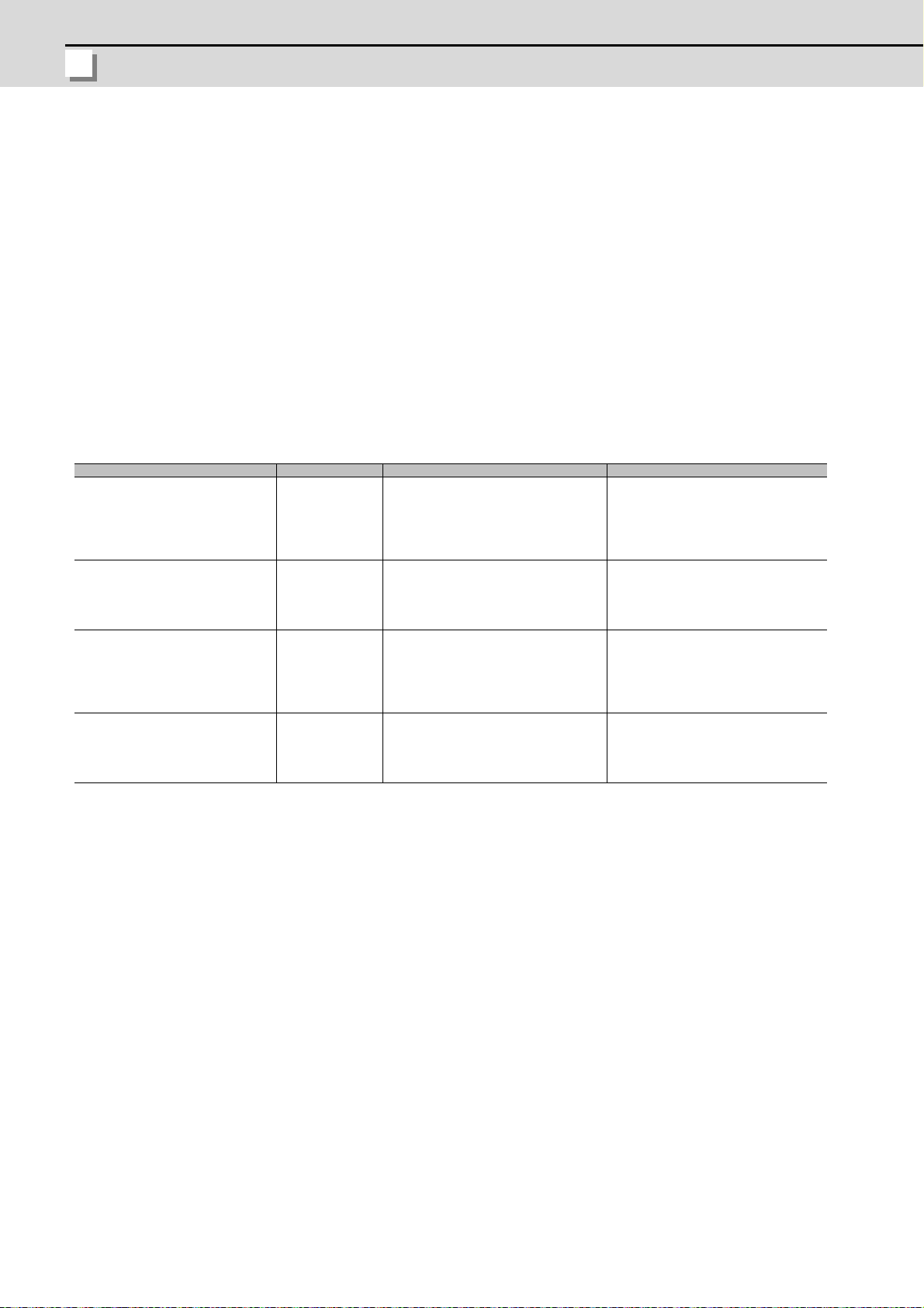
2 General Specifications
MITSUBISHI CNC
2.5 Operation Panel I/O Unit
Characteristics of operation panel I/O unit are as follows.
(1) Number of DI/DO points that can be mounted on the machine operation panel is 64/64 at the minimum and 96/96 at
the maximum.
Operation panel I/O unit DI/DO uses equivalent serial link connections as those used for remote I/O.
(2) Remote I/O interface --- 1ch
Extension with remote I/O unit is possible up to 4 stations.
(a) When FCU7-DX711 is used: Up to 4 stations, 128 points/128 points in total, are available.
(b) When any one of FCU7-DX621/721/731 is used: Up to 3 stations, 96 points/96 points in total, are available.
(Note) The maximum number of stations that can be extended is described above whether DI/DO of the
operation panel I/O unit is used or not.
(3) Manual pulse generator --- 2ch
5V and 12V manual pulse generators can be connected.
(4) Installation on the back side of the keyboard unit is possible. Allows space saving inside the operation panel.
Classification Type Components Remarks
DI 24V/0V common input
DO Source output
AO Analog output
DI 24V/0V common input
DO Source output
DI 24V/0V common input
DO Source output
AO Analog output
DI 24V/0V common input
DO Source output
FCU7-DX621
FCU7-DX711
FCU7-DX721
FCU7-DX731
Base card
Terminator (R-TM)
Add-on card
Base card
Terminator (R-TM)
Base card
Terminator (R-TM)
Add-on card
Base card
Terminator (R-TM)
Add-on card
DI: 64-points 24V/0V common type
DO: 48-points source type
MPG:2ch
AO: 1 point
Occupied stations (fixed): 1, 2, 3, 7, 8
RIO3 extensible stations: 4, 5, 6
DI: 64-points 24V/0V common type
DO: 64-points source type
MPG:2ch
Occupied stations (fixed): 1, 2, 7, 8
RIO3 extensible stations: 3, 4, 5, 6
DI: 96-points 24V/0V common type
DO: 80-points source type
MPG:2ch
AO: 1 point
Occupied stations (fixed): 1, 2, 3, 7, 8
RIO3 extensible stations: 4, 5, 6
DI: 96-points 24V/0V common type
DO: 96-points source type
MPG:2ch
Occupied stations (fixed): 1, 2, 3, 7, 8
RIO3 extensible stations: 4, 5, 6
(Note 1) The station Nos. occupied by the operation panel I/O unit cannot be changed.
(Note 2) Set the number of DI points that are simultaneously turned ON to be less than half of the total points. If many
points are set to be simultaneously turned ON in high temperature, operation panel I/O unit may be
deteriorated due to the heat.
24
Page 50

E70 Series Connection Manual
2.5 Operation Panel I/O Unit
Dimension and names of parts
(4)
(1)
(10)
(7)
(8)
(11)
(12)
110 (
116
179
(13)
Space required for wiring)
116 ( )
106 ± 0.3
4-M3
179 ( )
171 ± 0.3
Unit outline
Screw
Unit outline
Fixing screw (4 pcs.) M3x25
(with plain washer and spring washer)
NCKB Connector
[FCU7-DX621]
<Dimension drawing for installing on the panel> <Installation on the back side of the keyboard>
Operation panel I/O unit can be installed on the back side
of the keyboard.
(Note) Use M3x2 5 screws (with spring washer and plain washer) when mounting the operation panel I/O unit.
25
Page 51

2 General Specifications
MITSUBISHI CNC
[FCU7-DX711]
(4)
(5)
(1)
(10)
(2)
(7)
(8)
(11)
(12)
110 (
116
179
(13)
Space required for wiring)
116 ( )
106 ± 0.3
4-M3
179 ( )
171 ± 0.3
Unit outline
Screw
Unit outline
NCKB
Connector
Fixing screw (4 pcs.)
M3x25
(with plain washer and spring washer)
<Dimension drawing for installing on the panel> <Installation on the back side of the keyboard>
Operation panel I/O unit can be installed on the back side
of the keyboard.
(Note) Use M3x25 screws (with spring washer and plain washer) when mounting the operation panel I/O unit.
26
Page 52

E70 Series Connection Manual
2.5 Operation Panel I/O Unit
[FCU7-DX721/ FCU7-DX731]
(4)
(5)
(1)
(10)
110 (
(2)
(7)
(8)
(11)
(12)
(3)
(6)
(9)
116
179
(13)
Space required for wiring)
116 ( )
106 ± 0.3
4-M3
179 ( )
171 ± 0.3
Unit outline
Screw
Unit outline
NCKB
Connector
Fixing screw (4 pcs.)
M3x25
(with plain washer and spring washer)
(Note) (9) is not available for FCU7-DX731.
<Dimension drawing for installing on the panel> <Installation on the back side of the keyboard>
Operation panel I/O unit can be installed on the back side
of the keyboard.
(Note) Use M3x2 5 screws (with spring washer and plain washer) when mounting the operation panel I/O unit.
27
Page 53

2 General Specifications
MITSUBISHI CNC
(1) Machine input (CG31)
B1 B20
A1 A20
Digital input 32 points (1st station)
(2) Machine input (CG33)
Digital input 32 points (2nd station)
(Note) This is not available for FCU7-DX621.
(3) Machine input (CG35)
Digital input 32 points (3rd station)
(Note) This is not available for FCU7-DX711.
<Cable side connector type>
Connector: 7940-6500SC
Strain relief: 3448-7940
Recommended manufacturer: 3M
CG31 CG33 CG35
BA BA BA
20 I X200 20 IX210 20 I X220 20 I X230 20 IX240 20 I X250
19 I X201 19 IX211 19 I X221 19 I X231 19 IX241 19 I X251
18 I X202 18 IX212 18 I X222 18 I X232 18 IX242 18 I X252
17 I X203 17 IX213 17 I X223 17 I X233 17 IX243 17 I X253
16 I X204 16 IX214 16 I X224 16 I X234 16 IX244 16 I X254
15 I X205 15 IX215 15 I X225 15 I X235 15 IX245 15 I X255
14 I X206 14 IX216 14 I X226 14 I X236 14 IX246 14 I X256
13 I X207 13 IX217 13 I X227 13 I X237 13 IX247 13 I X257
12 I X208 12 IX218 12 I
11 I X209 11 IX219 11 I X229 11 I X239 11 IX249 11 I X259
10 I X20A 10 IX21A 10 I X22A 10 I X23A 10 IX24A 10 I X25A
9 I X20B 9 IX21B 9 I X22B 9 I X23B 9 IX24B 9 I X25B
8 I X20C 8 IX21C 8 I X22C 8 I X23C 8 IX24C 8 I X25C
7 I X20D 7 IX21D 7 I X22D 7 I X23D 7 IX24D 7 I X25D
6 I X20E 6 IX21E 6 I X22E 6 I X23E 6 IX24E 6 I X25E
5 I X20F 5 IX21F 5 I X22F 5 I X23F 5 IX24F 5 I X25F
4 NC 4 NC 4 NC 4 NC 4 NC 4 NC
3 CO
2 I +24V 2 0V 2 I +24V 2 0V 2 I+24V 2 0V
1 I +24V 1 0V 1 I +24V 1 0V 1 I+24V 1 0V
M 3 COM 3 COM 3 COM 3 COM 3 COM
X228 12 I X238 12 IX248 12 I X258
Each station has fixed input/output assignments. Refer to "PLC Interface Manual" for details.
28
Page 54

E70 Series Connection Manual
2.5 Operation Panel I/O Unit
(a) Outline of digital signal input circuit
A3,B3
A3,B3
R
0V
FG
COM
0V
FG
COM
R
CG31/CG33/CG35
3.3k
CG31/CG33/CG35
3.3k
24VDC(+)
Control
circuit
(Machine side)
Stabilized
power supply
External contact
Input voltage
Input resistor
24VDC(+)
Input voltage
24V common
0V common
Control
circuit
(Machine side)
Stabilized
power supply
External contact
Input resistor
Both 24V common and 0V common connections are allowed in the digital signal input circuit.
Follow the wiring diagram below for each type.
Input circuit
Input conditions
The input signals must be used within the following condition ranges.
24V common 0V common
1 Input voltage at external contact ON 6V or less 18V or more, 25.2V or less
2 Input current at external contact ON 9mA or more
3 Input voltage at external contact OFF 20V or more, 25.2V or less 4V or less
4 Input current at external contact OFF 2mA or less
5 Input resistance
Approx. 3.3kΩ
6 Tolerable chattering time (T1) 3ms
7 Input signal holding time (T2) 40ms or more (Note)
input circuit operation delay time
8
(T3 and T4)
3 to 16ms
9 Machine side contact capacity 30V or more, 16mA or more
(Note) Input signal holding time: The guide is 40ms or more. The input signal will not be
recognized unless it is held for the ladder processing cycle time or longer.
Connection to 24V common input Connection to 0V common input
T2
(E)
(I)
T1T1
+24V
GND
(E)
+24V
GND
(I)
T4T3
(E) : External signal, (I):Internal signal
T2
T1T1
T4T3
29
Page 55

2 General Specifications
MITSUBISHI CNC
(4) Machine output (CG32)
B1 B20
A1 A20
Digital output 32 points (1st station)
(5) Machine output (CG34)
Digital output 32 points (2nd station)
(Note) This is not available for FCU7-DX621.
(6) Machine output (CG36)
FCU7-DX731: Digital output 32 points (3rd station)
FCU7-DX621/DX721: Digital output 16 points (3rd station) (with analog output)
(Note) This is not available for FCU7-DX711.
<Cable side connector type>
Connector: 7940-6500SC
Strain relief: 3448-7940
Recommended manufacturer: 3M
CG32 CG34 CG36 (Note 1)
BA BA BA
20 O Y200 20 O Y210 20 O Y220 20 O Y230 20 O Y240 20 O Y250
19 O Y201 19 O Y211 19 O Y221 19 O Y231 19 O Y241 19 O Y251
18 O Y202 18 O Y212 18 O Y222 18 O Y232 18 O Y242 18 O Y252
17 O Y203 17 O Y213 17 O Y223 17 O Y233 17 O Y243 17 O Y253
16 O Y204 16 O Y214 16 O Y224 16 O Y234 16 O Y244 16 O Y254
15 O Y205 15 O Y215 15 O Y225 15 O Y235 15 O Y245 15 O Y255
14 O Y206 14 O Y216 14 O Y226 14 O Y236 14 O Y246 14 O Y256
13 O Y207 13 O Y217 13 O Y227 13 O Y237 13 O Y247 13 O Y257
12 O Y208 12 O Y218 12 O
11 O Y209 11 O Y219 11 O Y229 11 O Y239 11 O Y249 11 O Y259
10 O Y20A 10 O Y21A 10 O Y22A 10 O Y23A 10 O Y24A 10 O Y25A
9 O Y20B 9 O Y21B 9 O Y22B 9 O Y23B 9 O Y24B 9 O Y25B
8 O Y20C 8 O Y21C 8 O Y22C 8 O Y23C 8 O Y24C 8 O Y25C
7 O Y20D 7 O Y21D 7 O Y22D 7 O Y23D 7 O Y24D 7 O Y25D
6 O Y20E 6 O Y21E 6 O Y22E 6 O Y23E 6 O Y24E 6 O Y25E
5 O Y20F 5 O Y21F 5 O Y22F 5 O Y23F 5 O Y24F 5 O Y25F
4
3
2 I 24VDC 2
1 I 24VDC 1
COM
(Note 2)
COM
(Note 2)
4
3
COM
(Note 2)
COM
(Note 2)
GND
(0V)
GND
(0V)
4
3
2 I 24VDC 2
1 I 24VDC 1
Y228 12 O Y238 12 O Y248 12 O Y258
COM
(Note 2)
COM
(Note 2)
4
3
COM
Note 2)
(
COM
(Note 2)
GND
(0V)
GND
(0V)
4
3
2 I24VDC 2
1 I24VDC 1
COM
(Note 2)
COM
(Note 2)
4
3
COM
(Note 2)
COM
(Note 2)
GND
(0V)
GND
(0V)
(Note 1) FCU7-DX621/DX721 uses 16 points of digital outputs, Y240 to Y24F.
(Note 2) COM (3A, 3B, 4A, and 4B) is connected to 24VDC inside the unit.
Each station has fixed input/output assignments. Refer to "PLC Interface Manual" for details.
30
Page 56

E70 Series Connection Manual
2.5 Operation Panel I/O Unit
(a) Outline of digital signal output circuit
R
RA
CG32/CG34/CG36
PL
RA
PL
24VDC(+)
Source type (DX621/DX7x1)
Control
Circuit
(Macine side)
: Relay
: Pilot lamp
Use within the specification ranges shown below.
Output circuit
Output conditions
Insulation method Insulation
Rated load voltage 24VDC
Max. output current 60mA/point
Output delay time 40μs
(Note 1) When using an inductive load such as a relay, always connect a diode (voltage resistance
100V or more, 100mA or more) in parallel to the load.
(Note 2) When using a capacitive load such as a lamp, always connect a protective resistor (R=150Ω)
serially to the load to suppress rush currents. (Make sure that the current is less than the
above tolerable current including the momentary current.)
CAUTION
1. When using an inductive load such as a relay, always connect a diode in parallel to the load.
2. When using a capacitive load such as a lamp, always connect a protective resisto r serially to the load to
suppress rush currents.
31
Page 57

2 General Specifications
MITSUBISHI CNC
(7) Keyboard I/F (NCKB)
10 1
20 11
DAC
AO
AO*
0V
(8) FG terminal (FG)
(9) Analog output 1ch (AO)
(Note) This is not available for FCU7-DX731.
1 AO* 11 NC
2 NC 12 NC
3 NC 13 NC
4 NC 14 NC
5 NC 15 NC
6 NC 16 NC
7OAO 17 NC
8 NC 18 NC
9 NC 19 NC
10 NC 20 NC
* Connect connector case with FG pattern.
<Cable side connector type>
Plug: 10120-3000VE
Shell: 10320-52F0-008
Recommended manufacturer: 3M
Output circuit
R
R
Output conditions
Output voltage 0V to ±10V (±5%)
Resolution 12bit (±10V × n/4096) (Note)
Load conditions 10kΩ load resistance
Output impedance 220Ω
0
(Note) n=(2
to 211)
Connector pin assignment
32
1 AO* GND
7 AO Analog voltage output
Page 58
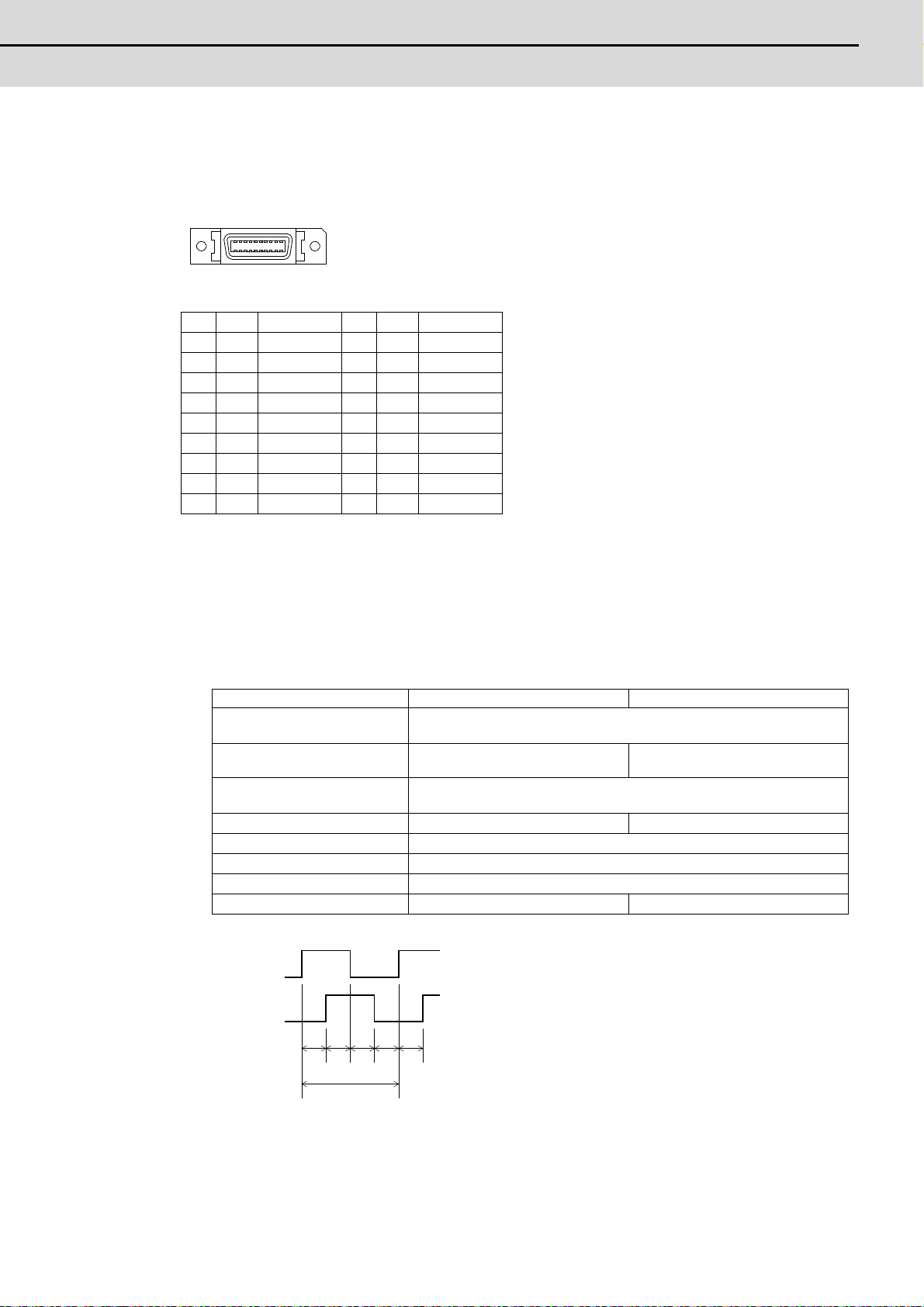
E70 Series Connection Manual
2.5 Operation Panel I/O Unit
(10) Manual pulse generator input 2ch (5V and 12V) (MPG)
10 1
20 11
T
b da c e
A(B) phase
B(A) phase
5V manual pulse generator and 12V manual pulse generator can be connected to this connector.
Connect the synchronous feed encoder to the ENC connector of the control unit.
1 GND 11 GND
2 reserve 12 reserve
3 IHA2A 13 IHA2B
4 IHA1A 14 IHA1B
5 GND 15 GND
6 O 12VDC 16 O12VDC
7 reserve 17 reserve
8 reserve 18 reserve
9 reserve 19 reserve
10 O5VDC 20 O5VDC
* Connect connector case with FG pattern.
<Cable side connector type>
Plug: 10120-3000VE
Shell: 10320-52F0-008
Recommended manufacturer: 3M
<Specification of input part>
5V manual pulse generator 12V manual pulse generator
Number of pulse phases
Signal output of manual pulse
generator
Signal voltage
Power supply voltage 5VDC±10% 12VDC±10%
Current consumption 100mA or less
Number of pulses per rotation 25 pulse/rev,100 pulse/rev
Input frequency (rotation speed) 1kHz or less (40r/s or less for 25pluse/rev, 10r/s or less for 100pluse/rev)
Cable length 20m or less 50m or less
Two phases (A phase, B phase, a phase difference 90 degrees)
(Refer to the waveform below.)
Voltage output, open collector output Open collector output
H level 3.5V to 5.25V
L level 0V to 0.5V
a.b.c.d.e: A phase or B phase rising edge (falling edge) phase difference = T/4 ± T/10
T: A or B phase cycle
33
Page 59

2 General Specifications
MITSUBISHI CNC
<Input/output circuit>
0V
+5V
4
3
14
13
10
20
1
11
0V
+5V
+5V
+5V
0V
0V
0V
6
16
+12V
+12V
5V
12V
HA1A
HA2A
HA1B
HA2B
Connector
pin No.
Signal
input
Power
output
Power
output
Control
unit
13
(11) Remote I/O unit I/F (RIO3)
1 I/O TXRX3
2 I/O TXRX3*
3 0V(GND)
<Cable side connector type>
Connector: 1-178288-3
Contact: 1-175218-2 x3
Recommended manufacturer: Tyco Electronics
Refer to the following chart for the maximum number of connecting stations and I/O points.
Operation panel I/O unit type
FCU7-DX621/DX721/DX731
(Note) Refer to the section "General Specifications: Remote I/O Unit" for the number of occupying stations and I/
(12) Control unit I/F (CG71)
O points of remote I/O units.
FCU7-DX711
Max. number of stations
(RIO3 connection)
4 stations
(stations 3rd to 6th can be used)
3 stations
(stations 4th to 6th can be used)
Max. number of I/O points
(RIO3 connection)
128 points/128 points
96 points/96 points
34
Page 60

E70 Series Connection Manual
2.5 Operation Panel I/O Unit
(13) LED
Name Function At fault Conditions
3VON 3VDC input check Not lit (1) Disconnection between control unit and operation panel I/O unit
5VON 5VDC input check Not lit
PACKETNG
RIO1
12VON
DOCOM 24VDC input check Not lit
RIO communication
status check
RIO communication
status check
For manual pulse
generator
Lit (Red)
Not lit
Not lit Short circuit of manual pulse generator cable
(1) Disconnection between control unit and operation panel I/O unit
(2) Short circuit of manual pulse generator cable
(1) Partial disconnection between control unit and operation panel I/O unit
(2) Miswiring of extended I/O unit to RIO3
(1) Disconnection of 24V input
(2) Disconnection of protection fuse on the operation panel I/O unit
35
Page 61

2 General Specifications
MITSUBISHI CNC
2.6 Remote I/O Unit
The following four types of signals can be input/output from the remote I/O unit (FCUA-DX1x1) according to the type and
No. of contacts. Use serial link connections to connect the unit with the control unit or the operation panel I/O unit.
Multiple remote I/O units can be used as long as the total number of occupied stations is eight or less.
Classification Type Components Remarks
DI 24V/0V common input
DO Source output
DI 24V/0V common input
DO Source output
DI 24V/0V common input
DO Source output
AO Analog output
DI 24V/0V common input
DO Source output
AI Analog input
AO Analog output
FCUA-DX101 RX312
FCUA-DX111 RX312+RX322-1
FCUA-DX121 RX312+RX322
FCUA-DX141 RX312+RX341
DI: 32-points 24V/0V common type
(photo coupler insulation)
DO: 32-points source type (non-insulation)
Number of occupied stations: 1
DI: 64-points 24V/0V common type
(photo coupler insulation)
DO: 48-points source type (non-insulation)
Number of occupied stations: 2
DI: 64-points 24V/0V common type
(photo coupler insulation)
DO: 48-points source type (non-insulation)
AO: 1 point
Number of occupied stations: 2
DI: 32-points 24V/0V common type
(photo coupler insulation)
DO: 32-points source type (non-insulation)
AI: 4 points
AO: 1 point
Number of occupied stations: 2
36
Page 62
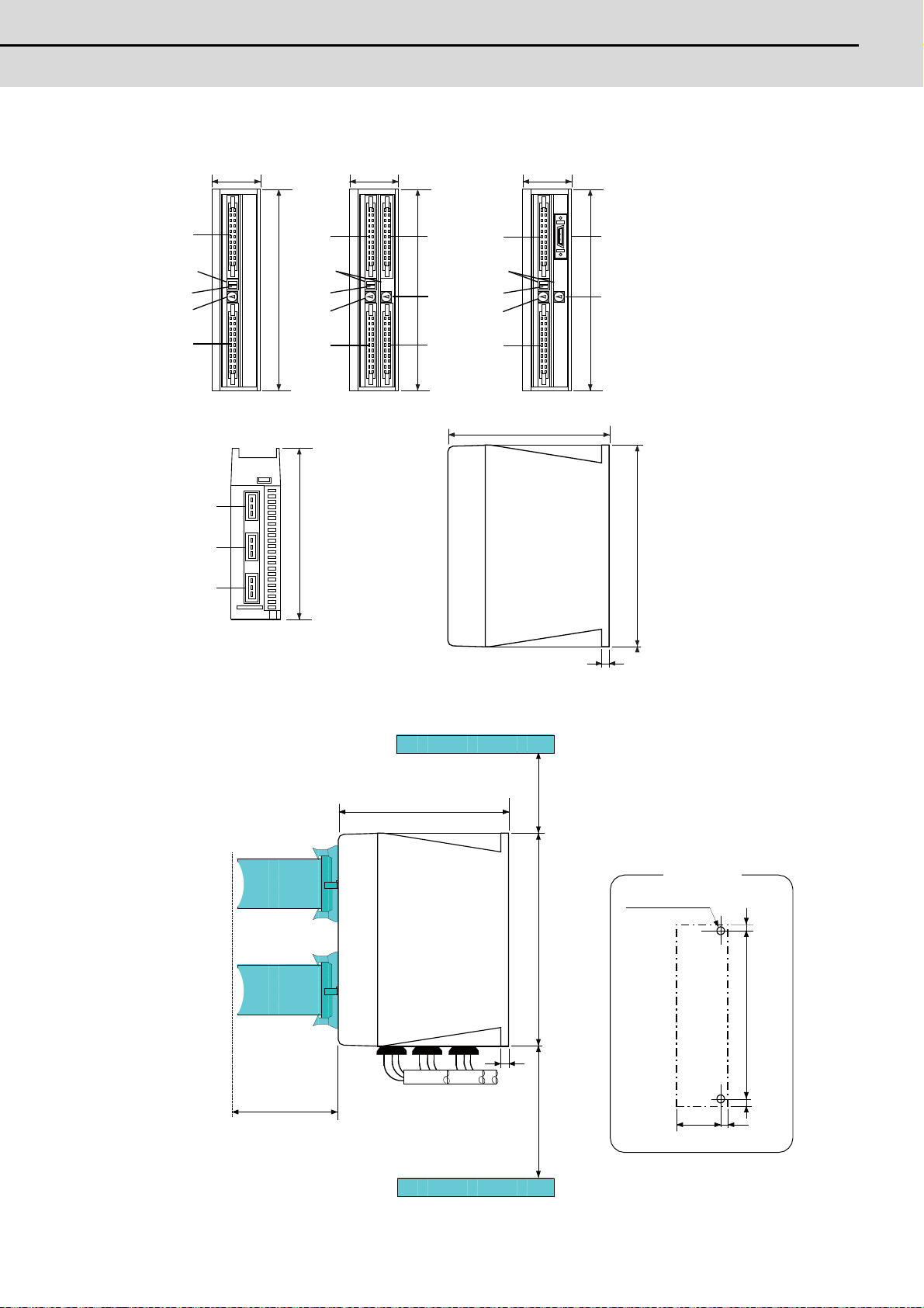
E70 Series Connection Manual
2.6 Remote I/O Unit
Dimension and names of parts
(2)
(4)
(5)
(8)
(9)
(10)
(1)
(7)
(3)
(7)
(7)
(1)
(7)
(3)
(1)
(7)
(3)
(DX101) (DX141)(DX111/DX121)
6
135
135
40
40 40
168
168
168
168
(6)
(11)
(6)
(11)
(6)
(11)
[Front view]
(Front)
(Rear)
[Side view][Bottom view]
70
6
135
168150 100
634
156
6
6
2-M5 screw
Mounting hole
Bottom
To p
<Installation dimension drawing>
37
Page 63

2 General Specifications
MITSUBISHI CNC
(1) Machine input (DI-L)
A3,B3
A3,B3
R
0V
FG
COM
0V
FG
COM
R
DI-L / DI-R
2.2k
DI-L / DI-R
2.2k
24VDC(+)
Control
circuit
(Machine side)
Stabilized
power supply
External contact
Input voltage
Input resistor
24VDC(+)
Input voltage
24V common
0V common
Control
circuit
(Machine side)
Stabilized
power supply
External contact
Input resistor
T1T1
T2
T4T3
GND
+24V
(E)
(I)
(2) Machine input (DI-R)
Both 24V common and 0V common connections are allowed in the digital signal input circuit.
Follow the wiring diagram below for each type.
Input circuit
Input conditions
The input signals must be used within the following condition ranges.
24V common 0V common
1 Input voltage at external contact ON 6V or less 18V or more, 25.2V or less
2 Input current at external contact ON 9mA or more
3 Input voltage at external contact OFF 20V or more, 25.2V or less 4V or less
4 Input current at external contact OFF 2mA or less
5 Input resistance Approx. 2.2kΩ
6 Tolerable chattering time (T1) 3ms
7 Input signal holding time (T2) 40ms or more (Note)
input circuit operation delay time (T3
8
and T4)
3 to 16ms
9 Machine side contact capacity 30V or more, 16mA or more
(Note) Input signal holding time: The guide is 40ms or more. The input signal will not be recognized unless
it is held for the ladder processing cycle time or longer.
38
Connection to 24V common input Connection to 0V common input
T2
(E)
T1T1
+24V
GND
(I)
T4T3
(E) : External signal, (I) : Internal signal
Page 64

E70 Series Connection Manual
2.6 Remote I/O Unit
(3) Machine output (DO-L)
R
RA
DO-L/DO-R
PL
Source type (DX1x1)
24VDC(+)
Control
circuit
(Machine side)
(4) Machine output (DO-R)
Use within the specification ranges shown below.
Output circuit
Output conditions
Insulation method Non-insulation
Rated load voltage 24VDC
Max. output current 60mA/point
Output delay time 40μs
(Note 1) When using an inductive load such as a relay, always connect a diode (voltage resistance 100V or more,
100mA or more) in parallel to the load.
(Note 2) When using a capacitive load such as a lamp, always connect a protective resistor (R=150Ω) serially to
the load to suppress rush currents. (Make sure that the current is less than the above tolerable current
including the momentary current.)
39
Page 65

2 General Specifications
MITSUBISHI CNC
[Outline of analog signal output circuit]
The analog signal output circuit can be used only for FCUA-DX121.
Output circuit
R
220
AO
AO*
Output conditions
Output voltage 0V to ±10V (±5%)
Resolution 12bit (±10V × n/4096) (Note)
Load conditions 10kΩ load resistance
Output impedance 220Ω
R
DAC
0V(RG)
(Note) n=(2
0
to 211)
CAUTION
1. When using an inductive load such as a relay, always connect a diode in parallel to the load.
2. When using a capacitive load such as a lamp, always connect a protective resistor serially to the load to
suppress rush currents.
40
Page 66

E70 Series Connection Manual
2.6 Remote I/O Unit
(5) Analog signal input/output (AIO)
DAC
R
220
R
AO
AO*
0V(RG)
ADC
150
AI
AI*
0V(RG)
(a) Outline of analog signal output circuit
The analog signal output circuit can be used only for FCUA-DX141.
Output circuit
Output conditions
Output voltage 0V to ±10V (±5%)
Resolution 12bit (±10V × n/4096) (Note)
Load conditions 10kΩ load resistance
Output impedance 220Ω
(Note) n=(20 to 211)
(b) Outline of analog signal input circuit
The analog signal input circuit can be used only for FCUA-DX141.
Input circuit
Input conditions
Max. input rating ±15V
Resolution |-10 to +10V| / 4096 = 4.88mV
Precision Within ±25mV
AD input sampling time 14.2ms(AI0)/ 42.6ms(AI1 to 3)
41
Page 67
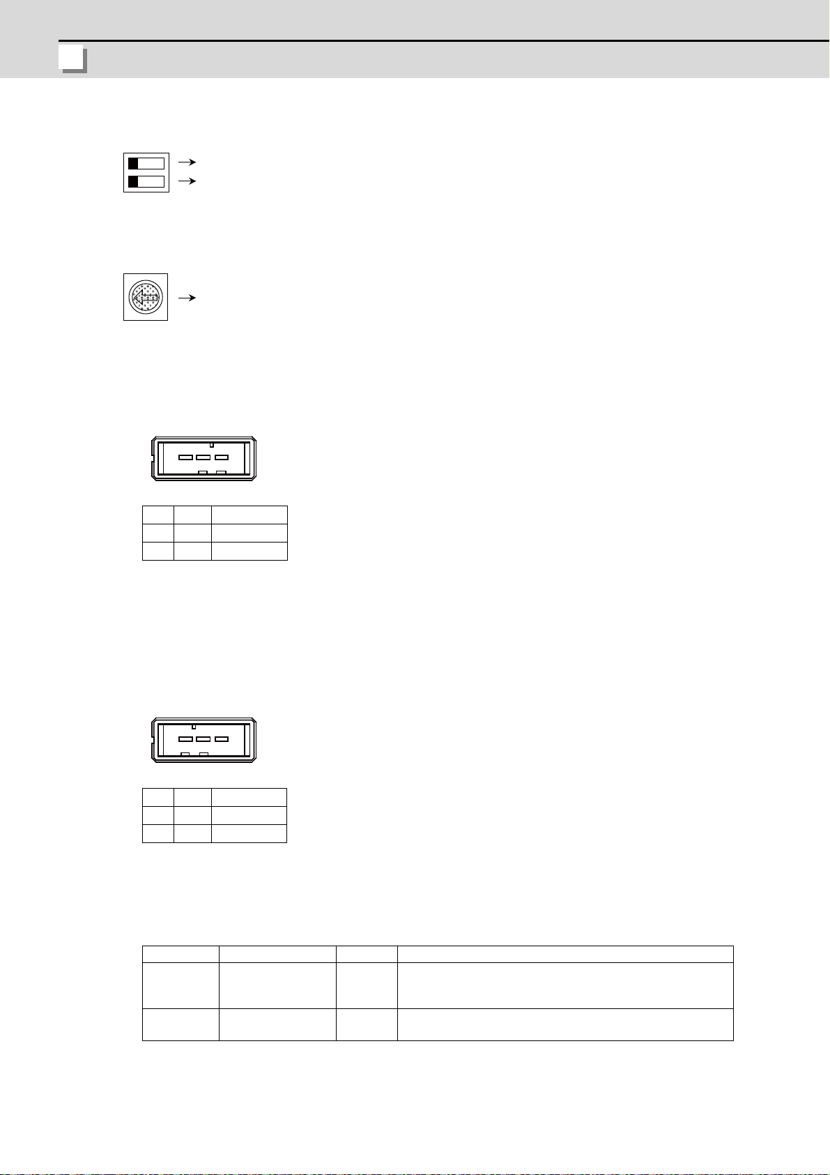
2 General Specifications
MITSUBISHI CNC
(6) Transfer speed changeover switch (DS)
A
Selection of station No.
13
13
Not used
Not used
(7) Station No. changeover switch (CS)
4
3
5
2
6
1
7
0
8
F
9
E
D
B
C
(8) Remote I/O unit I/F #1 (RIO1)
(9) Remote I/O unit I/F #2 (RIO2)
1 I/O TXRX
2 I/O TXRX*
3 0V
<Cable side connector type>
Connector: 1-178288-3
Contact: 1-175218-2 x3
Recommended manufacturer: Tyco Electronics
(10) 24VDC input (DCIN)
1 I+24V
2 0V
3 FG
<Cable side connector type>
Connector: 2-178288-3
Contact: 1-175218-5 x3
Recommended manufacturer: Tyco Electronics
(11) LED
Name Function At fault Conditions
POWER
Green (UP)
ALM
Red (DOWN)
Internal output
voltage(5VDC) check
RIO communication
status check
Not lit
Lit
(1) Failure of 24VDC input
(2) Fuse is disconnected
(3) Failure of internal voltage output in I/O unit
(1) Partial disconnection between control unit and remote I/O unit
(2) Miswiring of connected remote I/O unit
42
Page 68

E70 Series Connection Manual
2.7 External Power Supply Unit
2.7 External Power Supply Unit
220
230
2-R3
230
208
AC IN
ON/OFF SW
ON/OFF
POWER
DC OUT
65
30
6
6
130
FAN ALARM
(1)
(2)
(3)
(5)
(4)
Item PD25
Input power voltage
Output current 3A
Dimension 130mm × 65mm × 230mm
Mass 1.5kg
Output holding time 300ms
(Note 1) PD25 will not be turned ON by the ON/OFF switch immediately after the power OFF. Wait at least 2
seconds, and then turn the power ON.
(Note 2) The power supply configuration for NC devices depends on the machine. Appropriate circuit protector
must be selected by machine builder according to the load of the machine.
(Note 3) PD25 does not comply with 100VAC.
Dimension and names of parts
[PD25]
200 to 230VAC
+10%-15%
50/60Hz±1Hz
<Mounting direction and clearance>
Mount the external power supply unit vertically and so that it is visible from the front. Provide space for heat
dissipation and ventilation.
100mm
20mm 20mm
100mm
43
Page 69
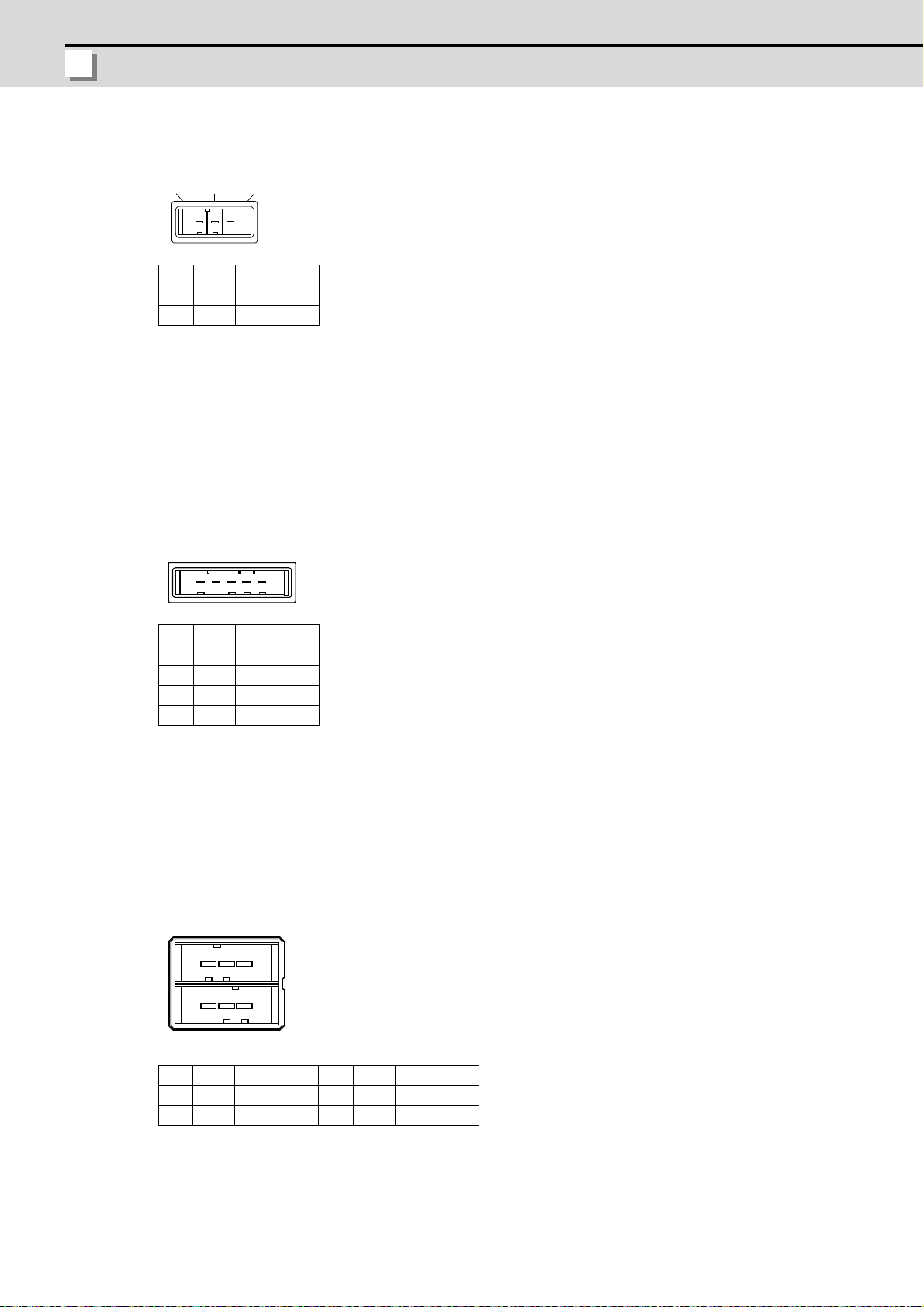
2 General Specifications
MITSUBISHI CNC
(1) AC power input (ACIN)
123
15
A3A1
B3B1
1 IACIN N
2 IACIN H
3 FG
<Cable side connector type>
Connector: 2-178128-3
Contact: 1-175218-5 × 3
Recommended manufacturer: Tyco Electronics
(2) ON/OFF switch (ON/OFF SW)
Switch ON (upward): 24VDC output
Switch OFF (downward): 24VDC output OFF
(3) ON/OFF input (ON/OFF)
1 NC
2 IP-OFF
3 0V
4 0V
5 IP-ON
<Cable side connector type>
Connector: 1-178288-5
Contact: 1-175218-5 × 4
Recommended manufacturer: Tyco Electronics
(4) LED (POWER)
Green light at +24V output
(5) 24VDC output (DCOUT)
1A OACFAIL 1B O +24V
2A 0V 2B 0V
3A NC 3B FG
<Cable side connector type>
Connector: 3-178127-6
Contact: 1-175218-5 (for AWG16) × 3, 1-175217-5 (for AWG22) × 2
Recommended manufacturer: Tyco Electronics
44
Page 70

E70 Series Connection Manual
2.8 Manual Pulse Generator
2.8 Manual Pulse Generator
3- M4Gasket
Above size only
72 at equal pitch
Panel cut diameter
stud
Index
<Panel cut drawing>
at equal pitch
<Outline dimension drawing>
[UFO-01-2Z9]
5V Manual Pulse Generator (100 pulse/rev)
Produced by NIDEC NEMICON CORPORATION
45
Page 71

2 General Specifications
MITSUBISHI CNC
[HD60C]
3.6
16 2 4 2 7
0.5
77
0.5
80 1
60
0.560 0.5
L10
8.89 7.60
12V 0V A B
t2.0
3-M4
Installation of screws
stud bolt
Packing
other than M3 x 6
not possible
3- 4.8
62
+2
0
72
0. 2
120°
(Divide equally
by three)
<Panel cut dimension drawing>
12V Manual Pulse Generator (25 pulse/rev)
46
Page 72

E70 Series Connection Manual
2.9 Synchronous Feed Encoder
2.9 Synchronous Feed Encoder
19. 5
102
135
5
3
33
2
68
28
20
56
68
4- 5.4
21m
m
14. 3
0
-0. 11
1. 1 5
+0. 14
0
1. 1 5
+0. 14
0
2
26
16
50
15
-0. 006
-0.017
-0. 009
-0.025
2
5
-0.012
-0.042
3
+
0
.
1
0
6
8
5
6
50
-
0
.
0
0
9
-
0
.
0
2
5
Caution plate
hole
Enlarged drawing of key
Valid depth of key groove is
Cross section BB
F
J
T
G
L
K
M
H
C
D
E
R
S
P
N
B
A
Dimension and names of parts
[OSE-1024-3-15-68]
Connector pin assignment
Pin Function Pin Function
A A phase K 0V
B Z phase L C B phase M D - N A phase
E Case grounding P Z phase
F - R B phase
G - S H +5V T J -
47
Page 73

2 General Specifications
MITSUBISHI CNC
2.10 MITSUBISHI CNC Machine Operation Panel
260
17
60
140
(Space required for wiring)
260
244
250
124
140
4-M3
130
0.3
0.3
Screw
(Unit outline)
(Unit outline)
(Square hole)
2.10.1 MITSUBISHI CNC Machine Operation Panel A
Outline dimension
[FCU7-KB921 (MITSUBISHI CNC machine operation panel A)]
<Panel cut dimension drawing>
48
Page 74
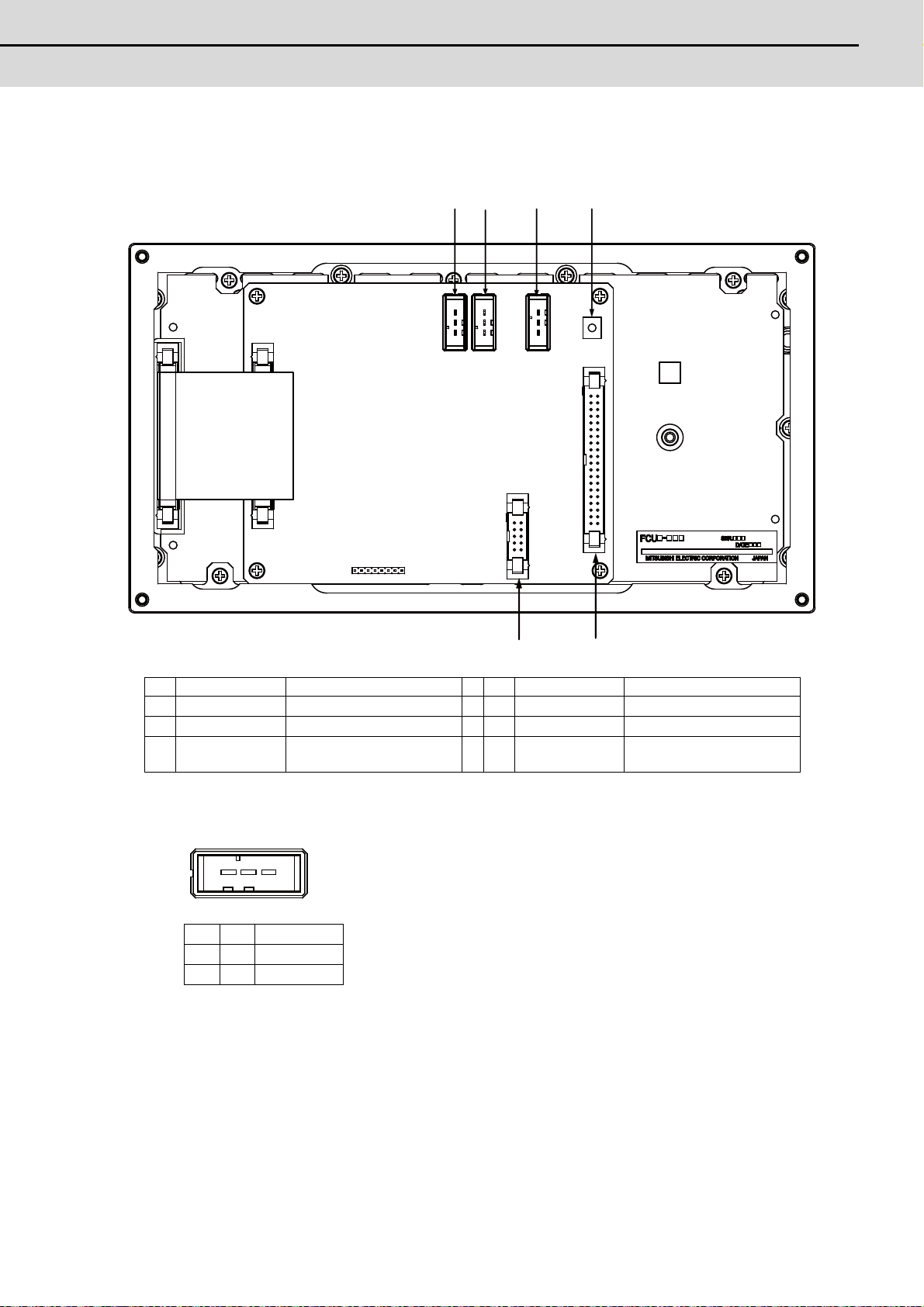
E70 Series Connection Manual
2.10 MITSUBISHI CNC Machine Operation Panel
Connector
(1)
(2)
(3)
(4)
(5)
(6)
13
No. Connector name Function No. Connector name Function
(1) DCIN 24VDC input (4) FG FG terminal
(2) DCOUT 24VDC output (5) EXT Relay wiring
(3) RIOIN Remote I/O (6) SUBP
Mahine operation panel B
switch
(1)(2) 24VDC input/output (DCIN/DCOUT)
1 I/O +24V
2 -0V
3 -FG
<Cable side connector type>
Connector: 2-178288-3
Contact: 1-175218-5 x3
Recommended manufacturer: Tyco Electronics
49
Page 75
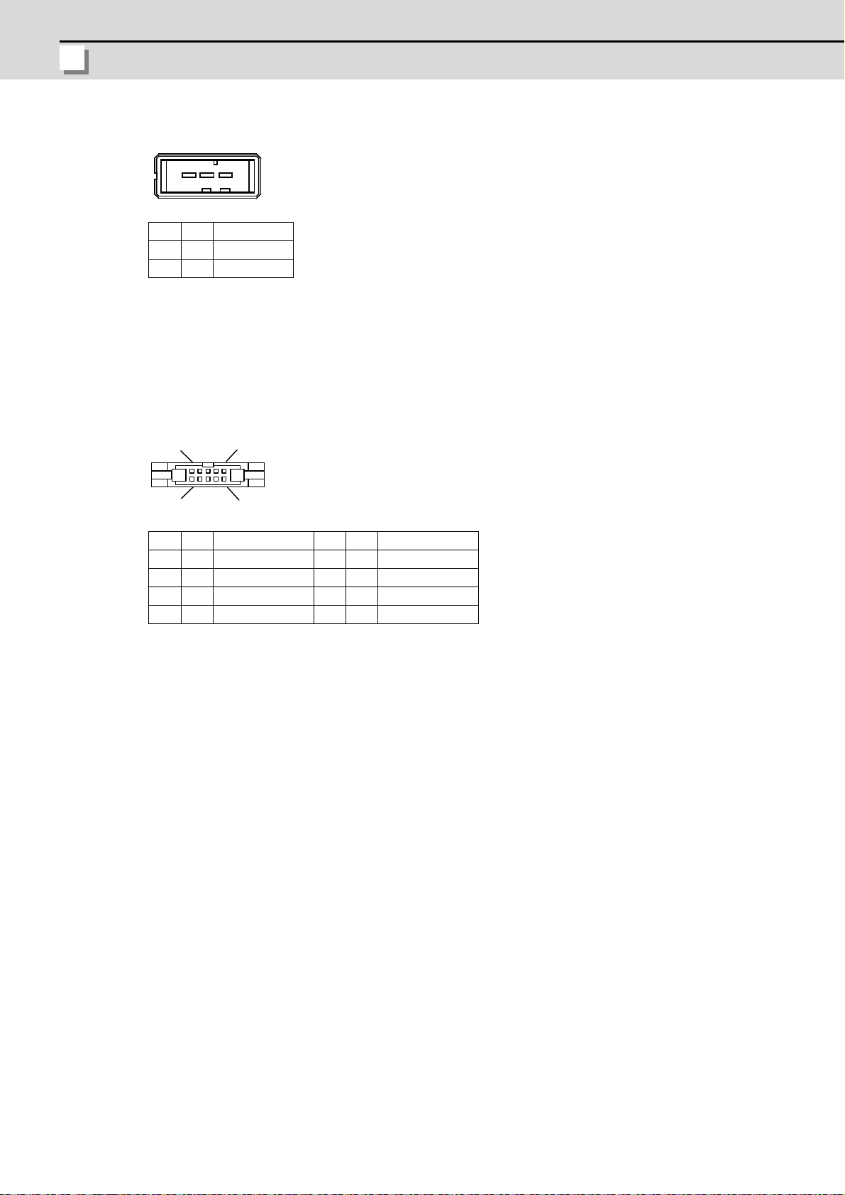
2 General Specifications
MITSUBISHI CNC
(3) Remote I/O connected connector (RIOIN)
13
1 I/O TXRX
2 I/O TXRX*
3 -0V
<Cable side connector type>
Connector: 1-178288-3
Contact: 1-175218-2 x3
Recommended manufacturer: Tyco Electronics
(4) FG terminal (FG)
(5) Relay wiring (EXT)
A5
B5
B05 - A05 B04 O Relay EMGCOM A04 O Relay EMG
B03 O Relay 6 A03 O Relay 5
B02 O Relay 4 A02 O Relay 3
B01 O Relay 2 A03 O Relay 1
A1
B1
<Cable side connector type>
Connector: HIF3BA-10D-2.54C
Contact: HIF3-2428SC
Recommended manufacturer: Hirose Electric
50
Page 76
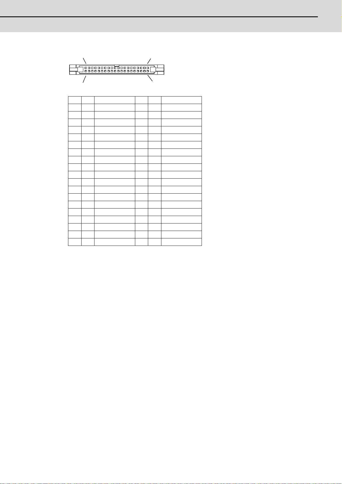
E70 Series Connection Manual
2.10 MITSUBISHI CNC Machine Operation Panel
(6) Machine operation panel B switch (SUBP)
A1
B1
A20
B20
B20 I Relay EMGCOM A20 I Relay EMG
B19 I Relay 6 A19 I Relay 5
B18 I Relay 4 A18 I Relay 3
B17 I Relay 2 A17 I Relay 1
B16 - 0V A16 I Spare SW(X75)
B15 - 0V A15 I Spare SW(X74)
B14 - 0V A14 I Spare SW(X73)
B13 - 0V A13 I Selector SW(X72)
B12 - A12 I G(X71)
B11 I F(X6D) A11 I E(X6F)
B10 I D(0V) A10 I C(X70)
B09 I B(X6E) A09 I A(X6C)
B08 - A08 I G(X6B)
B07 I F(X67) A07 I E(X66)
B06 I D(0V) A06 I C(X6A)
B05 I B(X68) A05 I A(X66)
B04 - A04 I G(X65)
B03 I F(X61) A03 I E(X63)
B02 I D(0V) A02 I C(X64)
B01 I B(X62) A01 I A(X60)
<Cable side connector type>
Connector: HIF3BA-40D-2.54C
Contact:HIF3-2428SC
Recommended manufacturer: Hirose Electric
51
Page 77

2 General Specifications
MITSUBISHI CNC
D
G
C
E
B
F
A
[SUBP]
X60
X61
X62
X63
X64
X65
X66
X67
X68
X69
X6A
X6B
B02
A01
B03
B01
A03
A02
A04
+5V
D
G
C
E
B
F
A
B06
A05
B07
B05
A07
A06
A08
+5V
(RSW2)
X6D
X6E
X6F
X70
X71
D
G
C
E
B
F
A
B10
A09
B11
B09
A11
A10
A12
+5V
1kΩ
X6C
R
R
R
R
R
R
R
R
R
R
R
R
R
R
R
R
R
R
21 position
(RSW1)
Machine Operation Panel
I/F PCB HN232
Machine operation panel B
(FCU7-KB926)
Rotary Switch
Real gray code
(For cutting override)
Rotary Switch
(For spindle override)
8 position
Real gray code
Rotary Switch
(Spare)
(a) Wiring of machine operation panel B
<Wiring of rotary switch (SUBP)>
52
(Note1) Use the special lead wire with a connector for wiring of rotary switch.
Lead wire with a connector: ACX011-705 (7 terminals, 0.5m) Fuji Electric
(Note2) A09 to 12 and B09 to 11 of SUBP are spares, so they do not need wiring.
(Note3) Select a rotary switch which guarantees 5V/1mA.
(Note4) Length of cables must be 0.5m or shorter.
(Note5) The numbers in the above diagram do not in dicate the actual device numbers.
Page 78
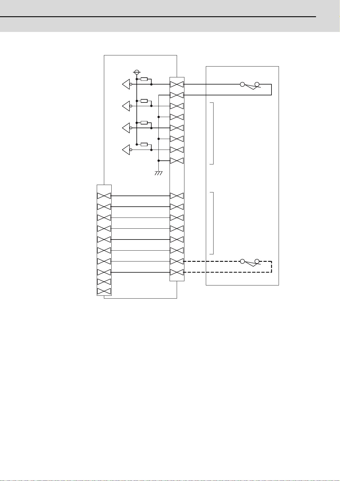
E70 Series Connection Manual
2.10 MITSUBISHI CNC Machine Operation Panel
<Wiring of other switches (SUBP)>
Machine Operation Panel
I/F PCB HN232
+5V
R
X72
R
X73
R
X74
R
X75
[EXT]
A01
1kΩ
[SUBP]
A13
B13
A14
B14
A15
B15
A16
B16
A17
Machine operation panel B
(FCU7-KB926)
Selector Switch
(For memory protection)
2 notch Key shape
2c Manual return type
Switch input spare
(3 points)
EMG
B01
A02
B02
A03
B03
A04
B04
A05
B05
B17
A18
B18
A19
B19
A20
B20
Spare for signal relay
Push down switch
(For emergency stop)
Push Lock -
Turn Reset
2a2b contact
(Note1) Wirings for selector switches must be directly sold ered to terminals or use tab terminals (110
series).
(Note2) When wiring the emergency stop switch, the crimp terminal must be fastened with thread.
(Note3) For NCs whose control unit and display unit are integrated, wire the emergency stop switch
directly to the EMG connector of the control unit. (Use F120 cable)
And for NCs whose control unit and display are separated, relay it by the machine operation
panel I/F PCB HN232.
(Note4) Select a rotary switch which guarantees 5V/1mA.
(Note5) Length of cables must be 0.5m or shorter.
(Note6) The numbers in the above diagram do not indicate the actual device numbers.
53
Page 79

2 General Specifications
MITSUBISHI CNC
<Connection when the selector SW has 3 notches>
[SUBP]
X72
X73
X74
X75
B13
A13
A14
A15
A16
B14
B15
B16
+5V
R
R
R
R
Selector SW
3 notch
2a2b Manual return type
<Connection when relaying wiring to control panel>
[EXT]
PON
PON CO M
(0V)
POF F
POF FC OM
(0V)
EMG
EMGCOM
(24VDC)
EMG
EMGCOM
(24VDC)
A01
B01
A02
B02
A03
B03
A04
B04
A05
B05
A17
B17
A18
B18
A19
B19
A20
B20
P-ON
P-OFF
Push button SW
(For emergency stop)
Push Lock Turn Reset
2a2b contact
Connection with
P-ON/OFF Switch
Connection using two contacts
of emergency switch
54
Page 80

E70 Series Connection Manual
2.10 MITSUBISHI CNC Machine Operation Panel
2.10.2 MITSUBISHI CNC Machine Operation Panel B
140
140
32
70
2
48
(Space required for wiring)
140
124
130
124
140
4-M3
130
0.3
0.3
Screw
(Unit outline)
(Unit outline)
(Square hole)
Outline dimension
[FCU7-KB926 (MITSUBISHI CNC machine operation panel B)]
<Panel cut drawing>
55
Page 81

2 General Specifications
MITSUBISHI CNC
Connector
No. Switch No. Switch
(1) Memory protection switch (3) Spindle override (RSW2)
(2) Emergency stop button (4) Cutting override (RSW1)
(1) Memory protection switch
(1)
(3)
<Contact configuration>
(2)
(4)
Contact 2 Contact 1
C - Contact 1(Common)
NO O Contact 1(A contact)
NC O Contact 1(B contact)
C - Contact 2(Common)
NO O Contact 2(A contact)
NC O Contact 2(B contact)
<Switch type>
Switch: HA1K-2C2B
Recommended manufacturer: IDEC
Connection: Terminal (#110 type)
56
Page 82

E70 Series Connection Manual
2.10 MITSUBISHI CNC Machine Operation Panel
(2) Emergency stop button
AG
13 O Contact 1(A contact)
14 O Contact 1(A contact)
21 O Contact 2(B contact)
22 O Contact 2(B contact)
33 O Contact 3(A contact)
34 O Contact 3(A contact)
41 O Contact 4(B contact)
42 O Contact 4(B contact)
<Switch type>
Switch: XA1E-BV422MR
Recommended manufacturer: IDEC
Connection: Thread terminal (M3)
(3) Spindle override (RSW2)
A O Output signal 1
B O Output signal 3
C O Output signal 5
D - Common terminal
E O Output signal 4
F O Output signal 2
G --
<Switch type>
Switch: AC09-GX0/7L3B02
Recommended manufacturer: Fuji Electric
Connection: Connector
<Switch side connector type>
Connector: IL-7P-S3EN2
Recommended manufacturer: Japan Aviation Electronics
<Cable side connector type>
Connector: IL-7S-S3L-(N)
Contact: L-C2-10000
Recommended manufacturer: Japan Aviation Electronics
57
Page 83

2 General Specifications
MITSUBISHI CNC
(4) Cutting override (RSW1)
AG
A O Output signal 1
B O Output signal 3
C O Output signal 5
D - Common terminal
E O Output signal 4
F O Output signal 2
G O Output signal 6
<Switch type>
Switch: AC09-GY0/20L3B02
Recommended manufacturer: Fuji Electric
Connection: Connector
<Switch side connector type>
Connector: IL-7P-S3EN2
Recommended manufacturer: Japan Aviation Electronics
<Cable side connector type>
Connector: IL-7S-S3L-(N)
Contact: IL-C2-10000
Recommended manufacturer: Japan Aviation Electronics
58
Page 84

E70 Series Connection Manual
2.11 Exclusive CF Cards for MITSUBISHI CNC
2.11 Exclusive CF Cards for MITSUBISHI CNC
Item FCU7-CF256M FCU7-CF002G
Capacity 256MB 2GB
Operation-guaranteed
temperature
NAND Flash SLC (Note)
(Note) SLC stan ds for Single Level Cell, and it stores one bit data in each memory cell.
This provides longer life span and high product reliability in comparison with MLC (Multi Level Cell), which is
commonly applied to CF cards.
2.11.1 Precautions for Use of Commercially Available CF Cards
Mitsubishi is unable to guarantee the machine operation when a commercially avai lable CF card or SD memory card
(SD-CF adapter is required) is used. In that case, performance check must be made carefully by machine tool builder.
(1) Commercially available CF cards may not be compatible with MITSUBISHI units or suitable FA environment for
temperature- or noise-wise. In case of using it, careful performance check must be required by the machine tool
builder.
(2) When inserting/removing a commercially available CF card, turn the MITSUBISHI device’s power OFF to avoid any
troubles. If a card must be inserted and removed while the power is ON, make sure to take sufficient time (approx.
ten seconds or more) between the insertion and removal.
(3) Do not pull out the card or turn OFF the power during access to the CF card. Failure to observe this could cause the
memory contents to be erased. In case of emergency, always perform backups by having your important data
duplicated, etc. as MITSUBISHI will not guarantee the broken or lost data.
-40 ℃ to +85 ℃
59
Page 85

2 General Specifications
MITSUBISHI CNC
60
Page 86

61
3
Installation
Page 87

3 Installation
MITSUBISHI CNC
3.1 Heat Radiation Countermeasures
W≤ W1
ΔT
≤
10°C
ΔT>10°C
Calculate total heat radiation of each
mounted unit (W)
Comparison of W and W1
Collection of internal temperature rise
distribution data
Mounting design
Improvements
Completion
Selection of heat exchanger
Evaluation
Calculate cooling capacity of
operation panel (W1)
Please refer to the following method for heat radiation countermeasures.
Example of heat radiation countermeasures
<Hypothetical conditions>
(1) Average internal temperature of operation panel: T ≤ 55°C
(2) Peripheral temperature of operation panel : Ta ≤ 0°C to 45°C
(3) Internal temperature rise value : ΔT = T - Ta (max) = 10°C
Procedures for heat design and verification
W>W1
<Supplement>
(1) Refer to "General Specification" for the heat generated by each unit.
(2) Enclosed cabinet (thin steel plate) cooling capacity calculation equation
W1 = U × A × ΔT
U: 6 W/m
2
A: Effective heat radiation area (m
ΔT: Internal temperature rise value (10°C)
(Caution) 8 W/m
(3) Points of caution for heat radiation countermeasures when designing mounting state
- Consider convection in operation panel (eliminate heat spots)
- Collect hot air at suction port of heat exchanger in operation panel.
(4) Criterion for internal temperature rise distribution data
62
ΔT (average value) ≤ 10°C
ΔTmax (maximum value) ≤ 15°C
R (inconsistency ΔTmax - ΔTmin) ≤ 6°C
(Evaluate existence of heat spots)
°C
2
) (Area where heat can be radiated from operation panel)
2
°C can be applied only when the operation panel is so small that the internal
temperature stays uniform.
Page 88

E70 Series Connection Manual
3.1 Heat Radiation Countermeasures
The following shows an example of calculation applied to heat radiation countermeasures for the operation panel when
8.4-type display unit is used. Because heat will accumulate in the upper portions of the unit, install an agitating fan as
required.
Display Unit
200
260 140
600
(Agitating fan)
500
120
63
Page 89

3 Installation
MITSUBISHI CNC
Calculation example of panel internal heating value
(1) Calculation of unit heating value
Heating value (W)
Total heating value of units (W):
28W (= control unit + display unit + keyboard unit + operation panel I/O unit)
Total heating value (W) by machine input (D1):
5.6W (=24V (total heating value when the 32 points are simultaneously turned ON) × 7.3mA × 32)
... 24V (current consumption per point of the operation panel I/O unit DI) divided by 3.3kΩ ≈ 7.3mA
Total heating value W = 33.6W (28 + 5.6)
(2) Calculation of operation panel coolin g ca pa c ity
Tolerance value for temperature rise ( ⊿ t)
Panel internal temperature (according to each unit's specification) T ≤ 55C°
Panel peripheral temperature (according to machine's specification) Ta ≤ 45C°
Tolerance value for internal temperature rise ⊿ T = 10C° (T - Ta)
Heat radiation area (A)
The surface of the molded unit, which has lower radiation capacity than the base plate surface, should be
excluded for the heat radiation area in principle. The bottom of the operation panel, which has difficulty in
radiating due to the temperature distribution, should also be excluded for the heat radiation area in
principle.
2
Heat radiation area A = 0.71mm
(≈ 0.6 × 0.12 + 0.6 × 0.5 × 2 - (0.26 + 0.14) × 0.2 + 0.12 × 0.5 × 2)
(Top surface) (Front, rear surface) (Unit surface) (Both sides surface)
Operation panel cooling capacity (W1)
Calculate the cooling capacity to keep the temperature rise in the operation panel less than 10°C.
Cooling capacity W1 = 42.6W (6 × A × ⊿ T)
(3) Comparison of heating value and operation panel cooling capacity
The operation panel cooling capacity is over the heating value, which presumed no need to install the heat
exchanger.
(4) Confirmation with the actual machine
The result of the calculation above is only a rough indication. The actual temperature rise may differ according
to the structure of the operation panel. Be sure to confirm the temperature rise value in the operation panel
when the machine is running.
64
Page 90

E70 Series Connection Manual
3.2 Noise Countermeasures
3.2 Noise Countermeasures
Short bar
AC input
Stabilized
power supply
Main grounding plate
for electric cabinet
FG cable
FG cable
F070 cable
Control unit
Operation panel I/O unit
24VDC
3.2.1 Connection of FG (Frame Ground)
The frame should basically be grounded at one ground point.
Connect the control unit and operation panel I/O unit's 0V (RG) to the FG on the +24V stabilized power supply.
(Note) "24VDC" represents (+) side of 24V stabilized power supply, while "0V(RG)" represents (-) side. "FG" (Frame
Ground) corresponds to the general expression "PE" (Protective Earth).
65
Page 91

3 Installation
MITSUBISHI CNC
3.2.2 Shield Clamping of Cables
E
Contact
Spark
killer
Coil
Spark
killer
The shield cables connected to the units must be properly connected to the ground with clamp fittings and the like in
order to stabilize the system's operation while preventing malfunctioning due to exogenous noise. (Refer to "EMC
Installation Guidelines: EMC Countermeasure Parts: Shield Clamp Fitting".)
3.2.3 Connecting Spark Killers
Connect a spark killer on the coil or the contact in parallel for noise countermeasures.
Use spark killers which are 0.33 to 0.1μF, 10 to 120Ω.
66
Page 92

E70 Series Connection Manual
3.3 Unit Installation
3.3 Unit Installation
Fixing screws (4)
3.3.1 Display Unit
Mount the display unit with four fixing screws.
(Note) Refer to "General Specifications: Display Unit" for the panel cut dimension drawing and the screw hole
position.
67
Page 93

3 Installation
MITSUBISHI CNC
3.3.2 Keyboard Unit
Fixing screws (4)
NCKB
Connector
Fixing screw (4 pcs.)
M3x25
(with plain washer and spring washer)
Mount the keyboard unit with four fixing screws.
(Note 1) Refer to "General Specifications: Keyboard Unit" for the panel cut dimension drawing and the screw hole
position.
(Note 2) A clear protective film covers the sheet keys of the keyboard at the time of shipment. Make sure to remove the
sheet before use.
3.3.3 Operation Panel I/O Unit
Mount the operation panel I/O unit on the back of the keyboard unit with four fixing screws.
(Note) The operation panel I/O unit is usually mounted on the keyboard unit when shipped.
68
Page 94

E70 Series Connection Manual
3.3 Unit Installation
3.3.4 Control Unit Battery
r
A lithium battery in the control unit battery holder retains parameter settings, machining programs and the like, which
requires to be backed up at the power OFF.
Battery Q6BAT
Battery cumulative data holding time 45,000 hours (At 0 to 45°C. The life will be shorter if the temperature is high.)
Battery life Approx. 5 years (from date of battery manufacture)
[Installation method]
(1) Check that the machine power is turned OFF. (If the power is not OFF, turn it OFF.)
(2) Confirm that the control unit LED, 7-segment display, etc., are all OFF.
(3) Open the battery cover of the control unit. Pull the right side of the battery cover toward front.
(4) Fit the new battery into the battery holder.
(5) Insert the connector connected to the new battery into the BAT connector. Pay attention to the connector
orientation: do not insert backwards.
(6) Close the front cover of the control unit. At this time, confirm that the cover is closed by listening for the "click"
sound when the latch catches.
Battery cover
Battery
Battery holder
[Precautions for handling battery]
(1) Do not disassemble the battery.
(2) Do not place the battery in flames or water.
(3) Do not pressurize and deform the battery.
(4) This is a primary battery so do not charge it.
CAUTION
Do not short circuit, charge, overheat, incinerate or disassemble the battery.
BAT
connecto
69
Page 95

3 Installation
MITSUBISHI CNC
70
Page 96

71
4
Connection
Page 97

4 Connection
MITSUBISHI CNC
4.1 Precautions for Wiring
(1)
(2)
Press
Pull
4.1.1 Precautions when Connecting/Disconnecting Cables
If the cable is connected/disconnected without turning the power OFF, the normal unit or peripheral device s cou ld be
damaged, and risks could be imposed.
Disconnect each cable with the following procedures.
(a) For the following type of connector, press the tabs with a thumb and forefinger in the direction of the arrow, and pull
the connector off.
(1)
Press
Y
(2)
Pull
View from above
(1)
Press
(2)
Pull
(2)
Pull
CAUTION
1. Do not connect or disconnect the cables between units while the power is ON.
2. Do not pull the cables when connecting/disconnecting it.
(1)
Press
72
Page 98

E70 Series Connection Manual
4.1 Precautions for Wiring
(b) For a flat cable type connector with latches, open the latches in the directions of the arrows, and pull the connector
(1)
(2)
Open
Pull
(1)
(2)
Hold with thumb and forefinger.
Pull
(1)
(2)
Loosen
Pull
(1)
(2)
Loosen
Pull
off.
(c) For a flat cable type connector without latches, hold the connector with a thumb and forefinger, and pull the
connector off.
(d) For the screw fixed type connector, loosen the two fixing screws, and pull the connector off.
CAUTION
1. Do not connect or disconnect the cables between units while the power is ON.
2. Do not pull the cables when connecting/disconnecting it.
73
Page 99

4 Connection
MITSUBISHI CNC
(e) For the optical cable connector, pull off while holding down the lock button.
(1)
Press
(2)
Pull
(f) For the Ethernet connector, pull off while holding down the locked latch.
(1)
Press
Pull
(2)
CAUTION
1. Do not connect or disconnect the cables between units while the power is ON.
2. Do not pull the cables when connecting/disconnecting it.
74
Page 100

E70 Series Connection Manual
4.1 Precautions for Wiring
4.1.2 Precautions for Using Optical Communication Cable
An optical communication cable is used for communication between the control unit and the drive unit.
Special precautions, differing from the conventional cable, are required when laying and handling the optical
communication cable.
(Note) If the cable you use is not Mitsubishi's, malfunctions resulted from connection problems or aged deterioration
are not covered under the warranty.
4.1.2.1 Optical Communication Cable Outline and Parts
Optical connector
Fiber code/connector connection section
Fiber cord
20.3
22.7 150 35
7
Bushing
Reinforced
sheath
To ensure the system performance and reliability, purchase the optical communication cable from Mitsubishi. A
machining drawing is given in "Cable" as reference, but the purchased optical communication cable cannot be cut or
connected by the machine tool builder.
4.1.2.2 Precautions for Handling Optical Communication Cable
(1) A protective cap is attached to the optical module and optical communication cable mounted on the PCB when the
system is delivered. Leaving this protective cap unattached could result in connection faults from the adherence of
dirt and dust. Do not remove the protective cap when not connecting the cable. If dirty, wipe off lightly with a piece
of dry gauze, etc. (Do not use solvents such as alcohol as the optical fiber material could melt.)
(2) Hold the connector section when connecting or disconnecting the optical connector. Holding the fiber cord will result
in force exceeding the tolerable tension on the fiber cord and connector connection section, and could cause the
fiber cord to dislocate from the optical connector thereby inhibiting use.
(3) The optical connector cannot be connected in reversed. Check the connector orientation when connecting the
optical communication cable to the optical module. Align the connector lock lever with the lock holes on the PCB's
optical module, and press the connector straight in. Confirm that the lock lever connects with the optical module and
that a "click" is heard.
(4) When disconnecting the optical communication cable from the PCB, press th e lock release buttons on the lock
lever, and pull out the cable while holding the connector section. The connector could be damaged if the cable is
pulled without pressing down on the lock release buttons.
(5) Do not apply excessive force onto the optical communication cable by stepping on it or dropping tools, etc., on it.
75
 Loading...