

Page 1

Page 2

MELDAS is a registered trademark of Mitsubishi Electric Corporation.
Other company and product names that appear in this manual are trademarks or registered trademarks of the respective
companies.
Page 3

Page 4

Introduction
CAUTION
This is a setup manual for MITSUBISHI CNC M700VS Series.
This manual is written on the assumption that with all of the MITSUBISHI CNC M700VS Series functions are added,
but the actually delivered NC may not have all optional functions.
Refer to the specifications issued by machine tool builder to confirm the functions available for your NC before
proceeding to operation.
Notes on Reading This Manual
(1) This manual explains general parameters as viewed from the NC.
For information about each machine tool, refer to manuals issued from the machine tool builder.
If the descriptions relating to "restrictions" and "allowable conditions" conflict between this manual and the
machine tool builder's instruction manual, the later has priority over the former.
(2) This manual is intended to contain as much descriptions as possible even about special operations.
The operations to which no reference is made in this manual should be considered "impossible".
(3) The "special display unit" explained in this manual is the display unit incorporated by the machine tool builder,
and is not the MITSUBISHI standard display unit.
(4) This manual is for the machine tool builders who set up the NC system.
If the descriptions relating to the "restrictions" and "allow a ble conditions" conflict between this manual
and the machine tool builder’s instruction manual, the latter has priority over the former.
The operations to which no reference is made in this manual should be considered "impossible".
This manual is complied on the assum ption that your machine is provided with all optional functions. Refer
to the specifications issued by machine tool builder to confirm the functions available for yo ur NC before
proceeding to operation.
In some NC system versions, there may be cases that different pictures appear on the screen, the machine
operates in a different way or some function is not activated.
Page 5

Page 6

Precautions for Safety
DANGER
WARNING
CAUTION
DANGER
WARNING
Always read the specifications issued by the machine tool builder, this manual, related manuals and attached
documents before installation, operation, programming, maintenance or inspection to ensure correct use.
Understand this numerical controlle r, s af et y ite ms an d cau ti o ns be fo re usi n g th e unit.
This manual ranks the safety precautions into "DANGER", "WARNING" and "CAUTION".
When the user may be subject to imminent fatalities or major injuries if handling is
mistaken.
When the user may be subject to fatalities or major injuries if handling is mistaken.
When the user may be subject to injuries or when physical damage may occur if handling
is mistaken.
Note that even items ranked as " CAUTION", may lead to major results depending on the situation. In any case,
important information that must always be observed is described.
The following sings indicate prohibition and compulsory.
This sign indicates prohibited behavior (mu st not do ).
For example, indicates "Keep fire away".
This sign indicated a thing that is pompously (must do).
For example, indicates "it must be grounded".
The meaning of each pictorial sing is as follows.
CAUTION
Prohibited
Not applicable in this manual.
CAUTION rotated
Disassembly is
prohibited
object
CAUTION HOT
KEEP FIRE AWAY General instruction
Danger Electric shock
risk
Danger explosive
Earth ground
Do not cancel the emergency stop before confirming the basic operation.
Page 7

1. Items related to product and manual
CAUTION
If the descriptions relating to the "restrictions" and "allowable conditions" conflict between this manual
and the machine tool builder's instruction manual. the latter has priority over the former.
The operations to which no reference is made in this manual should be considered "impossible".
This manual is complied on the assumption that your machine is provided with all optional function s.
Confirm the functions available for your machine before proceeding to operation by referring to the
specification issued by the machine tool builder.
In some NC system versions. there may be cases that different pictures appear on the screen, the machine
operates in a different way on some function is not activated.
2. Items related to faults and abnormalities
If the battery low warning is issued, save the machinin g programs, tool data and parameters in an input/
output device, and then replace the battery. When the battery alarm is issued, the machining programs, tool
data and parameters may have been destroyed. Replace the battery and then reload the data.
3. Items related to setup
Always set the stroke end and stroke limit. Failure to set this could result in collision with the machine end.
Do not adjust the spindle when possible risks associated with adjustment proc edures are not thoroughly
taken into consideration.
Be careful when touching spindle's rotating section, or yo ur hand may be caught in or cut.
The analog output R registers are allocated in ascending order of channels and station numbers
automatically. Therefore, the analog output destination may change depending on the added option.
[Continued to next page]
Page 8

4. Items related to maintenance
Do not replace the battery while the power is ON.
Do not short-circuit, charge, overheat, incinerate or disassemble the battery.
Dispose the spent battery according to the local laws.
Do not connect or disconnect the cables between units while the power is ON.
Do not pull the cables when connecting/disconnecting them.
Do not replace the backlight while the power is ON.
Dispose the spent backlight according to the local laws.
Do not touch the backlight while the power is ON. Failure to observe this could result in electric shocks due
to high voltage.
Do not touch the backlight while the LCD panel is in use. Failure to observe this could result in burns.
Do not apply impact or pressure on the LCD panel or backlight. Failure to obser ve this could result in
breakage as they are made of glass.
Incorrect connections could cause devices to damage. Connect the cables to designated connectors.
Do not replace the control unit while the power is ON.
CAUTION
[Continued]
Do not replace the display unit while the power is ON.
Do not replace the keyboard unit while the power is ON.
Do not replace the operation panel I/O unit while the power is ON.
5. Items related to servo parameters and spindle parameters
Do not adjust or change the parameter settings greatly as operation could become unstable.
In the explanation on bits, set all bits not used, including blank bits, to "0".
Page 9

Page 10

Disposal
(Note) This symbol mark is for EU countries only.
This symbol mark is according to the directive 2006/66/EC Article 20 Information for end-users and
Annex II.
Your MITSUBISHI ELECTRIC product is designed and manufactured with high quality materials and components
which can be recycled and/or reused.
This symbol means that batteries and accumulators, at their end-of-life, should be disposed of separately from your
household waste.
If a chemical symbol is printed beneath the symbol shown above, this chemical symbol means that the battery or
accumulator contains a heavy metal at a certain concentration. This will be indicated as follows:
Hg: mercury (0,0005%), Cd: cadmium (0,002%), Pb: lead (0,004%)
In the European Union there are separate collection systems for used batteries and accumulators.
Please, dispose of batteries and accumulators correctly at your local community waste collection/recycling centre.
Please, help us to conserve the environment we live in!
Page 11

Page 12

本製品の取扱いについて
( 日本語 /Japanese)
本製品は工業用 ( クラス A) 電磁環境適合機器です。販売者あるいは使用者はこの点に注意し、住商業環境以外で
の使用をお願いいたします。
Handling of our product
(English)
This is a class A product. In a domestic environment this product may cause radio interference in which case the
user may be required to take adequate measures.
본 제품의 취급에 대해서
( 한국어 /Korean)
이 기기는 업무용 (A 급 ) 전자파적합기기로서 판매자 또는 사용자는 이 점을 주의하시기 바라며 가정외의 지역에
서 사용하는 것을 목적으로 합니다 .
Page 13

Page 14

CONTENTS
1 Setup Outline. ... ....................................... ... .... ... ....................................... ... ... .............................................. 1
1.1 Device Configuration..............................................................................................................................................2
1.2 Hardware Configuration.........................................................................................................................................3
1.3 Flow of Initial Setup................................................................................................................................................4
2 Connecting and Setting the Hardware............ ... ... ..................................................................................... 5
2.1 Connecting and Setting the Drive Unit.................................................................................................................6
2.1.1 Connecting with Servo Drive Unit ................................................................................................................6
2.1.1.1 Connecting with MDS-D/DH Series......................................................................................................7
2.1.1.2 Connecting with MDS-DM Series.......................................................................................................10
2.1.1.3 Connecting with MDS-SVJ3/SPJ3 Series..........................................................................................15
2.1.2 Setting up without Connecting to the Motor/ Drive unit...........................................................................15
2.2 Setting the Rotary and DIP Switches.................................... ..............................................................................16
2.2.1 MDS-D/DH Series...................................................... ........................................ ............................................16
2.2.2 MDS-DM Series........................................... ... ....................................... ........................................................18
2.2.3 MDS-D-SVJ3/SPJ3 Series................................... ... ......................................................................................20
2.3 Connecting the Batteries......................................................................................................................................21
2.3.1 Control Unit Battery.....................................................................................................................................21
2.3.2 Servo Drive Unit Battery..............................................................................................................................22
2.4 Connecting and Setting the Remote I/O Unit.....................................................................................................24
2.4.1 Outline of the Remote I/O Unit....................................................................................................................24
2.4.2 Connection and Station No. Setting on Remote I/O Unit..........................................................................26
2.4.3 Station No. Setting when Using Multiple Remote I/O Units......................................................................28
2.4.4 Device No. Assignment ...................................... ... ....................................... ...............................................32
2.5 Initializing the NC Internal Data (SRAM).............................................................................................................34
3 Setting Up with M70/M700 SETUP INSTALLER....................................................................................... 35
3.1 Compatible Data and Folder Configuration in the CF Card..............................................................................37
3.2 Operation Procedure ............................................................................................................................................39
3.2.1 Starting Up M70/M700 SETUP INSTALLER................................................................................................39
3.2.2 Installing Language Data........................................................................... ..................................................39
3.2.3 Installing Custom Data .................................... ... ... ......................................................................................41
3.2.4 Uninstalling Custom Data............................................................................................................................42
3.2.5 Installing Custom Startup Screen..................................................... .. ........................................................ 43
3.2.6 Uninstalling Custom Startup Screen..........................................................................................................44
3.3 List of Error Messages .........................................................................................................................................45
4 Setting the Parameters and Date/Time .................................................................................................... 47
4.1 Selecting the NC System Type ............................................................................................................................48
4.2 Setting on the System Setup Screen..................................................................................................................49
4.3 Setting the Parameters for the Machine Specifications....................................................................................53
4.4 Setting Date and Time..........................................................................................................................................55
5 PLC Program Writing................................................................................................................................. 57
5.1 Setting the Ethernet Communication..................................................................................................................58
5.2 Connecting the Control Unit and a Personal Computer....................................................................................59
5.3 Setting the Communication with GX Developer.................................................................................................60
5.4 Setting the Parameters on GX Developer...........................................................................................................62
5.5 Writing a PLC Program with GX Developer........................................................................................................64
5.6 Writing a PLC Program to ROM with GX Developer..................................... ... ..................................................65
5.7 Setting the PLC Parameters.................................................................................................................................67
6 Confirming the Basic Operation............................................................................................................... 69
6.1 Checking Inputs/Outputs and Alarms.................................................................................................................70
6.2 Confirming Manual Operation..............................................................................................................................71
6.2.1 Using the Manual Pulse Generator.............................................................................................................71
6.2.2 Using JOG Feed ...........................................................................................................................................71
6.2.3 Servo Simplified Adjustment ................................................................. ... ..................................................72
6.2.3.1 First Measure Against Vibration.........................................................................................................72
6.2.3.2 Outline of MS Configurator.................................................................................................................73
Page 15

7 Setting the Position Detection System .................................................................................................... 75
7.1 Adjusting the Absolute Position Detection System..........................................................................................76
7.1.1 Marked Aligment Method I .......................................................................................................................... 77
7.1.2 Marked Point Alignment Method II.............................................................................................................78
7.1.3 Other Setting Method................................................................................................................................... 79
7.1.3.1 Machine End Stopper Method: Automatic Initialization..................................................................79
7.1.3.2 Machine End Stopper Method: Manual Initialization........................................................................ 82
7.1.3.3 Dog-type........................................... ... ....................................... .......................................................... 83
7.1.4 Precautions................................................................................................................................................... 84
7.1.4.1 Precautions common for the initilization operation.........................................................................84
7.1.4.2 Precautions common for the dogless-type absolute position detector......................................... 84
7.2 Adjustment of Reference Position Return in Relative Posi tio n Detectio n S ystem........................................86
7.2.1 Dog-type Reference Position Return ................................................................ ... ...................................... 86
7.2.1.1 Dog-type Reference Position Return Operation ..............................................................................86
7.2.1.2 Dog-type Reference Position Return Adjustment Procedures .......................................................87
8 Setting the Tool Entry Prohibited Range ............................................................................................... 93
8.1 Stroke End (H/W OT) ............................................................................................................................................94
8.2 Stored stroke limit (S/W OT)................................................................................................................................ 95
8.2.1 Outline........................................................................................................................................................... 95
8.2.2 Detailed Explanation....................................................................................................................................97
8.2.2.1 Stored Stroke Limit I...........................................................................................................................98
8.2.2.2 Stored Stroke Limit II..........................................................................................................................99
8.2.2.3 Stored Stroke Limit IB.......................................................................................................................101
8.2.2.4 Stored Stroke Limit IC.......................................................................................................................102
8.2.2.5 Movable Range during Inclined Axis Control.................................................................................103
8.2.2.6 Stored Stroke Limit for Rotation Axis.............................................................................................104
8.2.2.7 Precautions......................................... ... .. ..........................................................................................104
9 Confirming the Spindle Operation.......................................................................................................... 105
9.1 In Manual Operation (with Manual Numerical Command) .............................................................................. 106
9.2 In MDI Operation.................................................................................................................................................107
9.3 Confirming the Rotation Speed......................................................................................................................... 107
10 Setting the Deceleration Check ............................................................................................................ 109
10.1 Function.............................................................................................................................................................110
10.2 Deceleration Check Method.............................................................................................................................111
10.3 Deceleration Check for Opposite Direction Movement Reversal............................................................... ..113
10.4 Parameter .......................................................................................................................................................... 114
10.5 Precautions....................................................................................................................................................... 116
11 Data Backup and Restoration............................................................................................................... 117
11.1 All Backup......................................................................................................................................................... 118
11.2 All Restoration.................................................................................................................................................. 121
12 Hardware Replacement Methods........................................................................ .................................. 123
12.1 Durable Parts ....................................................................................................................................................124
12.1.1 Control Unit Battery.................................................................................................................................124
12.1.2 Display Unit Cooling Fan..................................... ....................................................................................126
12.1.3 Backlight................................................................................................................................................... 127
12.1.4 Fuse........................................................................................................................................................... 129
12.1.4.1 Control Unit Protection Fuse ............................. ... ... ...................................................................... 129
12.1.4.2 Operation Panel I/O Unit Protection Fuse..................................................................................... 129
12.1.5 Front Memory Interface Card............................................................................................ ...................... 130
12.1.6 Touch Panel Protective Sheet.................................................................................................................131
12.1.7 Key Sheet..................................................................................................................................................132
12.2 Control Unit....................................................................................................................................................... 133
12.2.1 Installation on FCU7-DU120-11 (8.4-type)..............................................................................................135
12.2.2 Installation on FCU7-DU140-11/31 (10.4-type)....................................................................................... 136
12.2.3 Installation on FCU7-DU140-31 (10.4-type touch panel)....................................................................... 137
12.2.4 Calibration Setting and Confirmation.................................................................................................... 138
12.3 Display Unit....................................................................................................................................................... 141
12.4 Keyboard Unit................................................................................................................................................... 142
12.5 Operation Panel I/O Unit .................................................................................................................................. 143
12.6 CompactFlash (CF) Card..................................................................................................................................144
Page 16

12.7 USB Memory......................................................................................................................................................145
13 Cables .......................................... .... ... ... ....................................... ... ... .... ................................................ 147
13.1 Precautions when Connecting/Disconnecting Cables..................................................................................148
13.2 Precautions for Using Optical Communication Cable...................................................................................151
13.2.1 Optical Communication Cable Outline and Parts..................................................................................151
13.2.2 Precautions for Handling Optical Communication Cable.....................................................................151
13.2.3 Precautions for Laying Optical Communication Cable........................................................................152
Appendix 1 Explanation of Parameters .................................................................................................... 153
Appendix 1.1 User Parameters................................................................................................................................154
Appendix 1.2 Base Specifications Parameters ......................................................................................................220
Appendix 1.3 Axis Specifications Parameters.......................................................................................................289
Appendix 1.4 Servo Parameters..............................................................................................................................319
Appendix 1.5 Spindle Parameters...........................................................................................................................352
Appendix 1.6 Rotary Axis Configuration Parameters............................................................................................408
Appendix 1.7 Machine Error Compensation Parameters......................................................................................415
Appendix 1.8 PLC Constants...................................................................................................................................417
Appendix 1.9 Macro List...........................................................................................................................................420
Appendix 1.10 Position Switches............................................................................................................................430
Appendix 1.11 Open Parameters.............................................................................................................................444
Appendix 1.12 Device Open Parameters ................................................................................................................445
Appendix 1.13 SRAM Open Parameters .................................................................................................................446
Appendix 1.14 CC-Link Parameters ........................................................................................................................447
Appendix 1.15 Anshin-net Parameters 2/ MTB-net Parameters 2 ................................... .....................................459
Appendix 1.16 PLC Axis Indexing Parameters.......................................................................................................472
Appendix 1.17 Screen Transition Chart..................................................................................................................483
Appendix 1.18 Unit....................................................................................................................................................484
Appendix 1.19 Inputting the Machine Parameters.................................................................................................484
Appendix 1.20 Machine Error Compensation (Function Details) .......................................................................485
Appendix 1.20.1 Outline.............................................................................................. ........................................485
Appendix 1.20.2 Setting Compensation Data......................................................... .. ........................... .............488
Appendix 1.20.3 Example in Using a Linear Axis as Base Axis......................................................................489
Appendix 1.20.4 Example in Using a Rotary Axis as Base Axis.....................................................................493
Appendix 1.21 Position Switch (Function Details) ................................................................................................494
Appendix 1.21.1 Outline.............................................................................................. ........................................494
Appendix 1.21.2 Setting and Operation Examples of dog1 and dog2............................................................494
Appendix 1.21.3 Canceling the Position Switch...............................................................................................496
Appendix 1.22 Bit Selection Parameters #6449 to #6496......................................................................................497
Appendix 2 Explanation of Alarms............................................................................................................ 499
Appendix 2.1 Operation Errors (M)..........................................................................................................................500
Appendix 2.2 Stop Codes (T)...................................................................................................................................516
Appendix 2.3 Servo/Spindle Alarms (S)..................................................................................................................522
Appendix 2.3.1 Servo Errors (S01/S03/S04)........................................... ...........................................................522
Appendix 2.3.2 Initial Parameter Errors (S02) ..................................................................................................536
Appendix 2.3.3 Parameter Erro rs ( S 51).............................................................................................................538
Appendix 2.3.4 Servo Warnings (S52)...............................................................................................................539
Appendix 2.4 MCP Alarms (Y)..................................................................................................................................542
Appendix 2.5 System Alarms (Z).............................................................................................................................553
Appendix 2.6 Absolute Position Detection System Alarms (Z7*).........................................................................561
Appendix 2.7 Distance-coded Reference Scale Errors (Z8*) ................................................................................565
Appendix 2.8 Emergency Stop Alarms (EMG)........................................................................................................566
Appendix 2.9 Computer Link Errors (L)..................................................................................................................569
Appendix 2.10 User PLC Alarms (U) .......................................................................................................................570
Appendix 2.11 Network Service Errors (N).............................................................................................................573
Appendix 2.12 Program Errors (P) ..........................................................................................................................575
Appendix 2.13 Troubleshooting..............................................................................................................................606
Appendix 2.13.1 Troubleshooting for NC.................................... .. ... .................................................................606
Appendix 2.13.2 Troubleshooting for drive system.........................................................................................607
Appendix 2.13.2.1 Troubleshooting at power ON.......................................................................................607
Appendix 2.13.2.2 Troubleshooti ng for e ac h al a rm No..............................................................................608
Appendix 2.13.2.3 Troubleshooti ng for e ac h wa rni ng No. ........................................................................635
Appendix 2.13.2.4 Parameter numbers during initial parameter error .....................................................638
Appendix 2.13.2.5 Troubleshooting the spindle system when there is no alarm or warning................639
Page 17

Page 18

1
1
Setup Outline
Page 19

1 Setup Outline
MITSUBISHI CNC
1.1 Device Configuration
Display unit
Control unit
Remote I/O
unit
Manual pulse
Synchronous feed
encoder
generator
Keyboard unit
Operation panel
I/O unit
Servo/Spindle drive units
MDS-D/DH Series
MDS-D-SVJ3/SPJ3 Series
MDS-DM Series
Remote I/O
unit
Manual pulse
generator
Motors
2
Page 20

M700VS Series Setup Manual
1.2 Hardware Configuration
1.2 Hardware Configuration
(A)
(B)
(C)
The following shows the hardware names used in this manual.
(A) (B) (C) (D)
(A) Cancel key
(B) Menu changeover key
(C) CF card interface on front of display unit
(D) INPUT key
(A) Rotary switch 1
(B) Rotary switch 2
(C) 7-segment LED
3
Page 21

1 Setup Outline
MITSUBISHI CNC
1.3 Flow of Initial Setup
WARNING
The following flow chart shows the procedures of the initial setup.
(Note) When setting up with backup files, refer to the section of "Data Backup and Restoration".
Do not cancel the emergency stop before confirming the basic operation.
Start
Confirming the connection between
control unit and peripheral devices
Points
Is the power supply within a specified range?
Is the power supply polarity correct?
Is the connection of the motor power cable and the detector cable correct?
Is the grounding correct?
Connecting and setting the hardware
Carry out the connecting and setting of drive units, batteries and remote I/O units.
Initialize the NC Internal data (SRAM).
Refer to section 2
Setting Up with
M70/M700 SETUP INSTALLER
Carry out this procedure when installing language data other than Japanese and
English, as well as custom screens.
(Note) If you do not need the installation, go to the next procedure.
Setting Parameters and Date/Time
Set the parameters on the system setup screen and the parameter screen.
Set the date and time on the integrated time screen.
PLC Program Writing
Write the created PLC program to NC's ROM using GX Developer.
Confirming the Basic Operation
Confirm the input/output of signals, the alarm display and the manual operation.
Setting the Position Detection System
Carry out the setting for establishing the reference position (zero point).
Setting the stored stroke limit
Set the tool entry prohibited range.
Confirming the Spindle Operation
Confirm that the spindle operates properly in manual/MDI operation.
Confirm the spindle rotation speed as well.
Inputting the machining program
Refer to section 3
Refer to section 4
Refer to section 5
Refer to section 6
Refer to section 7
Refer to section 8
Refer to section 9
Refer to Instruction Manual
For other settings, refer to the following sections:
- Setting the Deceleration Check
- Data Backup and Restoration
4
End
Page 22

5
2
Connecting and Setting the Hardware
Page 23

2 Connecting and Setting the Hardware
MITSUBISHI CNC
2.1 Connecting and Setting the Drive Unit
2.1.1 Connecting with Servo Drive Unit
Connect the optical communication cables from the NC to the each drive unit so that they run in a straight line from the
NC to the drive unit that is a final axis. Up to 16 axes can be connected per system. Note that the number of connected
axes is limited by the NC.
(Note) Refer to "Precautions for Using Optical Communication Cable" when handling and wiring optical
communication cable.
Cable application table
Cable
G396
G395
G380
(Note) Wiring of over 30m can be applied when relaying the optical signal by optical communication repeate r
unit. Refer to the specification manual of the drive unit for the details of the optical communication
repeater unit.
Panel internal wiring Panel external wiring
Under 10m 10 to 30m 10m or less 10 to 30m
○× × ×
○× ○ ×
○○ ○ ○
6
Page 24

M700VS Series Setup Manual
2.1 Connecting and Setting the Drive Unit
2.1.1.1 Connecting with MDS-D/DH Series
CAUTION
POINT
Connected
to the NC
MDS-D/DH-V2
1st/2nd axis
MDS-D/DH-V1
3rd axis
MDS-D/DH-SP
6th axis
(Final axis)
MDS-D/DH-CVMDS-D-SP2
4th/5th axis
Connect the NC and the drive units by the optical communication cables. The distance
between the NC and the final drive unit must be within 30m and the bending radius within
80mm.
Axis Nos. are determined by the rotary switch for setting the axis No. (Refer to the MDS-D/DH
Series Instruction Manual.) The axis No. has no relation to the order for connecting to the NC.
(1) When using one power supply unit
Connect the largest-capacity spindle drive unit to the final axis of the NC communication bus in order to control the
power supply unit. The spindle drive unit must be installed adjacent to the power supply unit. In the system with
servo only, a servo drive unit for controlling unbalance axis must be installed in the same manner in the same way.
<Connection>
CN1A: CN1B connector on NC or previous stage's drive unit
CN1B: CN1A connector on next stage's drive unit
CN4: Connector for communication between power supply unit (master side) and drive unit
Optical
communication
cable
CN4
CN4
The optical communication cables from the NC to the
final drive unit must be within 30m.
Connection when using one power supply unit
7
Page 25

2 Connecting and Setting the Hardware
MITSUBISHI CNC
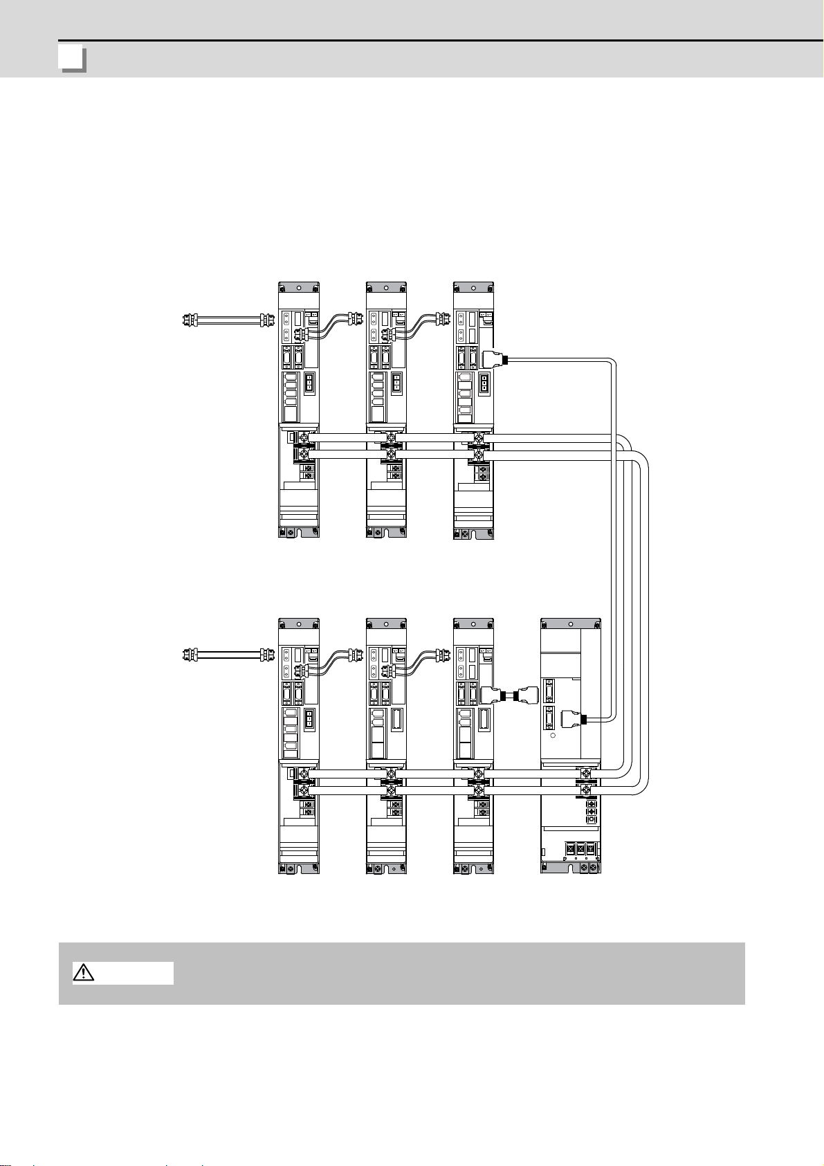
(2) When using two or more power supply units within a single NC communication bus system
Connected to the NC
MDS-D/DH-SP
8thaxis
(CV control axis)
MDS-D/DH-CV
[2]
MDS-D-SP2
6th/7th axis
MDS-D/DH-V2
1st/2nd axis
MDS-D/DH-V2
3rd/4th axis
(CV control axis)
MDS-D/DH-CV
[1]
MDS-D/DH-V1
5th axis
CAUTION
Two or more power supply units may be required within a single NC communication bus system if the spindle drive
unit capacity is large. The drive unit receiving power (L+, L-) from each power supply unit must always have NC
communication cable connection at the NC side of each power supply unit. In the NC communication bus
connection example below, power supply [1] cannot supply power (L+, L-) to the 5th axis servo drive unit.
For basic connection information, refer to the MDS-D/DH Series Instruction Manual.
Optical
communication
cable
CN4
CN4
Power
cannot be
supplied
CN4
CN4
Connections when using two or more power supply units within a single NC communication bus system
1. The drive unit receiving power (L+, L-) from each power supply unit must always have NC
communication bus connection at the NC side of each power supply unit.
2. If two or more power supply units are connected in the drive system, confirm that the units
are not connected with each other through the L+ and L- lines before turning ON the power.
Also make sure that the total capacity of the drive units connected to the same power
supply unit meets the unit's selected capacity.
8
Page 26

M700VS Series Setup Manual
2.1 Connecting and Setting the Drive Unit
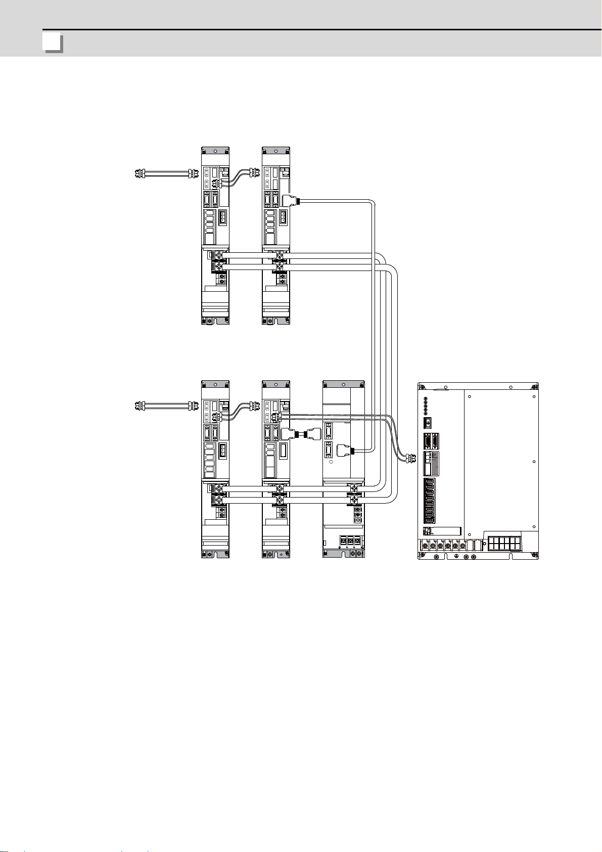
(3) When using one power supply shared unit by two NC communication bus systems
(
MDS-D/DH-V2
1st/2nd axis
MDS- D/DH -V2
3rd/4th axis
(
)
CAUTION
In systems employing a number of small-capacity drive units, a single power supply unit can be shared by two NC
communication bus systems. In this case, a power supply control axis must be set for each axis of each NC
communication bus.
For basic connection information, refer to the MDS-D/DH Series Instruction Manual.
Connected to the NC
(1st part system)
Optical
communication
cable
Connected to the NC
2nd part system
MDS-D/DH-V2
8th/9th axis
MDS-D/DH-V1
10th axis
MDS-D/DH-V2
5th/6th axis
MDS-D-SP2
11th/12th axis
MDS-D/DH-V1
7th axis
(CV control axis)
CN4
MDS-D/DH-SP
13th axis
CV control axis)
MDS-D/DH-CV
(Shared)
Optical
communication
cable
CN4
CN4
CN9
Connections when using one power supply shared by two NC communication bus systems
If the two NC communication bus systems include a spindle drive unit, connect the power
supply unit's CN4 connector to the CN4 connector of the largest capacity spindle drive unit. If
there is no spindle drive unit, connect to the unbalance-axis servo drive unit.
9
Page 27

2 Connecting and Setting the Hardware
MITSUBISHI CNC
2.1.1.2 Connecting with MDS-DM Series
CAUTION
POINT
Connect the NC and the drive units by the optical communication cables. The distance
between the NC and the final drive unit must be within 30m and the bending radius within
80mm.
Axis Nos. are determined by the rotary switch for setting the axis No. (Refer to the MDS-DM
Series Instruction Manual.) The axis No. has no relation to the order for connecting to the NC.
(1) Connecting the MDS-DM-V3
(a) When using one power supply unit
Connect the largest-capacity spindle drive unit to the final axis of the NC communication bus in order to control
the power supply unit. The spindle drive unit must be installed adjacent to the power supply unit. In the system
with servo only, a servo drive uni t for controlling unbalance axis must be installed in the same manner in the
same way.
< Connection >
CN1A : CN1B connector on NC or previous stage's drive unit
CN1B : CN1A connector on next stage's drive unit
CN4 : Connector for communication between power supply unit (master side) and drive unit
Connected
to the NC
Optical
communication
cable
MDS-D-V2
1st/2nd axis
MDS-DM-V3
3rd/4th/5th axis
MDS-D-SP
6th axis
(Final axis)
CN4
CN4
MDS-D-CV
The optical communication cables from the NC to the
final drive unit must be within 30m.
Connection when using one power supply unit
10
Page 28

M700VS Series Setup Manual
2.1 Connecting and Setting the Drive Unit
(b) When using two or more power supply units within a single NC communication bus system
[2][1]
MDS-DM-V3
MDS-D-V2
MDS-D-CV MDS-D-V1 MDS-D-SP
MDS-D-CV
7th axis
(CV control axis)
6th axis
1st/2nd axis
(CV control axis)
3rd/4th/5th axis
CAUTION
Two or more power supply units may be required within a single NC communication bus system if the spindle
drive unit capacity is large. The drive unit receiving power (L+, L-) from each power supply unit must always
have NC communication cable connection at the NC side of each power supply unit. In the NC communication
bus connection example below, power supply [1] cannot supply power (L+, L-) to the 6th axis servo drive unit.
For basic connection information, refer to the MDS-DM Series Instruction Manual.
Connected to the NC
Optical
communication
cable
CN4
CN4
Power
cannot be
supplied
CN4
CN4
Connections when using two power supply units within a single NC communication bus system
1. The drive unit receiving power (L+, L-) from each power supply unit must always have NC
communication bus connection at the NC side of each power supply unit.
2. If two or more power supply units are connected in the drive system, confirm that the units
are not connected with each other through the L+ and L- lines before turning ON the power.
Also make sure that the total capacity of the drive units connected to the same power
supply unit meets the unit's selected capacity.
11
Page 29
2 Connecting and Setting the Hardware
MITSUBISHI CNC
(c) When using one power supply shared unit by two NC communication bus systems
(
)
CAUTION
In systems employing a number of small-capacity drive units, a single power supply unit can be shared by two
NC communication bus systems. In this case, a power supply control axis must be set for each axis of each
NC communication bus.
For basic connection information, refer to the MDS-DM Series Instruction Manual.
Connected to the NC
(1st part system)
Optical
communication
cable
Connected to the NC
2nd part system
MDS-D-V2 MDS-D-V2
1st/2nd axis th axis3rd/4
MDS-DM-V3
8th/9th/10th axis
MDS-D-SP
MDS-DM-V3
5th/6th/7th axis
(CV control axis)
MDS-D-SP MDS-D-CV
12th axis
(CV control axis)
CN4
(Shared)11th axis
Optical
communication
cable
CN4
CN4
CN9
Connections when using one power supply shared by two NC communication bus systems
If the two NC communication bus systems include a spindle drive unit, connect the power
supply unit's CN4 connector to the CN4 connector of the largest capacity spindle drive unit. If
there is no spindle drive unit, connect to the unbalance-axis servo drive unit.
12
Page 30

M700VS Series Setup Manual
2.1 Connecting and Setting the Drive Unit
(2) Connecting the MDS-DM-SPV Series
MDS-DM-SPV3F
Spindle:1st axis
Servo:2nd/3rd/4th axis
to the NC
Connected
communication
Optical
cable
MDS-D-V2
MDS-D-SP
MDS-DM-SPV3F
MDS-D-CV
5th/6th axis 7th axis
(Final axis)
Servo:2nd/3rd/4th axis
Spindle:1st axis
(a) When using only MDS-DM-SPV Series
(b) When using the MDS-D unit together
Connected
to the NC
Optical
communication
cable
The optical communication cables from the NC to the
final drive unit must be within 30m.
CN4
CN4
13
Page 31
2 Connecting and Setting the Hardware
MITSUBISHI CNC
(c) When using one power supply shared unit by two NC communication bus systems
(
)
Connected to the NC
(2nd part system)
Optical
communication
cable
Connected to the NC
1st part system
MDS-D-V2
9th/10th axis
MDS-DM-V3
5th/6th/7th axis
MDS-D-V2
11th/12th axis
(CV control axis)
8th axis
(CV control axis)
CN4
MDS-D-CVMDS-D-SP
(Shared)
MDS-DM-SPV3F
Spindle:1st axis
Servo:2nd/3rd/4th axis
Optical
communication
cable
CN4
CN4
CN9
14
Page 32

M700VS Series Setup Manual
2.1 Connecting and Setting the Drive Unit
2.1.1.3 Connecting with MDS-SVJ3/SPJ3 Series
CAUTION
POINT
Connected
to the NC
Optical
communication
cable
MDS-D-SVJ3
1st axis
MDS-D-SVJ3
2nd axis
MDS-D-SVJ3
3rd axis
MDS-D-SPJ3
4th axis
The optical communication cable up to 5m can be used in G396 series, and up to 20m in G380 series.
Connect the NC and the drive units by the optical communication cables. The bending radius
must be within 50mm.
Axis Nos. are determined by the rotary switch for setting the axis No. (Refer to the MDS-SVJ3/
<Connection>
CN1A: CN1B connector on NC or previous stage's drive unit
CN1B: CN1A connector on next stage's drive unit
SPJ3 Series Instruction Manual.) The axis No. has no relation to the order for connecting to
the NC.
2.1.2 Setting up without Connecting to the Motor/ Drive unit
When connecting the motor or drive unit after setting up the system, set the axis data beforehand to enable the operation
without the motor or drive unit. The following shows the procedures.
Setting up without Connecting to the Motor
The axis detach function can be used for servo axis. The detach function cannot be used for spindle.
(1) Set the drive unit rotary switch and "#1021 mcp_no" for the axis that is not connected to the motor.
(2) Set "1" to the parameter "#1070 axoff" for the axis that is not connected to the motor.
(3) Do (a) or (b).
(a) Set "1" to parameter "#8201 AX. RELEASE" for the axis that is not connected to the motor.
(b) Turn ON the control axis detach signal (Y780) for the axis that is not connected to the motor.
Setting up without Connecting to the Drive unit
Set the following parameters.
(1) Set "#1021 mcp_no" (for the servo axis) or "#3031 smcp_no" (for the spindle axis) to the axis that is not connected
to the drive unit.
(2) Set the following parameters to the axis that is not connected to the drive unit.
For the servo axis: Set "1" to "#2018 no_srv".
For the spindle axis: Set "0" to "#3024 sout".
After connecting to the drive unit, make sure to set "#2018 no_srv" to "0" and "#3024 sout" to "1".
15
Page 33

2 Connecting and Setting the Hardware
MITSUBISHI CNC
2.2 Setting the Rotary and DIP Switches
L axis
M axis
1-axis
spindle drive unit
(MDS-D/DH-SP)
2-axis
spindle drive unit
(MDS-D-SP2)
2.2.1 MDS-D/DH Series
(1) Setting the rotary switch
Set the axis number with the rotary switch.
1-axis
Servo drive unit
(MDS-D/DH -V1)
2-axis
Servo drive unit
(MDS-D/DH -V2)
#
$
%
&
'
(
#
$
%
&
'
(
MDS-D/DH-V1/V2/SP/SP2 setting
Rotary switch setting Axis No.
Power supply un it
(MDS-D/DH -CV)
#
$
%
&
'
(
$
%
&
'
(
#
$
%
&
'
(
#
$
%
&
'
(
#
01st axis
1 2nd axis
23rd axis
3 4th axis
4 5th axis
5 6th axis
6 7th axis
7 8th axis
8 9th axis
9 10th axis
A 11th axis
B 12th axis
C 13th axis
D 14th axis
E 15th axis
F 16th axis
$
%
&
#
'
(
MDS-D/DH-CV setting
When not using the external emergency stop: Set SW1 to "0"
When using the external emergency stop: Set SW1 to "4"
*Any other settings are prohibited.
16
Page 34

M700VS Series Setup Manual
2.2 Setting the Rotary and DIP Switches
(2) Setting the DIP switch
(A) (B)
As a standard setting, turn the all DIP switches OFF.
The switches are OFF when facing bottom as illustrated.
Turning these switches ON sets the corresponding axis to the unused axis.
Carry out the unused axis setting when you use the multi-axes drive unit that has any unused axis.
(A) Used to set L axis to an unused axis
(B) Used to set M axis to an unused axis
17
Page 35

2 Connecting and Setting the Hardware
MITSUBISHI CNC
2.2.2 MDS-DM Series
<MDS-DM-V3 Series>
(1) Rotary switch settings
Before turning on the power, the axis No. must be set with the rotary switch. The rotary switch settings will be
validated when the drive un i t s are tu rned ON.
3-axis
Servo drive unit
(MDS-DM-V3)
L axis
8
79
6A
5B
4C
3D
2E
1F
0
M axis
8
79
6A
5B
4C
3D
2E
1F
0
Spindle drive unit
S axis
8
79
6A
5B
4C
3D
2E
1F
0
(MDS-D-SP
8
79
6A
5B
4C
3D
2E
1F
0
Rotary switch setting Axis No.
01st axis
1 2nd axis
23rd axis
3 4th axis
4 5th axis
5 6th axis
6 7th axis
7 8th axis
8 9th axis
9 10th axis
A 11th axis
B 12th axis
C 13th axis
D 14th axis
E 15th axis
F 16th axis
18
Page 36

M700VS Series Setup Manual
2.2 Setting the Rotary and DIP Switches
(2) Setting the DIP switch
(A)(B) (C)
As a standard setting, turn the all DIP switches OFF.
The switches are OFF when facing bottom as illustrated.
Turning these switches ON sets the corresponding axis to the unused axis.
Carry out the unused axis setting when you use the multi-axes drive unit that has any unused axis.
(A) Used to set L axis to an unused axis
(B) Used to set M axis to an unused axis
(C) Used to set S axis to an unused axis.
<MDS-DM-SPV2/SPV3 Series>
The setting of the axis number is fixed as follows in the MDS-DM-SPV2/SPV3 Series.
Setting the MDS-DM-SPVx Details
1st axis Spindle axis
2nd axis L-axis
3rd axis M-axis
4th axis S-axis (Only MDS-DM-SPV3)
When using the MDS-DM-SPV2/SPV3, MDS-D and MDS-DM-V3 together, the axis numbers for the MDS-DMSPV2/SPV3 are fixed as above. Set the axis numbers from 4th axis or 5th axis.
19
Page 37

2 Connecting and Setting the Hardware
MITSUBISHI CNC
2.2.3 MDS-D-SVJ3/SPJ3 Series
Set the axis number with the rotary switch.
MDS-D-SVJ3 MDS-D-SPJ3
8
79
6A
5B
4C
3D
2E
1F
0
Rotary switch setting Axis No.
01st axis
1 2nd axis
23rd axis
3 4th axis
4 5th axis
5 6th axis
6 7th axis
7 8th axis
8 9th axis
9 10th axis
A 11th axis
B 12th axis
C 13th axis
D 14th axis
E 15th axis
F 16th axis
5B
4C
3D
8
79
6A
2E
1F
0
20
Page 38

M700VS Series Setup Manual
2.3 Connecting the Batteries
2.3 Connecting the Batteries
BAT
Battery
Battery cover
Battery holder
connector
CAUTION
2.3.1 Control Unit Battery
The battery is not connected when the machine is delivered. Be sure to connect the battery before
starting up.
A lithium battery in the control unit battery holder retains parameter settings, machining programs and the like, which
requires to be backed up at the power OFF.
Battery Q6BAT
Battery cumulative data holding time
Battery life Approx. 5 years (from date of battery manufacture)
[Installation method]
(1) Check that the machine power is turned OFF. (If the power is not OFF, turn it OFF.)
(2) Confirm that the control unit LED, 7-segment display, etc., are all OFF.
(3) Open the battery cover of the control unit. Pull the right side of the battery cover toward front.
(4) Fit the new battery into the battery holder.
(5) Insert the connector connected to the new battery into the BAT connector. Pay attention to the connector
orientation: do not insert backwards.
(6) Close the front cover of the control unit. At this time, confirm that the cover is closed by listening for the "click"
sound when the latch catches.
45,000 hours (At 0 to 45°C. The life will be shorter if the temperature is high.)
[Precautions for handling battery]
(1) Do not disassemble the battery.
(2) Do not place the battery in flames or water.
(3) Do not pressurize and deform the battery.
(4) This is a primary battery so do not charge it.
Do not short-circuit, charge, overheat, incinerate or disassemble the battery.
21
Page 39

2 Connecting and Setting the Hardware
MITSUBISHI CNC
2.3.2 Servo Drive Unit Battery
BT1
Battery
To battery holder
Battery connector
Battery connector connection part magnified figure
Connector for
connecting cell battery
Connect the cell battery with BT1.
MDS-BTCASE
Battery
Dedicated case
(Note) The battery connection is not necessary unless the drive unit employs absolute position detection. (Spindle
drive unit does not require the battery, because the unit does not employ absolute position detection.)
MDS-D/DH-V1/V2 and MDS-DM-V3
Connect the battery connector to the connector of the drive unit.
BTA
1 2 1
1 2
BTB
(Note) There are different types of battery. Refer to the drive unit's specification manual for details.
Type ER6V-C119B A6BAT(MR-BAT)
Installation typeDrive unit with battery holder type Dedicated case type
Hazard class Not applicable
Number of
connectable
Up to 2 axes
axes
Not applicable
(24 or less)
Up to 8 axes
(When using dedicated
case)
MDS-A-BT- □□
Unit and battery integration
type
Class9
(excluding MDS-A-BT-2)
2 to 8 axes Up to 8 axes
Battery change Possible Possible Not possible Possible
(2)
Appearance
(1)
To the battery
holder
Battery connector
バッテリ
Battery
ER6V-C119B
A6BAT
(MR-BAT)
(3)
MDS-BTBOX-36
Unit and battery integration
type
Not applicable
(4)
22
Page 40

M700VS Series Setup Manual
2.3 Connecting the Batteries
MDS-DM-SPV2/SPV3
BT1
Battery
To battery holder
Battery
connector
Battery connector connection part magnified figure
Connector for
connecting cell battery
Connect the cell battery with BT1.
Connect the battery connector to the connector of the drive unit.
12
12
BTA
MDS-D-SVJ3
Connect the battery connector to the connector BAT of the drive unit.
BAT
Remove
Install
23
Page 41

2 Connecting and Setting the Hardware
MITSUBISHI CNC
2.4 Connecting and Setting the Remote I/O Unit
(A)
(B)
(C)
(D)
DX10* DX11*/12* DX14*
A
2.4.1 Outline of the Remote I/O Unit
There are eight types of remote I/O unit (FCUA-DX***): DX10*, DX11*, DX12* and DX14* (* is "0" or "1"). Specifications
are different as shown below. Each unit has one or two rotary switch(es) for unit No. setting, which links the device Nos.
(with X/Y).
Front
(H)
(A)
(E)
(A)
(B)
(C)
(D)
(A) Left input connector
(B) DIO specification switch
Currently not used. Always set to "OFF".
Front view View from A direction
OFF
(C),(F) Rotary switch
(D) Left output connector
(E) Right input connector
(G) Right output connector
(H) Analog input/output connector
(F)
(G)
(B)
(C)
(D)
(F)
24
Page 42

M700VS Series Setup Manual
2.4 Connecting and Setting the Remote I/O Unit
Bottom
(A)
(B)
(C)
(A) RIO1 (From controller)
(B) RIO2 (To terminating resister or to next RIO unit)
(C) DCIN (24VDC input)
Unit type
DX10* (FCUA-DX10*)
Machine control signals that can be
handled
Digital input signal (DI) (Photocoupler
insulation)
Left Right Total
32 points - 32 points
Digital output signal (DO) (Non-insulated) 32 points - 32 points
DX11* (FCUA-DX11*)
Digital input signal (DI) (Photocoupler
insulation)
32 points 32 points 64 points
Digital output signal (DO) (Non-insulated) 32 points 16 points 48 points
DX12* (FCUA-DX12*)
Digital input signal (DI) (Photocoupler
insulation)
Digital output signal (DO) (Non-insulated) 32 points 16 points 48 points
32 points 32 points 64 points
Analog output (AO) - 1 point 1 point
DX14* (FCUA-DX14*)
Digital input signal (DI) (Photocoupler
insulation)
Digital output signal (DO) (Non-insulated) 32 points - 32 points
32 points - 32 points
Analog input (AI) - 4 points 4 points
Analog output (AO) - 1 point 1 point
(Note) "*" in the table is "0" when the output is sink type, and is "1" when the output is source type. The input is
changeable.
Number of
occupied
stations
1
2
2
2
25
Page 43

2 Connecting and Setting the Hardware
MITSUBISHI CNC
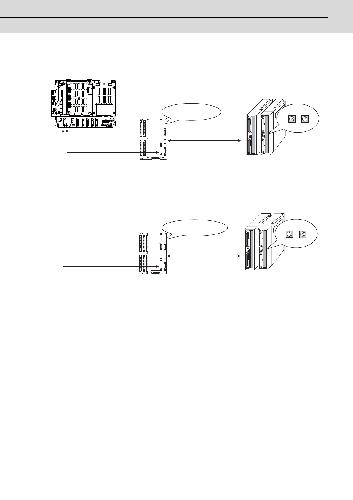
2.4.2 Connection and Station No. Setting on Remote I/O Unit
㨪
㨪
RIO1
CG72
G214
FCUA-R211/SH41
FCU7-MU531/ FCU7-MU541/ FCU7-MA541
FCUA-DX1**
FCUA-DX1**
Station No.1 - 8
Remote I/O unit
Control unit
Station No.1 - 8
Remote I/O 2ch
Max. 8 channels
Max. input: 256 points (X000 to X0FF)
Max. output: 256 points (Y000 to Y0FF)
Max. 8 channels
Max. input: 256 points (X100 to X1FF)
Max. output: 256 points (Y100 to Y1FF)
Remote I/O 1ch
When connecting directly to the control unit
(Note) A remote I/O unit has one or two rotary switch(es) for unit No. setting, which links the device Nos. (with X/
Y). The rotary switch setting is as follows, from "0" to "7".
When using MITSUBISHI CNC Machine operation panel, RIO station No. "4" to "6" will be occupied.
Station
No.
Rotary switch
10
21
32
43
54
65
76
87
26
Page 44
M700VS Series Setup Manual
2.4 Connecting and Setting the Remote I/O Unit
When connecting to the operation panel I/O unit
㨪
㨪
FCU7-DX710/711
FCUA-R211
FCUA-R211
RIO3
RIO3
FCU7-DX720/721
/730/731
G011
G011
CG71
Control unit
Operation panel I/O unit
Remote I/O 3ch
Max. 4 channels
Max. input: 128 points (X240 to X2BF)
Max. output: 128 points (Y240 to Y2BF)
Max. 3 channels
Max. input: 96 points (X260 to X2BF)
Max. output: 96 points (Y260 to Y2BF)
Remote I/O unit
Station No.3 - 6
Remote I/O 3ch
Max. input: 96 points (X200 to X25F)
Max. output: 96 points (Y200 to Y25F)
Max. input: 64 points (X200 to X23F)
Max. output: 64 points (Y200 to Y23F)
Station No.4 - 6
Occupies
the station No. 1, 2, 7, 8
Occupies
the station No. 1, 2, 3, 7, 8
FCUA-DX1**
FCU7-MU531/ FCU7-MU541/ FCU7-MA541
(Note) Operation panel I/O unit occupies the specified Nos. of stations. (Station No. 7 and 8 are reserved for
manual pulse generator.)
RIO3 can use either four stations (3rd to 6th) or three stations (4th to 6th) which depends on the
operation panel I/O unit type.
27
Page 45

2 Connecting and Setting the Hardware
MITSUBISHI CNC
2.4.3 Station No. Setting when Using Multiple Remote I/O Units
0
㧗
FCUA-DX100/101
0
1
2
㧗
㧗
FCUA-DX100/101
FCUA-DX110/111
or
FCUA-DX120/121
Multiple remote I/O units can be used, as long as the total No. of occupied stations connected with serial links is
eight or less. (three/four or less when connected to the operation panel I/O unit).
Unit type Number of occupied stations
FCUA-DX10* 1
FCUA-DX11* 2
FCUA-DX12* 2
FCUA-DX14* 2
When using multiple remote I/O units, a characteristic station No. must be set for each unit. The FCUA-DX10* unit
has one rotary switch, FCUA-DX11*, DX12* and DX14* unit have two. Each of these switches must be set to a
characteristic station No. within a range of 0 to 7 (2 or 3 to 5 when connected to the operation panel I/O unit).
When connecting directly to the control unit
Setting example 1
Total number of occupied stations: 1
Setting example 2
Number of occupied stations: 1 2
Total number of occupied stations: 3
28
Page 46

M700VS Series Setup Manual
2.4 Connecting and Setting the Remote I/O Unit
Setting example 3
0 1
㧗 㧗 㧗
㧗
2 3
4 5
6 7
FCUA-DX110/111
or
FCUA-DX120/121
Number of occupied stations: 2 2 2 2
Total number of occupied stations: 8 (Maximum configuration)
29
Page 47

2 Connecting and Setting the Hardware
MITSUBISHI CNC
When connecting to the operation panel I/O unit
㧗
2
FCU7-DX710/711
FCUA-DX100/101
+
4
5
+
2
3
FCU7-DX710/711
FCUA-DX110/111
or
FCUA-DX120/121
FCUA-DX110/111
or
FCUA-DX120/121
Station No. 1, 2, 7, 8 (or 1, 2, 3, 7, 8) are occupied by the operation panel I/O unit. (Station No. 7 and 8 are reserved
for manual pulse generator.)
The maximum numbers of stations and I/O points assigned to remote I/O unit(s) via RIO3 are as follows.
Operation panel I/O unit
type
FCU7-DX710 4 stations (No. 3 to 6) 128 points/128 points 2 to 5
FCU7-DX711 4 stations (No. 3 to 6) 128 points/128 points 2 to 5
FCU7-DX720/730 3 stations (No. 4 to 6) 96 points/96 points 3 to 5
FCU7-DX721/731 3 stations (No. 4 to 6) 96 points/96 points 3 to 5
Setting example 1
Max. number of stations
(RIO3 connection)
Max. number of I/O
points (RIO3
connection)
Rotary switch
Setting range
Remote I/O
Number of occupied stations: 1
Total number of occupied stations: 1
Setting example 2
Number of occupied stations: 2 2
Total number of occupied stations: 4 (Maximum configuration)
30
Page 48

M700VS Series Setup Manual
2.4 Connecting and Setting the Remote I/O Unit
Setting example 3
+
3
+
4
5
FCU7-DX720/721
/730/731
FCUA-DX100/101
FCUA-DX110/111
or
FCUA-DX120/121
Number of occupied stations: 1 2
Total number of occupied stations: 3 (Maximum configuration)
31
Page 49

2 Connecting and Setting the Hardware
MITSUBISHI CNC
2.4.4 Device No. Assignment
The devices used by the PLC are determined as follows after the station Nos. are set with the rotary switches.
Rotary switch No.
0 X00 to X1F Y00 to Y1F(Y0F)
1 X20 to X3F Y20 to Y3F(Y2F)
2 X40 to X5F Y40 to Y5F(Y4F)
3 X60 to X7F Y60 to Y7F(Y6F)
4 X80 to X9F Y80 to Y9F(Y8F)
5 XA0 to XBF YA0 to YBF(YAF)
6 XC0 to XDF YC0 to YDF(YCF)
7 XE0 to XFF YE0 to YFF(YEF)
Rotary switch No.
0 X100 to X11F Y100 to Y11F(Y10F)
1 X120 to X13F Y120 to Y13F(Y12F)
2 X140 to X15F Y140 to Y15F(Y14F)
3 X160 to X17F Y160 to Y17F(Y16F)
4 X180 to X19F Y180 to Y19F(Y18F)
5 X1A0 to X1BF Y1A0 to Y1BF(Y1AF)
6 X1C0 to X1DF Y1C0 to Y1DF(Y1CF)
7 X1E0 to X1FF Y1E0 to Y1FF(Y1EF)
Device No. read in Output device No. Analog output (AO)
RIO channel 1 RIO channel 1 RIO channel 1
The rotary switches
correspond to the file
registers R200 to R207 in
order of small numbers.
Device No. read in Output device No. Analog output (AO)
RIO channel 2 RIO channel 2 RIO channel 2
Not possible (Neither input
nor output is possible)
Rotary switch No.
0-1-2 X240 to X25F Y240 to Y25F(Y24F)
3 X260 to X27F Y260 to Y27F(Y26F)
4 X280 to X29F Y280 to Y29F(Y28F)
5 X2A0 to X2BF Y2A0 to Y2BF(Y2AF)
6-7--
The values shown in parentheses are the device range of the card mounted to the right side of the unit.
Device No. read in Output device No. Analog output (AO)
RIO channel 3 RIO channel 3 RIO channel 3
Not possible (Neither input
nor output is possible)
32
Page 50

M700VS Series Setup Manual
2.4 Connecting and Setting the Remote I/O Unit
(Note) When the analog output is equipped to several RIO channels, maximum of four RIO channels will be valid in the
RIO1
RIO3
AO
AO
AO
Controlunit
RIO unit
OperationpanelI/Ounit
Second
station
Fourth
station
Sixth station
following order of priority.
(1) RIO channel 1, (2) RIO channel 2, (3) RIO channel 3
(Ex.) When the analog output is equipped to RIO channel 1 and RIO channel 3.
#3024 sout R register Allocation of AO
2 R200 (AO1) 2nd station of RIO 1
3 R201 (AO2) 4th station of RIO 1
4 R202 (AO3) 6th station of RIO 3
5 R203 (AO4) -
The analog output R registers are allocated in ascending orde r of channels and station
CAUTION
numbers automatically. Therefore, the analog output destination may ch a nge de pe nding on
the added option.
33
Page 51

2 Connecting and Setting the Hardware
MITSUBISHI CNC
2.5 Initializing the NC Internal Data (SRAM)
A
A
A
A
The initialization does not affect the settings of the option parameters.
(1) With the NC power OFF, turn the left rotary switch (RSW1) to "0" and the right rotary switch (RSW2) to "C". Then,
turn the power ON.
NCLD1
0
1
F
D
B
7 9
8
NCLD2
0
1
F
2 E
D
3
4 C
B
5
6
2 E
3
4 C
5
6
7 9
8
RSW2 RSW1
(2) The LED display will change to "08." -> "00" -> "01" -> ... "08". The process is completed when "0Y" is displayed.
NCLD2NCLD1
(3) Turn the NC power OFF.
(4) Set the right rotary switch (RSW2) to "0".
(5) Turn the power ON again.
NCLD1
0
1
F
D
B
7 9
8
NCLD2
0
1
F
2 E
D
3
4 C
B
5
6
2 E
3
4 C
5
6
7 9
8
RSW2 RSW1
(Note) The initial screen after the initialization is displayed in English. Refer to "Setting on the System Setup Screen"
for how to set a language to display.
34
Page 52

35
3
Setting Up with M70/M700 SETUP
INSTALLER
Page 53

3 Setting Up with M70/M700 SETUP INSTALLER
MITSUBISHI CNC
(Note) M70/M700 SET UP INST ALLER is used to install language data other than Japanese and English, as well as
custom screens.
If you do not need the installation, go to the next section.
You can install the following data with M70/M700 SETUP INSTALLER.
(1) Language data
(2) Custom data
- Custom screen
- PLC alarm guidance
(3) Custom startup screen
A CF card is used for the installation.
The following products' operations have been guarante ed by MITSUBISHI.
<SanDisk CompactFlash cards>
64MB SDCFB-64-J60 (JAN: 4523052000294)
128MB SDCFB-128-J60 (JAN: 4523052000300)
256MB SDCFB-256-J60 (JAN: 4523052000317)
512MB SDCFB-512-J60 (JAN: 4523052000324)
1.0GB SDCFB-1024-J60 (JAN: 4523052000331)
<Panasonic SD memory cards>
1.0GB SD-CF adapter BN-CSDABP3/P + SD memory card (1GB) RP-SDM01GJ1A
2.0GB SD-CF adapter BN-CSDABP3/P + SD memory card (2GB) RP-SDM02GJ1A
(Note) The adapter BN-CSDABP3/P does not support SDHC memory card.
SD-CF adapter which supports SDHC is required when SDHC memory card is used.
The successful operations of these cards are confirmed under certain conditions. Some cards might not work under
the end-users' system environment. And some cards might have the same type name but different parts inside:
Complete guarantees cannot be given.
Contact the manufacturer or distribu to r be fo re pu rchase: There might be some cards which are not currently
produced.
36
Page 54

M700VS Series Setup Manual
3.1 Compatible Data and Folder Configuration in the CF Card
3.1 Compatible Data and Folder Configuration in the CF Card
(1) M70/M700 SETUP INSTALLER compatible data
Type Data Details Remarks
lang0_xxx.bin Language data (for FROM) Language
identification string is
Language data
Custom data
Custom startup
screen
lang1_xxx.bin
Custom screen
module
config.ini
customdef.ini
customload.txt
PLC alarm guidance
data
startupscreen.bmp
Language data (for expansion
FROM)
Interpreter data and object data
A setting file to register custom
screens
A setting file to register custom
screens on the menus and
function buttons located to the
default screen
A setting file to register a name
and a load order of the object data
HTML/JPEG files to be displayed
in the PLC alarm guidance
A bitmap file to be displayed on
the initial screen when the power
is turned ON
shown instead of xxx.
(ex. jpn: Japanese,
fra: French)
Color: 256 colors
(8 bit) Size:
640 * 440
37
Page 55

3 Setting Up with M70/M700 SETUP INSTALLER
MITSUBISHI CNC
(2) Folder configuration in the CF card
A
A
The following shows the folder configuration of the M70/M700 SETUP INSTALLER compatible data which is stored
in the CF card.
CF Card
Lang (language data folder)
0 (folder labeled by version)
lang0_jpn.bin (Japanese language data for FROM)
1 (folder labeled by version)
custom (custom data folder)
PLCAlarm (PLC alarm guidance folder)
PLCAlarm_0001_jpn.htm (PLC alarm guidance data)
Custom screen modules
Setting files
:
:
startupscreen.bmp (bitmap data for custom startup screen)
Installer (installer folder)
installer.o (installer)
38
Page 56

M700VS Series Setup Manual
3.2 Operation Procedure
3.2 Operation Procedure
3.2.1 Starting Up M70/M700 SETUP INSTALLER
(1) Insert the M70/M700 SETUP INSTALLER CF card into the card interface on front of display unit.
(2) Turn the power ON while pressing the cancel key .
The M70 SETUP INSTALLER Mode Select screen will appear in ab out 15 seconds after the startup screen
appears.
(Note1) Keep pressin g the cancel key until the Mode Select screen appears.
(Note2) Use the latest version of M70/M700 SETUP INSTALLER.
3.2.2 Installing Language Data
(1) Select [Lang Pack] on the Mode Select screen to switch to the Language Pack Install screen.
The language selection menus are displayed. The language currently installed is shown in the "Installed language"
field.
(Note) Pressi ng the menu changeover key (Next menu>>) displays the next language selection menus.
39
Page 57

3 Setting Up with M70/M700 SETUP INSTALLER
MITSUBISHI CNC
(2) Select the language to install with the menu key.
The language selected is shown in the "Now Selected Language" field.
(Note 1) To change the selected language, press [Clear] before selecting again.
(Note 2) The 2nd language can be selected when the expansion FROM is provided. (Cursor moves to the "2nd"
field after the 1st language has been selected.)
(3) Select [Install].
(4) A confirmation message appears. Select [Yes] to start the installation .
(5) A message appears when the installation has been completed.
(Note 1) Selecting [No] displays the language selection menus.
(Note 2) The language data installation takes about 105 seconds. Do not turn the power OFF during the
installation.
(6) To close M70/M700 SETUP INSTALLER, turn the power OFF and ON.
To return to the Mode Select screen, press the cancel key (<< Cancel).
40
Page 58

M700VS Series Setup Manual
3.2 Operation Procedure
3.2.3 Installing Custom Data
(1) Select [Custom Data] on the Mode Select screen to switch to the Custom Data Install screen.
(2) Select [Install].
(3) A confirmation message appears. Select [Yes] to start the installation.
(4) A message appears when the installation has been completed.
(Note 1) Selecting [No] displays the previous menus.
(Note 2) Do not turn the power OFF during the installation.
(5) To close M70/M700 SETUP INSTALLER, turn the power OFF and ON.
To return to the Mode Select screen, press the cancel key (<< Cancel).
41
Page 59

3 Setting Up with M70/M700 SETUP INSTALLER
MITSUBISHI CNC
3.2.4 Uninstalling Custom Data
(1) Select [Uninst] on the Custom Data Install screen.
(2) A confirmation message appears. Select [Yes] to start the uninstallati on.
(Note 1) Selecting [No] displays the previous menus.
(Note 2) Do not turn the power OFF during the uninstallation.
(3) A message appears when the uninstallation has been completed.
(4) To close M70/M700 SETUP INSTALLER, turn the power OFF and ON.
To return to the Mode Select screen, press the cancel key (<< Cancel).
42
Page 60

M700VS Series Setup Manual
3.2 Operation Procedure
3.2.5 Installing Custom Startup Screen
(1) Select [Custom StartUp] on the Mode Select screen to switch to the Custom Startup Screen Install screen.
(2) Select [Install].
(3) A confirmation message appears. Select [Yes] to start the installation.
(4) A message appears when the installation has been completed.
(Note 1) Selecting [No] displays the previous menus.
(Note 2) Do not turn the power OFF during the installation.
(5) To close M70/M700 SETUP INSTALLER, turn the power OFF and ON.
To return to the Mode Select screen, press the cancel key (<< Cancel).
43
Page 61

3 Setting Up with M70/M700 SETUP INSTALLER
MITSUBISHI CNC
3.2.6 Uninstalling Custom Startup Screen
(1) Select [Uninst] on the Custom Startup Screen Install screen.
(2) A confirmation message appears. Select [Yes] to start the uninstallati on.
(3) A message appears when the uninstallation has been completed.
(Note 1) Selecting [No] displays the previous menus.
(Note 2) Do not turn the power OFF during the uninstallation.
(4) To close M70/M700 SETUP INSTALLER, turn the power OFF and ON.
To return to the Mode Select screen, press the cancel key (<< Cancel).
44
Page 62

M700VS Series Setup Manual
3.3 List of Error Messages
3.3 List of Error Messages
Message Details
The 1st language is not selected.
The same language is selected.
The selected language does not exist.(1st)
The selected language does not exist.(2nd)
The custom data does not exist.
The file "startupscreen.bmp" does not exist.
The first language has not been selected at the installation of
language pack. Specify the first language again.
The same language has been selected as both first and second
language at the installation of language pack.
Specify the language again.
The language data, selected as the 1st language at the
installation of language pack, does not exist.
Ensure that the language data has been stored in the CF card,
and that version of the data is appropriate.
The language data, selected as the 2nd language at the
installation of language pack, does not exist.
Ensure that the language data has been stored in the CF card,
and that version of the data is appropriate.
The "custom" folder does not exist in the CF card.
Check the stored data in the CF card.
The "startupscreen.bmp" file does not exist in the CF card.
Check the stored data in the CF card.
45
Page 63

3 Setting Up with M70/M700 SETUP INSTALLER
MITSUBISHI CNC
46
Page 64

47
4
Setting the Parameters and Date/Time
Page 65

4 Setting the Parameters and Date/Time
MITSUBISHI CNC
Confirm the emergency stop state before carrying out the steps in this chapter.
WARNING
4.1 Selecting the NC System Type
When employing the lathe system, set the parameter as follows.
(1) On the Mainte screen, select [Mainte] and then [Psswd input].
Enter "MPARA" in the setting area and press the INPUT key.
(Note 1) To enter the character "A", press the shift key and then "A" key. Do not press both keys at the same time.
(Note 2) The entered password is displayed as "*****". See below.
(2) Press the cancel key to return to the Mainte screen. Then select [Param].
(3) Select [Param number]. Enter "1007" in the setting area and press the INPUT key.
The screen changes to the base system parameters screen. The cursor moves to the "#1007 System type select"
field.
(4) Enter "1" in the setting area and press the INPUT key. (0: Machining center system 1: Lathe system)
(5) Turn the power OFF and ON.
48
Page 66

M700VS Series Setup Manual
4.2 Setting on the System Setup Screen
4.2 Setting on the System Setup Screen
Set the following items on the system setup screen.
- Displayed language and the number of spindle connections
- Number of axes and command type for each part system
- Servo I/F connection channel and rotary switch setting for each spindle, as well as types of the motor and the
power supply connected to each spindle drive
- Servo I/F connection channel and rotary switch setting for each servo axis, as well as types of the motor,
encoder, and the power supply connected to each servo drive
(1) Enter the password on the Mainte screen.
(a) On the Mainte screen, select [Mainte] and then [Psswd input].
(b) Enter "MPARA" in the setting area and press the INPUT key.
(Note 1) To enter the character "A", press the shift key and then "A" key. Do not press both keys at the same time.
(2) Select a displayed language.
(a) Press the cancel key to return to the Mainte screen. Select [Mainte] and then [System Setup].
(b) Set the No. of the language to display in "language displayed".
49
Page 67

4 Setting the Parameters and Date/Time
MITSUBISHI CNC
(3) Carry out the spindle and servo axis settings. Set the following items.
Common setting
Number of spindles: Set the number of spindles connected to the NC. This setting is registered at "#1039
spinno (Number of spindles)".
Setting by system
Number of axes:
Set the number of axes for each part system and PLC. This setting is registered at "#1002
axisno (Number of axes)".
(Note) A setting error occurs if a value "1" or higher is set for any of the 2nd to 4th part
systems while the setting for the previous part system is "0".
Command type
Set the command type for each part system. This setting is registered at "#1037 cmdtyp
(Command type)".
(Note) Although this can be set individually for each part system, it will be shared by
the entire part system if specified for the machining center.
Setting by spindle area
Ch / Rotary SW No.
Set the servo I/F connection channel and the rotary switch No. (2-digit value) for each spindle
drive unit. This setting is registered at "#3031 smcp_no (Drive unit I/F channel No. (spindle))".
1st digit: Servo I/F connection channel
2nd digit: Rotary switch No.
Motor type:
Set the motor types that are connected to each spindle. Input the values as indicated at the
guidance display area. The input values are not converted to motor types.
Power Supply type:
Set the power supply types that are connected to each spindle drive unit.
Input the values as indicated at the guidance display area. The input values are then converted
to, and displayed as, power supply types. "0" means "No connection".
Setting by servo
Ch / Rotary SW No.
Set the servo I/F connection channel and the rotary switch No. (2-digit value) for each servo
drive unit. This setting is registered at "#1021 mcp_no (Drive unit I/F channel No. (servo))".
1st digit: Servo I/F connection channel
2nd digit: Rotary switch No.
Motor type:
Set the motor types that are connected to each servo axis.
Input the values as indicated at the guidance display area. The input values are then converted
to, and displayed as, motor types.
Detector type:
Set the encoder types that are connected to each servomotor.
Input the values as indicated at the guidance display area. The input values are then converted
to, and displayed as, encoder types.
Power Supply type:
Set the power supply types that are connected to each servo drive unit.
Input the values as indicated at the guidance display area. The input values are then converted
to, and displayed as, power supply types. "0" means "No connection".
50
Page 68

M700VS Series Setup Manual
4.2 Setting on the System Setup Screen
Setting example (with three servo axes and a spindle)
X axis
Power supply unit
Y axis
Z axis
S
p
indle
51
Page 69

4 Setting the Parameters and Date/Time
MITSUBISHI CNC
(5) Write the parameter settings and format the system.
(a) Select [Param setting].
(b) The message "Set up parameter? (Y/N)" appears. Press "Y".
(c) The message "Param set ended. Format NC memory? (Y/N)" appears. Press "Y".
(d) The message "Format complete" appears when the format is completed.
(6) Turn the power OFF and ON.
(Note) When MDS-D-SVJ3/SPJ3 Series is used, the regenerative resistor type must be set with the servo parameter
"#2236 SV036" and the spindle parameter "#13032 SP032" in addition to the settings above.
52
Page 70

M700VS Series Setup Manual
4.3 Setting the Parameters for the Machine Specifications
4.3 Setting the Parameters for the Machine Specifications
(1) On the Mainte screen, select [Mainte] and then [Psswd input]. Enter "MPARA" in the setting area and press the
INPUT key.
(Note 1) To enter the character "A", press the shift key and then "A" key. Do not press both keys at the same time.
(2) Press the cancel key to return to the Mainte screen. Then select [Param].
Set the parameters according to the machine specifications . Setting of the following parameters is necessary.
Base system parameters
"#1025 I_plane (Initial plane selection)"
"#1026 base_I (Base axis I)"
"#1027 base_J (Base axis J)"
"#1028 base_K (Base axis K)"
"#1029 aux_I (Flat axis I)"
"#1030 aux_J (Flat axisJ)"
"#1031 aux_K (Flat axis K)"
Base axis specification parameter
"#1013 axname (Axis name)"
Base common parameters
"#1038 plcsel (Ladder selection ... Set "0")"
"#1041 I_inch (Initial state (inch))"
"#1042 pcinch (PLC axis command (inch))"
"#1239 set11/bit1 (Handle I/F selection)"
"#1240 set12/bit0 (Handle input pulse)"
Axis specification parameter
"#2001 rapid (Rapid traverse rate)"
"#2002 clamp (Cutting feedrate for clamp function)"
"#2003 smgst (Acceleration and deceleration modes)"
"#2004 G0tL (G0 time constant)"
"#2007 G0tL (G1 time constant)"
Servo parameter
"#2201 SV001 (PC1 Motor side gear ratio)"
"#2202 SV002 (PC2 Machine side gear ratio)"
"#2218 SV018 (PIT Ball screw pitch)"
Spindle specification param ete r
"#3001 slimt1 (Limit rotation speed (Gear: 00))"
"#3002 slimt2 (Limit rotation speed (Gear: 01))"
"#3003 slimt3 (Limit rotation speed (Gear: 10))"
"#3004 slimt4 (Limit rotation speed (Gear: 11))"
"#3005 smax1 (Maximum rotation speed (Gear: 00))"
"#3006 smax2 (Maximum rotation speed (Gear: 01))"
"#3007 smax3 (Maximum rotation speed (Gear: 10))"
"#3008 smax4 (Maximum rotation speed (Gear: 11))"
"#3023 smini (Minimum rotation speed)"
"#3109 zdetspd (Z phase detection speed)"
53
Page 71

4 Setting the Parameters and Date/Time
MITSUBISHI CNC
(Note 1) These parameters are not set on the system setup screen. Use the parameter screen to set them.
0
Spindle rotation speed (r/min)
(r/min)
(Note 2) Refer to the section of "Explanation of Parameters" for the details of the parameters.
You can also refer to the parameter guidance display.
(Note 3) Parameters "#3001 slimt1 (Limit rotation speed (Gear: 00))" to "#3004 slimt4 (Limit rotation speed (Gear:
11))" are set with the spindle rotation speed which can be attained at the spindle motor's maximum
rotation speed. This value is obtained by multiplying the gear ratio on the value of "#13026 SP026 TSP
(Maximum motor speed)". Parameters "#3005 smax1 (Maximum rotation speed (Gear: 00))" to "#3008
smax4 (Maximum rotation speed (Gear: 11))" are set when the rotation speed is to be limited according
to the machine specifications, such as the spindle gear specifications. Up to four value can be set for
gear changeover.
SP026
Spindle motor rotation speed
slimt1 smax2 smax(n) slimt2 slimt(n)
smax1
54
Page 72

M700VS Series Setup Manual
4.4 Setting Date and Time
4.4 Setting Date and Time
(1) Select [Time] on the Monitr screen.
(2) Select [Time setting] on the integrated time screen.
The time setting mode is entered. The cursor appears at the "#1 Date" position in the Run-out time display.
(3) Set the date and time to "#1 Date" and "#2 Time" respectively.
55
Page 73

4 Setting the Parameters and Date/Time
MITSUBISHI CNC
56
Page 74

57
5
PLC Program Writing
Page 75

5 PLC Program Writing
MITSUBISHI CNC
In this manual, PLC program writing is executed by connecting a personal computer, which has GX Developer installed,
to the control unit. You can also save the PLC program in a CF card and write the data to NC using the external file
operations on PLC onboard. (M700V Series allows using a USB memory.) Refer to the PLC programming Manual for
details.
5.1 Setting the Ethernet Communication
(1) Click "Start" on the personal computer. Right-click on "My network" and select "Property".
(2) Right-click on "Local Area Connection" in My network window, and select "Properties".
(3) Click "Internet Protocol(TCP/IP)" on the "General" tab, and then click "Properties".
(4) Take a note of the displayed IP address and subnet mask.
58
Page 76

M700VS Series Setup Manual
5.2 Connecting the Control Unit and a Personal Computer
(5) Set the following addresses.
IP address: 192.168.200.2
Subnet mask: 255.255.255.0
(6) Click "OK" and close all the windows.
5.2 Connecting the Control Unit and a Personal Computer
Connect a personal computer, which has GX Developer installed, to the control unit.
LAN
(Note 1) GX Developer Version8 is required.
(Note 2) Use a cross LAN cable for the communication.
(Note 3) Carry out the Ethernet communication setting (IP address and so on) on the personal computer before
connecting it to NC.
GX Developer
59
Page 77

5 PLC Program Writing
MITSUBISHI CNC
5.3 Setting the Communication with GX Developer
(1) Start GX Developer on the personal computer. Open a created project.
(2) Select [Transfer setup...] from the [Online] menu.
(3) On the "Transfer Setup" screen, click "Ethernet board" in the "PC side I/F" field and double-click "Ethernet module"
in the "PLC side I/F" field.
(4) Select "QJ71E71" for "PLC", input "192.168.200.1" for IP address, then click "OK".
60
Page 78

M700VS Series Setup Manual
5.3 Setting the Communication with GX Developer
(5) Click "Other station(Single network)" in the "Other station" field on the "Transfer Setup" screen.
(6) Click "Connection test" to execute the test.
After confirming the message "Successfully connected", click "OK".
Click "OK" and close the "Transfer Setup" screen.
61
Page 79

5 PLC Program Writing
MITSUBISHI CNC
5.4 Setting the Parameters on GX Developer
(1) Double-click on [Parameter] --> [PLC parameter] in the project list on GX Developer. The "QnA Parameter" dialog
box appears.
(2) On the "Device" tab, confirm the foll ow i ngs are set.
Inside relay M: 10K
Retentive timer ST: 64 (Do not attach "K")
Confirm the other parameter settings.
(Note) There are two methods of ladder programming; independent program method and multi-program
method, which makes differences in parameter settings. An incorrect parameter setting in the ladder
programming may cause a write error.
For details of the parameter settings, refer to the PLC Programming Manual.
62
Page 80

M700VS Series Setup Manual
5.4 Setting the Parameters on GX Developer
(3) Check the "Allow" check box in the "Remote reset" field on the "PLC system" tab. Click "End".
63
Page 81

5 PLC Program Writing
MITSUBISHI CNC
5.5 Writing a PLC Program with GX Developer
(1) Select [Write to PLC...] from the [Online] menu.
(2) Check all the check boxes in the "Write to PLC" dialog box, and then click "Execute".
(3) GX Developer starts the PLC program writing. Confirmation dialog boxes appear during the writing. Select "Yes" on
all of them.
(Note 1) After the writing, select "Verify with PLC..." from the "Online" menu to check any error.
(Note 2) Do not turn the NC power OFF after the writing. Keep the power ON until the program is written to ROM.
64
Page 82

M700VS Series Setup Manual
5.6 Writing a PLC Program to ROM with GX Developer
5.6 Writing a PLC Program to ROM with GX Developer
(1) Select [Remote operation...] from the [Online] menu.
(2) Select "STOP" from the pull-down menu in the "Operation" field in the "Remote operation" dialog box. Click
"Execute".
65
Page 83

5 PLC Program Writing
MITSUBISHI CNC
(3) Select [Remote operation] again. Select "PAUSE" from the pull-down menu in the "Operation" field and click
"Execute". (Executing "PAUSE" starts the writing to NC ROM.)
(4) The message "Completed." appears when the writing to ROM is completed.
(Note) The program has been written to ROM although the on-board screen still shows the message "ROM-
Write incomplete".
The message will disappear when the screen has been changed.
(Note) You can also save the PLC program in a CF card and write the data to NC using the external file operations on
PLC onboard. Refer to the PLC programming Manual for details.
66
Page 84

M700VS Series Setup Manual
5.7 Setting the PLC Parameters
5.7 Setting the PLC Parameters
Symbol
name
7 6 5 4 3 2 1 0
0
#6449
R7824 L
Control unit
thermal
al arm on
S etting an d
display unit
thermal
mgmt on
-
Counter C
retention
Integrated
timer ST
retention
PLC counter
program on
PLC timer
program on
1 0
1
#6450
R7824 H
-
External
alarm
message
display
Alarm/
operator
cha nge
Ful l screen
display of
message
-
Operator
message on R method F method
Alarm
message on
2
#6451
R7825 L
- -
Onboard
ed iting not
possible
Onboard
simple
operation mode
on
Onbo ard
on
3
#6452
R7825 H
-
Branch
destination
label chec k
valid
Serial handy
terminal
comm. on
- -
Extended PLC
instruction
mode valid
-
GX
Developer
serial
communication
on
Select [Bit select] on the Mainte screen and set the bit selection parameters from #6449 to #6452.
See the following table for details of the parameters.
(Note) Functions marked with ■ may not be available for some machine types.
67
Page 85

5 PLC Program Writing
MITSUBISHI CNC
68
Page 86

69
6
Confirming the Basic Operation
Page 87

6 Confirming the Basic Operation
MITSUBISHI CNC
6.1 Checking Inputs/Outputs and Alarms
(1) Checking the input signals
(a) Select [I/F dia] on the Diagn screen.
(b) Confirm that signals turn ON/OFF properly on the IF Diagnosis screen.
(2) Checking the alarm display
(a) Select [Alarm message] on the Diagn screen.
(b) Check any other alarm than "Emergency stop EXIN" displayed on the Alarm screen.
70
Page 88

M700VS Series Setup Manual
6.2 Confirming Manual Operation
6.2 Confirming Manual Operation
6.2.1 Using the Manual Pulse Generator
(1) Select the handle mode.
(2) Set the handle feed magnification to a minimum value.
(3) Cancel the emergency stop. Confirm the READY lamp is ON on the keyboard.
(Note) If any abnormal noise or vibration occurs, execute an emergency stop and take a measure against
vibration. (Refer to "First Measure Against Vibration".)
(4) Select an axis and turn the manual pulse generator by one scale. Confirm the direction and the amount of the
movement on the current position display.
If the display is not correct, check parameters, PLC programs and devices' connections.
(5) Turn the manual pulse generator and confirm the direction and the amount of the machine's movement.
If the display is not correct, check parameters.
(Related parameters: "#1018 ccw (Motor CCW)", "#2201 PC1 (Motor side gear ratio)", "#2202 PC2 (Machine side
gear ratio)", "#2218 PIT (Ball screw pitch)" and so on)
(Note) Take care of the machine's movement range during the operation.
(6) Check the rest of the axes for each with the same operation as above.
6.2.2 Using JOG Feed
(1) Select JOG mode.
(2) Set the manual feed rate to 100mm/min.
(3) Cancel the emergency stop. Confirm the READY lamp is ON on the keyboard.
(Note) If any abnormal noise or vibration occurs, execute an emergency stop and take a measure against
vibration. (Refer to "First Measure Against Vibration". )
(4) Select an axis, press the JOG feed button and move the axis to safe area. Confirm the direction and the amount of
the movement on the current position display.
If the display is not correct, check parameters, PLC programs and devices' connections.
(5) Confirm the direction and the amount of machine's movement.
If the display is not correct, check parameters.
(Related parameters: "#1018 ccw (Motor CCW)", "#2201 PC1 (Motor side gear ratio)", "#2202 PC2 (Machine side
gear ratio)", "#2218 PIT (Ball screw pitch)" and so on)
(Note) Take care of the machine's movement range during the operation.
(6) Check the rest of the axes for each with the same operation as above.
71
Page 89

6 Confirming the Basic Operation
MITSUBISHI CNC
6.2.3 Servo Simplified Adjustment
6.2.3.1 First Measure Against Vibration
Setting the filter can reduce the vibration.
(1) Select [Drv mon] and then [Servo unit] on the Diagn screen. See the displayed value in "AFLT frequency".
(Note) The screen above is when NC parameters have default values.
(2) Select [Param] and then [Servo param] on the Mainte screen. Set the AFLT frequency value you saw at (1) to
"#2238 SV038 FHz1 (Notch filter frequency 1)".
(Note) The screen above is when NC parameters have default values.
If the vibration is not reduced by the measure, refer to the manuals of the drive unit you are using.
72
Page 90

M700VS Series Setup Manual
6.2 Confirming Manual Operation
6.2.3.2 Outline of MS Configurator
With MS Configurator, the attribute of the servo motor system is measured and the bode diagram is output by activating
the motor with vibration signals and measuring/analyzing the machine characteristics. And the servo waveform
measurement function is supported, too.
<Function>
Waveform measurement function
Frequency response
measurement
Frequency response
measurement of machine
Measurement function
(with program creation
function)
: Measures the frequency response (speed command - speed FB) of speed loop for the
designated axis. The result will be presented as Bode diagram.
: Measures the frequency response (torque command - speed FB) of machine system for the
designated axis. The result will be presented as Bode diagram.
: Measures the Chronological data measurement, Arc shape error measurement,
Synchronous tapping error measurement, Measuring arbitrary path.
Automatic adjustment function
Initial notch filter setup : Automatically adjusts the notch filter when the initial resonance is large.
Velocity loop gain adjustment : Automatically adjusts the notch filter and the speed loop gain.
Time constant adjustment : Automatically adjusts the acceleration/deceleration time constant.
Position loop gain adjustment : Automatically adjusts the position loop gain.
Lostmotion adjustment : Automatically adjusts the quadrant protrusion amount of the designated axis.
Lostmotion 3 adjustment : Automatically adjusts the lost motion type 3 for the quadrant protrusion amount of the
designated axis.
Environment setup
Communication path setup : Sets the path to communicate with NC. The model of connected NC is selected.
Program creation : Creates machining programs for adjustment.
Assistance setup function
Parameter setup : Saves/changes the servo parameters.
For details, refer to "MS Configurator instruction manual" (IB-1500154).
73
Page 91

6 Confirming the Basic Operation
MITSUBISHI CNC
74
Page 92

75
7
Setting the Position Detection System
Page 93

7 Setting the Position Detection System
MITSUBISHI CNC
There are two kinds of position detection system: one is "relative position detection", which establishes the reference
position (zero point) at every CNC power-ON; the other is "absolute position detection", which allows to start the
operation without establishing the reference position (zero point) again after the CNC power-ON.
7.1 Adjusting the Absolute Position Detection System
There are four types of the absolute position zero point initialization set: "marked point alignment method", "marked point
alignment method II", "machine end stopper method", an d "dog-type".
Set the parameter "#2049 type (Absolute position detection method)" for the type and method of absolute position zero
point initialization set.
The required components differ depending on the detection method.
Marked point
alignment method I
Required
component
#2049 type 24 1 3
Basic position
Reference
None None Machine end stopper Dog, dog-sensor
The first grid point
which is returned from
where the mark is
aligned.
7.1.1 Marked Point
Alignment Method I
Marked point
alignment method II
The position where the
marks are aligned.
7.1.2 Marked Point
Alignment Method II
Machine end stopper method Dog type
The position where the table is pushed
against the machine end stopper.
Or the first grid pointed which is
returned from where the table is pushed
against the machine end stopper.
7.1.3.1 Machine End Stopper Method:
Automatic Initialization
7.1.3.2 Machine End Stopper Method:
Manual Initialization
The first grid point after
the dog OFF.
7.1.3.3 Dog-type
Each method has the following characteristics
(1)Marked point alignment method I
Align the table side’s mark and the machine side’s mark.
The first grid point which is returned from the marks are aligned is determined as the basic position.
Because the first grid point which is returned from the marks are aligned is determined as the basic position, the
reproducibility is kept even the position information is lost due to runnning out of battery etc.
(2) Marked point alignment method II
Align the table side’s mark and the machine side’s mark.
The position where the marks are aligned is determined as the basic position.
Because the position where the marks are alinged is determined as the basic position, the reproductivity is low if the
position information is lost due to running out of battery etc.
(3) Machine end stopper method
[When #2059 zerbas = 0]
Push the table against the machine end stopper.
The position where the table is pushed against the machine end stopper is determined as the basic position.
[When #2059 zerbas = 1]
Push the table against the machine end stopper.
The first grid point which is returned from where the table is pushed against the machine end stopper is
determined as the basic position.
There are two types of the machine end stopper method: automatic initialization and manual initialization.
When the automatic initialization is applied, the axis travels automatically after the JOG is started.
When the manual initialization is applied, the axis travels by handle mode or JOG mode while confirming each
operation.
76
Page 94

M700VS Series Setup Manual
7.1 Adjusting the Absolute Position Detection System
(4) Dog method
Grid point
(electric basic
position)
Basic machine
coordinate system
zero point
Reference
position
Zero point parameter
"#2037 G53ofs"
Initialization start point
"Machine end"
a
b
c
#2 Zero-P
Machine end
stopper
(Mechanical
basic position)
This method requires a dog sensor.
Move the table until the dog is kicked, and the first grid point after the dog OFF is determined as the basic position.
The parameters for the approach speed and grid mask amount etc. need to be adjusted.
7.1.1 Marked Aligment Method I
(1) Select [Param] -> [Abs.Posit.Param.] in the maintenance screen.
Set the following parameters in the "Abs.Posit.Param." screen.
Parameter Setting value
#2049 type (absolute position detection type)
#2050 absdir (basic Z - direction) 0/1
#2059 zerbas (zero point parameter) 1
(2) Turn the power OFF and ON.
(3) Select [Mainte] -> [To abs pos]. The absolute position setting screen will appear.
(4) Select [Axis select]. Enter the axis name (the name set in "#1022 axname2 (2nd axis name), and hold down INPUT
key.
(5) Select HANDLE (handle axis) or "JOG" mode.
(6) Set "1" to "#0 Absolute posn set".
(7) Enter an arbitrary value to "#2 Zero-P".
(8) Move the axis toward the mechanical basic position and align it to the marked point. (a in the diagram)
(9) Set "1" to "#1 Origin-P".
(10) Move the axis in the direction designated with the parameter "#2050 absdir".
(11) The axis reached the first grid point. (c in the diagram)
When the absolute position is established, [Complete] will appear in [State].
Select [Next axis] menu, and perform the absolute position initial set up for all axes.
(12) Turn the power OFF and ON.
2 (marked point alignment method
isselected)
(Note 1) To change just the basic machine coordinate zero point, set "#0 Absolute posn set" and "#2 Zero-P", and then
turn the power OFF and ON.
(Note 2) If aligning axis on the marked point is attempted without passing the grip point once after turning the power
ON, the operation message "Not passed on grid" will appear. Return to a point before the last grid, and then
repeat from step of aligning the axis on the marked point.
(Note 3) If the first grid point is covered by the grid mask (#2028 grmask) as a result of return to the electric basic
(Note 4) Reconfirm the "absdir" setting if the machine does not move in the direction of "#2050 absdir". The machine
position, the axis stops at the next grid point.
Note that zero-point shift amount (#2027 G28sft) is invalid.
will move only in the positive direction when set to “0”, and the negative direction when set to "1".
77
Page 95
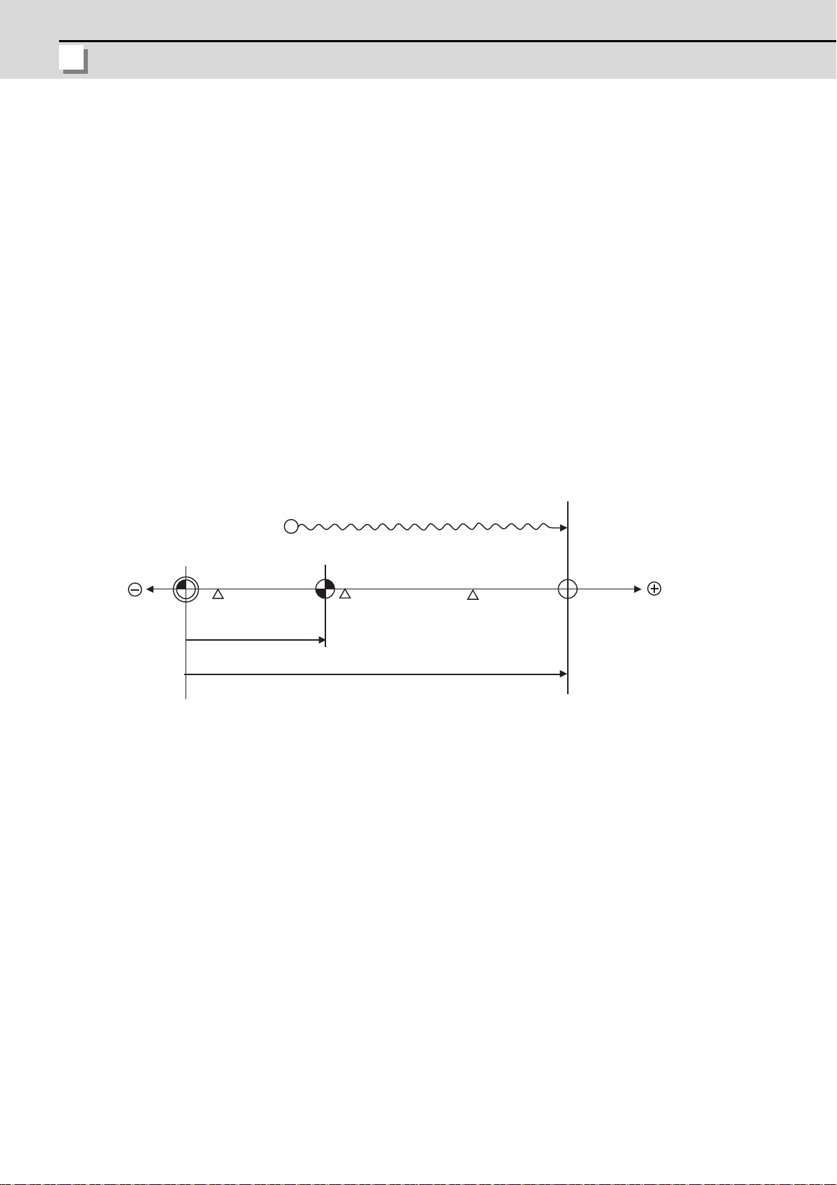
7 Setting the Position Detection System
MITSUBISHI CNC
7.1.2 Marked Point Alignment Method II
This is a method to align to the marked point (matchmark or marking line) on the machine.
(1) Select [Param] on the Mainte screen, then select [Abs pos param].
On the absolute position parameter screen, set "#2049 type (Absolute position detection method)" to "4" for the axis
for which the zero point is to be initialized.
(2) Turn the power OFF and ON.
(3) Select [Mainte] and then [To abs pos]. The absolute position setting screen appears.
(4) Select [Axis select]. Enter the axis name (in "#1022 axname2 (2nd axis name)") and press the INPUT key.
(5) Select the handle (handle axis) or JOG mode.
(6) Input "1" to "#0 Absolute posn set" on the absolute position setting screen.
(7) Input a value to "#2 Zero-P".
(8) Move the axis toward the machine basic position and align it to the marked point. ((a) in the following diagram)
Initialization start point
(a)
Basic machine
coordinate system
zero point
Reference position
parameter
"#2037 G53ofs"
Reference
position
"#2 Zero-P"
Mechanical basic position
(Marked point)
(9) Input "1" to "#1 Origin-P" on the absolute position setting screen.
(10) When the absolute position has been completed, "State" area on the absolute position setting screen shows
"Complete".
Select [Next axis] and execute the absolute position initialization for all the axes.
(11) Turn the power OFF and ON.
(Note 1) To change just the basic machine coordinate zero point, set "#0 Absolute posn set" and "#2 Zero-P", and then
turn the power OFF and ON.
(Note 2) If aligning to the marked point is attempted without passing the grid point even once after turning the power
ON, the operation message "Not Passed on grid" will appear. Return to a point before the last grid, and then
repeat from the step of aligning the axis on the marked point.
(Note 3) If the first grid point is covered by the grid mask ("#2028 grmask") as a result of return to the electric basic
position, the axis stops at the next grid point. Note that the zero point shift ("#2027 G28sft") is invalid.
(Note 4) This method is not interfered by the setting of "#2059 zerbas", and the basic position is always where the
marked point alignment is attempted.
78
Page 96

M700VS Series Setup Manual
7.1 Adjusting the Absolute Position Detection System
7.1.3 Other Setting Method
7.1.3.1 Machine End Stopper Method: Automatic Initialization
(1) Select [Param] -> [Abs.Posit.Param.] in the maintenance screen.
Set the following parameters in the "Abs.Posit.Param." screen.
Parameter Setting value
#2049 type (absolute position detection type)
#2054 clpush (current limit) 0 to 100
#2055 pushf (push speed) 1 to 999
#2056 aproch (approach point) 0 to 999.999
#2059 zerbas (zero point return parameter)
The parameters other than "#2049 type" can be set in the "Zero point set" screen.
(2) Turn the power OFF and ON.
(3) Select [Mainte] -> [To Abs pos.]. The absolute position setting screen will appear.
(4) Select [Axis select]. Enter the axis name (the name set in "#1022 axname2 (2nd axis name), and hold down INPUT
key.
1 (machine end stopper method
isselected)
1 (on the grid point immediately
beforethe stopper)
(5) Select [Auto init set] mode.
(6) Set "1" to "#0 Absolute posn set".
(7) Enter the value in "#2 Zero-P".
79
Page 97

7 Setting the Position Detection System
MITSUBISHI CNC
(8) Start JOG operation.
Machine end stopper
(mechanical basic
position)
Grid point
(electric basic
position)
"#2056 aproch"
Initialization start point
Push speed
a
b
c
d
e
Basic machine coordinate system
zero point
Reference
position
Reference position
parameter
"#2037 G53ofs"
"Machine end"
"#2 Zero-P" (#2059 zerbas=1)
"#2 Zero-P" (#2059 zerbas=0)
"#2 Zero-P" depends on the setting of "#2059 zerbas".
The axis moves automatically as follow.
1) The axis moves toward the machine end stopper at the push speed. (a in the diagram).
2) The axis pushes against the machine end stopper. After the current reached its limit continually during given
time period, the axis returns toward the approach point at the "push speed". (b in the diagram)
3) After arrived at the approach point, the axis moves toward the machine end stopper at the "push speed". (c in
the diagram)
4) The axis pushes against the machine end stopper. After the current reached its limit continually during the
given time period, the axis returns toward the grid point immediately before the stopper at the "push speed". (d
in the diagram)
If "#2059 zerbas" is set to "0" (absolute position origin point = mechanical basic position), the axis will stop
automatically at this point without moving in the opposite direction, and "Complete" appears in the [State] and
"0.000" in the [Machine end].
[State] will change as follow:
[Stopper1] -> [Zero-P. Rel.] -> [Stopper2] -> [Ret. Ref. P.]
(9) When the axis has reached the grid point immediately before the stopper (e in the diagram) and the absolute
position is established, "Complete" will appear in "State".
The distance between the machine end stopper and the grid point immediately before the stopper will appear in
[Machine end].
Select [Next axis] menu, and perform the absolute position initial set up for all axes.
(10) Turn the power OFF and ON.
80
Page 98

M700VS Series Setup Manual
7.1 Adjusting the Absolute Position Detection System
(Note 1) To change just the basic machine coordinate zero point, set "#0 Absolute posn set" and "#2 Zero-P", and then
Machine end stopper
(Mechanical basic
position)
Machine end
stopper
(Mechanical
basic position)
Looking from the basic machine coordinate system zero point,
the reference position is located far beyond the machine end
stopper, thus the reference position return cannot be carried out.
#2037 "G53ofs"
Basic machine coordinate
system zero point
Basic machine coordinate
system zero point
"#2 Zero-P"
Reference position
If the "#2 Zero-P" setting is "0", the
basic machine coordinate system
zero point is located on the machine
end stopper.
The direction of axis movement is
thus unpredictable.
turn the power OFF and ON.
(Note 2) If pressing against the machine end is attempted without passing the grip point once after turning the power
ON, the operation message "Not passed on grid" will appear. Return to a point before the last grid, and then
repeat from step of pressing against the machine end stopper.
(Note 3) If the first grid point is covered by the grid mask (#2028 grmask) as a result of return to the electric basic
position, the axis stops at the next grid point.
Note that zero-point shift amount (#2027 G28sft) is invalid.
(Note 4) Acceleration/deceleration during movement at the specified push speed is performed in smoothing-off
(stepfeed) mode.
(Note 5) If "0" is specified for "#2056 aproch" of the absolute position parameters, the machine zero point is regardedas
the approach point.
(Note 6) Automatic initialization is interrupted if one of the following events occurs. If it is interrupted, [State] indicates
"Jog Start" (after selecting the "Auto init set" mode if it is caused by mode change), so restart operation from
the step of JOG-start.
- An absolute position detection alarm occurs.
- Operation preparation signal turns OFF.
- The mode is changed.
- The system is reset.
If [State] is "Complete" before automatic initialization is started, "State" returns to "Complete" when power is
turned OFF and ON again without restarting the operation.
(Note7) Automatic initialization cannot be started in the following cases. The operation message "Can't start" will
appear if starting is attempted.
- When "#0 Absolute posn set" is not set.
- When the "#2 Zero-P" setting is inappropriate.
- When "#2055 pushf" is not set.
- When "Z71 Abs encoder failure 0005" has occurred.
In the above cases, if the "#2 Zero-P" setting is inappropriate, this means that the relation of "#2 Zero-P" and
"#2037 G53ofs" is inappropriate. That is, if "#2 Zero-P" is smaller than the "#2037 G53ofs", the machine end
stopper will be located between the basic machine coordinate system zero point and reference position; this
disables automatic initialization. (Refer to the following left figure.)
If "#2 Zero-P " is set to "0", the machine end stopper direction is unpredictable; this also disables automatic
initialization. (Refer to the following right figure.)
81
Page 99

7 Setting the Position Detection System
MITSUBISHI CNC
7.1.3.2 Machine End Stopper Method: Manual Initialization
Basic machine coordinate system
zero point
Reference
position
Zero return parameter
"#2037 G53ofs"
Grid point
(electric basic
position)
"Machine end"
Machine end stopper
(Mechanical basic
position)
"#2 Zero-P" (#2059 zerbas=1)
"#2 Zero-P" (#2059 zerbas=0)
"#2 Zero-P" depends on the setting of "#2059 zerbas".
(a)
(c)
(d)
(e)
(b)
Initialization start point
(1) Select [Param] -> [Abs.Posit.Param.] in the maintenance screen.
Set the following parameters in the "Abs.Posit.Param." screen.
Parameter Setting value
#2049 type (absolute position detection type)
#2054 clpush (current limit) 0 to 100
#2059 zerbas (zero point return parameter)
The parameters other than "#2049 type" can be set in the "Zero point set" screen.
(2) Turn the power OFF and ON.
(3) Select [Mainte] -> [To abs pos]. The absolute position setting screen will appear.
(4) Select [Axis select]. Enter the axis name (the name set in "#1022 axname2 (2nd axis name), and hold down INPUT
key.
(5) Select HANDLE (handle axis) or "JOG" mode.
(6) Set "1" to "#0 Absolute posn set".
(7) Enter an arbitrary value to "#2 Zero-P".
(8) Move the axis toward the machine end stopper. (a in the diagram)
(9) Press the axis against the machine end stopper. (b in the diagram)
The current limit is reached continually during the given time period. (c in the diagram)
The display for [State] changes from [Stopper] to [Release].
(10) Move the axis in the counter direction. (d in the diagram)
[Ret. Ref. P.] will appear in [State].
If "#2059 zerbas" is set to "0" (absolute position origin point = mechanical basic position), the axis will stop
automatically at this point without moving in the opposite direction, and "Complete" appears in the [State] and
"0.000" in the [Machine end].
(11) When the axis has reached the grid point immediately before the stopper (e in the diagram) and the absolute
position is established, "Complete" will appear in "State".
Select [Next axis] menu, and perform the absolute position initial set up for all axes.
(12) Turn the power OFF and ON.
1 (machine end stopper method is
selected)
1 (on the grid point immediately
before the stopper)
(Note 1) To change just the basic machine coordinate zero point, set "#0 Absolute posn set" and "#2 Zero-P", and then
(Note 2) If pressing against the machine end is attempted without passing the grip point once after turning the power
turn the power OFF and ON.
ON, the operation message "Not passed on grid" will appear. Return to a point before the last grid, and then
repeat from step of pressing against the machine end stopper.
(Note 3) If the first grid point is covered by the grid mask (#2028 grmask) as a result of return to the electric basic
position, the axis stops at the next grid point.
Note that zero-point shift amount (#2027 G28sft) is invalid.
82
Page 100

M700VS Series Setup Manual
7.1 Adjusting the Absolute Position Detection System
7.1.3.3 Dog-type
(1) Select [Param] -> [Abs.Posit.Param.] in the maintenance screen.
Set "3" for the axis for which the absolute position initialization is performed to "#2049 type (absolute position
detection type)".
(2) Turn the power OFF and ON.
(3) Select [Mainte] -> [To abs pos]. The absolute position setting screen will appear.
(4) Select [Axis select]. Enter the axis name (the name set in "#1022 axname2 (2nd axis name), and hold down INPUT
key.
(5) Execute the manual or automatic dog-type reference position return.
(6) When the reference position return is completed and the absolute position is establised, "Comp lete" will appear in
"State".
Select [Next axis] menu, and perform the absolute position initial set up for all axes.
(7) Turn the power OFF and ON.
(Note 1) If the dog-type reference position return is interrupted by resetting, the previous state ("Comp lete" or
"Illegality") will display in the [State] column.
(Note 2) With dog-type reference position return, reference position return can be executed again even if the [State] is
"Complete".
83
 Loading...