

Mitsubishi M68749 Datasheet

MITSUBISHI RF POWER MODULE
Nov. ´97
12345
6
ηT
ρin
(Pin:controlled)
ZG=50Ω, Load VSWR=4:1 (All phase)
°C
°C
H3
12345
6
56423
1
M68749
380-400MHz, 12.5V, 5W, DIGITAL MOBILE RADIO
OUTLINE DRAWING
3±0.3
7.25±0.8
12±1
16.5±1
33.0±1
43.5±1
66±0.5
60±0.5
51.5±0.5
φ 0.45±0.15
55.5±1
2-R2±0.5
Dimensions in mm
BLOCK DIAGRAM
PIN:
Pin : RF INPUT
VBB : BASE BIAS SUPPLY
VCC1: 1st. DC SUPPLY
VCC2: 2nd. DC SUPPLY
PO : RF OUTPUT
GND: FIN
ABSOLUTE MAXIMUM RATINGS (Tc=25°C unless otherwise noted)
Symbol Parameter Conditions Ratings Unit
VCC Supply voltage
VBB 9
Bias voltage
ZG=ZL=50Ω, VBB=8.5V
ZG=ZL=50Ω, VCC≤13.2V
17
ZG=ZL=50Ω
ZG=ZL=50Ω, VCC≤13.2V
ZG=ZL=50Ω
ZG=ZL=50Ω
-30 to +110TC (OP) Operation case temperature
-40 to +110Tstg Storage temperature
Note. Above parameters are guaranteed independently.
ELECTRICAL CHARACTERISTICS (Tc=25°C unless otherwise noted)
Symbol Parameter Test conditions
f
PO
Frequency range
Output power
Pin=200mW,VCC=12.5V,VBB=9V, ZG=ZL=50Ω
Total efficiency
2fO
3fO 3rd. harmonic
2nd. harmonic
VCC=12.5V, VBB=9V,
PO=5W (Pin:controlled), ZG=ZL=50Ω
Input VSWR
Gp Power gain
IMD3
3rd. internal modulation
5th. internal modulationIMD5
Load VSWR tolerance-
-
Stability
Note. Above parameters, ratings, limits and test conditions are subject to change.
Note 1. Stability is tested by sampling test (10pcs/Lot)
VCC=12.5V, VBB=9V, PO (AVE)=5W
(Pin:controlled) 2tone, ∆f=10kHz, ZG=ZL=50Ω
VCC=15.2V, VBB=9V, PO=13W
Pin=0-300mW, VCC=10-16V, VBB=9V,
PO ≤ 20W, ρI ≤ 3.0 (All phase), ZG=50Ω
No degradation or
destroy
No parastic oscillation Note 1
Limits
Min Max
380 400
13
15
-25
-30 dBc
28 dB
-25
-32
V
V
A6ICC Total current
mW300Pin (max) Input power
W25PO (max) Output power
Unit
MHz
W
%
dBc
-2.8
dBc
dBc
-
Nov. ´97
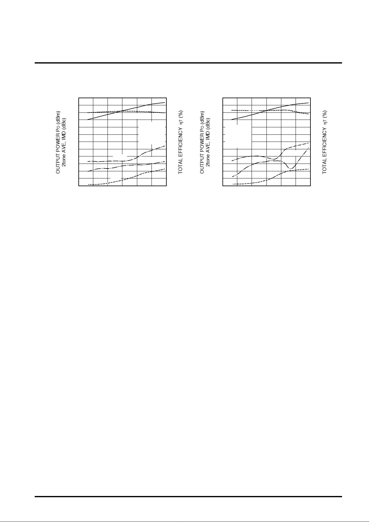
TYPICAL PERFORMANCE DATA
OUTPUT POWER, TOTAL EFFICIENCY,
50
40
30
20
10
0
-10
-20
-30
-40
-50
-60
-70
-15 -5 0 5 15
IMD VS. INPUT POWER
IMD3
ηT
-10 10
INPUT POWER Pin (dBm) 2tone AVE
GP
Tc=25°C
f=380MHz
VCC=12.5V
VBB=8.5V
IMD5
PO
100
80
60
40
20
0
MITSUBISHI RF POWER MODULE
M68749
380-400MHz, 12.5V, 5W, DIGITAL MOBILE RADIO
OUTPUT POWER, TOTAL EFFICIENCY,
50
40
30
20
10
0
-10
-20
-30
-40
-50
-60
-70
-15 -5 0 5 15
IMD VS. INPUT POWER
PO
Tc=25°C
f=400MHz
VCC=12.5V
VBB=8.5V
IMD3
IMD5
ηT
-10 10
INPUT POWER Pin (dBm) 2tone AVE
100
80
60
40
20
0
 Loading...